E TECH IM401 Private Land Mobile Radio for Vehicle (UHF) User Manual IM401
E-TECH Co., Ltd. Private Land Mobile Radio for Vehicle (UHF) IM401
UserManual.wiki
>
E TECH
>
IM401 User Manual
>
Users Manual II
Contents
1.
Users Manual I
2.
Users Manual II
Users Manual II
Navigation menu
Upload a User Manual
Namespaces
Wiki Guide
HTML
PDF
Info
Views
User Manual
Discussion / Help
Navigation
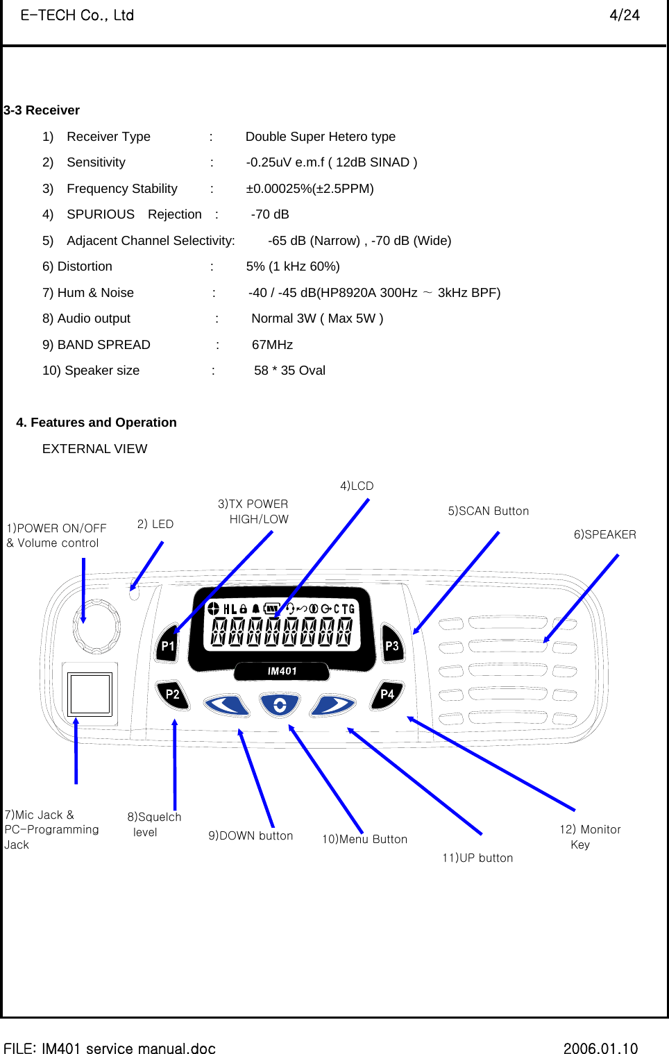
![8 FILE: IM401 service manual.doc 2006.01.10 E-TECH Co., Ltd 3/24 3. Technical Specifications 3-1 General 1) Frequency range : 403~470 MHz 2) Channels : 255 Channels 3) Channel spacing : 12.5 kHz/25 kHz 4) Communication method : Simplex 5) Antenna Impedance : 50 ohm 6) Power supply voltage : DC 13.6V 7) Current Drain : When Transmitting(40W) - < 9A When Receiving(3W) - < 1A Transmit standby - < 150mA 8) Microphone : External Condenser Mic 9) Operating temperature range: -30 +60℃∼ ℃ 10) Size : 178(W)x49(H)x195(D) 11) Weight : 1600g 3-2 Transmitter 1) Power Output : HIGH – 40W, LOW - 5W 2) Modulation : 8K50F3E/16K0F3E 3) Oscillator method : PLL 4) Frequency Stability : less than ±0.00025% (±2.5PPM) 5) Maximum frequency deviation: ±2.5 kHz(Narrow)/ ±5 kHz(Wide) 6) Audio Distortion : less than 5% (1 kHz 60%) 7) SPURIOUS Emission : -75 [dBc] 8) FM Hum & Noise : -40 / -45 [dB] (HP8920A 300Hz 3kHz BP∼F) 9) BAND SPREAD : 67[MHz]](https://usermanual.wiki/E-TECH/IM401.Users-Manual-II/User-Guide-757747-Page-3.png)

![8 FILE: IM401 service manual.doc 2006.01.10 E-TECH Co., Ltd 23/24 5. Antenna Installation 5-1 Antenna Installation and Compliance with Radio Frequency(RF) Energy Safety Standards [IMPORTANT NOTE] To assure optimum performance and compliance with RF Energy Safety standards, this antenna installation guidelines and Instructions are limited to metal-body vehicles with appropriate ground planes and take into account the potential exposure of backseat passengers and bystanders outside the vehicle. [NOTE] For mobile radios with rated power of 7 watts or less, the only installation restrictions are to use only E-tech approved antennas and install the antenna externally on metal body vehicles. For mobile radios with rated power greater than 7 watts, always adhere to all the guidelines and restrictions in 5.2 below. 5-2 Selecting an Antenna Site/Location on a Metal Body Vehicle 1. External installation – Check the requirements of the antenna supplier and install the vehicle antenna external to a metal body vehicle in accordance with those requirements. 2. Roof top – For optimum performance and compliance with RF Energy Safety standards, mount the antenna in the center area of the roof. 3. Trunk lid – On some vehicles with clearly defined, flat trunk lids, the antenna of some radio models (see restrictions below) can also be mounted on the center area of the trunk lid. For vehicles without clearly defined, flat trunk lids (such as hatchback autos, sport utility vehicles, and pick-up trucks), mount the antenna in the center area of the roof. Before installing an antenna on the trunk lid. • Be sure that the distance from the antenna location on the trunk lid will be at least 60cm (24 inches) from the front surface of the rear seat-back to assure compliance with RF Energy Safety standards. • Ensure that the trunk lid is grounded by connecting grounding straps between the trunk lid and the vehicle chassis. If these conditions can not be satisfied, then mount the antenna on the roof top ! 4. Mounting restrictions for certain radio models](https://usermanual.wiki/E-TECH/IM401.Users-Manual-II/User-Guide-757747-Page-23.png)
![8 FILE: IM401 service manual.doc 2006.01.10 E-TECH Co., Ltd 24/24 For more than 40 Watt VHF models, the 1/4 wave antenna should be mounted only in the center area of the roof, not on the trunk lid, to assure compliance with RF Energy Safety standards. 5. Ensure that the antenna cable can be easily routed to the radio. Route the antenna cable as far away as possible from any vehicle electronic control units and associated wiring. 6. Check the antenna location for any electrical interference. 7. Make sure any other mobile radio antenna on this vehicle is at least 30.48 cm (1 foot) away from this antenna. [NOTE] Any two metal pieces rubbing against each other (such as seat springs, shift levers, trunk and hood lids, exhaust pipes, etc.) in close proximity to the antenna can cause severe receiver interference. 5-3 Antenna Installation Procedure 1. Mount the antenna according to the instructions provided with the antenna kit. Run the coaxial cable to the radio mounting location. If necessary, cut off the excess cable and install the cable connector. 2. Connect the antenna cable connector to the radio antenna connector on the rear of the radio. 5-4 Completing the Installation 1. Mount the microphone clip to a convenient spot near your radio. 2. Your microphone has a telephone-type connector at the end of is cord. Plug the microphone into the control head connector. 3. To complete your radio installation, plug the power cable into the radio power connector.](https://usermanual.wiki/E-TECH/IM401.Users-Manual-II/User-Guide-757747-Page-24.png)