E TECH IP400 FM Handheld Transceiver User Manual 1
E-TECH Co., Ltd. FM Handheld Transceiver Users Manual 1
UserManual.wiki
>
E TECH
>
IP400 User Manual
>
Users Manual 1
Contents
1.
Users Manual 1
2.
Users Manual 2
Users Manual 1
Navigation menu
Upload a User Manual
Namespaces
Wiki Guide
HTML
PDF
Info
Views
User Manual
Discussion / Help
Navigation
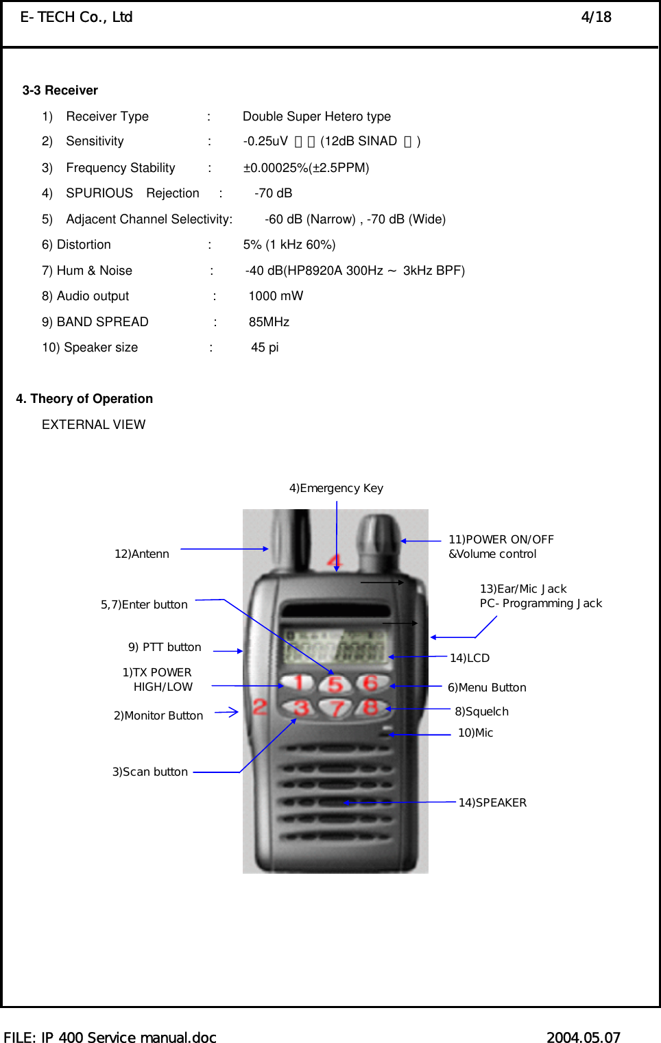
![FILE: IP 400 Service manual.doc 2004.05.07 E-TECH Co., Ltd 3/18 3. Technical Specifications 3-1 General 1) Frequency range : 405~490 MHz 2) Channels : 255 Channels 3) Channel spacing : 12.5 kHz/25 kHz 4) Communication method : Simplex 5) Antenna Impedance : 50 ohm 6) Antenna : Whip Antenna 7) Power supply voltage : LI-1700mAh Li-Ion battery pack(Voltage: 7.5V DC) 8) Current Drain : When Transmitting(4W) - < 2A When Receiving(0.5W) - < 300mA Transmit standby - < 60mA Receiver standby(PSC MODE) - < 50mA 9) Microphone : Internal Condenser Microphone(External Speaker Micro phone is available) 10) Operating temperature range: -30 +℃~ 60℃ 11) Size : 56(W)x100(H)x34(D) 12) Weight : 285g 3-2 Transmitter 1) Power Output : HIGH – 4W, LOW - 1W 2) Modulation : 8K5F3E/16K0F3E 3) Oscillator method : PLL 4) Frequency Stability : less than ±0.00025% (±2.5PPM) 5) Maximum frequency deviation: ±2.5 kHz(Narrow)/ ±5 kHz(Wide) 6) Audio Distortion : less than 5% (1 kHz 60%) 7) SPURIOUS Emission : -36 [dBm] 8) FM Hum & Noise : -40 [dB] (HP8920A 300Hz 3kHz BP~F) 9) BAND SPREAD : 85 [MHz]](https://usermanual.wiki/E-TECH/IP400.Users-Manual-1/User-Guide-447951-Page-5.png)
![FILE: IP 400 Service manual.doc 2004.05.07 E-TECH Co., Ltd 18/18 6-2 Voltage Check 1) Set up the radio frequency to (405.025[Mhz]) then measure whether R/Tx voltage is over 0.8[v]. 2) Set up the radio frequency (489.975[Mhz]) then measure whether R/Tx voltage is under 5[v]. 3) When Un-Lock is display on LCD means defective goods. 6-3 Transmitter 1) At the frequency range of (446.025[MHz]), set up Tx mode then adjust frequency by using VR 301 at the level of ±150[Hz]. High power should be 3~4.6[W]. In case of out of this range, you can check whether current is under 2A then adjust at the level of 3.8W by using VR501. Low power should be 1[W] ±0.2[W]. In case of out of range, you can adjust it by using VR502. FM DEVIATION should be adjusted at the level of 2.1[khz] ±0.1[khz] by using VR303. Low frequency input is 1[kHz],50[mV]. 2) After you set up MOD at the frequency range of (446.025[MHz]), adjust TONE DEVIATION by using VR 302 at the level of 0.45[kHz] ±0. k05[zH] . 6-4 Receiver, Set up Receiving Mode at (SSG -60d[Bm]). At the frequency range of 446.025[MHz], FM 1.5[kHz], adjust Volume at (0.5[W]). Sensitivity at the level of 12[dB] SINAD, check whether it is under -119[dBm]., and SQ(LEVEL8) is between -117[dBm] ~ -123[dBm by using VR101. In case of out of range, adjust it at 120[dBm]. 6-5 Wideband specification check At the frequency range of (446.025[MHz]), you have to check whether FM DEVIATION should be (3.6 ~ 4.8[kHz]), in case of 1G-4(446.025[MHz]), TONE DEVIATION should be (0.5~1.2[KHz]). Also, you have to check whether in case of 1G-2(446.025[MHz]), sensitivity should be (12[dB] SINAD, -119[dBm]). SQ sensitivity is between -116[dBm] and -124[dBm] 6-6 FINAL(QC) Inspect specification 1) 456.025[MHz] Narrow a. Frequency : ±300[Hz] b. Output power(L/H) : 0.7 ~ 1.2[W] / 3 ~ 4.6[W] c. FM DEVIATION(Narrow) : 1.8 ~ 2.5[kHz](1[kHz], 50[mV]) d. TONE DEVIATION : 0.3 ~ 0.6[kHz] e. Sensitivity : < -117[dBm] f. SQ Sensitivity : -116[dBm] ~ -124[dBm]( 2) 456.025[MHz] Wide band a. FM DEVIATION(Wide band) : 3.8 ~ 5.0[kHz](1[kHz], 50[mV]) b. TONE DEVIATION : 0.5 ~ 1.2[kHz] c. Sensitivity : < -117[dBm] d. SQ Sensitivity : -116[dBm] ~ -124[dBm]](https://usermanual.wiki/E-TECH/IP400.Users-Manual-1/User-Guide-447951-Page-20.png)