E TECH IS400 FM Handheld Transceiver User Manual
E-TECH Co., Ltd. FM Handheld Transceiver Users Manual
E TECH >
Users Manual

FILE: IS 400 service manual.doc 2004.05.07
E-TECH Co., Ltd 1/16
▶Table of Contents◀
1. Introduction
2. Description of Unit
3. Technical Specifications
4. Theory of Operation
5. Circuit Descriptions
6. Parts List
7. Block Diagram
8. CONTROL Layout (Upper Side)
9. CONTROL Layout (Bottom Side)
10. RF Layout (Upper Side)
11. RF Layout (Bottom Side)
12. Circuit Diagram

FILE: IS 400 Service manual.doc 2005.11.29
E-TECH Co., Ltd 2/16
1. Introduction
IS400 has a compact size with a various features in the range of 405~490MHz. IS400
Has a various features shown as below.
IS400 constructed with a microprocessor controlled, temperature compensated Phase Locked
Loop(PLL) frequency synthesizer. The radio features a double conversion receiver and a direct FM
transmitter modulator. A special integrated circuit provides support to sub-audible signaling(CTCSS & DCS)
and most of the receiving parts are switched off periodically in the power save mode to reduce battery current
drain during standby.
2. Description of Unit
Items Model
Radio IS400
Antenna IA-444
1700mAh Li-Ion battery pack BL 1700
Desktop rapid charter IC-170
Adaptor
Supplied
Package
User manual
Items Model
External / Speaker Microphone ES-1
Earpiece Microphone EP-1
Earpiece VOX Microphone EV-1
Accessories
VOX & PTT Headset VP-1

FILE: IS 400 Service manual.doc 2005.11.29
E-TECH Co., Ltd 3/16
3. Technical Specifications
3-1 General
1) Frequency range : 405~490 MHz
2) Channels : 255 Channels
3) Channel spacing : 12.5 kHz/25 kHz
4) Communication method : Simplex
5) Antenna Impedance : 50 ohm
6) Antenna : Helical Antenna
7) Power supply voltage : LI-1700mAh Li-Ion battery pack(Voltage: 7.4V DC)
8) Current Drain : When Transmitting(4W) - < 2A
When Receiving(0.5W) - < 300mA
Transmit standby - < 60mA
Receiver standby(PSC MODE) - < 50mA
9) Microphone : Internal Condenser Microphone(External Speaker Micro
phone is available)
10) Operating temperature range: -30 +℃~ 60℃
11) Size : 56(W)x100(H)x34(D)
12) Weight : 285g
3-2 Transmitter
1) Power Output : HIGH –4W, LOW - 1W
2) Modulation : 8K5OF3E/16KOF3E
3) Oscillator method : PLL
4) Frequency Stability : less than ±0.00025% (±2.5PPM)
5) Maximum frequency deviation: ±2.5 kHz(Narrow)/ ±5 kHz(Wide)
6) Audio Distortion : less than 5% (1 kHz 60%)
7) SPURIOUS Emission : -36 [dBm]
8) FM Hum & Noise : -40 [dB] (HP8920A 300Hz 3kHz BP~F)
9) BAND SPREAD : 85 [MHz]
FILE: IS 400 Service manual.doc 2005.11.29
E-TECH Co., Ltd 4/16
3-3 Receiver
1) Receiver Type : Double Super Hetero type
2) Sensitivity : -0.25uV 이하(12dB SINAD 시)
3) Frequency Stability : ±0.00025%(±2.5PPM)
4) SPURIOUS Rejection : -70 dB
5) Adjacent Channel Selectivity: -60 dB (Narrow) , -70 dB (Wide)
6) Distortion : 5% (1 kHz 60%)
7) Hum & Noise : -40 dB(HP8920A 300Hz 3kHz ~BPF)
8) Audio output : 1000 mW
9) BAND SPREAD : 85MHz
10) Speaker size : 45 pi
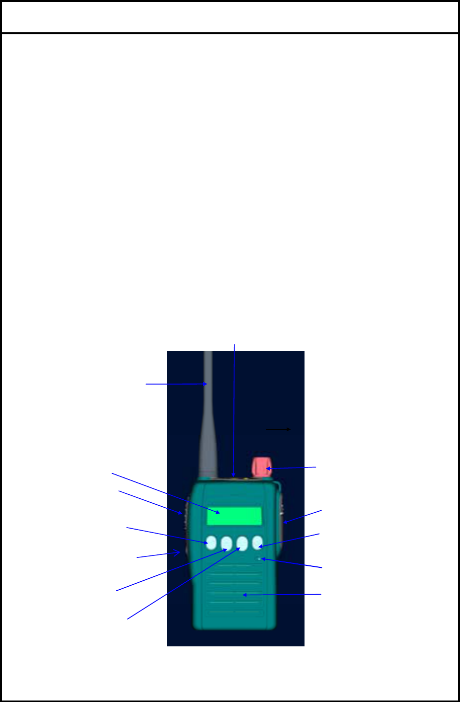
4. Theory of Operation
EXTERNAL VIEW
1)Antenna
13)Emergency key
11)Mic
2)LCD
5)Monitor Button
10) Menu Button
8)Power ON/OFF
& Volume control
9)Ear/Mic JACK
12)SPEAKER
6) UP button
7)DOWN Button
4) TX POWER
HIGH/LOW
3) PTT Button

FILE: IS 400 Service manual.doc 2005.11.29
E-TECH Co., Ltd 5/16
4-1 Features & Operation
1. Monitor
Press the Monitor key momentarily to disable the Tone squelch.
2. Radio Call
By using Various 5Tone, individual / Group call is available.
16 Receiving codes are available as well as open call.
3. Missed calls list
16 Missed calls can be listed. If a call remains unanswered, the call will be stored
by the radio.
4. contact list
During a call, the contact list may be used to give access to up to 16 preprogrammed
numbers accessed via the menu.
5. status list
A status is a code for transmitting prearranged messages, e.g. status “05” may indicate
“launch”. Status list contains up to 30 entries.
6. Channel : 255 channel
7. Scan ON/off
8. Power level : Power level is adjustable in each channel respectively.
9. Talkaround on/off
10. Emergency :
11. Lone Worker
12. Tx Tone select : In the menu, tx dcs /ctcss tone is adjustable.
13. Rx Tone select : In the menu, rx dcs /ctcss tone is adjustable.
14. Group : Defines group tone. You can select tone code for group, and it is used as a default value
. 0~9 and a, b, c, d available. And “A” is used as a basic value..
15. BEEP ON/OFF : BEEP sound ON/OFF.
16. KEY LOCK : LOCK/UNLOCK Button KEY.
17. SQUELCH : Squelch level is adjustable
18. AUTO SQUELCH : Squelch level is adjustable automatically by surroundings.
19. DTMF ON/OFF : DTMF function is available.
20. VOX : VOX LEVEL is adjustable by pushing up and down button.
21. AUTO VOX : VOX level is adjustable automatically by surroundings.
22. P - SCAN : Priority Scan
23. POWER SAVE : Power save mode is available.
24. PASS WORD : This function is useful for security reason.
25. LOCATION INDICATE : Indicate where the radio is located by blinking green light every 7 seconds.
26. SCRMABLE : Internal Voice Scrambler is available.
27. STUN / UNSTUN : For added security and to avoid abuse of the radio system in which you operate
a feature known as Stun/Unstun is included in your radio.
28. BACKLIGHT : Lamp is lighting when you check LCD status.
FILE: IS 400 Service manual.doc 2005.11.29
E-TECH Co., Ltd 6/16
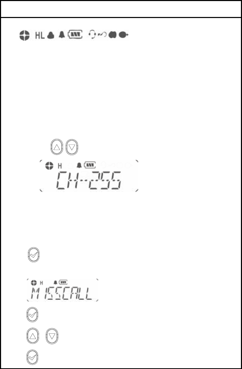
4-2 LCD Display and Icons
1.ANT GAZE ; Shows the received signal strength.
2.TX POWER HIGH: Indicate power level
3.KEY LOCK: Appears during key lock function is ON.
4.ALART(BEEP) ON/OFF: Appears when beep sound is turned ON.
5.Battery level indicator: Indicates reaming battery power.
6.VOX ON/OFF: Appears when VOX function is turned On.
7.SCAN: Appears when Scan function is activated.
8.SCRAMBLE: Appears while the voice scrambler function is activated.
9.TALK AROUND Indicator.
4-3 Features
1. Channel
This radio offers up to 255 channels
1). By using button, you can select the desired channel.
2. Missed calls list
Up to 16 calls can be stored. If the same radio calls more than once, only the most recent call is stored.
When fifteen calls have been stored by the radio, depending on the radio programming the sixteenth call
received may overwrite the first or not be stored by the radio.
1). to enter Menu Mode.
2) Display shows
3) to select
4) or to scroll list
5) to exit
FILE: IS 400 Service manual.doc 2005.11.29
E-TECH Co., Ltd 7/16
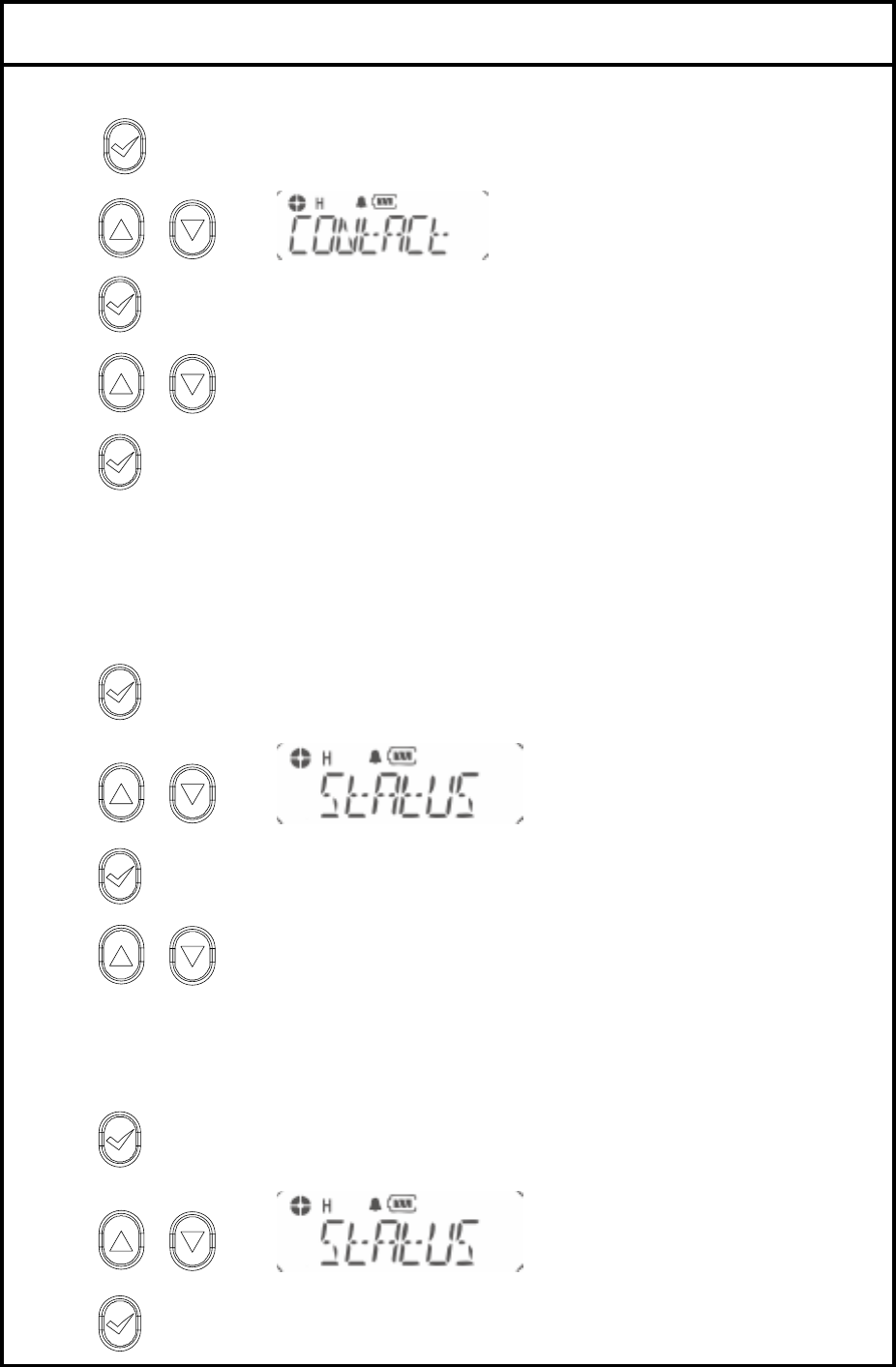
3. Contact list
1). to enter Menu Mode.
2) or to until
3) to select
4) or to scroll list
5) to exit
4. Status call list
4-1. Making STATUS call
1) to enter Menu Mode.
2) or to until
3) to select
4) or to scroll list
5) Push PTT KEY for sending message on the LCD.
4-2 Make STATUS Message
1) to enter Menu Mode.
2) or to until
3) to select
FILE: IS 400 Service manual.doc 2005.11.29
E-TECH Co., Ltd 8/16
4) or to scroll list
5) to SELECT
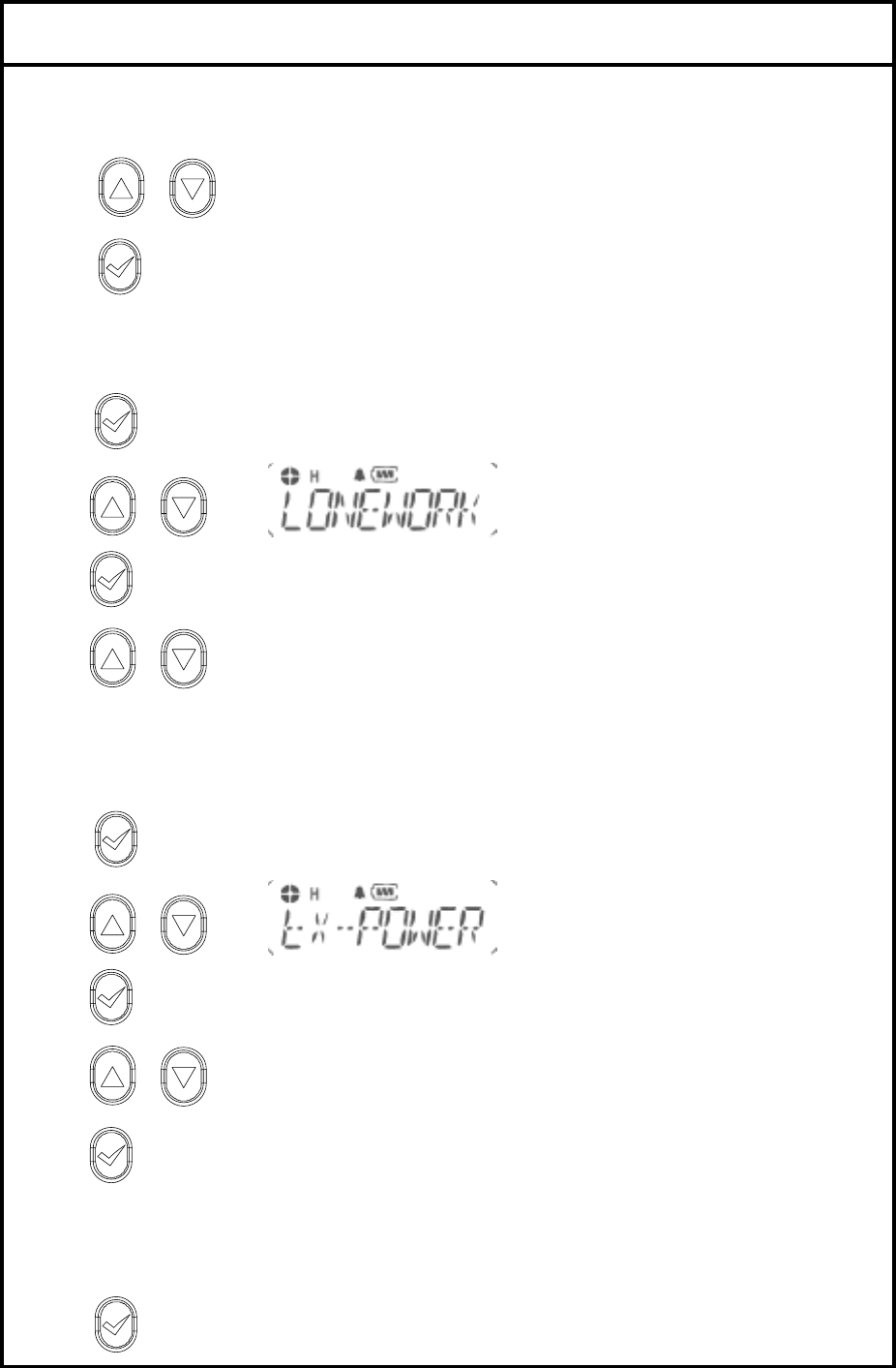
5. Lone work
1). to enter Menu Mode.
2) or to until
3) to select
4) or to select ON/OFF
6. Tx power
.
1). to enter Menu Mode.
2) or to until
3) to select
4) or to select HIGH / LOW POWER
5) to select
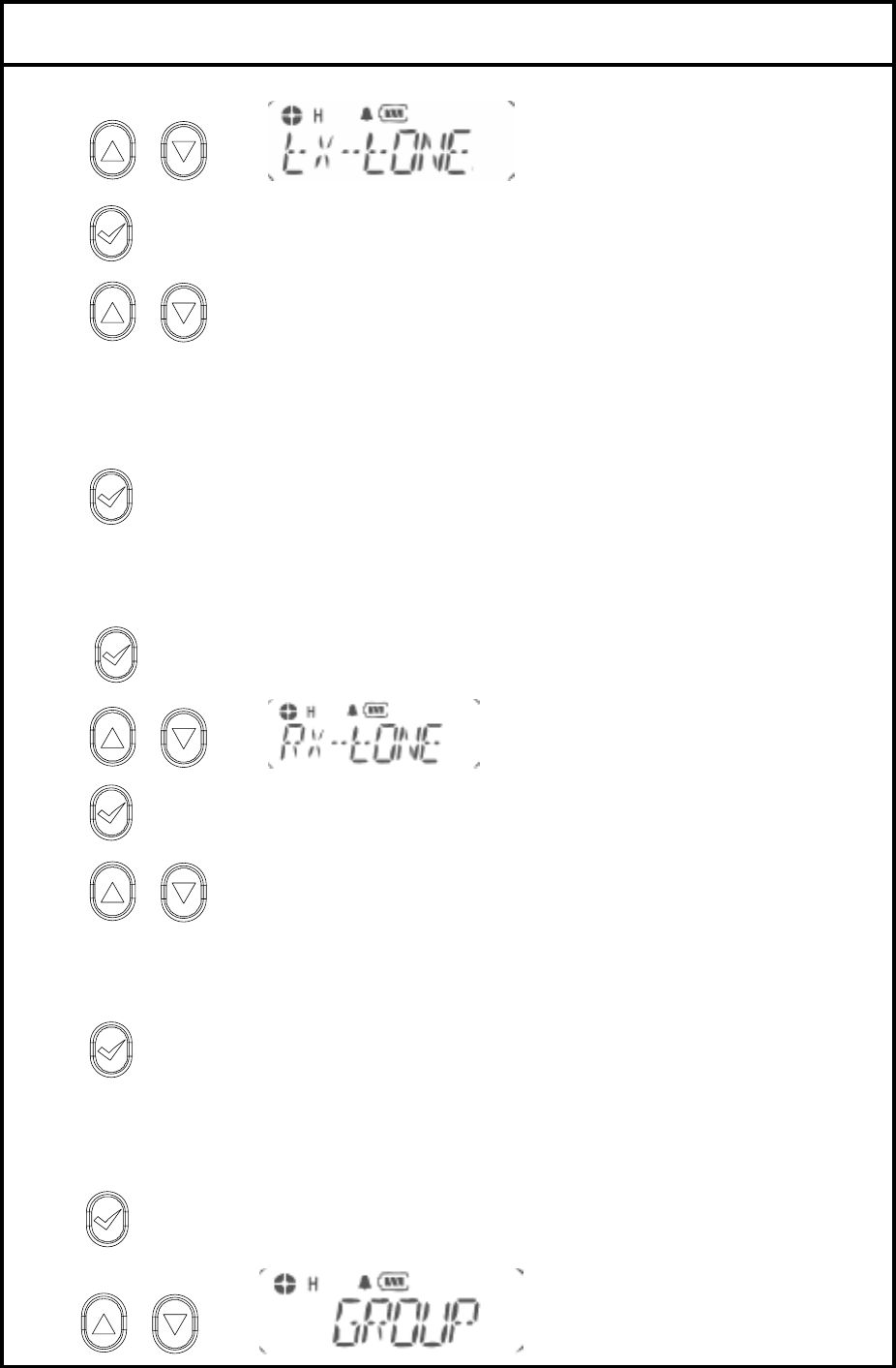
7. Tx Tone
Selecting Transmitting TONE(CTCSS/DCS).
1). to enter Menu Mode.
FILE: IS 400 Service manual.doc 2005.11.29
E-TECH Co., Ltd 9/16
2) or to until
3) to select
4) or to Select TONE을 either CTCSS or DCS.
0= NON TONE
1-38 CTCSS
101 – 183 DCS TONE
5) to select exit
8. Rx Tone
Changing Receiving TONE(CTCSS/DCS).
1). to enter Menu Mode.
2) or to until
3) to select
4) or to select TONE either CTCSS or DCS.
0= NON TONE
1-38 CTCSS
101 – 183 DCS TONE.
5) to select exit
9. Group
Changing GROUP Tone.
1). to enter Menu Mode.
2) or to until
FILE: IS 400 Service manual.doc 2005.11.29
E-TECH Co., Ltd 10/16
3) to select
4) or to select scroll list
5) to select exit
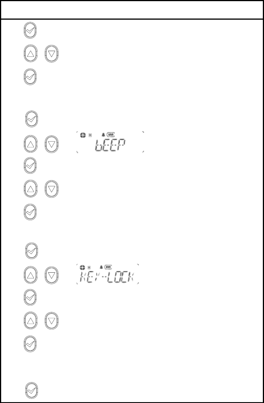
10. Beep on/off
1). to enter Menu Mode.
2) or to until
3) to select
4) or to select on off .
5) to select
11. Key lock
1). to enter Menu Mode.
2) or to until
3) to select
4) or to select key lock /unlock.
5) to select
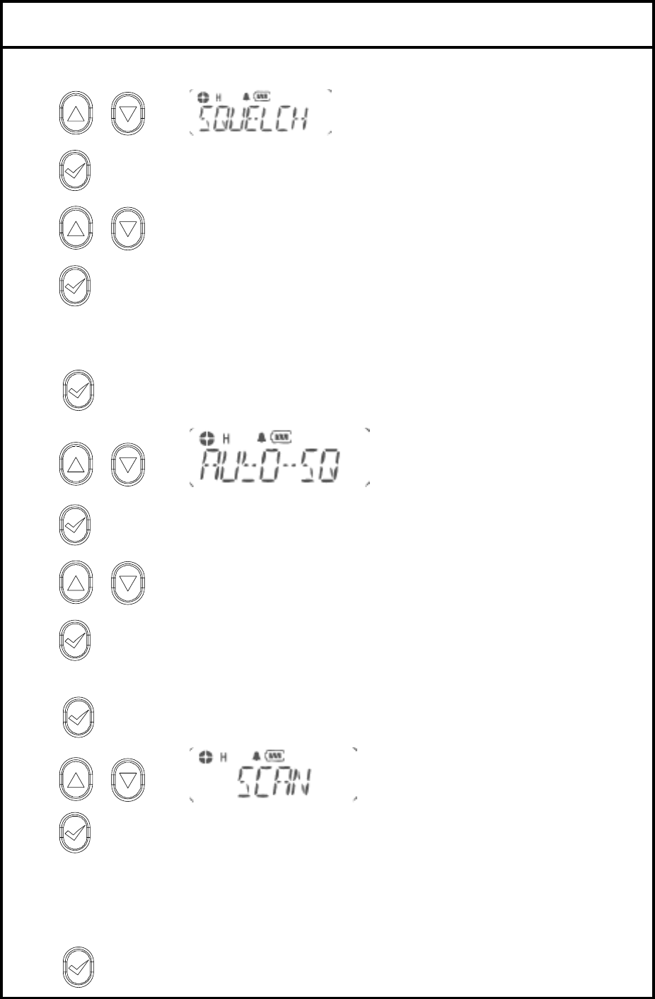
12. Squelch level
16 level is available. 0 = terminate sq function
1). to enter Menu Mode.
FILE: IS 400 Service manual.doc 2005.11.29
E-TECH Co., Ltd 11/16
2) or to until
3) to select
4) or to the scroll list
5) to select exit
13. Auto Squelch
1). to enter Menu Mode.
2) or to until
3) to select
4) or to select on /off .
5) to select
14. Scan
1). to enter Menu Mode.
2) or to until
3) to scan.
4) Push PTT for exit
15. DTMF
1). to enter Menu Mode.

FILE: IS 400 Service manual.doc 2005.11.29
E-TECH Co., Ltd 12/16
2) or to until
3) to select
4) or to select ON /OFF.
5) to select
16. Vox on/off
1). to enter Menu Mode.
2) or to until
3) to select
4) or to select ON /OFF.
5) to select
17. Vox Level
16 level is available..
1). to enter Menu Mode.
2) or to until
3) to select
4) or to scroll list
5) to select for exit
FILE: IS 400 Service manual.doc 2005.11.29
E-TECH Co., Ltd 13/16
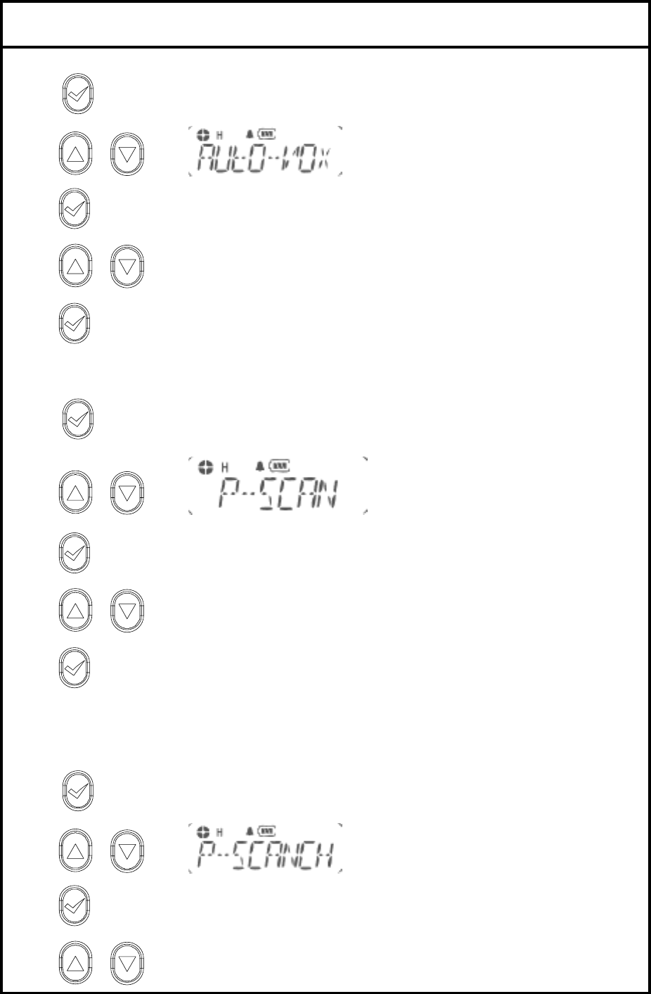
18. Auto Vox
1). to enter Menu Mode.
2) or to until
3) to select
4) or to select ON /OFF.
5) to select
19. Priority Scan
1). to enter Menu Mode.
2) or to until
3) to select
4) or to select ON /OFF.
5) to select
20. Priority scan CH
1). to enter Menu Mode.
2) or to until
3) to select
4) or to scroll list

FILE: IS 400 Service manual.doc 2005.11.29
E-TECH Co., Ltd 14/16
5) to select for exit
21. Power save
1). to enter Menu Mode.
2) or to until
3) to select
4) or to select ON /OFF.
5) to select
22. Talkaround
1). to enter Menu Mode.
2) or to until
3) to select
4) or to select ON /OFF.
5) to select
23. Password
1). to enter Menu Mode.
2) or to until
FILE: IS 400 Service manual.doc 2005.11.29
E-TECH Co., Ltd 15/16
3) to select
4) or to select ON /OFF.
5) to select
24. Password CH
1). to enter Menu Mode.
2) or to until
3) to select
4) ---- will display on the LCD( enter old password)
or by pushing up and down KEY to change password.
by pushing enter KEY to change digit of password.
5) Enter new password by 4 digit.
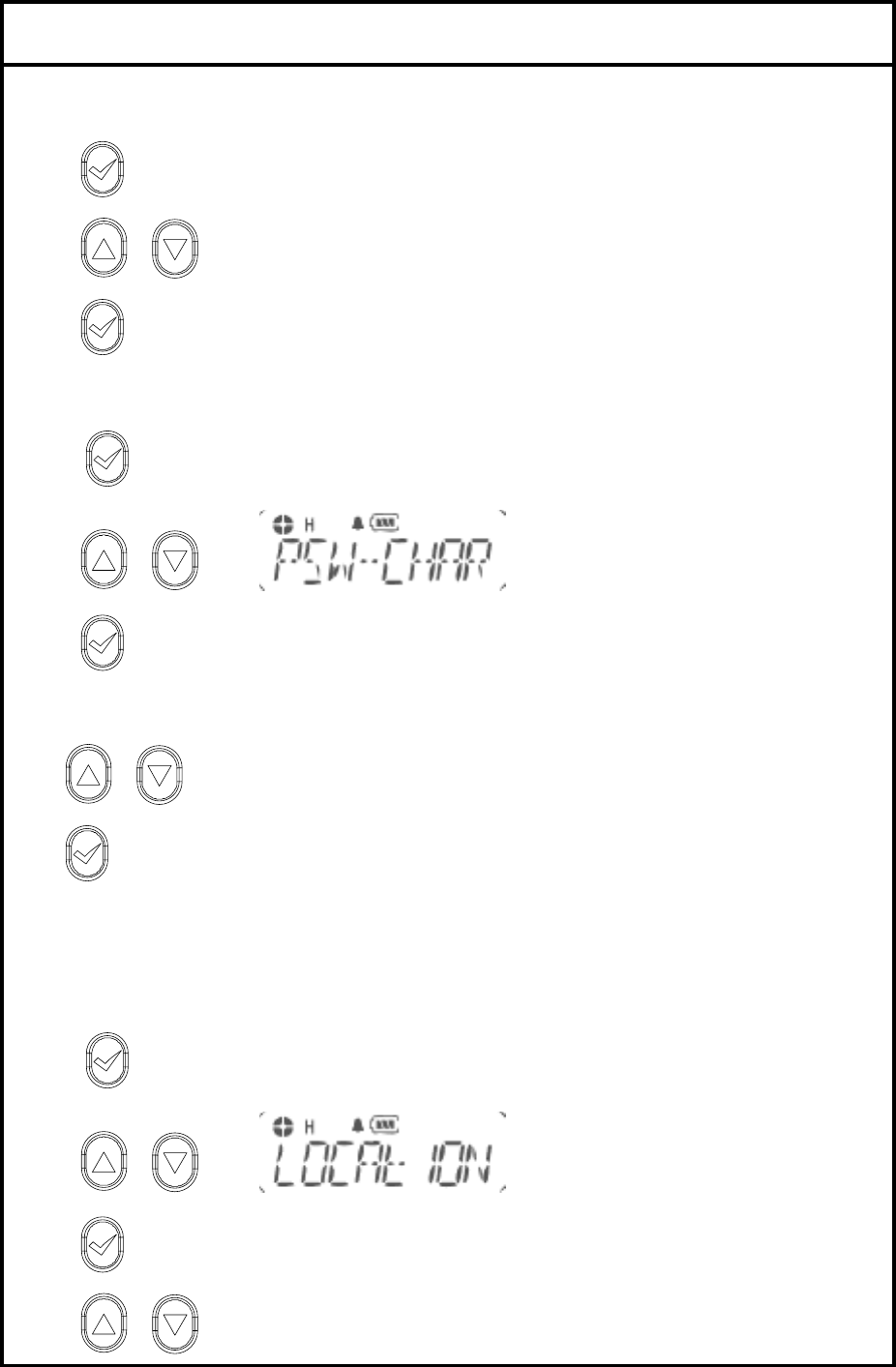
25. Location
Indicate where the radio is located by blinking green light every 7 seconds.
1). to enter Menu Mode.
2) or to until
3) to select
4) or to select ON /OFF.
FILE: IS 400 Service manual.doc 2005.11.29
E-TECH Co., Ltd 16/16
5) to select
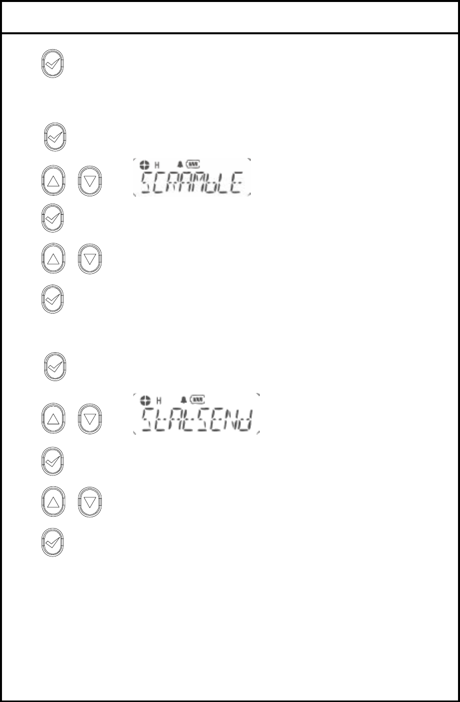
26. Scramble
1). to enter Menu Mode.
2) or to until
3) to select
4) or to select ON /OFF.
5) to select
27. Status call Send
1). to enter Menu Mode.
2) or to until
3) to select
4) or to select ON /OFF.
5) to select
5. Circuit Description.
5-1 Transmitter
1) MIC AMP Circuit
Voice signal from the microphone are applied to microphone amplifier U303. U303 contains a
low-pass filter that has a 6dB/oct response between 300Hz and 3kHz and eliminate above
3kHz. The pre-emphasized audio signal is applied to VR302 to adjust maximum frequency
deviation.

FILE: IS 400 Service manual.doc 2005.11.29
E-TECH Co., Ltd 17/16
2) VCO circuit
The transmit frequency is directly generated by the Colpitts oscillation circuit contains Q402,Q403.
3) POWER AMP
Signals from Q202, Q206 is supplied through antenna switch Q203,Q204 to a low-pass filter made up
and then applied to Antenna Jack.
5-2 Receiver
1) LOWPASS FILTER and Antenna switching circuit.
Signals from antenna connector fed to the antenna switching circuit through the low pass filter
consisting of L212~214. In receiving mode, D204, D202 is turned off, isolates the antenna from the
transmitter circuit and matching circuitry, so that the incoming signals are fed to the RF amplifier
through L211.
2) RF AMP Circuit
The signals from the switching circuit are fed to the RF amplifier Q101 through a band pass filter made
up of molded coil, vvc diode and capacitor.
3) MIXER Circuit
The amplified signals are fed to Gate 1 of the first mixer Q102. First local oscillator signal is supplied
to Gate 2 of Q102 from the PLL circuit to convert the RF signals into 21.4MHz first IF signal.
4) IF Circuit
The first signals from Q102 are fed to the matched pair crystal filter FL101, then IF signals are amplified
in Q103. And those signals are fed to U101 which is composed of the second local oscillator, second
local oscillator, second mixer, limiter amplifier, quadrature detector and active filter circuit. The second
local oscillator at 20.945MHz with X 101 and is fed to the second mixer with the first IF signals to
convert into 455kHz second IF signals.
5) Audio and squelch Circuit
The detected audio signals are put through a 6dB/oct de-emphasis circuit made up of Q602.
The signal is then applied to audio power amplifier U603 to obtain enough power to driver the speaker.
Part of the recovered noise signal is fed to the integrated operational amplifier inside U101 which
makes up an low pass filter. The sensitivity of squelch is adjusted by VR 101.
5-3 VCO Circuit
The transmit / receive frequency is directly generated by the Colpitts oscillation circuit contains Q402,
Q405.