E Z Go 602080 Users Manual
602080 to the manual cf091c0d-2747-4ace-bf5f-0b1511a819aa
2015-02-06
: E-Z-Go E-Z-Go-602080-Users-Manual-536968 e-z-go-602080-users-manual-536968 e-z-go pdf
Open the PDF directly: View PDF ![]() .
.
Page Count: 64
- ModelsNotesFS.pdf
- OWNER’S MANUAL AND SERVICE GUIDE
- This vehicle has been designed and manufactured in the United States of America (USA) as a ‘World Vehicle’. The Standards and Specifications listed in the following text originate in the USA unless otherwise indicated.
- The use of non Original Equipment Manufacturer (OEM) approved parts may void the warranty.
- Overfilling battery may void the warranty.
- Tampering with or adjusting the governor to permit vehicle to operate at above factory specifications will void the vehicle warranty.
- When servicing engines, all adjustments and replacement components must be per original vehicle specifications in order to maintain the United States of America Federal and State emission certification applicable at the time of manufacture.
- BATTERY PROLONGED STORAGE
- All batteries will self discharge over time. The rate of self discharge varies depending on the ambient temperature and the age and condition of the batteries.
- A fully charged battery will not freeze in winter temperatures unless the temperature falls below -75° F (-60° C).
- SafetyInfoFS.pdf
- J2258FS.pdf
- TextFSRevised.pdf
- WELCOME
- BEFORE INITIAL USE
- CAPABILITIES
- COMMON SENSE OPERATION
- RUN-IN
- CONTROLS & INDICATORS
- MAINTENANCE
- PERIODIC SERVICE SCHEDULE
- Fig. 21 Periodic Service Schedule
- BASIC SERVICE PARTS
- LIFTING THE VEHICLE
- OIL
- SPARK PLUGS
- ALTERNATOR BELT
- AIR CLEANER
- FUEL FILTER
- LUBRICATION POINTS
- BATTERY
- JUMP STARTING
- VEHICLE CLEANING AND CARE
- LABELS AND PICTOGRAMS
- WHEELS AND TIRES
- LIGHT BULB REPLACEMENT
- FUSE REPLACEMENT
- SPARK ARRESTER
- PROLONGED STORAGE
- FRONT AND REAR AXLES
- TRANSFER CASE
- AIR INTAKE AND COOLING FINS
- BRAKES
- CAPACITIES
- HARDWARE
- GenSpecsFS.pdf
- AppendixAFS.pdf
- AppendixAFS.pdf
- ModelsNotesFS.pdf
- OWNER’S MANUAL AND SERVICE GUIDE
- This vehicle has been designed and manufactured in the United States of America (USA) as a ‘World Vehicle’. The Standards and Specifications listed in the following text originate in the USA unless otherwise indicated.
- The use of non Original Equipment Manufacturer (OEM) approved parts may void the warranty.
- Overfilling battery may void the warranty.
- Tampering with or adjusting the governor to permit vehicle to operate at above factory specifications will void the vehicle warranty.
- When servicing engines, all adjustments and replacement components must be per original vehicle specifications in order to maintain the United States of America Federal and State emission certification applicable at the time of manufacture.
- BATTERY PROLONGED STORAGE
- All batteries will self discharge over time. The rate of self discharge varies depending on the ambient temperature and the age and condition of the batteries.
- A fully charged battery will not freeze in winter temperatures unless the temperature falls below -75° F (-60° C).

TM
602080
REVISED DATE: JAN. 2007

SAFETY
(NOTES, CAUTIONS AND WARNINGS CONTINUED ON INSIDE OF BACK COVER)
NOTES, CAUTIONS AND WARNINGS
Throughout this guide NOTE, CAUTION and WARNING
will be used.
A NOTE indicates a condition that should be
observed.
A CAUTION indicates a condition that
may result in damage to the vehicle.
A WARNING indicates a
hazardous condition that
could result in severe
injury or death.
Observe these NOTES, CAUTIONS and WARNINGS;
be aware that servicing a vehicle requires mechanical
skill and a regard for conditions that could be hazardous.
Improper service or repair may damage the vehicle or
render it unsafe.
Engine exhaust from this
product contains chemi-
cals known, in certain
quantities, to cause cancer, birth defects, or other
reproductive harm.
The exhaust emissions of this vehicles’ engine
complies with regulations set forth by the Envi-
ronmental Protection Agency (EPA) of the United States of
America (USA) at time of manufacture. Significant fines could
result from modifications or tampering with the engine, fuel,
ignition or air intake systems.
Battery posts, terminals
and related accessories
contain lead and lead
compounds. Wash hands after handling.
This spark ignition system meets all require-
ments of the Canadian Interference-Causing
Equipment Regulations.
Read and understand the following warnings
before attempting to operate the vehicle:
To prevent personal
injury or death, observe
the following:
When vehicle is to be left unattended, engage parking
brake, move direction selector to ‘F’ (forward)
position, turn key to ‘OFF’ position and remove key.
Drive vehicle only as fast as terrain and safety
considerations allow. Consider the terrain and traffic
conditions. Consider environmental factors which
effect the terrain and the ability to control the vehicle.
Avoid driving fast down hill. Sudden stops or change
of direction may result in a loss of control. Use service
brake to control speed when traveling down an incline.
Use extra care and reduced speed when driving on
poor surfaces, such as loose dirt, wet grass, gravel,
etc.
All travel should be directly up or down hills.
Use extra care when driving the vehicle across an
incline.
Stay in designated areas and avoid steep slopes. Use
the parking brake whenever the vehicle is parked.
Keep feet, legs, hands and arms inside vehicle at all
times.
Avoid extremely rough terrain.
! !
! !
! !
Ce système d'allumage par étincelle de véhicule respecte
toutes les exigences du Règlement sur le matériel brouilleu
r
du Canada.
! !
For any questions on material contained in this manual, contact an authorized representative for clarification.
Read and understand all labels located on the vehicle. Always replace any damaged or missing labels. See APPENDIX
A.
On steep hills it is possible for vehicles to coast at greater than normal speeds encountered on a flat surface. To pre-
vent loss of vehicle control and possible serious injury, speeds should be limited to no more than the maximum speed
on level ground. See GENERAL SPECIFICATIONS. Limit speed by applying the service brake.
Catastrophic damage to the drive train components due to excessive speed may result from driving the vehicle above
specified speed. Damage caused by excessive speed may cause a loss of vehicle control, is costly, is considered
abuse and will not be covered under warranty.
Be sure that this manual remains as part of the permanent service record should the vehicle be sold.
For towing/transporting vehicle, refer to “TRANSPORTING VEHICLE”.

Page i
Owner’s Manual and Service Guide
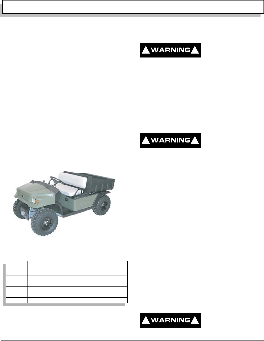
OWNER’S MANUAL
AND SERVICE GUIDE
GASOLINE POWERED
UTILITY VEHICLE
ST 4x4
STARTING MODEL YEAR 2005
E-Z-GO Division of TEXTRON, Inc. reserves the right to make design changes without obligation to make these changes on units previously sold and the infor-
mation contained in this manual is subject to change without notice.
E-Z-GO Division of TEXTRON, Inc. is not liable for errors in this manual or for incidental or consequential damages that result from the use of the material in this
manual.
TO CONTACT US
NORTH AMERICA:
TECHNICAL ASSISTANCE & WARRANTY PHONE: 1-800-774-3946, FAX: 1-800-448-8124
SERVICE PARTS PHONE: 1-888-GET-EZGO (1-888-438-3946), FAX: 1-800-752-6175
INTERNATIONAL:
PHONE: 010-1-706-798-4311, FAX: 010-1-706-771-4609
E-Z-GO DIVISION OF TEXTRON, INC., 1451 MARVIN GRIFFIN ROAD, AUGUSTA, GEORGIA USA 30906-3852

Page ii
GENERAL INFORMATION
Owner’s Manual and Service Guide
This vehicle has been designed and manufactured in the United States of America (USA) as
a ‘World Vehicle’. The Standards and Specifications listed in the following text originate in
the USA unless otherwise indicated.
The use of non Original Equipment Manufacturer (OEM) approved parts may void the
warranty.
Overfilling battery may void the warranty.
Tampering with or adjusting the governor to permit vehicle to operate at above factory
specifications will void the vehicle warranty.
When servicing engines, all adjustments and replacement components must be per original
vehicle specifications in order to maintain the United States of America Federal and State
emission certification applicable at the time of manufacture.
BATTERY PROLONGED STORAGE
All batteries will self discharge over time. The rate of self discharge varies depending on the
ambient temperature and the age and condition of the batteries.
A fully charged battery will not freeze in winter temperatures unless the temperature falls
below -75° F (-60° C).

Page iii
TABLE OF CONTENTS
Owner’s Manual and Service Guide
SAFETY ................................................................................................................ inside covers
GENERAL INFORMATION ....................................................................................................... ii
SAFETY INFORMATION ......................................................................................................... vii
WELCOME ................................................................................................................................. 1
BEFORE INITIAL USE .............................................................................................................. 1
Fig.1 Initial Service Chart ...........................................................................................................1
CAPABILITIES .......................................................................................................................... 1
TERRAIN .............................................................................................................................................................1
VEHICLE CAPACITY ..........................................................................................................................................1
MODIFICATIONS TO VEHICLE ..........................................................................................................................2
COMMON SENSE OPERATION ............................................................................................... 2
RUN-IN ....................................................................................................................................... 2
CONTROLS & INDICATORS .................................................................................................... 3
SERVICE BRAKE PEDAL ...................................................................................................................................3
Fig. 2 Service Brake Pedal ........................................................................................................3
Fig. 3 Park Brake and Indicator .................................................................................................3
CHOKE ................................................................................................................................................................3
Fig. 4 Choke ..............................................................................................................................4
IGNITION SWITCH ..............................................................................................................................................3
Fig. 5 Ignition Switch ..................................................................................................................4
DIRECTION SELECTOR .....................................................................................................................................4
Fig. 6 Direction Selector and Differential Locks .........................................................................4
2WD/4WD SELECTOR ....................................................................................................................................... 5
Fig. 7 2WD/4WD Selector ..........................................................................................................5
DIFFERENTIAL LOCK ........................................................................................................................................5
Fig. 8 Differential Lock ...............................................................................................................5
ACCELERATOR ..................................................................................................................................................6
Fig. 9 Accelerator Pedal ............................................................................................................6
FUEL .......................................................................................................................................... 6
FUEL GAUGE ......................................................................................................................................................6
Fig. 10 Fuel Tank and Gauge ....................................................................................................7
LOW OIL PRESSURE INDICATOR LIGHT .........................................................................................................6
Fig. 11 Low Pressure Oil Light ...................................................................................................7
LIGHT SWITCHES ..............................................................................................................................................7
Fig. 12 Light Switches ................................................................................................................7
12 VOLT POWER OUTLET .................................................................................................................................7
Fig. 13 Power Outlet ..................................................................................................................7
STARTING AND DRIVING ........................................................................................................ 8
STARTING VEHICLE ON A HILL ........................................................................................................................8
COASTING ..........................................................................................................................................................8
LOAD BED ................................................................................................................................. 8
TAILGATE ...........................................................................................................................................................9
MANUAL LIFT BED .............................................................................................................................................9
Fig. 14 Manual Lift Bed Release ................................................................................................9
ELECTRIC LIFT BED OPERATION ....................................................................................................................9
Fig. 15 Electric Lift Bed Switch ..................................................................................................9
WINCH ....................................................................................................................................... 9
WINCH APPLICATIONS .....................................................................................................................................9
Fig. 16 Do Not Pull at Angle ....................................................................................................10
WINCH MOUNTING ..........................................................................................................................................10
Fig. 17 Mounting Winch ...........................................................................................................11
WINCH OPERATION ........................................................................................................................................10
Fig. 18 Use Nylon Sling and Install a Damper when Winching ................................................11
Fig. 19 Winch Operation ..........................................................................................................12

Page iv Owner’s Manual and Service Guide
TABLE OF CONTENTS
TOP AND WINDSHIELD ..........................................................................................................12
TRANSPORTING VEHICLE ....................................................................................................12
TOWING ........................................................................................................................................................... 12
HAULING .................................................................................................................................12
TOWING A TRAILER ...............................................................................................................12
OPENING THE COWL (HOOD) ...............................................................................................13
Fig. 20 Unlatching Cowl .......................................................................................................... 13
DATA LABEL LOCATION .......................................................................................................13
MAINTENANCE .......................................................................................................................14
PERIODIC SERVICE SCHEDULE ...........................................................................................15
Fig. 21 Periodic Service Schedule .......................................................................................... 15
BASIC SERVICE PARTS .........................................................................................................16
Fig. 22 Basic Service Parts ..................................................................................................... 16
LIFTING THE VEHICLE ...........................................................................................................17
Fig. 23 Lifting the Vehicle ........................................................................................................ 17
OIL ............................................................................................................................................17
Fig. 24 Recommended Oil ...................................................................................................... 17
OIL LEVEL CHECK .......................................................................................................................................... 18
Fig. 25 Oil Fill and Level Check .............................................................................................. 18
OIL CHANGE .................................................................................................................................................... 18
Fig. 26 Oil Change .................................................................................................................. 18
OIL FILTER CHANGE ...................................................................................................................................... 18
Fig. 27 Oil Filter Change ......................................................................................................... 19
SPARK PLUGS ........................................................................................................................19
ALTERNATOR BELT ...............................................................................................................19
ADJUSTING BELT ............................................................................................................................................ 19
Fig. 28 Adjusting Alternator Belt ..............................................................................................20
AIR CLEANER .........................................................................................................................20
CANISTER TYPE AIR CLEANER .................................................................................................................... 20
CLEANING AIR FILTER ELEMENT ................................................................................................................. 20
Fig. 29 Air Cleaner .................................................................................................................. 20
FUEL FILTER ...........................................................................................................................20
Fig. 30 Fuel Filter .................................................................................................................... 21
LUBRICATION POINTS ...........................................................................................................21
Fig. 31 Lubrication Points ........................................................................................................ 21
BATTERY .................................................................................................................................21
BATTERY CLEANING ...................................................................................................................................... 22
Fig. 32 Cleaning Battery .......................................................................................................... 22
JUMP STARTING ....................................................................................................................22
Fig. 33 Jump Starting .............................................................................................................. 23
VEHICLE CLEANING AND CARE ..........................................................................................22
CLEANING ........................................................................................................................................................ 22
CARE PRODUCTS ........................................................................................................................................... 23
LABELS AND PICTOGRAMS .................................................................................................23
WHEELS AND TIRES ..............................................................................................................24
TIRE INSPECTION AND INFLATION .............................................................................................................. 24
REMOVAL AND INSTALLATION ..................................................................................................................... 24
Fig. 34 Wheel Tightening Sequence ....................................................................................... 24

Page v
TABLE OF CONTENTS
Owner’s Manual and Service Guide
LIGHT BULB REPLACEMENT ............................................................................................... 25
Fig. 35 Headlight Replacement ...............................................................................................25
FUSE REPLACEMENT ........................................................................................................... 25
SPARK ARRESTER ................................................................................................................ 25
Fig. 36 Cleaning Spark Arrester ..............................................................................................25
PROLONGED STORAGE ....................................................................................................... 25
FRONT AND REAR AXLES .................................................................................................... 26
CHECKING LUBRICANT LEVEL ......................................................................................................................26
Fig. 37 Checking Axle Lubricant ..............................................................................................26
TRANSFER CASE ................................................................................................................... 26
CHECKING LUBRICANT LEVEL ......................................................................................................................26
Fig. 38 Checking Transfer Case Lubricant ..............................................................................26
AIR INTAKE AND COOLING FINS ........................................................................................ 26
Fig. 39 Cleaning Air Intake and Cooling Fins ..........................................................................27
BRAKES .................................................................................................................................. 27
PERIODIC BRAKE TEST FOR HYDRAULIC BRAKES ....................................................................................27
CAPACITIES ............................................................................................................................ 27
Fig. 40 Capacities ....................................................................................................................27
HARDWARE ............................................................................................................................ 28
Fig. 41 Torque Specifications and Bolt Grades .......................................................................28
GENERAL SPECIFICATIONS.................................................................................................. 29
Fig. 42 Vehicle Dimensions ......................................................................................................31
Fig. 43 Vehicle Incline Specifications .......................................................................................31
Fig. 44 Vehicle Turning Clearance Diameter and Intersecting Aisle Clearance.......................32
VEHICLE WARRANTIES ......................................................................................................... 33
EMISSION CONTROL SYSTEM WARRANTY STATEMENT ................................................. 35
ENGINE OWNER WARRANTY POLICY ................................................................................. 35
INTERNATIONAL WARRANTY STATEMENT ........................................................................ 35
DECLARATION OF CONFORMITY (EUROPE ONLY)............................................................ 37
LABELS AND PICTOGRAMS.............................................................................................. A - 1
Fig. 45 Label Locations......................................................................................... Appendix A - 3
Fig. 46 Pictogram Definitions................................................................................ Appendix A - 4
Fig. 47 Pictogram Definitions................................................................................ Appendix A - 5
Fig. 48 Pictogram Definitions................................................................................ Appendix A - 6
Fig. 49 Pictogram Definitions................................................................................ Appendix A - 7

Page vi Owner’s Manual and Service Guide
TABLE OF CONTENTS
N
otes:

Owner’s Manual and Service Guide
SAFETY INFORMATION
Page vii
This manual has been designed to assist in maintaining the vehicle in accordance with procedures developed by the
manufacturer. Adherence to these procedures and troubleshooting tips will ensure the best possible service from the
product. To reduce the chance of personal injury or property damage, the following must be carefully observed:
GENERAL
Many vehicles are used for a variety of tasks beyond the original intended use of the vehicle; therefore, it is impossible
to anticipate and warn against every possible combination of circumstances that may occur. No warnings can take the
place of good common sense and prudent driving practices.
Good common sense and prudent driving practices do more to prevent accidents and injury than all of the warnings
and instructions combined. The manufacturer strongly suggests that all users and maintenance personnel read this
entire manual paying particular attention to the CAUTIONS and WARNINGS contained therein.
If you have any questions regarding this vehicle, contact your closest representative or write to the address on the
back cover of this publication, Attention: Product Service Department.
The manufacturer reserves the right to make design changes without obligation to make these changes on units previ-
ously sold and the information contained in this manual is subject to change without notice.
The manufacturer is not liable for errors in this manual or for incidental or consequential damages that result from the
use of the material in this manual.
This vehicle conforms to the current applicable standard(s) for safety and performance requirements.
These vehicles are designed and manufactured for off-road use. They do not conform to Federal Motor Vehicle Safety
Standards of the United States of America (USA) and are not equipped for operation on public streets. Some commu-
nities may permit these vehicles to be operated on their streets on a limited basis and in accordance with local ordi-
nances.
Refer to GENERAL SPECIFICATIONS for vehicle seating capacity.
Never modify the vehicle in any way that will alter the weight distribution of the vehicle, decrease its stability
or increase the speed beyond the factory specification. Such modifications can cause serious personal injury
or death. Modifications that increase the speed and/or weight of the vehicle will extend the stopping distance and may
reduce the stability of the vehicle. Do not make any such modifications or changes. The manufacturer prohibits and
disclaims responsibility for any such modifications or any other alteration which would adversely affect the safety of the
vehicle.
Vehicles that are capable of higher speeds must limit their speed to no more than the speed of other vehicles when
used in a golf course environment. Additionally, speed should be further moderated by the environmental conditions,
terrain and common sense.
GENERAL OPERATION
Always:
• Use the vehicle in a responsible manner and maintain the vehicle in safe operating condition.
• Read and observe all warnings and operation instruction labels affixed to the vehicle.
• Follow all safety rules established in the area where the vehicle is being operated.
• Reduce speed to compensate for poor terrain or conditions.

Owner’s Manual and Service Guide
SAFETY INFORMATION
Page viii
• Apply service brake to control speed on steep grades.
• Maintain adequate distance between vehicles.
• Reduce speed in wet areas.
• Use extreme caution when approaching sharp or blind turns.
• Use extreme caution when driving over loose terrain.
• Use extreme caution in areas where pedestrians are present.
MAINTENANCE
Always:
• Maintain the vehicle in accordance with the manufacturer’s periodic service schedule.
• Ensure that repairs are performed by those that are trained and qualified to do so.
• Follow the manufacturer’s maintenance procedures for the vehicle. Be sure to disable the vehicle before performing
any maintenance. Disabling includes removing the key from the key switch and removal of a battery wire.
• Insulate any tools used within the battery area in order to prevent sparks or battery explosion caused by shorting the
battery terminals or associated wiring. Remove the battery or cover exposed terminals with an insulating material.
• Use specified replacement parts. Never use replacement parts of lesser quality.
• Use recommended tools.
• Determine that tools and procedures not specifically recommended by the manufacturer will not compromise the
safety of personnel nor jeopardize the safe operation of the vehicle.
• Support the vehicle using wheel chocks and jack stands. Never get under a vehicle that is supported by a jack. Lift
the vehicle in accordance with the manufacturer’s instructions.
• Empty the fuel tank or plug fuel hoses to prevent fuel leakage.
• Maintain the vehicle in an area away from exposed flame or persons who are smoking.
• Be aware that a vehicle that is not performing as designed is a potential hazard and must not be operated.
• Test drive the vehicle after any repairs or maintenance. All tests must be conducted in a safe area that is free of both
vehicular and pedestrian traffic.
• Replace damaged or missing warning, caution or information labels.
• Keep complete records of the maintenance history of the vehicle.
The manufacturer cannot anticipate all situations, therefore people attempting to maintain or repair the vehicle must
have the skill and experience to recognize and protect themselves from potential situations that could result in severe
personal injury or death and damage to the vehicle. Use extreme caution and, if unsure as to the potential for injury,
refer the repair or maintenance to a qualified mechanic.

Owner’s Manual and Service Guide
SAFETY INFORMATION
Page ix
VENTILATION
Always store gasoline vehicles in a well ventilated area. Ventilation prevents gasoline fumes from accumulating.
Never fuel a vehicle in an area that is subject to flame or spark. Pay particular attention to natural gas or propane water
heaters and furnaces.
Never work around or operate a vehicle in an environment that does not ventilate exhaust gases from the area. Carbon
monoxide is a dangerous gas that can cause unconsciousness and is potentially lethal.

Owner’s Manual and Service Guide
SAFETY INFORMATION
Page x
Notes:

SAFETY INFORMATION
Page xi
Owner’s Manual and Service Guide
Read all of manual to become thoroughly familiar with this vehicle. Pay particular attention to all Notes, Cautions and Warnings
GENERAL
The following text is provided as recommended by part II
of SAE J2258 DEC 2003. E-Z-GO strongly endorses the
contents of this specification.
B.1 PART II
FOR THE CONTROLLING PARTY
B.1.1 Maintenance and Operations
B.1.1.1 Introduction
B.1.1.1.1 Like other machines, light utility vehicles
can cause injury if improperly used or maintained. Part II
contains broad safety practices applicable to vehicle
operations. Before operation, the controlling party shall
follow such additional specific safety practices as may
reasonably be required for safe operation.
B.1.1.1.2 Safety Survey-The controlling party shall
perform a safety survey of their premises periodically,
and as conditions warrant, identify areas where vehicles
should not be operated and to identify possible hazards.
(a) Steep Grade-In areas where steep grades exist,
vehicle operation should be restricted to the designated
vehicle's pathways where possible, and shall be identi-
fied with a suitable warning giving the following informa-
tion: “Warning, steep grade, descend slowly.”
(b) Wet Areas-Wet areas could cause a vehicle to lose
traction and could affect steering, stability and braking.
(c) Sharp Turns, Blind Corners, Bridge Approaches-
Sharp turns, blind spots, bridge approaches, and other
potentially hazardous areas shall be identified with a suit-
able warning to the operator of the nature of the hazard
and stating the proper precautions to be taken to avoid
the hazard.
(d) Loose Terrain-Loose terrain could cause a vehicle
to lose traction and could affect steering, stability, and
braking.
B.1.1.1.3 Utility Vehicle/Pedestrian Interference
Areas-Areas where pedestrian and vehicle traffic could
interfere should be avoided by rerouting the vehicle or
the pedestrian traffic to eliminate the interference. If elim-
ination of the interference is not possible or is highly
impractical, signs shall be erected warning pedestrians
and vehicle operators of traffic conditions and to use cau-
tion.
B.1.1.1.4 The controlling party shall train vehicle
operators to adhere strictly to the operating instructions
stated in vehicle operator's manual and those additional
operating instructions provided by controlling party.
B.1.1.1.5 The controlling party shall survey specific
operating conditions and environment, establish safety
practices, and train vehicle operators to comply with
these practices.
B.1.1.2 Operation Experience has shown that vehi-
cles which comply with the provisions stated in 7.8 are
stable when properly operated in accordance with spe-
cific safety rules and practices established to meet actual
operating terrain and conditions. However, improper
operation, faulty maintenance, or poor housekeeping
may contribute to a condition of instability and defeat the
purpose of the standard. Some conditions which could
affect stability are failure of the operator to follow safety
practices, surface conditions, grade, speed, loading,
braking, turning, improper loads, towing, attachments,
dynamic forces, and the judgment exercised by the vehi-
cle operator.
B.1.1.3 Nameplates, Markings, Capacity, And Mod-
ifications.
B.1.1.3.1 The controlling party shall maintain in a legi-
ble condition all nameplates, warnings, and instructions
which are supplied by the vehicle manufacturer.
B.1.1.3.2 The controlling party shall not perform any
modification or addition which affects capacity or safe
operation, or make any change not in accordance with
the vehicle manual(s) without the vehicle manufacturer's
prior written authorization. Where authorized modifica-
tions have been made, the controlling party shall ensure
that capacity, operation, warning, and maintenance
instruction plates, tags, or decals are changed accord-
ingly.
B.1.1.3.3 As required under B.1.1.3.1 or B.1.1.3.2,
the vehicle manufacturer shall be contacted to secure
new nameplates, warnings, or instructions which shall
then be affixed in their proper place on the vehicle.
B.1.1.4 Fuel Handling
B.1.1.4.1 The controlling party shall supervise the
handling of liquid fuels (when used) to be certain that it is
in accordance with appropriate sections of ANSI/NFPA
505 and ANSI/NFPA 30 or as required by local ordi-
nance.

SAFETY INFORMATION
Page xii Owner’s Manual and Service Guide
Read all of manual to become thoroughly familiar with this vehicle. Pay particular attention to all Notes, Cautions and Warnings
B.1.1.4.2 The controlling party shall supervise the
handling of liquefied petroleum gas fuels (when used) to
be certain it is in accordance with appropriate sections of
ANSI/NFPA 505 and ANSI/NFPA 58 or as required by
local ordinance.
B.1.1.5 Charging Storage Batteries
B.1.1.5.1 The controlling party shall require battery-
charging procedures to be in accordance with appropri-
ate sections of ANSI/NFPA 505, ISO 3691, or local ordi-
nance and meet any other requirements such as OSHA.
B.1.1.5.2 The controlling party shall periodically
review procedures to be certain that appropriate sections
of ANSI/ NFPA 505 or local ordinance and OSHA are
strictly complied with, and shall familiarize vehicle opera-
tors with it.
B.1.1.6 Lighting For Operating Areas
B.1.1.6.1 The controlling party, in accordance with his
responsibility to survey the environment and operating
conditions, shall determine if the vehicle requires lights
and, if so, shall equip the vehicle with appropriate lights
in accordance with the vehicle manufacturer's recom-
mendations.
B.1.1.7 Warning Device(s)
B.1.1.7.1 The controlling party shall make periodic
inspections of the vehicle to be certain that the sound-
producing and visual device(s), if so equipped, are main-
tained in good operating conditioning condition.
B.1.1.7.2 The controlling party shall determine if oper-
ating conditions require the vehicle to be equipped with
additional sound-producing and/or visual devices com-
patible with the vehicle manufacturer's recommenda-
tions, and be responsible for providing and maintaining
such devices, in accordance with the vehicle manufac-
turer's recommendations.
B.1.1.8 Safety Interlocks
B.1.1.8.1 The controlling party shall make periodic
inspections of the vehicle to be certain that the safety
interlock system, if so equipped, is operating properly.
B.2 Operating Safety Rules and
Practices
B.2.1 Operator Qualifications
B.2.1.1 Only persons who are trained in the proper
operation of the vehicle shall be authorized to operate
the vehicle. Operators shall be qualified as to visual,
auditory, physical, and mental ability to safely operate the
vehicle according to Section 5 and all other applicable
parts of this document and vehicle operator's manual.
B.2.2 Operator’s Training
B.2.2.1 The controlling party shall develop and con-
duct an operator training program.
B.2.2.2 Successful completion of the operator train-
ing program by the operator shall be required before
operation of the vehicle. The program shall be presented
in its entirety to all new operators and not condensed for
those claiming previous experience.
B.2.2.3 The controlling party should include, as a
minimum, in the operator training program the following:
(a) Instructional material provided by the vehicle man-
ufacturer, including vehicle operator's manual.
(b) Emphasis on safety of passengers, vehicle opera-
tor, and other persons.
(c) Safe loading practice, including securing material
loads.
(d) General safety rules contained within this docu-
ment and the additional specific rules determined by the
controlling party in accordance with this document, and
why they were formulated.
(e) Introduction of equipment, control locations, and
functions, and explanation of how they work when used
properly and the consequences of improper use; expla-
nation of surface conditions, grade, and other conditions
of the environment which could affect vehicle operation.
(f) Operator competency evaluations.
B.2.3 Operator Responsibility
B.2.3.1 Read and follow operator's manual.
B.2.3.2 Do not operate vehicle under the influence of
drugs or alcohol.
B.2.3.3 Safeguard the pedestrians at all times. Do
not drive vehicle in a manner that could endanger other
persons.

SAFETY INFORMATION
Page xiii
Owner’s Manual and Service Guide
Read all of manual to become thoroughly familiar with this vehicle. Pay particular attention to all Notes, Cautions and Warnings
B.2.3.4 Riding on the vehicle by persons other than
the operator is authorized only on seat(s) provided by the
vehicle manufacturer. All parts of each person's body
shall remain within the plan view outline of the vehicle
while the vehicle is in motion.
B.2.3.5 When a vehicle is to be left unattended, stop
vehicle, apply the parking brake, turn off the control or
ignition circuit, and remove the key if provided. Block the
wheels if vehicle is on an incline.
B.2.3.6 Maintain a safe distance from potential haz-
ards.
B.2.3.7 Use only approved vehicles in hazardous
locations, as defined in the appropriate safety standards.
B.2.3.8 Report all accidents involving personnel,
building structures, and equipment.
B.2.3.9 Do not add to, or modify, the vehicle.
B.2.3.10 Slow down or stop, as conditions dictate, and
activate a sound-producing warning device, if so
equipped, at intersections and when visibility is
obstructed at other locations.
B.2.3.11 Ascend or descend grades slowly, avoid
turning if possible; normally travel straight up and down.
B.2.3.12 Under all travel conditions, operate vehicle at
speeds that will permit it to be brought to a stop in a safe
manner.
B.2.3.13 Use caution and slow down when approach-
ing or on wet or slippery surfaces, loose or unfamiliar ter-
rain.
B.2.3.14 Avoid sudden starts, stops, turns, or direction
reversals so as not to shift the load, endanger passen-
gers, or lose control of the vehicle.
B.2.3.15 Do not operate vehicle in a dangerous man-
ner, such as stunt driving or horseplay.
B.2.3.16 Avoid running over loose objects, potholes,
and bumps.
B.2.4 Loading
B.2.4.1 Refer to operator's manual for loading
instructions.
B.2.4.2 Transport only stable and safely arranged
loads secured to prevent movement. Avoid loads which
cannot be centered.
B.2.4.3 Transport only loads within the gross vehicle
weight capacity.
B.2.4.4 Avoid material loads exceeding the physical
dimensions of the vehicle or as specified by the vehicle
manufacturer.
B.2.5 Operator Care of Light Utility
Vehicles
B.2.5.1 Follow Operator's Manual.
B.2.5.2 At the beginning of each operating period
during which the vehicle will be used, the operator shall
check the vehicle condition and inspect the tires, warning
devices, safety interlocks, lights, battery(s), fuel system,
speed and directional controllers, brakes, and steering
mechanism. If the vehicle is found to be in need of repair,
or in any way unsafe, the matter shall be reported imme-
diately to the controlling party and the vehicle shall not be
operated until it has been restored to safe operating con-
dition.
B.2.5.3 If during operation the vehicle becomes
unsafe in any way, the matter shall be reported immedi-
ately to the controlling party, and the vehicle shall not be
operated until it has been restored to safe operating con-
dition.
B.2.5.4 Repairs and adjustments shall only be per-
formed by specifically trained and authorized persons.
B.3 Maintenance Practices
B.3.1 Maintenance Procedures
B.3.1.1 Maintenance and inspection of all vehicles
shall be performed in conformance with the vehicle man-
ufacturer's recommendations and the following practices,
if applicable. Only trained and authorized personnel shall
be permitted to maintain, repair, adjust, and inspect vehi-
cles.
(a) A scheduled preventive maintenance, lubrication,
and inspection system shall be followed.
(b) Before undertaking maintenance or repair, follow
the vehicle manufacturer's recommendations for immobi-
lizing the vehicle.
(c) Chock wheels and block chassis before working
underneath it.
(d) Before disconnecting any part of the fuel system of
a gasoline-powered vehicle, be sure shutoff valve, if so
equipped, is closed, and run engine until fuel system is
depleted, engine stops running, and is allowed to cool.
Before disconnecting any part of the engine fuel system
of a diesel-powered vehicle, be sure shutoff valve, if so

SAFETY INFORMATION
Page xiv Owner’s Manual and Service Guide
Read all of manual to become thoroughly familiar with this vehicle. Pay particular attention to all Notes, Cautions and Warnings
equipped, is closed, following vehicle manufacturer's rec-
ommended practice.
(e) Before disconnecting any part of the fuel system of
LP/CNG powered vehicles, close the fuel cylinder valve
and run the engine until fuel in the system is depleted,
the engine stops running, and is allowed to cool
(f) Disconnect battery(s).
(g) Operation to check performance of the vehicle
shall be conducted in an authorized area where suitable
conditions exist, free of vehicular and pedestrian traffic.to
cool.
(h) Before returning the vehicle to service, follow the
vehicle manufacturer's recommended procedures.
(i) Avoid fire hazards and have fire protection equip-
ment present in the work area. Do not use an open flame
to check level or leakage of fuel, battery electrolyte, or
coolant.
(j) Properly ventilate the work area in accordance with
applicable regulations or local ordinances.
(k) Handle fuel cylinders carefully. Physical damage,
such as dents, scrapes, or gouges, may dangerously
weaken cylinders and make them unsafe for use.
(l) Brake mechanisms, steering mechanisms, speed
and directional control mechanisms, warning devices,
electrical systems, governors, guards, exhaust system,
and safety devices shall be inspected regularly and
maintained in accordance with the vehicle manufac-
turer's recommended procedures.
(m) Vehicles or devices designed and approved for
hazardous area operation shall be inspected to ensure
that maintenance preserves the original approved oper-
ating features.
(n) Fuel systems shall be checked for leaks and condi-
tion of parts. If a leak is found, action shall be taken to
prevent the use of the vehicle until the cause of the leak
has been repaired.
(o) The vehicle manufacturer's capacity, operation,
and maintenance instruction plates, tags, and safety
labels shall be maintained in legible condition.
(p) Batteries, motors, speed and directional control-
lers, limit switches, protective devices, electrical conduc-
tors/insulators, and connections shall be inspected and
maintained in accordance with vehicle manufacturer's
recommended procedures.
(q) Vehicles shall be kept in a clean condition to mini-
mize fire hazards and facilitate the detection of compo-
nents needing service.
(r) Hydraulic systems, if so equipped, shall be
checked for leaks and condition of parts. Keep body and
hands away from pin hole leaks or nozzles that eject
hydraulic fluid under high pressure. Use paper or card-
board, not hands, to search for leaks.
(s) Modifications and additions which affect capacity
and safe machine operation shall not be performed with-
out vehicle manufacturer's prior written authorization.
Where authorized modifications have been made, the
controlling party shall ensure that capacity, operation,
warning, and maintenance instruction plates, tags, and
safety labels are changed accordingly.
(t) Care shall be taken to ensure that all replacement
parts are interchangeable with the original parts and of a
specification at least equal to that provided in the original
equipment.
End of SAE J2258 DEC 2003, Part II
OPERATION AND SERVICE INFORMATION
Page 1
Owner’s Manual and Service Guide
Read all of manual to become thoroughly familiar with this vehicle. Pay particular attention to all Notes, Cautions and Warnings
WELCOME
Thank you for purchasing this utility vehicle. Before driv-
ing vehicle, we ask you to spend some time reading this
Owner’s Manual and Service Guide and the Owner’s
Manual provided by Honda Motor Co., Ltd. These manu-
als contain information to assist you in safe operation of
vehicle. They will also assist you in maintaining vehicle.
Some illustrations may show items that are optional.
Most service procedures in this guide can be accom-
plished using common automotive hand tools. Other-
wise, contact your service representative to schedule
maintenance performed by a technician. Any servicing
must be done per the Periodic Service Schedule found in
this manual and the Maintenance Schedule found in the
engine manual.
Service Parts Manuals, Technician’s Repair and Service
Manuals and engine Repair Manuals are available from a
local Distributor, an authorized Branch or the Service
Parts Department. When ordering parts or requesting
information for your vehicle, provide vehicle model, serial
number and manufacture date code.
BEFORE INITIAL USE
Read, understand and follow safety label on driver side
fender well (Ref Appendix A). Be sure you understand
how to safely operate vehicle and its equipment.
Maintaining good performance depends, to a large
extent, on owner/operator.
To reduce possibility of
severe injury or death,
do not use vehicle
improperly such as engaging in horseplay or attempt-
ing to perform tasks for which it is not designed.
This vehicle is a utility vehicle. It is NOT a toy or an all
terrain vehicle (ATV).
Before new vehicle is put into operation, items shown in
INITIAL SERVICE CHART must be performed (Ref. Fig.
1 on page 1).
CAPABILITIES
TERRAIN
To reduce possibility of
severe injury or death
while driving, be aware
of the following:
Environmental hazards such as steep slopes,
overhanging limbs, etc.
Danger of fire when vehicle is operated over dry
combustible organic material.
Vehicle is designed for: improved roads (not public high-
ways), established trails, open terrain free from stumps,
large rocks or holes, crossing water no deeper than 8
inches (20 cm).
Slow down when: traveling unfamiliar terrain, cresting a
hill.
Be aware of hazards such as: steep slopes, overhanging
limbs, danger of fire when vehicle is operated over dry
combustible organic material.
On steep slopes: do not turn vehicle or stop and turn
around, always travel straight up and down, control
speed with service brake when going downhill.
Vehicle stopping distance increases: when driving on wet
grass, dirt roads or loose surfaces, when crossing
streams or bodies of water that soak the brakes.
Remember to lightly apply brakes and use friction to dry
braking surfaces.
VEHICLE CAPACITY
To reduce possibility of
severe injury or death
due to the variety of
ITEM SERVICE OPERATION
Seats Remove protective plastic covering
Brakes Check operation and brake fluid level
Tires Check air pressure (see SPECIFICATIONS)
Fuel Fill tank with correct fuel
Engine Check oil level
Keys Record key number and store in a safe location
Fig. 1 Initial Service Chart
Ref Int 1
! !
! !
! !
OPERATION AND SERVICE INFORMATION
Page 2 Owner’s Manual and Service Guide
Read all of manual to become thoroughly familiar with this vehicle. Pay particular attention to all Notes, Cautions and Warnings
ways the vehicle may be used, it is important the
operator consider any potential hazards before use to
prevent serious injury or death.
See GENERAL SPECIFICATIONS section of this man-
ual for load and seating capacity.
Never carry passengers in load bed.
The weight of driver and passenger plus any options or
accessories must be deducted from total payload rating
to determine load bed capacity.
Stopping distance increases as vehicle load increases.
Load weight can be misleading. Loads consisting of dry
sand, fertilizer, sod, etc. will, when wet, grossly overload
vehicle and increase potential for roll over and vehicle
damage.
Towing a loaded trailer reduces capacity of vehicle load
bed. (Ref. TOWING A TRAILER on page 12)
MODIFICATIONS TO VEHICLE
Changes to weight distri-
bution or center of gravi-
ty may make vehicle
unstable or prone to roll over which could result in
injury or death to operator or passenger.
Do not modify vehicle in any manner that will change
weight distribution.
Changes to weight distribution or center of gravity may
make it unstable or prone to roll over which could result
in injury or death to operator or passenger.
Do not tamper with governor. It is set for maximum safe
vehicle speed.
Do not tamper with exhaust system. It is matched with
engine for optimum performance.
Removal of muffler or other modifications to exhaust sys-
tem will: annoy others, not improve performance of vehi-
cle, increase possibility of starting a fire.
COMMON SENSE OPERATION
To reduce possibility of
severe injury or death to
operator, passenger or
bystanders, do not operate vehicle improperly and/or
irresponsibly.
If vehicle is operated improperly and/or irresponsibly,
severe injury or death to operator, passenger or bystand-
ers can occur.
All operators should possess a valid driver’s license.
Children may not have the skill, judgement or strength to
operate this or similar vehicles and should not be permit-
ted to do so.
Alcohol, drugs and many over-the-counter medications
reduce ability of driver to operate vehicle safely. Always
review side effects of any medication with a doctor or
pharmacist before operating vehicle.
If the vehicle is to be used in areas where steep slopes,
overhanging limbs or other adverse conditions may be
encountered, protective clothing and an approved motor-
cycle helmet are recommended for both operator and
passenger.
Plan carefully before using vehicle to go significant dis-
tances over questionable terrain. Remember that a one
hour drive may take many hours to walk out should vehi-
cle run out of fuel or be stranded by becoming stuck on
unsuitable terrain.
Respect private property and comply with all local laws
and regulations governing use of utility vehicles.
RUN-IN
Check for oil or fuel leaks that could have developed in
shipment from factory. Avoid full throttle starts and rapid
acceleration until engine has achieved operating temper-
ature.
All engines consume more oil than normal during the first
hours of operation. As internal moving parts are run-in,
oil consumption should gradually decrease until rate of
consumption stabilizes.
Check oil level See OIL LEVEL CHECK on page 18. Add
oil if level on dipstick is at lower hole.
Do not overfill engine. Too much oil
may cause smoking or allow oil to enter
the air filter enclosure.
Both the oil dipstick and fill cap must be in
place before operating the engine. Failure to
install the dipstick and fill cap will result in oil becoming contam-
inated and/or being discharged into the engine compartment.
Oil should be changed, while engine is warm, at end of
run-in period (Ref. Periodic Service Schedule on page
15).
! !
! !
OPERATION AND SERVICE INFORMATION
Page 3
Owner’s Manual and Service Guide
Read all of manual to become thoroughly familiar with this vehicle. Pay particular attention to all Notes, Cautions and Warnings
CONTROLS & INDICATORS
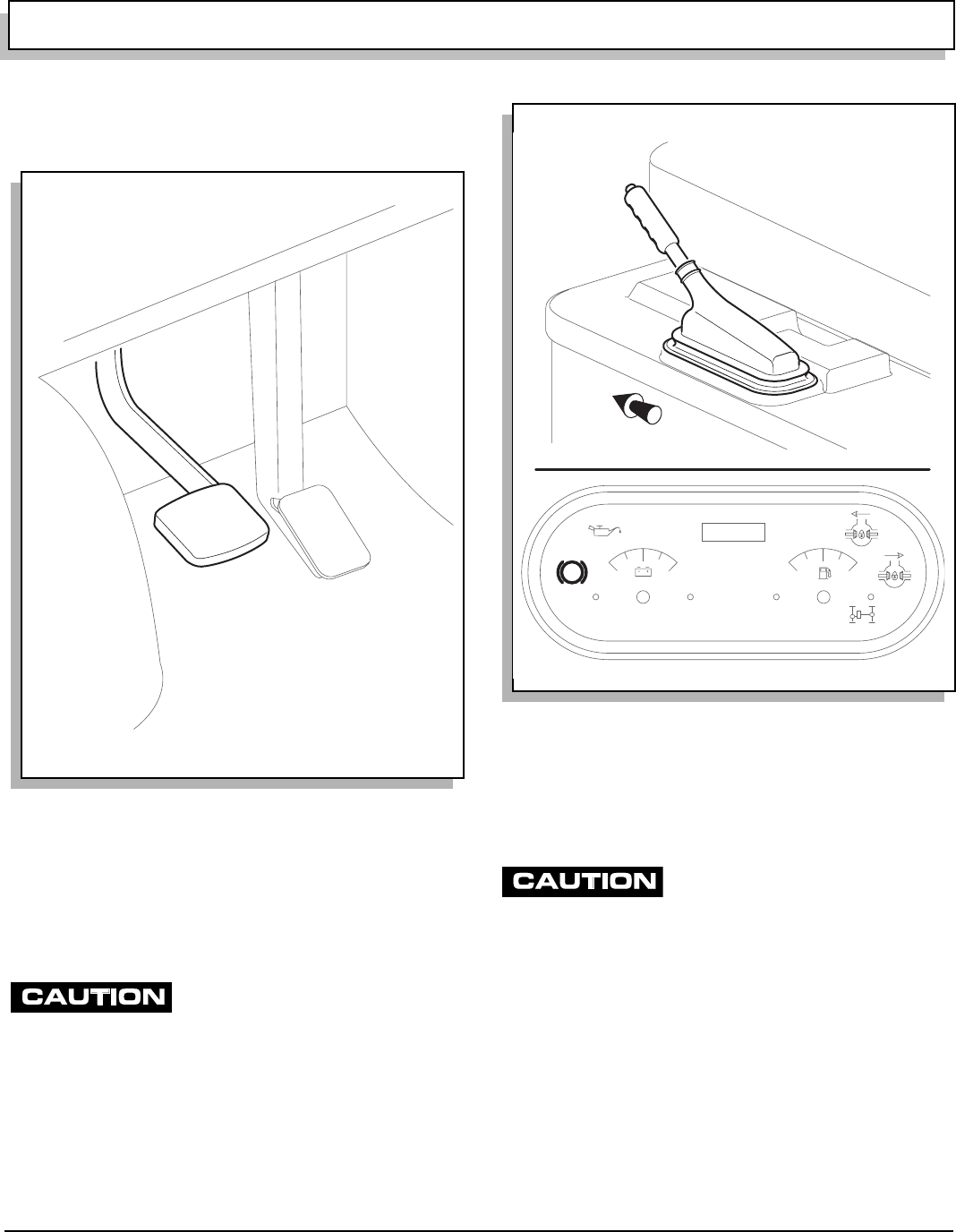
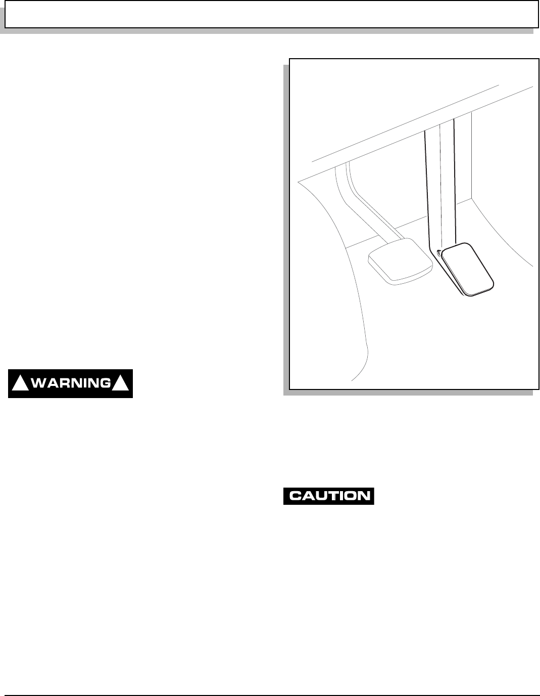
SERVICE BRAKE PEDAL
The service brake is a hydraulic front disc/rear drum
brake system.
Push foot operated service brake pedal to activate wheel
brakes, slowing or stopping vehicle (Ref. Fig. 2 on page
3).
PARKING BRAKE
Drive vehicle with park brake fully
released. Failure to do so will prema-
turely wear rear brakes.
The park brake is a mechanical system using rear drum
service brakes.
To engage, pull park brake handle up. An indicator light
will illuminate in gauge cluster reminding operator to
release park brake before driving (Ref. Fig. 3 on page 3).
To disengage, pull up slightly and push in release button
at end of handle, then fully lower park brake handle.
CHOKE
Starting a cold engine may require use of choke. To use,
pull choke knob out and hold while starting engine (Ref.
Fig. 4 on page 4). Once started and engine begins to
warm, release choke knob.
Do not allow starter to operate continu-
ously for more than 10 seconds. Allow
30 seconds between starting attempts. If vehicle does not start
on third attempt, turn key switch off, set park brake and deter-
mine cause of problem.
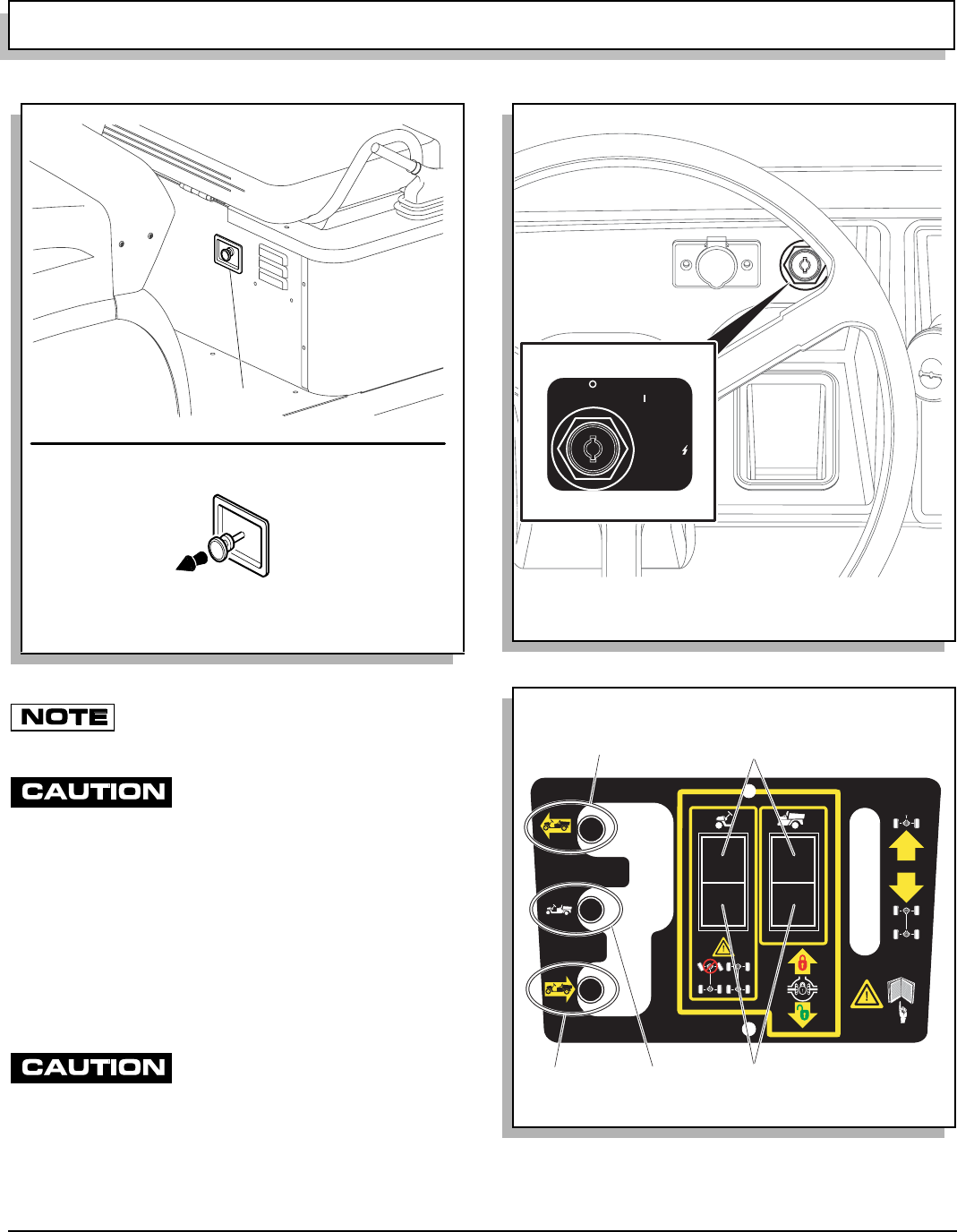
IGNITION SWITCH
Ignition switch has three positions: ‘OFF’, ‘ON’ and
‘START’ (Ref. Fig. 5 on page 4).
Insert key into switch and turn clockwise to ‘ON’ to
enable starting system.
Continue to turn clockwise to “START” to activate starter.
Once engine starts, release key allowing return to ‘ON’.
To prevent inadvertent operation of vehicle when left
unattended, turn key to ‘OFF’ position and remove key.
Fig. 2 Service Brake Pedal
Ref Sbp 1 Fig. 3 Park Brake and Indicator
Front of Vehicle
P
HOURS
8 16 0 4/4
Ref Pbh 2
OPERATION AND SERVICE INFORMATION
Page 4 Owner’s Manual and Service Guide
Read all of manual to become thoroughly familiar with this vehicle. Pay particular attention to all Notes, Cautions and Warnings
If vehicle is equipped with factory installed cus-
tom accessories, some accessories remain
operational with key switch in ‘OFF’ position.
To prevent draining the battery, always
place differential lock switches in the
‘unlocked’ position, turn the key switch to ‘off’ and remove the
key.
If one or both of the differential locks is engaged and the
key left in the ‘on’ position, the differential lock sole-
noid(s) will be activated (Ref. Fig. 6 on page 4) and (Ref.
Fig. 8 on page 5). Over time the solenoids will drain the
battery to a point where the vehicle will be unable to be
started.
DIRECTION SELECTOR
To reduce possibility of drivetrain dam-
age, vehicle must completely stop
before moving direction selector (Ref. Fig. 6 on page 4).
Direction selector offers choice of three positions: for-
ward, neutral and reverse (Ref. Fig. 6 on page 4).
Selector must be in neutral to start engine. Always bring vehicle to a complete stop before changing
selection.
Fig. 4 Choke
R
ef Chk 4
Choke
Pull
Out
Fig. 5 Ignition Switch
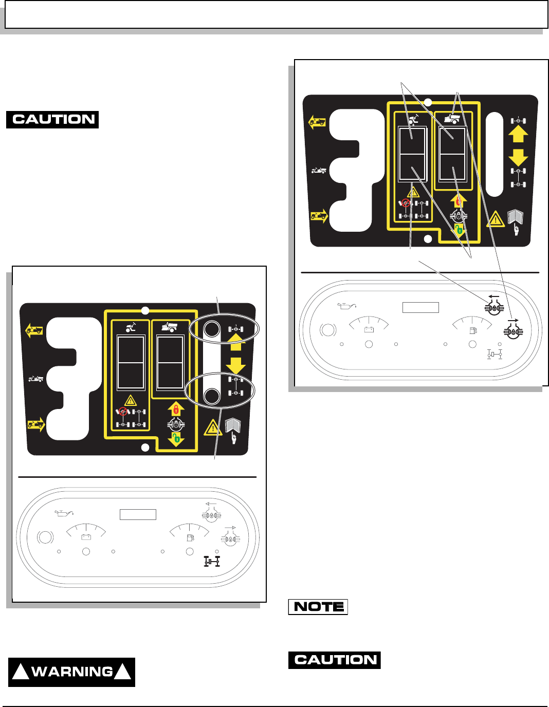
Fig. 6 Direction Selector and Differential Locks
Ref Kes 5
OFF
ON
START
73767G01
73777G01
Ref Dsl 5
Neutral Disengaged
Forward Engaged
Reverse
OPERATION AND SERVICE INFORMATION
Page 5
Owner’s Manual and Service Guide
Read all of manual to become thoroughly familiar with this vehicle. Pay particular attention to all Notes, Cautions and Warnings
Place direction selector in forward and set park brake
when leaving vehicle unattended.
2WD/4WD SELECTOR
To reduce possibility of drivetrain dam-
age, vehicle must completely stop
before switching between two wheel and four wheel drive.
This lever allows choice of two wheel or four wheel drive
(Ref. Fig. 7 on page 5).
Always bring vehicle to a complete stop before changing
selection.
When four wheel drive is selected, an indicator light in
gauge cluster will illuminate to verify engagement.
Vehicle should be left in two wheel drive when unat-
tended.
DIFFERENTIAL LOCK
To reduce possibility of
severe injury or death
from loss of control
while vehicle is in motion, do not engage front differ-
ential lock while turning steering wheel. Lock engage-
ment may abruptly force steering wheel to center
causing loss of grip on wheel.
Front and rear differentials are equipped with electrically
actuated locks (Ref. Fig. 8 on page 5). With a differential
unlocked, if one tire looses traction, the vehicle will likely
become stuck. With a differential locked, power is dis-
tributed to both tires at all times and greatly increases
traction. Locks are not intended to be engaged at all
times. They are intended to free or prevent vehicle from
being stuck as terrain demands, ideally for short runs at
slow speeds. Always disengage differential locks as ter-
rain and conditions allow.
Differential locks should only be used when
additional traction is required. Continued use of
rear differential lock may cause excessive wear to tires. Contin-
ued use of front differential lock may increase steering effort.
Vehicle must be completely stopped
before engaging or disengaging differ-
ential lock. Failure to stop may damage differential.
Fig. 7 2WD/4WD Selector
73777G01
Two Wheel Drive
Four Wheel Drive
Ref 4wd 1
P
HOURS
8 16 0 4/4
! !
Fig. 8 Differential Lock
73777G01
Ref Dif 1
P
HOURS
8 16 0 4/4
Rear Differential
Lock Switch
Front Differential
Lock Switch Disengaged
Engaged
OPERATION AND SERVICE INFORMATION
Page 6 Owner’s Manual and Service Guide
Read all of manual to become thoroughly familiar with this vehicle. Pay particular attention to all Notes, Cautions and Warnings
To prevent draining the battery, always place differential lock
switches in the ‘unlocked’ position, turn the key switch to ‘off’
and remove the key.
To engage rear differential lock, stop vehicle and push
upper portion of rear differential lock switch. To engage
front and rear differential lock, stop vehicle and push
upper portion of both differential lock switches. Indicator
lights in gauge cluster illuminate to remind operator when
locks are engaged.
To disengage differential locks, stop vehicle and push
lower portion of switches. After unlocking, the differential
may remain locked if driving is resumed in a straight line.
This is a normal occurrence caused by pressure remain-
ing against the gears and not allowing the locking mech-
anism to release. To avoid this, simply turn vehicle as
acceleration begins or accelerate in reverse.
ACCELERATOR
With engine running, push accelerator pedal to acceler-
ate in direction selected (Ref. Fig. 9 on page 6). Release
pedal to slow vehicle and engine will idle. To stop vehicle
quickly, apply service brake.
FUEL
To reduce possibility of
severe injury or death
from improper fuel han-
dling:
Do not smoke near the fuel tank.
Do not refuel near open flame or electrical items,
including cellular phones, which could produce a
spark.
Never fill a gas can in the bed of a vehicle. Static
discharge could ignite gasoline vapor and cause
an explosion.
Always handle gasoline in a well ventilated area.
Always wear eye protection to protect against
splashed fuel and fuel vapors.
Always allow adequate space for the expansion of
gasoline. Leave at least 1" (2.5 cm) space below
bottom of filler neck.
Inspect fuel cap, tank and other components for
leaks or deterioration that could cause a hazard-
ous condition.
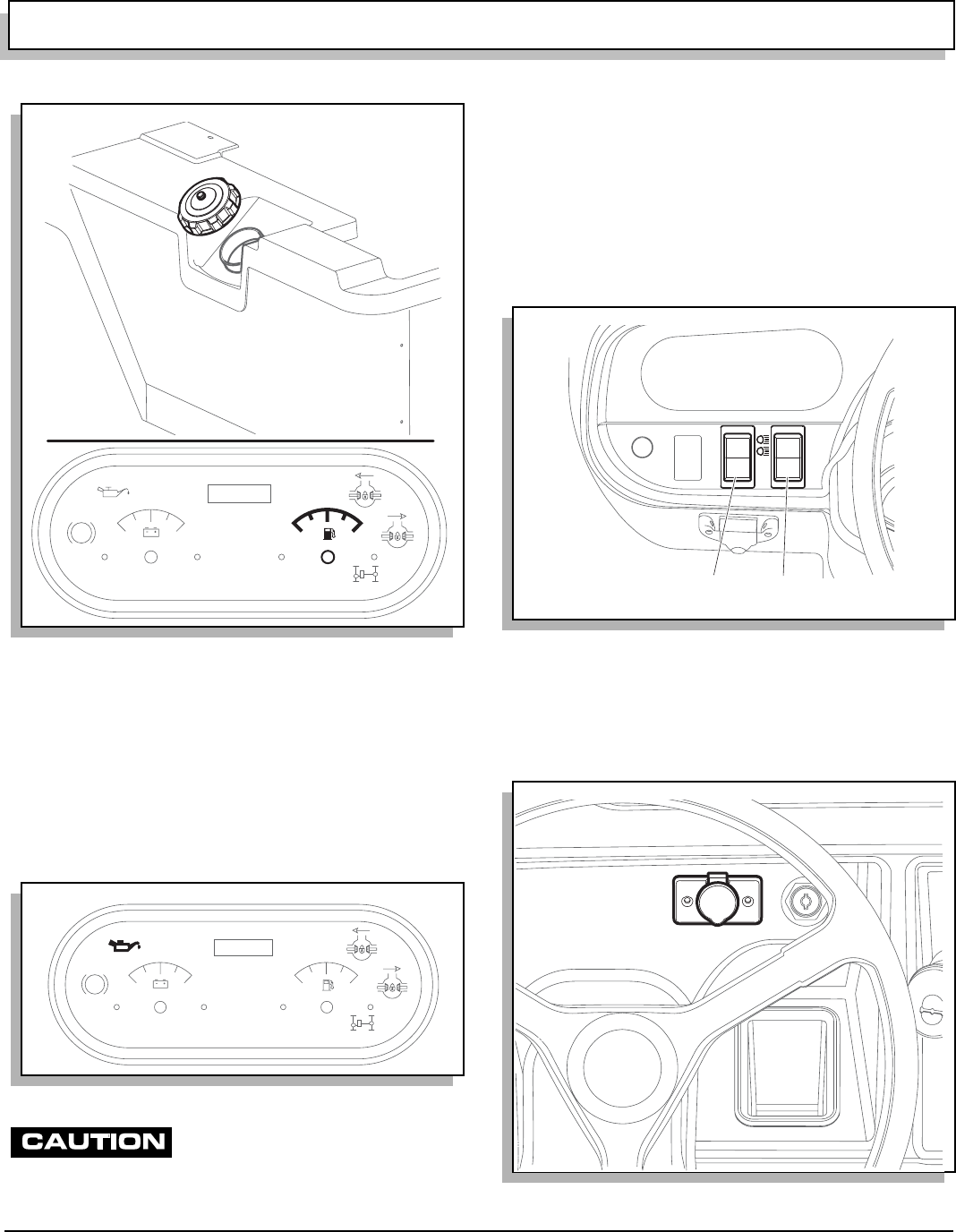
Fuel cap is located on passenger side panel of vehicle
beside seat (Ref. Fig. 10 on page 7). Fuel tank is located
under passenger side of seat. Fill tank with fresh, clean,
automotive grade gasoline. High altitude or heavy use/
load applications may benefit from higher octane gaso-
line.
Do not use gasoline which contains Methanol.
Some fuels, called oxygenated or reformu-
lated gasoline, are gasoline blended with
alcohols or ethers. Excessive amounts of these blends can damage the
fuel system or cause performance problems. If any undesirable operat-
ing symptoms occur, use gasoline with a lower percentage of alcohol or
ether.
Do not overfill the fuel tank. Allow adequate space for the expan-
sion of gasoline. Leave at least 1" (2.5 cm) space below bottom
of filler neck.
FUEL GAUGE
An electric fuel gauge is located left of steering wheel in
gauge cluster (Ref. Fig. 10 on page 7). It indicates
amount of fuel in tank.
! !
Fig. 9 Accelerator Pedal
Ref Acl 1
OPERATION AND SERVICE INFORMATION
Page 7
Owner’s Manual and Service Guide
Read all of manual to become thoroughly familiar with this vehicle. Pay particular attention to all Notes, Cautions and Warnings
LOW OIL PRESSURE INDICATOR LIGHT
Low oil pressure indicator light is located in gauge cluster
at left of dash panel. Indicator light is activated if oil pres-
sure drops below 1.5 psi (.11 kg/cm2) (Ref. Fig. 11 on
page 7). Check oil level See ‘OIL LEVEL CHECK’ on
page 18. If oil level is between ADD and FULL mark on
dipstick, a mechanical problem exists within engine and
vehicle must not be driven. Contact a local Distributor
or authorized Branch.
To reduce possibility of engine damage,
do not operate engine until oil pressure
is corrected. Do not overfill engine. Too much oil may cause
smoking or allow oil to enter air filter enclosure.
If oil level is below ADD mark on dipstick, add oil to bring
level to FULL mark. Drive vehicle a short distance and
check oil pressure. If oil pressure light does not come on,
continue to use vehicle.
LIGHT SWITCHES
Headlight switch is located to left of steering wheel on
dash panel (Ref. Fig. 12 on page 7). Headlights operate
independently of ignition switch.
Accessory switch is located to right of headlight switch. It
may operate accessory items, (if equipped), indepen-
dently of headlights and ignition switch.
12 VOLT POWER OUTLET
Fig. 10 Fuel Tank and Gauge
Fig. 11 Low Pressure Oil Light
P
HOURS
8 16
04/4
Ref Ftl 4
P
HOURS
816 04/4
Ref Opl 1
Fig. 12 Light Switches
Fig. 13 Power Outlet
Ref Lsw 1
Headlight Accessory
Switch
Re
f
Pow 2

OPERATION AND SERVICE INFORMATION
Page 8 Owner’s Manual and Service Guide
Read all of manual to become thoroughly familiar with this vehicle. Pay particular attention to all Notes, Cautions and Warnings
Overuse of accessories may drain bat-
tery and leave insufficient reserve to
start vehicle.
A 12 volt power outlet, rated at 15 amps, is located left of
ignition switch (Ref. Fig. 13 on page 7). It provides con-
stant power for accessories equipped with a 12 volt plug
STARTING AND DRIVING
To reduce possibility of
roll-back which could
result in severe injury or
vehicle damage, do not release service brake until
engine has started.
To operate vehicle:
•Apply service brake.
•Place direction selector in neutral.
•Insert key into ignition switch and turn it to ‘ON’
position.
•Apply choke if needed and turn key to ‘START’
position just long enough for engine to start.
•Release choke once engine runs smoothly.
•Place direction selector in forward or reverse.
If equipped, a warning signal will sound while
direction selector is in reverse.
•Release park brake.
•Release service brake and apply accelerator.
•When accelerator pedal is released, engine will
idle.
•Apply service brake pedal to slow or stop vehicle.
•Move direction selector only after vehicle has
completely stopped.
STARTING VEHICLE ON A HILL
To reduce possibility of
roll-back which could
result in severe injury or
vehicle damage, do not release service brake until
engine has started.
Do not hold vehicle on hill by using
accelerator and engine. This will cause
premature and excessive wear to drive train components.
To reduce the possibility of permanent damage to the
drive system, it is important to prevent excessive roll-
back when starting the vehicle on a hill.
Release park brake while depressing accelerator with
right foot and release the service brake by lifting left foot.
COASTING
To reduce possibility of
severe injury or death
from coasting at above
recommended speeds, limit speed with service brake.
On steep hills, it is possible for the vehicle to coast at
greater than normal speeds encountered on a flat sur-
face. To reduce possibility of drivetrain damage or loss of
vehicle control, speeds should be limited to no more than
the maximum governed speed on level ground (See
GENERAL SPECIFICATIONS). Limit speed by applying
service brake.
LOAD BED
A manual lift bed is standard. An electric lift is optional.
To reduce possibility of
severe injury or death,
read, understand and fol-
low Warning label affixed inside load bed. See Appen-
dix A.
Failure to follow label may result in vehicle tipping
over.
Operate vehicle with awareness of load.
Do not permit anyone to ride in load bed.
Before operating, verify no one is behind vehicle.
Never fill a gas can while it is in load bed. Static dis-
charge could ignite gasoline vapor causing an explo-
sion.
A load bed warning label is affixed to inside front of bed.
See Appendix A. For safe operation of vehicle, this label
must be understood.
See load bed warning label for maximum load. Load
must be positioned in bed as far forward as possible, dis-
tributed in such a way that its center of gravity must not
be higher than height noted on label, and secured.
Failure to follow these instructions may result in severe
injury and/or vehicle damage resulting from rollover. Use
extra care when operating loaded vehicle.
Do not permit anyone to ride in load bed.
Do not drive vehicle with load bed raised or tailgate
unsupported.
Avoid backing up to the edge of a drop off, such as a
loading dock or ravine. A misjudgment of distance or an
unstable surface could result in vehicle falling back-
wards.
! !
! !
! !
! !
OPERATION AND SERVICE INFORMATION
Page 9
Owner’s Manual and Service Guide
Read all of manual to become thoroughly familiar with this vehicle. Pay particular attention to all Notes, Cautions and Warnings
Before operating, verify no one is behind vehicle.
Always place a gas can on ground for filling. Never fill a
gas can in load bed of vehicle. Built up static electricity
could discharge during fueling process and ignite gaso-
line vapor.
TAILGATE
To open tailgate (Early Production): Lift taillgate straight
up with a sharp upward pull to lift out of closed position
and swing out. Maximum load is 100 lbs. (45 kg).
To open tailgate (Late Production): Pull latches out from
recess in tailgate. Slide both latch handles toward the
center of the tailgate and pivot tailgate out to open posi-
tion. Maximum load is 100 lbs. (45 kg).
To remove tailgate, remove side cables from load bed
and lower tailgate until it is straight down, lift tailgate
straight up to remove from pins and remove from load
bed. Assemble in reverse order.
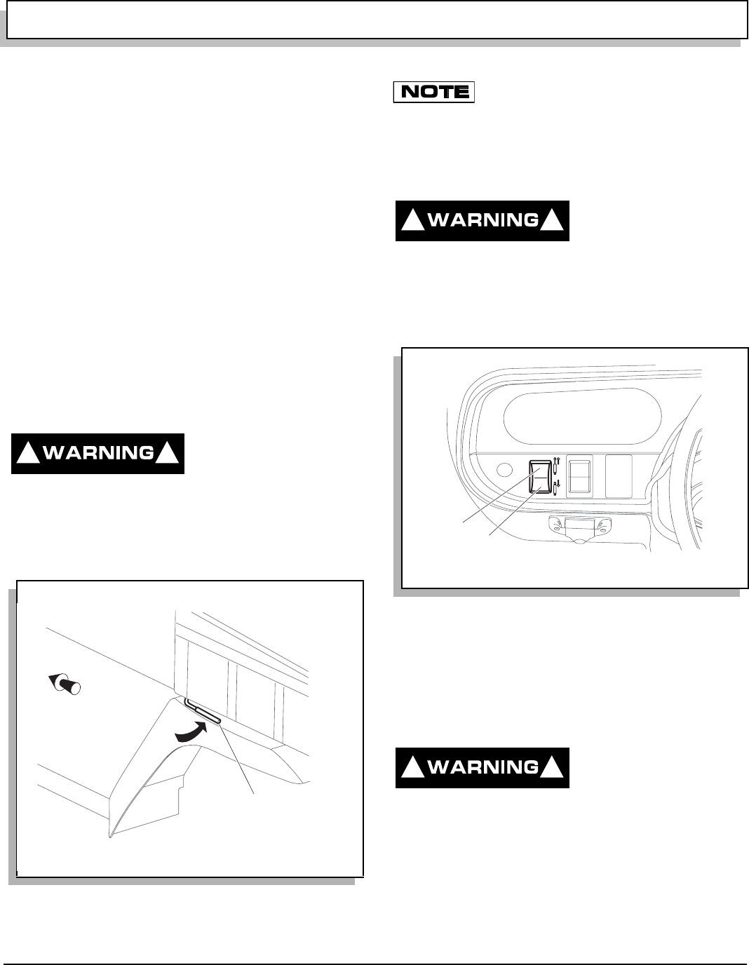
MANUAL LIFT BED
To reduce possibility of
severe injury, exercise
caution while manually
lifting or lowering load bed. Fingers or other body
parts could be trapped under falling bed.
To raise manual lift bed, locate latch handle at front left
side of bed, pull handle up with one hand to release and
lift bed with other hand (Ref. Fig. 14 on page 9).
A gas strut located underneath will assist in raising bed
when empty and will keep it raised when empty.
Over time, the gas strut may allow the truck
bed to slowly lower. If this condition is evident,
replacement of gas strut is required.
To lower manual lift bed, push down on bed until latch
catches. Be sure hands are not trapped by load bed.
ELECTRIC LIFT BED OPERATION
To reduce possibility of
severe injury, exercise
caution while lifting or
lowering load bed. Fingers or other body parts could
be trapped under bed.
The electric lift toggle switch is located at left side of dash
panel (Ref. Fig. 15 on page 9). Push top part of switch to
raise load bed and bottom part to lower.
WINCH
An optional winch is available. Read, understand and fol-
low all following information on operation and use of
winch before attempting to operate it.
WINCH APPLICATIONS
To reduce possibility of
severe injury or death,
the following must be
observed:
Have all persons and pets leave area while operat-
ing winch. Never allow anyone to remain in vehi-
cle.
Make sure object to which cable is attached can-
not be damaged or pulled over onto vehicle and
it’s occupants. If attaching winch to a dead tree, a
section or limb could fall.
Fig. 14 Manual Lift Bed Release
! !
Front of Vehicle
Manual Load Bed
Latch Handle
Pull Up To Release
And Lift Bed
Ref Mbl 4
Fig. 15 Electric Lift Bed Switch
! !
Ref Lbs 2
Up
Down
! !
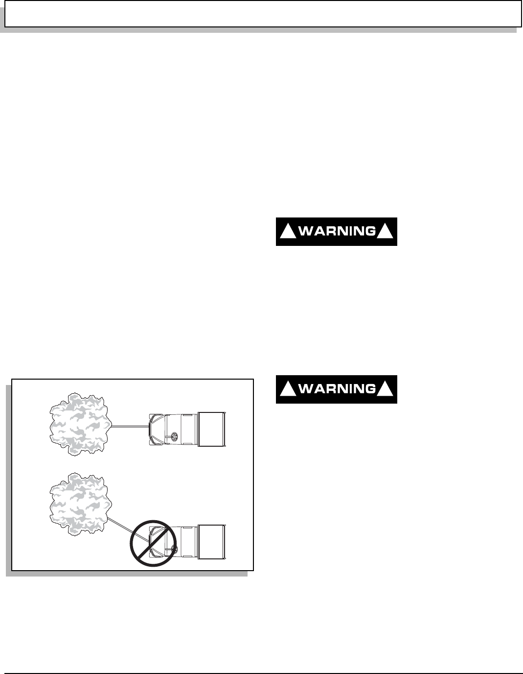
OPERATION AND SERVICE INFORMATION
Page 10 Owner’s Manual and Service Guide
Read all of manual to become thoroughly familiar with this vehicle. Pay particular attention to all Notes, Cautions and Warnings
Do not pull at an angle (Ref. Fig. 16 on page 10).
This will cause cable to pile up on one end, jam-
ming and damaging winch. The winch cable could
also break from being overstressed and strike
someone. Pulling vehicle at an angle can cause
damage to front suspension and may cause vehi-
cle to overturn. When pulling vehicle, pull straight
only.
If vehicle is being used as an anchor to winch a
load, it should have park brake set and wheels
chocked.
Never use winch to lift people or other overhead
loads. The winch is not intended to be used in any
hoisting operation.
Do not use winch to secure loads. Use a tie down
designed for the job.
Do not apply shock loads to winch.
Do not attempt to modify or weld winch.
Rolling load capacity of winch decreases with
steepness of slope.
Winch is designed for intermittent duty only. The
electric motor should not be allowed to become
excessively hot. If motor becomes uncomfortably
hot to touch, stop and allow motor to cool.
Winch may be used for a number of purposes, including
pulling vehicle if it loses traction on unsuitable terrain or
becomes stuck or ‘hung up’ on an obstruction.
It is impossible to predict all conditions a winch could be
used; therefore, the following warnings should not be
considered as complete. Before operating winch, con-
sider possible dangers and take precautions to protect
yourself, your passenger and any bystanders.
When pulling vehicle with winch, pull straight only. Do
not permit cable to contact side of drum.
WINCH MOUNTING
Winch can be mounted at front, or rear (if vehicle is
equipped with optional rear hitch) of vehicle to accommo-
date different situations. At front, winch is mounted in
receiver of frame below cowl (Ref. Fig. 17 on page 11).
At rear, winch is mounted in hitch receiver below load
bed.
Unplug winch remote
control before working
on winch drum in order
to prevent inadvertent operation.
Before moving winch, unplug winch connector from wire
harness. To move winch from one end of vehicle to other,
remove spring pin, pull out clevis pin and pull winch
mount tube out of receiver. Move to opposite end of vehi-
cle and install winch mount tube in receiver. Secure by
inserting clevis pin and securing with spring pin. Plug
winch connector into wire harness.
WINCH OPERATION
To reduce possibility of
severe injury or death,
the following warnings
must be observed before attempting to operate
winch:
Always wear thick leather gloves when handling
wire cable.
Replace frayed wire cable with a direct factory
replacement only.
Never operate winch with less than five (5) full
turns of cable around drum (Ref. Fig. 19 on page
12).
If winch motor stalls from overloading, do not
continue applying power to winch. The wire cable
may become overstressed.
Do not attempt to pull loads exceeding 1500 lbs.
(680 kg).
To pull out cable, free spool clutch knob must be
used. Pull out and rotate knob. If cable is under
any load, clutch may not release easily. Jog out
some cable to release tension and operate clutch.
Fig. 16 Do Not Pull at Angle
Correct
Incorrect
Ref Wps 2
! !
! !
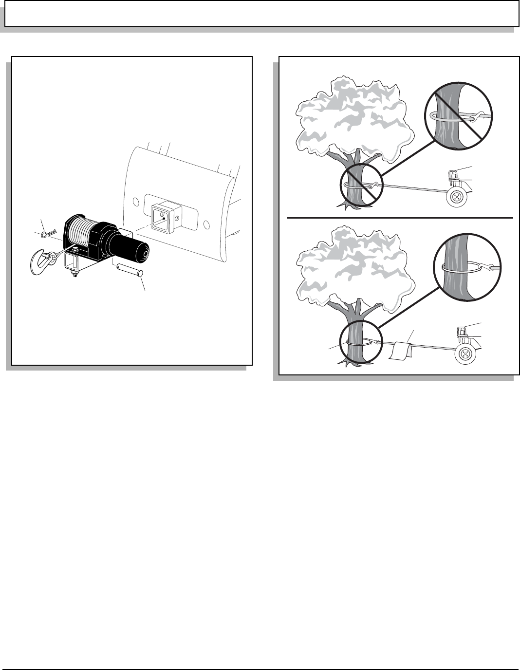
OPERATION AND SERVICE INFORMATION
Page 11
Owner’s Manual and Service Guide
Read all of manual to become thoroughly familiar with this vehicle. Pay particular attention to all Notes, Cautions and Warnings
Pull out desired amount of cable and secure.
Engage drum by rotating knob until it snaps in
place. Never operate winch unless clutch is
engaged.
To prevent damage to wire cable, never hook
cable to itself. Always use a nylon sling (Ref. Fig.
18 on page 11).
Stay clear of winch, cable and cable hook. Place a
heavy cloth, jacket or blanket over cable to act as
a damper should cable break when operating
winch (Ref. Fig. 18 on page 11).
Remember that winch operation with engine off
will drain battery and may leave insufficient power
to start vehicle. Always let engine idle while using
winch.
When operating winch, keep entire area in view.
Never release free spool clutch while cable is
under load.
Never work around winch drum or cable under
tension.
Unplug winch remote control before working on
winch drum in order to prevent inadvertent opera-
tion.
Take up slack in cable slowly. Stop winch before
cable becomes tight and inspect all attachments
such as winch attachment, hook attachment,
nylon sling (if required) and load attachment.
Plug winch remote control into receptacle located on
dash panel (Ref. Fig. 19 on page 12).
To unwind cable, locate clutch knob on winch (Ref. Fig.
19 on page 12). Pull out knob and rotate 90° to lock out.
Using handsaver bar, pull cable from winch drum. Leave
at least five turns of cable on drum. Engage drum by
turning clutch knob 90°, returning it to original position.
To wind cable, use handsaver bar to keep tension on
cable while activating remote. When winding cable,
make sure it winds tightly and evenly onto drum leaving
no gaps that could cause premature wear to cable. When
using winch under a load, operate remote control as far
Fig. 17 Mounting Winch
Clevis
Pin
Spring
Pin
Winch shown mounted at front of vehicle
Ref Wmt 2
Fig. 18 Use Nylon Sling and Install a Damper when
Winching
Ref Wca 3
Nylon
Sling
Damper
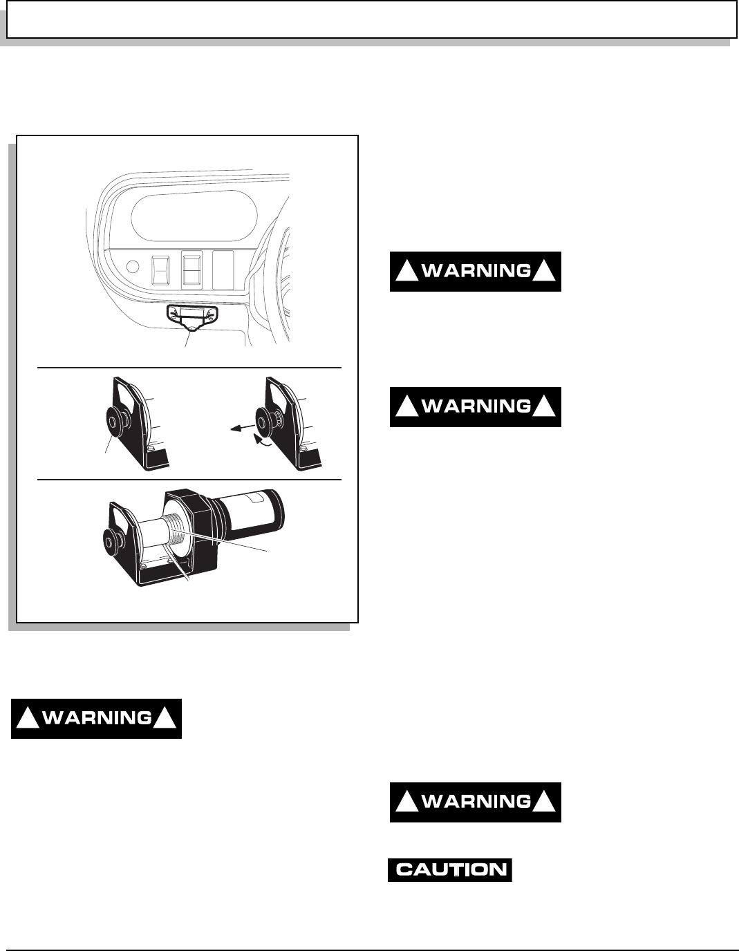
OPERATION AND SERVICE INFORMATION
Page 12 Owner’s Manual and Service Guide
Read all of manual to become thoroughly familiar with this vehicle. Pay particular attention to all Notes, Cautions and Warnings
as possible from side of vehicle. Do not operate winch
while sitting in passenger seat. Read ‘Winch Applica-
tions’ section before attempting to operate winch.
TOP AND WINDSHIELD
The sun top does not
provide protection from
falling objects.
The windshield does not provide protection from tree
limbs or flying objects.
Sun top and windshield can only be used with ROPS
(Roll Over Protection System) equipped vehicles.
Sun top and windshield provide some protection from the
elements; however, they will not keep operator and pas-
senger dry in a downpour. An optional Cab provides pro-
tection from the weather, utilizes an optional windshield
wiper which is also available with the windshield
equipped ROPS unit.
The sun top has been designed to provide roll over pro-
tection and requires the ROPS system to be installed. In
addition, the sun top does not protect against falling
objects nor does the windshield protect against flying
objects and tree limbs. Keep arms and legs inside of
vehicle while it is moving.
TRANSPORTING VEHICLE
TOWING
This vehicle is not
designed to be towed.
It is recommended that
vehicle be moved by placing entire vehicle on a trailer,
flatbed truck or other suitable transport.
HAULING
To reduce possibility of
severe injury or death
while transporting vehi-
cle:Secure vehicle and contents.
Never ride on vehicle being transported.
Always remove windshield before transporting.
Maximum speed with sun top installed is 50 mph
(80 kph).
If vehicle is to be transported at highway speeds, the sun
top must be removed. When transporting vehicle below
highway speeds, check for tightness of hardware and
cracks in sun top at mounting points. It is recommended
that the windshield be removed when transporting.
Always verify vehicle and contents are adequately
secured before transporting. Rated capacity of trailer or
truck must exceed weight of vehicle (see GENERAL
SPECIFICATIONS for vehicle weight) and load. Lock
park brake and secure vehicle using ratchet tie downs.
TOWING A TRAILER
To reduce possibility of
severe injury or death,
trailer weight is never to
exceed 1500 lbs. (680 kg).
To reduce possibility of vehicle dam-
age, do not exceed 1500 lbs. (680 kg)
trailer weight nor 150 lbs. (68 kg) tongue weight.
Fig. 19 Winch Operation
Winch Remote Plug
Ref Wop 1
Pull Out
ENGAGED
Clutch Knob
LOCKED
OUT
Turn 90˚
Minimum of 5 Turns
Of Cable On Drum
! !
! !
! !
! !
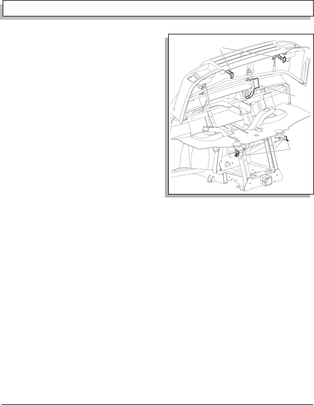
OPERATION AND SERVICE INFORMATION
Page 13
Owner’s Manual and Service Guide
Read all of manual to become thoroughly familiar with this vehicle. Pay particular attention to all Notes, Cautions and Warnings
Vehicle may be equipped with a receiver that accepts a
standard 2" ball hitch. Trailer range of motion is limited by
the ball and hitch and should not be used on rough trails
or over objects such as logs, large rocks, holes, etc.
Never install non-factory baskets or extensions in hitch
receivers (front or rear). Such items change performance
characteristics of vehicle and result in unsafe handling,
possible roll over or vehicle damage.
Remember a loaded trailer always reduces overall
capacity of vehicle.
At no time should tongue weight be more than 150 lbs
(68 kg).
The maximum weight that can be towed on a trailer is
1500 lbs. (680 kg).
OPENING THE COWL (HOOD)
To lift cowl (Ref. Fig. 20 on page 13):
•Pull down and out on both latches to clear receiv-
ers mounted to frame
•Lift cowl up fully to allow catch to rest on cross-
member and release cowl
To lower cowl:
•Lift cowl up fully with one hand to remove weight
from catch
•Pull catch away from crossmember with other
hand
•Lower cowl until catch clears crossmember and
continue lowering cowl with both hands
•Once seated on rubber bumpers, secure with
latches
DATA LABEL LOCATION
Serial number label is located on body just below air
intake louvers near choke knob.
Manufacture date code and repeat of serial number are
on data labels located on frame crossmember under bed.
See LOAD BED on page 8.
Design changes take place on an ongoing basis. In order
to obtain correct components for vehicle, manufacture
date code, serial number and vehicle model must be pro-
vided when ordering service parts.
Fig. 20 Unlatching Cowl
Ref Lco 1
Latches
Catch
Latch
Receiver
OPERATION AND SERVICE INFORMATION
Page 14 Owner’s Manual and Service Guide
Read all of manual to become thoroughly familiar with this vehicle. Pay particular attention to all Notes, Cautions and Warnings
MAINTENANCE
To reduce possibility of
severe injury or death
from improper servicing
techniques:
Do not attempt any type of servicing operations
before reading and understanding all notes, cau-
tions and warnings in this manual.
Wear eye protection when working on
vehicle. Use extra care when working
around batteries, or using solvents or
compressed air.
Turn off all electrical loads from battery before
removing battery wires.
Wrap wrenches with vinyl
tape to reduce possibility of a
dropped wrench ‘shorting
out’ a battery, which could result in an explosion.
Remove and ground spark plug wires and discon-
nect battery at negative terminal before servicing.
Treat all electrolyte spills to body and eyes with
extended flushing with clear water. Contact a phy-
sician immediately. Any electrolyte spills should
be neutralized with a solution of 2 teaspoons (10
ml) sodium bicarbonate (baking soda) dissolved
in 1 quart (1 liters) of water and flushed with
water.
Insulate metal aerosol containers of battery termi-
nal protectant to reduce chance of contacting bat-
tery terminals which could result in an explosion.
Always place entire vehicle on jack stands, disen-
gage four (4) wheel drive and unlock front and
rear differentials when performing a procedure
requiring engine to run with vehicle in place and
tires off ground. Failure to do so will allow vehicle
to pull itself off when supported by only two jack
stands.
It is in the best interest of both vehicle owner and service
technician to carefully follow procedures recommended
in this manual. Preventative maintenance, applied at rec-
ommended intervals, is the best guarantee for keeping
vehicle both dependable and economical.
This vehicle will give years of satisfactory service, provid-
ing it receives regular maintenance. For appropriate ser-
vice intervals: See PERIODIC SERVICE SCHEDULE on
page 15. For appropriate locations See ‘LUBRICATION
POINTS’ on page 21.
To prolong vehicle life, some mainte-
nance items must be serviced more fre-
quently on vehicles used under severe driving conditions such
as extreme temperatures, extreme dust/debris conditions, fre-
quent use with maximum load.
To reduce possibility of vehicle damage when servicing:
•Do not lift vehicle by placing jack under front or
rear aluminum differential cases: See ‘Lifting the
Vehicle’ on page 17.
•Always place entire vehicle on jack stands, select
two (2) wheel drive and unlock both differentials
when performing procedures requiring engine to
run with vehicle in place and tires off ground. Fail-
ure to do so will allow vehicle to pull itself off when
supported by only two jack stands.
•Do not operate engine with CVT drive belt
removed since engine speed is governed by the
transfer case. Doing so allows engine to exceed
its maximum revolutions per minute (RPM).
To access powertrain for routine maintenance, lift seat.
Additional access may be obtained by raising or remov-
ing load bed. For major repair, refer to appropriate Tech-
nician’s Repair and Service Manual.
Some service procedures may require vehicle to be
lifted. For proper lifting procedure and safety information:
See ‘LIFTING THE VEHICLE’ on page 17.
! !

OPERATION AND SERVICE INFORMATION
Page 15
Owner’s Manual and Service Guide
Read all of manual to become thoroughly familiar with this vehicle. Pay particular attention to all Notes, Cautions and Warnings
PERIODIC SERVICE SCHEDULE
ITEM
BEFORE
EACH
USE WEEKLY
EVERY
20
HOURS
EVERY
50
HOURS
EVERY
100
HOURS
EVERY
200
HOURS
EVERY
300
HOURS
EVERY
500
HOURS
Service Brake
(Pedal Pressure) Check X
(Fluid Level) Check X
(Pads & Shoes) Inspect X
(Rotors & Drums) Clean X
Park Brake Clean X X
Tires Check X X
Overall Vehicle Condition Check X
Wheels Check X
Fuel Gauge Check X
Alternator Belt Check X
Engine Fan and Cooling Fins Clean X
CVT Enclosure
(Blockage) Clean X
(Damage) Repair/
Replace X
Wiring Check X
Accelerator Check X
Choke Check X
Carburetor Linkage Check X
Direction Selector Check X
Engine Oil Check X
Change X ** X
Engine Oil Filter Replace X ** X
Air Filter Check X
Clean X#
Replace X#
Spark Plugs Check X
Replace X
Idle Speed Check X**
Valve Clearance Check X** X
Fuel Filter Check X
Replace X
Combustion Chamber Clean X
Steering Check X
Fig. 21 Periodic Service Schedule
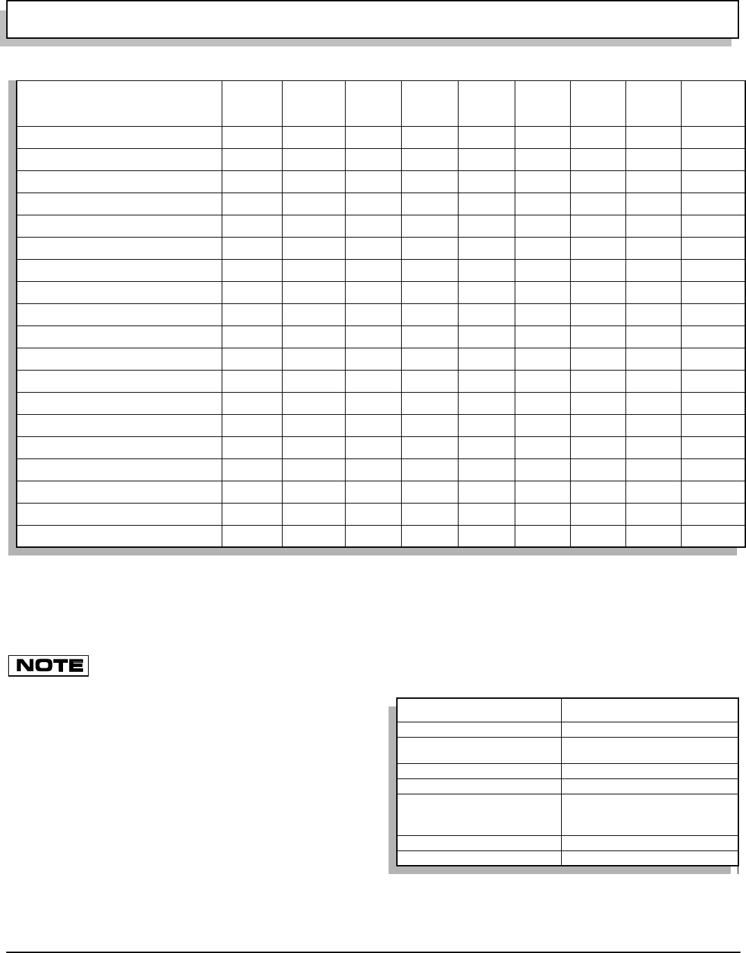
OPERATION AND SERVICE INFORMATION
Page 16 Owner’s Manual and Service Guide
Read all of manual to become thoroughly familiar with this vehicle. Pay particular attention to all Notes, Cautions and Warnings
** First occurrence only # More frequently in dusty conditions
To perform service that is listed in this schedule but not described in this manual, contact a local Service Representative
or see Repair and Service Manual for this vehicle.
Some maintenance items must be serviced more frequently on vehicles used under severe driving conditions.
BASIC SERVICE PARTS
To order parts, SERVICE PARTS Department contact
information is as follows:
In USA, Phone: 1-800-241-5855; Fax: 1-800-448-8124
Outside USA, Phone: 010-1-706-798-4311; Fax: 010-1-
706-771-4609
E-Z-GO Division of TEXTRON, Inc., 1451 Marvin Griffin
Road, Augusta, Georgia USA 30906-3852
ITEM
BEFORE
EACH
USE WEEKLY
EVERY
20
HOURS
EVERY
50
HOURS
EVERY
100
HOURS
EVERY
200
HOURS
EVERY
300
HOURS
EVERY
500
HOURS
Tie Rods/Linkages Check X
Rear Axle Check X** X
Replace X
Muffler/Exhaust Check X
Spark Arrester Clean X
Front Axle Check X** X
Front Knuckles Check X
Front Struts Check X
Front Wheel Alignment Check X
Rear Shock Absorbers Check X
Fuel Tank Clean X
Throttle/Governor Linkage Check X
Hardware And Fasteners Check X
Tighten X
Battery Clean X
Drive Belt Check X
Front Wheel Bearings Check X
Drive shafts Lubricate X
C.V.Joints and Boots Check X
Fig. 21 Periodic Service Schedule
Air Filter Element 72944-G01
Oil Filter 15400-POH-305PE
Spark Plugs ZGR5A (NGK)
J16CR-U (DENSO)
Optional Alternator Belt 73561-G01
CVT Belt 73965-G01
Fuse 15 amp (P/N 35212-G01)
20 amp (P/N 35212-G02)
7.5 amp (P/N 35212-G05)
Headlight Bulb 20209-G3
Tail Light Bulb #1157 (P/N 21759-G1)
Fig. 22 Basic Service Parts
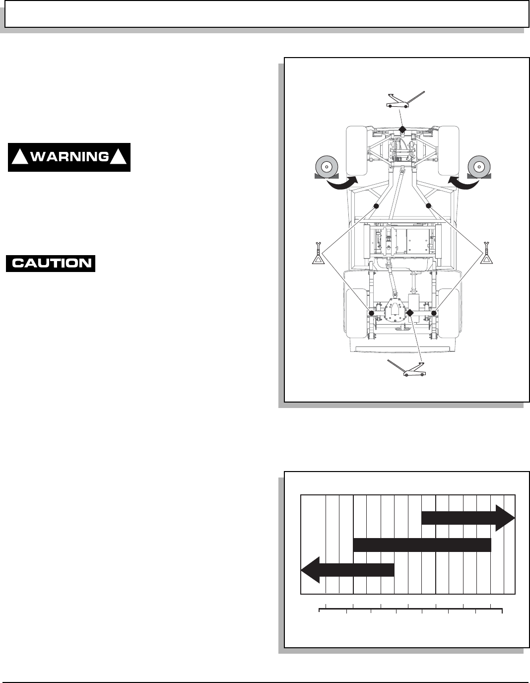
OPERATION AND SERVICE INFORMATION
Page 17
Owner’s Manual and Service Guide
Read all of manual to become thoroughly familiar with this vehicle. Pay particular attention to all Notes, Cautions and Warnings
LIFTING THE VEHICLE
Tool List Qty. Required
Floor jack .................................................................... 1
Jack stands ................................................................. 4
Chocks ........................................................................ 4
To prevent possible inju-
ry or death resulting
from vehicle falling off
jack, be sure vehicle is on a firm and level surface.
Never get under vehicle while it is supported by a
jack. Use jack stands and test vehicle stability on
stands. Always place chocks in front and behind the
wheels not being raised. Use extreme care since vehi-
cle is extremely unstable during lifting process.
To prevent possible injury or
death from operating engine
while vehicle is raised, disengage 4 wheel drive and
unlock front and rear differentials. To reduce possibil-
ity of vehicle damage:
Do not raise vehicle by placing jack under front or rear aluminum
differential cases.
Do not operate engine with 4 wheel drive or either differential
locks engaged.
Never operate engine with CVT drive belt removed.
Some servicing operations may require entire vehicle to
be raised (Ref. Fig. 23 on page 17).
Install chocks in front and behind each front wheel. Cen-
ter jack under flange on long axle tube. Raise vehicle and
locate a jack stand under outer ends of rear axle tubes.
Lower jack and test stability of vehicle on two jack
stands.
Center jack under front of frame. Raise vehicle and posi-
tion jack stands under frame as shown.
Lower jack and test stability of vehicle on four jack
stands.
Lower vehicle by reversing lifting sequence.
OIL
Use detergent motor oil designed for 4 stroke engines.
The oil must be of high quality and meet API SF, SG
standards.
For most conditions, 10W30 oil is recommended (Ref.
Fig. 24 on page 17).
See chart for viscosity allowed in extreme temperatures
(Ref. Fig. 24 on page 17).
! !
Fig. 23 Lifting the Vehicle
Fig. 24 Recommended Oil
Ref Liv 5 View From Underside of Vehicle
-20 0 20 40 60 80 100
-30 -20 -10 0 10 20 30 40
C
F 0
30
30
(Air Temperature)
10W-30
10W-30
5W-30
5W-30
0
Ref Ovc 3
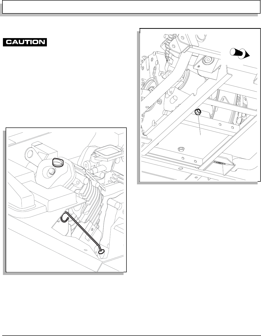
OPERATION AND SERVICE INFORMATION
Page 18 Owner’s Manual and Service Guide
Read all of manual to become thoroughly familiar with this vehicle. Pay particular attention to all Notes, Cautions and Warnings
OIL LEVEL CHECK
To reduce possibility of engine damage,
do not run engine with oil level too low.
Park vehicle on level surface, shut off engine and wait a
minute for oil to settle.
Lift seat, remove dipstick and wipe clean (Ref. Fig. 25 on
page 18).
Replace dipstick and remove again. Observe level indi-
cated and:
if it is between upper and lower holes, oil level is correct
if it is at or below the lower hole, remove oil fill cap and
add oil until level reaches upper hole
When finished, return dipstick and oil fill cap and lower
seat.
OIL CHANGE
With engine warm, park vehicle on level surface, shut off
engine, remove key, set park brake and wait a minute for
oil to settle.
Lift seat, wipe oil fill cap clean with a cloth and remove fill
cap (Ref. Fig. 25 on page 18).
Place drain pan under engine.
Remove drain plug from base of engine (Ref. Fig. 26 on
page 18).
Once oil has drained, replace drain plug and, if due,
change oil filter at this time (Ref. OIL CHANGE on page
18).
Fill engine to upper hole on dipstick with appropriate oil
(Ref. Fig. 24 on page 17).
Return oil fill cap and dipstick and lower seat.
OIL FILTER CHANGE
Drain oil (Ref. OIL CHANGE on page 18).
Clean oil filter and its mount (Ref. Fig. 27 on page 19).
Place drain pan under engine and, being careful not to
damage oil pressure switch, remove oil filter.
Wipe sealing surface of filter mount clean.
Apply clean, fresh oil to seal of new filter and screw filter
on by hand until seal contacts filter mount. Tighten 7/8 of
a turn more. Torque specification is 16 ft. lbs. (22 Nm).
Fig. 25 Oil Fill and Level Check
Ref Olc 1
Oil Fill Cap
Dip Stick
Fig. 26 Oil Change
Ref Odp 1
Front of Vehicle
Drain
Plug
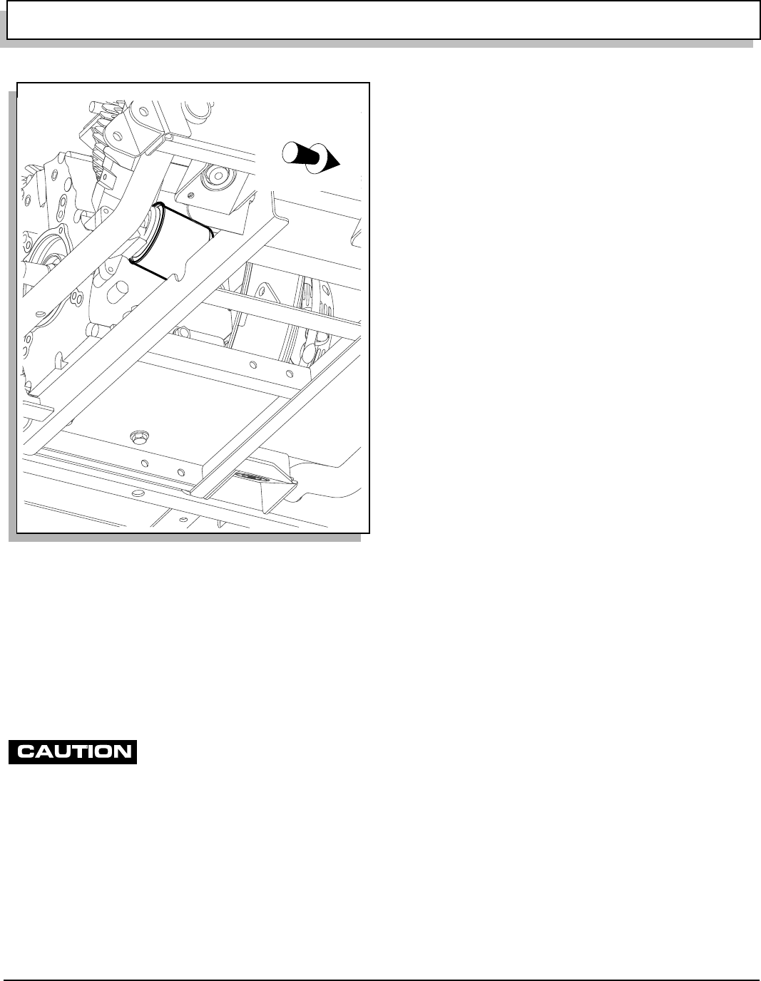
OPERATION AND SERVICE INFORMATION
Page 19
Owner’s Manual and Service Guide
Read all of manual to become thoroughly familiar with this vehicle. Pay particular attention to all Notes, Cautions and Warnings
Fill engine to upper hole on dipstick with appropriate oil
(Ref. OIL CHANGE on page 18).
Return oil fill cap and dipstick and lower seat.
Start engine and check for leaks.
Shut engine off, check oil level and add, if necessary, to
bring level to upper hole on dipstick.
SPARK PLUGS
To reduce possibility of engine damage:
Only use recommended spark plugs.
Tighten spark plugs as instructed. Too loose can overheat
engine and too tight can damage threads in cylinder head.
Inspect and replace spark plugs at intervals indicated in
Periodic Service Schedule. See ‘PERIODIC SERVICE
SCHEDULE’ on page 15.
Remove plug wires and clean area around plugs to pre-
vent debris falling into cylinders. Use a 13/16” spark plug
wrench to remove plugs.
Inspect electrodes for wear and insulator for cracks or
chips. Fouled spark plugs are indicated by a wet, black
appearance. This could be caused by a dirty air filter ele-
ment or other restrictions in air intake system. Incorrectly
adjusted valves, spark plug wires which are in poor con-
dition or poor quality fuel could also contribute.
If reusing spark plugs, clean with wire brush.
Check gap. Gap should measure .028 - .031" (.70 - .80
mm). If necessary, adjust gap being careful not to dam-
age plug.
If replacing spark plugs, use only recommended type.
(Ref. Fig. 22 on page 16). New plugs must be properly
gapped before installation.
Install plugs by hand to reduce chance of cross-thread-
ing.•When plug seats against engine:
•Tighten used plugs an additional 1/8 to 1/4 turn.
•Tighten new plugs an additional 1/2 turn.
ALTERNATOR BELT
Vehicle may be equipped with an optional hi-output alter-
nator (Ref. Fig. 28 on page 20). It provides power neces-
sary to run a variety of equipment such as electric
powered tools, hi-intensity lighting, radio and winch.
ADJUSTING BELT
Hardware involved: 1/2" and 9/16" hex
Special Tools Required Qty.
Torque wrench, ft. lbs. ................................................. 1
Belt tension gauge....................................................... 1
Inspect belt for cracking or wear. Replace if required.
Loosen top nut.
Loosen bottom bolt.
By hand or using a pry bar, pull alternator belt tight and
hand tighten bottom bolt.
Check belt tension. Tighten to (Ref. Fig. 28 on page 20):
75 - 80 lbs. (34 - 36 kg) tension for an existing belt or 90
- 110 lbs. (41 - 50 kg) tension for a new belt when using a
belt tension gauge. Apply gauge half way between the
two pulleys.
-or-
a maximum deflection of 1/2" (13 mm) for an existing
belt or 3/8" (1 cm) for a new belt when gauging by hand.
Tighten bolt to 9 - 11 ft. lbs. (12 - 15 Nm) torque and nut
to 18 - 20 ft. lbs. (25 - 27 Nm).
Fig. 27 Oil Filter Change
Ref Ofi 1
Front of Vehicle
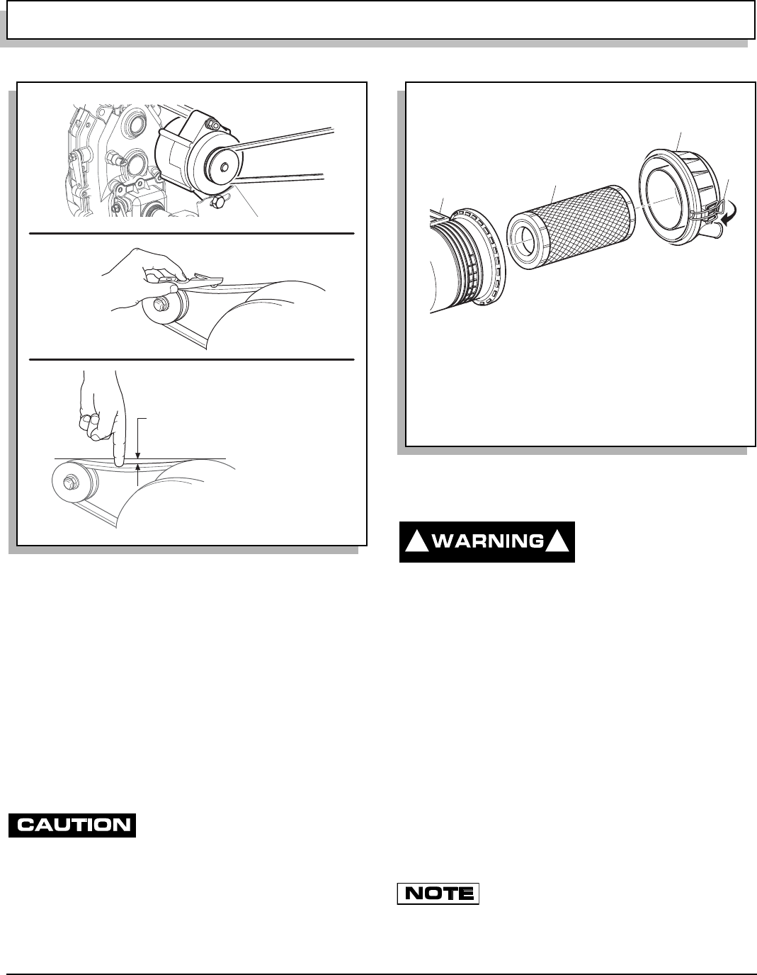
OPERATION AND SERVICE INFORMATION
Page 20 Owner’s Manual and Service Guide
Read all of manual to become thoroughly familiar with this vehicle. Pay particular attention to all Notes, Cautions and Warnings
AIR CLEANER
CANISTER TYPE AIR CLEANER
Air cleaner element is accessible by unsnapping two
clips on air canister and removing cover and air filter ele-
ment (Ref. Fig. 29 on page 20).
Clean inside of cover and canister.
Install element and cover the same way they were
removed. Be sure positioning arrow on cover is pointing
up and all clips are fastened securely.
CLEANING AIR FILTER ELEMENT
Do not use compressed air to clean air
filter; doing so will damage filter which
may result in damage to engine.
If element is in acceptable condition, loose dirt may be
removed by tapping filter lightly. Do not use oil on filter
element or any part of unit.
FUEL FILTER
To reduce possibility of
an explosion, do not
smoke near fuel tank or
in an area where gasoline is being handled. Do not
perform procedures involving fuel system near open
fire or electrical items which could produce a spark.
Do not handle gasoline in an area that is not ade-
quately ventilated.
Always wear safety glasses to prevent possible eye
injury from gasoline or gasoline vapor.
Fuel filter is located at front of engine above fan cover
(Ref. Fig. 30 on page 21).
Inspect it for dirt and/or water. Replace if significant
amount is found.
To replace, use a pair of pliers to move clamps off ends
of filter.
Remove hose coming from fuel tank first and plug.
Remove filter from hose going to fuel pump and discard.
Orient direction of new fuel filter according to
FLOW arrow on side of filter.
Install new fuel filter and reposition clamps over inlet and
outlet.
Fig. 28 Adjusting Alternator Belt
Ref Abt 3
3/8" (1 cm) Max. Deflection for New Bel
t
1/2" (1.3 cm) Max. Deflection for Existing
Belt
Fig. 29 Air Cleaner
Air Cleaner
Cover
Air Cleaner
Canister
Air Filter
Element
R
ef Air 4
Clip
! !
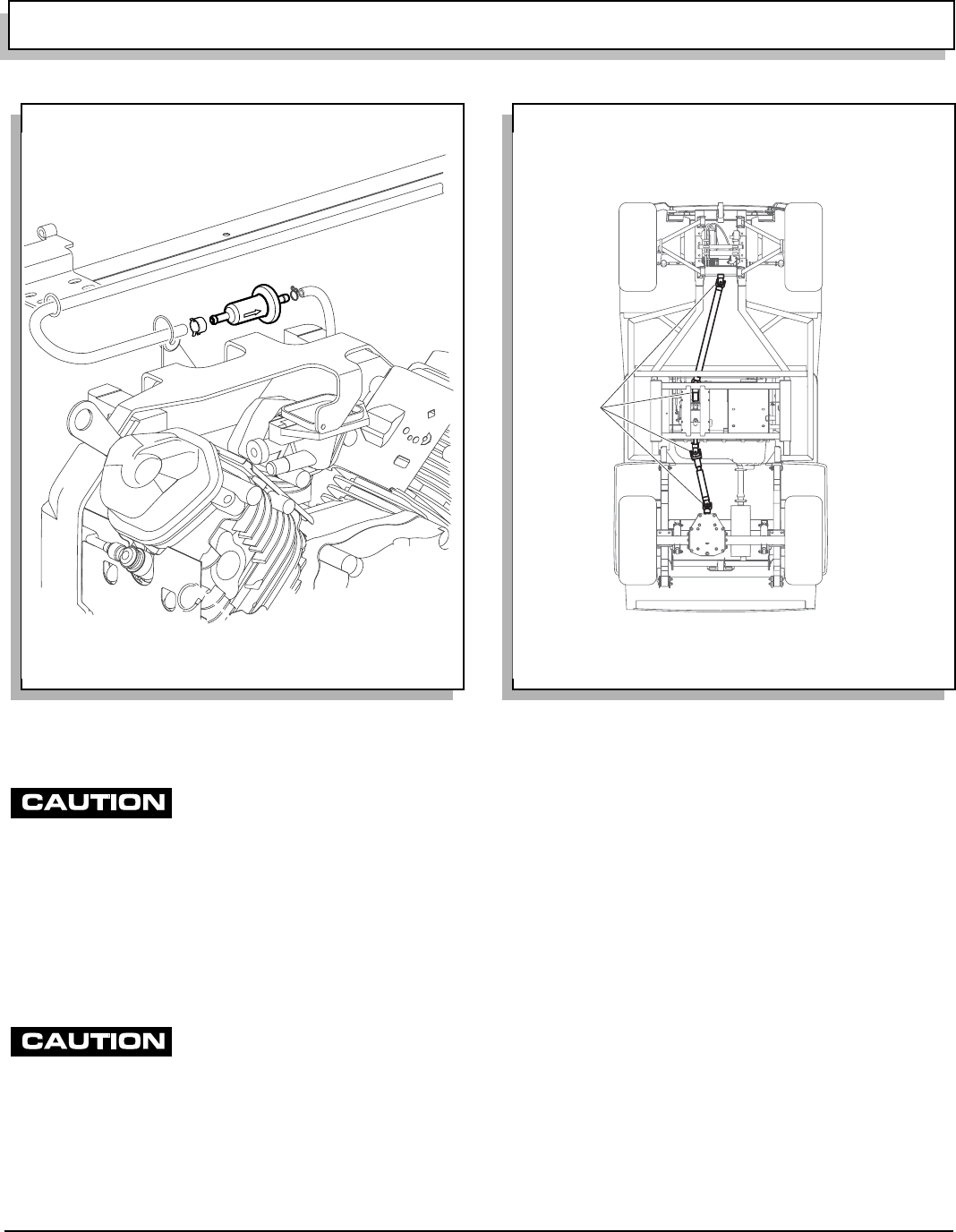
OPERATION AND SERVICE INFORMATION
Page 21
Owner’s Manual and Service Guide
Read all of manual to become thoroughly familiar with this vehicle. Pay particular attention to all Notes, Cautions and Warnings
LUBRICATION POINTS
Do not use more than three (3) pumps
of grease in any grease fitting at any
one time. Excess grease may cause grease seals to fail or
grease migration into areas that could damage components.
Add no more than two or three pumps of grease to fit-
tings shown (Ref. Fig. 31 on page 21). More than three
pumps in a grease fitting could damage seals allowing
contamination of grease-sensitive components.
BATTERY
To reduce possibility of discharging
battery and leaving insufficient reserve
to start vehicle, do not use accessories excessively while engine
is off.
Failure to promptly charge a discharged battery will shorten its
life span.
Unless equipped with optional high output alternator, the
vehicle uses a charge coil to charge battery. Battery is
charged while engine is running. Do not operate acces-
sory items (such as accessory lights, radios, winch, etc.)
excessively while engine is off. The charge coil is capa-
ble of supplying 20 amps; therefore, operation of all
accessories could result in discharge of battery even
though engine is running.
Discharging and recharging a battery is known as deep
cycling. The battery is not a deep cycle model, but is a
starting battery that is intended to maintain a full charge
from the charging circuit. Multiple deep cycles will result
in premature failure of battery.
If battery becomes discharged, vehicle can be jump
started. See JUMP STARTING on page 22. After starting,
promptly charge battery using a 12 volt charger rated at
10 amps or less and in accordance with all instructions
provided by the manufacturer of charger.
Fig. 30 Fuel Filter
Ref Ffi 1
Fig. 31 Lubrication Points
Ref Lub 5
Slip Joints
& U-Joint
Yokes
View From Underside of Vehicle
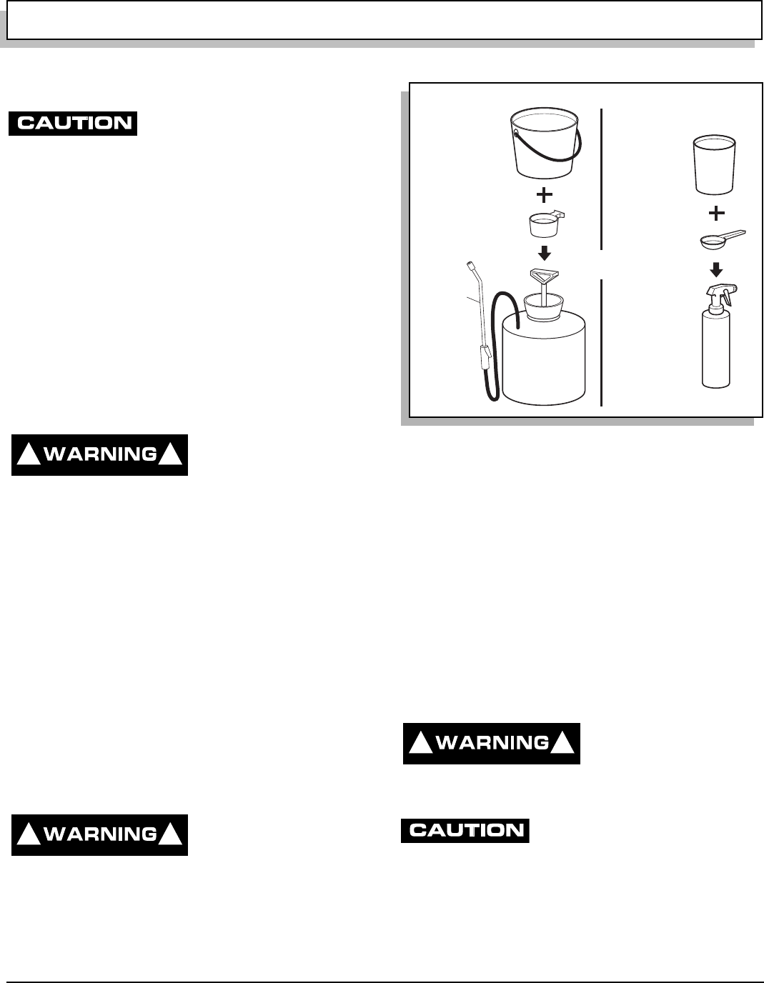
OPERATION AND SERVICE INFORMATION
Page 22 Owner’s Manual and Service Guide
Read all of manual to become thoroughly familiar with this vehicle. Pay particular attention to all Notes, Cautions and Warnings
BATTERY CLEANING
To reduce possibility of damage to
vehicle or floor, neutralize acid before
rinsing battery.
To reduce possibility of damage to electrical components while
cleaning, do not use a pressure washer.
Cleaning should take place per PERIODIC SERVICE
SCHEDULE See ‘PERIODIC SERVICE SCHEDULE’ on
page 15.
When cleaning outside of battery and terminals, first
spray with a solution of sodium bicarbonate (baking
soda) and water to neutralize any acid deposits before
rinsing with clear water.
Use of a water hose without first neutralizing any acid,
will move acid from top of battery to other parts of vehicle
or storage facility where it will attack metal, concrete or
asphalt. Additionally, a conductive residue will remain on
battery and will contribute to its discharge.
To reduce possibility of
battery explosion that
could result in severe
injury or death, do not use metallic spray wand to
clean battery and keep all smoking materials, open
flame or sparks away from battery.
Correct cleaning technique is to spray top and sides of
battery with solution of sodium bicarbonate (baking soda)
and clear water (Ref. Fig. 32 on page 22). Solution
should consist of amounts shown in diagram and is best
applied with a garden type sprayer equipped with a non
metallic spray wand or a plastic spray bottle. In addi-
tion, special attention should be paid to metal compo-
nents adjacent to battery which should also be sprayed
with solution. Allow solution to sit for at least three min-
utes. Use a soft bristle brush or cloth to wipe battery;
removing any residue that could contribute to self dis-
charge of battery. Rinse entire area with clean water. Do
not use a pressure washer.
JUMP STARTING
To reduce possibility of
severe injury or death,
follow jump starting
instructions explicitly.
To reduce possibility of permanent damage to battery, promptly
charge a discharged battery.
Turn key switch to OFF.
Place direction selector in neutral.
Attach one end of red positive cable to positive post of
weak battery and other end to positive post of strong bat-
tery (Ref. Fig. 33 on page 23).
Attach one end of black negative cable to negative post
of strong battery and other end to vehicle frame.
Start vehicle as usual. Once started, disconnect cables in
reverse order.
Charge battery as soon as possible (Ref. BATTERY on
page 21).
VEHICLE CLEANING AND CARE
CLEANING
To reduce possibility of
severe injury or vehicle
damage, read and under-
stand all instructions supplied by manufacturer of
pressure washer.
To reduce possibility of damage, do not
use pressure in excess of 700 psi (4826
kPa) when pressure washing exterior of vehicle and do not use
any abrasive or reactive solvents to clean plastic parts.
It is important that proper techniques and cleaning mate-
rials be used. Using excessive water pressure may
cause severe injury to operator or bystander, damage to
seals, plastics, seat material, body finish or electrical sys-
! !
! !
Fig. 32 Cleaning Battery
1 1/2 gallons
(6 liters)
Clear Water
1/4 Cup (60 ml)
Sodium Bicarbonate
(Baking Soda)
2 Gallon
(7.5 liter)
Garden
Sprayer
R
ef Pns 1
1 quart
(1 liter)
Clear Water
2 Teaspoons
(10 ml)
Sodium
Bicarbonate
(Baking Soda)
Plastic
Spray
Bottle
OR
Non
Metallic
Wand
! !
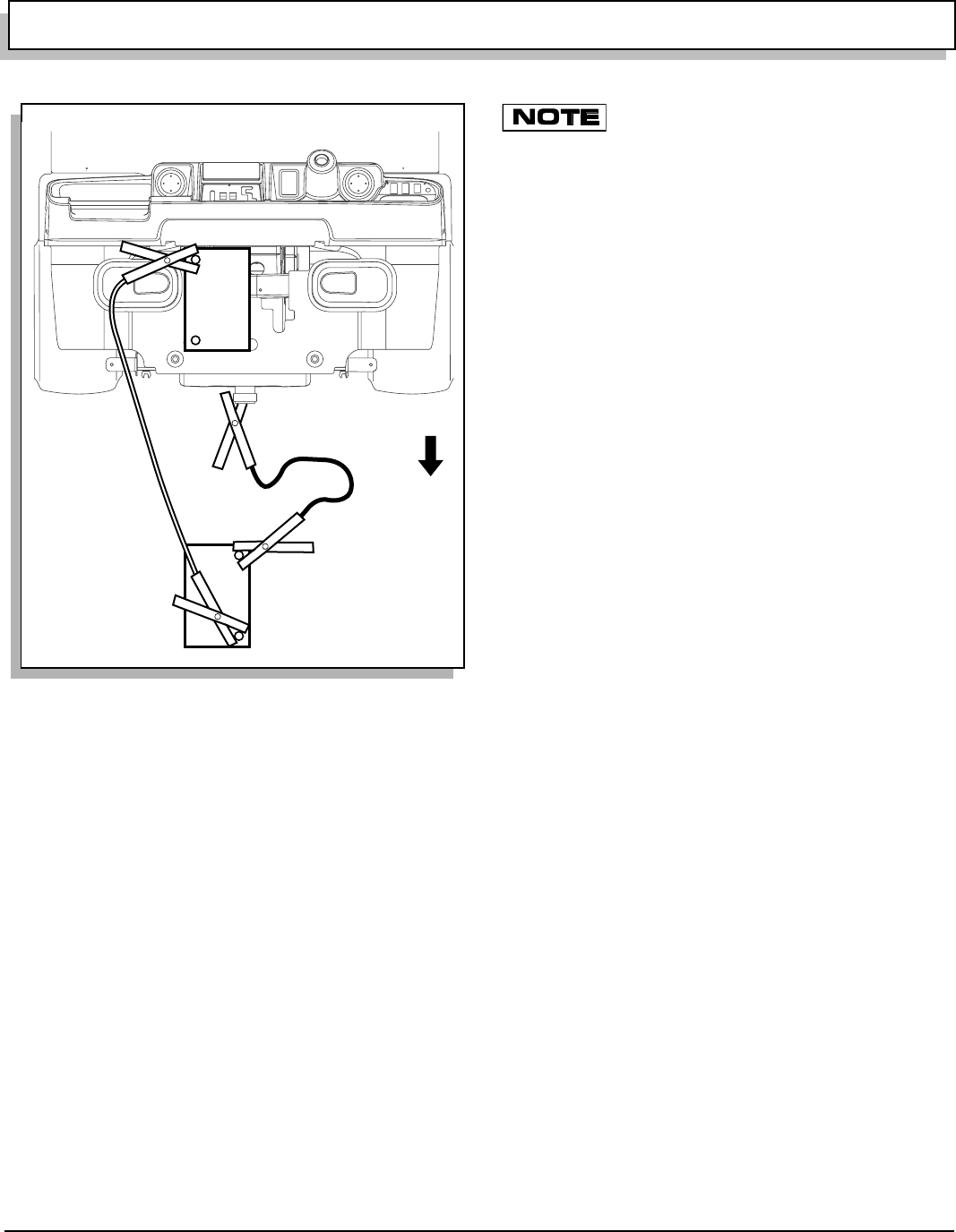
OPERATION AND SERVICE INFORMATION
Page 23
Owner’s Manual and Service Guide
Read all of manual to become thoroughly familiar with this vehicle. Pay particular attention to all Notes, Cautions and Warnings
tem. Do not use pressure in excess of 700 psi (4800 kPa)
to wash exterior of vehicle.
Clean windshield with lots of water and a clean cloth.
Normal cleaning of vinyl seats and plastic or rubber trim
requires use of a mild soap solution applied with a
sponge or soft brush and wipe with a damp cloth.
Removal of oil, tar, asphalt, shoe polish, etc. will require
use of a commercially available vinyl/rubber cleaner.
Painted surfaces require frequent washing with luke-
warm or cold water and mild detergent.
Occasional cleaning and waxing with non-abrasive prod-
ucts designed for ‘clear coat’ automotive finishes will
enhance the appearance and durability of the painted
surfaces.
Corrosive materials used as fertilizers or for dust control
can collect on underbody of vehicle. These materials will
cause corrosion of underbody parts unless flushed occa-
sionally with plain water. Thoroughly clean any areas
where mud or other debris can collect. Sediment packed
in closed areas should be loosened to ease it’s removal,
taking care not to chip or otherwise damage paint.
If engine does not start or runs improperly after
washing, remove spark plug wires (by pulling
the spark plug boots, never the wires). Dry all connections with
forced air. Reinstall wires.
CARE PRODUCTS
To help maintain the vehicle there are several products
available through local Distributors, authorized
Branches, or the Service Parts Department.
•Touch-up paint specially formulated to match vehi-
cle colors for use on both metal and molded plas-
tic bodies. (P/N 28140-G** and 28432-G** for
solid colors; 75831-G** for camouflage colors)
•Battery Protectant formulated to form a long-term,
flexible, non-tacky, dry coating that will not crack,
peel or flake over a wide temperature range. (P/N
75500-G01)
•White Lithium Grease designed to provide lubrica-
tion protection in areas where staining or discolor-
ing is a problem, or in areas of extreme
temperature ranges. (P/N 75502-G01)
•Penetrant/Lubricant, a 4-in-1 product that pene-
trates seized parts, lubricates leaving a light lubri-
cating film, reduces corrosion by adhering to wet
or dry surfaces and displaces moisture, sealing
against future moisture return. (P/N 75503-G01)
•Multi-purpose Cleaner and Degreaser that con-
tains natural, environmentally safe solvents. (P/N
75504-G01)
•Multi-purpose Hand Cleaner is an industrial
strength cleaner containing no harsh solvents, yet
gently lifts grease off hands. May be used with or
without water. (P/N 75505-G01)
•Battery Cleaner that neutralizes battery acids and
dissolves terminal corrosion and can be rinsed
with water. (P/N 75506-G01)
•Biodegradable Cleaner that breaks down grease
to be easily wiped or rinsed away. (P/N 75507-
G01)
•Multi-purpose Value Pack sampler includes 4
ounce (118 ml) aerosol cans of Battery Protector,
Penetrant/Lubricant, White Lithium Grease, and
Carburetor and Choke Cleaner. (P/N 75508-G01)
LABELS AND PICTOGRAMS
Vehicles are labeled with pictograms as a method of con-
veying information or warnings. Appendix A illustrates
and explains pictograms that appear on vehicle. Not all
pictograms shown in Appendix A will be used on vehicle.
Fig. 33 Jump Starting
Ref Jmp 1
+
-
+
-
Strong
Battery
Weak
Battery
Front o
f
Vehicle
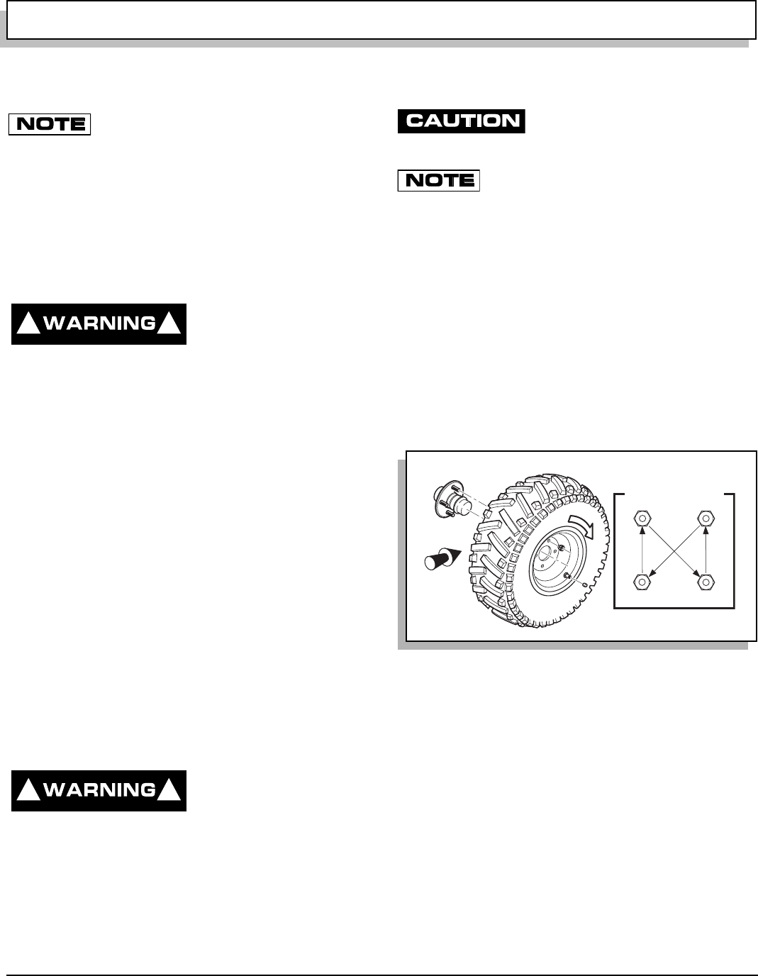
OPERATION AND SERVICE INFORMATION
Page 24 Owner’s Manual and Service Guide
Read all of manual to become thoroughly familiar with this vehicle. Pay particular attention to all Notes, Cautions and Warnings
WHEELS AND TIRES
Tires are uni-directional and should never be
moved from one side of vehicle to the other.
This vehicle comes standard with low pressure, tubeless,
uni-directional tires mounted on one piece wheels (Ref.
Fig. 34 on page 24). Left side tires should always remain
on left side of vehicle. Right side tires should always
remain on right side of vehicle. Uni-directional tires have
an arrow on their sidewall indicating direction of rotation
when moving forward.
TIRE INSPECTION AND INFLATION
To reduce possibility of
severe injury or death
from tire separating from
wheel or exploding, use caution when inflating tires
and never exceed maximum pressure rating on side-
wall of tire. Overinflation can occur quickly.
Tire condition should be inspected per the PERIODIC
SERVICE SCHEDULE See ‘PERIODIC SERVICE
SCHEDULE’ on page 15. Examine for cuts, punctures
and excessive wear. Repair or replace as necessary.
Air pressure should be checked when tires are cool. If air
needs to be added, see GENERAL SPECIFICATIONS
section of this manual. Standard and optional tires should
be inflated to pressure designated. If pressure is not des-
ignated, inflate to pressure recommended on sidewall of
tire. Under no condition should inflation pressure be
higher than maximum pressure listed on sidewall of tire.
All four tires should have the same pressure for opti-
mum handling characteristics.
Use caution when inflating tires. Due to low volume of
small tires, overinflation can occur in seconds. Overinfla-
tion could cause tire to separate from wheel or cause tire
to explode.
Be sure to install valve dust cap after checking.
REMOVAL AND INSTALLATION
To reduce possibility of
severe injury caused by
a broken socket when
removing wheels, use only sockets designed for
impact wrench use.
Hardware involved: 3/4" hex lug nut
To remove, loosen lug nuts. If using an impact wrench,
use only impact sockets with it. Regular sockets are not
designed for impact pressures exerted by power tools.
Raise vehicle. See LIFTING THE VEHICLE on page 17.
Remove lug nuts and wheel.
To reduce possibility of damage, tight-
en lug nuts to no more than 85 ft. lbs.
(115 Nm) torque.
Use ‘cross sequence’ pattern when tightening
lug nuts to assure even seating of wheel
against hub.
Special Tools Required Qty.
Torque wrench, ft. lbs. .................................................1
To install, place wheel onto studs with valve stem facing
away from hub (Ref. Fig. 34 on page 24). Be sure to
position wheel on hub correctly with arrow on tire indicat-
ing direction of rotation when moving forward.
Add lug nuts and finger tighten.
Secure wheel by tightening lug nuts in a ‘cross sequence’
pattern to 50 - 85 ft. lbs. (70 - 115 Nm) torque in 20 ft. lbs.
(30 Nm) increments.
Lower vehicle
.
! !
! !
Fig. 34 Wheel Tightening Sequence
Tire style may vary
1
2
3
4
'Cross Sequence'
Front of
Vehicle
R
o
t
a
t
i
o
n
Ref Whi 4
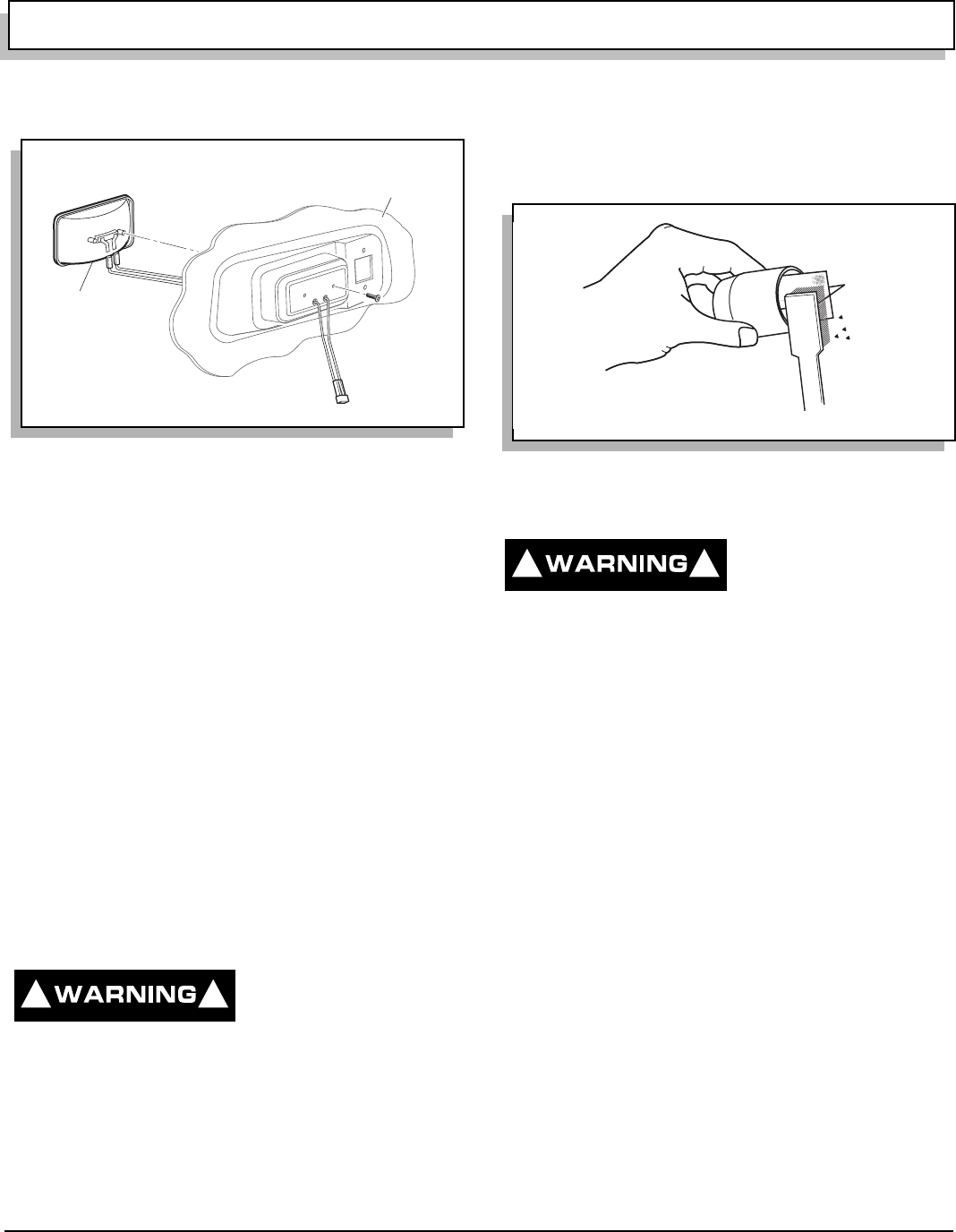
OPERATION AND SERVICE INFORMATION
Page 25
Owner’s Manual and Service Guide
Read all of manual to become thoroughly familiar with this vehicle. Pay particular attention to all Notes, Cautions and Warnings
LIGHT BULB REPLACEMENT
Replacement bulbs are available from a local Distributor,
an authorized Branch or the Service Parts Department
(Ref. Fig. 22 on page 16).
Locate two screws on backside of cowl that secure head-
light (Ref. Fig. 35 on page 25).
Remove screws, pull headlight out and disconnect wires.
Connect wires to new headlight, install in cowl and
secure with screws previously removed.
FUSE REPLACEMENT
Fuses are available from a local Distributor, an autho-
rized Branch or the Service Parts Department (Ref. Fig.
22 on page 16).
To replace fuses, locate fuse block or individual water
resistant fuses mounted to plate under cowl (late produc-
tion).
Pull out failed fuse and replace with a fuse of same type
and load rating.
SPARK ARRESTER
To reduce possibility of
severe injury or death,
allow muffler to cool
before servicing and never operate vehicle without
spark arrester in good condition and in place.
Raise load bed.
Remove screw securing spark arrester and pull arrester
from muffler (Ref. Fig. 36 on page 25).
Brush off carbon deposits from arrester screen without
damaging screen. Screen must be intact. Replace spark
arrester if screen is breached.
Install arrester on muffler and secure with screw.
PROLONGED STORAGE
To reduce possibility of
severe injury or death
resulting from a possi-
ble explosion:
Do not handle fuel in an area that is not adequately
ventilated. Do not smoke near fuel tank or refuel near
open flame or electrical items which could produce a
spark.
Store vehicle in a clean, dry area. Do not store in
same area as a stove, furnace, water heater, or other
appliance that uses a pilot light or has a device that
can create a spark.
When refueling, inspect fuel cap for leaks or breaks
that could result in fuel spillage.
Always wear safety glasses while refueling to prevent
possible eye injury from gasoline or gasoline vapor.
Keep hands, clothing and jewelry away from moving
parts. Use care not to contact hot objects.
Preparing vehicle for a prolonged storage period (30
days or more) calls for a few simple steps to prevent a
build up of varnish and gum in carburetor and corrosion
in engine.
•Clean body, chassis and engine of debris, mud,
chaff or grass (Ref. AIR INTAKE AND COOLING
FINS on page 26).
•Disconnect fuel hose at fuel tank and plug hose.
•With proper ventilation, start engine and allow it to
run until it stops due to lack of fuel.
Fig. 35 Headlight Replacement
Headlight
Bulb
Inside
of Cowl
R
ef Hdr 4
! !
Fig. 36 Cleaning Spark Arrester
Ref Csa 1
! !
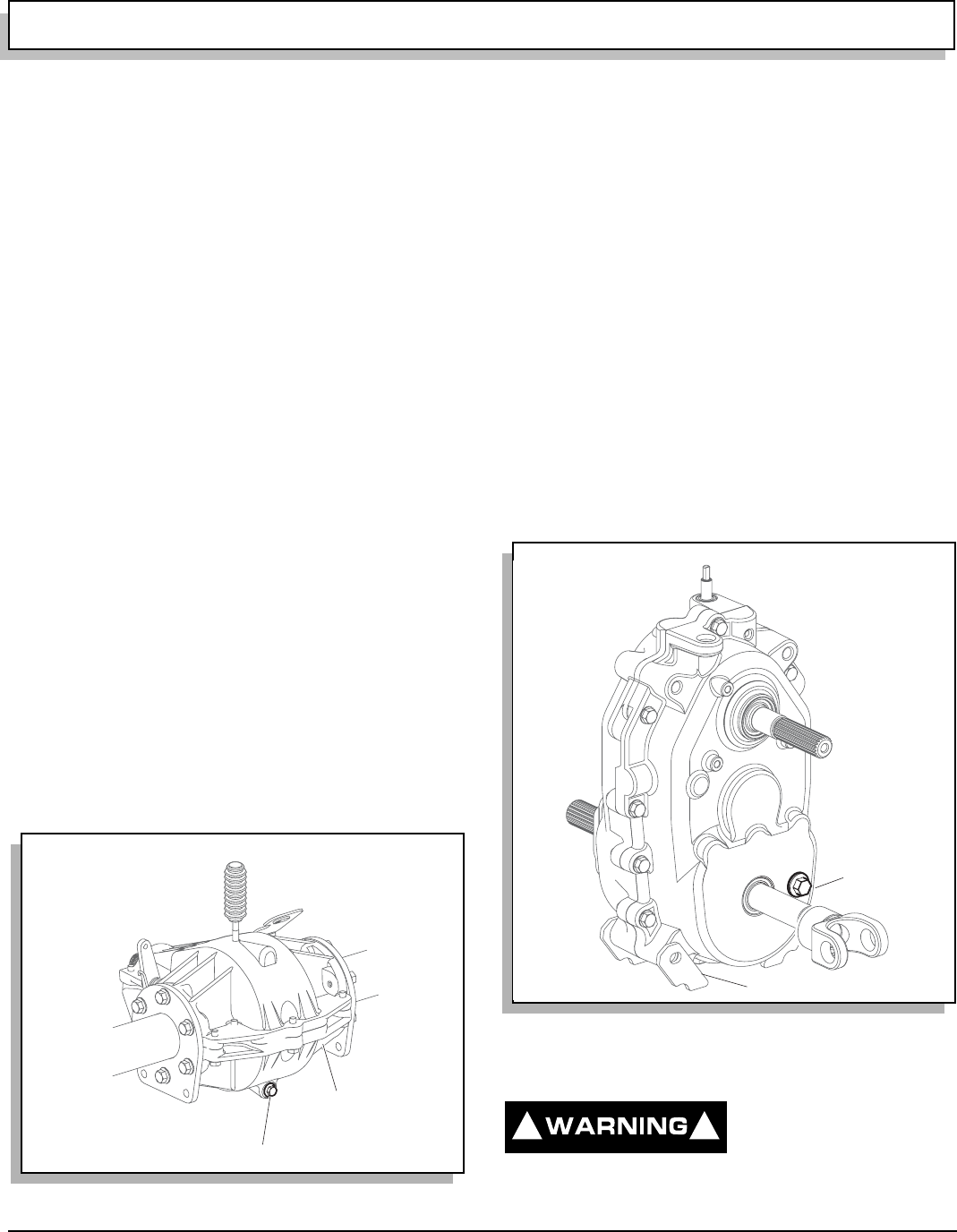
OPERATION AND SERVICE INFORMATION
Page 26 Owner’s Manual and Service Guide
Read all of manual to become thoroughly familiar with this vehicle. Pay particular attention to all Notes, Cautions and Warnings
•Add fuel stabilizer to fuel tank following instruc-
tions on stabilizer container.
•Attach fuel line to tank and drive vehicle for sev-
eral minutes to circulate fuel stabilizer through car-
buretor.
•While engine is still warm, change oil (Ref. OIL
CHANGE on page 18).
•Remove spark plugs (Ref. SPARK PLUGS on
page 19) and pour about 1 oz. (30 ml) of engine oil
into each cylinder. Replace spark plugs, ground
spark plug wires and use starter to turn engine
over a few seconds to distribute oil.
FRONT AND REAR AXLES
Rear axle is provided with a lubricant level check/fill plug
located on side of differential case. Unless leakage is evi-
dent, an annual lubricant check is sufficient.
CHECKING LUBRICANT LEVEL
Hardware involved: 7/16" hex head plug
Clean check/fill plug and area around it (Ref. Fig. 37 on
page 26).
Remove plug.
Correct lubricant level is just below bottom of threaded
hole. If lubricant is to be added, use a funnel and add
correct type lubricant slowly until it starts to seep from
hole See ‘Checking Axle Lubricant’ on page 26.
Install plug and tighten to 18 ft. lbs. (25 Nm).
To replace lubricant, a drain plug is provided at bottom of
differential case.
TRANSFER CASE
The transfer case is provided with an oil level check/fill
plug located on passenger side at rear of case. Unless
leakage is evident, an annual check is sufficient.
CHECKING LUBRICANT LEVEL
Hardware involved: 9/16" hex head plug
Clean check/fill plug and area around it (Ref. Fig. 38 on
page 26).
Remove plug.
Correct lubricant level is just below bottom of threaded
hole. If lubricant is to be added, use a funnel and add
correct type lubricant slowly until it starts to seep from
hole See ‘Checking Transfer Case Lubricant’ on page
26..
Install plug and tighten to 20 - 25 ft. lbs. (27 - 34 Nm).
To replace lubricant, a drain plug is provided at bottom of
transfer case.
AIR INTAKE AND COOLING FINS
To reduce possibility of
fire, engine parts should
be kept clean to reduce
risk of overheating and ignition of accumulated
debris.
Fig. 37 Checking Axle Lubricant
Check/Fill Plug
Drain Plug
Ref Raf 4
Fig. 38 Checking Transfer Case Lubricant
Drain Plug
Check/Fill Plug
Ref Tcf 1
! !
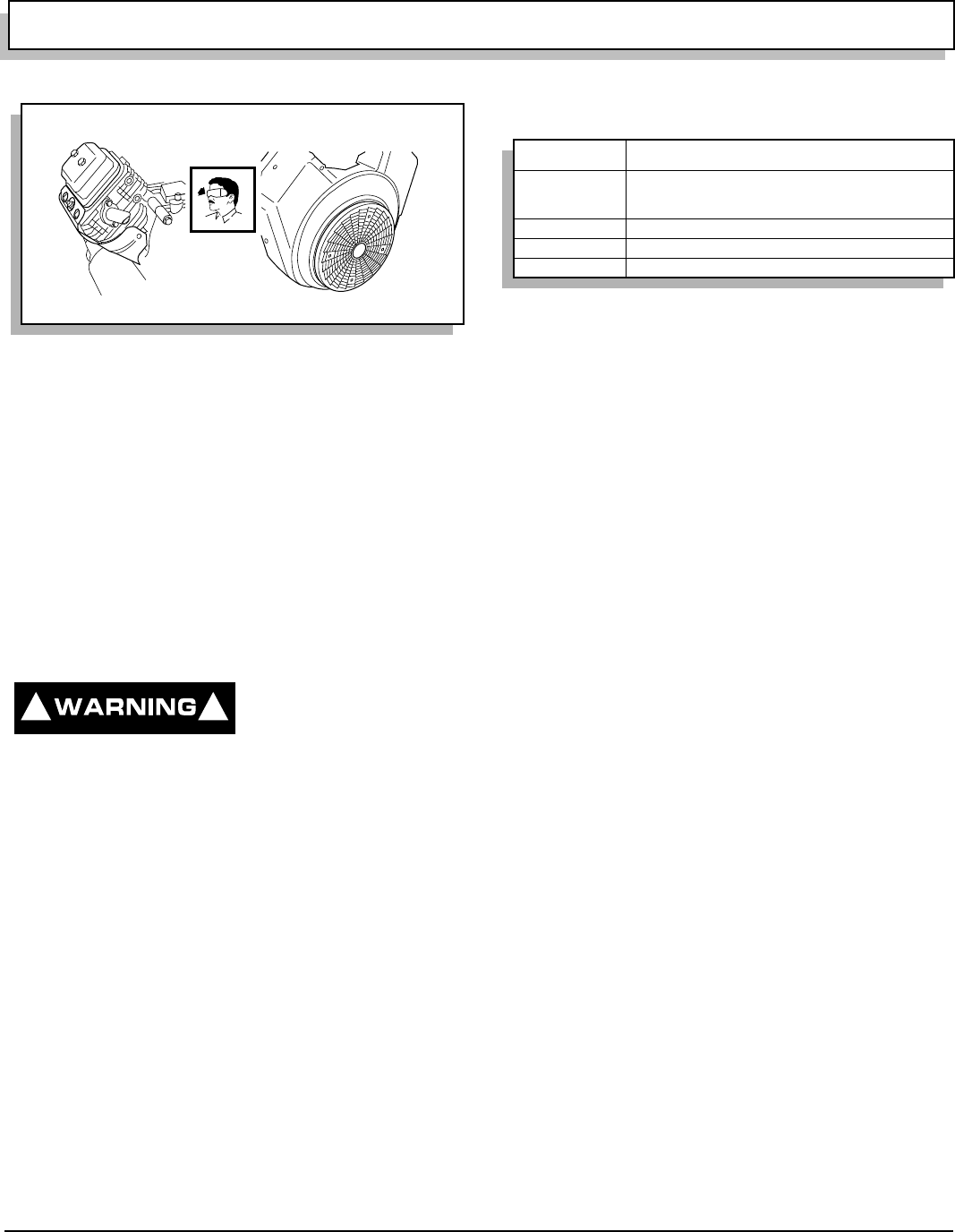
OPERATION AND SERVICE INFORMATION
Page 27
Owner’s Manual and Service Guide
Read all of manual to become thoroughly familiar with this vehicle. Pay particular attention to all Notes, Cautions and Warnings
After every off road use, allow to cool and then check for
build up of dirt and debris in air intake and cooling fins
(Ref. Fig. 39 on page 27). Dirt and debris may clog the
engine’s air cooling system.
Clean areas shown to prevent engine damage.
Keep linkages, springs and controls clean.
Keep area around muffler free of any combustible mate-
rial.
BRAKES
PERIODIC BRAKE TEST FOR HYDRAULIC
BRAKES
To reduce possibility of
severe injury or death,
always evaluate pedal
travel before operating a vehicle to verify some brak-
ing function is present.
It is important to periodically check and maintain proper
brake fluid level in master cylinder (Ref. BRAKES on
page 27). Master cylinder is located under cowl. When
checking fluid, wipe off any dirt from fill cap before
removing it to reduce possibility of contamination. Fluid
level should be maintained at mark molded into reservoir.
If fluid must be added, use only DOT 3 brake fluid and
inspect system for fluid leaks.
Push brake pedal. Pedal should have some free travel
and then become hard. A brake pedal that has no free
travel, excessive free travel or a spongy feel indicates
that a brake inspection is required. A brake pedal that
offers little resistance after it is applied indicates a leak in
system.
CAPACITIES
Fig. 39 Cleaning Air Intake and Cooling Fins
Air
Intake
Cooling
Fins
R
ef Cai 2
! !
Fuel Tank 6.7 gal (25.4 liters) unleaded, 87 octane or higher
Engine Oil 1.59 quarts (1.5 liters) crankcase only
1.90 quarts (1.8 liters) crankcase and filter
10W30 usually. See OIL on page 17.
Front Differential 15.2 ± 1 oz. (450 ml) of 80 - 90W GL5
Rear Axle 15.2 ± 1 oz. (450 ml) of 80 - 90W GL5
Transfer Case 24 oz. (700 ml) MOBILFLUID 424
Fig. 40 Capacities

OPERATION AND SERVICE INFORMATION
Page 28 Owner’s Manual and Service Guide
Read all of manual to become thoroughly familiar with this vehicle. Pay particular attention to all Notes, Cautions and Warnings
HARDWARE
Periodically, vehicle should be inspected for loose fasten-
ers. Fasteners should be tightened in accordance with
the Torque Specifications table (Ref. Fig. 41 on page 28).
Use care when tightening fasteners and refer to Techni-
cian’s Repair and Service Manual for specific torque val-
ues.
Generally, three grades of hardware are used in vehicle.
Grade 5 hardware can be identified by three marks on
the hexagonal bolt head and grade 8 by six marks.
Unmarked hardware is Grade 2.
Fig. 41 Torque Specifications and Bolt Grades
ALL TORQUE FIGURES ARE IN FT. LBS. (Nm)
BOLT SIZE
Grade 2
1/4" 5/16" 3/8" 7/16" 1/2" 9/16" 5/8" 3/4" 7/8" 1"
Unless otherwise noted in text, tighten all hardware in accordance with this chart.
This chart specifies 'lubricated' torque figures. Fasteners that are plated or lubricated when
installed are considered 'wet' and require approximately 80% of the torque required for 'dry' fasteners.
4
(5)
8
(11)
15
(20)
24
(33)
35
(47)
55
(75)
75
(102)
130
(176)
125
(169)
190
(258)
Grade 5
Grade 8
6
(8)
13
(18)
23
(31)
35
(47)
55
(75)
80
(108)
110
(149)
200
(271)
320
(434)
480
(651)
6
(8)
18
(24)
35
(47)
55
(75)
80
(108)
110
(149)
170
(230)
280
(380)
460
(624)
680
(922)
BOLT SIZE
Class 5.8
(Grade 2)
M4 M5 M6 M8 M10 M12 M14
1
(2)
2
(3)
4
(6)
10
(14)
20
(27)
35
(47)
55
(76.4)
Class 8.8
(Grade 5)
2
(3)
4
(6)
7
(10)
18
(24)
35
(47)
61
(83)
97
(131)
Class 10.9
(Grade 8)
3
(4)
6
(8)
10
(14)
25
(34)
49
(66)
86
(117)
136
(184)
5.8
8.8
10.9
Ref Tsp 1

Page 29
GENERAL SPECIFICATIONS
Owner’s Manual and Service Guide
GENERAL SPECIFICATIONS

Page 30 Owner’s Manual and Service Guide
GENERAL SPECIFICATIONS
ST 4X4
STANDARD EQUIPMENT:
CHASSIS Welded steel, hot-dip galvanized, front hitch receiver
BODY (Front) Flexible, Impact Resistant DuraShield™ Injection Molded TPE
(Thermoplastic Elastomer) with Base Coat/Clear Coat
BODY (Rear) Lightweight, replaceable steel panels, plastic rear fenders
BATTERY One 12 Volt Maintenance Free (340 CCA, 38 Minute Reserve)
ENGINE Honda 18 H.P. (13.4 kW) 37.5 ci (614 cc) Twin Cylinder, Air Cooled, Overhead Valve,
Replaceable Oil Filter, Replaceable Dry Cartridge Air Filter with Remote Air Intake,
Transistorized Magneto, Fixed Jet Bowl Carburetor, Pulse Fuel Pump
TRANSFER CASE Helical geared with Forward, Reverse and Ground Speed Governor
TRANSMISSION Automatic Continuously Variable Transmission (CVT)
FUEL TANK 6.7 Gallon (25.4 Liters) Tank
BRAKES (FRONT) Dual Front Wheel, Hydraulic 8" (203 mm) Disc Brakes
BRAKES (REAR) Dual Rear Wheel, Hydraulic 6.3" (160 mm) Drum Brakes
PARK BRAKE Hand Operated Lever with Indicator Light
FRONT SUSPENSION Independent with Hydraulic Struts
REAR SUSPENSION Leaf Springs with Hydraulic Shock Absorbers
STEERING Single Reduction Rack & Pinion
SEATING Cushion Foam/Vinyl Cover, Hip Restraint/Hand Hold
SEATING CAPACITY Operator & 1 Passenger
TOTAL LOAD CAPACITY 1500 lbs. (545 kg) Including Operator, Passenger, Accessories & Cargo
SPEED 25 mph (40 kph)
STANDARD COLOR Recon Green
DASH PANEL Scuff Resistant Glass Fiber Reinforced Plastic (Thermoplastic Olefin) with 2 Drink Holders
TIRE Carlisle AT489, 25 x 11 - 12 (Uni-directional)
TIRE PRESSURE 16 - 20 psi (110 - 138 kPa)
WEIGHT (Without fuel) 1250 lbs. (567 kg)
BED Rotomolded Load Bed, Inside Dimensions: 42 3/4" L X 54" W X 11" H (109 X 137 X 27 cm)
OPERATING CONTROLS & Removable Key, Direction Selector, Electric Fuel Gauge, 4WD/2WD Selector with Indicator Lights,
INSTRUMENTATION Electric Front & Rear Differential Locks with Indicator Lights, Hour Meter, Volt Meter
MAXIMUM TRAILER WEIGHT 1500 lbs. (680 kg)
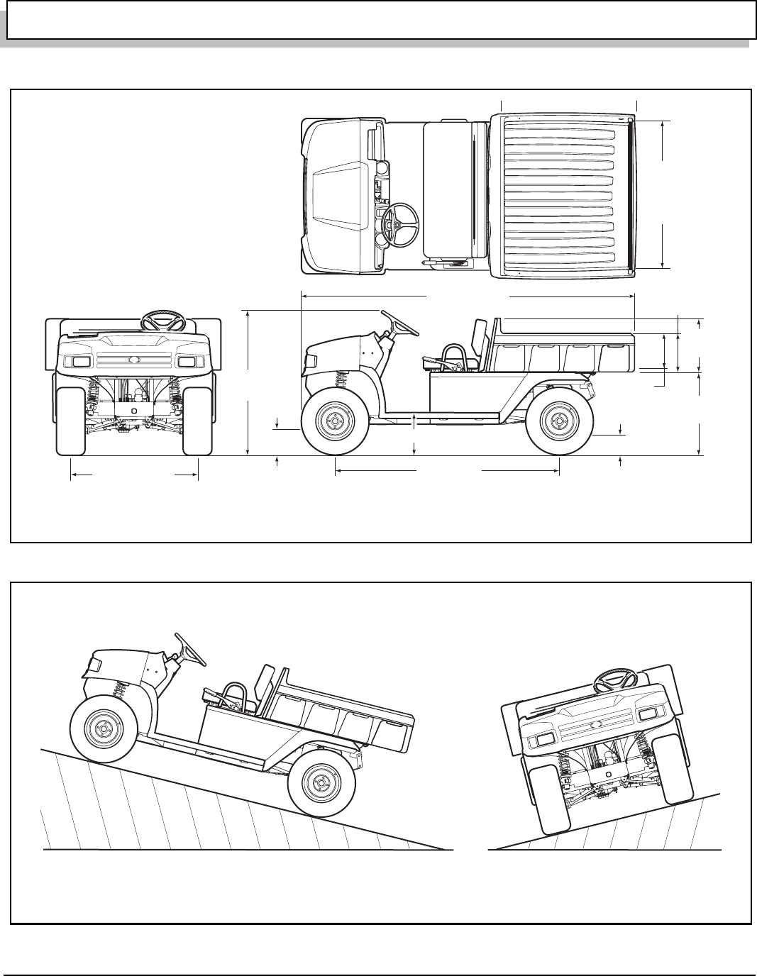
Page 31
GENERAL SPECIFICATIONS
Owner’s Manual and Service Guide
Fig. 42 Vehicle Dimensions
Fig. 43 Vehicle Incline Specifications
Front
43 3/8" (110 cm)
Rear
43 3/4" (111 cm)
76" (193 cm)
112" (285 cm)
50"
(127 cm)
16" (40.6 cm)
8 3/8" (21.3 cm)
Clearance At Lowest Point
Of Vehicle (On Rear Axle)
31.5"
(80 cm)
54" *
(137 cm)
50"
(127 cm)
11"
(28 cm)
(Inside)
11 1/2"
(29 cm)
12 3/4" *
(32 cm)
18 1/4"
(46 cm)
9 1/2" (24 cm)
Clearance At Lowest
Point On Frame
Ref Dim 3-1 Late 2005 Production Loadbed shown. Early Production Similar
* Indicates Late 2005 Production Dimension
Maximum Recommended Side Tilt
25% or 14˚ Max.
Maximum Recommended Ramp Grade
25% or 14˚ Max.
Ref Dim 3-2
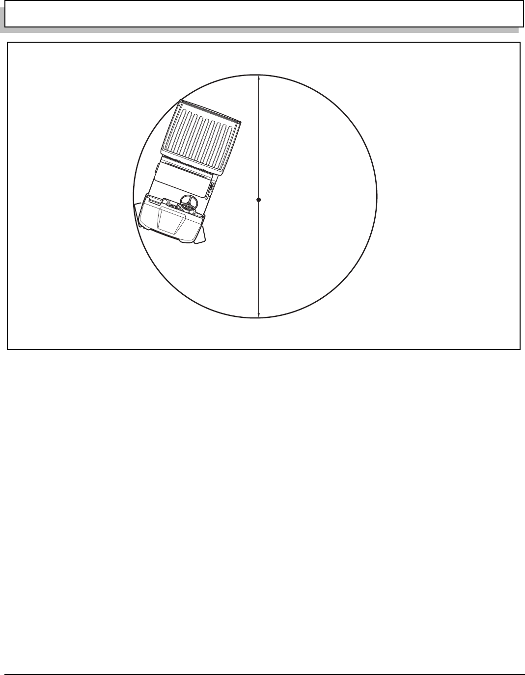
Page 32 Owner’s Manual and Service Guide
GENERAL SPECIFICATIONS
Fig. 44 Vehicle Turning Clearance Diameter and Intersecting Aisle Clearance
TURNING CLEARANCE DIAMETER
Approx. 25'-6" (7.8 m)
Ref Dim 3-3

Page 33
Owner’s Manual and Service Guide
VEHICLE WARRANTIES
VEHICLE WARRANTIES

Page 34 Owner’s Manual and Service Guide
VEHICLE WARRANTIES

Page 35
VEHICLE WARRANTIES
Owner’s Manual and Service Guide
EMISSION CONTROL SYSTEM WARRANTY STATEMENT
(Owner’s Defect Warranty Rights and Obligations)
Refer to the HONDA Emission Control System Warranty sheet, provided with vehicle, for information.
ENGINE OWNER WARRANTY POLICY
Refer to the Warranty sheet, provided with vehicle, for Engine Warranty information.
INTERNATIONAL WARRANTY STATEMENT
Refer to the International Warranty sheet, provided with vehicle, for information.

Page 36 Owner’s Manual and Service Guide
VEHICLE WARRANTIES
N
otes:

Page 37
Owner’s Manual and Service Guide
DECLARATION OF CONFORMITY
DECLARATION OF CONFORMITY
(EUROPE ONLY)
Declaration of Conformity is packaged with vehicle. For additional information, contact:
Ransomes Jacobsen Limited
West Road, Ransomes Europark,
Ipswich, England, IP3 9TT

Page 38 Owner’s Manual and Service Guide
DECLARATION OF CONFORMITY
N
otes:

Appendix A - 1
LABELS AND PICTOGRAMS
Owner’s Manual and Service Guide
LABELS AND PICTOGRAMS

Appendix A - 2 Owner’s Manual and Service Guide
LABELS AND PICTOGRAMS
Notes:
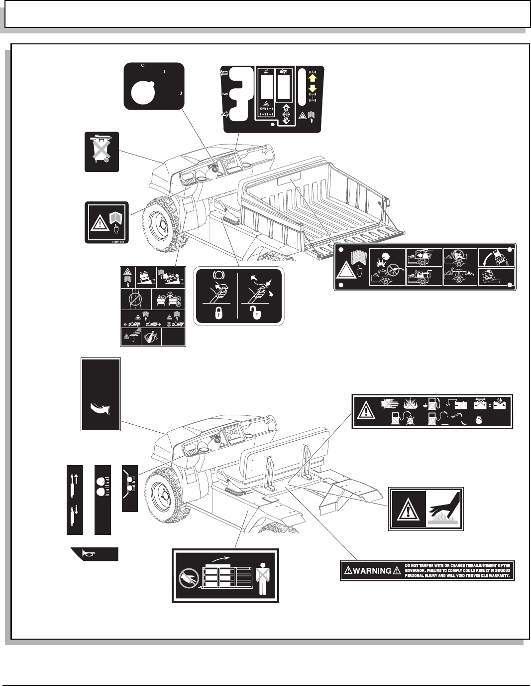
Appendix A - 3
LABELS AND PICTOGRAMS
Owner’s Manual and Service Guide
Fig. 45 Label Locations
75696G01
74099G01
See Following
Pages For
Explanation
Of These
Pictograms:
(14)
74099-G01
72939G01
(Lift Cowl)
To release cowl,
raise and hold
cowl, lift lever
and lower cowl
carefully
72939G01
H O
2
123
P
P
P
P
P
P
74093-G01
74093G01
24880G1
75696G01
See Following Pages
For Explanation Of These
Pictograms: (1,23,27,18,20,
22,17,15)
See Following Pages
For Explanation Of These
Pictograms: (1)
See Following
Pages For
Explanation
Of These
Pictograms:
(1,35)
73603G01
73601G01
73605G01
73607G01
See Following
Pages For
Explanation
Of These
Pictograms:
(61,45,62,63)
See Following Pages
For Explanation Of
These Pictograms:
(43,44,51)
73767G01
73771G01
See Following
Pages For
Explanation
Of These
Pictograms:
(1,2,3,4,6,9,29,
36,37,54,55)
< 14
˚
25%
< 14
˚
25%
73771G01
OFF
ON
START
73767G01
73769 G01
See Following
Pages For
Explanation
Of These
Pictograms:
(52,53)
P
12
3
73769G01
35493G01
See Following Pages
For Explanation Of
This Pictogram:
(28)
(Lift Cowl)
P
b
35493-G01
74821G04 See Following
Pages For
Explanation
Of These
Pictograms:
(1,2,12,10,8,
11,50,7,5)
MA
X
14
o
/ 25
%
!
MA
X
1100 l
b
s.
500 k
g
MA
X
5 i
n
.
12 c
m
P
P
MA
X
100 l
b
s.
45 k
g
74821G04
See Following
Pages For
Explanation
Of These
Pictograms:
(56,57,58,59,60)
73777G01
73777G01
71489G01
See Following Pages
For Explanation Of
These Pictograms:
(1,2)
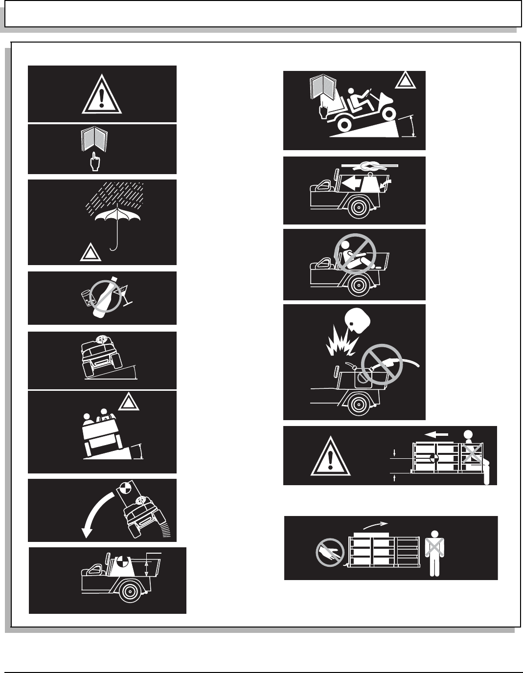
Appendix A - 4 Owner’s Manual and Service Guide
LABELS AND PICTOGRAMS
Fig. 46 Pictogram Definitions
1.
2.
4.
MAX
MAX
14 ° / 25 %
14 ° / 25 %
5.
!
< 14 ° 25 %
< 14 ° 25 %
6.
P
P
12.
x in
x in
xx cm
xx cm
MAX LOAD
MAX LOAD
XXX LBS
XXX LBS
XXX KG
XXX KG
13.
!
< 14 ° 25 %
< 14 ° 25 %
9.
11.
7.
MAX
MAX
xxx lbs.
xxx lbs.
xxx kg
xxx kg
10.
MAX
MAX
xx in
xx in
xx cm
xx cm
8.
!
3.
WARNING
DO NOT OPERATE
UNDER THE INFLUENCE
OF DRUGS OR ALCOHOL
14.
WARNING
READ MANUAL
WARNING
USE CAUTION
IN INCLEMENT
WEATHER
MAXIMUM CROSS
HILL/RAMP ANGLE
AS SPECIFIED
WARNING
MAXIMUM CROSS
HILL/RAMP ANGLE
AS SPECIFIED
LOAD WITH
HIGH CENTER
OF GRAVITY
COULD RESULT
IN TIP OVER
LOAD
CENTER
OF GRAVITY,
MAXIMUM
HEIGHT
WARNING
READ MANUAL
FOR MAXIMUM
LOAD BED
CAPACITY.
MAXIMUM
RAMP/HILL
SECURE LOAD
AS FAR FORWARD
AS POSSIBLE
MAXIMUM LOAD
BED CAPACITY
DO NOT RIDE IN
LOAD BED
DANGER OF
EXPLOSION
DO NOT FILL
GAS CAN
IN LOAD BED
WARNING MAXIMUM LAOD & CENTER OF GRAVITY.
KEEP LOAD AS FAR FORWARD AS POSSIBLE.
DO NOT RIDE IN LOAD BED
KEEP HANDS & FINGERS AWAY FROM DUMP BED.
DO NOT STAND BEHIND DUMP BED
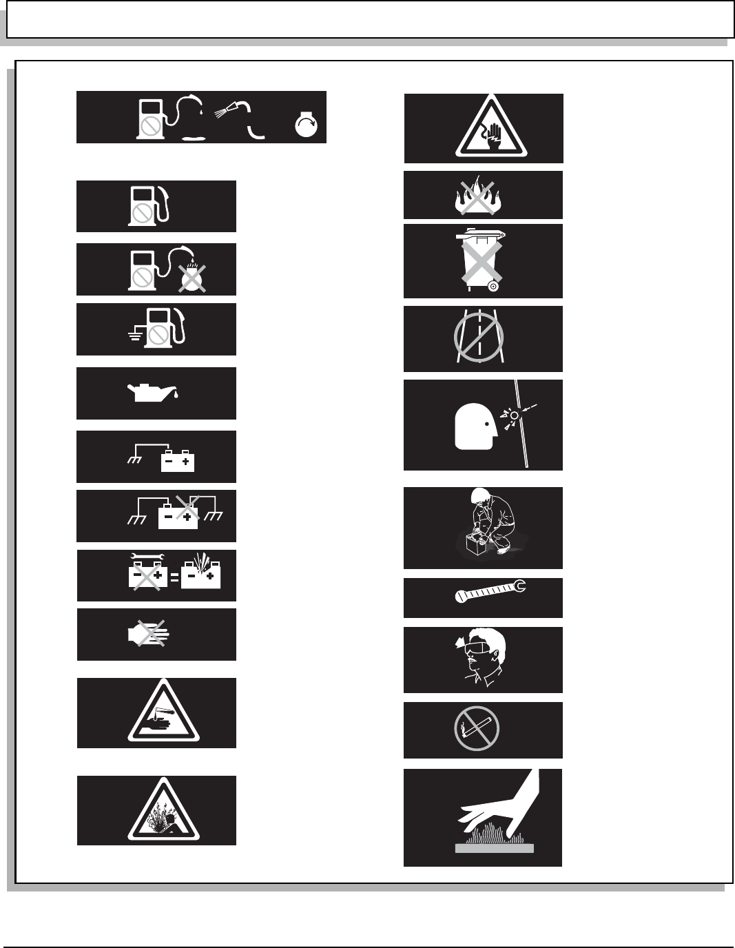
Appendix A - 5
LABELS AND PICTOGRAMS
Owner’s Manual and Service Guide
Fig. 47 Pictogram Definitions
26.
27.
13
H O
2
P
P
15.
2
P
P
16.
P
P
18.
P
P
17.
23.
21.
22.
24.
25.
19.
20.
28.
29.
30.
31.
32.
33.
34.
35.
CLEAN UP GASOLINE SPILLS WITH WATER BEFORE
STARTING ENGINE
UNLEAD
GASOLINE
DO NOT
SPILL FUEL
ON A HOT
ENGINE
GROUND
FUEL PUMP
LOW OIL PRESSURE
NEGATIVE
GROUND
BATTERY
DO NOT CONNECT
POSITIVE BATTERY
TERMINAL TO GROUND
SHORTING BATTERY
TERMINALS MAY
CAUSE EXPLOSION
NO
TAMPERING.
KEEP HANDS
OUT
WARNING
CORROSIVE
WARNING
EXPLOSIVE
WARNING
LETHAL
VOLTAGE
DO NOT
EXPOSE
TO FLAME
DO NOT
DISPOSE OF
BATTERIES
IN LANDFILL
DO NOT
DRIVE ON
HIGHWAY
WINDSHIELDS
DO NOT
PROVIDE
PROTECTION
FROM
FLYING OBJECTS
BATTERIES ARE
HEAVY.
USE CARE LIFTING
USE INSULATED
TOOLS
WEAR EYE
PROTECTION
NO SMOKING
HOT SURFACE
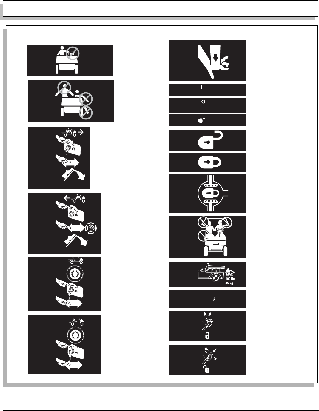
Appendix A - 6 Owner’s Manual and Service Guide
LABELS AND PICTOGRAMS
Fig. 48 Pictogram Definitions
36.
37.
F
38.
42.
R
39.
P
F
40.
P
N
41.
ON
43.
OFF
44.
45.
46.
47.
48.
49.
50.
51.
START
52.
P
53.
12
3
OPERATE
FROM
DRIVER’S SIDE
ONLY
KEEP ARMS
AND LEGS
WITHIN VEHICLE
TO OPERATE VEHICLE IN FORWARD:
* TURN KEY TO ON
* MOVE DIRECTION SELECTOR TO
FORWARD
* DEPRESS ACCELERATOR PEDAL
AND ACCELERATE SMOOTHLY
TO OPERATE VEHICLE IN REVERSE:
* TURN KEY TO ON
* MOVE DIRECTION SELECTOR TO
REVERSE
* AN AUDIBLE DEVICE WILL SOUND
* DEPRESS ACCELERATOR PEDAL
AND ACCELERATE SMOOTHLY
TO LEAVE A GASOLINE POWERED
VEHICLE IN PARK:
* APPLY PARKING BRAKE
* TURN KEY TO OFF
* MOVE DIRECTION SELECTOR TO
FORWARD
TO LEAVE AN ELECTRIC POWERED
VEHICLE IN PARK:
* APPLY PARKING BRAKE
* TURN KEY TO OFF
* MOVE DIRECTION SELECTOR TO
NEUTRAL
PULL HANDLE UP,
PUSH BUTTON IN,
PUSH HANDLE DOWN
TO RELEASE PARK BRAKE
PULL HANDLE UP
TO ENGAGE PARK
BRAKE
ENGINE
CRANKING
POSITION
MAXIMUM
TAILGATE
LOAD
WARNING
KEEP ENTIRE BODY
INSIDE CAR
DIFFERENTIAL
LOCKED
LOCKED
UNLOCKED
KEEP CLEAR
HAND OR
FINGERS CAN
BE TRAPPED
ON
POSITION
OFF
POSITION
HEADLIGHTS
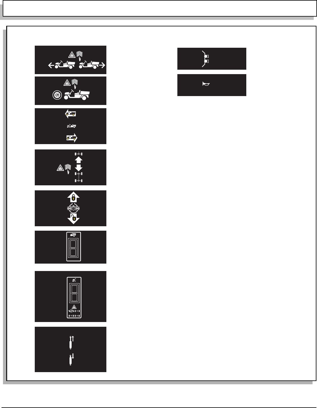
Appendix A - 7
LABELS AND PICTOGRAMS
Owner’s Manual and Service Guide
Fig. 49 Pictogram Definitions
62.
63.
56.
57.
58.
59.
60.
61.
55.
54.
WARNING
READ OWNER’S MANUL
BEFORE OPERATING
VEHICLE IN FORWARD
OR REVERSE
WARNING
READ OWNER’S MANUAL
BEFORE PARKING
VEHICLE AND LEAVING
IT UNATTENDED
FORWARD
NEUTRAL
REVERSE
WARNING
READ OWNER’S MANUAL
BEFORE ENGAGING TWO
OR FOUR WHEEL DRIVE
PUSH TOP OF SWITCH
TO LOCK DIFFERENTIAL
PUSH BOTTOM OF
SWITCH TO UNLOCK
DIFFERENTIAL
FRONT DIFFERENTIAL
LOCK SWITCH.
WARNING
READ OWNER’S MANUAL
BEFORE ENGAGING
FRONT DIFFERENTIAL
LOCK.
DO NOT ENGAGE LOCK
WHILE FRONT WHEELS
ARE TURNED AND
VEHICLE IS AT SPEED.
PUSH TOP PART OF
SWITCH TO RAISE LOAD
BED
PUSH BOTTOM PART OF
SWITCH TO LOWER LOAD
BED
REAR DIFFERENTIAL
LOCK SWITCH
AUXILIARY LIGHTS
HORN BUTTON

Appendix A - 8 Owner’s Manual and Service Guide
LABELS AND PICTOGRAMS
Notes:

Check area behind the
vehicle before operating
in reverse.
Make sure the direction selector is in correct position
before attempting to start the vehicle.
Slow down before and during turns. All turns should
be executed at reduced speed.
Always bring vehicle to a complete stop before
shifting the direction selector.
See GENERAL SPECIFICATIONS for vehicle load and
seating capacity.
Read and understand the following text and
warnings before attempting to service vehicle:
In any product, components will eventually fail to perform
properly as the result of normal use, age, wear or abuse.
It is virtually impossible to anticipate all possible compo-
nent failures or the manner in which each component
may fail.
Be aware that a vehicle requiring repair indicates that the
vehicle is no longer functioning as designed and there-
fore should be considered potentially hazardous. Use
extreme care when working on any vehicle. When diag-
nosing, removing or replacing any components that are
not operating correctly, take time to consider the safety of
yourself and others around you should the component
move unexpectedly.
Some components are heavy, spring loaded, highly cor-
rosive, explosive or may produce high amperage or
reach high temperatures. Gasoline, carbon monoxide,
battery acid and hydrogen gas could result in serious
bodily injury to the technician/mechanic and bystanders if
not treated with the utmost caution. Be careful not to
place hands, face, feet or body in a location that could
expose them to injury should an unforeseen situation
occur.
Always use the appropriate tools listed in the tool list and
wear approved safety equipment.
To prevent personal
injury or death, observe
the following:
Before working on the vehicle, remove all jewelry
(rings, watches, necklaces, etc.)
Be sure that no loose clothing or hair can contact
moving parts.
Use care not to touch hot objects.
Raise entire vehicle and support on jack stands before
attempting to run or adjust powertrain.
Wear eye protection when working on or around
vehicle. In particular, use care when working around
batteries, using solvents or compressed air.
Hydrogen gas is formed when charging batteries. Do
not charge batteries without adequate ventilation.
Do not permit open flame or anyone to smoke in an
area that is being used for charging batteries. A
concentration of 4% hydrogen gas or more is
explosive.
Engine exhaust gas (carbon monoxide) is deadly.
Carbon monoxide is an odorless, colorless gas that is
formed as a natural part of incomplete combustion of
hydrocarbon fuels. Carbon monoxide is a dangerous
gas that can cause unconsciousness and is
potentially lethal.
The following are symptoms of carbon monoxide
inhalation:
• Dizziness
• Vomiting
• Intense headache
• Muscular twitching
• Weakness and sleepiness
• Throbbing in temples
If any of these symptoms are experienced, get fresh air
immediately. Never work around or operate a vehicle
in an environment that does not ventilate exhaust
gases from the area.
! !
! !

Copyrighted Material
This manual may not be reproduced in whole or
in part without the express permission of
E-Z-GO Division of Textron, Inc.
Technical Communications Department
Starting Model Year 2005
P/N 602080
ISSUED: April 2005
E-Z-GO Division Of Textron, Inc.,
1451 Marvin Grin Road, Augusta, Georgia USA 30906-3852
TO CONTACT US
North America:
Technical Assistance & Warranty Phone: 1-800-774-3946, FAX: 1-800-448-8124
Service Parts Phone: 1-888-GET-EZGO (1-888-438-3946), FAX: 1-800-752-6175
International:
Phone: 010-1-706-798-4311, FAX: 010-1-706-771-4609
