E2V Technologies DTX2400 LRT Transmitter module for use with Thermal Image Camera User Manual das762156aa 11 s1
E2V Technologies Ltd. LRT Transmitter module for use with Thermal Image Camera das762156aa 11 s1
User manual
USER GUIDE FOR ARGUS®4 VIDEO ACCESSORIES

©e2v technologies (uk) limited 2010 107553 09 Aug 2010 DAS762156AA (UK) Version 11, page 1
THERMAL IMAGING VIDEO ACCESSORIES
SAFETY NOTES
Before using this product, the customer shall read and understand all the
instructions and warnings. e2v technologies does not accept responsibility for
damage or injury resulting from failure to follow the instructions provided.
WARNINGS:
• The Argus®4 Video Accessories are despatched from e2v technologies in a
safe condition. Any unauthorised modifications may compromise safety
and invalidate the warranty.
• The Argus®4 Video Accessories are not certified as intrinsically safe and
therefore must not be operated in potentially flammable or explosive
atmospheres.
• All users must be trained in the correct operation, functionality and features
of the Argus®4 before use.
• The Argus®4 Video Accessories can only be serviced by authorised
personnel. There are no end-user serviceable parts except those described
in the maintenance section of this manual.
• The Argus®4 LRT receiver contains a Lithium Ion battery. Do not allow the
receiver to become heated above 80°C or subjected to extreme impact.
• Neglecting the above may result in injury or death.
LIMITATION OF USE:
The Argus®4 Video Accessories are not certified for automotive use in immunity-
related functions. It MUST NOT be used for the control of a vehicle, a vehicular
safety system or in a way that may disturb the driver, data bus or statutory devices
fitted to a vehicle.
All matters arising, which relate to the safety of this product, should be reported
immediately in writing, giving full details, to the Quality Engineering Manager at e2v
technologies.

©e2v technologies (uk) limited 2010 107553 09 Aug 2010 DAS762156AA (UK) Version 11, page 2
RADIO COMPLIANCE
Before using any transmitter accessory read the notes in sections 14, 15 & 16
appropriate to the product and country of use.
It is the users’ responsibility to ensure that the frequency and power of operation are
permitted in their locale.
Failure to do so may result in illegal radio operation and prosecution.
ENVIRONMENTAL
e2v technologies declares that the Argus®4 Video Accessories
comply with EC directive 2002/95/EC (the RoHS Directive) restricting
the use of certain hazardous materials in electrical and electronic
equipment.
The Argus®4 Video Accessories are classified as Electronic and
Electrical Equipment according to directive 2002/96/EC (the WEEE
Directive) and should be segregated from domestic waste for
disposal. Contact your local e2v sales office for disposal instructions.
The P7030TX, P7030VC and P7030DTX contain a NiMH battery.
Do not crush or dispose of in fire.
The DRX and DRRS products contain a Li-Ion battery.
Do not crush or dispose of in fire.
China RoHS: This product does not contain toxic or hazardous
substances or elements over the maximum permitted concentration
values. Refer to the Argus®4 Thermal Image Camera customer
information CD for more information.
本产品不含有毒、有害物质或其浓度在允许范围内。详细信息请查阅
随附的用户信息光盘
©e2v technologies (uk) limited 2010 107553 09 Aug 2010 DAS762156AA (UK) Version 11, page 3
USER GUIDE FOR THE ARGUS®4 VIDEO ACCESSORIES
This document explains to the user how to operate the Argus®4 External Video
Accessories and applications for their use.
Contents
1 General Overview
2 Transmitter and Battery Pack
3 Receiver
4 Receiver Kit
5 External Power and Video Adaptor
6 Analogue Output Battery Pack
7 Video Capture Battery Pack
8 LRT System
9 Installing the Ateme player
10 Applications and Advanced use
11 FAQ
12 Specifications
13 FCC Statement (All products applicable in USA and Canada)
14 Compliance and Legal Notices (P7030TX Transmitter)
15 Compliance and Legal Notices (DTX1400 LRT Transmitter)
16 Compliance and Legal Notices (DTX2400 LRT Transmitter)
17 Warranty
©e2v technologies (uk) limited 2010 107553 09 Aug 2010 DAS762156AA (UK) Version 11, page 4
SECTION 1 – General Overview
The main applications for the Argus™4 video accessories are in remote
command overview, training, evidence gathering and investigation. The user
is offered a number of different solutions for viewing the camera images at a
distance and for recording video from the camera. The user can choose
between a fully configured system and the option to use the camera with
existing equipment or to build a more complex system.
The main departure from existing systems is that the camera has an output is
in a computer-friendly format for the digital age allowing the use with standard
networking equipment directly to a computer, providing files ready for use
without the need for conversion.
Additionally, analogue output is present on many camera variants allowing use
with existing standard video equipment through the analogue accessories.
The LRT accessories offer a very high performance video link that is also
secure and can be interfaced with systems in use in command vehicles for
other video cameras
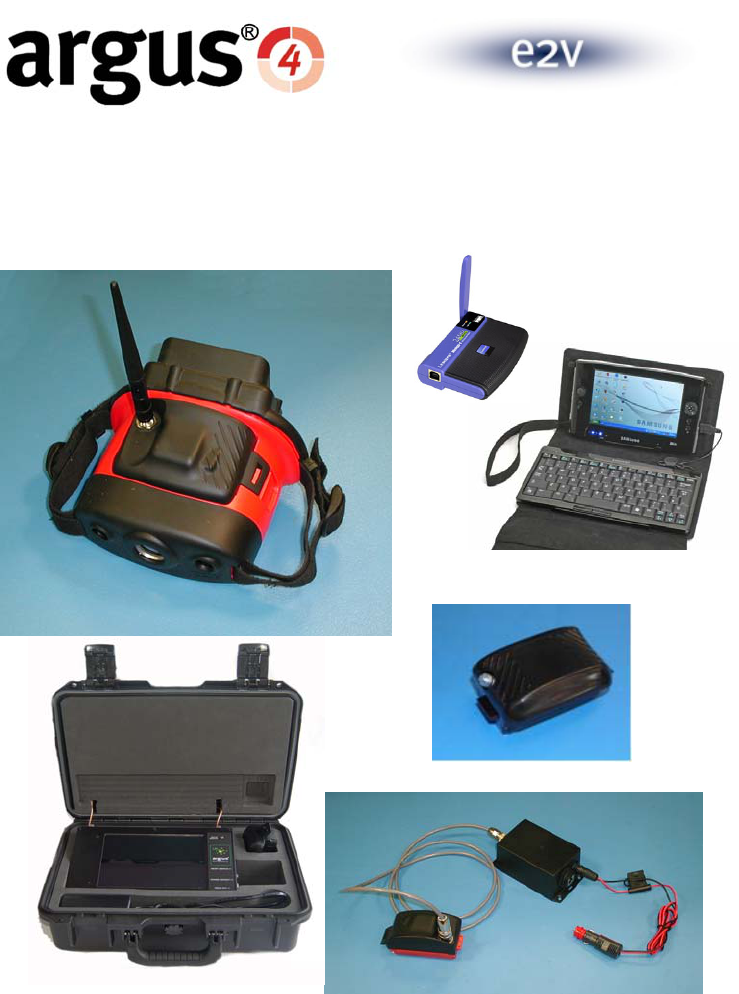
WiFi system P7030TX, P7030RRS and
P7030RKT Sections 2,3 & 4
From page 3
Wired Systems P7030EPVA, P7030AVBP Sections 5 & 6
From page 14
Recorder P7030VC Section 7
From page 20
LRT System DTX1400 / DRX1400 /
DRRS1400
DTX2400 / DRX2400 /
DRRS2400
Section 8
From page 23
©e2v technologies (uk) limited 2010 107553 09 Aug 2010 DAS762156AA (UK) Version 11, page 5
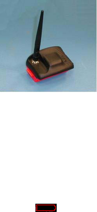
SECTION 2 - Argus®4 Transmitter and Battery Pack P7030TX
This accessory allows an Argus®4 camera to transmit video over Wi-Fi to a suitable receiver and
to be viewed on a computer connected to it. This is incorporated in a battery pack that provides
power for both transmitter and camera.
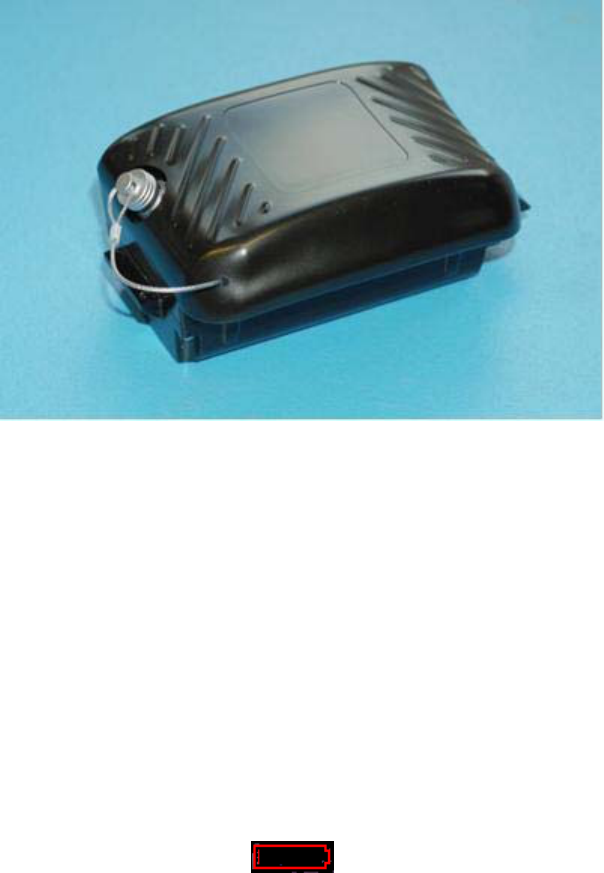
The Transmitter and battery pack consists of the following items:
Transmitter and Battery Pack DAS761760AA
Software CD DAS762581AA
User Guide (this booklet) DAS762156AA
Connection to the camera is by replacing the standard battery with the unit supplied. There are no
user serviceable parts inside.
INSTRUCTIONS FOR USE
The transmitter battery pack contains a standard battery and may be charged with the standard
camera charger accessories, the mains charger supplied with the camera (P7030BC+CS) and the
vehicle charger (P7030TBC). It also contains circuitry to give the same camera display of the
battery state as a standard battery, although run time is reduced when transmitting, giving a typical
3 hours in ambient temperatures.
When the battery reaches low, as shown below, the transmitter is automatically turned off to
ensure that final runtime beyond the low battery warning is maintained.
To maintain the accuracy of the battery charge indicator, e2v recommends that batteries be
occasionally fully discharged in a camera before charging.
Note: P7030-LITE does not have the transmission facility.
A transmitter battery cannot be charged attached to the camera in the vehicle storage mount.
©e2v technologies (uk) limited 2010 107553 09 Aug 2010 DAS762156AA (UK) Version 11, page 6
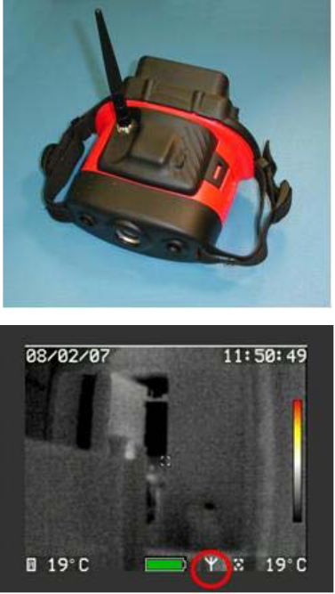
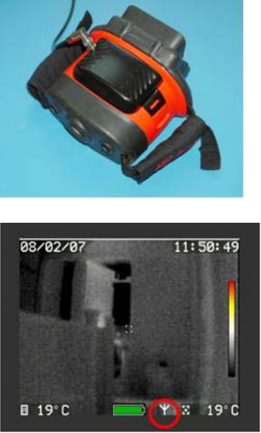
Fit the transmitter unit to the
camera as shown below and click
into place.
Switch on the camera with the red
button as normal and a picture will
be seen on the display.
To commence transmitting video, a
long push on the right-hand button
is required.
When the camera is sending video
the ‘transmit’ icon is shown on the
camera, circled in red on the image
opposite.
A further long push will turn the
transmission off. Transmission also
ceases when the battery is nearly
empty to extend the final few
minutes of run time.
When the video output is being sent out, any suitable device can connect and view the video. The
default stream address for the video source is rtsp://10.133.1.20:554/tic04
The IP address of the stream can be changed if required for an advanced installation as described
in the advanced section of this guide.
The default setting for the camera is that it is not sending output video as this conserves power
when in normal battery powered use. It is possible to set the camera to always turn on with output
video working by using the customer software or to control this remotely, see FAQ 1
Note: It is recommended that before each BA team enters the fire, the camera be fitted with a
fully charged rechargeable battery.
Disposal of batteries should be in line with local procedures and they should be
segregated from domestic waste. Alternatively, the batteries may be returned to e2v
technologies for safe disposal.
The battery pack will self-discharge at approximately 2% per day. Battery packs that have been
stored off-charge for two weeks will run a camera for at least two hours. It is recommended that
the rechargeable batteries are placed into storage fully charged and are routinely recharged so as
to be ready for use and to maintain performance. Shelf life is maximised by storage between 10
°C and 25 °C (50 °F and 77 °F). Battery packs that become fully exhausted in storage may suffer
irreversible damage.
©e2v technologies (uk) limited 2010 107553 09 Aug 2010 DAS762156AA (UK) Version 11, page 7
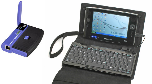
SECTION 3 - Argus®4 Receiver Station P7030RRS
This accessory allows reception and viewing of an Argus®4 camera transmitting video over Wi-Fi.
The Receiver Station accessory consists of the following items:
• Wireless network adaptor DAS762153AA
• Portable Computer DAS762155AA
• Software CD DAS762581AA
• User Guide (this booklet) DAS762156AA
• User Guides, warranties and software for the Computer and Access Point
The receiver station consists of a wireless network adaptor and a portable computer terminal
connected by USB. A 1.5 m USB lead is supplied with the network adaptor to allow the adaptor to
be placed in a more suitable receiving location.
The portable computer is loaded with appropriate software and is set up to work with a camera in
standard configuration. It may be used without the keyboard as it features a touch-screen.
Note that the exact equipment supplied may vary from these pictures due to product evolution in
the IT market.
INSTALLATION
Secure the wireless network adaptor in a suitable position. If it is to be used as a walk-about hand-
held, this will generally be to the computer or computer binder. For a fixed installation, the location
should be considered carefully to obtain the best reception. For example, in a vehicle, it would be
better on the windscreen or dashboard away from the metal bodywork. If required, USB extension
cables can be obtained from many retail outlets.
Raise the antenna and connect the USB lead to the portable computer.
©e2v technologies (uk) limited 2010 107553 09 Aug 2010 DAS762156AA (UK) Version 11, page 8
INSTRUCTIONS FOR USE
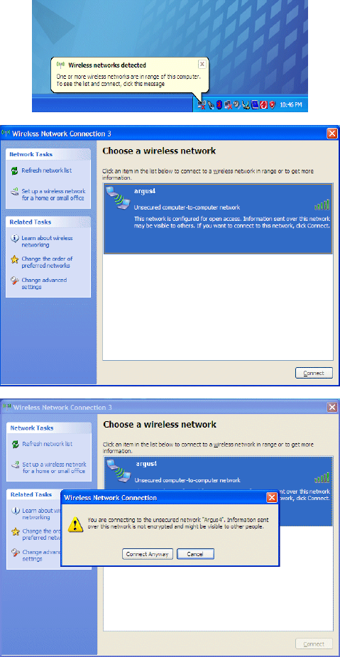
Switch on the computer and ensure that the camera is transmitting.
The network adaptor will
be recognised by the
computer and may
connect immediately to
the camera.
If the camera is not
connected automatically,
or the wrong camera or
network is connected,
view the ‘network monitor’
window by clicking the
icon and refresh when the
camera is switched on
and transmitting.
When a camera is
transmitting within range
this will show a potential
wireless network ‘argus 4’
Select and connect to the
desired camera
transmissions.
Ignore the warning
regarding the unsecured
connection and ‘Connect
Anyway’.
©e2v technologies (uk) limited 2010 107553 09 Aug 2010 DAS762156AA (UK) Version 11, page 9
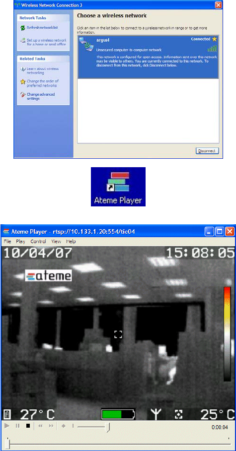
The screen opposite
confirms that a connection
has been established.
Click ‘Disconnect’ when it
is desired to end the
connection.
Disconnection will also
occur automatically if the
transmitter is turned off or
goes out of range.
Reconnection is normally
automatic when the
transmitter is back in
range.
When a connection is
established run the Ateme
Player via the icon on the
Desktop.
Video will then appear in
the Ateme Player window
and start playing
automatically.
If no video appears then
study the frequently asked
questions to investigate
the problem further.
If the camera has a
different IP address to
10.133.1.20 see section 7
on how to configure the
Ateme player.
©e2v technologies (uk) limited 2010 107553 09 Aug 2010 DAS762156AA (UK) Version 11, page 10
SECTION 4 - Argus®4 Receiver Kit P7030RKT
The Argus®4 receiver kit is a USB wireless network adaptor that
allows the transmitted video from the camera to be viewed on a
PC/Laptop. The receiver kit is supplied with:
• Wireless network adaptor and 1.5 m USB lead
• Installation CD for the adaptor
• Software CD containing video player DAS762581AA
• User Guide (this booklet) DAS762156AA
• Manufacturer’s user guide and warranty
This accessory allows the receiving of the Argus®4 thermal image
transmitted over Wi-Fi. The user must have a suitable computer in
order to view camera output. This product is offered to be compatible
with the instructions and guidance given for the other video
accessories and the model selected has been tested with the
camera to ensure that the expected range performance is obtained.
Note that the exact equipment supplied may vary from these pictures due to product evolution in
the IT market.
INSTALLATION
These instructions show how to set up a simple camera to computer link. For more complex
arrangements see section 9 and the FAQ.
It is recommended that the system be set up on a desk and some familiarity is gained before
making a permanent installation and using operationally.
The first step is to install the network adaptor on the PC/laptop/tablet PC and configure the
resultant connection set up to work in ad-hoc mode. For computers using Windows XP (SP2+)
and Vista operating systems, wireless networking is supported directly and this is the
recommended route and is shown below. For earlier versions (e.g. Win2000), the full device
software will need to be installed by following the installation instructions given for the Network
Adaptor.
The installation procedure may require administration rights on the computer used, depending
upon the individual policies applied to it.
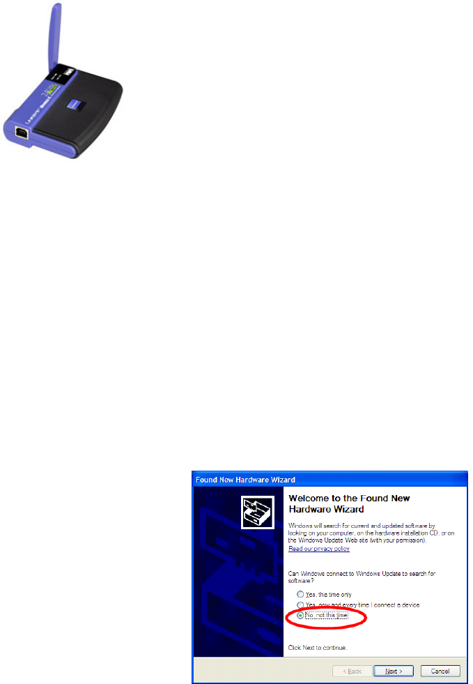
Plug the adaptor into the
chosen PC/laptop and the
adaptor will be detected as
new hardware.
Do not choose to use
Windows Update
©e2v technologies (uk) limited 2010 107553 09 Aug 2010 DAS762156AA (UK) Version 11, page 11
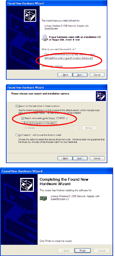
Direct the hardware wizard
to search the Wireless
adaptor CD for files.
Insert the network adaptor
CD into the CD drive of the
computer.
Agree to the installation.
Click ‘Finish’ to close the
wizard.
Do not agree to the wireless
connection at this point.
The hardware is now installed. The computer should now be adjusted with the network settings.
©e2v technologies (uk) limited 2010 107553 09 Aug 2010 DAS762156AA (UK) Version 11, page 12
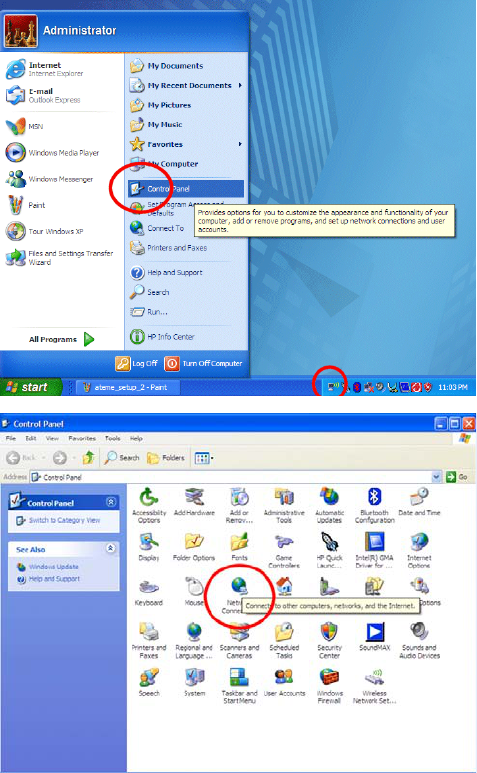
Open the ‘Network connections’
of the computer either from:
The system tray icon
Or
Start/Control Panel/Network
Connections
Or
Start/Settings/Network
Connections
©e2v technologies (uk) limited 2010 107553 09 Aug 2010 DAS762156AA (UK) Version 11, page 13
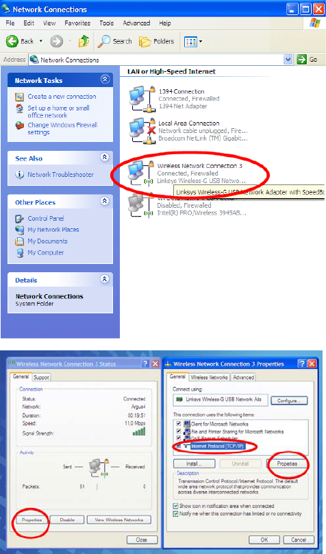
Pick the new wireless connection.
Which other connections are
present will depend upon the
computer specification.
In the example shown opposite,
there is a firewall port, a wired
network socket and also an
internal wireless network port.
Select properties and the TCP/IP
properties.
©e2v technologies (uk) limited 2010 107553 09 Aug 2010 DAS762156AA (UK) Version 11, page 14
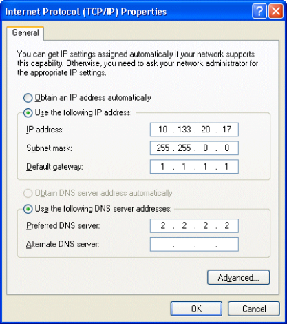
On the General tab click on “Use
the following IP Address”.
To ensure that a simple system
will avoid address clashes,
generate the computer address
using the method below.
Use the transmitter serial number
as the last two numbers in the
address.
e.g. for transmitter serial number
20.017, use 10.133.20.17 as the
computer address.
Enter the IP address selected for
the computer in the IP address
boxes, 10.133.20.17 in this
example.
Click in the Subnet mask box and
enter 255.255.0.0.
Enter 1.1.1.1 as the Default
gateway and enter 2.2.2.2 as the
preferred DNS server. These are
dummy values for this simple
connection.
The window should now be
populated as shown opposite.
Then click OK, followed by OK
again.
See FAQ 23 for more detail on
the IP address structure.
Secure the wireless network adaptor in a suitable position for day-to-day use. If it is to be used as
a walk-about hand-held, this will generally be to the computer, while for a fixed installation the
location should be considered carefully to obtain the best reception. For example, in a vehicle, it
would be better on the windscreen or dashboard away from the metal bodywork. If required, USB
extension cables can be obtained from many retail outlets.
This completes the Receiver Kit installation.
A suitable player should be installed at this point if it is not already on the chosen PC/laptop. The
Ateme Player supplied on the CD is recommended and the configuration of this player is covered
in section 8.
INSTRUCTIONS FOR USE
Day-to-day operation is now similar to the receiver station described in section 2.
©e2v technologies (uk) limited 2010 107553 09 Aug 2010 DAS762156AA (UK) Version 11, page 15
USE WITH ACCESS POINT SOFTWARE
As noted above when used with Win2000, and optionally with newer operating systems, the
wireless adaptor can be run using the manufacturers’ own software. Operation is essentially
similar in that the camera transmitter is detected in a survey screen and a connection is then made
to it.
The installation will be described in the documentation included with the access point.
An example of using Linksys software with a Linksys access point is shown below.
In some cases manufacturer software has been noted as more likely to attempt connection to
similar devices on a different network. It is therefore recommended to use the built-in Windows
software if possible.
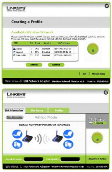
Run the survey to see the available
networks either from a shortcut
provided by the software or from a
system tray icon.
In the screen shown opposite argus4
is shown as one of the networks
available.
Select the Argus4 network and press
connect.
The wireless network adaptor will now
connect to the Argus4 network and
camera video is now available to the
player.
Once connected, the following screen
will appear showing connection
information.
©e2v technologies (uk) limited 2010 107553 09 Aug 2010 DAS762156AA (UK) Version 11, page 16
SECTION 5 - Argus®4 External Power and Video Adaptor
P7030EPVA
This accessory allows an Argus®4 camera to be powered from an external DC power source and
for the video from it to be viewed on a computer over a wired network connection, or on a video
monitor using a BNC lead.
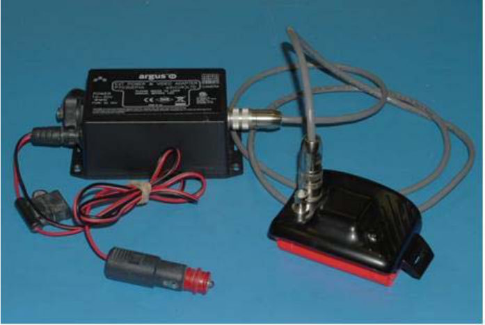
The External Power & Video Adaptor consists of the following items:
EPVA Battery Replacement Unit DAS761758AA
EPVA Cable DAS762180AA
EPVA Junction Box DAS762179AA
Software CD DAS762581AA
User Guide (this booklet) DAS762156AA
Description
The battery replacement unit plugs into the camera in place of the normal battery is connected to
the junction box via a rugged cable. The junction box has standard power and network
connections allowing the user connections to be placed in a more convenient location.
Power input range is 10 – 30 V, allowing use directly from both 12 V and 24 V vehicle supplies.
The connector supplied is a centre-positive vehicle accessory plug of the ‘cigarette lighter’ type.
Power may also be obtained from batteries or a suitable mains powered DC supply by feeding 10
to 30V into the unit via this lead. The camera will turn on whenever power is applied; the camera
power switch does not need to be used.
A 1.7 m (5 foot) length of rugged cable is provided to connect to between the camera and the
junction box.
The analogue video output socket is on the Battery Replacement Unit and is a 75 Ω BNC
connector. Analogue video will only be available when coupled to a suitably equipped camera, it is
not present as standard on all cameras.
©e2v technologies (uk) limited 2010 107553 09 Aug 2010 DAS762156AA (UK) Version 11, page 17
INSTALLATION
The EPVA requires a DC power source of between 10 and 30 V DC. A vehicle accessory plug is
provided (cigarette lighter), or this may be removed for direct connections to be made. Do not
connect directly to a mains voltage supply. The supply should be capable of supplying up to 10 W
(1 A at 10 V or 300 mA at 30 V). Reverse polarity protection is provided in the EPVA. The circuit
protection against reverse polarity and vehicle transients is inside the junction box and direct
connection from the cable or into the Battery Replacement Unit should not be attempted.
Note the limitation of use on page 2. The EPVA must not be used as a driver vision device for
example.
Analogue video will only be available when coupled to a suitably equipped camera, it is not
present as standard on all cameras.
Models P7030, P7030-LITE, P7009, P7130, P7225/D and P7250/D do not have analogue video
output capability.
Model P7030-LITE does not have any video output facility.
If in doubt please contact your distributor or e2v for advice on use with the cameras that you own.
Mount a camera as required. A standard tripod thread is fitted in the base of an Argus®4 for this
purpose. There is also a mounting bracket accessory available as P7030MB.
Connection to the camera is by fitting the Battery Replacement Unit in place of the standard
battery on the camera. Use the 1.7 m lead to place the junction box in a more convenient or
protected location.
The junction box network connector is a Woodhead RJ-Lnxx rugged industrial network socket
allowing the use of industrial or standard network leads. The socket has been wired with a network
crossover inside the unit. A standard network lead will allow connection directly to a computer,
while most routers will automatically sense polarity and still connect correctly. Full contact area
sealing is only maintained with the use of the matching RJ-Lnxx plug.
Where the EPVA is used solely to power a camera or for analogue output, the sealing cap should
be secured in place on the network socket.
The analogue video output is direct from the Battery Replacement Unit and should use a 75 Ω
cable suitable for the location (e.g. high temperature or low smoke).
A computer is required to receive digital video and the configuration options for this are covered in
section 9. It is recommended that a computer with a second network device is used for connection
to cameras, either as a point-to-point or small router based network, separate to other corporate
and internet connectivity.
Analogue video is in NTSC 60 Hz format and can be displayed on a standard video monitor or
through most modern TV sets by using video inputs. The connector on a television or video
recorder is usually an RCA phono socket and coloured yellow and labelled ‘AV in’ or similar. The
camera does not connect directly to the antenna socket.
Both the Junction Box and Battery Replacement Unit are sealed. There are no user serviceable
parts inside.
The default setting is for the camera not to send output video when turned on in order to conserve
power when in normal battery powered use. It may be found more convenient to set the camera
always to turn on with output video sending through setting this mode with the customer software.
With the automatic switch on this will give a fully automatic camera feed from just switching the
power to the EPVA.
Warning
This is a Class A product. In a domestic or office environment this product may cause radio
interference in which case the user may be required to take adequate measures.
©e2v technologies (uk) limited 2010 107553 09 Aug 2010 DAS762156AA (UK) Version 11, page 18
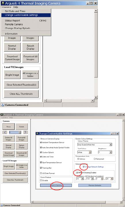
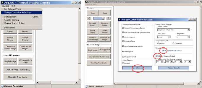
To change the camera so that it
sends output video from switch-on,
connect the camera to a PC that
has the customer software installed
on it using the USB lead supplied
with the camera. Run the software
and select Camera – change
customisable settings.
Tick the box ‘Change Network
Settings’ and tick the box ‘MPEG4
Streaming Enabled’. Click ‘Save to
Camera’.
©e2v technologies (uk) limited 2010 107553 09 Aug 2010 DAS762156AA (UK) Version 11, page 19
INSTRUCTIONS FOR USE
Powering a Camera
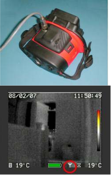
Fit the battery substitute unit to the
camera as shown below and click into
place. Plug the cable into to the junction
box and camera.
Plug the DC power lead into a suitable
outlet, and switch on if necessary. The
camera will now turn on and a picture will
be seen on the display. The camera is
controlled by the power applied to it; the
power switch does not control the camera
when it is being powered externally.
Sending Video from a Camera
Video output from the camera must be
started either by a long push on the right-
hand button or remotely via the customer
software. Alternatively, the camera may
be set always to turn on with output video
sending as described in FAQ 1. When the
camera is sending video the ‘transmit’
icon is shown on the camera, circled in
red on the image.
©e2v technologies (uk) limited 2010 107553 09 Aug 2010 DAS762156AA (UK) Version 11, page 20
SECTION 6 – Analogue Output Battery Pack P7030AVBP
This accessory allows a suitable Argus®4 camera to provide an analogue video output signal over
a BNC lead to a suitable display device. This is incorporated in a battery pack that provides power
for the camera. Connection to the camera is by replacing the standard battery with the unit
supplied. There are no user serviceable parts inside.
Analogue video will only be available when coupled to a suitably equipped camera, it is not
present as standard on all cameras.
Models P7030, P7030-LITE, P7009, P7130, P7225/D and P7250/D do not have analogue video
output capability.
Model P7030-LITE does not have any video output facility.
If in doubt please contact your distributor or e2v for advice on use with the cameras that you own.
INSTRUCTIONS FOR USE
The Analogue Output Battery Pack is similar to a standard battery, and should be charged with the
standard camera charger accessories; the mains charger supplied with the camera
(P7030BC+CS) or the vehicle charger (P7030TBC). The battery bar display gives the same
camera display of the battery state as a standard battery, although run time is slightly reduced
when sending video.
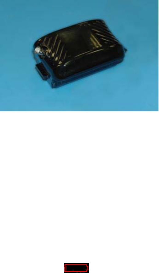
When the battery reaches low, as shown below, the video output is automatically turned off to
ensure that final runtime beyond the low battery warning is maintained.
To maintain the accuracy of the battery charge indicator, e2v recommends that batteries be
occasionally fully discharged in a camera before charging.
©e2v technologies (uk) limited 2010 107553 09 Aug 2010 DAS762156AA (UK) Version 11, page 21
Connection to the camera is by fitting the
Analogue output Battery Pack in place of
the standard battery on the camera.
Video output from the camera must be
started either by a long push on the right-
hand button or remotely via the customer
software. Alternatively, the camera may
be set always to turn on with output video
sending as described in FAQ 1. When the
camera is sending video the ‘transmit’
icon is shown on the camera, circled in
red on the image.
The analogue video signal is in NTSC
60Hz format. This may be displayed on a
video monitor or, by using video inputs,
on a television or via a video recorder, or
into a computer using a TV card. The
connector on such devices is usually an
RCA phono socket and coloured yellow
and labelled ‘AV in’ or similar. The
camera does not connect to the antenna
socket.
Note: It is recommended that before each BA team enters the fire, the camera be fitted with a
fully charged rechargeable battery.
Disposal of batteries should be in line with local procedures and they should be
segregated from domestic waste.
The battery pack will self-discharge at approximately 2% per day. Battery packs that have been
stored off-charge for two weeks will run a camera for at least two hours. It is recommended that
the rechargeable batteries are placed into storage fully charged and are routinely recharged so as
to be ready for use and to maintain performance. Shelf life is maximised by storage between 10
°C and 25 °C (50 °F and 77 °F). Battery packs that become fully exhausted in storage may suffer
irreversible damage.
©e2v technologies (uk) limited 2010 107553 09 Aug 2010 DAS762156AA (UK) Version 11, page 22
SECTION 7 – Video Capture Battery Pack P7030VC
This accessory allows recording of video from any Argus®4 camera, and the downloading of it to a
PC for viewing later. This is incorporated in a battery pack that provides power for the recording
device and the camera.
The P7030VC Video Capture Battery Pack consists of the following items:
Video Capture Battery pack DAS766270AA
Software CD DAS762581AA
User Guide (this booklet) DAS762156AA
Connection to the camera is by replacing the standard battery with the unit supplied. There are no
user serviceable parts inside.
INSTRUCTIONS FOR USE
The video capture battery pack contains a standard battery and may be charged with the standard
camera charger accessories, the mains charger supplied with the camera (P7030BC+CS) and the
vehicle charger (P7030TBC). It also contains circuitry to give the same camera display of the
battery state as a standard battery, although run time is reduced, giving a typical 3 hours in
ambient temperatures whether recording or not.
When the battery reaches low, as shown below, the recording is automatically stopped to ensure
that final runtime beyond the low battery warning is maintained and the file is saved correctly.
To maintain the accuracy of the battery charge indicator, e2v recommends that batteries be
occasionally fully discharged in a camera before charging.
©e2v technologies (uk) limited 2010 107553 09 Aug 2010 DAS762156AA (UK) Version 11, page 23
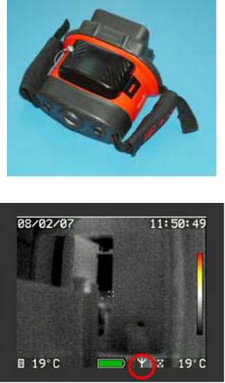
Fit the video capture battery pack to the
camera as shown right and click into place.
Switch on the camera with the red button as
normal and a picture will be seen on the
display.
To initialise the video recording, a long push
on the right-hand button is required. The
transmit icon will appear on the viewing screen
as circled on the image below right.
Once the initialisation process has been
completed, after approx 15 seconds, the video
capture battery pack will start to record the
video.
A further long push on the right-hand button
will stop the recording of the video. The
transmit icon will disappear. The video capture
battery pack will now finish saving the file to its
internal memory and shut down the video
recording device. This process will take
approx 30 seconds and the camera will not
turn off during this time.
Do not remove the battery or turn the camera
off during the saving process as this will
corrupt the recorded file.
Video recording will automatically stop when
the battery capacity is nearly empty. This
ensures that the recorded file is saved
correctly and enables the user to have
approximately 10 minutes of camera use
before the camera loses power.
The P7030-LITE model does not have a video output facility, and therefore cannot be used to
capture video
The default setting for the camera is that it is not saving output video. It is possible to set the
camera so that when it is turned on it will commence recording immediately and without user input.
See FAQ 1 for instructions on how to do this with the customer software.
Note: It is recommended that before each BA team enters the fire, the camera be fitted with a
fully charged rechargeable battery.
Disposal of batteries should be in line with local procedures and they should be
segregated from domestic waste.
The battery pack will self-discharge at approximately 2% per day. Battery packs that have been
stored off-charge for two weeks will run a camera for at least two hours. It is recommended that
the rechargeable batteries are placed into storage fully charged and are routinely recharged so as
to be ready for use and to maintain performance. Shelf life is maximised by storage between 10
°C and 25 °C (50 °F and 77 °F). Battery packs that become fully exhausted in storage may suffer
irreversible damage.
©e2v technologies (uk) limited 2010 107553 09 Aug 2010 DAS762156AA (UK) Version 11, page 24
INSTRUCTIONS FOR PLAYBACK
The files can be played back using the Ateme Player supplied on the enclosed CD; see section 8
of the manual for installation instructions. The files can also be played back on other media
players (including Windows Media player) if the correct CODEC for MPEG-4 is present. The
CODEC for other media players can be found on the internet.
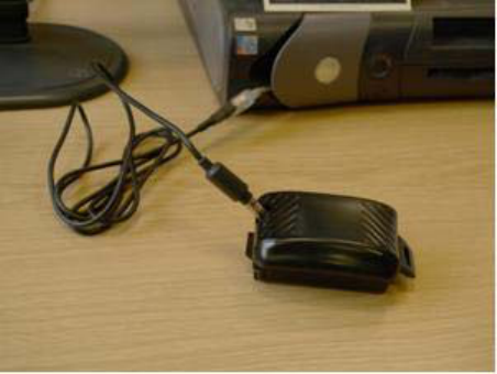
To play back the saved video, connect the video capture battery pack to a Laptop/PC using the
USB Lead supplied with your Argus® camera.
After a short while, the video battery pack should automatically appear on the Laptop/PC as a
removable memory device similar to a standard memory stick. The saved video files can now be
played directly from the video capture battery pack or copied to the laptop/PC and viewed from the
stored location.
Note: The videos stored on the video capture battery packs are a maximum 30 minutes long
to keep the size of the files small. When recording these files, there will be no indication
to the user that this has occurred. However, any video larger than 30 minutes will be
split and would have to be viewed separately. The video filenames will be of the form
VSA#####.mp4.
Once the video files have been saved to a Laptop/PC it is recommended that the video files on the
video capture battery pack are deleted to ensure full usability of the device.
©e2v technologies (uk) limited 2010 107553 09 Aug 2010 DAS762156AA (UK) Version 11, page 25
SECTION 8 – LRT System
The Long Range Telemetry (LRT) video transmission system is an advanced premium system
offering exceptional range as well as full quality pictures and higher levels of security than the Wi-
Fi system.
This system allows an Argus®4 camera to transmit video over a digital video link to the receiver
and to be viewed on the receiver screen.
The transmitter is incorporated in a battery pack that provides power for both transmitter and
camera. Connection to the camera is by replacing the standard battery with the unit supplied.
There are no user serviceable parts inside.
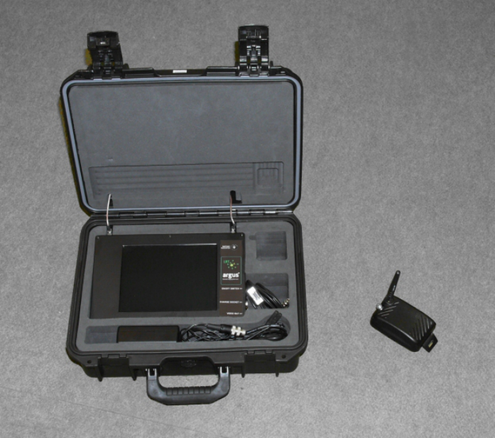
The receiver may be purchased as a separate device (DTX1400 or DTX 2400) or in a Remote
Receiver Station (DRRS1400 or DRRS2400) in a hard carry case.
This accessory requires a camera with analogue video output. Analogue video is not present as
standard on all cameras.
Models P7030, P7030-LITE, P7009, P7130, P7225/D and P7250/D do not have analogue video
output capability.
Model P7030-LITE does not have any video output facility.
If in doubt please contact your distributor or e2v for advice on use with the cameras that you own
©e2v technologies (uk) limited 2010 107553 09 Aug 2010 DAS762156AA (UK) Version 11, page 26
INSTALLATION
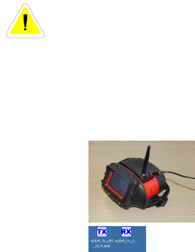
To meet legal requirements, the LRT transmitter is shipped with the RF output turned off, and the
transmitter set to a ‘nominal’ frequency.
THE EQUIPMENT WILL NOT OPERATE AS SHIPPED
Before operating the device, it is the user’s responsibility to determine
an acceptable frequency and power level and obtain any necessary
licences from the appropriate local authorities to operate the
transmitter.
The data required for a typical licensing submission is given in the
specification section.
The chargers for the LRT system are not certified for use whilst the
receiver is switched on.
The frequency, bandwidth and power settings should only be changed by competent persons who
have a thorough understanding of the legal implications of the local license conditions for radio
transmission.
Transmission with improper settings may be an offence in your location.
The permitted frequency and power should then be set in the transmitter and the transmitter RF
enabled. This is performed using the configuration software provided on the CD. Other factory
parameters for the transmitter should not be changed. However, if the transmitter is to be used
with a pre-installed receiver such as a command vehicle, the transmitter and receiver must be set
to matching configurations. A mismatch between transmitter and receiver may cause the system
to cease functioning. Consult e2v or the command system provider if setting up a system involving
a command vehicle where that system needs priority or to implement higher security settings.
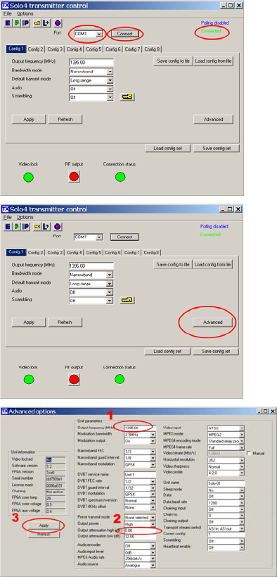
Plug the transmitter into a camera and
turn on. Charge if necessary
beforehand.
Set the camera to transmit.
Connect the serial lead supplied from
the transmitter to the PC serial port or a
serial port adaptor.
Copy the TX and RX setup programme
from the CD to your PC.
Run the TX setup programme.
©e2v technologies (uk) limited 2010 107553 09 Aug 2010 DAS762156AA (UK) Version 11, page 27
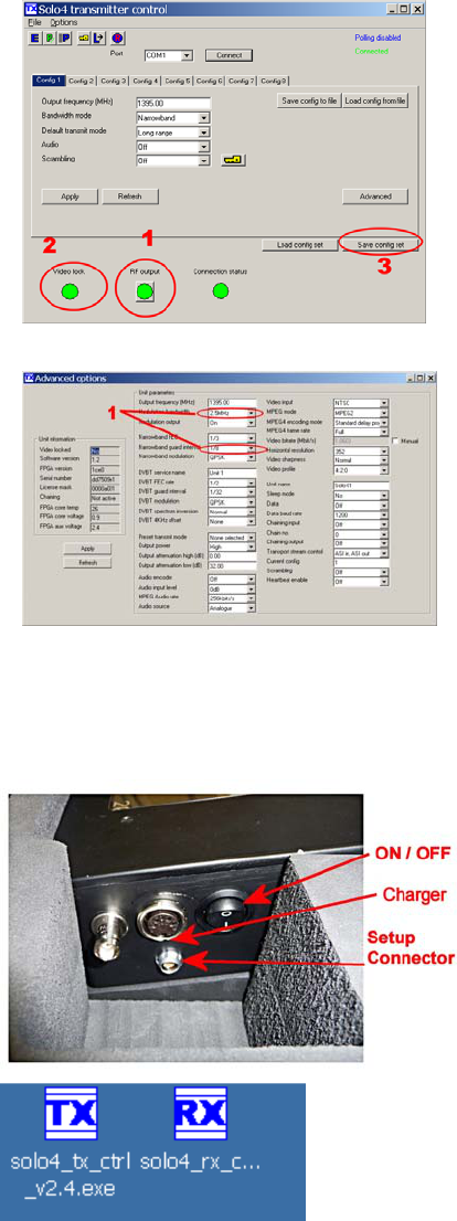
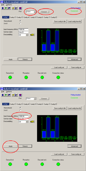
Select the COM port where the
transmitter is connected and click on
Connect.
The word “Connected” should now turn
green, and the Connection status
indicator show green.
The boxes will fill with the current
settings.
Now click ‘Advanced’
Now set the frequency and adjust the
power level if necessary to meet the
license conditions granted to you.
1. Enter the output frequency in MHz.
This example shows a DTX1400 set to
a frequency of 1395 MHz.
The frequency entered is the centre
frequency. This must be more than 2
MHz away from any frequency band
limits specified in the licence.
2. Adjust the power level if required.
The transmitter is 100 mW output when
set to 0 dB attenuation.
For 25 mW set 6 dB attenuation.
For 10 mW set 10 dB attenuation.
3. Click ‘Apply’.
Allow for the antenna gain if setting for
a maximum permitted e.i.r.p. level.
©e2v technologies (uk) limited 2010 107553 09 Aug 2010 DAS762156AA (UK) Version 11, page 28
Check that the correct frequency is now
shown
1. Click the RF output button to switch
on the radio.
Note the Video lock is green; this
means that the camera analogue video
is being detected by the transmitter.
If this is red, check that the camera has
analogue video output.
3. It is possible to save the
configuration to make future set-up
easier. This is especially the case if
other adjustments have to be made, for
instance to suit a command vehicle set-
up.
If making advanced adjustments, note
that these two settings are not
automatically detected at the receiver. If
changed, these must also be manually
input on the receiver.
The receiver also requires to be set to the transmitter frequency using the configuration software
provided on the CD. Other factory parameters for the receiver should be suitable, but if
transmission parameters are adjusted in the transmitter, the receiver will need to be set to match.
The receiver unit should be charged
before use.
Switch the receiver on.
Connect the serial lead supplied
from the setup connector to the PC
Run the RX setup programme
copied from the CD
©e2v technologies (uk) limited 2010 107553 09 Aug 2010 DAS762156AA (UK) Version 11, page 29
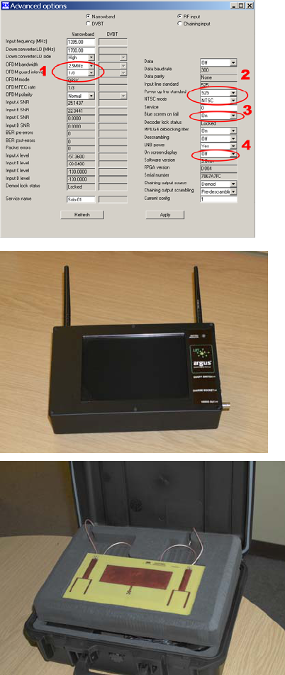
Select the COM port where the
transmitter is connected and click on
Connect.
The word “Connected” should now
turn green.
Enter the frequency of the
transmitter.
Click ‘Apply’.
The screenshot shows a typical
display when a camera is
transmitting nearby. The signal
strength and quality from each
antenna are shown.
The green indicators show that video
is being received and decoded
correctly.
It is also possible to set up more
than one receive frequency if the
location permits more than one
transmit frequency this could allow
two cameras at once. This is set up
in the separate config tabs.
The configuration can be saved to a
file for easy application to further
receiver units.
©e2v technologies (uk) limited 2010 107553 09 Aug 2010 DAS762156AA (UK) Version 11, page 30
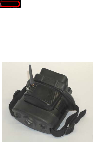
Advanced adjustments should not
normally be needed, but the
following should be noted:
1. These parameters are not
automatically detected in the
transmission and have to be set for
transmitter and receiver, and must
match or the system will not work.
2. Always set for 525 NTSC, this is
the camera output
3. If preferred, set the screen to go
black when no signal is present.
4. The receiver can be set to display
signal strength. This may be of use
in setting up a fixed location such as
a training centre or observation.
The receiver station is supplied with
the two omnidirectional antennae in
the lid connected. The receiver
station may be removed from the
case and the two small rubber
aerials used, in the manner of the
simple receiver unit.
A performance increase may be
obtained if the transmitter is in a
known direction. The central antenna
in the lid is directional, giving
approximately 4 times the signal.
To use this mode, drop the foam
from the lid and disconnect one of
the outer antennas. Reconnect the
lead to the centre connection with
the spanner provided.
There is no need to tighten to an
extreme, over-tightening may cause
damage.
©e2v technologies (uk) limited 2010 107553 09 Aug 2010 DAS762156AA (UK) Version 11, page 31
INSTRUCTIONS FOR USE
Camera / Transmitter
The transmitter battery pack contains a standard battery and may be charged with the standard
camera charger accessories, the mains charger supplied with the camera (P7030BC+CS) and the
vehicle charger (P7030TBC). It contains circuitry to give the same camera display of the battery
state as a standard battery, although run time is reduced when transmitting, giving a typical 2
hours in ambient temperatures.
When the battery reaches low, as shown below, the transmitter is automatically turned off to
ensure that final runtime beyond the low battery warning is maintained.
To maintain the accuracy of the battery charge indicator, e2v recommends that batteries be
occasionally fully discharged in a camera before charging.
Note: A LRT transmitter battery cannot be charged attached to the camera in the vehicle storage
mount.
It should also be noted that the battery charger might indicate an error due to high battery
temperature following extended use with the transmitter running. Allow the battery to cool before
charging.
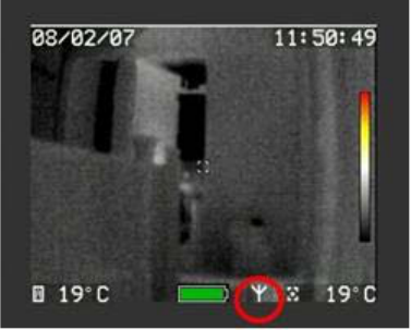
Fit the transmitter unit to the
camera as shown below and click
into place.
Switch on the camera with the red
button as normal and a picture will
be seen on the display.
To commence transmitting video, a
long push on the right-hand button
is required.
©e2v technologies (uk) limited 2010 107553 09 Aug 2010 DAS762156AA (UK) Version 11, page 32
When the camera is sending video
the ‘transmit’ icon is shown on the
camera, circled in red on the image
opposite.
A further long push will turn the
transmission off. Transmission also
ceases when the battery is nearly
empty to extend the final few
minutes of run time.
The default setting for the camera is that it is not sending output video as this conserves power
when in normal battery powered use. It is possible to set the camera to always turn on with output
video working by using the customer software or to control this remotely, see FAQ 1.
Note: It is recommended that before each BA team enters the fire, the camera be fitted with a
fully charged rechargeable battery.
Disposal of batteries should be in line with local procedures and they should be
segregated from domestic waste.
The battery pack will self-discharge at approximately 2% per day. Battery packs that have been
stored off-charge for two weeks will run a camera for at least two hours. It is recommended that
the rechargeable batteries are placed into storage fully charged and are routinely recharged so as
to be ready for use and to maintain performance. Shelf life is maximised by storage between 10
°C and 25 °C (50 °F and 77 °F).
Battery packs that become fully exhausted through extended storage may suffer irreversible
damage.
©e2v technologies (uk) limited 2010 107553 09 Aug 2010 DAS762156AA (UK) Version 11, page 33
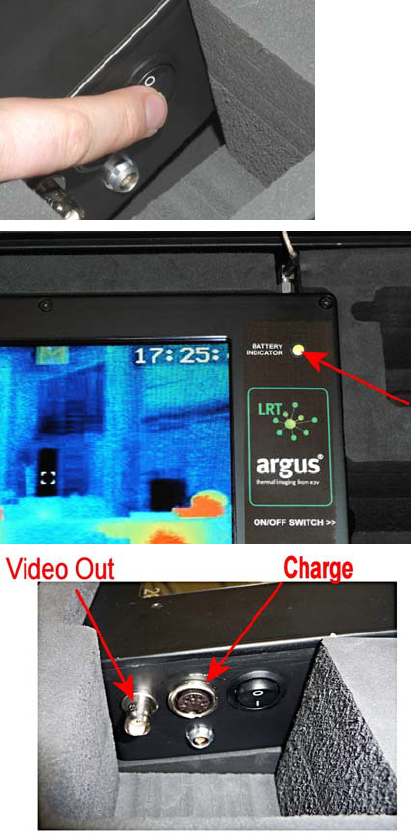
Receiver
The receiver contains a battery pack and is charged using the charger provided. Both AC and DC
versions are available.
Do not charge with the standard camera charger accessories.
Do not use this charger to charge camera batteries.
The receiver is switched on with this
switch on the side.
The state of charge is indicated by
the colour LED.
This is normally green, changing to
yellow when approximately 1 hour
remains and then changing to red
approximately 20 minutes before the
battery is exhausted.
The receiver is charged through this
socket. Only charge using the
charger supplied.
The unit must not be switched on
whilst being charged.
The video socket allows connection
of standard video accessories such
as recorders and monitors.
See FAQ 13 and 14 for more details.
©e2v technologies (uk) limited 2010 107553 09 Aug 2010 DAS762156AA (UK) Version 11, page 34
SECTION 9 - Ateme Player Installation
Ateme Player Installation
The Ateme player software is supplied to allow viewing of the camera digital video data stream on
a PC. The software is pre-installed on the P7030RRS. Installation is only necessary on user-
supplied PCs or where a different configuration is desired.
Run setup.exe from the Ateme folder on the CD supplied.
Follow the instructions in the readme.txt file to register the software to remove the logo from the
player.
Ateme Player First Use and Set-Up
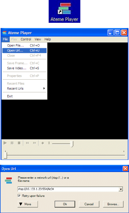
Once the installation has been
successfully completed,
double-click on the Ateme icon
and run the player.
Run Ateme Player either via
the icon on the Desktop or
from the Start menu.
Select ‘Open URL’ from the
File drop down menu and enter
rtsp://10.133.1.20:554/tic04
into the dialogue box.
Ensure that the “Retry upon
failure” box is ticked and then
click OK.
The URL given is for a camera
with the default settings. If the
camera IP address has been
changed for any reason, enter
the actual camera address
instead of 10.133.1.20
To use the player to play back
a recorded file from the video
capture battery pack, simply
choose ‘Open File...’ and
select the file required.
©e2v technologies (uk) limited 2010 107553 09 Aug 2010 DAS762156AA (UK) Version 11, page 35
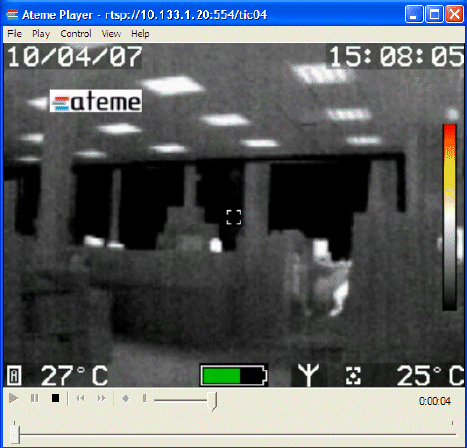
If a camera is connected by
wireless or through a wired
connection, video will then
appear in the Ateme Player
window and start playing
automatically.
If no video appears, then study
the FAQ section to investigate
the problem further.
The desktop icon may be modified to run a given camera address with a single click. Several icons
may be created, allowing one for each camera, for example.
1. Right-click the short cut for the ATEME player and select properties.
2. The TARGET box should contain a string like "C:\Program Files\ATEME\Ateme Player\Ateme
Player.exe"
3. Append the following; rtsp://nnn.nnn.nnn.nnn:554/tic04 /fullscreen /retry to the string with an
appropriate camera IP address. There is a space between tic04 and /fullscreen and between that
and /retry
4. The complete string would be as follows:
"C:\Program Files\ATEME\Ateme Player\Ateme Player.exe" rtsp://10.133.1.20:554/tic04 /fullscreen
/retry
for a camera with the default IP address 10.133.1.20
5. Change the setting in the RUN box to maximized.
6. Click Apply followed by OK.
Omit ‘fullscreen’ and ‘maximized’ commands if desired.
©e2v technologies (uk) limited 2010 107553 09 Aug 2010 DAS762156AA (UK) Version 11, page 36
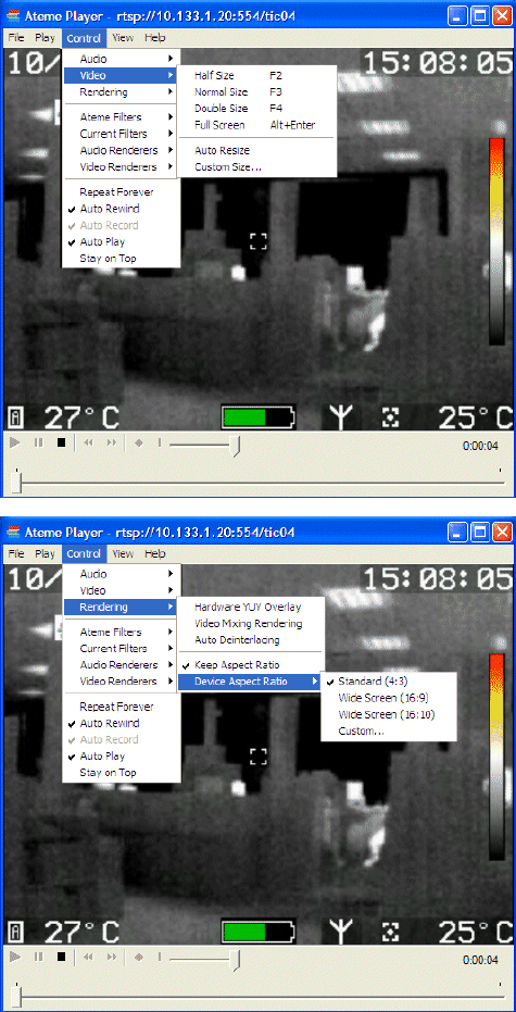
The Ateme player has several
preset video sizes that are
selected as shown opposite.
F4 (double size) and
ALT+ENTER (full screen) are
the most likely to be of use.
It is also possible to drag the
window to resize although this
is not recommended. It can
have unforeseen consequences
in creating image artefacts and
aspect ratio problems.
The following optimisations are
recommended for the Ateme
player:
The screen aspect ratio should
be fixed using the method
shown opposite.
In the ‘Keep Aspect Ratio’
options, tick ‘Standard (4:3)’.
©e2v technologies (uk) limited 2010 107553 09 Aug 2010 DAS762156AA (UK) Version 11, page 37
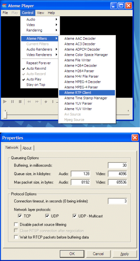
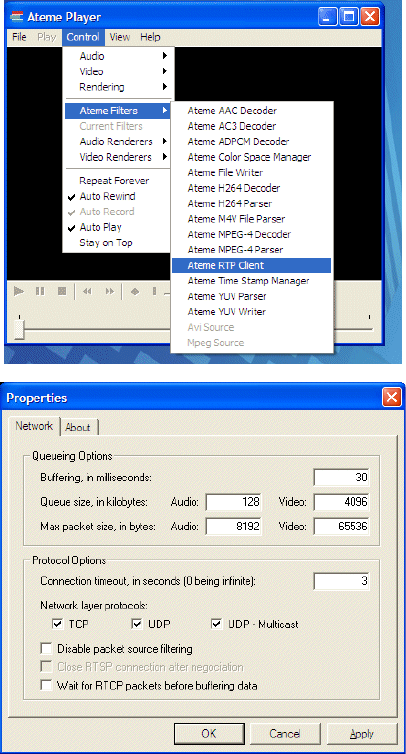
The delay between the camera
image and that displayed
should be reduced from the
default value.
Enter the “Control” drop-down
menu in Ateme Player and
select ‘Ateme Filters’ and then
‘RTP Client’.
The properties window will
then appear.
Set the “Buffering, in
milliseconds” value down from
the default of 3000 to a much
lower figure; it should be set to
30.
Note that a setting of 0 may be
found to be unsatisfactory.
Click ‘Apply’ and ‘OK’.
©e2v technologies (uk) limited 2010 107553 09 Aug 2010 DAS762156AA (UK) Version 11, page 38
SECTION 10 - Applications and Advanced Use
There are several connection methods available as detailed below, each more suited to certain
applications and configurations.
Connecting One Camera to One Computer (Point-to-Point - Wired)
This is applicable to the EPVA. A data connection is established directly between the camera and
the network device inside or attached to the computer.
The computer must have either a spare network socket or a USB to network adaptor. If the
computer is already networked, a second adaptor or card may be fitted instead of swapping wires
and settings.
A suitable streaming video player must also be installed on the computer. e2v have supplied a
player by Ateme on the CD, but other players are available. See FAQ 10 for a discussion of the
merits of the various alternative players such as Apple Quicktime and VLC.
To make a point-to-point connection, the computer must be set to the same network subnet as the
camera. By default, the camera is set to IP address 10.133.1.20, so the computer must be
assigned an IP address in the range 10.133.1.x. Typically, this would be 10.133.1.2. These
settings have been chosen to avoid any conflicts with the wireless system and should avoid most
other network systems in use.
Note that normally the IP address is set to ‘Obtain IP address automatically’ but this will not work,
as there is no automatic address allocation in point-to-point systems. If for any reason a specific
computer address is needed, change the camera address instead as detailed in FAQ 24.
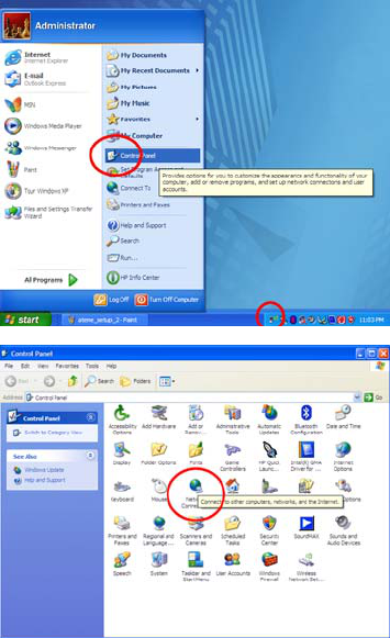
Open the network connections
window on the computer via:
The system tray icon
Or
Start/Control Panel/Network
Connections
Or
Start/Settings/Network
Connections
©e2v technologies (uk) limited 2010 107553 09 Aug 2010 DAS762156AA (UK) Version 11, page 39
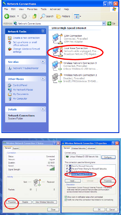
Select the network connection
where the camera is connected,
then navigate to the TCP/IP
properties window as shown
opposite.
©e2v technologies (uk) limited 2010 107553 09 Aug 2010 DAS762156AA (UK) Version 11, page 40
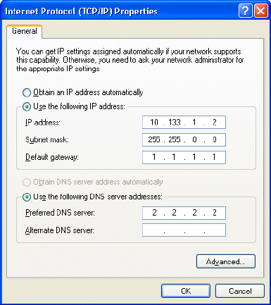
On the General tab, click on “Use
the following IP Address”.
Enter the IP address of the
computer as 10.133.1.2.
Click in the Subnet mask box,
and enter 255.255.0.0.
Enter 1.1.1.1 as the Default
gateway Enter 2.2.2.2 as the
preferred DNS server.
These are dummy values for this
simple connection.
The window should now be
populated as shown opposite.
Click OK, followed by OK again.
Connecting Cameras to a Wired Network and Router
In this configuration the router manages the network of cameras with EPVAs and computers,
reducing the PC configuration required. This allows other network functionality to be retained
through the router and is also how a camera would be added to a network that already exists.
Multiple cameras can be connected and the image(s) viewed can be selected by choosing the
desired IP address in the player software. The viewing computer may also be on a wireless link
from the router.
The detail of configuration depends primarily upon the selected router and is not within the scope
of e2v product support. The information below is general guidance to allow competent users to
operate a system in the locally networked configuration.
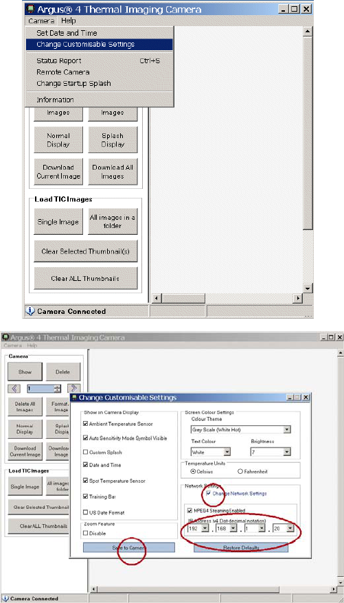
In this configuration the camera and the network settings of the router must match. It is normally
simplest to change the camera IP address to suit the address range of the router, which is typically
192.168.1.x but may vary between manufacturers and local settings. Additionally, make sure that
the address chosen for the camera is not in use by any other device on the network.
©e2v technologies (uk) limited 2010 107553 09 Aug 2010 DAS762156AA (UK) Version 11, page 41
Connect the camera to a
computer with the USB lead
and run the customer
software.
Select the ‘Change
Customisable Settings’ option.
Tick the ‘Change Network
settings’ box.
Enter the desired IP address.
Click ‘Save to Camera’.
The camera does not use automatically assigned DHCP IP addresses. It is recommended that the
address(es) used for cameras be denied to DHCP address allocation in the router set-up.
Further cameras can be connected as required, but each must be set to a unique IP address in
the range used by the router.
A system may also be configured with the router set to use the address range of the cameras
(10.133.xxx.xxx), but note that as all cameras are given the same address in the factory at least
one will require to be changed to implement a multiple camera configuration.
©e2v technologies (uk) limited 2010 107553 09 Aug 2010 DAS762156AA (UK) Version 11, page 42
Connecting to a Computer (Wireless – Point-to-Point)
This is the configuration described for the receiver accessories and is the simplest connection to a
camera through the Transmitter battery pack. With all cameras having the same IP address, one
transmitter can be swapped between several cameras without further set-up. However, ensure
that only one transmitter is in use at any one time. See also FAQ 19 and 20 for advice on using
more than one transmitter at a time.
When using with other computers and network adaptors, the configuration depends primarily upon
the selected devices and is not within the scope of e2v product support. The information below is
general guidance to allow competent users to operate a system in a point-to-point configuration.
The process will be similar to that described in section 4 for installing the P7030RKT.
The computer to be used as the receiver must either have a wireless network card fitted or be
connected to an external USB network adaptor or similar device. The receiving device chosen
should have an external antenna; integral antennae and those used in USB key-fob style network
adaptors will give very poor performance.
In all cases establishing a connection follows the same steps:
• The computer must be set for a direct network connection with a fixed IP address in the
correct range and suitable subnet masking.
• The camera must be switched on and transmitting.
• Use the PC network setup functions, whether Windows or proprietary to the network
adaptor, to perform a ‘network survey’ to find the ‘argus4’ wireless ‘network’ SSID.
• Connect to ‘argus 4’ as an ‘ad-hoc’ connection.
The camera video stream is then available to be played on the computer by playing/opening the
url rtsp://xxx.xxx.xxx.xxx:554/tic04 where xxx.xxx.xxx.xxx is the camera IP address. The
configuration of the Ateme player is covered in section 6.
It is vital that no clashes of IP addresses exist in the wireless environment, and to understand that
some of the devices present may not be under the users’ control. For this reason the address
range for the Argus®4 wireless accessories has been chosen to be different to the normal ranges
used by common private systems. To ensure that unique addresses are used within it a
numbering scheme of FAQ 23 is suggested whereby device addresses are derived from serial
numbers to avoid clashes between Argus®4 transmission systems. The exception to this is with
cameras. Cameras are all supplied with the same address (10.133.1.20) so that one receiver-
transmitter pair can be used with several cameras without adjustment. If more than one transmitter
is present the camera addresses must be changed as described in FAQ 24.

©e2v technologies (uk) limited 2010 107553 09 Aug 2010 DAS762156AA (UK) Version 11, page 43
Connecting to a Computer (Wireless – Networked)
This configuration enables several cameras to operate at once and a combination of wired and
wireless cameras to be operated together. Additionally the display computer may also be
positioned away from the receiver potentially doubling the range. A router offers some
performance benefits in managing the network in a busy wireless environment. It also allows wired
camera connections and may allow other networking functionality or internet access for example.
This configuration depends primarily upon the selected devices and is not within the scope of e2v
product support. The information below is general guidance to allow competent users to operate a
system in the wireless networked configuration.
The adjustment of these settings in the module is different across the various versions of module
firmware. Contact e2v for assistance. In some instances familiarity with TELNET access is
required as some versions of module do not have a web interface.
Use of a wireless router transfers control of the transmitter frequencies to the
router. Do not attempt this mode of operation unless certain that the system will
be legal at all times by using the correct router settings. The transmitter is under
100 mW 20 dBm effective output power.
Operation on channels 9 – 13 (above 2454 MHz) is not
permitted outdoors in France.
Check http://www.art-telecom.fr/ for more details.
Là où utilisé dehors, creuser des rigoles seulement 1 – 8
(2400 - 2454 MHz) peuvent être employés.
Visitez http://www.art-telecom.fr/ pour de plus amples détails.
There are two network devices present for each transmitting camera; the camera video output
itself and a transmitter control module in the transmitter battery pack. The configuration set for the
transmitter control module as shipped from e2v is for an ad-hoc (point to point) network using fixed
IP addressing.
The settings in the transmitter control module must be changed to work within a router controlled
‘infrastructure’ network. It is also recommended that DHCP address allocation be used for the
control module. Additionally the camera(s) and the router must be set to use a compatible IP
address range. Note particularly that cameras do not use DHCP address allocation. This includes
any wired cameras and other devices connected to the same router.
A static address may be set for the control module, but note that this does not set the camera
address.
Do not use an address that is the same as any camera, the router, the router DHCP range or any
other fixed IP device on the network.
All wireless devices must use the same ‘SSID’ as the router. The SSID is best chosen to reflect
the router or network identity itself and not ‘argus4’ to avoid confusion with any point-to-point links
in the vicinity.
If encryption or MAC address locking is employed as a security measure, this must also be set at
the transmitter control module and the camera MAC address must be permitted access to the
network.
©e2v technologies (uk) limited 2010 107553 09 Aug 2010 DAS762156AA (UK) Version 11, page 44
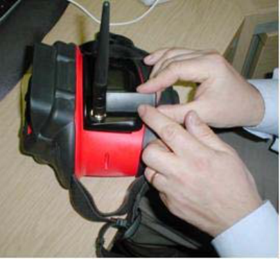
The transmitter control module can be reset to a known configuration by applying a magnet to the
module adjacent to the antenna as shown.
Hold the magnet in position for 30 seconds while the transmitter is turned on.
The reset state is:
• Connection Ad-Hoc
• Channel 1
• IP address 10.133.220.1
• DHCP No – fixed addresses
• SSID argus4
• Encryption Off
This should be changed to the desired setting as soon as possible to avoid the possibility of two
reset transmitters coming within range and disrupting the network due to matching IP addresses.
The resetting and adjustment of these settings in the module is different across the various
versions of module firmware, please consult the factory for assistance.
©e2v technologies (uk) limited 2010 107553 09 Aug 2010 DAS762156AA (UK) Version 11, page 45
SECTION 11 - FAQ and Troubleshooting
1. Can I make the camera transmit/send/record video all the time?
Yes. To change the camera so that it sends output video from switch-on, connect the camera to a
PC that has the customer software installed on it using the USB lead supplied with the camera.
Run the software and select Camera – change customisable settings.
Tick the box ‘Change Network Settings’ and tick the box ‘MPEG4 Streaming Enabled’. Click ‘Save
to Camera’. The analogue output (if fitted), LRT transmitter and video recording battery pack are
controlled by the same function.
2. The digital video does not play or has stopped.
Firstly, check all the obvious causes such as switching on, transmitting and plugging in.
Check if the Argus®4 camera is still sending video either by viewing the antenna icon is visible on
the Argus®4 camera or by using the customer software.
If the icon is not visible, then there is no video transmission from the Argus®4 camera. Turn the
video on either by holding the right grey button (zoom/tx) on the camera for a few seconds or
through the control software.
When using the wireless transmitter, it is also possible that the camera has gone out of range.
This may be due to obstructions in the radio path, building construction or radio interference as
well as simply distance.
The connection to the camera can be tested using the ‘ping’ command to the camera IP address.
See your computer documentation on this function.
Where ‘ping’ fails, this indicates a network problem that may require specialist knowledge.
However, the following is a list of the more common causes:
• Interference from devices using the 2.4 GHz frequency, such as cordless phones,
microwave ovens or analogue video transmitters.
• The presence of a large number of other Wi-Fi devices.
• Setting the wrong IP address, check the camera address with the customer software.
• Duplicate IP addresses, perhaps where another device is using the fixed address given to
the camera.
• Using a crossover cable for a point-to-point network. The necessary network crossover is
built into the EPVA junction box.
• A router that does not sense the crossover in the EPVA junction box.
• Another camera or transmitter in range on the same IP address, channel and/or SSID.
©e2v technologies (uk) limited 2010 107553 09 Aug 2010 DAS762156AA (UK) Version 11, page 46
3. There is a delay between the video on my camera and the digital video being displayed
on my computer.
If you notice a delay between the video being displayed on the Argus®4 camera and the video
being displayed on the PC, then this is likely to be due to buffering of the video data by the player.
This buffering can be reduced in the Ateme player as follows:
Enter the “Control” drop-down menu in Ateme Player and select ‘Ateme Filters’ and then ‘RTP
Client’.
The properties window will then appear, and “Buffering, in milliseconds” should be set to 30. Click
‘Apply’ and ‘OK’. A value of 0 is not recommended.
The Ateme player gives by far the best results; similar buffering and delay problems afflict other
players but are not so readily or successfully resolved.
©e2v technologies (uk) limited 2010 107553 09 Aug 2010 DAS762156AA (UK) Version 11, page 47
4. My video picture has frozen and will not start again.
Firstly, check whether the camera is still transmitting; the power may have disconnected or the
user may have turned off transmission. In the case of a wireless system, it is also possible that the
camera has not gone out of range or the battery may be flat.
This is most likely due to a break down in communication between the Argus®4 camera and the
computer, particularly in the case of a wireless system.
• Press stop and play on the player.
• Try re-entering the URL as described previously to see if the video streaming restarts.
• Close and restart the player.
With the Ateme player, ensure that the ‘retry’ option is ticked; this restarts automatically.
Check the system as described under FAQ 2; another wireless device may have been turned on
for example.
5. Can I control my camera remotely?
Camera control is performed using a USB link and the customer software. It is not possible to
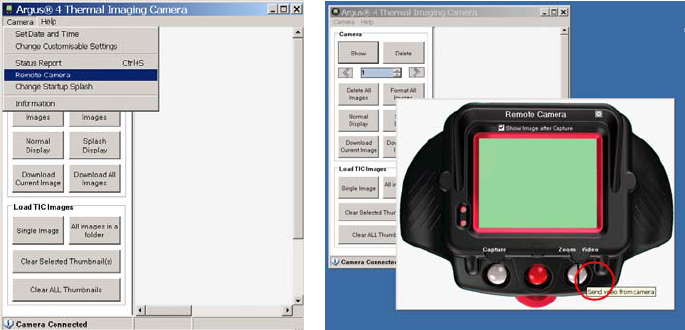
control the camera directly over the network. The control functions are accessed via the ‘Remote
Camera’ interface shown below. The right-hand button is shown split for the dual function of zoom
and switching video output transmission. The control of digital zoom, video output and picture
capture are available on this interface, while the normal customisable settings such as colour
scheme are available as normal.
6. Can I view the camera remotely or via the internet?
This is not currently implemented on the camera. Discuss any special requirements with your
distributor or e2v sales office.
This can be achieved to some extent by using a computer to relay the analogue image from an
P7030EPVA, P7030AVBP or the analogue output of the P7030DRX using a proprietary TV card or
analogue video to network conversion unit. This functionality if often available with command
vehicle systems and the camera can be interfaced to these as a video source or directly as a
compatible LRT video source.
©e2v technologies (uk) limited 2010 107553 09 Aug 2010 DAS762156AA (UK) Version 11, page 48
7. How do I change the size of the video picture on the computer display?
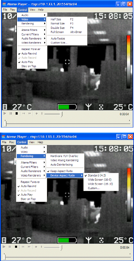
The Ateme player has several preset video sizes selected as shown below left. F4 (double size)
and ALT+ENTER (full screen) are the most likely to be of use.
It is also possible to drag the window to resize although this can have unforeseen consequences
in artefacts and aspect ratio. The recommended settings are show below.
©e2v technologies (uk) limited 2010 107553 09 Aug 2010 DAS762156AA (UK) Version 11, page 49
8. What is the battery indicator showing with the EPVA?
The battery indicator behaves normally when using a Transmitter battery pack or Analogue Output
Battery Pack, although runtime is reduced when transmitting.
The battery indicator will always show full when using the EPVA. It is not measuring the vehicle or
computer battery.
9. What camera software versions do I need?
There are some compatibility issues with early cameras of type P7030. Other camera types
(P7130, P7225 etc) are fully compatible in all software versions except as described with regard to
analogue video output.
P7030 with camera software DSP 2.17 and earlier will only work with Apple Quicktime.
P7030 with camera software DSP 2.18 functions correctly but the camera address is set to
192.168.1.20 by default. This may cause problems in locations with high wireless traffic as well as
differing from the instructions above.
P7030 with DSP software Versions 3 and above function as described in this guide. This revision
also enhances image quality and camera performance.
To work with the video recording battery pack the camera address must be set to 10.133.1.20
Consult your distributor or e2v sales office for these and any further improvements applicable to
your Argus®4 camera.
10. Can I use other players?
Any player capable of receiving an rtsp stream should display video from an Argus®4 camera. e2v
recommend and supply the Ateme player as this gives the best overall performance. Other players
that may be encountered are:
Microsoft Media Player
This does not work with rtsp streams, either in current version or the apparent derivation
‘Quicktime Alternative’. It will play recorded files from the video recording battery pack with a
suitable CODEC
Apple QuickTime
A very common installation on computers, but it is a rather heavyweight consumer focused
application that can disturb other programmes on the computer. Buffering cannot be reduced
and it does not restart; this is particularly an issue with the Wi-Fi transmitter that may come in
and out of range.
RealPlayer
A consumer-focused programme which may be felt to be excessive and too invasive for the
task. It also requires additional codecs to deal with rtsp.
VideoLAN player VLC
Open source player, some buffering can be removed but not all. Useful for forwarding and
recording, VLC also has some very good image adjustment functions not found elsewhere.
M Player
Open source player, some buffering delay can be removed but not all. Useful for forwarding
and recording, but it is not totally robust when the input stream is stopped or goes out of
reception range. Much lower loading on the computer and so may be preferred on lower
specification devices and tablet PCs. There are various user interface builds available such
as MPUI. Not all variants support rtsp.
©e2v technologies (uk) limited 2010 107553 09 Aug 2010 DAS762156AA (UK) Version 11, page 50
The following player versions have been tested using Win2000, XP-pro and XP-home:
Ateme Player: 2.1.13.2 See user CD
Quicktime: 6 and 7 http://www.apple.com/quicktime/download/win.html
VLC Player: 0.8.4a http://www.videolan.org/vlc/
MPlayer 1.0-rc1 http://www.mplayerhq.hu
MPlayer UI 1.2-pre2.35 http://mpui.sourceforge.net/
Note that both VLC and MPlayer are ‘open-source’ players with many variants available.
11. What do I need to view digital video from the P7030EPVA or P7030RKT?
The P7030RRS is a tablet PC fully configured for connection to a camera. However, if it is desired
to use a different computer or existing hardware, the following should be suitable:
• A full desktop PC, laptop PC or a Tablet/Portable PC.
• RTSP stream compatible player, such as the ATEME player supplied.
• Suitable operating systems are Windows XP (SP2 preferred), Vista or XP Embedded
(Tablets).
• Computers running Windows 2000 are also likely to function correctly although networking
set-up will differ from this manual and may not be totally robust.
• Updated Direct X video drivers may be required depending on player software used.
Tablet PCs may struggle to run the more heavyweight players; MPlayer may be preferred in these
devices.
12. What do I need to view digital video from the P7030VC?
• A full desktop PC, laptop PC or a Tablet/Portable PC.
• Suitable operating systems are Windows XP (SP2+ preferred), Vista or XP Embedded
(Tablets).
• Computers running Windows 2000 and even 98 are also likely to function correctly.
• Updated Direct X video drivers may be required depending on player software used.
Tablet PCs may struggle to run the more heavyweight players; MPlayer may be preferred in these
devices.
13. Can I view the camera on a television?
The digital output cannot be viewed on a television. The only way to connect digital video into a
television would be by using a ‘TV Out’ function on a computer.
The analogue video signal from the camera or LRT receiver may be displayed on a television or
via a video recorder by using video inputs. The connector on such devices is usually an RCA
phono socket and coloured yellow and labelled ‘AV in’ or similar, or via an adaptor into a SCART
socket. The camera does not connect to the antenna socket.
14. How do I record video?
The video recording battery pack allows recording directly from any camera as described in
section 7. Alternatively, the various players described above in FAQ 10 have differing levels of
recording capability to the computers’ memory, hard drive or a network.
A conventional ‘TV’ based video recorder can record the analogue video signal from the camera or
LRT receiver by using video inputs. The connector on such devices is usually an RCA phono
socket and coloured yellow and labelled ‘AV in’ or similar. The camera does not connect to the
antenna socket and the video is NTSC 60 Hz standard.
15. Can I change the antennas on the transmitter?
Changing the transmitter antenna may cause an infringement of regulatory requirements. The
transmitter antenna should only be replaced with an equivalent item sourced through your e2v
distributor or the factory.
©e2v technologies (uk) limited 2010 107553 09 Aug 2010 DAS762156AA (UK) Version 11, page 51
16. Can I change the antennas on the receiver?
Changing the receiver antenna may cause an infringement of regulatory requirements. The
receiver antenna should only be replaced with an alternative antenna that has a gain of up to 3
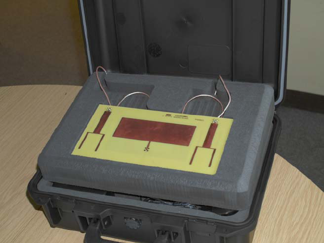
dBi. The LRT receiver allows the use of either the straight antennas or any two of the three in the
receiver station lid shown below. Further details are given in section 8 dealing with the LRT
system.
17. How do I get the maximum performance from my Wi-Fi system?
The location of the receiver unit or router should be considered carefully to ensure that there is as
clear a path as possible to the camera and transmitter. This may involve being outside of a vehicle
or selecting an alternative receiving access point, router or network adaptor.
Where a higher power signal is permitted (e.g. USA) and the user is choosing the receiver unit, it
is more beneficial to choose a high gain antenna over a higher RF power. Higher power will not
improve reception from the camera; using a lower power with a commensurately larger antenna
will give better results. If the antenna is directional, this should be pointed towards the camera.
Always check the product documentation to ensure that the resulting system is legal for operation
as intended.
Normally little can be done to the transmitter performance or location as this is attached to the
camera. As the camera transmissions are standard Wi-Fi, there are a number of ‘extender’ or
‘relay’ product accessories available from the usual Wi-Fi manufacturers and retailers that may be
of use. In a known location it may be desirable to change wireless channel to avoid any
interference sources, see FAQ 25.
18. What affects the transmitter range?
The Wi-Fi range given in the specification of 300 m is for a clear unobstructed path, for example
an open field. Penetration into a building will depend greatly upon the construction of the particular
building, with concrete and stone walls being most problematic. The presence of interference may
also have the effect of reducing range.
©e2v technologies (uk) limited 2010 107553 09 Aug 2010 DAS762156AA (UK) Version 11, page 52
The LRT system offers much greater range and has been tested between a basement and first
floor location in an adjacent building.
19. How many cameras can I connect at once?
For the Wi-Fi systems, no more than 3 cameras can be supported on a single wireless channel
due to the data rate required. Indeed, 2 may be the practical limit in many situations where other
networks are present or reception is poor. A wireless adaptor such as that offered in the
P7030RRS and P7030RKT is intended for a single connection, but this is made to the SSID. A
connection to the ‘argus4’ SSID may present 2 or 3 cameras as long as all the IP addresses are
different. In this case, the cameras can be chosen by IP address in the player software or several
instances of the player software may be run at once, computational power permitting.
Any additional cameras would require a further router or access point using a different radio
channel. With only channels 1, 6 and 11 being truly independent, the wireless connection limit is 9
assuming no other significant wireless traffic. A router may be preferred if multiple camera
operation is a regular requirement.
The limit in a wired system is the number of network sockets and achieving correct IP address
allocation, and of course the computational limits of the display computer. A router-based system
will support more than one computer but not to view the same camera.
The LRT system is limited by the number of independent RF channels available, which in turn
depends upon the local licensing conditions.
20. How many cameras can I view at once?
The receiver station and similar tablet computers are limited in computational power and may not
be able to decode more than one or two pictures at a time.
A modern PC or laptop will generally support 3 pictures at once.
The LRT system is limited by the number of independent RF channels available, which in turn
depends upon the local licensing conditions. Each receiver can be switched between any one
channel as described in section 8.
21. Are there security issues with Transmitters?
A Wi-Fi connection cannot interfere with the camera, and it is highly unlikely that a successful
viewing connection could be made without knowledge of the camera settings in this manual. The
computer should be safeguarded in the normal way with good sharing or connection passwords
and firewall/anti-virus software. It is also possible to lock to specific SSIDs or MAC addresses, or
to employ some encryption depending upon the options offered by the network equipment.
Eavesdropping is much more difficult with this system than with traditional analogue ones. Setting
encryption or changing the camera from the factory default IP address will protect the system
further. However, there is no guarantee of security with any radio-based system.
The LRT system is significantly more difficult to intercept than Wi-Fi, essentially requiring a
matching receiver.
22. Why is my wireless link connecting to another network?
This may occur when there is a stronger signal from another network nearby, or sometimes when
a network adaptor finds one of the same brand. This tendency may be reduced by using Windows
built-in wireless networking because it favours connection to the most recently-used network. It is
also possible to lock to specific SSIDs or MAC addresses depending upon the options offered by
the network equipment.
Selection of a different channel as described in FAQ 25 may also help.

©e2v technologies (uk) limited 2010 107553 09 Aug 2010 DAS762156AA (UK) Version 11, page 53
23. What IP addresses should be used by the system?
The following IP address allocations are suggested to ensure that all products have a unique
address at all times and will therefore avoid conflicts if coming within range of similar products
owned by others.
P7030 cameras are all set to 10.133.1.20 as delivered from e2v. This ensures that any camera will
appear at the same address to the player, allowing one transmitter to be shared among a number
of cameras. This does present a small risk of conflict.
Transmitter control units are set to 10.133.2xx.xxx, where xx.xxx is the serial number. Serial
numbers run from 20.001 to 20.254, 21.001 to 21.254 and so on.
Receivers sold as systems are set to 10.133.01x.xxx, where x.xxx is the serial number. Serial
numbers run from 0.001 to 0.254, 1.001 to 1.254 and so on.
It is suggested that any other computers used in ad-hoc systems are set to 10.133.0xx.xxx, where
xx.xxx is set to match the transmitter in use.
EPVAs do not have an address requirement, they are purely a connection.
A wired only system is best configured using addresses 10.133.1.xxx for the computer with
10.133.1.1 for the router or using the router default address. The subnet mask in this situation
may be set to 255.255.255.0
It is strongly recommended that cameras used in multiple camera installations are allocated
addresses in the 10.133.1xx.0xx range using their serial numbers. Camera 1234 would be given
address 10.133.112.034 by this method. This ensures unique addresses by design.
Note that this scheme requires a subnet mask set to 255.255.0.0 or wider.
10 133 1 1 Router
10 133 1 2 - 19 Computers in router systems or DHCP range for computers.
10 133 1 20 Camera manufacturer’s default.
Must be used to allow recording with P7030VC
10 133 1 21 - 254 Cameras set up in wired systems.
10 133 10 - 19 1 - 254 Receivers by serial number of receiver.
10 133 20 - 54 1 - 254 User computers set to match transmitters in ad-hoc.
10 133 100 - 199 1 - 99 Cameras reallocated to serial number based IP addresses.
10 133 220 1 Transmitter unit default when reset by magnet.
10 133 220 - 254 2 - 254 Transmitter units by serial number of transmitter.
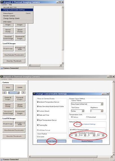
©e2v technologies (uk) limited 2010 107553 09 Aug 2010 DAS762156AA (UK) Version 11, page 54
24. How do I change the camera IP address to suit my network?
This is performed using the customer software through the USB connection to the camera as
described in the camera documentation and used for downloading pictures.
Note that the camera does not operate with automatically assigned DHCP IP addresses and that
the address selected must not be in use anywhere else on the same subnet for any device.
Therefore, in order to have two cameras connected, at least one IP address must be changed.
If using wireless, remember to consider the control module address as well. If any address is
duplicated, the system will not work. As indicated in FAQ 23 above, a transmitter serial number
20.017 will have the transmitter control module address set to 10.133.220.17.
The Video Capture Battery Pack will only record from a camera with IP address 10.133.1.20
Run the customer software.
Select the ‘Change
Customisable Settings’
option.
Tick the ‘Change Network
Settings’ box.
Enter the desired IP
address.
Click ‘Save to Camera’.

©e2v technologies (uk) limited 2010 107553 09 Aug 2010 DAS762156AA (UK) Version 11, page 55
25. How do I change the Wi-Fi channel or other settings?
This may be of use where there is a known source of interference, for example another Wi-Fi
system. Note that, although there are up to 14 channels, several are not permitted in most
countries and that only 1, 6 and 11 are independent.
The adjustment of these settings in the module is different across the various versions of module
firmware; please consult the factory for assistance. In some instances familiarity with TELNET
access is required while other modules are accessible using a web interface.
Do not change channels unless certain that the system will be legal at all
times by using the correct router settings.
Operation on channels 9 – 13 (above 2454 MHz) is not permitted outdoors in
France.
Check http://www.art-telecom.fr/ for more details.
Là où utilisé dehors, creuser des rigoles seulement 1 – 8 (2400-
2454 MHz) peuvent être employés.
Visitez http://www.art-telecom.fr/ pour de plus amples détails.
26. How do I change the LRT channel or other settings?
Do not change power or frequency unless certain that the system will be legal
at all times.
The frequency, bandwidth and power settings should only be changed by
competent persons who have a thorough understanding of the legal
implications of the local license conditions for radio transmission.
Transmission with improper settings may be an offence in your location.
The other settings such as the FEC and guard interval settings have been chosen to give the best
range in a difficult environment; they were set while testing a transmitter in a basement being
received in the first floor of a nearby building. It should not be necessary to alter these for most
uses and a mismatch between transmitter and receiver may cause the system to cease
functioning. The only exception would be use with a command vehicle where the transmitter is to
be set to suit the system in the vehicle or to implement higher security settings. If in doubt, the
installer should contact e2v in this case to determine the best approach.
27. How do I license the LRT transmitter?
Consult your local radio authorities for details of frequencies and permitted powers for your
location. Contact details are given in section 15 and 16 or your local distributor may be able to
assist. The authorities will need a copy of the DTX RF data from section 12. Using a licensed
frequency will generally allow higher power and reduced interference, which will both improve the
system performance.
In many countries, low power use is permitted in the 2400 – 2483.5 MHz area without a licence.
However this is likely to result in lower performance due to the power restrictions and interference
from other licence-exempt uses.

©e2v technologies (uk) limited 2010 107553 09 Aug 2010 DAS762156AA (UK) Version 11, page 56
SECTION 12 - Specifications
Wi-Fi Systems
Operating frequency - 2.4 GHz
Data format - 320 x 240 pixel colour camera image at 10 fps
MPEG 4 RTSP video stream over port 554 at 600 kb/s
Range - Up to 350 m (1150 feet) line of sight.
Performance in buildings is dependent upon construction.
Interference and other transmitting devices may also reduce range.
Transmission standard – IEE802.11b
Data rate approximately 600 kbps
Transmitter P7030TX
Battery Data
Battery type - Ni-MH Rechargeable
Capacity - 2000 mAH
Battery life - 3 hours @ ambient temp 22 °C (72 °F) transmitting
4 hours @ ambient temp 22 °C (72 °F) not transmitting
Charge time - 2 hours nominal
Recharge cycles - 500 to 80% initial capacity
Mechanical Data
Overall dimensions - with antenna (H x W x D) - 189 x 126 x 69 mm (7.5 x 5.0 x 2.7 inch)
without antenna (H x W x D) - 59 x 126 x 69 mm (2.3 x 5.0 x 2.7 inch)
Weight - 380 g (14 oz) nominal
Environmental Data
Operating temperature - The Transmitter Battery Pack will operate the Argus®4 in the same
rugged environments as the standard battery.
Sealing - The Transmitter Battery Pack is sealed to IP67.
Storage -
The Transmitter Battery Pack can be stored for short periods but to
maintain cell life periodic recharging is recommended. It is
recommended that for maximum effective operational life, the
storage temperature is kept between –10 °C and +40 °C (14 °F and
104 °F).
Performance Data
Output Power - EU classification Class 2
100 mW EIRP max.
Receiver Station P7030RRS
The exact device supplied may vary from that shown due to IT product evolution. The following
basic requirements will be met:
Connectivity - USB to network adaptor
Lead length - 1.5m between receiver and antenna location - extendable
Transmission standard - IEE802.11b

©e2v technologies (uk) limited 2010 107553 09 Aug 2010 DAS762156AA (UK) Version 11, page 57
Receiver Kit P7030RKT
The exact device supplied may vary from that shown due to IT product evolution. The following
basic requirements will be met:
Connectivity - USB
Lead length - 1.5 m
Transmission standard - 2.4 GHz
External Power and Video Adaptor P7030EPVA
Electrical
Power Connector – Vehicle accessory plug, centre positive
Input voltage - 10 – 32 V (12 V and 24 V vehicle systems)
Power consumption - Typically 5 W with camera operating
Data Connector -
Woodhead RJ-Lnxx series
Compatible with standard RJ45
Format -
Added cable length - 100 m Cat 5E supported to typical router/computer
Video Signal 1 V p - p 75 Ω
NTSC 525-line 60 Hz (EIA RS-170)
Mechanical
Overall
dimensions Battery replacement unit (H x W x D) - 60 x 125 x 65mm (2.4 x 5 x 2.5 inch)
Interconnect cable 1.7 m (67 inches)
Junction box (H x W x D) 60 x 120 x 80 mm (2.4 x 4.7 x 3.2 inch)
DC cable - 1.2 m (48 inches)
Weight 690 g (1 pound 8 oz.)
Environmental Data
Thermal conditions - Maximum operating temperature is 75 °C (165 °F)
Minimum operating temperature is –10 °C (14 °F)
Sealing - Battery Replacement Unit IP67
Junction Box IP54 - only when using approved connectors.
Storage - The EPVA can be stored for extended periods. It is recommended that for
maximum effective operational life, the storage temperature be kept
between –10 °C and +40 °C (14 °F and 104 °F) when not in use.
RFI/EMC Emissions (LAN mode) 72/245/EC (as amended by 2006/28/EC)
EN55022:2006 Class A
FCC CFR-47 Part 15 Class A
ICES-003 Issue 4
AUS/NZ CISPR22:2006
(Video mode) 72/245/EC (as amended by 2006/28/EC)
BS EN 61000-6-3:2007
FCC Part 15B class B
AUS/NZ 61000-6-3:2007
RFI/EMC Immunity (LAN mode) 72/245/EC (as amended by 2006/28/EC)
EN55024 A2: 2003
(Video mode)
72/245/EC (as amended by 2006/28/EC)
BS EN 61000-6-2:2005
Safety IEC 60950-1 and related national standards
Vibration / Shock BS EN 60721-3-2 Class 2M2.
Warning: Operating in LAN mode this is a class A product. In a domestic environment this product
may cause radio interference in which case the user may be required to take adequate measures.

©e2v technologies (uk) limited 2010 107553 09 Aug 2010 DAS762156AA (UK) Version 11, page 58
Analogue Output Battery Pack P7030AVBP
Battery Data
Battery type - Ni-MH Rechargeable
Capacity - 2000 mAH
Battery life - 4 hours @ ambient temp 22 °C (72 °F)
Charge time - 2 hours nominal
Recharge cycles - 500 to 80% initial capacity
Video Output
Connector - BNC 75 Ω
Signal Format - 1 V p - p 75 Ω
NTSC 525-line 60 Hz (EIA RS-170)
Mechanical
Overall dimensions (H x W x D) - 60 x 125 x 65 mm (2.4 x 5 x 2.5 inch)
Weight 315 g (11 oz)
Environmental Data
Operating temperature - The Analogue Output Battery Pack will operate the Argus®4 in the
same rugged environments as the standard battery.
Sealing - The Analogue Output Battery Pack is sealed to IP67.
Storage -
The Analogue Output Battery Pack can be stored for short periods but
to maintain cell life periodic recharging is recommended. It is
recommended that for maximum effective operational life, the storage
temperature is kept between –10 °C and +40 °C (14 °F and 104 °F).
RFI/EMC Emissions BS EN 61000-6-3:2007
FCC Part 15B class B
ICES-003 Issue 4
AUS/NZ 61000-6-3:2007
Immunity BS EN 61000-6-2:2005
Safety IEC 60950-1 and related national standards
Vibration / Shock BS EN 60721-3-2 Class 2M2.

©e2v technologies (uk) limited 2010 107553 09 Aug 2010 DAS762156AA (UK) Version 11, page 59
Video Capture Battery Pack P7030VC
Battery Data
Battery type - Ni-MH Rechargeable
Capacity - 2000 mAH
Battery life - 3 hours @ ambient temp 22 °C (72 °F) recording
4 hours @ ambient temp 22 °C (72 °F) not recording
Charge time - 2 hours nominal
Recharge cycles - 500 to 80% initial capacity
Data Output
Connector - Fischer 102 series
Use the lead supplied with camera (P7030PC) to convert to a standard
USB A plug
Video Format - MPEG-4 320 x 240 10 Hz
Mechanical
Overall dimensions (H x W x D) - 60 x 125 x 65 mm (2.4 x 5 x 2.5 inch)
Weight 315 g (11 oz)
Environmental Data
Operating temperature - The Video Storage Battery Pack will operate the Argus®4 in the same
rugged environments as the standard battery.
Sealing - The Video Storage Battery Pack is sealed to IP67.
Storage -
The Video Storage Battery Pack can be stored for short periods but to
maintain cell life periodic recharging is recommended. It is
recommended that for maximum effective operational life, the storage
temperature is kept between –10 °C and +40 °C (14 °F and 104 °F).
RFI/EMC Emissions BS EN 61000-6-3:2007
FCC Part 15B class B
ICES-003 Issue 4
AUS/NZ 61000-6-3:2007
Immunity BS EN 61000-6-2:2005 (Recording)
EN 55024/A2:2003 (Playback)
Safety IEC 60950-1 and related national standards
Vibration / Shock BS EN 60721-3-2 Class 2M2.

©e2v technologies (uk) limited 2010 107553 09 Aug 2010 DAS762156AA (UK) Version 11, page 60
LRT Transmitter DTX1400 and DTX2400
Battery Data
Battery type - Ni-MH Rechargeable
Capacity - 2000 mAH
Battery life - >75 minutes @ ambient temp 22 °C (72 °F) transmitting
4 hours @ ambient temp 22 °C (72 °F) not transmitting
Charge time - 2 hours nominal
Recharge cycles - 500 to 80% initial capacity
Mechanical Data
Overall dimensions - with 1400antenna (H x W x D)
with 2400antenna (H x W x D) 189 x 126 x 69 mm (7.5 x 5.0 x 2.7 inch)
150 x 126 x 69 mm (6.0 x 5.0 x 2.7 inch)
without antenna (H x W x D) - 59 x 126 x 69 mm (2.3 x 5.0 x 2.7 inch)
Weight - 430 g (15 oz) nominal
Environmental Data
Operating temperature - The Transmitter will operate the Argus®4 in the same rugged
environments as the standard battery.
Sealing - The Transmitter is sealed to IP67.
Storage -
The Transmitter can be stored for short periods but to maintain cell
life periodic recharging is recommended. It is recommended that for
maximum effective operational life, the storage temperature is kept
between –10 °C and +40 °C (14 °F and 104 °F).
RF Data
Frequency range L-band 1200 to 1400 MHz
Frequency range S-band 2200 to 2500 MHz
Bandwidth 2.5 MHz
Modulation QPSK
FEC 1/3
ITU designator
2M50D7FEF
(ITU radio regulations Article 4 & Appendix 6)
If using the 1.25MHz bandwidth the designator is 1M25D7FEF
Duty cycle 100%
Output power 200 mW EIRP max. (100mW with 3dB gain antenna)
Transmitter standards
L-band EN 300 440-2
Transmitter standards
S-band
EN 302 064-2
FCC CFR47 Part 90
AS/NZS 4268:2008
RFI/EMC Emissions EN 301 489-28
Immunity EN 301 489-28
Safety IEC 60950-1 and related national standards
Vibration / Shock BS EN 60721-3-2 Class 2M2.

©e2v technologies (uk) limited 2010 107553 09 Aug 2010 DAS762156AA (UK) Version 11, page 61
LRT Receiver DRX1400 and DRX2400
Mechanical Data
Overall dimensions - without antenna (H x W x D) - 189 x 290 x 65 mm
(7.5 x 11.5 x 2.4 inch)
Weight - 2 kg (4lb 6 oz) nominal
Environmental Data
Operating temperature - –10 °C to +50 °C
–10 °C to +40 °C battery charging
Sealing - The Receiver is splash-proof to IP42.
Storage -
The receiver can be stored for short periods. It is recommended that
for maximum effective operational life, the storage temperature is
kept between –10 °C and +40 °C (14 °F and 104 °F).
RFI/EMC Emissions EN 301 489-28
Immunity EN 301 489-28
Safety IEC 60950-1 and related national standards
Vibration / Shock BS EN 60721-3-2 Class 2M2.
Battery Data
Battery type - Lithium Ion Rechargeable
Capacity - 5200 mAH
Battery life - 2 hours @ ambient temp 22 °C (72 °F)
Charge time - 3 hours nominal
Recharge cycles - 300 to 70% initial capacity
Charger Data (AC Mains Version)
Input voltage 100 – 240 V nominal 50/60 Hz
Connection Interchangeable mains plugs supplied
Output 1.5 A 12.6 V
Environmental Operating temperature –20 to +40 °C
Sealing IP41
Overall dimensions - (H x W x D) - 70 x 110 x 37 mm
(2.5 x 4.2 x 1.4 inch)
Weight - 270 g (10 oz) nominal
Charger Data (DC Version)
Input voltage 10 – 30V nominal
Connection
1.2m / 4 foot DC lead with car
accessory plug fitted, 5A fuse
Output 2.3A 12.6 V
Environmental Operating temperature –20 to +40 °C
Sealing IP41
Overall dimensions - Excluding wires (H x W x D) - 65 x 110 x 37 mm
(2.5 x 4.2 x 1.4 inch)
Weight - 270 g (10 oz) nominal

©e2v technologies (uk) limited 2010 107553 09 Aug 2010 DAS762156AA (UK) Version 11, page 62
LRT Receiver Station DRRS1400 and DRRS2400
Mechanical Data
Overall dimensions - (H x W x D) - 415 x 320 x 165 mm
(16.4 x 12.6 x 6.5 inch)
Weight - 5 kg nominal
Environmental Data
Sealing - The Receiver is splash-proof with the lid open
The receiver station is IP67 when closed and locked.
Storage -
The receiver can be stored for short periods. It is recommended that
for maximum effective operational life, the storage temperature is
kept between –10 °C and +40 °C (14 °F and 104 °F).
Functional data as DRX1400 or DRX2400 respectively
©e2v technologies (uk) limited 2010 107553 09 Aug 2010 DAS762156AA (UK) Version 11, page 63
SECTION 13 - FCC Statement (All products)
NOTE: Unless specified elsewhere described in this user guide this equipment has been tested by
verification and found to comply with the limits for a Class B digital device, pursuant to Part 15 of
the FCC Rules.
The P7030EPVA operating in LAN mode is a class A product. In a domestic environment this
product may cause radio interference in which case the user may be required to take adequate
measures.
Operation is subject to the following two conditions:
1. This device may not cause harmful interference, and
2. This device must accept any interference received, including interference that may cause
undesired operation.
These limits are designed to provide reasonable protection against harmful interference in a
residential installation. This equipment generates uses and can radiate radio frequency energy
and, if not installed and used in accordance with the instructions, may cause harmful interference
to radio communications. However, there is no guarantee that interference will not occur in a
particular installation.
If this equipment does cause harmful interference to radio or television reception, which can be
determined by turning the equipment off and on, the user is encouraged to try to correct the
interference by one or more of the following measures:
· Reorient or relocate the receiving antenna.
· Increase the separation between the equipment and receiver.
· Connect the equipment into an outlet on a circuit different from that to which the receiver
is connected.
· Consult the dealer or an experienced radio/TV technician for help.
Any changes or modifications not expressly approved by e2v technologies (uk) limited could
invalid the user’s authority to operate the equipment.
INFORMATION FOR CANADIAN USERS (IC NOTICE)
This Class A / B digital apparatus complies with Canadian ICES-003.
Cet appareil numérique de la classe A/ B est conforme à la norme NMB-003 du Canada.
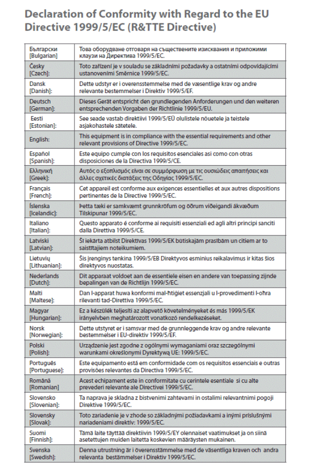
©e2v technologies (uk) limited 2010 107553 09 Aug 2010 DAS762156AA (UK) Version 11, page 64
SECTION 14 - Compliance and Legal Notices (P7030TX Transmitter)
Compliance Information for 2.4 GHz Wireless Products, relevant to the EU and other countries
following the EU Directive 1999/5/EC (R&TTE Directive).
The transmitter is a class 2 device.

©e2v technologies (uk) limited 2010 107553 09 Aug 2010 DAS762156AA (UK) Version 11, page 65
CE Marking
The following standards were applied during the assessment of the product against the
requirements of the Directive 1999/5/EC: Radio: EN 300 328
EMC: EN 301 489-1, EN 301 489-17
Safety: EN 60950
For all products, the Declaration of Conformity is available below and as a .pdf file on the product
CD. For the P7030TX Transmitter and Battery Pack, the following CE mark, and notified body
number where applicable, are added to the equipment.
National Restrictions
This product may be used in the following EU countries (see limitations for France and Italy).
Ce produit peut être employé dans les pays suivants d'EU (voir les limitations pour la France et
l'Italie).
Questo prodotto può essere usato nei seguenti paesi di UE (veda le limitazioni per la Francia e
l'Italia).
Dieses Produkt kann in den folgenden EU-Ländern benutzt werden (sehen Sie Beschränkungen
für Frankreich und Italien).
AT BE CZ FR DE GR IE IT NL PL
PT ES SE GB NO CH
Les liaisons sans fil pour une utilisation en extérieur d’une distance supérieure à 300 mètres
doivent être notifiées à l’Institut Belge des services Postaux et des Télécommunications (IBPT).
Visitez http://www.ibpt.be pour de plus amples details.
France
Where used outdoors, only channel 1 – 8 (2400 - 2454 MHz) may be used.
Check http://www.art-telecom.fr/ for more details.
Là où utilisé dehors, creuser des rigoles seulement 1 – 8 (2400 - 2454 MHz) peuvent être
employés. Visitez http://www.art-telecom.fr/ pour de plus amples détails.
Italy
This product meets the National Radio Interface and the requirements specified in the National
Frequency Allocation Table for Italy. Unless operating within the boundaries of the owner’s
property, the use of this 2.4 GHz Wireless LAN product requires a ‘general authorization’. Check
with http://www.comunicazioni.it/it/ for more details.
Questo prodotto è conforme alla specifiche di Interfaccia Radio Nazionali e rispetta il Piano
Nazionale di ripartizione delle frequenze in Italia. Se non viene installato all’interno del proprio
fondo, l’utilizzo di prodotti Wireless LAN a 2.4 GHz richiede una “Autorizzazione Generale”.
Consultare http://www.comunicazioni.it/it/ per maggiori dettagli.
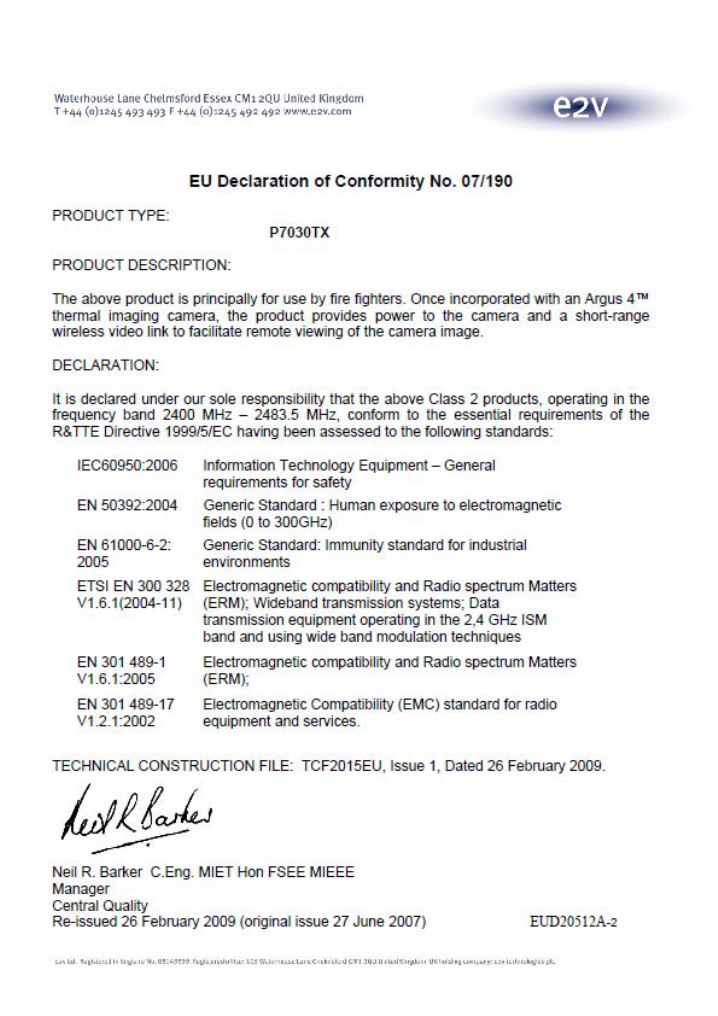
©e2v technologies (uk) limited 2010 107553 09 Aug 2010 DAS762156AA (UK) Version 11, page 66
©e2v technologies (uk) limited 2010 107553 09 Aug 2010 DAS762156AA (UK) Version 11, page 67
FCC STATEMENT
The P7030TX Transmitter and battery pack includes a radio module that has been tested and
found to comply with FCC part 15C. The FCC Identifier is RTAB-WLNB which is shown on the
label fitted to the side of the unit.
The P7030TX Transmitter and battery pack does not contain as user adjustable components.
Any unauthorised modification would invalidate the FCC certification.
FCC RF EXPOSURE STATEMENT
To satisfy RF expose requirements, this device and its antenna must operate with a separation
distance of a least 20 cm from all persons and must not be co-located or operating in conjunction
with any other antenna or transmitter.
INFORMATION FOR CANADIAN USERS (IC NOTICE)
This Class B digital apparatus complies with Canadian ICES-003.
Cet appareil numérique de la classe B est conforme à la norme NMB-003 du Canada.
This device has been designed to operate with an antenna having a maximum gain of 3 dBi.
Antenna having a higher gain is strictly prohibited per regulations of Industry Canada. The
required antenna impedance is 50 Ω.
To reduce potential radio interference to other users, the antenna type and its gain should be so
chosen than the equivalent isotropic radiated power (EIRP) is not more than the required for
successful communication.

©e2v technologies (uk) limited 2010 107553 09 Aug 2010 DAS762156AA (UK) Version 11, page 68
SECTION 15 - Compliance and Legal Notices
(DTX1400 LRT Transmitter)
Compliance Information for 1.4 GHz Wireless Products, relevant to the EU and other countries
following the EU Directive 1999/5/EC (R&TTE Directive).
The transmitter is a Class 2 device.
Declaration of Conformity with regard to the EU directive 1999/5/EC (R&TTE Directive)
English
UK This equipment is in compliance with the essential requirements and other
provisions of Directive 1999/5/EC
Nederlands
[Dutch] NL Dit apparaat voldoet aan de essentiele eisenen andere van toepassing zijnde
bepalingen van de Richtlijn 1999/5/EC
CE Marking
The following standards were applied during the assessment of the product against the
requirements of the Directive 1999/5/EC: Radio: EN 300 440-2
EMC: EN 301 489-28
Safety: EN 60950
For all products, the Declaration of Conformity is available below and as a .pdf file on the product
CD.
For the DTX1400 Transmitter and Battery Pack, the following CE mark is added to the equipment.
National Restrictions
This product may be used in the following EU countries.
Ce produit peut être employé dans les pays suivants d'EU.
Questo prodotto può essere usato nei seguenti paesi di UE.
Dieses Produkt kann in den folgenden EU-Ländern benutzt werden .
NL GB
A licence is not required in the UK for operation between 1389 and 1399 MHz at up to 500 mW
EIRP (i.e. centre frequencies 1391 – 1397 MHz). The 0 dB attenuation setting may therefore be
used with a 3 dB antenna (200 mW e.i.r.p.)
A licence is required to operate on any other frequency in the UK and may not be granted. It is the
user’s responsibility to obtain a licence.
A licence is required in the Netherlands for the use of the frequency band 1375 to 1400 MHz
(Frequencies 1377 – 1398 MHz). It is the user’s responsibility to obtain a license.
Een licentie is nodig in Nederland voor het gebruik van de frequentieband 1375 tot 1400 MHz.
(Frequentie 1377 – 1398 MHz) Het is de verantwoordelijkheid van de gebruikers het verkrijgen
van een licentie.

©e2v technologies (uk) limited 2010 107553 09 Aug 2010 DAS762156AA (UK) Version 11, page 69

©e2v technologies (uk) limited 2010 107553 09 Aug 2010 DAS762156AA (UK) Version 11, page 70
SECTION 16 - Compliance and Legal Notices
(DTX2400 LRT Transmitter)
Compliance Information for 2.4 GHz Wireless Products, relevant to the EU and other countries
following the EU Directive 1999/5/EC (R&TTE Directive).
The transmitter is a Class 2 device.

©e2v technologies (uk) limited 2010 107553 09 Aug 2010 DAS762156AA (UK) Version 11, page 71
CE Marking
The following standards were applied during the assessment of the product against the
requirements of the Directive 1999/5/EC: Radio: ETSI EN302064-2
EMC: EN 301 489-28
Safety: EN 60950
For all products, the Declaration of Conformity is available below and as a .pdf file on the product
CD.
For the DTX2400 Transmitter and Battery Pack, the following CE mark is added to the equipment.
This product can be used through EU member states as Sub class 22 device when using the
frequency range 2400 to 2454 MHz (operating frequency 2402 – 2552MHz) and an EIRP less than
25 mW.
National Restrictions
This product may be used at higher power levels in the following countries within the EEA.
Ce produit peut être employé dans les pays suivants d'EEA.
Questo prodotto può essere usato nei seguenti paesi di AEE.
Dieses Produkt kann in den folgenden EEA-Ländern benutzt werden.
DE DK FR IE NL NO ES
Germany (DE)
Frequencies are available by licence in the frequency range 2347 to 2385 MHz.
Die Häufigkeiten sind die Lizenzen im Frequenzbereich von 2347 bis 2385 MHz verfügbar.
Demark (DK)
Frequencies are available by licence up to 500 mW EIRP in the following frequency range 2310 -
2400 MHz.
Frekvenser til rådighed med tilladelse op til 500 mW EIRP i følgende frekvensområdet 2310 - 2400
MHz.
France (FR)
Frequencies are available by licence in the following frequency range 2400 - 2483.5 MHz.
Les fréquences sont disponibles par voie de licence dans la gamme de fréquences suivantes
2400 - 2483,5 MHz.
Visitez http://www.art-telecom.fr/ pour de plus amples détails.
Ireland (IE)
Com Reg 08/08 specifies frequencies from 2205 to 2295 MHz up to 1 W EIRP available by short-
term licences.
Netherlands (NL)
Frequencies are available by licence up to 1 W EIRP in the following frequency ranges 2322 to
2347, 2357 to 2382 and 2392 to 2417 MHz.
Frequenties zijn beschikbaar via vergunning tot 1 W EIRP in de volgende frequentiegebieden
2322-2347, 2357 tot 2382 en 2392 tot 2417 MHz.
©e2v technologies (uk) limited 2010 107553 09 Aug 2010 DAS762156AA (UK) Version 11, page 72
Norway (NO)
Frequencies are available licence exempt up to 2 W EIRP with operating frequencies of 2327 and
2390 MHz. Other frequencies are available under licence.
Spot frekvenser for 2327 og 2390 MHz finnes konsesjon fritatt opptil 2W EIRP. Andre frekvenser
er tilgjengelig under lisensen.
Spain (ES)
UN-109 (National Picture of Attribution of Frequencies (C.N.A.F.) specifies that the spot
frequencies of 2421, 2449 and 2477 MHz are available and is licence exempt up to 500 mW
EIRP.
De las Naciones Unidas-109 (Foto Nacional de Atribución de Frecuencias (CNAF) especifica que
el terreno de las frecuencias de 2421, 2449 y 2477 MHz están disponibles y está exenta de
licencia de hasta 500 mW PIRE.
Switzerland (CH)
Frequencies are available by licence up to 4 W EIRP in the following frequency range 2290 - 2400
MHz.
Les fréquences sont disponibles par voie de licence jusqu'à 4 W PIRE dans la bande de
fréquences 2290 - 2400 MHz suivante.
Die Häufigkeiten sind die Lizenzen bis zu 4 W EIRP in den folgenden Frequenzbereich 2290 -
2400 MHz.
USA and Canada
This product can be licensed under FCC part 90 within the frequency range 2450 to 2483.5 MHz
up to a power limit of 5W EIRP. Allowed operating frequencies are therefore 2452 – 2481 MHz
allowing for signal bandwidth.
Australia
This product may be used under LIPD Class Licence (item 45A) in the frequency band 2400 to
2483.5 MHz up to a power limit 500 mW EIRP’
Allowed operating frequencies are therefore 2403 – 2481 MHz allowing for signal bandwidth.

©e2v technologies (uk) limited 2010 107553 09 Aug 2010 DAS762156AA (UK) Version 11, page 73
©e2v technologies (uk) limited 2010 107553 09 Aug 2010 DAS762156AA (UK) Version 11, page 74
FCC STATEMENT
The DTX2400 LRT Transmitter includes a radio module that has been tested and found to comply
with FCC part 90. The FCC Identifier is PW9-DTX2400, which is shown on the label fitted to the
side of the unit.
The DTX2400 LRT Transmitter is only certified for use with antenna with a gain up to +3 dBi.
The DTX2400 LRT Transmitter does not contain any user adjustable components.
Any unauthorised modification would invalidate the FCC certification.
FCC RF EXPOSURE STATEMENT
To satisfy RF expose requirements, this device and its antenna must operate with a separation
distance of a least 20 cm from all persons and must not be co-located or operating in conjunction
with any other antenna or transmitter.
INFORMATION FOR CANADIAN USERS (IC NOTICE)
This Class B digital apparatus complies with Canadian ICES-003.
Cet appareil numérique de la classe B est conforme à la norme NMB-003 du Canada.
This device has been designed to operate with an antenna having a maximum gain of 3 dBi.
Antenna having a higher gain is strictly prohibited per regulations of Industry Canada. The
required antenna impedance is 50 Ω.
To reduce potential radio interference to other users, the antenna type and its gain should be so
chosen than the equivalent isotropic radiated power (EIRP) is not more than the required for
successful communication.
©e2v technologies (uk) limited 2010 107553 09 Aug 2010 DAS762156AA (UK) Version 11, page 75
SECTION 17 - Warranty
1. EXPRESS WARRANTY
e2v Technologies ("e2v") warrants that this product is free from mechanical defects or faulty
workmanship for one (1) year from the date of shipment, provided it is maintained and used in
accordance with e2v’s instructions and/or recommendations. This warranty does not apply to
expendable or consumable parts whose normal life expectancy is less than one (1) year.
Replacement parts and repairs are warranted for ninety (90) days from the date of shipment.
e2v shall be released from all obligations under this warranty in the event that persons other
than its own or authorised service personnel make repairs or modifications, or if the warranty
claim results from misuse of the product. No agent, employee or representative of e2v may bind
e2v to any affirmation, representation or modification of this warranty concerning the goods sold
under this contract.
THIS WARRANTY IS IN LIEU OF ALL OTHER WARRANTIES, EXPRESS, IMPLIED OR
STATUTORY, AND IS STRICTLY LIMITED TO THE TERMS HEREOF. E2V SPECIFICALLY
DISCLAIMS ANY WARRANTY OF MERCHANTABILITY OR OF FITNESS FOR A
PARTICULAR PURPOSE.
2. EXCLUSIVE REMEDY
It is expressly agreed that the Purchaser’s sole and exclusive remedy for breach of the above
warranty, for any tortuous conduct of e2v, or for any other cause of action, shall be the repair
and/or replacement, at e2v’s option, of any equipment or parts thereof, that after examination by
e2v are proven to be defective. Replacement equipment and/or parts will be provided at no cost
to the purchaser, F.O.B. e2v’s plant. Failure of e2v to successfully repair any non-conforming
product shall not cause the remedy established hereby to fail of its essential purpose.
3. EXCLUSION OF CONSEQUENTIAL DAMAGES
PURCHASER SPECIFICALLY UNDERSTANDS AND AGREES THAT UNDER NO
CIRCUMSTANCES WILL e2v BE LIABLE TO PURCHASER FOR ECONOMIC, SPECIAL,
INCIDENTAL OR CONSEQUENTIAL DAMAGES OR LOSSES OF ANY KIND
WHATSOEVER INCLUDING, BUT NOT LIMITED TO, LOSS OF ANTICIPATED PROFITS
AND ANY OTHER LOSS CAUSED BY REASON OF THE NON-OPERATION OF THE
GOODS. THIS EXCLUSION IS APPLICABLE TO CLAIMS FOR BREACH OF WARRANTY,
TORTIOUS CONDUCT OR ANY OTHER CAUSE OF ACTION AGAINST e2v.
©e2v technologies (uk) limited 2010 107553 09 Aug 2010 DAS762156AA (UK) Version 11, page 76
User Notes
©e2v technologies (uk) limited 2010 107553 09 Aug 2010 DAS762156AA (UK) Version 11, page 77
e2v technologies (uk) limited
Waterhouse Lane
Chelmsford
Essex CM1 2QU, UK
Telephone: +44 (0)1245 493493
Facsimile: +44 (0)1245 492492
e2v technologies inc.
520 White Plains Road, Suite 450
Tarrytown
NY 10591, USA
Telephone: (914) 592 6050
Facsimile: (914) 592-5148
e2v technologies sas
16 Burospace
F-91572 Bièvres Cedex, France
Telephone: (0)16019 5500
Facsimile: (0)16019 5529
e2v technologies GmbH
Industriestrasse 29
D-82194 Gröbenzell, Germany
Telephone: (0)8142 410570
Facsimile: (0)8142 284547
Internet: www.argusdirect.com