E2V Technologies P4467-T2 Argus® 3 P4467-T2 Thermal Imaging Camera User Manual 702198AA 1 39
E2V Technologies Ltd. Argus® 3 P4467-T2 Thermal Imaging Camera 702198AA 1 39
Contents
- 1. Argus 3 user manual
- 2. Argus 3 users manual
Argus 3 user manual
ARGUS
1
3
Firefighters’ Solid-State
Through Smoke
Vision System
User’s Manual and Warranty Terms
Argus
1
- Trademark licensed from Argus Industries, Inc.
#e2v technologies limited 2003 DAS702198AA, Issue 2

SAFETY NOTES
ARGUS
1
3
THERMAL IMAGING CAMERA
and CHARGER/BATTERY PACKS
Please read before use
This product is an aid to fire and rescue operations in smoke and darkness.
It is not intended as a replacement for standard firefighting techniques. Users
must ensure that all established procedures are followed.
This equipment is not certified as intrinsically safe and therefore must not
be operated in flammable or explosive atmospheres.
Neglecting the above may result in injury or death.
An auto-iris adjusts sensitivity allowing very hot scenes to be viewed. This
circuitry also protects the camera from damage.
To avoid damage:
"The camera should be switched on before entering a fire situation and
remain on until after exit.
"When switched off, the camera should not be directed towards very hot
objects, e.g. the sun. We recommend that it is stored in the supplied case or
storage mount.
WARNINGS indicate a hazard. Failure to appreciate the hazard could result in
personal injury or death. Do not proceed until the hazard is understood.
CAUTIONS indicate a hazard. Failure to appreciate the hazard could result in
severe damage to the unit. Do not proceed until the hazard is understood.
Notes provide useful information.

WARNINGS
Electrical hazards
Do not remove the cover of the charger, or disassemble the charger power lead
or rechargeable pack. There are no user serviceable parts within the charger,
charger lead or the rechargeable pack.
Charger misuse
The charger must only be used for the charging of rechargeable packs; do not
insert any other item into the charger. The charger must not be used to charge
primary cells; the charger will not accept the primary cell pack. Do not use a
damaged charger. Do not attempt to charge damaged packs.
Disposal
The Ni-MH cells contained within the pack must be disposed of in accordance
with local regulations. Do not incinerate. Do not attempt to charge damaged
packs.
Environmental
The charger must not be subjected to water spray, rain or immersion.
CAUTION
The Camera and Rechargeable Battery System are despatched from e2v
technologies in a safe condition. Any unauthorised modifications may
compromise safety and invalidate the warranty. The Camera and Rechargeable
Battery System are designed to be safe when used in accordance with the
instructions provided.
e2v technologies does not accept responsibility for damage or injury resulting
from failure to follow the instructions provided.
All matters arising which relate to the safety of products should be reported
immediately, in writing, giving full details to The Product Safety Officer at e2v
technologies.
NOTE
The Argus
1
3 BST thermal image camera contains an export-controlled
component and may not be shipped to another country without the prior
approval of the US Government, which should be requested from e2v
technologies.
Introduction
ARGUS
1
3
Thermal Imager
The Argus
1
3 thermal imager is brought to you by e2v technologies, the world
leader in through smoke vision systems.
e2v technologies, with over 18 years experience in firefighters’ thermal imaging,
continues to produce high quality, affordable systems designed exclusively for
the fire and rescue services.
Argus
1
3 uses the latest high resolution, solid-state FPA detector or
microbolometer technology to provide superb quality images under the most
arduous conditions while retaining the class-leading ergonomics of the previous
Argus
1
systems.
Through the proper use of this Argus
1
3 system, the user will be able to:
.See through dense smoke and darkness.
.Detect and display the relative temperatures of objects within the scene.
.Locate the seat and spread of the fire.
.Move swiftly in search and rescue of casualties.
.See in zero visibility conditions.
.Significantly improve safety and mobility.
Argus
1
3 is designed to withstand the high temperatures, knocks and driving
spray often encountered in the firefighting environment.
1
Argus
1
3 has also been designed with the following features:
.Capture of 26 images.
.Time and date.
.2x zoom.
.Ambient temperature measurement.
.Choice of 8 colour palettes.
.Spot temperature (optional).
.Internal video transmitter (optional).
This manual contains information covering operation of the system and
operating techniques, user maintenance and care of the product, complete with
a full technical specification.
2
Contents
Page
1 Camera ....................... 4
1.1 GETTING STARTED ..................4
1.2 DISPLAY GRAPHICS ..................6
1.3 OPERATING NOTES ..................8
2 Standard Functions .................. 11
2.1 IMAGE CAPTURE .................. 11
2.2 ZOOM ...................... 11
2.3 TIME AND DATE .................. 11
2.4 AMBIENT TEMPERATURE ............... 12
3 Optional Functions .................. 13
3.1 SPOT TEMPERATURE MEASUREMENT .......... 13
3.2 TRANSMITTER ................... 13
3.3 RECEIVER KITS ................... 14
4 Remote Control Functions ............... 16
5 Software ...................... 18
6
Cleaning, Maintenance and Replacement Parts ........ 26
7 Specifications .................... 29
8 Battery and Charger .................. 31
8.1 BATTERY ..................... 31
8.2 BATTERY CHARGER ................. 32
9 Warranty Terms ................... 33
9.1 EXPRESS WARRANTY ................ 33
9.2 EXCLUSIVE REMEDY ................ 34
9.3 EXCLUSION OF CONSEQUENTIAL DAMAGES ....... 34
3
1 Camera
1.1 GETTING STARTED
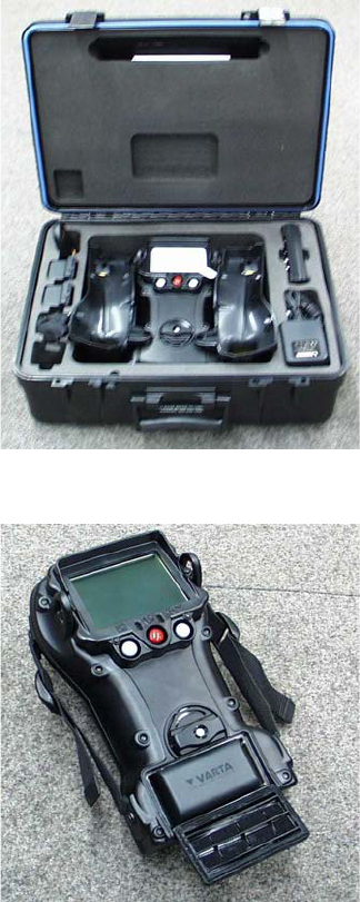
.In the case with this manual you
will find the camera, a pair of
handles, a neckstrap, remote
control, two rechargeable battery
packs, battery charger with mains
and DC leads, two AA battery
packs, customer software and
data lead.
.Check that the rechargeable
batteries are fully charged before
use and the battery packs contain
LR6 type batteries (if supplied).
Open battery door and insert the
battery pack as shown. It will fit in
either rotation. Close the door.
4
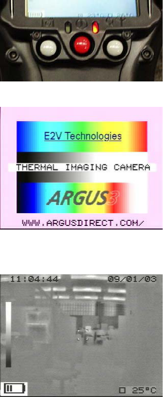
.Turn on the unit using the middle
RED button on the rear. A RED
light will be illuminated in the
position shown. A long (3 second)
press is required to switch the
camera off.
.After switch-on and for
approximately 10 seconds, a
splash screen will be displayed
on the camera screen while the
system performs a self-test
routine. This splash screen is
customer configurable – see
section 5.
.After 10 to 20 seconds
(depending on ambient
temperature and sensor type) the
thermal image, with battery status
display, time and date and
ambient temperature, will
appear. If spot temperature
option is included, the sample
window and spot temperature
will also appear.
5
1.2 DISPLAY GRAPHICS
The camera is equipped with an advanced microprocessor based control and
user warning system. In addition to controlling the automatic operation of the
camera to ensure the best possible picture at all times, the control system
provides graphics on the display to alert the user to certain conditions as follows:
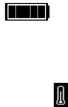
.Battery Status
The battery status indicator is always visible at the lower left side of the display,
except during the start up/self-test routine. See Charger and Battery section for
operation details.
.Over-temperature Warning
As the circuitry within the camera approaches its maximum designed operating
temperature, a warning symbol in the shape of a thermometer will appear to the
right of the battery status indicator. The camera will continue to operate at this
temperature but the user may see some degradation of the image quality.
If the user ignores this warning and continues to operate the camera in very high
temperatures, a flashing temperature warning statement will appear on the
screen.
When the temperature warning statement is present, the camera is very
close to its absolute operating limit and the image will start to degrade
considerably. The user must remove the unit from the high ambient
temperature at this time; failure to comply may result in permanent
damage to the unit.
6

.General System Failure Warning
As part of the operation of the system, the microprocessor monitors certain
functions and displays an internationally recognised warning symbol if it detects
a fault. The warning, which takes the form of an exclamation mark within a
triangle, will appear to the right of the battery status indicator (and to the right
of the temperature warning if this is active). The warning will appear if any of the
following faults are detected:
High humidity within the sealed case assembly.
This will occur if the plastics or the case seal are damaged and allowing
moisture into the camera.
Failure of the lens iris assembly
This warning symbol may appear briefly during normal operation, but the
camera must be returned to an authorised service centre or the factory if the
warning symbol remains on.
Failure to act upon this level of warning may result in serious damage to the
system and may invalidate the warranty.
.Zoom Symbol
The zoom symbol indicates when the 2x zoom function is activated. This will
appear to the right of the battery status indicator.
.Image Capture Symbol
The image capture symbol appears for a short time over the battery status
indicator after the image capture button has been pressed. The screen will also
show which image number out of 26 has been captured.
.Transmitter ON/Channel Number Symbol
When the transmitter is turned on (if fitted), the transmitter ON/channel number
symbol will appear to the right of the battery status indicator.
7
1.3 OPERATING NOTES
.Interpreting The Image - Relative Temperatures
The image displayed is simply a black and white picture of the infrared energy
entering the lens. The camera displays relative temperature differences between
individual objects and their surroundings, irrespective of overall ambient
temperature.
The camera is set up to display objects at various shades, from black for cooler
items to white for hotter bodies, i.e. in a room at 20 8C a cold drink would
appear black whilst a hot radiator would appear white. In a room at 250 8C,
however, it is possible that the same hot radiator may appear darker than, for
example, burning materials.
.Identification of Fire and Hotspots
The camera will represent zones of very high temperature as white zones within
the picture. Very small fires or smouldering material will cause the automatic iris
to close down slightly, but the image of surrounding objects will remain clearly
visible.
.Hidden Fires
It is possible that fires may be burning or smouldering behind doors, in ducting
or indeed in wall or floor cavities. In such circumstances, the operator should
look for areas which appear whiter when compared with the surroundings. For
example, a fire behind a door will cause the door to appear whiter against the
background. Similarly, a white area on an otherwise dark wall could indicate the
area of fire behind the masonry.
8
.Search for Persons and Objects
The camera is not restricted to locating fires. In many cases, the firefighter will be
using the camera in a search for casualties, to seek out dangerous items such as
fuel tanks or gas cylinders and also as an aid to navigation through unknown
premises.
.Image Clarity
The sharpness and clarity of the image provided is related to the temperature of
the scene and objects in view. A cold room provides little infrared energy and
less detail is detected than in a warm environment where objects give off
significant energy. In general, the warmer the scene, the more thermal contrast
and hence greater detail in the picture.
.Heat Layers in Closed Spaces
In a major fire, a layer of hot gases may build up in the upper region of the
closed space. Attempting to use the camera in this hot layer will cause the image
to become featureless. By bringing the camera down beneath this layer, the unit
is able to provide the firefighter with a clearer picture of the scene ahead.
.Windows and Polished Surfaces
Glass is not transparent to long wavelength infrared energy and it is not possible
for the operator to use the camera to look through a window. A white window
would indicate that the window itself is relatively warm and may be being
heated by a fire behind it. Just as we see reflections in glass under normal
circumstances, it is possible that the camera can detect infrared reflections in
glass, mirrors and polished or painted surfaces. Care must be taken to ensure
that the image seen is not simply a reflection. Experience will give the operator
added confidence.
9
.Control of Water Streams/Jets
When viewed through the camera, water streams from hose reels will appear
black against the background scene. The control and aim of water flow can be
monitored by viewing the flow and its effect on the fire through the camera. It
may be necessary, if employing a water wall, to drop the wall momentarily to
view the effects of the extinguishing stream.
.Smoke Types
The camera will provide vision through all types of smoke and steam.
.Lens Cleaning During Operation
The camera lens, like the BA visor, may become obscured during use. The lens
may be cleaned with a glove or cloth if necessary.
10
2 Standard Functions
2.1 IMAGE CAPTURE
.Up to 26 images can be captured and stored in the camera. These images
can then be viewed or deleted using the remote control or software
provided (see section 4 for details of remote control). Using the software
provided, captured images can be downloaded to a suitable laptop/PC in
.bmp format.
.To capture an image press the left-hand button. The image capture symbol
will appear over the battery status indicator and the number of the image
out of 26 will be displayed on the screen.
.If the image capture button is pressed and the camera has 26 images stored,
a warning ‘FULL’ will appear. Before further images can be stored, images
will have to be saved to a laptop/PC or deleted using the remote control or
software provided.
2.2 ZOOM
.The zoom function is operated by a short press on the right-hand button
and is indicated by the magnifying glass icon on the screen.
.Where the temperature measurement option is combined with zoom, the
sample window is also expanded to suit.
2.3 TIME AND DATE
.Time and date is displayed at the top of the screen in the format:
hh:mm dd/mm/yy
.This is also present on the external video feed for recording directly or via the
Video Transmission systems and will be shown on any image captured.
.The date and time can be adjusted using the remote control or software
provided.
11
2.4 AMBIENT TEMPERATURE
.The ambient temperature sensor is fitted to the front of the camera and the
ambient temperature is displayed on the video.
.The range for ambient temperature measurement is 717 8C (1.4 8F) to
150 8C (302 8F). If ambient temperature measurement is not required, it can
be turned off using the software and the readout display will be removed
from the video.
12
3 Optional Functions
3.1 SPOT TEMPERATURE MEASUREMENT
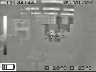
.The addition of a sensor to the
camera allows the operator to
view the average scene
temperature (within a defined
area). The temperature is
displayed as an overlay on the
camera video.
.This system is intended to give the
operator the ability to detect
possible hazards such as hot gas
bottles or tanks. The camera can be configured to give a reading in 8Cor8F
by using the user software (see section 5).
.Scene temperatures between 0 8C (32 8F) and 500 8C (932 8F) can be
displayed. If the temperature lies outside this range a 4or 5symbol
appears before the reading indicating that it is outside the possible range.
Note: If the object in the scene does not fully fill the sample window, then a false
reading may be obtained. Care should be taken not to cover up the sensor
window (with a hand for example) when using this system.
3.2 TRANSMITTER
The transmitter is housed inside the camera and is powered by the camera
battery. It is designed to allow remote viewing of a thermal image from the
camera. To switch on the transmitter, press and hold the transmitter ON button
at the rear of the camera. When the transmitter is turned on, the transmitter on/
channel number symbol will appear to the right of the battery status indicator.
13
The performance of the system will allow a transmitting range of greater than
1 km (0.6 mile) line of sight. This will be reduced when used inside buildings and
will vary depending on the construction of the building and how many walls etc.
are between the camera and the receiver.
Due to the relatively low power of the system and the high frequency used (1.4
or 2.4 GHz) it is normal for the received picture to break up momentarily when
the camera is moved. This break-up is caused by multi-pathing of the signal as it
bounces off objects and people between the camera and the receiver.
The transmitter is available in two frequencies, 1.4 GHz and 2.4 GHz, depending
on the local licensing regulations of the country of use.
.1.4 GHz Transmitter
The transmitter is supplied as a single-channel 200 mW system and is
MPT1349 approved for use in the UK only. The transmitter should be used in
conjunction with the Receiver Kit DAS548076AA or the Receiver Case.
.2.4 GHz Transmitter
The transmitter is supplied as a two-channel 300 mW system and is FCC part
90 approved for use in the US. The transmitter should be used in
conjunction with the Receiver Kit DAS547874AA or the Receiver Case.
3.3 RECEIVER KITS
Both the receiver kits provide a standard 1.0 V video output and are designed for
use with a separate video monitor (not supplied). The receiver requires 12 V dc
power, either from a vehicle supply or the mains adaptor supplied. The antenna
can be mounted on a pole if required and is connected to the receiver by a 3 m
(10 ft) long cable.
14
Mount the antenna in a suitable location, so that the front of the unit is directed
towards the camera is deployed. Connect the antenna to the receiver using the
cable provided. Connect the DC power to the receiver using the mains adaptor
provided. Connect the receiver to a suitable video monitor using the phono or
BNC connector located on the rear of the unit.
.Receiver kits for 1.4GHz transmitters (DAS548076AA)
The stand-alone receiver is single-channel and is supplied complete with
high gain antenna (DAS549406AA). Also supllied is an antenna to receiver
cable (DAS548241AA) and mains adaptor unit (DAS548235AA).
.Receiver kits for 2.4GHz transmitters (DAS547874AA)
The stand-alone receiver has two channels and is supplied complete with
high gain antenna (DAS547875AA). Also supplied is an antenna to receiver
cable (DAS548236AA) and mains adaptor unit (DAS548235AA).
15
4 Remote Control Functions
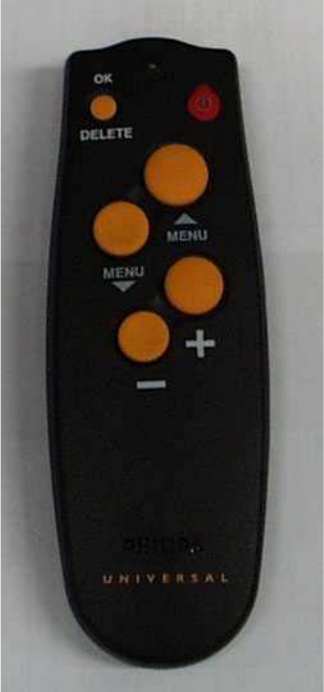
To access the remote control functions, press the RED button on the remote. The
screen will show the first of the list of 8 options. These are:
Brightness Adjustment,
Contrast Adjustment,
Colour Adjustment,
Transmitter Channel,
Colour Options,
White Hot or Black Hot,
Stored Image: Review and Deletion,
Time and Date Setting.
To access any of these functions press
the menu ~or menu !buttons
until the desired option is displayed.
Once the desired option has been
selected, each option has further
action (see below). Pressing the RED
button again will set any changes
required and leave the option list or,
pressing the menu ~or menu !
buttons, another option can be
selected.
.Brightness, Contrast and Colour
Adjustment
By pressing the + or 7buttons,
the brightness, contrast and colour of the LCD screen is increased or
reduced.
.Transmitter Channel
By pressing the + or 7buttons, the transmitter channel is selected.
16
.Colour Options
By pressing the + or 7buttons, the colour options can be scrolled through.
These are:
Grey Scale Half Colour
Green Scale Full Colour 1
Red Spot Full Colour 2
Soft Red Spot Full Colour 3
.White Hot or Black Hot
By pressing the + or 7buttons, white hot or black hot can be selected.
.Stored Image: Review and Deletion
Review
By pressing the + or 7buttons, the stored images can be scrolled through.
Deletion
By pressing the + or 7buttons, the stored images can be scrolled through
until image required to be deleted is selected. Press the delete button twice
to delete image.
.Time and Date Setting
Press the OK button to enter the time and date settings. Using the menu ~
or menu !buttons, scroll through the hours, minutes, days, months and
years. Adjust each setting as required by using the + or 7buttons. Once
the desired setting has been achieved, scroll to save time and date and press
OK.
17
5 Software
Using the camera data port and cable provided, a number of the camera
functions can be set, enabled and adjusted by the user from a standard laptop/
PC. The software is supplied on CD-ROM in the back of this manual. The
software allows the user to:
Download stored images.
Upload splash screens.
Set, enable or disable time and date.
Use, enable or disable the zoom function.
Set, enable or disable temperature display and units.
Set white or black hot and colour options.
Enable or disable the transmitter and select channel (if option is fitted).
To change the camera settings, connect the interface lead 9-way D socket to the
laptop/PC serial port. If the PC serial port has 25 pins, an adaptor will be
required. Plug the interface lead 5-pin round plug into the camera data port.
.Operating Systems
The Argus
1
3 customer software supports the following operating systems:
Windows
1
NT (all versions).
Windows
1
2000 service pack 3 or newer.
Windows
1
XP (all versions).
If the laptop/PC is running Windows
1
95, 98 or ME, the Argus
1
3 software will
run and install but can have some problems with older versions. As Microsoft no
longer supports these operating systems, e2v technologies cannot provide full
support for them.
If the laptop/PC is running Windows
1
2000 with an unsupported service pack,
visit the Windows
1
update web page at http://v4.windowsupdate.microsoft.com/
en/default.asp. Click on the search button and insert the service pack update
required. Follow the on-screen information.
.Installing the Software
Insert the Argus
1
3 Information CD into the CD drive of the laptop/PC. After a
short time the CD will autostart and open up the main page of the Argus
1
3
Information CD. If the CD does not autostart, the main page can be viewed by
opening local file D:\index.htm in a web browser (replace ’D’ with the drive letter
of the CD-ROM drive if necessary).
18
To install the software, click ’Install Software’ on the main page. This will open
the software page; click ’install software’. A box will appear, asking to copy or to
run the software from its current location. Click ‘run from current location’, then
click ‘OK’. Another box will appear; click ‘Yes’ to install the software. A box will
now appear to update the systems files. When the box disappears, another will
pop up; click ‘OK’ to the installation. Immediately after, there will be a prompt to
restart the system before starting a full installation. Click ‘Yes’ to restart system.
Once the restart has been completed, install the software again.
After clicking ‘install software’ for the second time, click ‘OK’ to the installation.
If the installation is an older version than the current one on the laptop/PC, there
may be a prompt to keep any .OCK or .DLL files; click ‘Yes’. Click ‘OK’ to the
successful completion to the installation.
The software should now be correctly installed. To run the Argus
1
3 software,
click on ‘Start’, find the Argus
1
3 software title under Programs, then click the
Argus
1
3 customer software.
The software can be installed by running D:\setup.exe (replace ’D’ with the drive
letter for the CD-ROM drive if necessary). Follow the on-screen commands and
the above procedure.
.Using the Software
Power up the camera and wait
until a thermal image has
appeared on the camera screen.
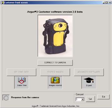
Connect the data cable between
the camera and laptop/PC. Start
the customer sofware and wait
until the test software front screen
opens. Click connect to camera.
If the connection to the camera
has been successful, connect to
camera will disappear and three
options will be available:
Set Time and Date.
Stored Images.
Advanced Software.
19
If the connection to the camera is unsuccessful, exit from the software by
clicking exit. Start the customer sofware and wait until the test software front
screen opens. Using the com port drop-down menu, set the com port to 2 and
click set. Click connect to camera. If the connection to the camera is still
unsuccessful, check all the leads are firmly home.
.Set Time and Date
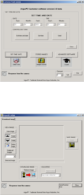
Open up the software and click
set time and date.Anew
window will open. This area
allows the user to set the time
and date. To set the time and date,
click get time from the PC, then
click send. This will set the camera
to the time and date as per the
laptop/PC.
If this time or date is incorrect,
click edit time and date and from
the drop-down menus for hours,
minutes, day, month and year
select the correct time and date and click send.
Once complete, click close to return to the software front screen. Click exit to
close the software.
.Stored Images
Open up the software and click
stored image. This area allows the
end-user to download stored
images from the camera.
View Images Frame
This area allows the end-user to
view or delete images from the
camera.
20
View Image:
Click view image and the camera will show its first stored image on the LCD
screen. To view each image, click next image or previous image to scroll
through each image. Alternatively, from the drop-down menu, select the
number of the image to be viewed. When viewing is complete, click display
scene to return the camera to its normal operation.
Delete Image:
Select the image to be deleted via View Image (above). Once selected, click
delete image. That image will be deleted. Alternatively, click delete all
images to clear all images from the camera. When deletion is complete, click
display scene to return the camera to its normal operation.
Download Image Frame
This area allows the end-user to retrieve images from the camera.
Select the image to be retrieved via View Image (above). Once selected, click
retrieve image. The software will show an increasing time elapse bar and the
camera screen will blank with the message ’transferring image’. On completion
of retrieval, a prompt will appear to inform that the image must be saved.
At this point it is advisable to save the image in its grey scale format.
Save Image Frame
This area allows the end-user to save any retrieved images from the camera. To
save the image, click save. A new window will open. Select the folder the image
is to be saved in and click save.
Colorise
This area allows the end-user to colorise any retrieved images from the camera.
The retrieved image can now be colorised to any of the standard colours of the
camera and also shown in black or white hot, by using the drop-down menu.
Once complete, click close to return to the software front screen. Click exit to
close the software.
21
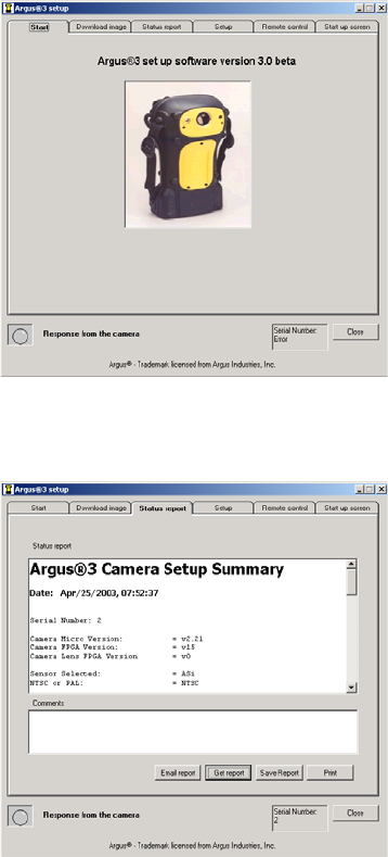
.Advanced Software
Open up the software and click
advanced software.Thereare
five options available:
Download Images.
Status Report.
Set-up.
Remote Control.
Start-up Screen.
Download Images Tab
See Stored Images (above) for
further information.
Status Report Tab
Open up the software and click
the Status Report tab. This area
allows the end-user to interrogate
the camera and enable a fault
diagnosis of the camera. Click get
report and a refreshed status
report will be retrieved.
To save the report, click save
report and a new window will
open. Select the folder the report
is to be saved in and click save.
To print the report, click print and
a new window will open. Click print.
The report can be emailed to the e2v technologies Service Centre. If the laptop/
PC has a compatible email facility, click email report. This will automatically
send the report. If the laptop/PC is not compatible, save the report as above and
attach this document to any other type of email. The email address is
argus3.repaircentre@e2vtechnologies.com. The comments box allows the
end-user to add any further information about the camera. This will
automatically be saved, printed or emailed with the report.
22
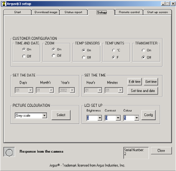
Setup Tab
Open up the software and click
the Setup tab. This area allows the
end-user to enable, disable, select
and set up various functions on
the camera. When the tab is
initially pressed, the settings of
the camera attached to the
laptop/PC will be shown.
Customer Configuration Frame
These two area allow the end-user
to configure various functions of the camera. These are:
Time and date enable/disable; check as required.
Zoom enable/disable; check as required.
Temperature sensors enable/disable; check as required.
Select Celsius or Fahrenheit; check as required.
Select Black or White Hot; check as required.
Temperature Colour Bar enable/disable; check as required.
On-Screen Graphics in or out (see note); check as required.
Transmitter enable/disable; check as required.
Note: The graphics in/out function is only necessary if the graphics are unable to
be seen when using an external monitor.
Picture Colouration Frame
This area allows the user to select the colour option for the camera screen. From
the drop-down menu, select the required colouration and click select.
LCD Set-up Frame
This area allows the user to select the LCD brightness, contrast and colour levels
for the camera screen. From the drop-down menu, select the required level and
click config.
23
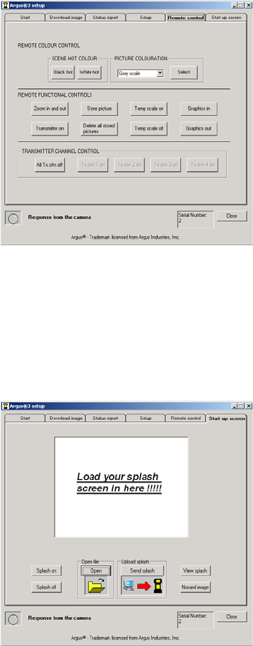
Remote Control Tab
Open up the software and click
the Remote control tab. This area
allows the end-user to perform
various functions of the camera
remotely via a laptop/PC.
Zoom In and Out Button:
Allows the end-user to zoom
the camera in or out.
Store Picture Button:
Allows the end-user to store an
image.
Transmitter Channel Control
This area allows the user to select the transmitter channel and by doing so turns
on the transmitter. Only the channels avaliable will be highlighted. To turn off
the transmitter, click all tx chn off.
Uploading Splash Screen Tab
Open up the software and click
the Setup tab. This area allows the
user to upload a splash screen of
their choice to the camera.
To upload an end-user splash
screen, the image to be uploaded
must be a 320 x 240 pixel bitmap.
Click open and a new window will
open. Select the folder the image
is saved in and click open. The
selected image will appear in the
image window.
If this is correct, click send splash. Once the upload has been completed, turn
the camera off and then on again and check the selected image is the splash
screen.
24
If an end-user splash screen is no longer required, click splash off to return to the
e2v technologies splash screen. Click splash on to return to the uploaded splash
screen.
To view the splash screen stored in the camera, click view splash. Click normal
image to return to the normal image.
Once complete, click close to return to the software front screen. Click exit to
close the software.
25
6
Cleaning, Maintenance and
Replacement Parts
.Cleaning
After use and prior to stowing, the camera should be cleaned. This is best carried
out using a cloth soaked with warm soapy water. Solvents should not be used.
If in doubt, contact your supplier.
.Maintenance
No routine maintenance is required for the camera. If it is not in regular use, it
should be switched on for 10 minutes every month to check correct operation.
.Replacement Parts
Due to the environment in which the camera is used, the user can replace certain
parts. If any damage beyond these parts occurs, return the camera to e2v
technologies or an authorised repair centre.
Any attempt at repair by unauthorised personnel may cause serious damage and
will invalidate the warranty. THERE ARE NO OTHER USER-SERVICEABLE
PARTS.
Handles (state colour when ordering)
Left Handle:
DAS701201AA (Blue)
DAS701201BA (Orange)
DAS701201CA (Yellow)
Right Handle:
DAS701202AA (Blue)
DAS701202BA (Orange)
DAS701202CA (Yellow)
26
To replace the handles, remove all screws using a 2 mm hex key. Remove the
handles and discard the screws, as replacements will be supplied. Replacement
is the reverse of removal.
Bumpers
Left Bumper: DPP701141AA.
Right Bumper: DPP701142AA.
The bumpers are supplied without side straps (see below for details). To replace
the bumpers, remove the screws using a 2 mm hex key. Remove the crosshead
screws, remove the side straps from the bumpers and discard the screws, as
replacements will be supplied. Replacement is the reverse of removal.
Side Straps DAS542693AA
To replace the side straps, remove the screws holding the bumpers to the
camera using a 2 mm hex key. Remove the crosshead screws and remove the
side straps from the bumpers. Replacement is the reverse of removal.
Lens Bezel (state colour when ordering)
DAS701204AA (Blue)
DAS701204BA (Orange)
DAS701204CA (Yellow)
To replace the lens bezel, remove all screws using a 2 mm hex key. Remove the
lens bezel and discard the screws, as replacements will be supplied. Replacement
is the reverse of removal.
27
Access Panel (state colour when ordering)
DAS701205AA (Blue)
DAS701205BA (Orange)
DAS701205CA (Yellow)
To replace the access panel, remove all screws using a 2 mm hex key. Remove the
access panel and discard the screws, as replacements will be supplied.
Replacement is the reverse of removal.
Other spares and accessories.
Neck Strap DAS701207AA
Battery Pack DAS701210AA
Rechargeable Battery Pack E100173
Charger Unit – Country dependent; ask for details
Remote Control DAS702007AA
RS232 Computer Lead DAS546769AA
User Manual and CD-ROM DAS702198AA
Camera Carry Case DAS701420AA
28
7 Specifications
.Mechanical
Dimensions . 162 x 271 x 122 mm (W x H x D) nominal (without handles)
300 x 271 x 122 mm (W x H x D) nominal (with handles)
Weight ........2.1kgnominal (including batteries and handles)
Case material .................. Radel
1
R-5100
Lens bezel material ....Radel
1
R-5100 over-moulded in Santoprene
1
Access panel material . . . Radel
1
R-5100 over-moulded in Santoprene
1
Neck strap ......................Nomex
1
Side straps .....................Nomex
1
.Electrical
Power supply ................ integral battery pack
Power consumption .....5Wnominal (dependent on options fitted)
Battery ...... Ni-MH rechargeable pack or 8 AA/LR6 type batteries
Battery life .......... 42 hours typical continuous operation
.Optical – BST
Sensor .............. BariumStrontium Titanate (BST)
Detector type ...............focal plane array (FPA)
Pixel count .................... 320x240
Lens ........purposed-designed, three-element germanium lens
Field of view ...................508horizontal
Depth of field ................. 1to30metres
Aperture ....................... f/1.0
Spectral response .................. 8–14mm
Iris ....................... automatic
NETD .......................50.1 8C
29
.Optical – ASi
Sensor ................. Amorphous Silicon (ASi)
Detector type ................. micro-bolometer
Pixel count .....................160x120
Lens ...........germanium lens as supplied with detector
Field of view .................. 508horizontal
Depth of field ..................1to30metres
Aperture ........................f/1.0
Spectral response ..................7–14mm
NETD ....................... 50.1 8C
.Environmental
High temperature tolerance . . the camera will withstand 60 8C (140 8F) for
1 hour minimum and 150 8C (302 8F) for 10 minutes
Low temperature tolerance .... rechargeable batteries 710 8C (14 8F)
AA batteries 5 8C (41 8F)
Storage temperature .........710 to +50 8C (14 to 122 8F)
Sealing ........ dust and water proof to EN 60529, class IP67
Mechanical stability .........tested against shock and vibration
Drop .......... will withstand a drop of 1 metre (3.28 feet)
EMC ................ asperdirective 89/336/EEC
.Other
Viewing ............. 100mm(4-inch) full colour LCD
Video output .....BNCplug behind access panel for 75 O1 V video
Image capture ........... upto26imagescanbecaptured
Computer connection ........... viaRS232 lead (supplied)
Carrying mode .... hand straps fitted, handles and neck strap supplied
Operation .......... single button on/off, with delayed off
Storage ......... carrying case for camera, batteries, charger,
neck strap and user manual
Service .............. Periodic service is not required
Repairs ..... bymanufacturer or authorised local service centre only
30
8 Battery and Charger
8.1 BATTERY
The Argus
1
3 camera is supplied with both rechargeable and primary battery
packs. All battery packs provide an output to the battery status bar on the
Argus
1
3 camera. This bar provides a continuous indication of the remaining
charge, allowing the firefighter to avoid unpredicted power loss.
With a fully recharged battery, or a battery pack fitted with new batteries, the
battery status bar will be at its full status with 5 bars showing. With high quality
batteries or the condition of the rechargeable pack, it may remain at this height
for some minutes. The number of bars will then progressively decrease as the
batteries discharge. When the battery status bar has reached 2 bars, there is
approximately one (1) hour of battery life remaining.
When the battery is low, a ‘LOW BATTERY’ warning will appear over the battery
status bar to alert the operator. The time remaining will depend on the type of
batteries being used, but will typically be 10 minutes.
Note: Before each BA team enters the fire, it is recommended that the camera is
used with a rechargeable battery at full charge or a battery pack fitted with new
batteries.
Rechargeable Battery Pack
The Argus
1
3 uses a readily avaliable camcorder-style Nickel Metal Hydride (Ni-
MH) rechargeable battery pack. The type supplied is a Varta V217 6 V 3600 mAh
but other variants are avaliable. The rechargeable packs are designed to power
an Argus
1
3 camera for over 2 hours from a full charge, dependent on options
fitted. Before using the battery, read the leaflet supplied with this manual.
Note: Disposal of batteries should be in line with their manufacturers’
instructions.
31
Primary Battery Pack
Primary batteries are suitable for ocassional or back-up use. The primary packs
are designed to power an Argus
1
3 camera for over 1.5 hours if fitted with new
batteries. The batteries used in the primary battery pack are AA size.
It is recommended that type LR6 batteries be used, as these are essential to
achieve the specified battery life. LR6 indicates an alkaline manganese battery,
which can supply the power requirements of the Argus
1
3. Labels such as ’long
life’ or ’super power’ are manufacturers’ titles and do not necessarily imply LR6.
It recommended that all 8 batteries in a set be changed simultaneously.
The operating life of LR6 batteries varies greatly between manufacturers and is
temperature dependent. e2v technologies recommend the use of rechargeable
systems at ambient temperatures of 5 8C (41 8F) or less.
Battery replacement
Open the pack by pressing the two clips inwards and pulling. Remove the old
batteries and dispose of them safely. Insert new batteries in the correct
orientation shown on the inner carrier. In order to verify the pack is ready for
use it may be tried in the camera.
Note: Disposal of batteries should be in line with their manufacturers’
instructions.
8.2 BATTERY CHARGER
The Argus
1
3 uses a readily avaliable camcorder-style Battery Charger. The type
supplied is dependent on location, but other variants are avaliable. The battery
charger can be powered by either AC mains or 12 V DC and all cables are
supplied. Before using the battery charger, read the leaflet supplied with this
manual.
32
9 Warranty Terms
9.1 EXPRESS WARRANTY
e2v Technologies ("e2v") warrants that this product is free from mechanical
defects or faulty workmanship for two (2) years from the date of shipment, with
the exception that the warranty period for the battery charger and for the
rechargeable battery pack is one (1) year from that date, provided it is
maintained and used in accordance with e2v’s instructions and/or
recommendations.
This warranty does not apply to expendable or consumable parts whose normal
life expectancy is less than one (1) year. Replacement parts and repairs are
warranted for ninety (90) days from the date of shipment.
e2v shall be released from all obligations under this warranty in the event repairs
or modifications are made by persons other than its own or authorised service
personnel or if the warranty claim results from misuse of the product. No agent,
employee or representative of e2v may bind e2v to any affirmation,
representation or modification of this warranty concerning the goods sold
under this contract.
THIS WARRANTY IS IN LIEU OF ALL OTHER WARRANTIES, EXPRESS,
IMPLIED OR STATUTORY, AND IS STRICTLY LIMITED TO THE TERMS
HEREOF. e2v SPECIFICALLY DISCLAIMS ANY WARRANTY OF
MERCHANTABILITY OR OF FITNESS FOR A PARTICULAR PURPOSE.
33
9.2 EXCLUSIVE REMEDY
It is expressly agreed that the Purchaser’s sole and exclusive remedy for breach of
the above warranty, for any tortious conduct of e2v, or for any other cause of
action, shall be the repair and/or replacement, at e2v’s option, of any equipment
or parts thereof, that after examination by e2v are proven to be defective.
Replacement equipment and/or parts will be provided at no cost to the
purchaser, F.O.B. e2v’s plant. Failure of e2v to successfully repair any non-
conforming product shall not cause the remedy established hereby to fail of its
essential purpose.
9.3 EXCLUSION OF CONSEQUENTIAL DAMAGES
PURCHASER SPECIFICALLY UNDERSTANDS AND AGREES THAT UNDER NO
CIRCUMSTANCES WILL e2v BE LIABLE TO PURCHASER FOR ECONOMIC,
SPECIAL, INCIDENTAL OR CONSEQUENTIAL DAMAGES OR LOSSES OF
ANY KIND WHATSOEVER INCLUDING, BUT NOT LIMITED TO, LOSS OF
ANTICIPATED PROFITS AND ANY OTHER LOSS CAUSED BY REASON OF
THE NON-OPERATION OF THE GOODS. THIS EXCLUSION IS APPLICABLE
TO CLAIMS FOR BREACH OF WARRANTY, TORTIOUS CONDUCT OR ANY
OTHER CAUSE OF ACTION AGAINST e2v.
34
In the event of a warranty failure, return your camera to your local Argus
1
sales
centre:
USA
The Argus
1
sales team
e2v technologies inc.
4 Westchester Plaza
Elmsford
NY 10523-1482
Tel (toll free): 1 800 342 5338
Fax: (914) 592 5148
E-mail: argusdirect@e2vtechnologies.com
France
Philippe Silvestre
e2v technologies sas
16 Burospace
91572 Bie`vres Cedex
Tel: +33 (0) 16019 5580
Fax: +33 (0) 16019 5529
E-mail: argusdirect@e2vtechnologies.com
Web site: www.argusdirect.com
UK and Rest of the World
The Argus
1
sales team
e2v technologies
106 Waterhouse Lane
Chelmsford
Essex CM1 2QU
England
Tel: +44 (0) 1245 453443
Fax: +44 (0) 1245 453725
E-mail: argusdirect@e2vtechnologies.com
Printed in England
35