EBR Systems 5100 Model 5100 Programmer User Manual Users manual
EBR Systems Inc Model 5100 Programmer Users manual
Users manual

WiSE™ CRT System
INSTRUCTIONS FOR USE
Programmer Model 5100
Software Release 6
For use with:
• WiSE CRT Transmitter Model 4000, Software Release 3
• WiSE CRT Transmitter Model 4100, Software Release 1
EBR Systems, Inc.
480 Oakmead Parkway
Sunnyvale, CA 94085 USA
www.ebrsystemsinc.com
+1 408 720 1906
support@ebrsystemsinc.com
Premier Research Group Limited
1st Floor, Rubra 2, Mulberry Business Park
Fishponds Road, WOKINGHAM
Berkshire, RG41 2GY, United Kingdom
Australian Sponsor:
EBR SYSTEMS, INC. PTY. LIMITED
LELEL 21, 133 CASTLEREAGH STREET
SYDNEY, NSW, 2000
LBL-03843-EN Rev. A2

WiSE CRT System Programmer Model 5100 Instructions for Use 1
Table of Contents
1 Precautions ........................................................................................................................................... 2
1.1 Storage and Handling .................................................................................................................... 2
1.2 Co-Implanted Pacemaker and Defibrillator Compatibility ............................................................ 2
1.3 Programming ................................................................................................................................ 2
1.4 Environmental Interference .......................................................................................................... 2
2 WiSE CRT System Programmer ............................................................................................................. 3
2.1 Using the Programmer .................................................................................................................. 3
2.1.1 Configuring Connections to the Radio Module and the Tablet Computer .............................................. 4
2.1.2 Turning the Programmer On/Off ............................................................................................................. 4
2.1.3 Using the Touch Screen for Selection ...................................................................................................... 5
2.1.4 Navigating with the Main Menu .............................................................................................................. 6
2.1.5 Programmer Setup ................................................................................................................................... 7
2.2 Establishing a Communication Session with a Pulse Generator ................................................... 8
2.2.1 Programmer Status Bar............................................................................................................................ 9
2.2.2 Pulse Generator Status Bar ...................................................................................................................... 9
2.3 Reviewing and Printing Device Data ........................................................................................... 10
2.4 Programming Permanent Pulse Generator Parameters ............................................................. 11
2.5 Patient Information and Device Tracking ................................................................................... 12
2.6 Test and Evaluation Tools ........................................................................................................... 13
2.6.1 Initializing Synchronization with the Co-Implant ................................................................................... 13
2.6.2 Set-Up the Alignment of the Transmitter Model 4000 with the Acoustic Window .............................. 15
2.6.3 Set-Up the Alignment of the Transmitter Model 4100 with the Acoustic Window .............................. 18
2.6.4 Transmitter Model 4100 Speaker Test for Battery ................................................................................ 20
2.6.5 Initiating Temporary LVOO Mode .......................................................................................................... 21
3 System Evaluation during Implant and Follow-up .............................................................................. 22
3.1 Initializing the System ................................................................................................................. 22
3.2 Battery Model Selection ............................................................................................................. 22
3.3 Battery Status and End of Service ............................................................................................... 23
3.4 Battery Longevity ........................................................................................................................ 24
3.5 Using Marker Events ................................................................................................................... 25
3.6 Troubleshooting .......................................................................................................................... 26
4 Technical Specifications ...................................................................................................................... 29
4.1 Physical and Electrical Specifications .......................................................................................... 29
4.2 Parameter Specifications ............................................................................................................ 29
4.3 Programable Pulse Generator Values ......................................................................................... 30
4.4 Technical Service and Support .................................................................................................... 30
4.5 Cleaning and Disposal of Devices ................................................................................................ 30
4.6 EMC Information ......................................................................................................................... 31
5 Symbol Glossary .................................................................................................................................. 32

2 WiSE CRT System Programmer Model 5100 Instructions for Use
1 PRECAUTIONS
PRECAUTION - For use only by Qualified Medical Personnel in professional healthcare environments: The
WiSE CRT System Programmer is intended to be used by qualified physicians and medical technicians. The
Programmer is only to be used in professional healthcare facilities. EBR Systems provides hands-on pre-clinical
training. Before using the system, contact EBR Systems to schedule a two-hour training session for Programmer
operators. At least annually, review didactic training materials supplied and presented by support personnel
from EBR Systems. Obtaining this training prior to using the Programmer is a responsibility of the operator. The
information provided in these Instructions for Use and in the WiSE CRT System Instructions for use (LBL-02744)
should be considered as a required supplement for qualified and experienced medical professionals.
1.1 STORAGE AND HANDLING
• Devices should be stored in their original packages in a dry, clean temperature-monitored
environment.
1.2 CO-IMPLANTED PACEMAKER AND DEFIBRILLATOR COMPATIBILITY
• The WiSE CRT System is intended to be used to provide bi-ventricular pacing in conjunction with a co-
implanted pacemaker or defibrillator. Program the co-implanted pacemaker or defibrillator to deliver
right ventricular pacing with the appropriate mode and timing interval settings as would be required
for CRT; e.g. typically a dual chamber pacing modality that utilizes right atrial pacing unless the patient
is in permanent atrial fibrillation.
1.3 PROGRAMMING
• Use only the Programmer Model 5100 to attempt to communicate and program the WiSE CRT System.
• The Programmer Model 5100 is only intended to be used in a professional healthcare environment.
• Program the parameters of the co-implant device to appropriate settings to achieve bi-ventricular
pacing. Do not attempt to program the co-implant pacemaker or defibrillator and the WiSE CRT System
to an LV-only pacing operation.
• Check parameter settings and appropriate system operation on a regular basis, performing a patient
follow-up at least every 3 months.
• Use only the AC power adapter provided with the Programmer to maintain electrical safety.
• If it is necessary to isolate the Programmer from the mains power, remove the power cord from the
external supply module.
1.4 ENVIRONMENTAL INTERFERENCE
• Medical electrical equipment needs special precautions regarding electro-magnetic compatibility (EMC)
and needs to be installed and put into service according to the EMC information provided in these
Instructions for Use.
• The use of accessories or cables other than those supplied with the Programmer Model 5100 may
result in increased emissions of or decreased immunity to electromagnetic interference

WiSE CRT System Programmer Model 5100 Instructions for Use 3
2 WISE CRT SYSTEM PROGRAMMER
The WiSE CRT System has programmable parameters and settings that are adjustable in the Pulse Generator
Transmitters Model 4000 and Model 4100 using the Programmer Model 5100 with a compatible software release.
Delivery of Cardiac Resynchronization Therapy relies extensively on the settings of the co-implanted pacemaker or
defibrillator for the pacing mode, pacing rate, tracking intervals, etc. The WiSE CRT System depends on sensing the
right ventricular pacing electrical output of the co-implant and immediately triggering an ultrasonic transmission to
activate the Electrode in the LV to provide bi-ventricular pacing for CRT. The WiSE CRT System has a minimal set of
programmable parameters. These parameters are used to ensure adequate sensing of the right ventricular pacing
output of the co-implant and to optimize the ultrasound transducer transmission to efficiently use energy from a
WiSE CRT Battery.
The Programmer is packaged in a case containing the following:
1. Model 5100 radio module with an integrated USB cable for connection to the tablet computer (REF:
Model 5100 COM).
2. Model 5100 tablet computer (REF: Model 5100 TAB).
3. An AC power adapter, with country-specific power cord.
4. A recording system connection cable for connecting analog output signals for Marker Events.
5. A copy of these Programmer Model 5100 Instructions for Use and the WiSE-CRT System Instructions for
Use.
2.1 USING THE PROGRAMMER
The Programmer and Pulse Generator communicate using a standard radiofrequency protocol referred to as the
Medical Implant Communications Service (MICS) or MedRadio. This is an ultra-low power radio link that supports
transmitting data for diagnostic or therapeutic operation of implantable medical devices. This communication
standard has been integrated into the WiSE CRT System.
No magnet is required to establish a communication connection between the Programmer and the implanted
Pulse Generator. Communication can be established by the Programmer scanning the immediate vicinity for Pulse
Generators. The Programmer can only establish a connection with WiSE CRT devices. Additionally, no other
devices using the MICS protocol can establish communications with the WiSE CRT Programmer.
IMPORTANT! The Programmer’s radio module should be placed on a flat surface within 2 meters (6 feet) of the
patient in order to establish sufficient communication signal strength between the Programmer and the Pulse
Generator. Move the radio module closer to the patient to improve signal strength. In some circumstances the
radio module may have trouble establishing a link with a Pulse Generator, change position and orientation of the
radio module until a link is established.
IMPORTANT! Position the Programmer Tablet such that the power connections are accessible.
IMPORTANT! Do not touch patient and equipment at same time.
4 WiSE CRT System Programmer Model 5100 Instructions for Use
2.1.1 Configuring Connections to the Radio Module and the Tablet Computer
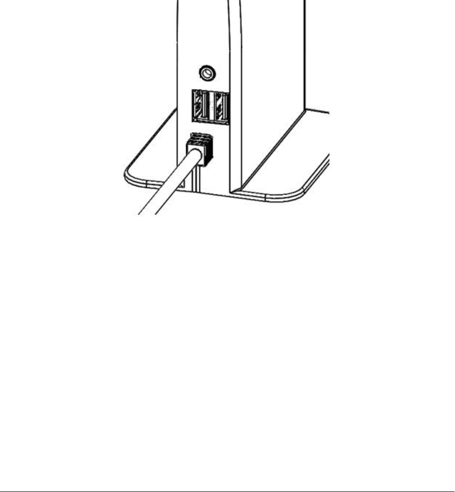
The radio module has an integrated USB-based cable for connecting to the tablet computer. The radio module
also has a connection for analog outputs for Marker Events and contains two USB ports for the use of memory
modules (Figure 1). Printed reports can be sent directly to the USB memory modules connected to this port.
IMPORTANT! Use only USB memory modules with the radio module. Do not connect any other USB devices to the
radio module.
IMPORTANT! Use only the Marker cable supplied by EBR with the Marker Events port. Do not connect any other
cables or devices to this port.
Figure 1: Radio Module Connection Panel
The radio module connections are located on one side of the device.
The tablet computer has a DC input power cable. The cable and the DC converter are supplied with the
Programmer.
IMPORTANT! Use only the AC power adapter provided with the Programmer to maintain electrical safety.
2.1.2 Turning the Programmer On/Off
The Programmer’s computer tablet is powered from an integrated battery or by connecting the tablet to AC line
power using the DC power supply. The radio module is powered from the tablet computer via the USB connection.
The Programmer is powered ON from a switch on the upper right hand side of the tablet computer. The
Programmer is powered OFF/shutdown using an on-screen selection button (Figure 2).
To turn the Programmer ON, press and hold the power switch until the green light within the power-on switch
remains on. . The hardware and software will take 75-90 seconds to initialize. The display indicates that the start-
up process is active until the first application screen appears. When a successful communication between the
tablet computer and the radio module is established a solid blue indicator light on the radio module will illuminate.

WiSE CRT System Programmer Model 5100 Instructions for Use 5
The Programmer may also be turned OFF using the power switch. Press and hold the switch for at least 6 seconds
and then release the switch. The Programmer will then turn off automatically and the green light within the
power-on switch will be extinguished.
Figure 2: Programmer Menu
Located on the left side of the display screen
To turn the Programmer OFF, first select the [SHUTDOWN] button on the Main Menu and confirm the shutdown
selection in the pop-up dialog box by selecting the [OK] button. The Programmer will then turn off automatically.
The power-on indicator will remain illuminated for a short while after the screen darkens. Wait until the indicator
is off before pressing the ON switch again.
The Programmer will display a Shutdown Confirmation or Disconnect Confirmation dialog box (Figure 3). If the
Pulse Generator has been programmed to an OFF or SENSE ONLY mode setting, then this dialog will notify the
operator that the operational setting is not programmed to pace. If the Pulse Generator has been programmed to
the RV Synchronous mode, then the Transmit Level and Pulse Width will be shown in the dialog box.
Figure 3: Disconnect Confirmation Dialog Box
2.1.3 Using the Touch Screen for Selection
User selections on the Programmer are made on a touch-screen display. Selectable areas of the screen appear as
labeled graphic buttons, icons, scrolling up/down arrow buttons, selectable list items, or text entry areas.
Buttons, icons, list items, and active screen areas for text entry can be activated by touching the screen with a
finger. With each successful button contact an audible sound is produced to further discern the response. A
“click” sound indicates the button action has been initiated. A “boop” sound indicates that the button action has
not been initiated and an error has occurred in the selection of the button.
Buttons that indicate the current active selection are highlighted in blue. Buttons are selectable (active) if they are
highlighted in dark gray. Buttons are not selectable if they are shown in light gray. The [PROGRAM] button is an
exception when it is active; it is always displayed in an orange color. On-screen values that are displayed in blue or
orange are transferred to the Pulse Generator when the [PROGRAM] button is selected.
6 WiSE CRT System Programmer Model 5100 Instructions for Use
2.1.4 Navigating with the Main Menu
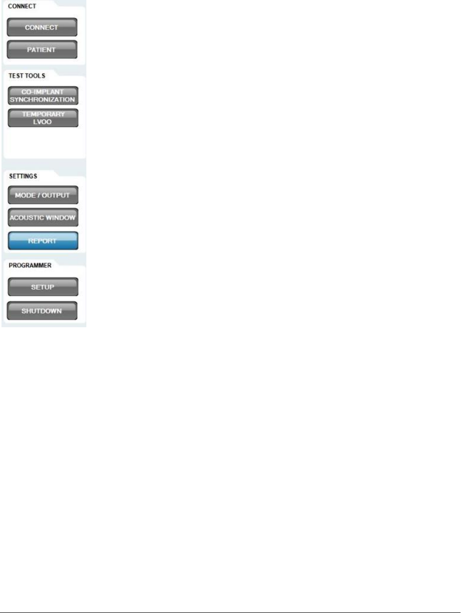
The Main Menu is located along the left side of the display screen (Figure 4).
←
Search for/Connect to Pulse Generators within radio range or
disconnect from currently connected Pulse Generator
←
Store patient and device information in the Pulse Generator
←
Initialize the Pulse Generator for sensing RV pacing spikes
←
Perform temporary asynchronous pacing in the LV
←
Select and program Pulse Generator pacing parameters
←
Align the Transmitter within the acoustic window
←
View and print data and settings of the Pulse Generator
←
Configure the Programmer e.g. Marker Event outputs
←
Turn off the Programmer
Figure 4: Main Menu
Located on the left side of the display screen
WiSE CRT System Programmer Model 5100 Instructions for Use 7
2.1.5 Programmer Setup
Figure 5: Programmer Setup Screen
Accessible by pressing the [SETUP] button from the main menu (Figure 4)
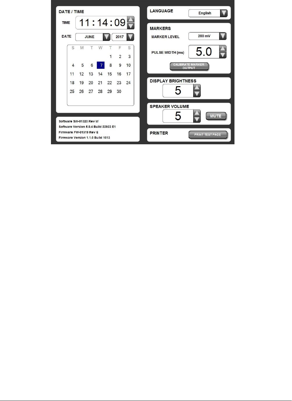
Programmer setup can be accomplished via the Programmer Setup Screen (Figure 5).
The time and date are adjusted by selecting the associated buttons.
By selecting the associated buttons the local language for the buttons and messages, the brightness of the display,
and the volume level of the Programmer’s speaker may be adjusted.
The analog outputs for the Marker Events are adjusted by selecting the associated buttons. To test the Marker
Events output levels, select the [CALIBRATE MARKER OUTPUT] button. For additional information about using
Marker Events and the Programmer output signal when the [CALIBRATE MARKER OUTPUT] button is pressed, refer
to section 3.5, Using Marker Events Figure 24.
8 WiSE CRT System Programmer Model 5100 Instructions for Use
2.2 ESTABLISHING A COMMUNICATION SESSION WITH A PULSE GENERATOR
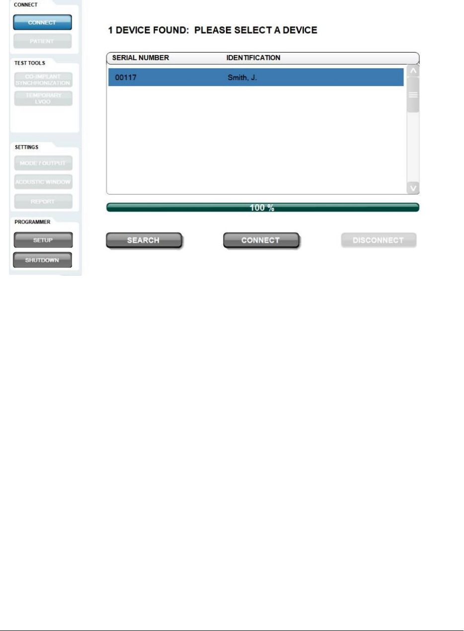
Figure 6: Connect Pulse Generator Screen
Accessible by pressing the [CONNECT] button from the main menu (Figure 4)
Select the [SEARCH] button to initiate a radio module scan for WiSE CRT Pulse Generators (Figure 6). The scan may
take up to 60 seconds and the progress bar will fill as the radio module scans for devices. The radio module’s
indicator light will blink green while scanning for devices and turn on green if a device is identified. All devices that
are found by the scan are listed by Serial Number and by Patient Name, if the Patient Name has been programmed
into the Pulse Generator.
Select the appropriate device from the list. Select the [CONNECT] button on the bottom of the window to
establish a session; select the [DISCONNECT] button to stop a session and select a different Pulse Generator from
the list.
If the radio connection between the Programmer and the Pulse Generator stops communication the No
Communication with the Pulse Generator dialog box will be displayed. To start a new programming session with
the same Pulse Generator select the [RECONNECT] button in the dialog box. Select the [SEARCH] button in the
dialog box to return to the Connection Screen.
WiSE CRT System Programmer Model 5100 Instructions for Use 9
2.2.1 Programmer Status Bar
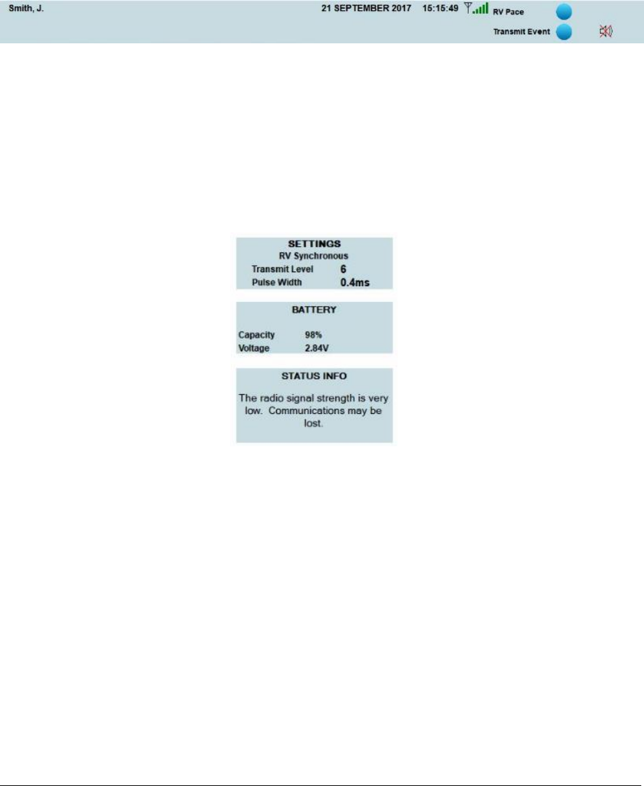
The Programmer Status Bar is continuously displayed at the top of the screen and contains a radio signal strength
indicator for the link between the radio module and the Pulse Generator and a section that updates Marker Events
in real-time as an indicator of Pulse Generator operations.
Figure 7: Programmer Status Bar
Located at the top of the display screen
2.2.2 Pulse Generator Status Bar
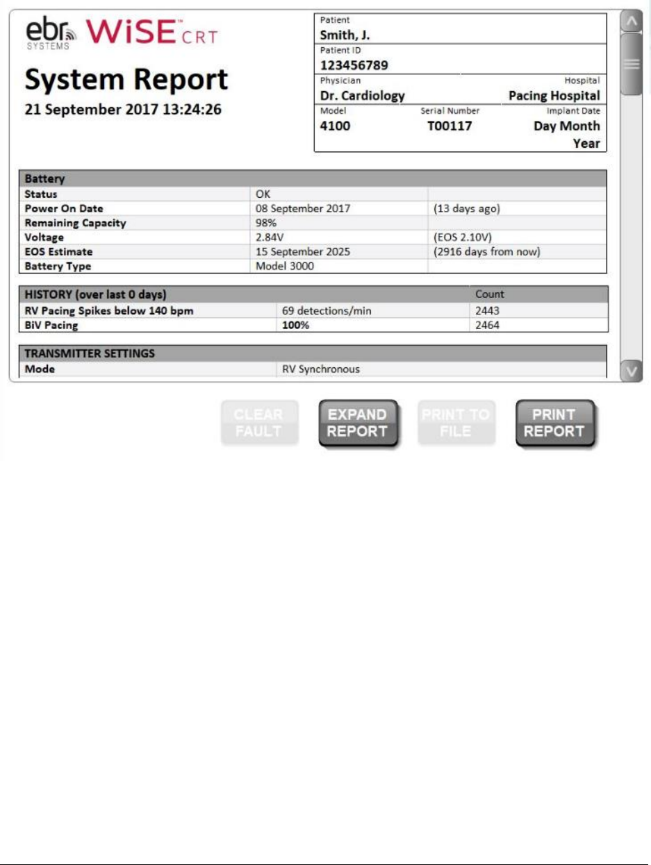
The Pulse Generator Status Bar is continuously displayed on the right hand side of the screen so that the latest
settings and interactions with the Pulse Generator may be viewed at any time (Figure 8). The Status Bar contains a
section to report the estimated remaining battery life, and a section to report any status conditions such as device
resets or end of service life flags.
Figure 8: Pulse Generator Status Bar
Located at the top of the display screen
10 WiSE CRT System Programmer Model 5100 Instructions for Use
2.3 REVIEWING AND PRINTING DEVICE DATA
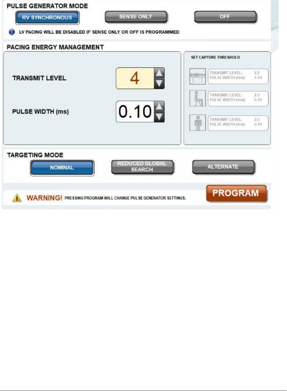
Figure 9: Report Data Screen
Accessible by pressing the [REPORT] button from the main menu (Figure 4)
After connecting to a Pulse Generator, the Programmer will interrogate the device for its settings and data and
display the Report Data screen (Figure 9). Select [EXPAND REPORT] to view and print an expanded set of collected
counter and statistic data. To review the complete settings and data, use the scroll bar to adjust the window view.
To print the settings and data select the [PRINT REPORT] button. Printed reports can be sent directly to the USB
memory modules connected to USB port on the radio module.
Select [CLEAR FAULT] to reset errors that may have been reported.
The collected data in the device may be cleared after selecting [EXPAND REPORT]. Select the [RESET HISTORY]
button to clear/reset the counter and statistic data. The following data will be cleared:
• Total number of LV Pace Attempts
• Total number of RV Pacing Spike Detections
• Query statistics including targeting transmission data
• RV pacing spike detection data
• Electrode location and distance statistics
WiSE CRT System Programmer Model 5100 Instructions for Use 11
2.4 PROGRAMMING PERMANENT PULSE GENERATOR PARAMETERS
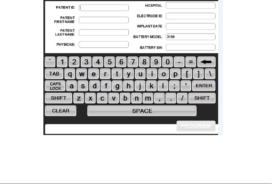
Figure 10: Mode/Output Screen
Accessible by pressing the [MODE/OUTPUT] button from the main menu (Figure 4)
The Pulse Generator may be programmed to one of three operational modes (Figure 10):
• RV Synchronous – This is the pacing mode for the Pulse Generator. In this mode, the Pulse Generator
senses RV pacing electrical outputs from the co-implanted pacemaker or defibrillator and immediately
triggers an ultrasonic transmission to the Electrode to pace the LV for bi-ventricular pacing.
• Sense Only – This is a sensing mode that disables LV pacing but allows the device to track, count, and
transmit RV Pacing Spike Detection marker events.
• Off – This mode disables pacing and sensing in the device. This is the factory default setting of the
device.
In RV Synchronous mode the Pulse Generator may be programmed to fixed settings for the transmit level and
pulse width. The pulse width is analogous to the pacing pulse width in a conventional pacing pulse. The setting of
this pulse width determines the delivered pulse width for the LV pace pulse. The transmit level does not correlate
to a specific electrical pacing voltage amplitude. The transmit level is related to the intensity of the ultrasonic
output field and is indirectly correlated to the delivered pace pulse amplitude.
The Pulse Generator may be programmed to one of three targeting modes. Targeting is essential for efficient
transfer of energy from the Pulse Generator to the Electrode. Targeting sends a series of short ultrasonic pulses
toward the last known region or location of the Electrode and senses the Electrode’s electrical output response. A
sufficient electrical response indicates that the Pulse Generator is focused on the Electrode.
12 WiSE CRT System Programmer Model 5100 Instructions for Use
• Nominal – This is the default targeting mode in the Pulse Generator. This mode uses the recent history
of electrical responses to the targeting pulses to gauge the systems effectiveness on targeting the
Electrode.
• Reduced Global Search – This targeting mode is used in circumstances where the system would
otherwise use a significant number of targeting pulses to unsuccessfully locate the Electrode. This
mode is used to conserve energy usage in the system.
• Alternate – The Alternate targeting mode is used in circumstances where the electrical output is
somewhat variable. This algorithm does not rely on prior history related to the amplitude output
signals.
To program the Pulse Generator parameters:
1. Select the [RV SYNCHRONOUS], [SENSE_ONLY], or [OFF] button.
2. If [RV SYNCHRONOUS] is selected then select the Transmit Level and the Pulse Width settings for the
device.
3. If [RV SYNCHRONOUS] is selected then select the [NOMINAL], [REDUCED GLOBAL SEARCH], or
[ALTERNATE] button.
4. Select the [PROGRAM] button.
There are 3 set capture threshold buttons to the right of the Transmit Level and Pulse Width selections. These are
used to record values onto the report that have been determined to be the capture threshold for the Transmit
Level and Pulse Width as tested in various postures, i.e. supine, sitting, and/or standing. Select the icon or the
value display area to set these values to those that are the currently active in the Transmitter. These values are
not stored in the Transmitter but do appear on the print report as an indication that a capture threshold was
determined during the follow-up session.
2.5 PATIENT INFORMATION AND DEVICE TRACKING
Figure 11: Enter Patient Information Screen
Accessible by pressing the [PATIENT] button from the main menu (Figure 4)
The tracking of patients and devices is an important safety and regulatory requirement. Information must be
entered into the Pulse Generator using the Programmer (Figure 11), and an Implanted Device Tracking Registration
Form must be completed and returned to EBR Systems, Inc.
WiSE CRT System Programmer Model 5100 Instructions for Use 13
To enter a Patient Information data field, select the data field to highlight it and then use the on-screen keyboard
to enter alphanumeric information. Obtain the serial number from the packaging, registration cards, or patient
records and check for its correct entry. Check other data entry information against patient records. Selecting the
Battery Model data field will display the Select Battery Model dialog box.
Select [PROGRAM] to communicate and confirm the changes to the Pulse Generator.
An Implanted Device Tracking Registration Form and a Patient Device Identification Card are included in each
device package and should be completed promptly at the time of the implant procedure. The tracking form is
generic and allows for 1-4 devices to be registered on a single form. One copy of the Registration Form should be
kept with the procedure/patient record and one copy must be returned to EBR Systems. The Patient Device
Identification Card is provided to the patient. Self-adhesive serial number labels are included in each package and
can be conveniently applied to the Registration Form and to patient records as may be required.
Implanted Device Tracking Registration Forms should be returned or faxed to EBR Systems, Inc. Please refer to the
cover page of this document for EBR Systems’ address and fax number.
2.6 TEST AND EVALUATION TOOLS
2.6.1 Initializing Synchronization with the Co-Implant
The WiSE CRT System relies on detecting RV pacing electrical outputs (spikes) from the co-implanted pacemaker or
defibrillator. The WiSE CRT Pulse Generator must be initialized with specific right ventricular pacing pulse width
from the co-implanted device to reliably discriminate right ventricular pacing from atrial pacing. This must be done
at implant and may be re-initialized during follow-up.
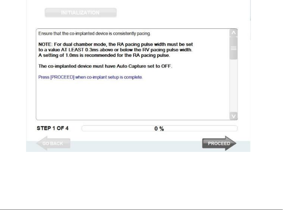
Figure 12: Co-implant Synchronization Screen
Accessible by pressing the [CO-IMPLANT SYNCHRONIZATION] button from the main menu (Figure 4)
The process requires the operator to interact with both the co-implant device and with the Pulse Generator. More
specifically, the co-implant device must be programmed to specific values for the RV pacing pulse width and the
atrial pacing pulse width.

14 WiSE CRT System Programmer Model 5100 Instructions for Use
Select the [INITIALIZATION] button after the process has started to start over.
On-screen directions are provided in the text area to set up the co-implant parameters and verify the initialization
(Figure 12):
1. Set the co-implant to provide RV pacing.
2. Set the co-implant ventricular and atrial pacing pulse widths within the required bounds. The WiSE CRT
Transmitter must be initialized with the pacing pulse widths being used by the co-implanted device.
The right ventricular pacing pulse width of the co-implant pacemaker must be programmed at or above
0.35 ms. In dual chamber modes, where atrial pacing may be expected, the right atrial pacing pulse
width of the co-implant pacemaker must be programmed at least 0.3 ms above or below the right
ventricular pulse width. A setting for right atrial pulse width above 1.0ms is most effective for the
Pulse Generator to distinguish atrial pulses from ventricular pulses.
3. Select the [PROCEED] button to confirm that the co-implant is providing RV pacing. The Enter Co-
Implant Pacing Pulse Widths dialog box (Figure 13) will appear for the operator to specify the RV pacing
pulse widths being used. Select the scroll-up and scroll-down buttons to enter the RV pacing pulse
width. RV pulse width value selections may not exactly match the resolution value of the co-implant.
In this case select the value that is the closest to the actual programmed value in the co-implant. Select
[ACCEPT] to use the pulse width value and begin the initialization. Select [CANCEL] to start the process
from the beginning.
Figure 13: Enter Co-Implant Pacing Pulse Widths dialog box
4. Use the Marker Events to confirm that the Pulse Generator is sensing RV pacing electrical outputs. The
RV Pace Detect icon should be flashing in the Marker Event section of the Pulse Generator Status Bar
and analog output marker events should be visible on the recording system. Confirm that the marker
events are synchronized to RV pacing with the ECG on the recording system.
5. The progress bar will reach 100% when synchronizing with the co-implanted device completes. If the
Pulse Generator is unable to synchronize with the co-implant, the user will be shown a message “RV
Pacing Spike Initialization unsuccessful” and can press the [PROCEED] button to start over. Once co-
implant synchronization has succeeded the user can select the [PROCEED] button to confirm to the
Pulse Generator that it is tracking RV pacing electrical outputs. Select the [GO BACK] button to start
the process over.
WiSE CRT System Programmer Model 5100 Instructions for Use 15
2.6.2 Set-Up the Alignment of the Transmitter Model 4000 with the Acoustic Window
To pace the LV with the Electrode an ultrasonic pulse from the Transmitter is emitted and targeted to the location
of the Electrode. For this to be done efficiently, the Transmitter Model 4000 must be implanted above an acoustic
window (a lung-free, bone-free path) to the Electrode. The Transmitter is composed of transducers arranged as an
array with active dimensions of 2.4 cm by 3.2 cm on one side of the enclosure. The acceptability and optimization
of alignment of the Transmitter’s transducer array can be done at implant and at follow-up.
PRECAUTION – Pacing in the LV may be inhibited while set up of the acoustic window is operating.
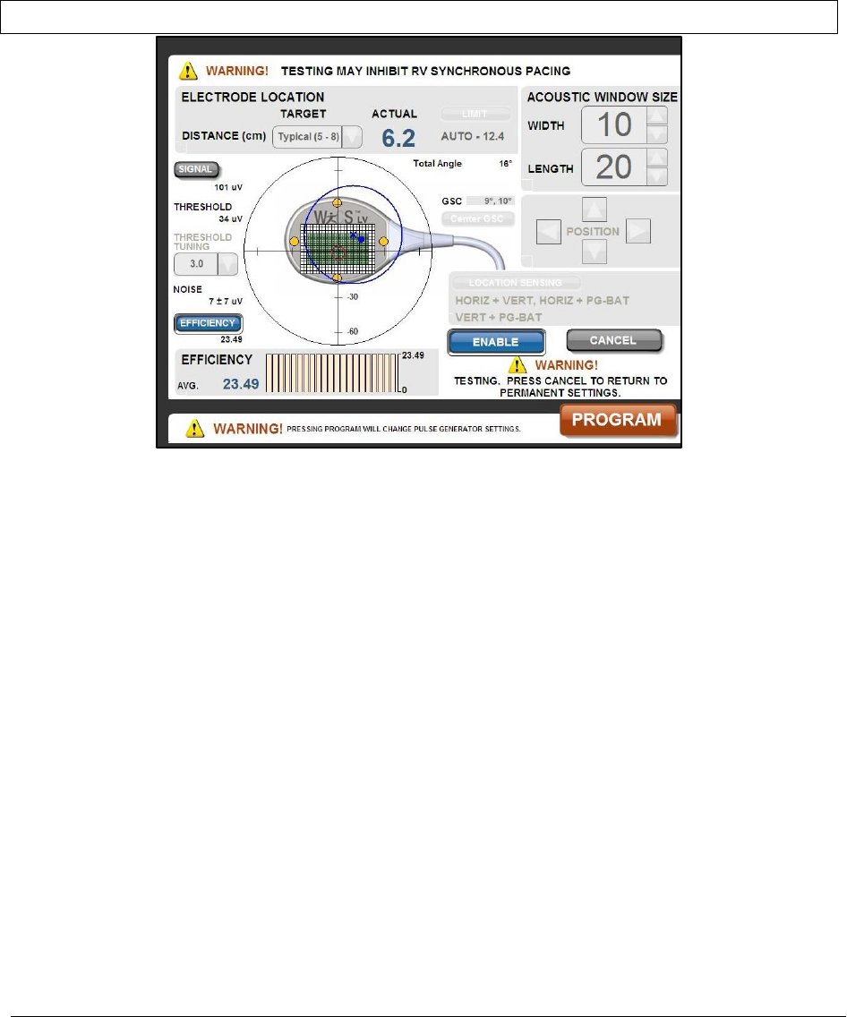
Figure 14: Transmitter Model 4000 Setup Acoustic Window Screen
Accessible by pressing the [ACOUSTIC WINDOW] button from the main menu (Figure 4)
The setup of the acoustic window evaluates the position of the Transmitter array relative to the Electrode position.
The on-screen display shows a graphic of the measured sensing and efficiency values in real time as the
Transmitter locates the Electrode (Figure 14). This is useful for monitoring the effect of the current selection being
tested. The following characteristics are visible in the graphic display:
• The array elements and position currently programmed in the Transmitter are illustrated in green.
• The array elements and position that are currently being tested are outlined with a tan border. The
number of elements and position to be tested is adjustable.
• Information related to the general location and distance to the Electrode, relative to the face of the
Transmitter, is continuously displayed as a blue dot on the graphic and as an ACTUAL distance value
above the graphic.
• The graphic depicts a circular representation of the full 180-degree hemisphere beneath the Pulse
Generator, with tick marks along the x- and y-axes indicating +/- 30 and 60 degrees. The targeting zone
for locating the Electrode is shown by a blue circle, the center of which is shown by a blue “x”. This “x”
and the corresponding target zone may be positioned anywhere within the 180-degree hemisphere.
The blue dot is expected to be within the target zone and generally near its center.
• A data area below the graphic display indicates either sensed signal levels or efficiency measurements
related to the alignment of the Transmitter with the Electrode. The signal data are the electrical
amplitudes output by the Electrode and sensed by the Transmitter in response to a targeting pulse.
They are used to determine whether the Transmitter is sufficiently focused on the Electrode. The
Efficiency is a relative measure of improvements in energy transfer when compared to other tested

16 WiSE CRT System Programmer Model 5100 Instructions for Use
values. Both the signal and efficiency data are displayed as a moving histogram. Select [EFFICIENCY]
button or select [SIGNAL] button to the left of the graphic to alternate the data display.
• One or more location sensing channels being used by the system to locate the Electrode are highlighted
by yellow dots in the graphic display. These are in the general location for the sense electrodes
arranged on the image of the Transmitter. If the system is using the battery - battery location sensing
channel this will be shown as two yellow dots on the cable graphic. The sensing channel configuration
being used is also displayed to the right of the graphic and as described below can be selected and
programmed. Select the [LOCATION SENSING] button to open a dialog box for selecting sensing
channel configurations.
• Data values related to the sensing signals used by the system to locate the Electrode are displayed to
the left of the graphic. EFFICIENCY indicates a relative measure of the energy transfer efficiency.
SIGNAL indicates the relative strength of the sensing signal used to locate the Electrode. NOISE is the
background electrical signal noise present in the sensing signal. THRESHOLD is a function of the noise
and a statistical history of the noise. The system uses the sensed signals above the threshold to
determine whether the ultrasound pulse is targeted on the Electrode. The higher the signal is above
the noise, the more statistically likely it is that the targeting is accurate. The function can be modified
by selecting a THRESHOLD TUNING setting in the pull-down menu.
At implant or at discharge, set up of acoustic window alignment with the Transmitter’s transducer array should
always be completed. At follow-up, set up of acoustic window alignment with the Transmitter’s transducer array
may be used to optimize the service life of the battery. To use the Programmer for this assessment:
1. Adjust the Acoustic Window Size, i.e. the number of the array elements, to test by selecting the
up/down buttons for the Width and Length of active elements to be used. As this is adjusted the
graphic display will outline the elements to be tested with a white/tan border.
2. Adjust the position of the array section being tested by selecting the Position arrow buttons. The
position of the array will adjust Up, Down, Left, Right within the graphic display.
3. Position the “x” representing the center of the target zone at the expected Electrode location, by
touching the desired center of the target zone with a finger or stylus. If the Electrode has been
previously found and tracked, a red ellipse will be displayed indicating the average location of the
electrode. The “x” may be placed within that ellipse manually by tapping at the new location, or by
pressing [CENTER GSC] which will automatically adjust it to the center of the ellipse.
4. Select a TARGET range from the Transmitter to the Electrode’s location by selecting a DISTANCE using
the pull-down menu. The DISTANCE is used by the system to focus the Pulse Generator’s ultrasound
output. The measured range is displayed as the ACTUAL in this screen area. The selections for the
DISTANCE are in centimeters of separation between the Electrode and the Transmitter face and include
[Close (< 4)], [Near (4 – 5)], [Typical (5 – 8)], and [Far (> 8)]. The DISTANCE is normally selected based on
the ACTUAL distance reported. If the Electrode is at a large angle, performance may be improved by
selecting a DISTANCE that is greater than the ACTUAL distance displayed. The DISTANCE pull-down
menu also contains a setting labeled OFF. Selecting OFF may be preferable for especially large
Transmitter-to-Electrode angles (total angle > 45˚). The TOTAL ANGLE is displayed to the upper right of
the graphic display area.
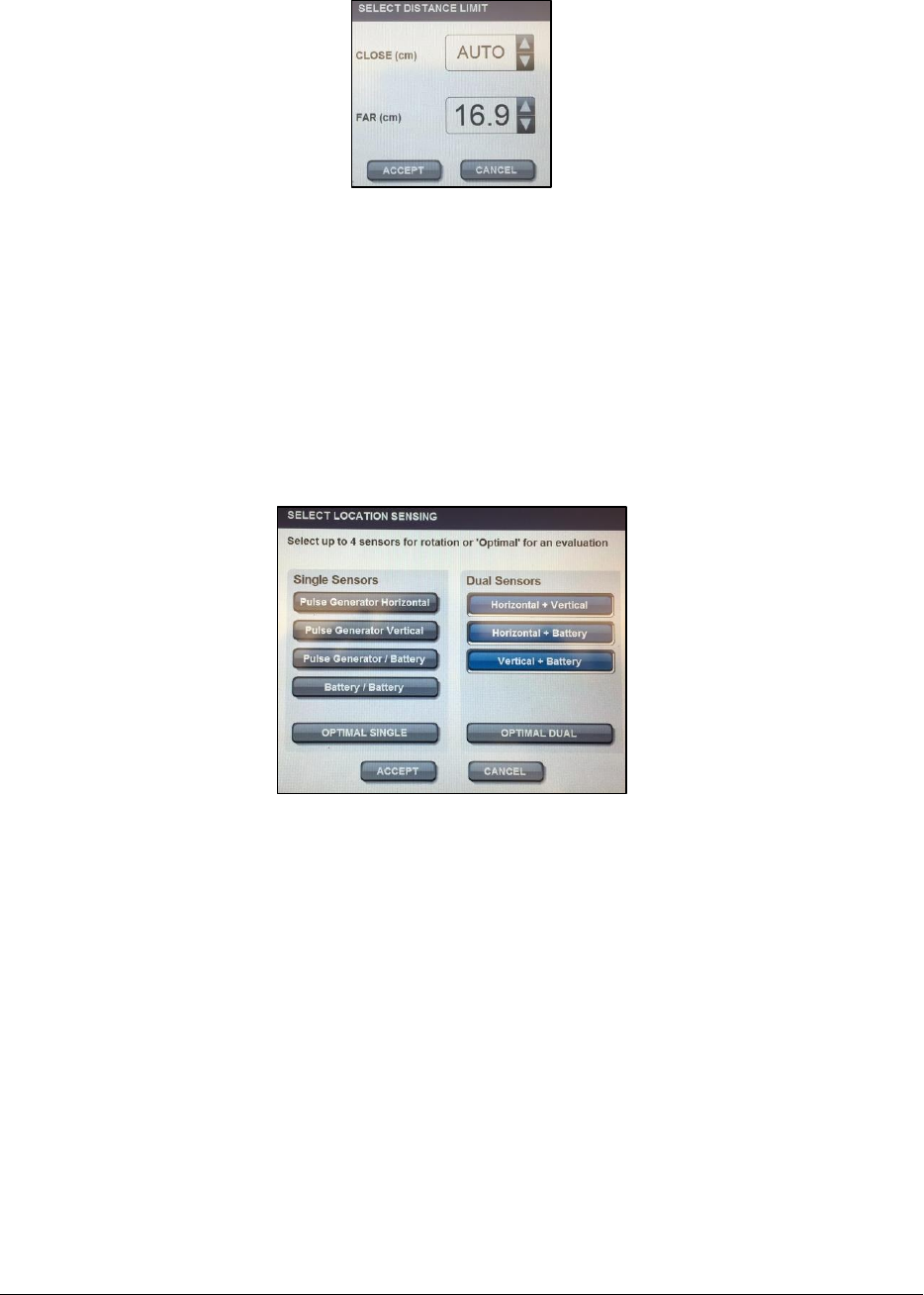
5. Select the sensing distance [LIMIT] button to open the Select Distance Limit dialog box (Figure 15) to
select the sensing range. When the CLOSE distance is set to AUTO, the system automatically calculates
the minimum sense blanking distance. In many cases, targeting can be improved by manually selecting
a CLOSE sensing distance. Typically choose a CLOSE distance that is at least 2cm less than the expected
minimum Electrode distance. The FAR distance is typically set to at least 2cm farther than the expected
maximum Electrode distance, up to a maximum of 16.9cm. Select [ACCEPT] or [CANCEL] to close the
dialog box.
WiSE CRT System Programmer Model 5100 Instructions for Use 17
Figure 15: Select Distance Limit dialog box
6. Select the system’s sensing configuration by selecting a LOCATION SENSING CHANNEL from the Select
Location Sensing dialog box (Figure 16). The configuration may be selected from a single sensor or from
dual sensor pairs. These pairs represent combinations of sensing electrodes on the exterior of the
Transmitter and Battery. Up to four selections can be made and can be mixed between single and dual
sensors. The system will dynamically rotate the use of these sensors. The rotation occurs during
operation at times when the system determines that sensing is inconsistently targeting the Electrode.
Select one to four buttons between the Single and Dual columns. Alternatively, the [OPTIMAL SINGLE]
or [OPTIMAL DUAL] selections are an automated feature which the system uses to self-select a sensing
configuration. Select [ACCEPT] or [CANCEL] to close the dialog box.
Figure 16: Select Location Sensing dialog box
7. Select the [ENABLE] button to initiate the test process.
8. Monitor the graphic and the data display areas to assess the test performance. A beat-by- beat update
of the Signal or Efficiency data will be displayed in the bar graph area scaled between 0 and the
maximum value measured. The average of all values will be displayed as a number. Also, beat by beat,
the data values related to the sensing signals will be updated. The LOCATION SENSING CHANNEL with
the best efficiency should be used to improve system performance. Monitor the Marker Events during
the testing. The display will show the counts of RV Pace Detect events and Transmit Events next to the
flashing icons.
9. During the test the [PROGRAM] button will be enabled. Select [PROGRAM] to permanently set the
Pulse Generator to the array size, position, distance limits, and sensing configuration being tested. You
can only program the settings while the test is in operation.
10. The test process will continue until cancelled, until the communication with the Pulse Generator is
interrupted, or until a Main Menu button is selected to change to another screen. Select the [CANCEL]
button to end the test. The Pulse Generator will return to its programmed mode of operation.
18 WiSE CRT System Programmer Model 5100 Instructions for Use
2.6.3 Set-Up the Alignment of the Transmitter Model 4100 with the Acoustic Window
To pace the LV with the Electrode an ultrasonic pulse from the Transmitter is emitted and targeted to the location
of the Electrode. For this to be done efficiently, the Transmitter must be implanted above an acoustic window (a
lung-free, bone-free path) to the Electrode. The Transmitter Model 4100 is composed of transducers arranged as
an array with active dimensions of 0.8 cm by 2.4 cm on one side of the enclosure. The testing and optimization of
alignment of the Transmitter’s transducer array can be done at implant and at follow-up.
PRECAUTION – Pacing in the LV may be inhibited while set up of the acoustic window is operating.
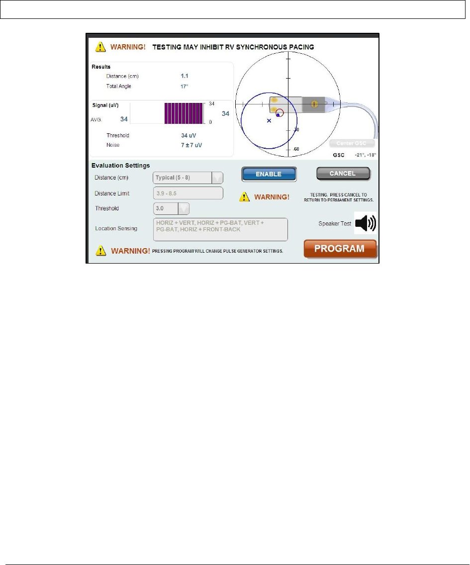
Figure 17: Transmitter Model 4100 Setup Acoustic Window Screen
Accessible by pressing the [ACOUSTIC WINDOW] button from the main menu (Figure 4)
The set-up of the acoustic window evaluates the position of the Transmitter array relative to the Electrode
position. The array elements that are currently being tested are not adjustable. The entire array area of 0.8 cm by
2.4 cm is active during the testing. The on-screen display shows the location and sensing signal values as
measured in real time as the Transmitter locates the Electrode (Figure 17). This is useful for monitoring the effect
of the current selections being tested. The following characteristics are visible in the graphic display:
• Information related to the general location and distance to the Electrode, relative to the face of the
Transmitter, is continuously displayed as a blue dot on the graphic and as actual distance and angle
values in the Results next to the graphic.
• The graphic depicts a circular representation of the full 180-degree hemisphere beneath the Pulse
Generator, with tick marks along the x- and y-axes indicating +/- 30 and 60 degrees. The targeting zone
for locating the Electrode is shown by a blue circle, the center of which is shown by a blue “x”. This “x”
and the corresponding target zone may be positioned anywhere within the 180-degree hemisphere.
The blue dot is expected to be within the target zone and generally near its center.
• One or more location sensing channels being used by the system to locate the Electrode are highlighted
by yellow dots in the graphic display. These are in the general location for the sense electrodes
arranged on the image of the Transmitter. The location sensing channel configuration being used is
also displayed below the graphic and as described below can be selected and programmed.

WiSE CRT System Programmer Model 5100 Instructions for Use 19
• Data areas to the left of the graphic display indicates sensed signal levels related to the alignment of
the Transmitter with the Electrode. The Signal (μV) data are the electrical amplitudes output by the
Electrode as sensed by the Transmitter in response to a targeting pulse and are used to indicate the
relative strength of the sensing signal used to locate the Electrode. Noise is the background electrical
signal noise present in the sensing signal. Threshold is a function of the noise and a statistical history of
the noise. They are used to determine whether the Transmitter is sufficiently focused on the
Electrode. The signal data itself is displayed as an absolute value and as a moving average. The system
uses the sensed signals above the threshold to determine whether the ultrasound pulse is targeted on
the Electrode. The higher the signal is above the noise, the more statistically likely it is that the
targeting is accurate. The function can be modified by selecting a Threshold setting in the pull-down
menu.
At implant or at discharge, set up of acoustic window alignment with the Transmitter’s transducer array should
always be completed.
To use the Programmer for this assessment:
1. Position the “x” representing the center of the target zone at the expected Electrode location, by
touching the desired center of the target zone with a finger or stylus. If the Electrode has been
previously found and tracked, a red ellipse will be displayed indicating the average location of the
electrode. The “x” may be placed within that ellipse manually by tapping at the new location, or by
pressing [CENTER GSC] which will automatically adjust it to the center of the ellipse.
2. Select a targeting range from the Transmitter to the Electrode’s location by selecting a Distance (cm)
using the pull-down menu. The Distance is used by the system to focus the Pulse Generator’s
ultrasound output. The measured range is displayed as an actual value in the Results screen area. The
selections for the Distance is in centimeters of separation between the Electrode and the Transmitter
face and include [Close (< 4)], [Near (4 – 5)], [Typical (5 – 8)], and [Far (> 8)]. The Distance is normally
selected based on the measure value reported. If the Electrode is at a large angle, performance may be
improved by selecting a Distance that is greater than the measured distance displayed. The Distance
pull-down menu also contains a setting labeled “Off”. Selecting “Off” may be preferable for especially
large Transmitter-to-Electrode angles (total angle > 45˚). The Total Angle is displayed to the Distance
measured value.
3. Select the Distance Limit display area to open the Select Distance Limit dialog box (Figure 18) to select
the sensing range. When the CLOSE distance is set to AUTO, the system automatically calculates the
minimum sense blanking distance. In many cases, targeting can be improved by manually selecting a
CLOSE sensing distance. Typically choose a CLOSE distance that is at least 2cm less than the expected
minimum Electrode distance. The FAR distance is typically set to at least 2cm farther than the expected
maximum Electrode distance, up to a maximum of 16.9cm. Select [ACCEPT] or [CANCEL] to close the
dialog box.
Figure 18: Select Distance Limit dialog box
20 WiSE CRT System Programmer Model 5100 Instructions for Use
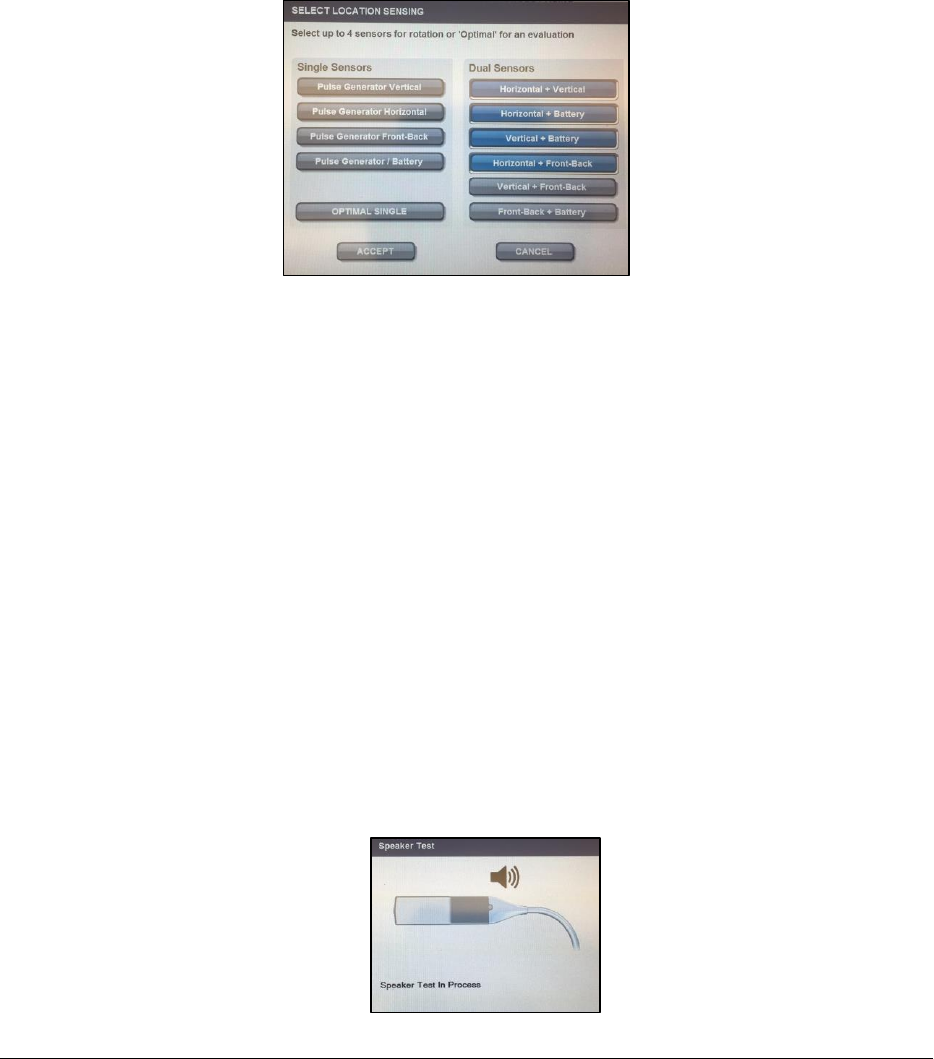
4. Select the Location Sensing configuration display area to open the Select Location Sensing dialog box
(Figure 19). The configuration may be selected from a single sensor or from dual sensor pairs. These
pairs represent combinations of sensing electrodes on the exterior of the Transmitter and Battery. Up
to four selections can be made and can be mixed between single and dual sensors. The system will
dynamically rotate the use of these sensors. The rotation occurs during operation at times when the
system determines that sensing is inconsistently targeting the Electrode. Select one to four buttons
between the Single and Dual columns. Alternatively, the [OPTIMAL SINGLE] selection is an automated
feature which the system uses to self-select a sensing configuration. Select [ACCEPT] or [CANCEL] to
close the dialog box.
Figure 19: Select Location Sensing dialog box
5. Select the [ENABLE] button to initiate the test process.
6. Monitor the data display areas to assess the test performance. A beat-by- beat update of the Signal
level value will be displayed. The average of all values will be displayed as a number. Monitor the
Marker Events during the testing. The display will show the counts of RV Pace Detect events and
Transmit Events next to the flashing icons.
7. During the test the [PROGRAM] button will be enabled. Select [PROGRAM] to permanently set the
Pulse Generator to the distance limits and sensing configuration being tested. You can only program
the settings while the test is in operation.
8. The test process will continue until cancelled, until the communication with the Pulse Generator is
interrupted, or until a Main Menu button is selected to change to another screen. Select the [CANCEL]
button to end the test. The Pulse Generator will return to its programmed mode of operation.
2.6.4 Transmitter Model 4100 Speaker Test for Battery
An audible notification exists in the Transmitter Model 4100 to indicate the progression of the depletion of the
implanted battery. The audible notification may be tested from the Setup Acoustic Window screen (Figure 17) to
determine whether the notification can be perceived by the patient:
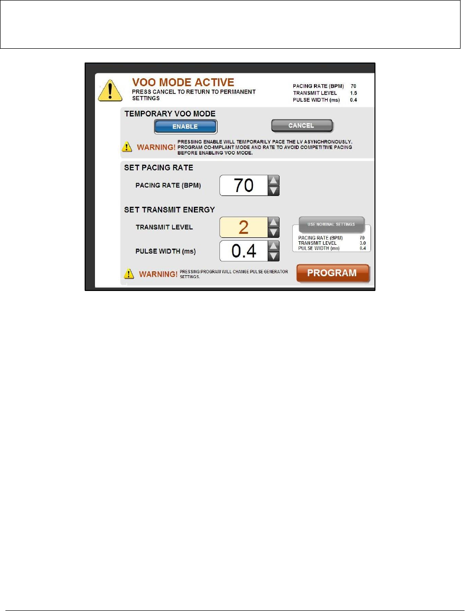
1. Select the Speaker Test button. The Speaker Test dialog box (Figure 20) will be displayed for 8 seconds
while the speaker in the Transmitter emits the audible notification sequence (five half-second audible
tones, separated by one second silence between tones).
Figure 20: Transmitter Model 4100 Speaker Test dialog box
WiSE CRT System Programmer Model 5100 Instructions for Use 21
2.6.5 Initiating Temporary LVOO Mode
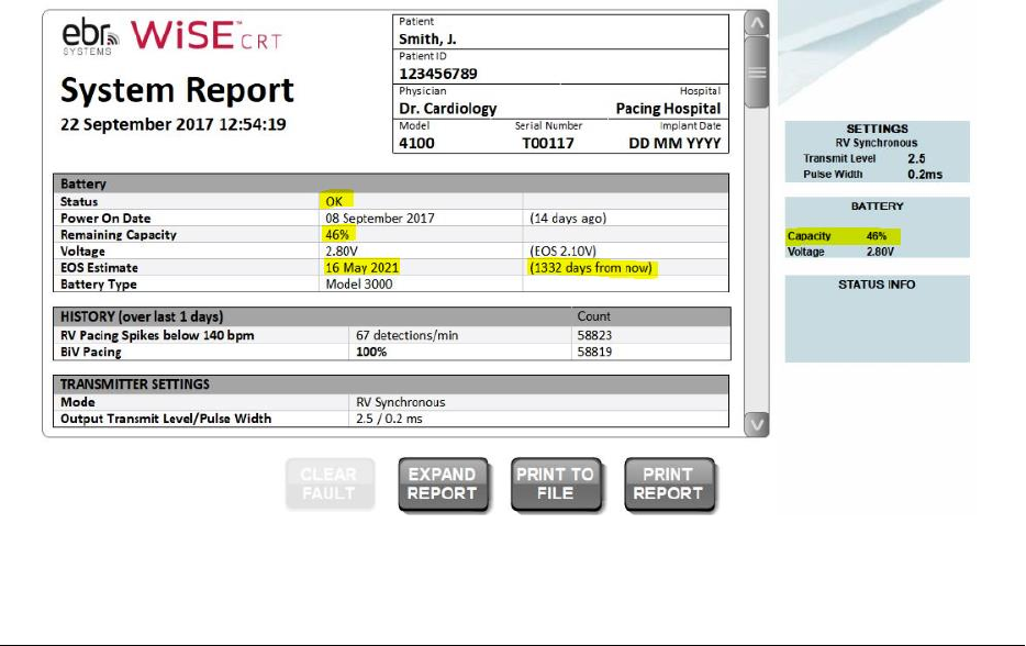
The Pulse Generator may be programmed to temporarily deliver asynchronous pacing to the LV (Figure 21).
PRECAUTION – In Temporary LVOO mode the Pulse Generator delivers pacing without synchronizing its output
with the co-implanted device. Ensure that the co-implanted rate is lower than the LV rate to avoid
competitively pacing the ventricles. Ensure that any co-implant anti-tachy therapies are disabled or
reprogrammed such that Temporary LVOO pacing is not sensed by the co-implant’s detection algorithms.
Figure 21: Temporary LVOO Mode Screen
Accessible by pressing the [TEMPORARY LVOO MODE] button from the main menu ((Figure 4)
To program the Pulse Generator to temporary LVOO mode:
1. Select the Pacing Rate, Transmit Level and Pulse Width.
2. Select the [ENABLE] button.
Select [CANCEL] button to terminate the temporary pacing and return to the programmed mode. If at any time
the communication link between the Programmer and Pulse Generator is lost, the temporary LVOO mode will be
automatically cancelled by the Pulse Generator.

22 WiSE CRT System Programmer Model 5100 Instructions for Use
3 SYSTEM EVALUATION DURING IMPLANT AND FOLLOW-UP
3.1 INITIALIZING THE SYSTEM
The Battery and Transmitter must be within their pockets, and the pockets flushed with sterile saline to remove
air, in order to initialize the system. The Electrode and the Pulse Generator are not active until the Pulse
Generator has been initialized using the Programmer. Once the Electrode has been implanted, initializing the
Transmitter is important for optimal performance of the system.
To complete the initialization of the System:
1. Establish a Programming session (a communication link) with the Pulse Generator.
2. Program patient information into the Pulse Generator.
3. Ensure that the co-implant is set to a mode to promote RV stimulation, and that the RV pacing pulse
width is set to the value entered during co-implant synchronization.
4. Set up sensing for Co-Implant Synchronization.
5. Set up the acoustic window so that it is optimized for the alignment of the transmitter.
6. Assess the EKG for bi-ventricular pacing. Observe changes in the EKG to confirm that the system is
tracking the co-implant and LV pacing is being achieved with the system.
3.2 BATTERY MODEL SELECTION
For the Pulse Generator to estimate the service life of the Battery module it must know which Battery Model has
been connected. This is done at the time of Battery implant. At the first connection of the Programmer to the
Pulse Generator after Battery connection, the Programmer will display a Select Battery Model dialog box. Select
the Battery Model that is connected to the Pulse Generator and then select the [PROGRAM] button.
WiSE CRT System Programmer Model 5100 Instructions for Use 23
3.3 BATTERY STATUS AND END OF SERVICE
The energy usage is monitored by the Pulse Generator to estimate and report on the service life of the Battery
module. Energy usage is based on the individual settings and specific power usage of the device. The Programmer
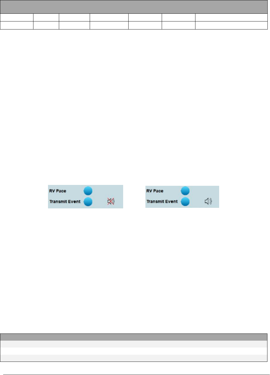
provides an end of service (EOS) date on the Programmer screen and on the printout as highlighted in Figure 22.
Regular device checks are a critical component of care and the EOS date must be reviewed at each device check. At
EOS, the transmitter will no longer provide ultrasound transmissions. Replace the Battery module immediately if
the Programmer indicates EOS has been reached.
The EOS date is used for determining the Recommended Replacement Time (RRT). The RRT is 3 months before the
EOS date reported on the screen and printout. If the EOS date is 3 months or less on the day of the device check,
then the patient should be scheduled for a procedure to replace the Battery. The Battery is replaced without
removing or replacing the Transmitter. In addition to the RRT, the battery voltage is measured by the Pulse
Generator and the remaining battery capacity is estimated. These are also reported as highlighted in Figure 22.
When the battery voltage for the implanted battery reaches 2.6V, the implanted Pulse Generator will generate a
patient notification consisting of twenty (20) half-second audible tones separated by one second of silence
between tones. This patient alert notification repeats every eight (8) hours, until either the battery is replaced or
the system is programed with settings that extend battery longevity (e.g. lower transmit levels and wider pulse
widths could be used to increase battery life). The audible notification may be tested from the Setup Acoustic
Window screen (Figure 17) to determine whether the audible notification can be perceived by the patient (see
section 2.6.4)
IMPORTANT! Audible patient notification for Battery voltage level is only available with the Transmitter Model
4100.
The Pulse Generator Status bar and the Report Data area will contain indications of the battery status. The
measured battery voltage is reported, an estimate of the remaining battery capacity is provided, and an estimated
date of end of service is reported.
Figure 22: Report Screen with illustrative highlights included showing Battery status
Screen is accessible by pressing the [REPORT] button from the main menu (Figure 4)

24 WiSE CRT System Programmer Model 5100 Instructions for Use
3.4 BATTERY LONGEVITY
WARNING – Early Battery Depletion: Higher than expected energy requirements for transmitting ultrasound to
activate the Electrode may result in early depletion of the Battery. Patient follow-up every 3 months is required
to assess Battery capacity and projected longevity (i.e. service life). Discuss with each patient the importance of
their regular device check as a critical component of their care. Advise the patients that if they become
symptomatic again, similar to their condition before the WiSE CRT System was implanted, they should contact
their physician at the implanting center. Advise the patient that their WiSE CRT System can only be assessed at
their implanting center. Prior to obtaining the patient’s consent for the procedure, discuss with each patient
that Battery replacements will be required. Discuss the following important topics:
1. The surgical process of Battery removal and replacement.
2. In clinical investigations, the battery was replaced at between 8 months and 3 years.
3. The patient may need a Battery replaced each year.
4. The Battery use and prediction for how long it will last can only be determined at a follow-up visit at
their implanting center.
The longevity of the Battery is affected by several important operating conditions that vary for each implanted
system. The following recommendations should be considered to improve the efficiency of the system:
RECOMMENDATIONS TO IMPROVE PROJECTED BATTERY LONGEVITY
During implant
procedures
• The distance between the Electrode and the face of Transmitter array is 10 cm or less.
• The Electrode and the face of the Transmitter array is 30° or less from array-normal.
• Implant the Transmitter securely to the inter-costal muscle over an acoustic window
(lung-free and rib-free transmission path to potential LV implant sites) that is at least 1cm
x 2.5cm.
• Implant the Electrode in excitable tissue with an acute electrical capture threshold less
than 2V at 0.5 ms pulse width.
During patient
follow-up
visits
• Optimize programmed transmit level and pulse width setting to achieve consistent left
ventricular pacing while maximizing battery longevity. When possible, lower transmit
levels and wider pulse widths should be used to increase battery life.
• Refer to the WiSE CRT report for battery end of service (EOS) estimate that is generated
by the Programmer and based on the system’s current settings. For more information on
the WiSE CRT report, see section 3.3, Battery Status and End of Service.
The projected battery longevity in years is shown in the following tables for different WiSE CRT Transmitter model
and Battery model combinations. As shown, battery longevity is affected by pacing rate and the programmed
settings, such as the transmit level and pulse width.
IMPORTANT! Projected longevity estimates are based on accelerated battery discharge data, device modeling and
typical shelf life storage time. Do not interpret these values as precise numbers.
TRANSMITTER MODEL 4000 ASSUMING 100% TRACKING AND PACING
Battery
Usage
Pacing Rate
Transmit Level
Pulse Width
Aperture
Projected Longevity (years)*
Model 3000
Nominal
70 ppm
4
0.3 ms
8x24
2.2
Model 3100
Nominal
70 ppm
4
0.3 ms
8x24
3.3
IMPORTANT! Under extreme usage scenarios (i.e., pacing rate: 90 pmm, transmit level: 6, pulse width: 1.5ms),
projected battery longevity with the Transmitter Model 4000 when using the Battery Model 3000 is 0.3 years, and
when using the Battery Model 3100 is 0.4 years.
WiSE CRT System Programmer Model 5100 Instructions for Use 25
TRANSMITTER MODEL 4100 ASSUMING 100% TRACKING AND PACING
Battery
Usage
Pacing Rate
Transmit Level
Pulse Width
Aperture
Projected Longevity (years)
Model 3000
Nominal
70 ppm
4
0.3 ms
8x24
3.0
Model 3100
Nominal
70 ppm
4
0.3 ms
8x24
4.5
IMPORTANT! Under extreme usage scenarios (i.e., pacing rate: 90 pmm, transmit level: 6, pulse width: 1.5ms),
projected battery longevity with the Transmitter Model 4100 when using the Battery Model 3000 is 0.7 years and
when using the Battery Model 3100 is 1.0 year.
3.5 USING MARKER EVENTS
The WiSE CRT Pulse Generator communicates the occurrence of real-time operational events to the Programmer
using the RF communication link. The Programmer provides two types of outputs to signal the occurrence of these
events: 1) via flashing indicator icons on the display and 2) via an analog output channel that when connected to
typical recording equipment aligns the event signal output with ECG signals.
Two real-time operational events are communicated by the Pulse Generator with flashing icons and audible tones:
1. The detection of an RV pacing electrical output spike originating from the co-implanted device, referred
to as an RV Pace Detect event.
2. The transmission of an ultrasonic pulse directed at the Electrode intended to pace the LV, referred to as
a Transmit Event.
During Acoustic Window testing counts of events are displayed next to the icons. Audible tones are enabled by
selecting or deselecting the speaker icon (Figure 23).
Figure 23: Marker event audible tones are enabled by selecting or deselecting the speaker icon
Marker events are dependent on the programmed settings and the operational mode of the Pulse Generator.
In RV Synchronous mode:
• RV Pace Detect and Transmit Event occur with a pacing spike detection that triggers an ultrasound
transmit.
• RV Pace Detect events occur with pacing spike detections that does not trigger an ultrasound transmit,
for example if the detection occurs within the High Rate Limit Interval (430 ms) or the ultrasound
transmission does not occur due to an inability to target the Electrode.
Marker Events are discernible on an analog output channel by interpretation of the polarity and the amplitude of
square wave signals (Figure 24). The signal amplitude and pulse width, as well as a calibration output, for the
signals may be established in the Programmer Set-up screen previously described (Figure 5). Inputting the analog
signal into recording and display instrumentation that is monitoring the ECG will assist with set-up of the system,
evaluation of operation, and troubleshooting. Marker Events are also discernible when the audio output is
enabled.
EVENT
MARKER PULSE
TONE
RV Pace Detect and Transmit Event
Full amplitude positive
High pitch tone
Asynchronous Transmit Event
½ amplitude positive
High pitch tone
RV Pace Detect without Transmit Event
Full amplitude negative
Low pitch tone
OR

26 WiSE CRT System Programmer Model 5100 Instructions for Use
Figure 24: Marker event calibration sequence
3.6 TROUBLESHOOTING
ISSUE DESCRIPTION
POSSIBLE CAUSE
TROUBLESHOOTING AND CORRECTIONS
No LV Pacing
RV Synchronous mode
not programmed
• Reprogram Transmitter for synchronous pacing.
Co-implant is not
pacing
• Check and reprogram co-implant device mode and
rates.
No RV pacing spike is
being detected
• Check that the co-implant is properly programmed for
WiSE CRT RV spike detection. Reinitialize Pacing Spike
Detection.
• Reinitialize Pacing Spike Detection to shorter RV pulse
widths.
• Increase RV pace amplitude to test for improved
detection.
Battery depleted, cable
fractured, not
connected, or
connector failed.
• Check system status with the Programmer. Replace
Battery module when depleted.
Failure of the Electrode
OR
Failure to target the
Electrode
• Use Temporary LVOO pacing operation to check for
Electrode output (pacing spike) at any energy setting.
• Evaluate locations of Electrode and Transmitter on
previous and new chest X-rays to check for movement
causing no targeting (no pacing spike).
• Use Acoustic Window set up to check for possible
movement of the Electrode or the Transmitter causing
poor targeting.
• Use Acoustic Window set up to improve targeting by
choosing/optimizing [LOCATION SENSING] electrodes.
• Use Acoustic Window set up to adjust the [THRESHOLD
TUNING] value to set a reasonable signal to noise
threshold.
Transmit Energy set too
low
• Adjust Transmit Energy (Transmit Level, Pulse Width) to
achieve LV pacing capture.
RV Pace
Detect Only
Transmit
Event
Only
RV Pace Detect
and Transmit
Event

WiSE CRT System Programmer Model 5100 Instructions for Use 27
ISSUE DESCRIPTION
POSSIBLE CAUSE
TROUBLESHOOTING AND CORRECTIONS
LV Pacing but not
Synchronized to RV
Pulse widths not
programmed correctly in
co-implant
• Check and reprogram co-implant for correct pulse
widths. Reinitialize Pacing Spike Detection.
Noise being sensed as RV
pacing spikes.
• Investigate noise sources. Reinitialize Pacing Spike
Detection.
Temporary LVOO mode is
active
• Check the operational mode with the Programmer.
Pacing is synchronized to
RA
• Check and reprogram co-implant for correct pulse
widths. Reinitialize Pacing Spike Detection.
• The most reliable detection operation is with RA pulse
widths >1.0ms.
No communication
session can be
established with
the Pulse Generator
Programmer Failure
• Re-boot Programmer to run self-test. Communicate
with an alternative Transmitter to check functionality.
Interference
• Arrange patient and radio module to improve the
signal strength.
Weak signal strength
• Check signal strength indicator. Arrange patient and
radio module to improve the signal strength.
Battery depleted
• Check patient records for device longevity history.
Battery cable fractured or
not connected
• X-ray devices and check for cable fracture.
Early Battery
Depletion
Reduction of the acoustic
window Area
• Use Acoustic Window set up to adjust use of
Transmitter aperture.
• If necessary, reposition Transmitter in pocket.
Acoustic window area
larger than needed,
resulting in poor
efficiency
• Use Acoustic Window set up to adjust use of
Transmitter.
Manual pacing
parameters set too high
• Reprogram.
Poor targeting
• Use Acoustic Window set up to adjust LOCATION
SENSING electrodes, DISTANCE TARGET and DISTANCE
LIMIT
No Marker Events
Communication link has
stopped
• Check signal strength indicator. Arrange patient and
radio module to improve the signal strength.
Cable not connected to
Programmer.
• Check that analog output cable is connected. Use the
[CALIBRATE MARKER OUTPUT] feature in the
Programmer Setup.
Transmitter programmed
off – no pacing or sensing
setup
• Check and reprogram Transmitter.
Communication
errors with the
Pulse Generator
Interference or weak
signal strength
• Arrange patient and radio module to improve the
signal strength.

28 WiSE CRT System Programmer Model 5100 Instructions for Use
ISSUE DESCRIPTION
POSSIBLE CAUSE
TROUBLESHOOTING AND CORRECTIONS
Initializing RV
Pacing Spike
Detection with the
Programmer fails
Co-implant not
programmed for RV
detectable pulse width
above 0.35 ms.
• Program co-implant. Restart Pacing Spike Detection.
Co-implant not pacing.
• Check and reprogram co-implant for mode and rates.
Acoustic Window
assessment
identifies small
area
Transmitter or Electrode
has moved.
• Use Acoustic Window set up to adjust use of
Transmitter aperture.
• If necessary, reposition Transmitter in pocket.
No electrogram or
pacing with the
Delivery Catheter
Connection to the
Electrode is disconnected
in the Catheter or the
Extension Cable is not
connected.
• Check connections.
• Replace cable and retry.
• Withdraw Delivery Catheter System and replace.
Not connected to
recording or pacing
instruments
• Check connections from Catheter to equipment.

WiSE CRT System Programmer Model 5100 Instructions for Use 29
4 TECHNICAL SPECIFICATIONS
4.1 PHYSICAL AND ELECTRICAL SPECIFICATIONS
PHYSICAL SPECIFICATIONS
Tablet Computer (H x W x T)
20.3 cm x 31.2 cm x 2.4 cm
Radio Module Footprint (W x L) / Height
7.4 cm x 9.4 cm / 13.0 cm
Mass (Tablet / Radio Module)
1.3 kg / 0.3 kg
Radio Module Cable Length
3.0 meters
AC/DC Power Adapter/ Cord Length
3.8 meters
Marker Events Cable Length
3.0 meters
ELECTRICAL SPECIFICATIONS
AC Line Voltage
100-240 VAC
Power Input
1.6 A @ 100 VAC
AC Frequency
50/60 Hz
RF Reception Band
402-405 MHz (Medical Implant Communication Service/MedRadio
rules)
RF Transmission Bands
Frequency: 402.15-404.85 MHz (MICS/MedRadio band)
Modulation: 2-FSK @ 200 kbps
Effective Radiated Power: -16 dBm maximum
Frequency: 2.443-2.457 GHz (ISM band)
Modulation: Manchester-encoded OOK (100%)
Effective Radiated Power: +20 dBm maximum
DC Power Supply
Use only the AC power adapter provided with the Programmer to
maintain electrical safety.
ENVIRONMENTAL SPECIFICATIONS
Operating temperature range
+15˚C to +35˚C
Storage temperature range
-10˚C to +55˚C
Operating Relative humidity (maximum)
10% to 90% (non-condensing)
Operating Altitude
<2000 meters
4.2 PARAMETER SPECIFICATIONS
SETUP PARAMETERS
Values/Range
Increments
Marker Output Level (mV)
10, 20, 50, 100, 200, 500, 1000
Marker Output Pulse Width (ms)
1.0-20.0
1.0
Display Brightness
1-10
1
Speaker Volume
0-10
1
OPERATIONAL OUTPUT PARAMETERS
Range
Tolerance
Marker Output Level (mV)
10 - 1000
±15mV or ±10%
Marker Output Pulse Width (ms)
1.0-20.0
0.1

30 WiSE CRT System Programmer Model 5100 Instructions for Use
4.3 PROGRAMABLE PULSE GENERATOR VALUES
PERMANENT PARAMETERS
Values/Range
Mode
RV Synchronous, Sense Only, OFF
Transmit Level
1, 1.5, 2, 2.5, 3, 4, 5, 6
Transmit Pulse Width (ms)
0.01, 0.02, 0.05, 0.07, 0.1, 0.15, 0.2 to 2.0 in increments of 0.1,
2.5, 3.0, 3.5, 4.4
CO-IMPLANT PARAMETERS
Values/Range
Increments
RV Pulse Width dual chamber (ms)
0.70 – 0.80
0.05
Atrial Pulse Width dual chamber (ms)
0.35 – 2.00
0.05
RV Pulse Width single chamber (ms)
0.35 – 2.00
0.05
TEMPORARY LVOO PARAMETERS
Values/Range
Increments
Pacing Rate (bpm)
30 – 150
5
Transmit Level
1, 1.5, 2, 2.5, 3, 4, 5, 6
Pulse Width (ms)
0.01, 0.02, 0.05, 0.07, 0.1, 0.15, 0.2 to
2.0 in increments of 0.1, 2.5, 3.0, 3.5,
4.4
4.4 TECHNICAL SERVICE AND SUPPORT
WARNING - No modification of the Programmer is allowed except by authorized service personnel of
EBR Systems.
EBR Systems installs the Model 5100 Programmer in the medical facility and when necessary EBR Systems installs
any new Software products that become available for the Programmer. Maintenance and service for the
Programmer can only be performed by EBR Systems. Should a Programmer require service it will be exchanged.
The Programmer should be tested biennially by an EBR Systems representative. It is the medical facility’s
responsibility to schedule biennial testing by contacting EBR Systems.
4.5 CLEANING AND DISPOSAL OF DEVICES
The Programmer may be cleaned by wiping the exposed surfaces using isopropyl alcohol. The Programmer
contains typical electronic components that require consideration for disposal. Return the Programmer to EBR
Systems or follow proper e-waste disposal procedures as recommended for personal computers.
Contact EBR Systems to be supplied with materials related to returning devices for disposal.

WiSE CRT System Programmer Model 5100 Instructions for Use 31
4.6 EMC INFORMATION
This device complies with part 15 of the FCC Rules. Operation is subject to the following two conditions: (1) This
device may not cause harmful interference, and (2) this device must accept any interference received, including
interference that may cause undesired operation.
WARNING – The Programmer should not be used adjacent to or stacked with other equipment and that if
adjacent or stacked use is necessary, the Programmer should be observed to verify normal operation in the
configuration in which it will be used.
WARNING – The Programmer may be interfered with by other equipment, even if that other equipment
complies with the CISPR emission requirements.
WARNING – Use of accessories, transducers, and cables other than those specified or provided could result in
increased electromagnetic emissions or decreased electromagnetic immunity of the Programmer and result in
improper operation.
WARNING – Portable RF communications equipment (including peripherals such as antenna cables and external
antennas) should be used not closer than 30 cm (12 inches) to any part of the Programmer, including cables
specified for use with the Programmer.
32 WiSE CRT System Programmer Model 5100 Instructions for Use
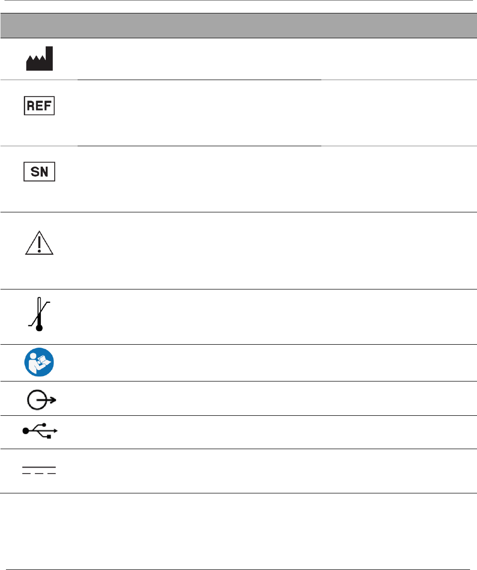
5 SYMBOL GLOSSARY
SYMBOL
STANDARD
REFERENCE
STANDARD
TITLE
SYMBOL
TITLE
EXPLANATORY
TEXT
ISO 15223-1,
Clause 5.1.1
Medical devices — Symbols to be used with
medical device labels, labelling and
information to be supplied.
Manufacturer
Indicates the medical
device manufacture.
ISO 15223-1,
Clause 5.1.6
Medical devices — Symbols to be used with
medical device labels, labelling and
information to be supplied.
Catalogue or
model
number
Indicates the
manufacturer’s
catalogue number so
that the medical
device can be
identified.
ISO 15223-1,
Clause 5.1.7
Medical devices — Symbols to be used with
medical device labels, labelling and
information to be supplied.
Serial number
Indicates the
manufacture’s serial
number so that a
specific medical
device can be
identified.
ISO 15223-1,
Clause 5.4.4
Medical devices — Symbols to be used with
medical device labels, labelling and
information to be supplied.
Attention:
Read all
warnings and
precautions
in
instructions
for use.
Indicates the need
for the user to consult
the instructions for
use for important
cautionary
information.
ISO 15223-1,
Clause 5.3.7
Medical devices — Symbols to be used with
medical device labels, labelling and
information to be supplied.
Storage
temperature
range
Indicates the
temperature limits to
which the medical
device can be safely
exposed.
IEC 60601-1,
Table D.2,
Symbol 10
Medical electrical equipment — Part 1:
General requirements for basic safety and
essential performance.
Follow
instructions
for use
Refer to instruction
manual/booklet.
IEC 60417-
5035
Graphical symbols for use on equipment.
Output
To identify an output
terminal.
Graphical symbols for USB connection
To identify USB port.
IEC 60417-
5031
Graphical symbols for use on equipment.
Direct current
To indicate on the
rating plate that the
equipment is suitable
for direct current only.
SYMBOL
STANDARD
REFERENCE
STANDARD
TITLE
SYMBOL
TITLE
EXPLANATORY
TEXT
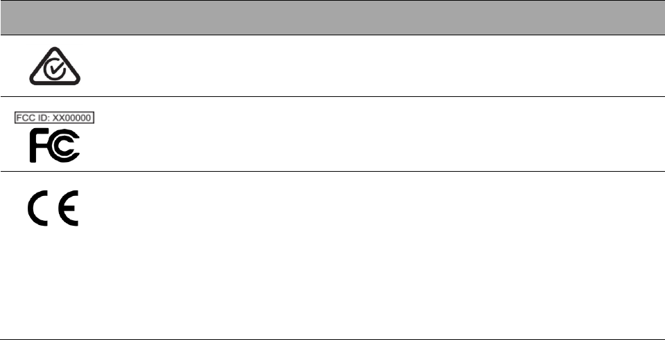
AS/NZS
4417.1:2012
Australian Radio Communications Requirements.
Complies with
Australian Radio
communications
requirements.
47 CFR Part 15
Federal Communication Commission Number (FCC
ID #)
Complies with
United States Radio
communication
requirements.
765/2008/EC
768/2008/EC
MDD
90/385/EEC
199/5/EC
The requirements for accreditation and market
surveillance relating to the marketing of products;
Medical Device Directive.
Signifies conformity
to the European
Active Implantable
Medical Device
Directive version
M4 90/385/EEC and
Radio &
Telecommunication
s Terminal
Equipment
(199/5/EC).

© 2018 EBR Systems, Inc.
All Rights Reserved.
WiSE is a trademark of EBR Systems, Inc.