ECI Satellite Communication A S ECIST4120 Irridium telephone set User Manual M4150GB0 0 p65
ECI Satellite Communication A/S Irridium telephone set M4150GB0 0 p65
UserManual.wiki
>
ECI Satellite Communication A S
>
ECIST4120 User Manual
>
INSTALLATION MANUAL
Contents
1.
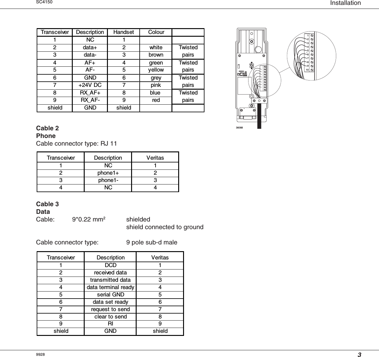
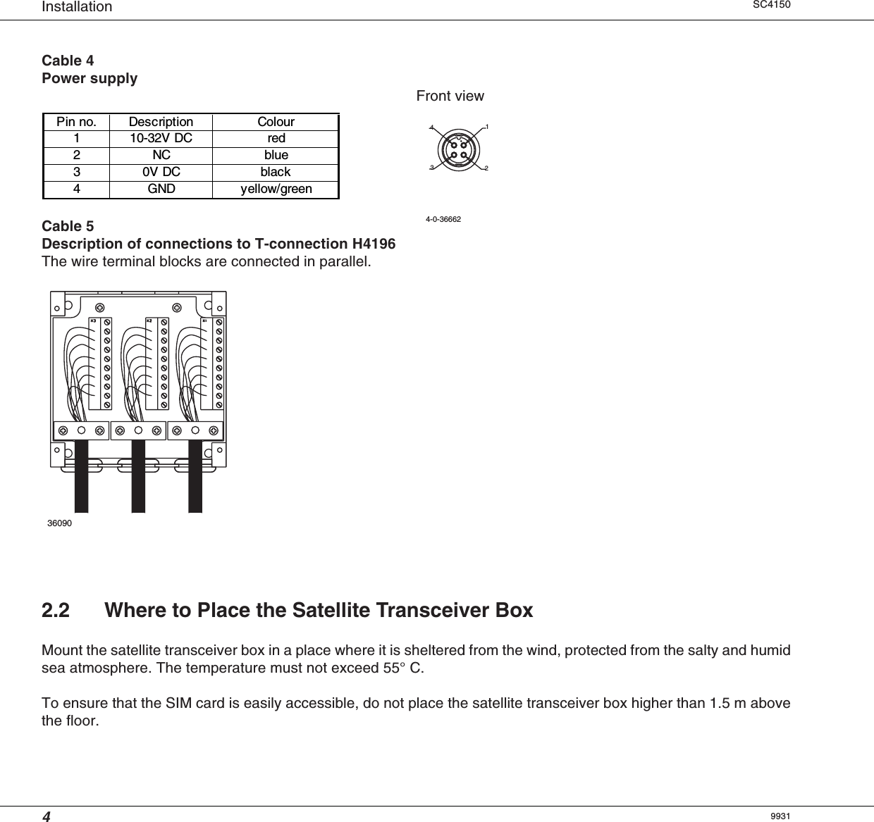
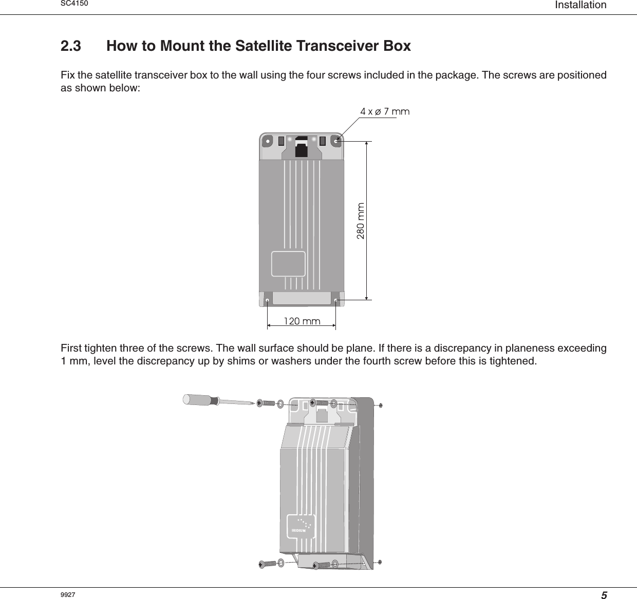
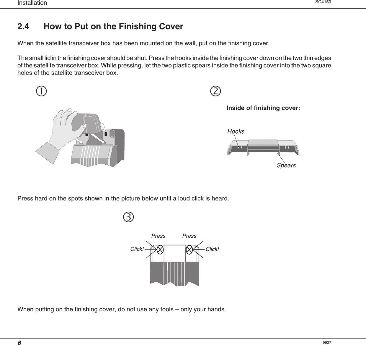
INSTALLATION MANUAL
2.
USER MANUAL
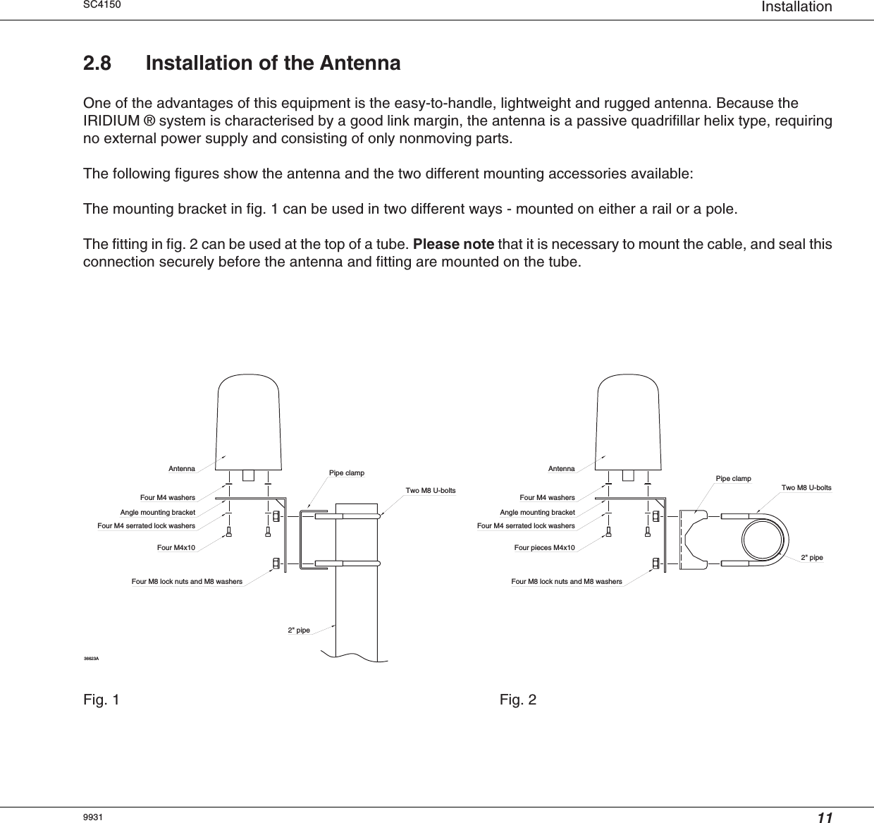
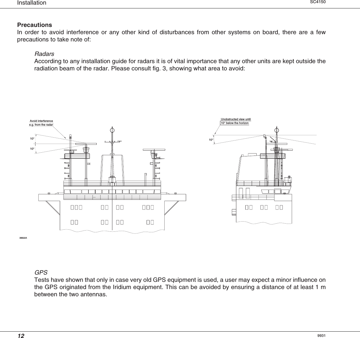
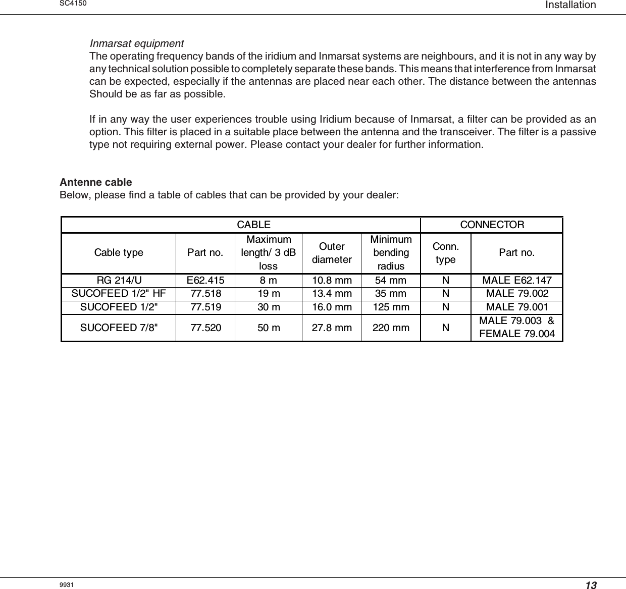
INSTALLATION MANUAL
Navigation menu
Upload a User Manual
Namespaces
Wiki Guide
HTML
PDF
Info
Views
User Manual
Discussion / Help
Navigation