EDAN INSTRUMENTS DX12REDAN PC ECG Receiver Unit User Manual 01 54 106666 2 1 SE 1010 PC ECG x
EDAN INSTRUMENTS, INC. PC ECG Receiver Unit 01 54 106666 2 1 SE 1010 PC ECG x
User Manual

I
About this Manual
P/N: 01.54.106666-21
Release Date: June 2013
© Copyright EDAN INSTRUMENTS, INC. 2008-2013. All rights reserved.
Statement
This manual will help you understand the operation and maintenance of the product better. It is
reminded that the product shall be used strictly complying with this manual. User’s operation
failing to comply with this manual may result in malfunction or accident for which EDAN
INSTRUMENTS, INC. (hereinafter called EDAN) can not be held liable.
EDAN owns the copyrights of this manual. Without prior written consent of EDAN, any
materials contained in this manual shall not be photocopied, reproduced or translated into other
languages.
Materials protected by the copyright law, including but not limited to confidential information
such as technical information and patent information are contained in this manual, the user shall
not disclose such information to any irrelevant third party.
The user shall understand that nothing in this manual grants him, expressly or implicitly, any
right or license to use any of the intellectual properties of EDAN.
EDAN holds the rights to modify, update, and ultimately explain this manual.
Responsibility of the Manufacturer
EDAN only considers itself responsible for any effect on safety, reliability and performance of
the equipment if:
Assembly operations, extensions, re-adjustments, modifications or repairs are carried out by
persons authorized by EDAN, and
The electrical installation of the relevant room complies with national standards, and
The instrument is used in accordance with the instructions for use.
Upon request, EDAN may provide, with compensation, necessary circuit diagrams, and other
information to help qualified technician to maintain and repair some parts, which EDAN may
define as user serviceable.
II
Terms Used in this Manual
This guide is designed to give key concepts on safety precautions.
WARNING
A WARNING label advises against certain actions or situations that could result in personal
injury or death.
CAUTION
A CAUTION label advises against actions or situations that could damage equipment, produce
inaccurate data, or invalidate a procedure.
NOTE
A NOTE provides useful information regarding a function or a procedure.
III
Table of Contents
Chapter 1 Safety Guidance ........................................................................................................... 1
1.1 Intended Use........................................................................................................................ 1
1.2 Warnings and Cautions ........................................................................................................ 1
1.2.1 General Warnings ...................................................................................................... 1
1.2.2 Battery Care Warnings .............................................................................................. 4
1.2.3 General Cautions ....................................................................................................... 5
1.2.4 Operation for Wireless System.................................................................................. 5
1.2.5 Preparation and Operation Warnings (for Exercise ECG) ........................................ 6
1.2.6 Contraindications (for Exercise ECG) ...................................................................... 7
1.3 List of Symbols ................................................................................................................... 8
Chapter 2 Introduction ................................................................................................................ 10
2.1 SE-1010 PC ECG System ................................................................................................. 10
2.2 DP12 ECG Sampling Box of Wired System ..................................................................... 13
2.3 DX12 ECG Sampling Boxes of Wireless System ............................................................. 17
2.4 Features ............................................................................................................................. 20
Chapter 3 Assembling SE-1010 PC ECG System ...................................................................... 22
3.1 Assembling Wired System ................................................................................................ 22
3.2 Assembling Wireless System ............................................................................................ 24
Chapter 4 Installing SE-1010 PC ECG Software ...................................................................... 27
4.1 System Running Environment .......................................................................................... 27
4.1.1 Requirements on the Hardware of the PC ............................................................... 27
4.1.2 Requirements on the Software of the PC ................................................................ 27
4.2 About Installation Window ............................................................................................... 28
Chapter 5 Preparations Before Operation ................................................................................. 29
5.1 Preparing the Patient ......................................................................................................... 29
5.1.1 Instructing the Patient ............................................................................................. 29
5.1.2 Preparing the Skin ................................................................................................... 29
5.2 Connecting the Electrodes of Wired System ..................................................................... 30
5.3 Connecting the Electrodes of Wireless System ................................................................. 31
5.4 Attaching Electrodes (for Resting ECG) ........................................................................... 31
5.4.1 Wilson Lead System ................................................................................................ 32
5.4.2 Frank Lead System .................................................................................................. 33
5.4.3 Attaching Electrodes to the Patient ......................................................................... 33
5.5 Attaching Electrodes to the Patient (for Exercise ECG) ................................................... 35
IV
5.6 Inspection Before Test ....................................................................................................... 37
5.7 Setting DX12 Transmitter (for Wireless System) ............................................................. 38
5.7.1 Keyboard Locking/Unlocking ................................................................................. 40
5.7.2 Menu Settings ......................................................................................................... 41
Chapter 6 Operation Instructions for Resting ECG ................................................................. 42
6.1 Viewing Lead Placement Information .............................................................................. 43
6.2 Selecting a Patient Record to Start a New Test ................................................................. 44
6.3 Entering New Patient Information .................................................................................... 46
6.3.1 Entering New Patient Information Manually .......................................................... 46
6.3.2 Entering Patient Information by Using a Bar Code Reader .................................... 49
6.4 Selecting Sampling Type ................................................................................................... 50
6.5 Sampling Resting ECG ..................................................................................................... 50
6.5.1 Specifying Display Mode ........................................................................................ 51
6.5.2 Specifying Lowpass Filter ...................................................................................... 52
6.5.3 Specifying Gain ....................................................................................................... 52
6.5.4 Specifying Speed ..................................................................................................... 52
6.5.5 Recording ECG Data............................................................................................... 53
6.5.6 Freezing and Previewing ECG ................................................................................ 53
6.5.7 Stopping Sampling Data ......................................................................................... 54
6.5.8 Printing ECG Waves ............................................................................................... 55
6.6 Analyzing ECG Data ......................................................................................................... 55
6.6.1 Analyzing Normal ECG .......................................................................................... 55
6.6.1.1 Viewing the Waveform .................................................................................. 56
6.6.1.2 About the Average Template Window ........................................................... 58
6.6.1.3 About the Detail Information Window .......................................................... 60
6.6.1.4 About the Rhythm Wave Window ................................................................. 61
6.6.1.5 Previewing Normal ECG .............................................................................. 61
6.6.2 Analyzing QT Dispersion ........................................................................................ 63
6.6.2.1 Editing Waveform on the QT Dispersion Screen .......................................... 64
6.6.2.2 About QT Value ............................................................................................. 64
6.6.2.3 Previewing QT Dispersion ............................................................................ 65
6.6.3 Analyzing Frequency ECG ..................................................................................... 66
6.6.3.1 About Two-lead Comparison Window .......................................................... 66
6.6.3.2 About 12-lead Power Spectrum Window ...................................................... 68
6.6.3.3 Previewing Frequency ECG .......................................................................... 68
6.6.4 Analyzing High Frequency ECG ............................................................................ 70
V
6.6.5 Analyzing HRV ....................................................................................................... 72
6.6.5.1 Editing the HRV Data on the Analysis Screen .............................................. 73
6.6.5.2 Editing the HRV Waveform in the Waveform Window ................................ 74
6.6.5.3 Previewing HRV ........................................................................................... 75
6.6.6 Analyzing HRT........................................................................................................ 76
6.6.7 Analyzing Vector ECG ............................................................................................ 78
6.6.7.1 Displaying Vector ECG with All Plane and All Loop ................................... 78
6.6.7.2 Displaying Vector ECG with Frontal Plane and QRS Loop ......................... 81
6.6.7.3 Displaying 3D Vector ECG ........................................................................... 81
6.6.7.4 Previewing Vector ECG ................................................................................ 82
6.6.8 Analyzing Time Vector ECG ................................................................................... 83
6.6.9 Analyzing Signal Averaged ECG ............................................................................ 85
6.6.9.1 About the Time Domain Window ................................................................. 85
6.6.9.2 About the Frequency Domain Window ......................................................... 86
6.6.9.3 Previewing Signal Averaged ECG ................................................................ 87
6.6.10 Printing ECG Reports ........................................................................................... 88
6.6.11 Saving ECG Reports ............................................................................................. 88
6.7 Sampling STAT ECG ........................................................................................................ 89
Chapter 7 Operation Instructions for Exercise ECG ............................................................... 90
7.1 Viewing Lead Placement Information .............................................................................. 90
7.2 Selecting a Patient Record to Start a New Test ................................................................. 91
7.2.1 Setting Target HR .................................................................................................... 92
7.2.2 Setting Normal BP .................................................................................................. 92
7.2.3 Setting a Protocol .................................................................................................... 92
7.2.4 Setting Post J ........................................................................................................... 92
7.2.5 Setting BP Sampling Mode ..................................................................................... 93
7.2.6 Setting BP Triggering Mode ................................................................................... 93
7.2.7 Setting Auto Printing ............................................................................................... 93
7.3 Entering New Patient Information .................................................................................... 93
7.4 Pre-sampling ECG ............................................................................................................ 94
7.5 Pretest Phase ..................................................................................................................... 95
7.5.1 Viewing the Heart Rate and the Blood Pressure ..................................................... 96
7.5.2 Viewing Other Information ..................................................................................... 97
7.5.3 Editing the Waveform ............................................................................................. 97
7.5.4 Printing the Pretest Report ...................................................................................... 99
7.6 Exercise Phase ................................................................................................................... 99
VI
7.7 Recovery Phase ............................................................................................................... 100
7.8 Exiting the Exercise Test ................................................................................................. 100
7.9 About Analysis Screen .................................................................................................... 101
7.9.1 About Summary Screen......................................................................................... 101
7.9.2 About ST Analysis Screen ..................................................................................... 103
7.9.3 About All View Review Screen ............................................................................. 105
7.9.4 About Trend Screen ............................................................................................... 107
7.9.5 About ECG Strip Screen ....................................................................................... 108
7.9.6 Previewing ECG Reports ...................................................................................... 108
7.9.7 Printing ECG Reports ........................................................................................... 109
7.9.8 Saving ECG Reports ............................................................................................. 109
7.9.9 Exiting the Analysis Screen .................................................................................. 109
Chapter 8 Processing Patient Records ..................................................................................... 110
8.1 Searching Patient Records .............................................................................................. 110
8.2 Modifying Patient Records ............................................................................................. 112
8.3 Deleting Records ............................................................................................................. 113
8.3.1 Deleting Patient Records ....................................................................................... 113
8.3.2 Deleting Examination Records of a Patient .......................................................... 113
8.4 Selecting a Patient Record .............................................................................................. 113
8.5 Merging Examination Records ....................................................................................... 114
8.6 Comparing Two Examination Records ........................................................................... 114
8.7 Importing ECG Data into the Data Manager Screen ...................................................... 116
8.8 Exporting ECG Data from the Data Manager Screen ..................................................... 118
8.9 Viewing an Examination Record .................................................................................... 119
Chapter 9 Configuring the System ........................................................................................... 120
9.1 Basic Information Setup .................................................................................................. 120
9.1.1 Setting Basic Information ..................................................................................... 121
9.1.2 Setting ID Mode .................................................................................................... 122
9.1.3 Setting Language ................................................................................................... 122
9.1.4 Specifying the Storage Path of the ECG Data....................................................... 122
9.2 Sample Setup ................................................................................................................... 123
9.2.1 Setting Filter .......................................................................................................... 123
9.2.2 Setting Sampling Time .......................................................................................... 124
9.2.3 Others .................................................................................................................... 124
9.2.4 Selecting Auto Printing When Detecting Arrhythmia ........................................... 125
9.2.5 Setting Background Grid....................................................................................... 125
VII
9.2.6 Setting Anti-aliasing .............................................................................................. 125
9.2.7 Selecting QRS Voice ............................................................................................. 125
9.2.8 Selecting Sequence Mode When Sampling .......................................................... 125
9.3 Device Setup ................................................................................................................... 126
9.3.1 Setting Sampling Device ....................................................................................... 126
9.3.2 Setting Device Type/Mode .................................................................................... 127
9.3.3 Setting COM Port of Sample/Treadmill/BP Monitor ............................................ 127
9.3.4 Setting a Protocol .................................................................................................. 127
9.3.4.1 Creating a New Protocol ............................................................................. 128
9.3.4.2 Modifying a Protocol .................................................................................. 129
9.3.4.3 Deleting a Protocol ...................................................................................... 130
9.3.4.4 Restoring the default protocol ..................................................................... 130
9.3.5 Advanced Setup ..................................................................................................... 130
9.3.5.1 Setting Access Network .............................................................................. 130
9.3.5.2 Setting Barcode ........................................................................................... 131
9.4 Print Setup ....................................................................................................................... 133
9.4.1 Choosing Patient Information to be Printed .......................................................... 133
9.4.2 Choosing Diagnosis Information to be Printed ..................................................... 134
9.4.3 Setting Rhythm Lead............................................................................................. 135
9.4.4 Defining Printing Format ...................................................................................... 135
9.5 Output File Setup ............................................................................................................ 136
9.5.1 File Naming ........................................................................................................... 136
9.5.2 Setting PDF/JPG ................................................................................................... 137
9.5.3 Setting SCP ........................................................................................................... 137
9.5.4 Setting FDA-XML ................................................................................................ 137
9.5.5 Setting DICOM ..................................................................................................... 138
9.5.6 Specifying the Output Path ................................................................................... 138
9.6 Data Maintenance Setup ................................................................................................. 138
9.6.1 Database Rebuild .................................................................................................. 139
9.6.2 Database Backup ................................................................................................... 139
9.7 GDT Setup ...................................................................................................................... 141
9.8 Other Setup ..................................................................................................................... 142
9.8.1 Setting Unit and Color .......................................................................................... 143
9.8.2 Setting System Password ...................................................................................... 143
9.8.3 Setting Wave Width and Grid Width ..................................................................... 143
9.9 Modifying the Glossary................................................................................................... 144
VIII
Chapter 10 Hint Information .................................................................................................... 146
Chapter 11 Cleaning, Care and Maintenance ......................................................................... 148
11.1 Cleaning and Maintaining the Treadmill ....................................................................... 148
11.2 Cleaning and Maintaining the Patient Cable and Reusable Electrodes ........................ 148
11.3 Disinfection ................................................................................................................... 149
11.4 Maintenance of ECG Sampling Box ............................................................................. 149
Chapter 12 Accessories .............................................................................................................. 151
Chapter 13 Warranty & Service ............................................................................................... 153
13.1 Warranty ........................................................................................................................ 153
13.2 Contact information ...................................................................................................... 153
Chapter 14 Recommended Optional Accessories .................................................................... 154
Appendix 1 Technical Specifications ........................................................................................ 156
A1.1 Safety Specifications .................................................................................................... 156
A1.2 Environment Specifications ......................................................................................... 156
A1.3 Physical Specifications ................................................................................................. 157
A1.4 Power Supply Specifications ........................................................................................ 157
A1.5 Performance Specifications .......................................................................................... 157
Appendix 2 EMC Information .................................................................................................. 160
Appendix 3 Abbreviation ........................................................................................................... 165

SE-1010 PC ECG User Manual Safety Guidance
- 1 -
Chapter 1 Safety Guidance
This chapter provides important safety information related to the use of SE-1010 PC ECG.
1.1 Intended Use
SE-1010 PC ECG is a PC-based diagnostic tool intended to acquire, process and store ECG
signals from adult and pediatric patients undergoing stress exercise test or resting test. SE-1010
PC ECG is intended to be used only in hospitals and healthcare facilities by doctors and trained
healthcare professionals. The cardiogram recorded by SE-1010 PC ECG can help users to analyze
and diagnose heart disease. However the ECG with measurements and interpretive statements is
offered to clinicians on an advisory basis only.
WARNING
♦ This system is not designed for intracardiac use or direct cardiac application.
♦ This system is not intended for home use.
♦ This system is not intended for treatment or monitoring.
♦ This system is intended for use on adult and pediatric patients only.
♦ The results given by the system should be examined based on the overall clinical
condition of the patient, and they can not substitute for regular checking.
1.2 Warnings and Cautions
To use the system safely and effectively, firstly be familiar with the operation method of
Windows and read the user manual in detail to be familiar with the proper operation method for
the purpose of avoiding the possibility of system failure. The following warnings and cautions
must be paid more attention to during the operation of the system.
1.2.1 General Warnings
WARNING
1. The system is intended to be used by qualified physicians or personnel professionally
trained. They should be familiar with the contents of this user manual before
operation.
2. Only qualified service engineers can install this equipment, and only service
engineers authorized by the manufacturer can open the shell.

SE-1010 PC ECG User Manual Safety Guidance
- 2 -
WARNING
3. EXPLOSION HAZARD - Do not use the system in the presence of flammable
anesthetic mixtures with oxygen or other flammable agents.
4. SHOCK HAZARD - The power receptacle must be a hospital grade grounded outlet.
Never try to adapt the three-prong plug to fit a two-slot outlet.
5. Only the patient cable and other accessories supplied by the manufacturer can be
used. Or else, the performance and electric shock protection can not be guaranteed.
The system has been safety tested with the recommended accessories, peripherals,
and leads, and no hazard is found when the system is operated with cardiac
pacemakers or other stimulators.
6. Make sure that all electrodes are connected to the patient correctly before operation.
7. Ensure that the conductive parts of electrodes and associated connectors, including
neutral electrodes, do not come in contact with earth or any other conducting objects.
8. If reusable electrodes with electrode gel are used during defibrillation, the system
recovery will take more than 10 seconds. The manufacturer recommends the use of
disposable electrodes at all times.
9. Electrodes of dissimilar metals should not be used; otherwise it may cause a high
polarization voltage.
10. The disposable electrodes can only be used for one time.
11. Do not touch the patient, bed, table or the equipment while using the ECG together
with a defibrillator.
12. Do not touch accessible parts of non-medical electrical equipment and the patient
simultaneously.
13.
The use of equipment that applies high frequency voltages to the patient (including
electrosurgical equipment and some respiration transducers) is not supported and
may produce undesired results. Disconnect the patient data cable from the
electrocardiograph, or detach the leads from the patient prior to performing any
procedure that uses high frequency surgical equipment.
14. Fix attention on the examination to avoid missing important ECG waves.
15. SHOCK HAZARD - Don’t connect non-medical electrical equipment, which has been
supplied as a part of the system, directly to the wall outlet when the non-medical
equipment is intended to be supplied by a multiple portable socket-outlet with an
isolation transformer.

SE-1010 PC ECG User Manual Safety Guidance
- 3 -
WARNING
16. SHOCK HAZARD - Don’t connect electrical equipment, which has not been supplied
as a part of the system, to the multiple portable socket-outlet supplying the system.
17. Do not connect any equipment or accessories that are not approved by the
manufacturer or that are not IEC/EN 60601-1-1 approved to the system. The
operation or use of non-approved equipment or accessories with the system is not
tested or supported, and system operation and safety are not guaranteed.
18. Any non-medical equipment (such as the external printer) is not allowed to be used
within the patient vicinity (1.5m/6ft.).
19. Do not exceed the maximum permitted load when using the multiple portable
socket-outlet(s) to supply the system.
20. Multiple portable socket-outlets shall not be placed on the floor.
21. Do not use the additional multiple portable socket-outlet or extension cord in the
medical electrical system, unless it’s specified as part of the system by manufacturer.
And the multiple portable socket-outlets provided with the system shall only be used
for supplying power to equipment which is intended to form part of the system.
22. Accessory equipment connected to the analog and digital interfaces must be certified
according to the respective IEC/EN standards (e.g. IEC/EN 60950 for data processing
equipment and IEC/EN 60601-1 for medical equipment). Furthermore all
configurations shall comply with the valid version of the standard IEC/EN 60601-1-1.
Therefore anybody, who connects additional equipment to the signal input or output
connector to configure a medical system, must make sure that it complies with the
requirements of the valid version of the system standard IEC/EN 60601-1-1. If in
doubt, consult our technical service department or your local distributor.
23. Connecting any accessory (such as external printer) or other device (such as the
computer) to this electrocardiograph makes a medical system. In that case, additional
safety measures should be taken during installation of the system, and the system
shall provide:
a) Within the patient environment, a level of safety comparable to that provided by
medical electrical equipment complying with IEC/EN 60601-1, and
b) Outside the patient environment, the level of safety appropriate for non-medical
electrical equipment complying with other IEC or ISO safety standards.
24. All the accessories connected to system must be installed outside the patient vicinity,
if they do not meet the requirement of IEC/EN 60601-1.

SE-1010 PC ECG User Manual Safety Guidance
- 4 -
WARNING
25. You should purchase computer, printer, treadmill, ergometer, BP monitor and bar code
reader from the manufacturer. Otherwise, the manufacturer will not be held
responsible for the maintenance of the PC hardware, operating system and other
accessories.
26. If multiple instruments are connected to a patient, the sum of the leakage currents
may exceed the limits given in the IEC/EN 60601-1 and may pose a safety hazard.
Consult your service personnel.
27. Connecting to other devices may decrease the antistatic gradation of the system
during operation.
1.2.2 Battery Care Warnings
WARNING
1. Improper operation may cause the internal battery to be hot, ignited or exploded, and
it may lead to the decrease of the battery capacity. It is necessary to read the user
manual carefully and pay more attention to warning messages.
2. Batteries of the same model and specification as manufacture configuration should be
used.
3. DANGER OF EXPLOSION -- Do not reverse the anode and the cathode when
installing the battery.
4. Do not heat or splash the battery or throw it into fire or water.
5. Do not destroy the battery; do not pierce battery with a sharp object such as a needle;
do not hit with a hammer, step on or throw or drop to cause strong shock; do not
disassemble or modify the battery.
6. When leakage or foul smell is found, stop using the battery immediately. If your skin or
cloth comes into contact with the leakage liquid, cleanse it with clean water at once. If
the leakage liquid splashes into your eyes, do not wipe them. Irrigate them with clean
water first and go to see a doctor immediately.
7. Properly dispose of or recycle the depleted battery according to local regulations.
8. Remove the battery from the transmitter if the system won’t be used for a long time.

SE-1010 PC ECG User Manual Safety Guidance
- 5 -
1.2.3 General Cautions
CAUTION
1. Avoid liquid splash and excessive temperature. The temperature must be kept
between 5 ºC and 40 ºC during operation, and it should be kept between -20 ºC and
55 ºC
during transportation and storage.
2. Do not use the equipment in a dusty environment with bad ventilation or in the
presence of corrosive.
3. Make sure that there is no intense electromagnetic interference source around the
equipment, such as radio transmitters or mobile phones etc. Attention: large medical
electrical equipment such as electrosurgical equipment, radiological equipment and
magnetic resonance imaging equipment etc. is likely to bring electromagnetic
interference.
4. Ruptured fuse must only be replaced with that of the same type and rating as the
original.
5. The device and accessories are to be disposed of according to local regulations after
their useful lives. Alternatively, they can be returned to the dealer or the manufacturer
for recycling or proper disposal. Batteries are hazardous waste. Do NOT dispose of
them together with house-hold garbage. At the end of their lives hand the batteries
over to the applicable collection points for the recycling of waste batteries. For more
detailed information about recycling of this product or battery, please contact your
local Civic Office, or the shop where you purchased the product.
6. Federal (U.S.) law restricts this device to sale by or on the order of a physician.
1.2.4 Operation for Wireless System
WARNING
1. Make sure that there is no intense electromagnetic interference source around the
wireless system.
2. Do not open the battery cover of the transmitter during operation.

SE-1010 PC ECG User Manual Safety Guidance
- 6 -
1.2.5 Preparation and Operation Warnings (for Exercise ECG)
WARNING
1. Test the safety stop (mushroom type) and safety stop (cord type) of the treadmill
before using the system.
2. During the exercise test, ensure that there are at least 2 experienced physicians
present. One of them observes the patient and deals with the emergency.
3. Make sure that there is necessary valid first-aid equipment such as defibrillators,
blood-pressure meters etc, and necessary valid medication in the exercise test room.
4. Turn off the system power and disconnect the power cord from the wall outlet after
using the system.
5. Make sure that the power is turned off and the power cord is disconnected from the
AC socket before defibrillation.
6. Keep the four feet of the machine on the ground and make sure that it’s stably
working.
7. The treadmill must be powered by the specific power outlet.
8. Examine the treadmill/ergometer carefully before using it.
9. The patient undergoing the exercise test should wear suitable clothes and shoes.
10. Keep hands, hair, jewelry, and loose clothing away from moving parts.
11. Don’t let the patient stand on the running belt when starting the treadmill. The patient
should stand on the foot rails and hold the handrails during start-up. Wait until the
running belt is moving before placing feet on the belt.
12. To avoid the static electricity, the patient should not wear loose clothing or clothing
(such as nylon) that easily produces static electricity.
13. Stop exercising immediately when the patient feels uncomfortable or something
abnormal in the operation.
14. Press down the safety stop (mushroom type) or pull out the safety stop (cord type) to
stop the treadmill immediately when an emergency happens.

SE-1010 PC ECG User Manual Safety Guidance
- 7 -
1.2.6 Contraindications (for Exercise ECG)
Absolute Contraindications:
1. Acute MI (within 2 days)
2. High-risk unstable angina
3. Hemodynamic compromise caused by uncontrolled cardiac arrhythmia
4. Symptomatic severe aortic stenosis
5. Heart failure with clinic episode uncontrolled
6. Acute pulmonary embolus or pulmonary infarction
7. Acute myocarditis or pericarditis
8. The patient opposes the test.
Relative Contraindications:
1. Left main coronary stenosis
2. Moderate stenotic valvular heart disease
3. Serum Electrolyte abnormalities
4. Severe hypertension (systolic blood pressure >200 mmHg or diastolic blood
pressure >110 mmHg)
5. Tachyarrhythmias or bradyarrhythmias
6. Hypertrophic cardiomyopathy
7. Patients can not cooperate because of mental impairment or physical disability
8. High-degree AV block
SE-1010 PC ECG User Manual Safety Guidance
- 8 -
1.3 List of Symbols
Equipment or part of CF type with defibrillator proof
Caution
Consult Instructions for Use
Recycle
Part Number
Serial Number
Date of Manufacture
Manufacturer
Authorized Representative in the European Community
The symbol indicates that the device complies with the
European Council Directive 93/42/EEC concerning
medical devices.
It indicates that the device should be sent to the special
agencies according to local regulations for separate
collection after its useful life.
Rx only (U.S.)
Federal (US) law restricts this device to sale by or on the
order of a physician
SE-1010 PC ECG User Manual Safety Guidance
- 9 -
Class Ⅱ
Transmission Status Indicator of Bluetooth
Burglar Lock
Power Supply Indicator of DX12 Receiver
(for DX12 Transmitter)
(for DX12 Receiver)
This device complies with Part 15 of the FCC Rules.
Operation is subject to the following two conditions:
(1) this device may not cause harmful interference, and
(2) this device must accept any interference received,
including interference that may cause undesired
operation.

SE-1010 PC ECG User Manual Introduction
- 10 -
Chapter 2 Introduction
SE-1010 PC ECG has similar functions with an ordinary electrocardiograph. ECG data can be
sampled, analyzed and stored in a PC, and it can be saved in PDF, Word, BMP or JPG format.
ECG waves can be frozen and reviewed. Auto measurement and diagnosis are available, and the
diagnosis template can be edited. SE-1010 PC ECG can also be invocated by Smart ECG Net
version 1.3 or above.
When a patient with coronary heart disease runs, the added heart load will cause myocardium
hypotension, and then the ECG will change abnormally. Therefore, with the function of exercise
ECG, SE-1010 PC ECG can also be used to diagnose concealed coronary heart disease and
atypical angina pectoris, prescribe the workload for patients with myocardial infarction before
they leave hospital, and assess the effect of the treatment. With SE-1010 PC ECG, doctors’
workload can be reduced greatly.
NOTE:
1. The exercise ECG function is optional. It is available only if you purchased this
function.
2. The pictures and windows in this manual are for reference only.
2.1 SE-1010 PC ECG System
SE-1010 PC ECG system includes the following equipment:
1. PC ECG software
2. ECG Sampling Box (wired or wireless system)
3. Patient Cable
4. Electrodes
5. Sentinel
6. USB Cable
SE-1010 PC ECG User Manual Introduction
- 11 -
Wired System of SE-1010 PC ECG System
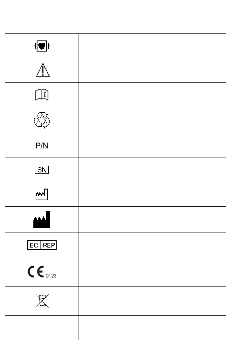
1. Resting ECG of Wired System
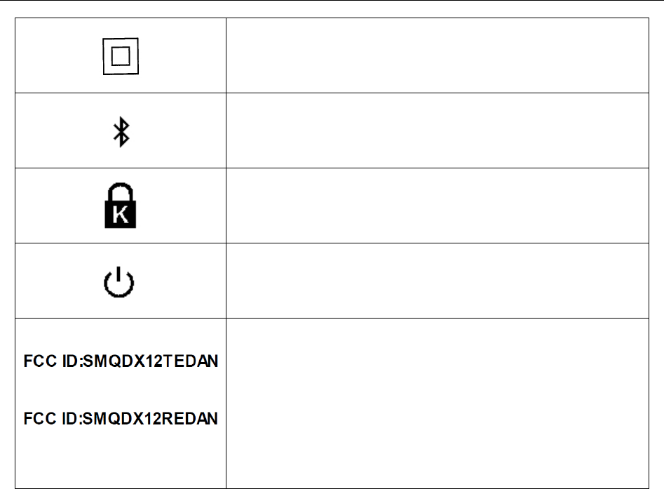
2. Exercise ECG of Wired System
Patient Cable
USB Cable
Resting
ECG Cable
PC (Manually
Configured)
Printer (Manually
Configured)
DP12 ECG
Sampling Box
Patient
Patient Cable
USB Cable
Exercise
ECG Cable
Treadmill or Ergometer
(Manually Configured)
PC (Manually
Configured)
Printer (Manually
Configured)
DP12 ECG
Sampling Box
Patient
Serial
Cable
BP Monitor
(Manually
Configured)
Exercise
ECG Cable
SE-1010 PC ECG User Manual Introduction
- 12 -
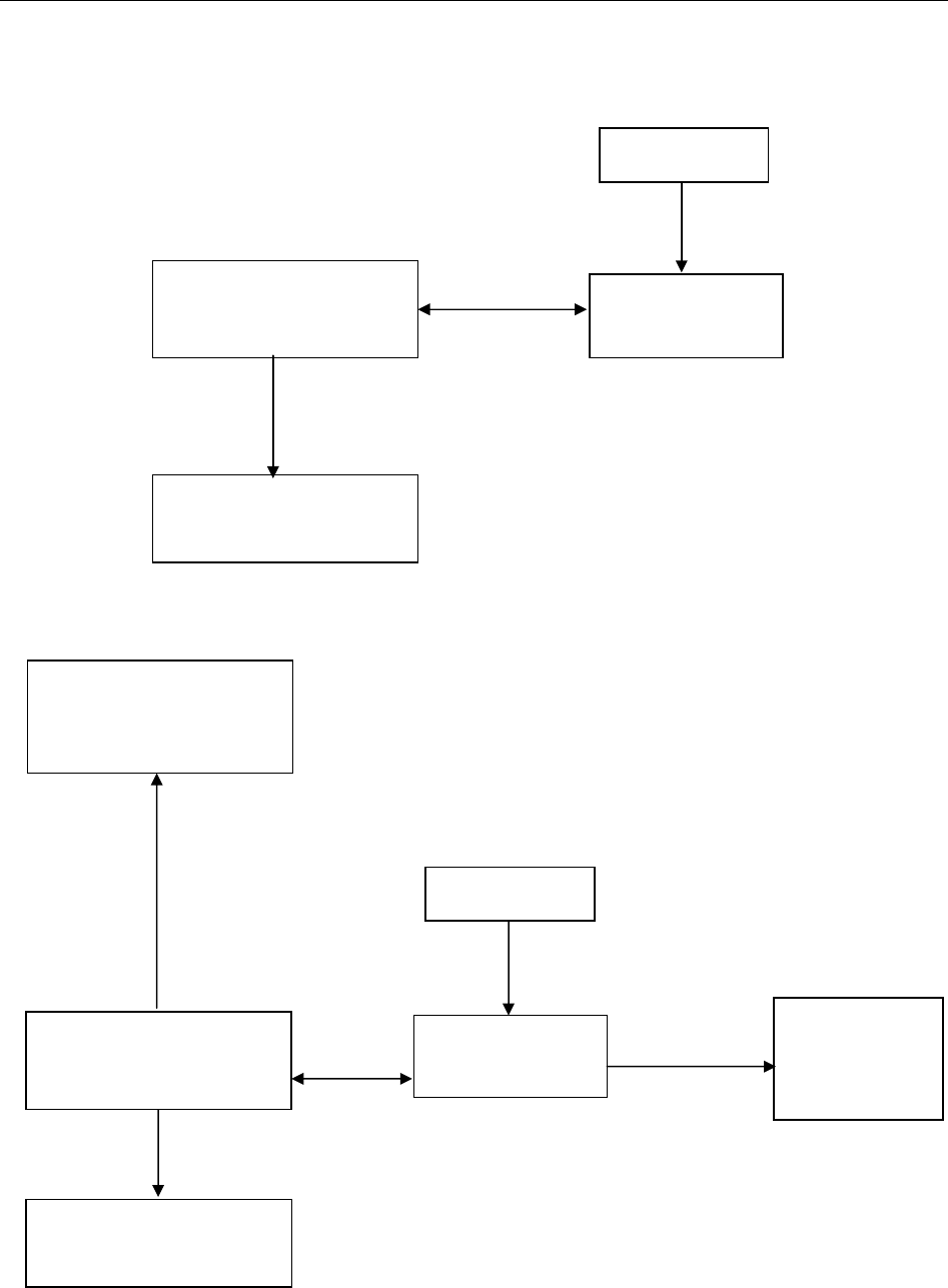
Wireless System of SE-1010 PC ECG System
The DX12 device which consists of transmitter and receiver has passed FCC certification. This
device complies with Part 15 of the FCC Rules. Operation is subject to the following two
conditions: (1) this device may not cause harmful interference, and (2) this device must accept
any interference received, including interference that may cause undesired operation.
1. Resting ECG of Wireless System
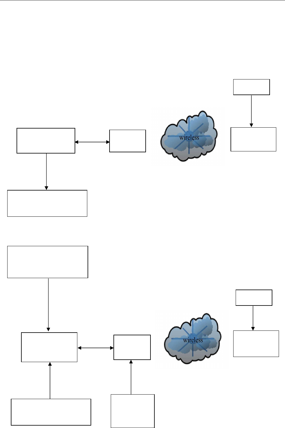
2. Exercises ECG of Wireless System
DX12
Transmitter
Patient
DX12
Receiver
PC (Manually
Configured)
Printer (Manually
Configured)
USB Cable
Patient Cable
Resting
ECG Cable
Treadmill or Ergometer
(Manually Configured)
DX12
Transmitter
Patient
DX12
Receiver
Serial
Cable
PC (Manually
Configured)
Printer (Manually
Configured)
USB Cable
Patient Cable
BP Monitor
(Manually
Configured
Exercise
ECG Cable
Exercise
ECG Cable

SE-1010 PC ECG User Manual Introduction
- 13 -
3. FCC Statement
This equipment has been tested and found to comply with the limits for a Class B digital
device, pursuant to part 15 of FCC Rules. These limits are designed to provide reasonable
protection against harmful interference in a residential installation. This equipment generates
and can radiate radio frequency energy and, if not installed and used in accordance with the
instructions, may cause harmful interference to radio communications. However, there is no
guarantee that interference will not occur in a particular installation. If this equipment does
cause harmful interference to radio or television reception, which can be determined by turning
the equipment off and on, the user is encouraged to try to correct
The interference by one or more of the following measures:
1. Reorient or relocate the receiving antenna.
2. Increase the separation between the equipment and receiver.
3. Connect the equipment into an outlet on a circuit different from that to which the
receiver is connected.
4. Consult the dealer or an experienced radio/TV technician for help.
This device complies with Part 15 of FCC Rules. Operation is subject to the following two
conditions:
1. This device may not cause harmful interference,
2. And this device must accept any interference received, including interference that
may cause undesired operation.
NOTE: The manufacturer is not responsible for any radio or TV interference caused by
unauthorized modifications to this equipment. such modifications could void
the user’s authority to operate this equipment.
WARNING
The system should be installed by a qualified service engineer. Do not power on the
system until all cables are properly connected and verified.
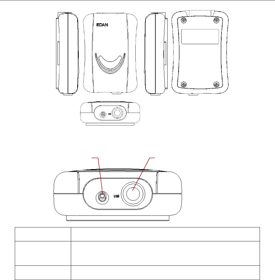
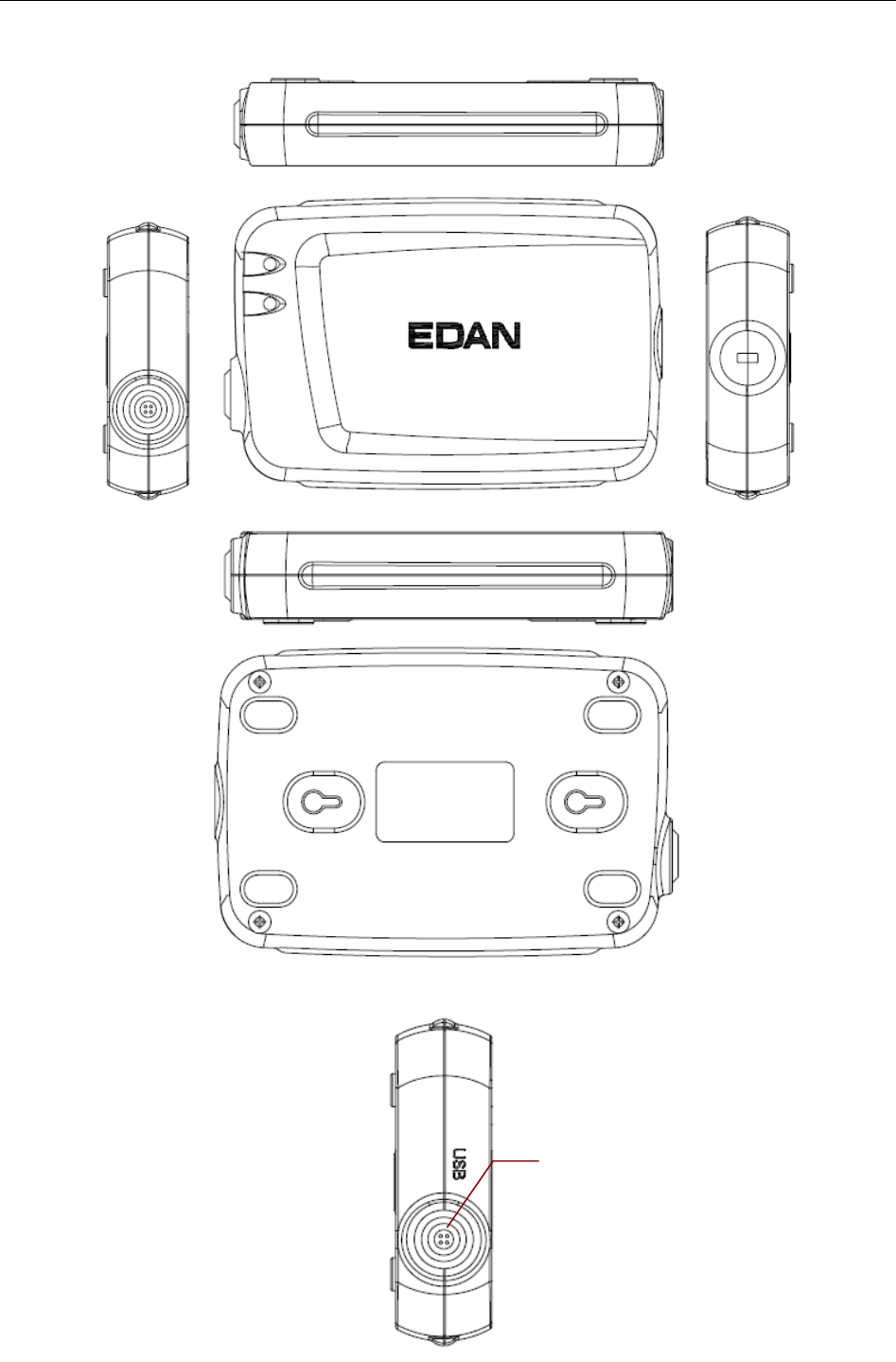
2.2 DP12 ECG Sampling Box of Wired System
DP12 ECG Sampling Box Appearance
SE-1010 PC ECG User Manual Introduction
- 14 -
Front Panel
Name Explanation
Lamp When the ECG sampling box is powered by the PC, the lamp
will be lit.
USB Socket Connecting to the USB socket of the PC with a USB cable
Lamp
USB Socket
SE-1010 PC ECG User Manual Introduction
- 15 -
USB Socket
Definitions of corresponding pins:
Pin Signal Pin Signal
1 GND 6 GND
2 VCC 7 GND
3 QRS 8 GND
4 GND 9 D-
5 GND 10 D+
WARNING
1. When the computer connected to the USB cable is powered on, do not connect the
USB cable to the DP12 ECG sampling box; when the system is powered on, do not
disconnect the USB cable from the ECG sampling box.
2. It is not necessary or recommended to regularly disconnect the USB cable from the
DP12 ECG sampling box. Disconnect the USB cable from the PC if necessary.
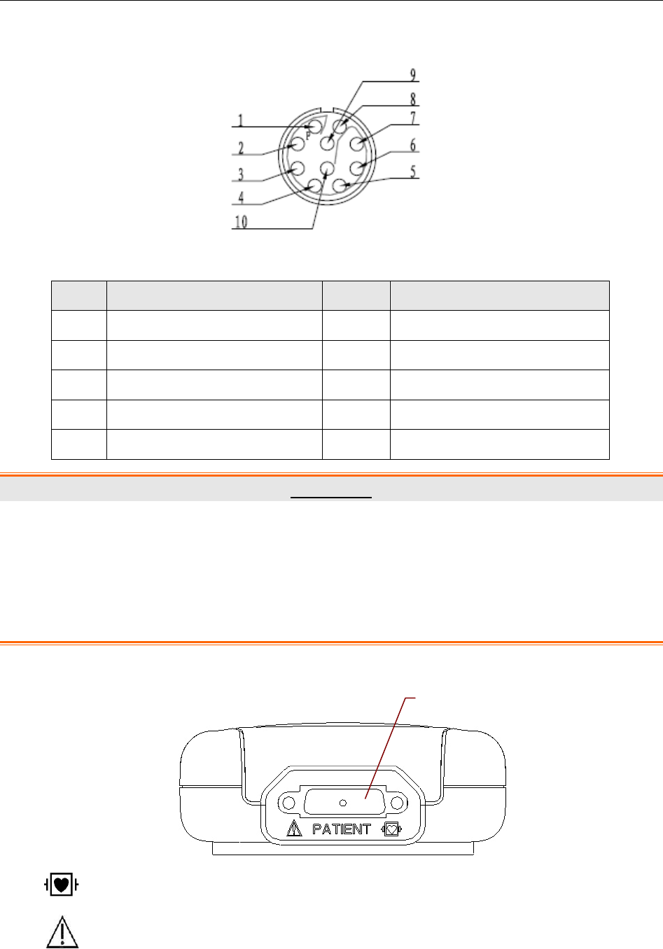
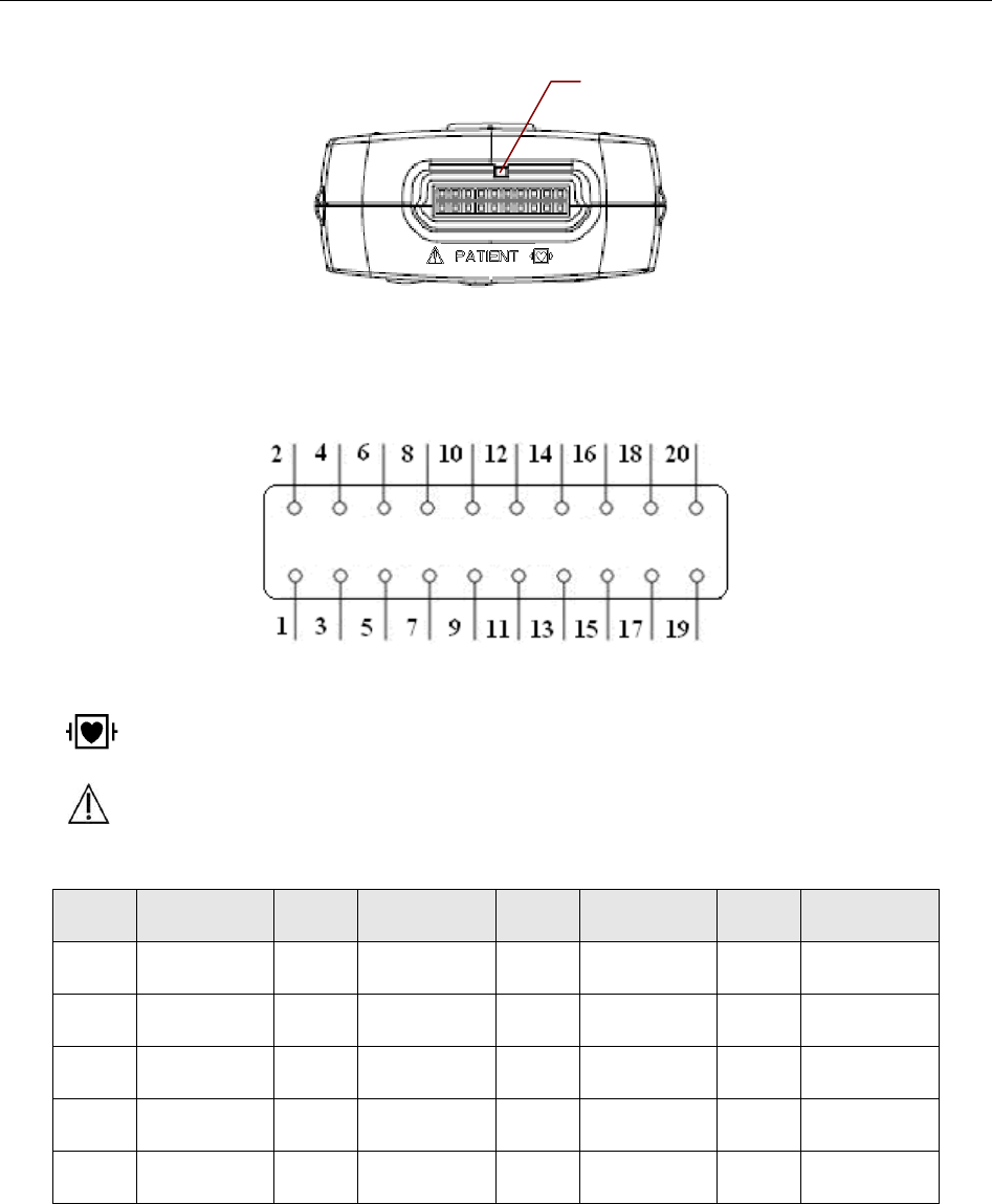
Back Panel
: Applied part of type CF with defibrillator proof
: Caution
Patient Cable Socket
SE-1010 PC ECG User Manual Introduction
- 16 -
Patient Cable Socket
Definitions of corresponding pins:
Pin Signal Pin Signal Pin
Signal
1 C2 / V2 6 SH 11 F / LL
2 C3 / V3 7 NC 12 C1 / V1
or NC
3 C4 / V4 8 NC 13 C1 / V1
4 C5 / V5 9 R / RA 14 RF (N) /RL
or NC
5 C6 / V6 10 L / LA 15 RF (N) / RL
NOTE: The left side of “/” is European standard, and the right side is American standard.
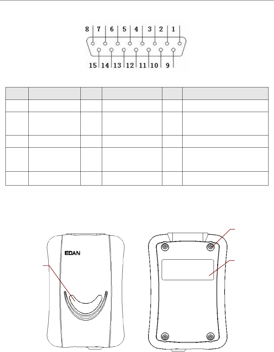
Top Panel and Bottom Panel
Decorative
Chip
Label
Screw
SE-1010 PC ECG User Manual Introduction
- 17 -
WARNING
1. Accessory equipment connected to the analog and digital interfaces must be
certified according to the respective IEC/EN standards (e.g. IEC/EN 60950 for data
processing equipment and IEC/EN 60601-1 for medical equipment). Furthermore all
configuration shall comply with the valid version of the standard IEC/EN 60601-1-1.
Therefore anybody, who connects additional equipment to the signal input or output
connector to configure a medical system, must make sure that it complies with the
requirements of the valid version of the system standard IEC/EN 60601-1-1. If in
doubt, consult our technical service department or your local distributor.
2. If multiple instruments are connected to a patient, the sum of the leakage currents
may exceed the limits given in the IEC/EN 60601-1 and may pose a safety hazard.
Consult your service personnel.
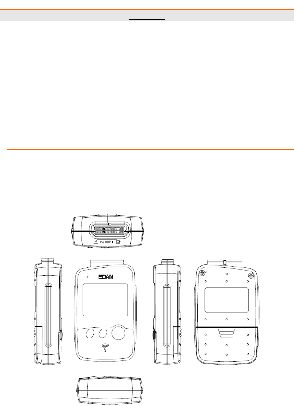
2.3 DX12 ECG Sampling Boxes of Wireless System
DX12 Transmitter Appearance
SE-1010 PC ECG User Manual Introduction
- 18 -
Front Panel
Patient Cable Socket
:Applied part of type CF with defibrillator proof
:Caution
Definitions of corresponding pins:
Pin Signal Pin Signal Pin Signal Pin Signal
1 NC 6 C5/V5 11 NC 16 L/LA
2 F/LL 7 NC 12 C2/V2 17 NC
3 NC 8 C4/V4 13 NC 18 R/RA
4 C6/V6 9 NC 14 C1/V1 19 NC
5 NC 10 C3/V3 15 NC 20 N/RL
NOTE: The left side of “/” is European standard, and the right side is American standard.
Patient Cable Socket
SE-1010 PC ECG User Manual Introduction
- 19 -
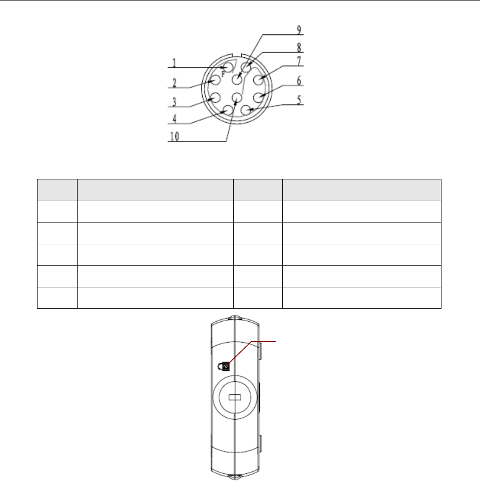
DX12 Receiver Appearance
USB Socket
USB Socket
SE-1010 PC ECG User Manual Introduction
- 20 -
Definitions of corresponding pins:
Pin Signal Pin Signal
1 GND 5 GND
2 VCC 6 GND
3 QRS 7 GND
4 GND 8 D-
5 GND 10 D+
2.4 Features
1. Powerful functions, friendly windows and easy operation
2. 3/6/12-channel ECG waves are displayed and printed simultaneously
3. ECG waves can be frozen and reviewed
4. Supporting auto measurement and diagnosis
5. Measurement point adjustment and re-analysis, manual measurement with an electronic
ruler of high precision
6. Perfect data management and processing functions
Lock

SE-1010 PC ECG User Manual Introduction
- 21 -
7. Reports can be printed in PDF, Word, JPG or BMP format
8. Supporting multi-language
9. Updated to be a network electrocardiograph, transmitting ECG data over LAN or WAN or
INTERNET
10. Automatic baseline adjustment for optimal printing
11. High performance filters guarantee stable ECG waveforms
12. Real-time analysis, real-time displaying and printing 12-lead simultaneous ECG
waveforms
13. Nine analysis functions including Normal ECG, Frequency ECG, High Frequency ECG,
QT Dispersion, Vector ECG, Time Vector ECG, HRT analysis, HRV analysis and Signal
Averaged ECG (Only for resting ECG)
The following features are only for the exercise test function of SE-1010 PC ECG
1. Automatically controlling and adjusting the speed and the elevation of the treadmill
2. Supporting many kinds of treadmills and ergometers
3. Providing classical exercise protocols; new exercise protocols can be added to the system
4. ST segment analysis and measurement of 12-lead waveforms while sampling ECG; ST
position is adjustable while sampling ECG
5. Providing summaries, ST analysis, wave reviews and trends
6. Providing specific statistic data of each lead in each stage
7. Providing average waves of each lead in each stage for you to observe the changes of ST
segments among different stages
SE-1010 PC ECG User Manual Assembling SE-1010 PC ECG System
- 22 -
Chapter 3 Assembling SE-1010 PC ECG System
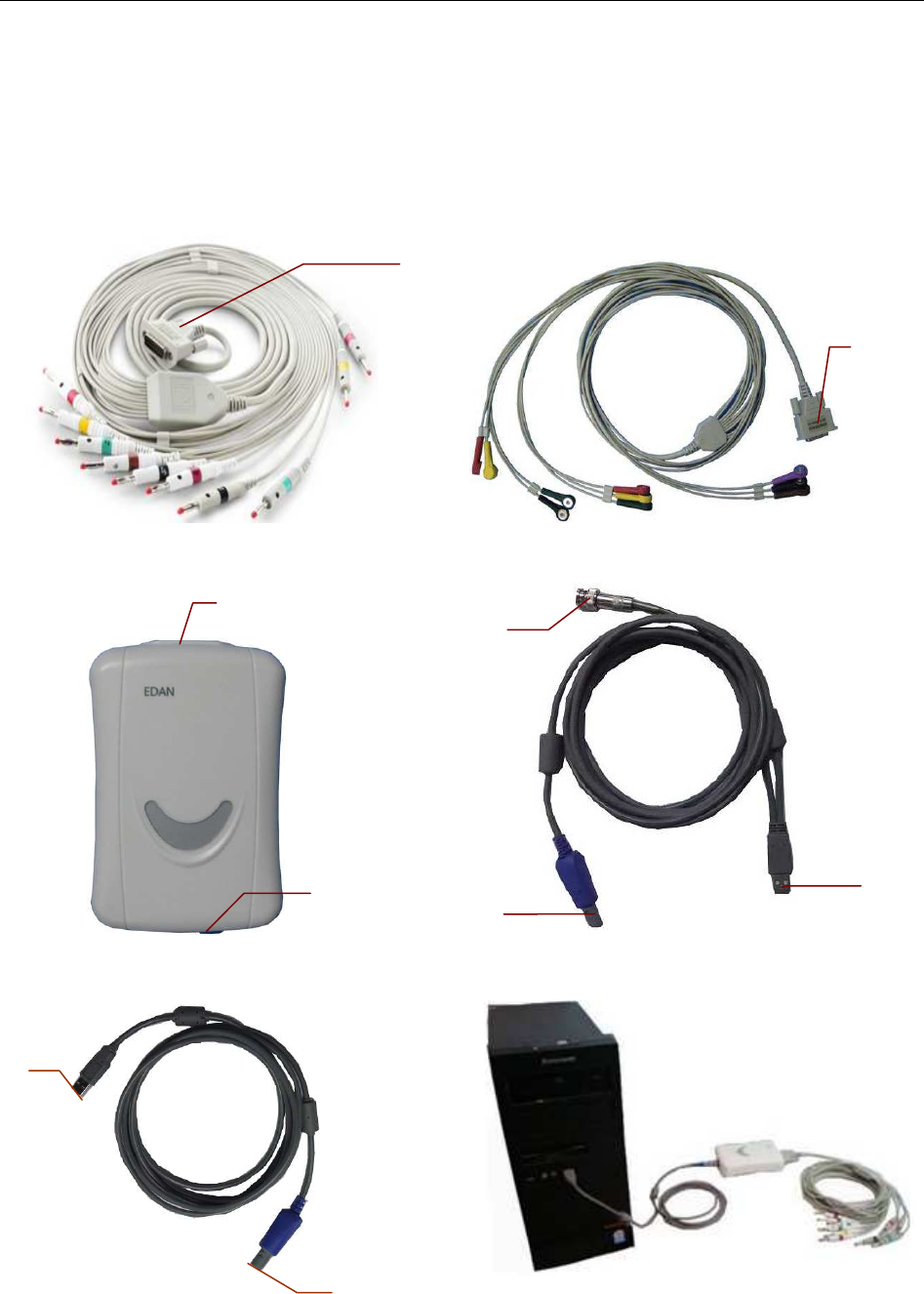
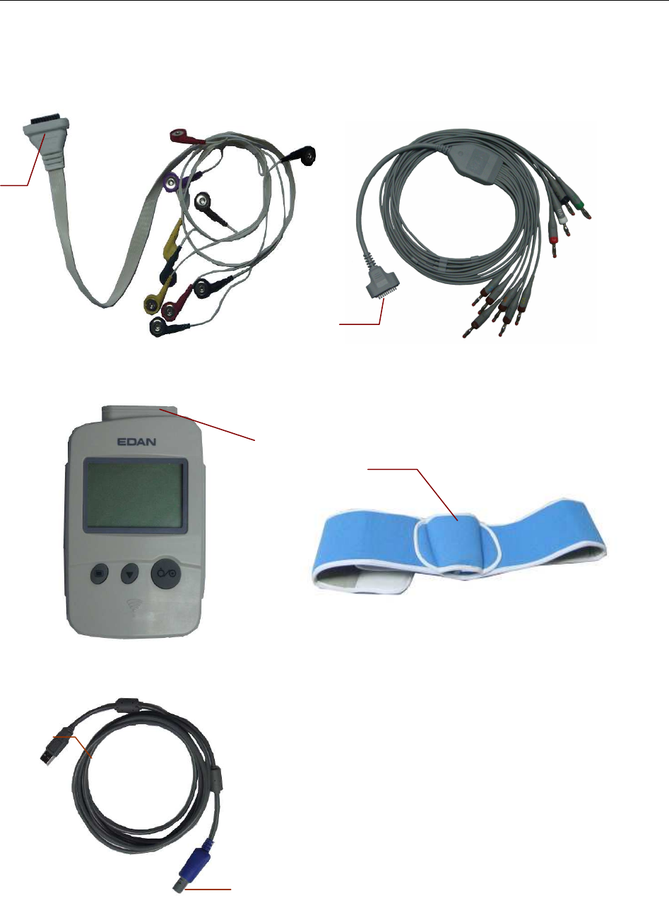
3.1 Assembling Wired System
Patient Cable for Resting ECG Patient Cable for Exercise ECG
DP12 ECG Sampling Box Exercise ECG Cable
Resting ECG Cable Assembly Drawing
3
4
2
1
7
5
8
6
9

SE-1010 PC ECG User Manual Assembling SE-1010 PC ECG System
- 23 -
For Resting ECG of wired system,
♦ Insert plug 1 of the patient cable into socket 3 of DP12 ECG sampling box.
♦ Insert plug 8 of the cable into socket 4 of DP12 ECG sampling box.
♦ Insert plug 9 of the cable into the USB socket of the PC.
♦ Connect a printer to the PC.
♦ Insert the Sentinel into the USB socket of the PC.
♦ Make sure that the above parts are properly connected, and then connect the PC, and the
printer to the power supply.
For Exercise ECG of wired system,
1. Insert plug 2 of the patient cable into socket 3 of DP12 ECG sampling box.
2. Insert plug 7 of the cable into socket 4 of DP12 ECG sampling box.
3. Insert plug 5 of the cable into the USB socket of the PC.
4. Connect plug 6 of the cable to the BP monitor.
5. Connect a treadmill or an ergometer to the PC.
6. Connect a printer to the PC.
7. Insert the Sentinel into the USB socket of the PC.
8. Make sure that the above parts are properly connected, and then connect the PC,
treadmill/ergometer and printer to the power supply.
WARNING
1. Use a special grounded socket to get accurate voltage and current.
2. When using a laptop with a two-prong plug, please connect a grounded printer to
avoid power interference.
3. Only stress BP monitors can be used.
SE-1010 PC ECG User Manual Assembling SE-1010 PC ECG System
- 24 -
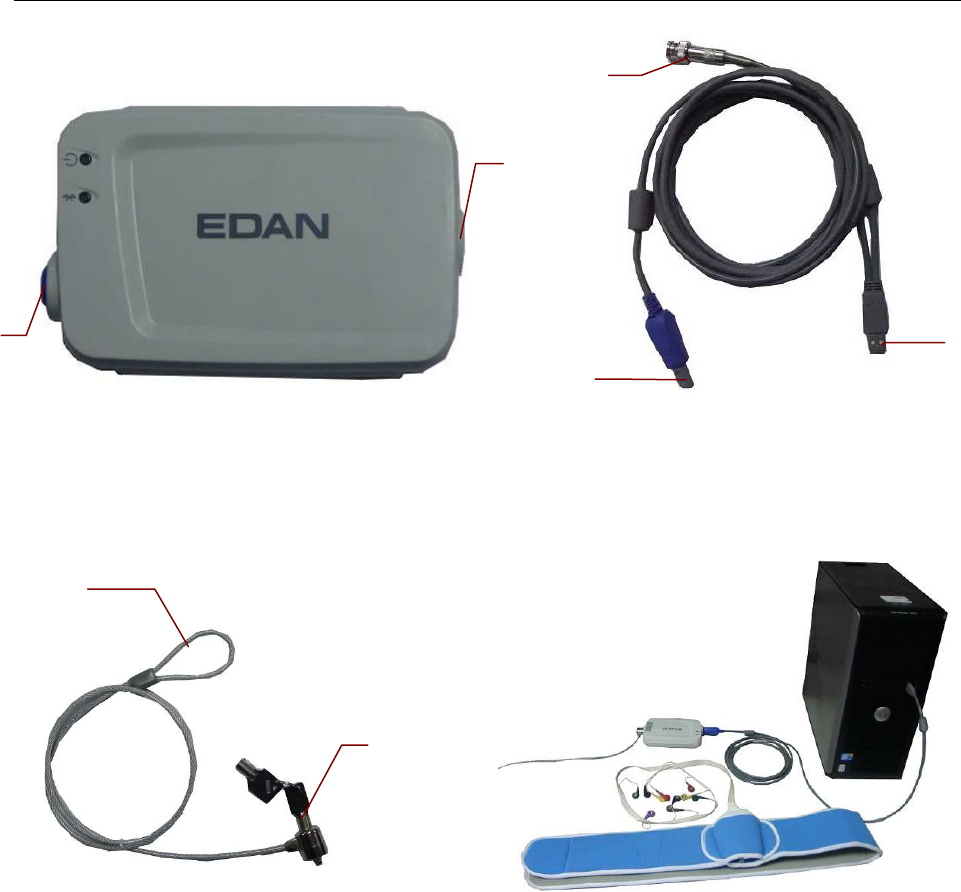
3.2 Assembling Wireless System
Patient Cable Patient Cable
DX12 Transmitter DX12 Belt
Resting ECG Cable
1
2
3
5
4
1
SE-1010 PC ECG User Manual Assembling SE-1010 PC ECG System
- 25 -
DX12 Receiver Exercise ECG Cable
Burglar Lock Assembly Drawing
For Resting ECG of wireless system,
1. Insert plug 1 of the patient cable into socket 2 of DX12 transmitter.
2. Insert plug 4 of the cable into socket 6 of DX12 receiver.
3. Insert plug 5 of the cable into the USB socket of the PC.
4. Connect a printer to the PC.
5. Insert the Sentinel into the USB socket of the PC.
6. Make sure that the above parts are properly connected, and then connect the PC, and the
printer to the power supply.
For Exercise ECG of wireless system,
1. Insert plug 1 of the patient cable into socket 2 of DX12 transmitter.
2. Insert DX12 transmitter into pocket 3 of DX12 belt, and then wear the belt around the waist.
3. Insert plug 8 of the cable into socket 6 of the DX12 receiver.
11
12
6
9
8
10
7

SE-1010 PC ECG User Manual Assembling SE-1010 PC ECG System
- 26 -
4. Insert plug 9 of the cable into the USB socket of the PC.
5. Connect plug 10 of the cable to the BP monitor.
6. Connect a treadmill or an ergometer to the PC.
7. Connect a printer to the PC.
8. Insert the Sentinel into the USB socket of the PC.
9. Make sure that the above parts are properly connected, and then connect the PC,
treadmill/ergometer and printer to the power supply.
WARNING
1. Use a special grounded socket to get accurate voltage and current.
2. When using a laptop with a two-prong plug, please connect a grounded printer to
avoid power interference.
3. Only stress BP monitors can be used.

SE-1010 PC ECG User Manual Installing SE-1010 PC ECG Software
- 27 -
Chapter 4 Installing SE-1010 PC ECG Software
4.1 System Running Environment
4.1.1 Requirements on the Hardware of the PC
CPU: Pentium P4, Celeron D 310 or above
System Memory (RAM): 512MB or above
Main Board Recommend the main board of Intel chipset
Hard Disk: 40G or above
Printer: ink jet printer of more than 600dpi or laser printer
Recommend HP2035, HP2010、CANON iP1980
Display:
17” TFT (Resolution: 1024×768, 1280*1024, 1366*768) or
19” TFT (1440×900 resolution), 16 bit actual color, regular
icon and font setup
Others: CD-ROM (24 × or above)
4.1.2 Requirements on the Software of the PC
1. Windows XP PROFESSIONAL SP2/SP3, Windows Vista (32/64 bit) or Windows 7 (32/64
bit)
2. MSDE2000 (Microsoft SQL Server 2000 Desktop Engine) or Microsoft SQL Server 2005
Express
CAUTION
1. Ensure that there is no other database software in the PC in which our software will be
installed.
2. Ensure that there is a graphic driver installed in the PC. Otherwise, the displayed ECG
waves may be abnormal.
SE-1010 PC ECG User Manual Installing SE-1010 PC ECG Software
- 28 -
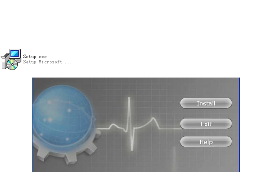
4.2 About Installation Window
Insert the installation CD into CD-ROM, and double-click on Setup.exe
to open the following installation window.
Figure 4-1 Installation Window
Click on the Install button to install PC ECG. Click on the Next button continually during
installation.
After installing PC ECG, click on the Install button in the installation window. Then the
Environment Detection window pops up. Check the installing status of all the components. If
the Environment Detection window shows that a certain component needs to be installed, please
install it manually.
NOTE: During the installation of SQL Server 2005 Express in Windows 7/Vista, only if
Add user to the SQL Server Administrator role is selected, can the database
be available.
Click on the Help button to see the installation guide.
For details on installing PC ECG software, please refer to SE-1010 PC ECG Installation Guide.

SE-1010 PC ECG User Manual Preparations Before Operation
- 29 -
Chapter 5 Preparations Before Operation
5.1 Preparing the Patient
5.1.1 Instructing the Patient
Before attaching the electrodes, greet the patient and explain the procedure. Explaining the
procedure decreases the patient’s anxiety. Reassure the patient that the procedure is painless.
Privacy is important for relaxation. When possible, prepare the patient in a quiet room or area
where others can’t see the patient. Make sure that the patient is comfortable. The more relaxed
the patient is, the less the ECG will be affected by noise.
5.1.2 Preparing the Skin
Thorough skin preparation is very important. The skin is a poor conductor of electricity and
frequently creates artifacts that distort the ECG signals. By performing methodical skin
preparation, you can greatly reduce the possibility of noise caused by muscle tremor and baseline
drift, ensuring high-quality ECG waves. There is natural resistance on the skin surface due to dry,
dead epidermal cells, oils and dirt.
To prepare the skin
1. Shave hair from electrode sites, if necessary. Excessive hair prevents a good connection.
2. Wash the area thoroughly with soap and water.
3. Dry the skin to increase capillary blood flow and to remove the dead, dry skin cells and oils.
4. Use the disposable frosting film in the standard accessory list to get good ECG waveform.
NOTE: Rub the skin with a gauze pad to increase capillary blood flow if you don’t operate
the steps above.
SE-1010 PC ECG User Manual Preparations Before Operation
- 30 -
5.2 Connecting the Electrodes of Wired System
WARNING
The performance and electric shock protection can be guaranteed only if the original
patient cable and electrodes of the manufacturer are used.
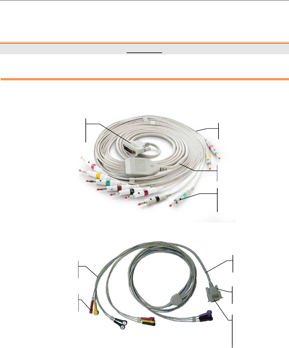
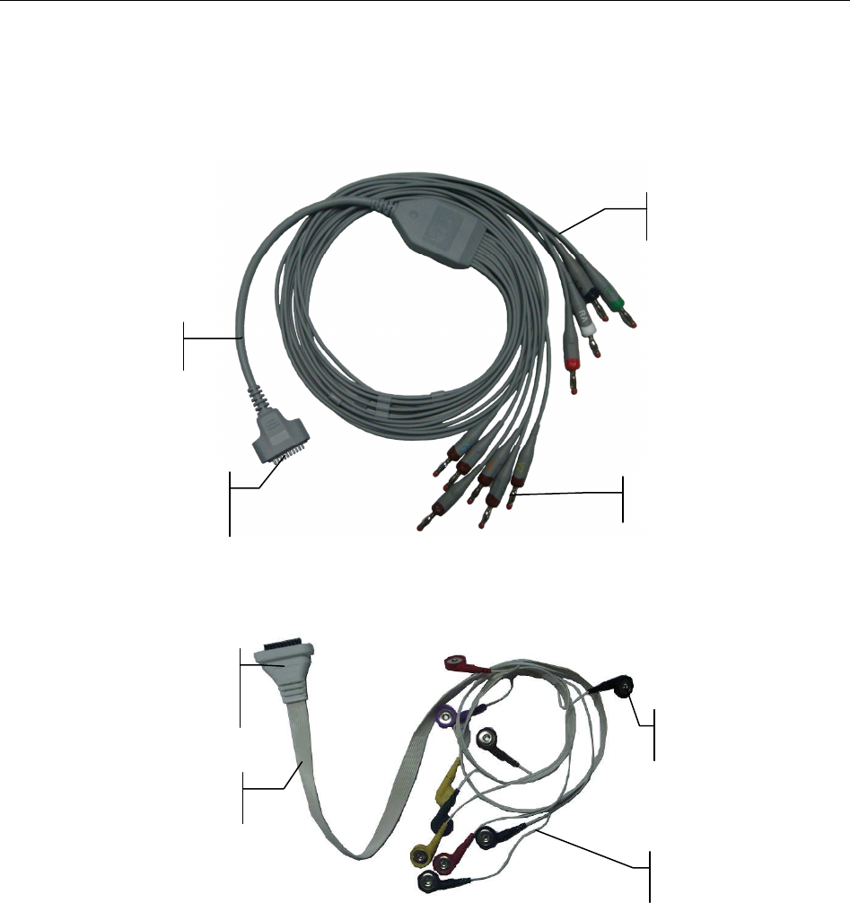
The patient cable includes main cable and lead wires which can be connected to electrodes
according to the colors and identifiers.
Patient Cable for Resting ECG
Patient Cable for Exercise ECG
1. Connect the patient cable to DP12 ECG sampling box of wired system. For details, please
refer to Section 3.1, “Assembling Wired System”.
2. Align all lead wires of the patient cable to avoid twisting, and connect the lead wires to the
corresponding electrodes according to the colors and identifiers. Firmly attach them.
Connecting to
Electrodes
Lead Wires
Connecting to
ECG Sampling Box
Main Cable
Main Cable
Lead Wires
Connecting to the
ECG Sampling Box
Screw
Connecting to Electrodes
SE-1010 PC ECG User Manual Preparations Before Operation
- 31 -
5.3 Connecting the Electrodes of Wireless System
The patient cable includes main cable and lead wires which can be connected to electrodes
according to the colors and identifiers.
Patient Cable for Resting ECG
Patient Cable for Exercise ECG
1. Connect the patient cable to DX12 transmitter of wireless system. For details, see
Section 3.2, “Assembling Wireless System”.
2. Align all lead wires of the patient cable to avoid twisting, and connect the lead wires to
the corresponding electrodes according to the colors and identifiers. Firmly attach them.
5.4 Attaching Electrodes (for Resting ECG)
The identifiers and color codes of electrodes used comply with IEC/EN requirements. In order to
avoid incorrect connections, the electrode identifiers and color codes are specified in Table 5-1.
Moreover the equivalent codes according to American requirements are given in Table 5-1 too.
Electrode Connector
Lead Wires
Connecting to DX12
transmitter
Main Cable
Main Cable
Lead Wires
Connecting to the
ECG Sampling Box
Connecting to Electrodes
SE-1010 PC ECG User Manual Preparations Before Operation
- 32 -
Table 5-1 Electrodes and Their Identifiers and Color Codes
European American
WILSON FRANK Identifier Color Code Identifier Color Code
Right arm Right arm R Red RA White
Left arm Left arm L Yellow LA Black
Right leg Right leg N or RF Black RL Green
Left leg Left leg F Green LL Red
Chest 1 I C1 White/Red V1 Brown/Red
Chest 2 E C2 White/Yellow
V2 Brown/Yellow
Chest 3 C C3 White/Green
V3 Brown/Green
Chest 4 A C4 White/Brown
V4 Brown/Blue
Chest 5 M C5 White/Black
V5 Brown/Orange
Chest 6 H C6 White/Violet
V6 Brown/Violet
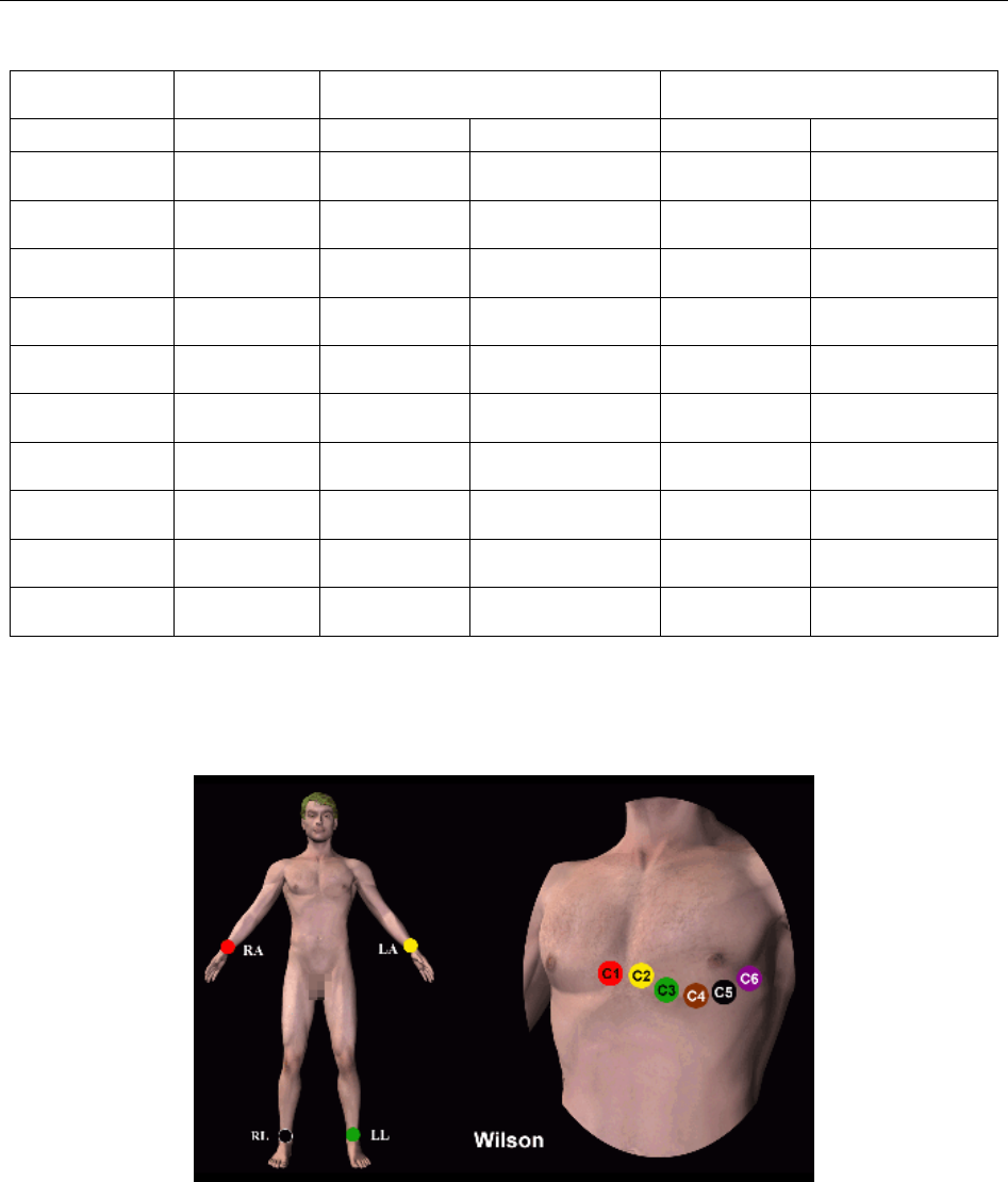
5.4.1 Wilson Lead System
C1: Fourth intercostal space at the right border of the sternum
C2: Fourth intercostal space at the left border of the sternum
C3: Fifth rib between C2 and C4
C4: Fifth intercostal space on the left midclavicular line
C5: Left anterior axillary line at the horizontal level of C4
C6: Left midaxillary line at the horizontal level of C4

SE-1010 PC ECG User Manual Preparations Before Operation
- 33 -
5.4.2 Frank Lead System
FRANK lead system is usually adopted when PC ECG is used to produce VCG. The conventional
letter designations for the electrodes and their respective positions are:
E/C2: at the front midline
M/C5: at the back midline
I/C1: at the right mid-axillary line
A/C4: at the left mid-axillary line
C/C3: at 45º angle between the front midline and the left mid-axillary line
F: on the left leg
N: on the right leg
H: on the back of the neck
The first five electrodes (E, M, I, A and C) are all located at the same transverse level --
approximately at the interspace between the fourth rib and the fifth rib.
5.4.3 Attaching Electrodes to the Patient
For Limb Electrodes:
Reed
Connecting to a Lead Wire
Clamp
SE-1010 PC ECG User Manual Preparations Before Operation
- 34 -
1. Clean the electrode area which is in a short distance above the ankle or the wrist with
alcohol.
2. Daub the electrode area on the limb with gel evenly.
3. Place a small amount of gel on the metal part of the limb electrode clamp.
4. Connect the electrode to the limb, and make sure that the metal part is placed on the
electrode area above the ankle or the wrist.
5. Attach all limb electrodes in the same way.
For Chest Electrodes:
♦ Clean the electrode area on the chest surface with alcohol.
♦ Daub the round area of 25mm in diameter on each electrode area with gel evenly.
♦ Place a small amount of gel on the brim of the chest electrode’s metal cup.
♦ Place the electrode on the chest electrode area and squeeze the suction bulb. Unclench it
and the electrode is adsorbed on the chest.
♦ Attach all chest electrodes in the same way.
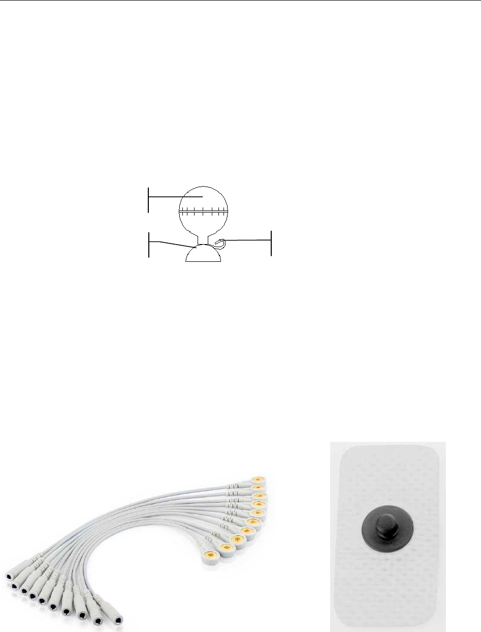
Chest Electrode (Only for C5 in Frank Lead System):
Snap/Banana Socket Adapter: Disposable Electrode:
Disposable Electrode Connection:
♦ Connect the snap/banana socket adapter to the lead wire.
♦ Connect the snap/banana socket adapter to the disposable electrode.
♦ Clean the electrode area at the back midline with 75% alcohol.
Suction Bulb
Connecting to a Lead Wire
Cup
SE-1010 PC ECG User Manual Preparations Before Operation
- 35 -
♦ Attach the disposable electrode to the electrode area at the back midline.
The quality of ECG waveform will be affected by the contact resistance between the patient and
the electrode. In order to get a high-quality ECG, the skin-electrode resistance must be minimized
while connecting electrodes.
WARNING
1. Make sure that all electrodes are connected to the patient correctly before operation.
2. Make sure that the conductive parts of electrodes and associated connectors,
including neutral electrodes, do not come in contact with earth or any other
conducting objects.
3. The disposable electrodes can only be used for one time.
5.5 Attaching Electrodes to the Patient (for Exercise ECG)
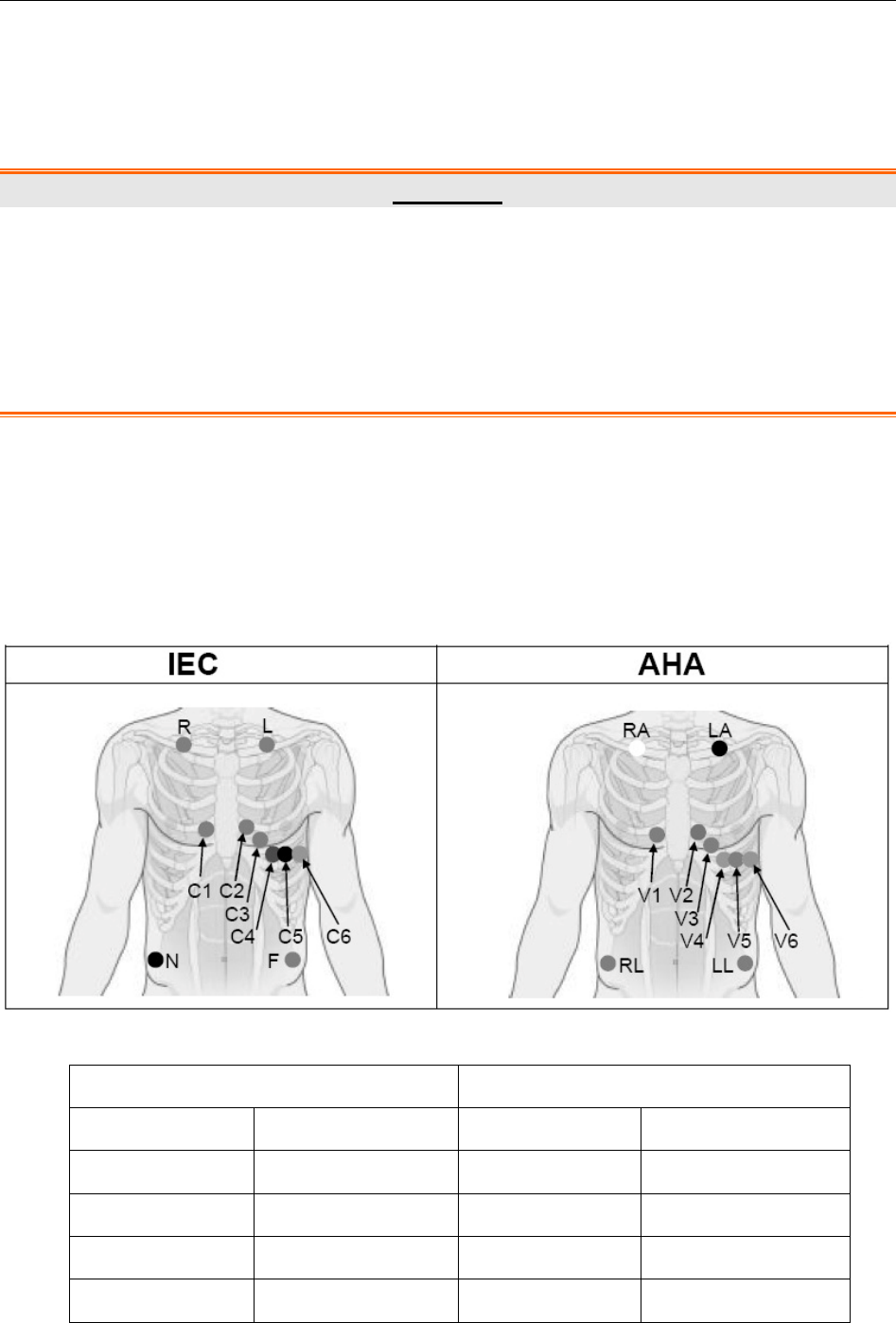
The identifiers and color codes of electrodes used comply with IEC/EN requirements. In order to
avoid incorrect connections, the electrode identifiers and color codes are specified in Table 5-2.
Moreover the equivalent codes according to American requirements are given in Table 5-2 too.
Table 5-2 Electrodes and their identifiers and color codes
European American
Electrodes Color code Electrodes Color code
R Red RA White
L Yellow LA Black
N or RF Black RL Green
F Green LL Red

SE-1010 PC ECG User Manual Preparations Before Operation
- 36 -
C1 White/Red V1 Brown/Red
C2 White/Yellow V2 Brown/Yellow
C3 White/Green V3 Brown/Green
C4 White/Brown V4 Brown/Blue
C5 White/Black V5 Brown/Orange
C6 White/Violet V6 Brown/Violet
The Precordial Electrodes’ Positions on Body Surface:
C1: Fourth intercostal space at the right border of the sternum
C2: Fourth intercostal space at the left border of the sternum
C3: Fifth rib between C2 and C4
C4: Fifth intercostal space on the left midclavicular line
C5: Left anterior axillary line at the horizontal level of C4
C6: Left midaxillary line at the horizontal level of C4
The Extremity Electrodes’ Positions on Body Surface:
R/L: below the right/left clavicle
N/F: below the right/left rib
The quality of ECG waveform will be affected by the contact resistance between the patient
and the electrode. In order to get a high-quality ECG, the skin-electrode resistance must be
minimized while connecting electrodes.
Electrodes Connection:
1. Align all lead wires of the patient cable to avoid twisting, and connect the disposable
electrodes to the lead wires.
2. Clean the electrode areas on the body surface with 75% alcohol.
3. Attach the disposable electrodes to the electrode sites.
NOTE: The quality and the placement of the electrode will directly influence the quality
of exercise ECG. The wrong placement and use of electrodes will cause
incorrect analysis results.
WARNING
1. Make sure that all electrodes are connected to the patient correctly before operation.
2. Make sure that the conductive parts of electrodes and associated connectors,
including neutral electrodes, do not come in contact with earth or any other
conducting objects.
3. The disposable electrodes can only be used for one time.

SE-1010 PC ECG User Manual Preparations Before Operation
- 37 -
5.6 Inspection Before Test
In order to avoid safety hazards and get good ECG records, the following inspection procedure is
recommended before operation.
1. Environment:
1. Make sure that there is no electromagnetic interference source around the equipment,
especially large medical electrical equipment such as electrosurgical equipment, radiological
equipment, magnetic resonance imaging equipment etc. Switch off these devices when
necessary.
2. Keep the examination room warm to avoid muscle action voltages in ECG signals caused by
cold.
2. Power Supply:
1. Check whether the power cord is connected well. The grounded outlet should be used.
3. Patient Cable:
2. Check whether the patient cable is connected to the ECG sampling box firmly, and keep it far
away from the power cord.
4. Electrodes:
3. Check whether all electrodes are connected to lead wires of the patient cable correctly.
4. Ensure that the electrodes do not contact.
5. Patient:
5. The patient should not come into contact with conducting objects such as earth, metal parts
etc.
6. Ensure the patient is warm and relaxed, and breathes calmly.
WARNING
1. The system is intended to be used by qualified physicians or personnel professionally
trained. They should be familiar with the contents of this user manual before
operation.
2. Before connecting the device to the power line, make sure that the voltage and
frequency ratings of your power line match those indicated on the device label. For
details, see Appendix 1, “Technical Specifications”.
3. Before use, the system, patient cable, electrodes etc. should be checked.
Replacement should be taken if there is any evident defectiveness or aging symptom
which may impair the safety or the performance.
SE-1010 PC ECG User Manual Preparations Before Operation
- 38 -
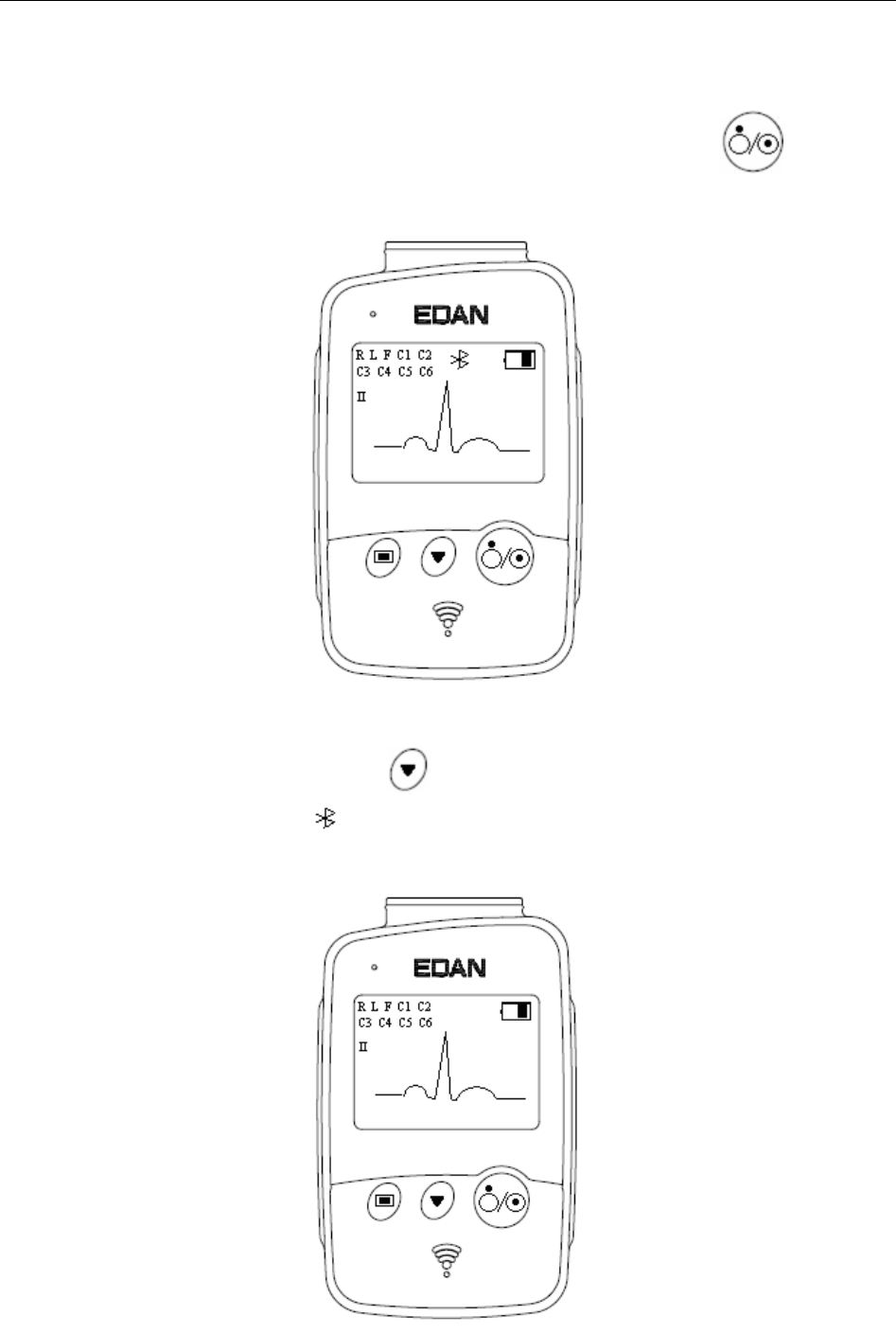
5.7 Setting DX12 Transmitter (for Wireless System)
Switch on DX12 receiver and install batteries on DX12 transmitter. Press to start up
DX12 transmitter, and then the company information and the main screen will be displayed.
Figure 5-1 Main Screen
When the main screen is displayed, press to switch the leads.
If the Bluetooth connection icon is not displayed on the main screen, you have to match the
device manually. Operation instructions are as follows:
SE-1010 PC ECG User Manual Preparations Before Operation
- 39 -
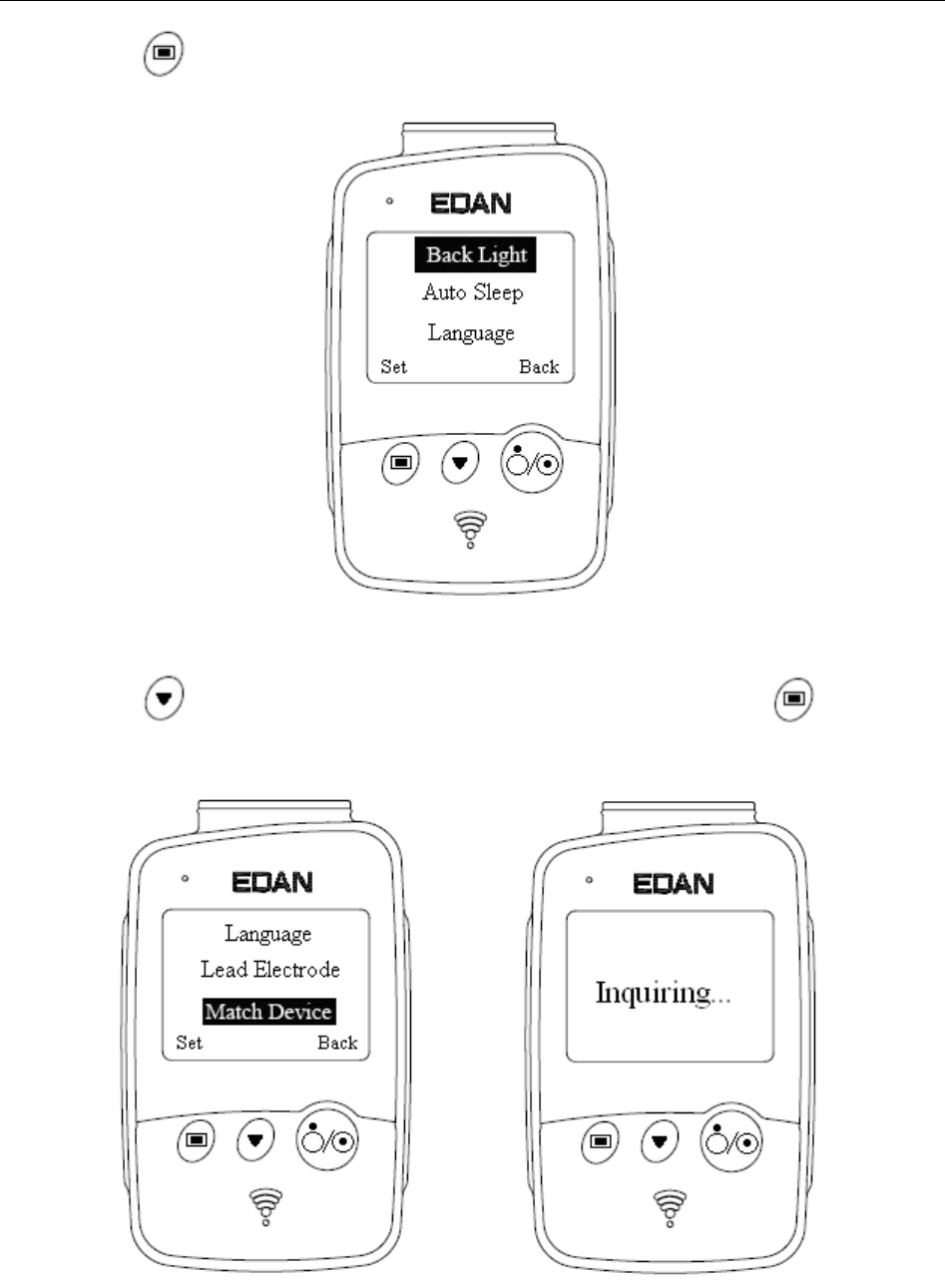
1) Press to enter the menu screen.
Figure 5-2 Menu Screen
2) Press to display Match Device item in black, and then press to open the
screen with a prompt “Inquiring…”.
SE-1010 PC ECG User Manual Preparations Before Operation
- 40 -
3) When the receiver is found, the address of DX12 receiver will be displayed on the screen
in 10 seconds. Press to start up the Bluetooth connection. The Bluetooth connection
will be displayed on the main screen of DX12 transmitter and the Bluetooth status
indicator illuminates in kelly when DX12 transmitter and DX12 receiver are matched
successfully. The Bluetooth status indicator blinks when a data transmission builds
between DX12 transmitter and DX12 receiver. The system will return to the previous
menu if no DX12 receiver is found.
NOTE: Select the receiver address displayed in the PC ECG software when receiving
more than one addresses. For details, please refer to Section 9.3 “Device Setup”.
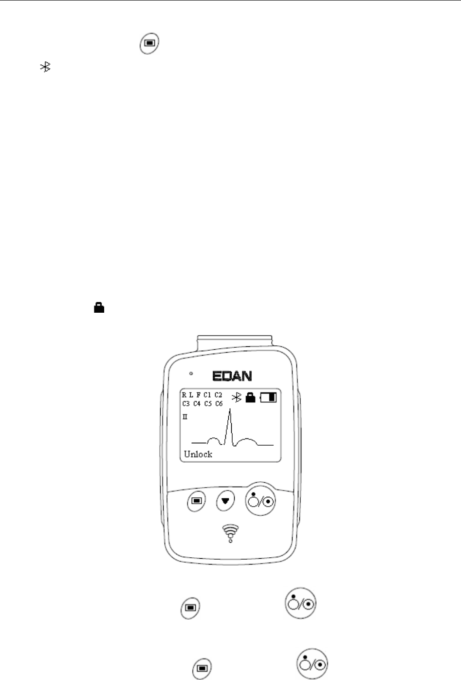
5.7.1 Keyboard Locking/Unlocking
If no operation is taken, the keyboard will be locked automatically in 8 seconds. If the previous
screen is the menu screen, it will return to the main screen after the keyboard is locked
automatically.
When the keyboard is locked, a prompt unlock will be displayed on the left bottom of the main
screen and an icon will be displayed on the top right.
When the keyboard is locked, press , and then press in 1.2 seconds to unlock the
keyboard.
When the keyboard is unlocked, press , and then press in 1.2 seconds to lock the
keyboard manually.
SE-1010 PC ECG User Manual Preparations Before Operation
- 41 -
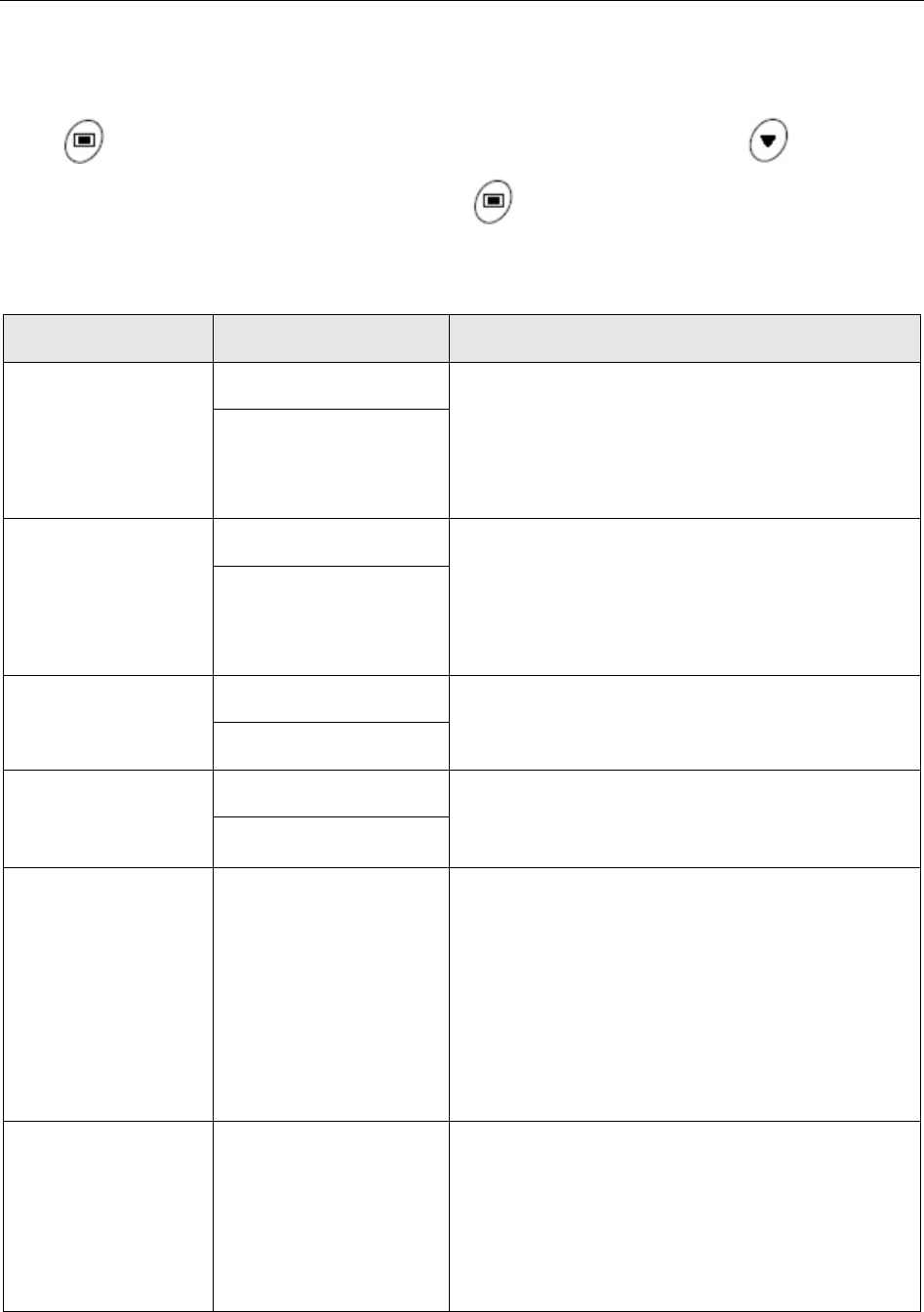
5.7.2 Menu Settings
Press on the main screen to enter the menu screen (Figure 5-2). Press on the menu
screen to display an item in black, and then press to enter the setting screen of this item.
Table 5-3 Menu
Menu Option Description
Back Light
On Select On to turn on the backlight of LCD
screen.
Select Off to turn off the backlight of LCD
screen.
Off
Auto Sleep
On Select On to display Sleeping on the screen
and make DX12 transmitter be in low power
consumption mode after lead off for 5 minutes.
Select Off to turn off auto sleep function.
Off
Language English You can select English or Chinese.
Chinese
Lead Electrode IEC You can select IEC or AHA.
AHA
Match Device
Inquiring……
Address of DX12
receiver
No device found.
Try again later.
Inquiring……
…………
……will be displayed (for 10
seconds) to search DX12 receiver. The address
of DX12 receiver will be displayed (for 8
seconds) if a matching DX12 receiver is found.
No device found. Try again later will be
displayed (for 1 second) if no matching DX12
receiver is found.
Device Information
Software version:1.0
ID:0016a400035D
EDAN
2010.04.20
You can see the related information, such as
software version, ID, address of DX12 receiver,
manufacture and release time about the device.
NOTE: The device information is for
reference only.
SE-1010 PC ECG User Manual Operation Instructions for Resting ECG
- 42 -
Chapter 6 Operation Instructions for Resting ECG
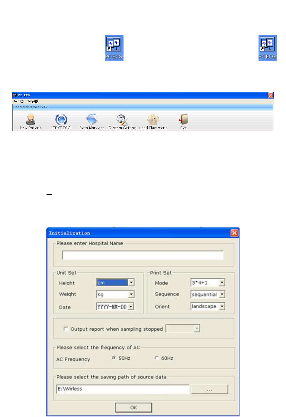
Double-click on the shortcut icon
on the desktop to display the main screen. is
the desktop icon for SE-1010 PC ECG.
NOTE: Do not use other software when using PC ECG software.
Figure 6-1 Toolbar of Main Screen
The toolbar contains six buttons. From left to right, they are New Patient, STAT ECG, Data
Manager, System Setting, Lead Placement and Exit.
Below the toolbar, the software name, version number and copyright information can be seen.
Click on Help (H) to see the help information.
Click on the Exit button on the main screen to exit the system.
If you use PC ECG software for the first time, the following window will be displayed.
Figure 6-2 Initial Window
SE-1010 PC ECG User Manual Operation Instructions for Resting ECG
- 43 -
You can set the unit, print, frequency of AC and the saving path of source data based on your
needs. Click on the OK button after setup, the system will enter the main screen automatically.
NOTE: You should install the software to the saving path of source data after the
uninstallation and reinstallation; otherwise, the software needs a new
configuration.
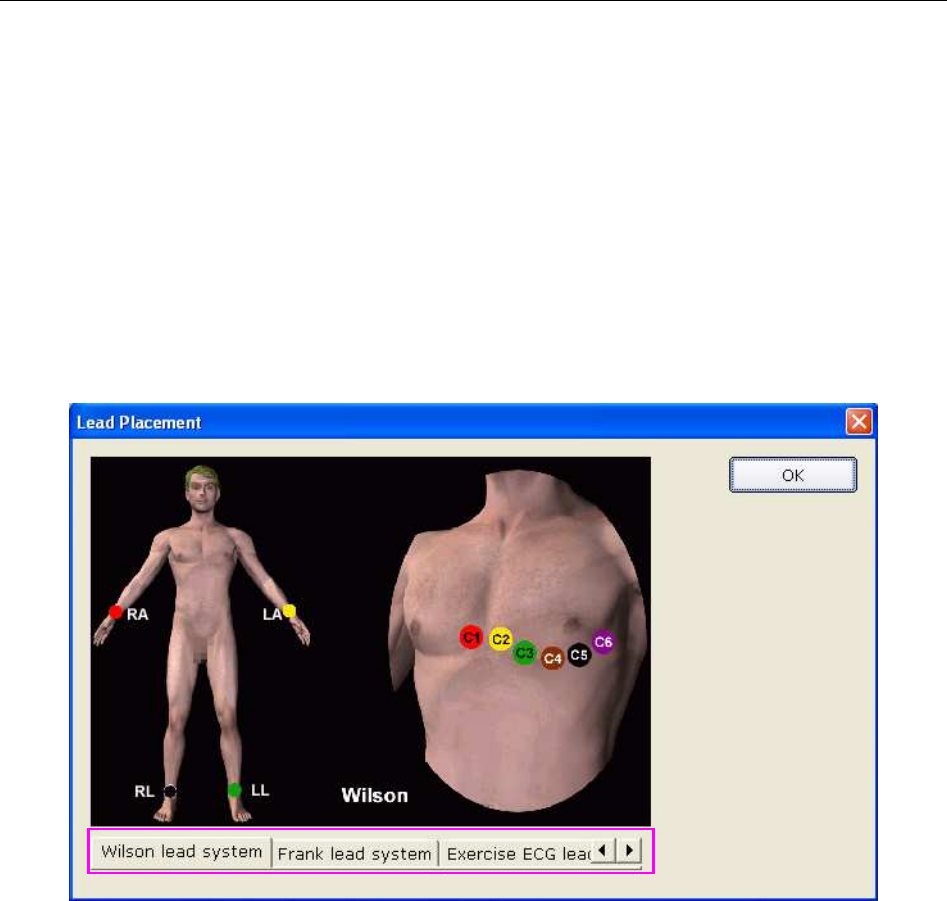
6.1 Viewing Lead Placement Information
1. Click on the Lead Placement button on the main screen to display the Lead Placement
window.
2. Click on Wilson lead system, Frank lead system or Exercise ECG lead system to view the
lead placement information in the corresponding system.
SE-1010 PC ECG User Manual Operation Instructions for Resting ECG
- 44 -
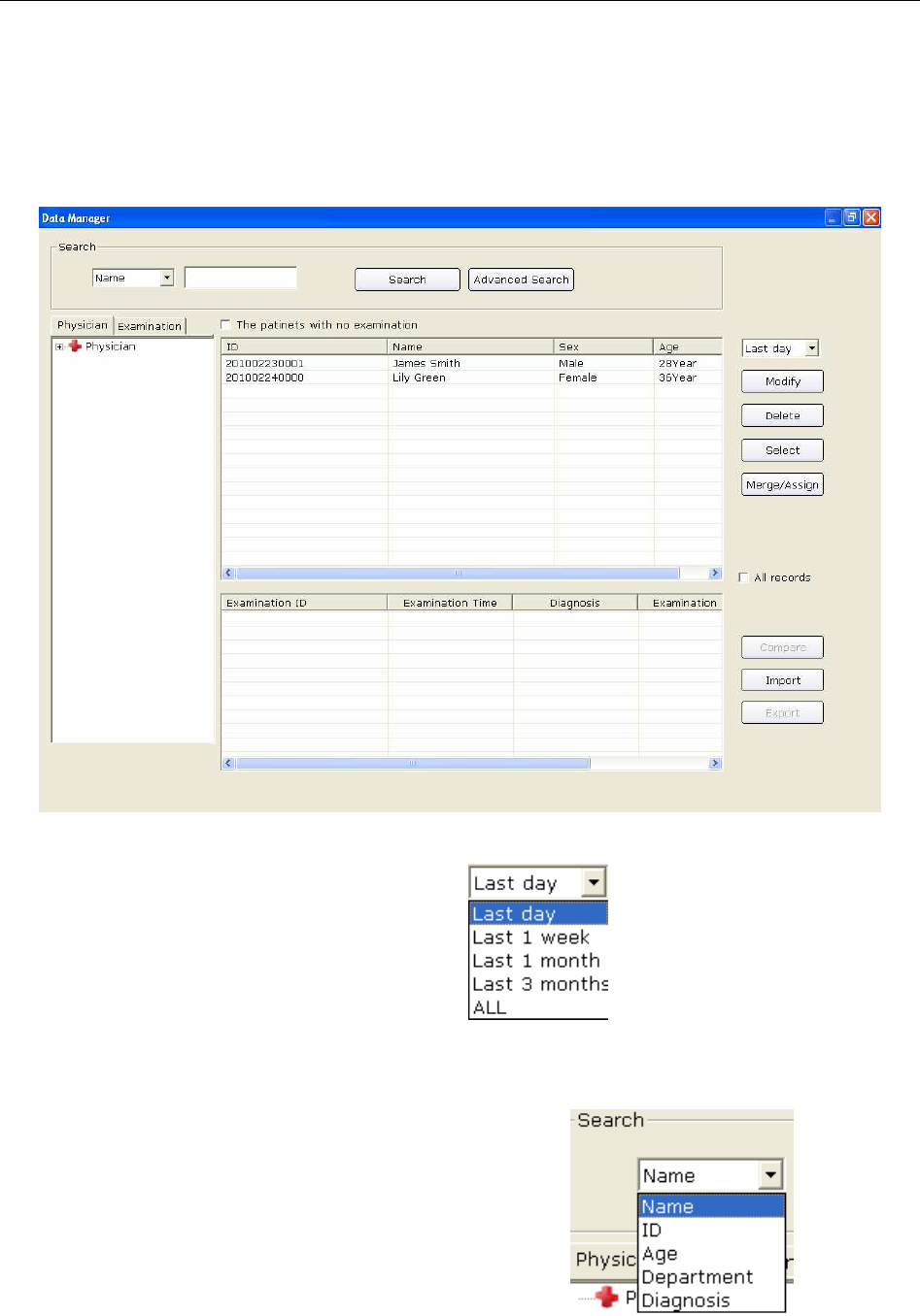
6.2 Selecting a Patient Record to Start a New Test
Click on the Data Manager button on the main screen (Figure 6-1) to open the Data Manager
screen (Figure 6-3).
Figure 6-3 Data Manager Screen
1. Select a search item in the pull-down list on the Data Manager screen.
Then all the patient records which meet the search condition are listed in the patient
information list.
2. Or, select a search item in the pull-down list , enter the
corresponding information in the right textbox, and then click on the Search button. All the
patient records which meet the conditions will be displayed in the patient information list.
SE-1010 PC ECG User Manual Operation Instructions for Resting ECG
- 45 -
3. Or, click on Advanced Search to display the Search Condition window. Enter the search
conditions, and click on the Search button, and all the patient records which meet the
conditions will be displayed in the patient information list.
4. Click on the patient record in the patient information list and click on the Select button to
open the Patient Information window. Or, double-click on the patient record in the patient
information list to open the Patient Information window.
Figure 6-4 Patient Information Window
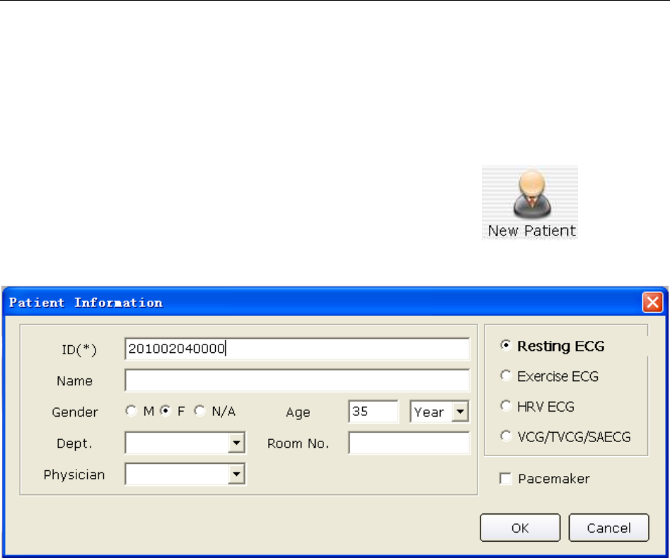
SE-1010 PC ECG User Manual Operation Instructions for Resting ECG
- 46 -
6.3 Entering New Patient Information
6.3.1 Entering New Patient Information Manually
If the patient is a new one, you can click on the New Patient button on the main
screen (Figure 6-1) to display the Patient Information window.
Then you need to input the patient’s related information.
1. Enter basic information, such as patient ID, name, sex and age.
User-defined 1 and User-defined 2: You can input other related information such as patients’
medical records.
User-defined 1 and User-defined 2 can be set in the Basic Information window (Figure 9-1).
Before setting them, the two items in the Patient Information window are unavailable. For
details, please refer to Section 9.1.1, “Setting Basic Information”.
NOTE: In the Patient information window, patient ID is a must. You can use the
number generated by the system or input a number manually. Patient ID can
be a random character string excluding ‘/’, ‘\’, ‘:’, ‘*’, ‘?’, ‘<’, ‘>’ and ‘|’.
2. Enter additional information, such as BP, height, weight, medication and race.
NOTE: You can select the additional information items in the Print Setting window,
and these additional information items will be displayed in the Patient
Information window after setting printer.
For details, please refer to Section 9.4.1, “Choosing Patient Information to be Printed”.
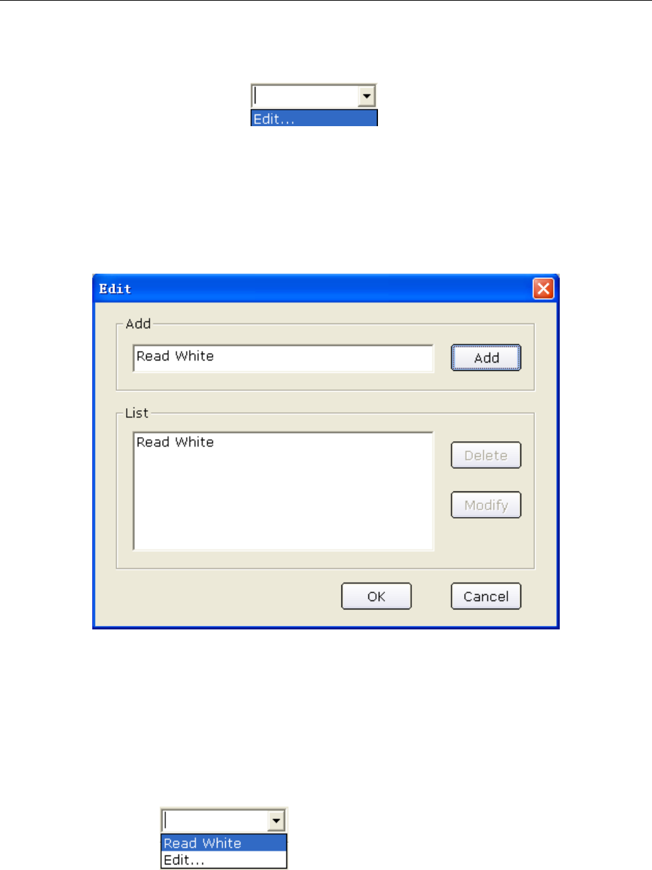
SE-1010 PC ECG User Manual Operation Instructions for Resting ECG
- 47 -
3. Enter information of doctor and department
1) Enter information of physician, technician or Req. physician
Click on the pull-down list , and then click on the Edit button to
display the Edit window.
Enter the doctor name in the textbox, and then click on the Add button. The doctor name
will be displayed in List. Meanwhile, you can also directly enter the doctor name in
textbox of Physician item, and then click on the OK button in the Patient Information
window.
Click on one name in List, and then you can delete or modify the name:
a) Click on the Delete button, and then click the OK button to delete the name from the
list.
b) Click on the Modify button, enter a new name in textbox to modify the name, and
then click on the OK button.
Click on the OK button to confirm and exit the Edit window, and then click on the
pull-down list , you can select the doctor name you enter.
NOTE: Take the same steps above for entering information of technician or
Req.physician.
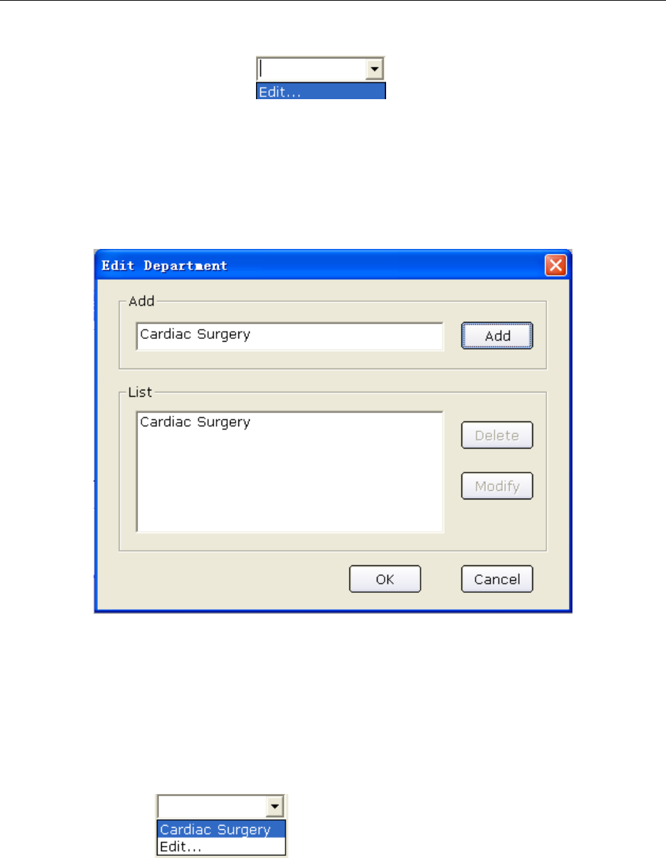
SE-1010 PC ECG User Manual Operation Instructions for Resting ECG
- 48 -
2) Enter information of department
Click on the pull-down list , and then click on the Edit button to
display the Edit Department window.
Enter the department name in the textbox, and then click on the Add button. The doctor
name will be displayed in List. Meanwhile, you can also enter the department name in the
textbox of Dept. item, and then click on the OK button in the Patient Information
window.
Click on one department name in List, and then you can delete or modify the name:
♦ Click on the Delete button, and then click the OK button to delete the department
name from the list.
♦ Click on the Modify button, enter a new name in the textbox to modify the
department name, and then click on the OK button.
Click on the OK button to confirm and exit the Edit window, and then click on the
pull-down list , you can select the doctor name you enter.
NOTE: You can select Physician, Technician or Req.physician in the Print
Setting window. Before setting them, these items in the Patient
Information window are unavailable. For details, please refer to Section
9.4.1, “Choosing Patient Information to be Printed”.

SE-1010 PC ECG User Manual Operation Instructions for Resting ECG
- 49 -
4. Confirm pacemaker information
If you select Pacemaker in the Print Setting window, Pacemaker appears in the Patient
Information window. Select Pacemaker to detect very small pacemaker pulses. However,
when pacemaker pulse enhancer is on, the system is very sensitive, and should not be close to
equipment emitting high frequency radiation. High frequency radiation can interfere with
pacemaker pulse detection and normal ECG acquisition.
NOTE: Pacemaker is recommended to be deselected unless it is known that the
majority of the electrocardiograph usage will be on patients with
pacemakers.
5. Select risk indicators and symptoms (for Exercise ECG), such as cigarette, diabetes,
congenital heart disease, hypertension, hyperlipemia and family medical history.
NOTE: You can select risk indicators and symptoms only in Exercise ECG mode.
6.3.2 Entering Patient Information by Using a Bar Code Reader
Operation procedures are as follows:
1. Configure the bar code
For more detailed information about configuring the bar code, please refer to Section 9.3.5.2,
“Setting Barcode”.
NOTE: If the two-dimensional bar code reader is used, you should install Symbol
COM Port Emulation Drive manually. For details, please refer to SE-1010 PC
ECG Installation Guide.
2. Connect the bar code reader to the PC.
3. Log into the PC ECG software.
4. When the main screen or the Patient Information window is displayed, scan the patient’s
bar code with the bar code reader, and then the patient information will appear in the
corresponding boxes of the Patient Information window.
NOTE:
1. Only bar code readers recommended by the manufacturer can be used.
2. Only the basic information of the patient can be scanned by the bar code
reader.
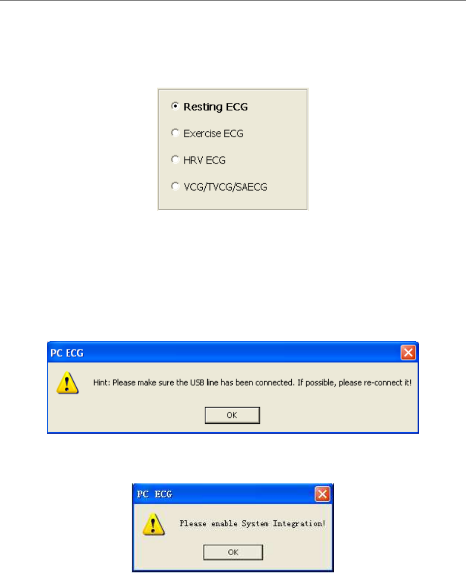
SE-1010 PC ECG User Manual Operation Instructions for Resting ECG
- 50 -
6.4 Selecting Sampling Type
You can select a sampling type in the Patient information window.
6.5 Sampling Resting ECG
After inputting the patient information, click on the OK button in the Patient information
window to open the ECG sampling screen.
Before sampling, if you do not connect the PC to the ECG sampling box, the following hint will
pop up.
If the system is invocated by Smart ECG Net, but the system integration is not activated, the
following hint will pop up.
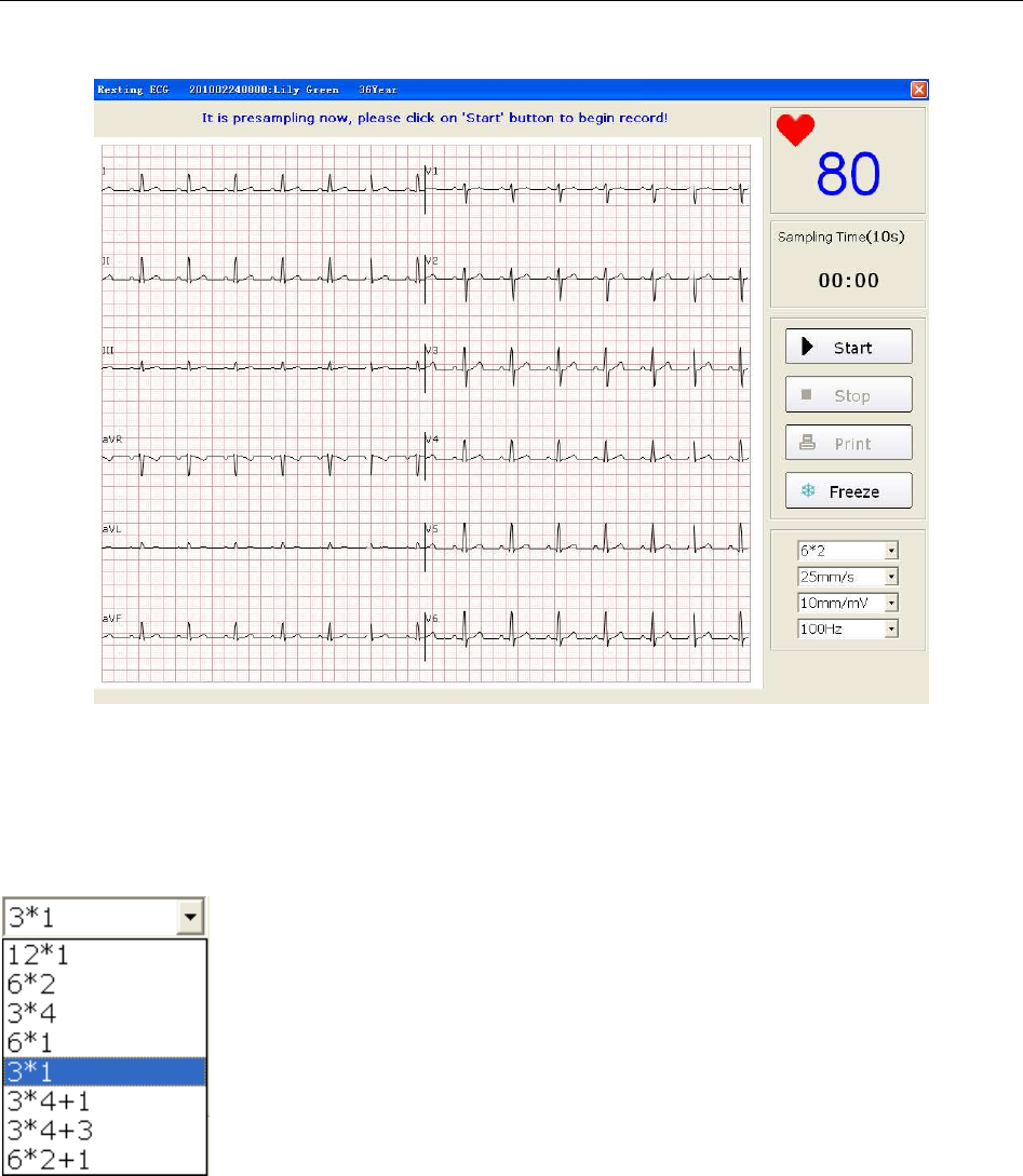
SE-1010 PC ECG User Manual Operation Instructions for Resting ECG
- 51 -
The system begins to pre-sample ECG.
Figure 6-5 Pre-Sampling Screen
6.5.1 Specifying Display Mode
There are eight display modes including 12*1, 6*2, 3*4, 6*1, 3*1, 3*4+1, 3*4+3 and 6*2+1.
When the display mode is set to 12*1, 12-channel ECG waves are displayed on one screen
simultaneously.
When the display mode is set to 6*2, 12-channel ECG waves are displayed in 2 groups of 6 on
one screen.
When the display mode is set to 3*4, 12-channel ECG waves are displayed in 4 groups of 3 on
one screen.
When the display mode is set to 6*1, 6-channel ECG waves are displayed on one screen.
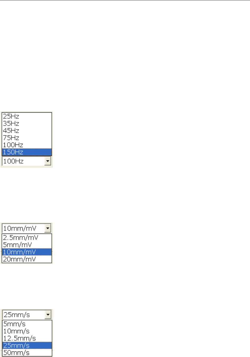
SE-1010 PC ECG User Manual Operation Instructions for Resting ECG
- 52 -
When the display mode is set to 3*1, 3-channel ECG waves are displayed on one screen
simultaneously.
When the display mode is set to 3*4+1, 12-channel ECG waves are displayed in 4 groups of 3
and one rhythm lead on one screen.
When the display mode is set to 3*4+3, 12-channel ECG waves are displayed in 4 groups of 3
and three rhythm leads on one screen.
When the display mode is set to 6*2+1, 12-channel ECG waves are displayed in 2 groups of 6
and one rhythm lead on one screen.
6.5.2 Specifying Lowpass Filter
Lowpass Filter restricts the bandwidth of input signals. The cutoff frequency can be set to 25Hz,
35Hz, 45Hz, 75Hz, 100Hz, or 150Hz. The input signals whose frequency is higher than the set
cutoff frequency will be attenuated.
6.5.3 Specifying Gain
You can set the indicated length of 1mV ECG on the paper.
You can set the gain to 2.5mm/mV, 5mm/mV, 10mm/mV or 20mm/mV.
6.5.4 Specifying Speed
You can set the paper speed to 5mm/s, 10mm/s, 12.5mm/s, 25mm/s or 50mm/s.
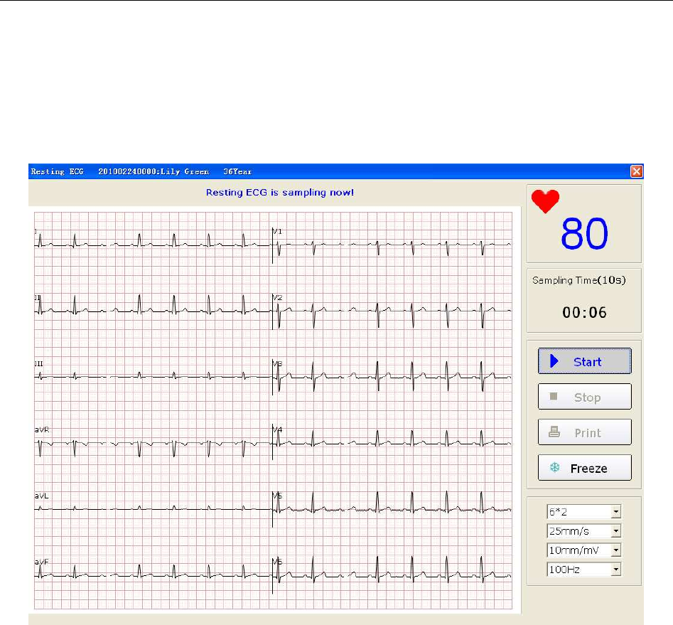
SE-1010 PC ECG User Manual Operation Instructions for Resting ECG
- 53 -
6.5.5 Recording ECG Data
When the pre-sample ECG waves are steady, you can click on the Start button to save the
sampled ECG data to the designated directory. For details, please refer Section 9.1.4, “Specifying
the Storage Path of the ECG Data”.
Figure 6-6 ECG Sampling Screen
NOTE: After you click on the Start button, the system will save the sampled ECG data. If
you don’t click on the Start button, the system won’t save the sampled ECG data.
6.5.6 Freezing and Previewing ECG
Click on the Freeze button on the ECG sampling screen (Figure 6-6), the system will display the
Wave review window. The system can review a 3-minute (at least) waveform (counted from
before clicking on the Freeze button for 3 minutes). You can review the waveform by dragging
the scrollbar and you can print the current waveform by clicking on the Print button.
NOTE:Printing ECG reports in the Wave review window are only available for Resting
ECG and Exercise ECG.
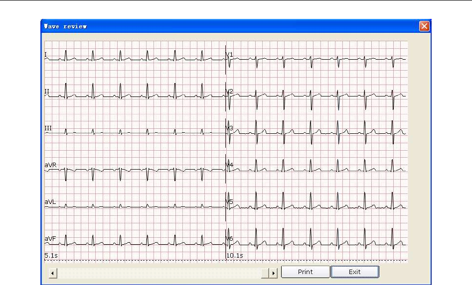
SE-1010 PC ECG User Manual Operation Instructions for Resting ECG
- 54 -
Figure 6-7 Wave Review Window
Click on Exit to return to the ECG sampling screen.
NOTE: The display modes in the Wave review window are the modes you select on the
ECG sampling screen. 3*1 and 6*1 display modes are displayed in 3*4 and 6*2
modes.
6.5.7 Stopping Sampling Data
After clicking on the Start button, there are two ways to stop sampling data.
1. The system will stop sampling ECG data and display the ECG analysis screen automatically
after the ECG sampling time is over. For details, please refer to Section 9.2.2, “Setting
Sampling Time”.
2. Before the ECG sampling time is over, you can click on the Stop button to stop sampling
data and the ECG analysis screen will pop up automatically.

SE-1010 PC ECG User Manual Operation Instructions for Resting ECG
- 55 -
6.5.8 Printing ECG Waves
Click on the Print button on the ECG sampling screen to print the ECG waves on the ECG
sampling screen.
NOTE:
1. You can set the printer type on the Printer and Faxes screen. For details, please
refer to Section 6.6.10, “Printing ECG Reports”.
2. The report can be printed in white- black or color. The report color is defined by
setting the printer type and can be observed on the preview screen. For details,
please refer to Section 9.4.4, “Print Setup”.
6.6 Analyzing ECG Data
You can open the ECG analysis screen in one of the following three ways:
1. Click on the Start button, and then the system will stop sampling ECG and display the ECG
analysis screen automatically after the ECG sampling time is over.
2. Or, click on the Stop button to stop sampling after clicking on the Start button, and the
system will display the ECG analysis screen automatically.
3. Or, double-click on an examination record in the examination record list on the Data
Manager screen (Figure 6-3) to open the ECG analysis screen.
When Resting ECG is selected as the sampling type, the ECG analysis screens include Normal
ECG, QT Dispersion (QTD), Frequency ECG (FCG) and High Frequency ECG (HF ECG).
When HRV ECG is selected as the sampling type, the ECG analysis screens include Heart Rate
Variability (HRV) and Heart Rate Turbulence (HRT).
When VCG/TVCG/SAECG is selected as the sampling type, the ECG analysis screens include
Vector ECG (VCG), Time Vector ECG (TVCG) and Signal Averaged ECG (SAECG).
6.6.1 Analyzing Normal ECG
Click on the Normal Analysis button to open the normal ECG analysis screen. There are four
tabs: Waveform, Average Template, Detail information and Rhythm Wave.
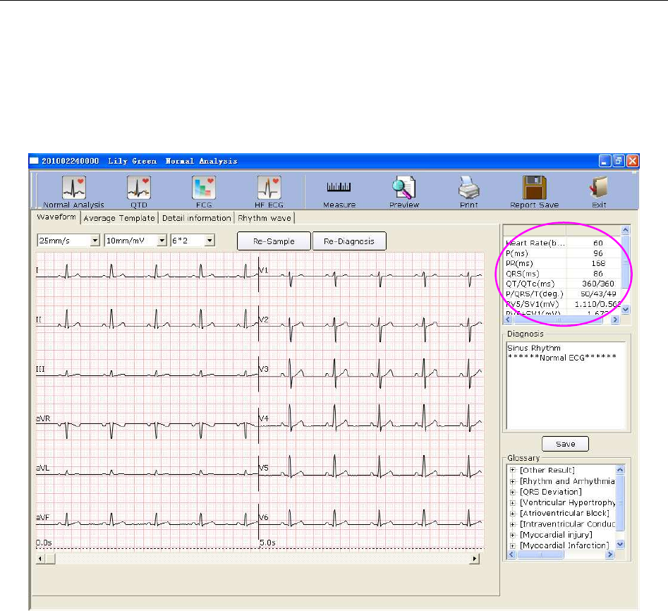
SE-1010 PC ECG User Manual Operation Instructions for Resting ECG
- 56 -
6.6.1.1 Viewing the Waveform
Click on the Waveform tab on the normal ECG analysis screen to open the Waveform window
(Figure 6-8).
Figure 6-8 Normal ECG - Waveform Window
You can choose a speed, a gain and a display mode for the displayed waves.
Click on the Measure button in the Waveform window (Figure 6-8). Click on one point on the
wave, and then drag the mouse to another point. The distance, amplitude difference and heart rate
between the two points will be displayed.
NOTE:
1. You can measure the distance between any two points more than once after running
the ruler. The last measure track and data will be displayed after the measurement.
2. Only ECG waves can be measured.
Click on Re-Sample, and then the system can re-sample ECG data.
Click on Re-Diagnosis, and then the system can re-diagnose the 10s ECG data on the screen
automatically.
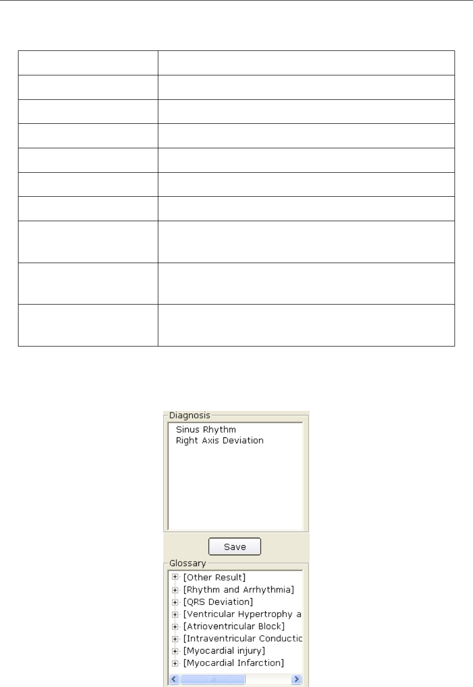
SE-1010 PC ECG User Manual Operation Instructions for Resting ECG
- 57 -
The common parameters are displayed in the circle in Figure 6-8. These parameters are as
follows.
Designation Description
Heart Rate Heart Rate
P Duration P-wave duration of the current lead
PR Dur. P-R interval of the current lead
QRS Dur. QRS complex duration of the current lead
QT/QTc Q-T interval of the current lead/Normalized QT interval
P/QRS/T Dominant direction of the average integrated ECG vectors
RV5/SV1 The amplitude of R wave of V5 lead/the amplitude of S
wave of V1 lead
RV5+SV1 The amplitude of R wave of V5 lead plus the amplitude of
S wave of V1 lead
RV6/SV2 The amplitude of R wave of V6 lead/the amplitude of S
wave of V2 lead
Double-click on a parameter, and then you can modify it. Then click on the Save button to save
the modifications.
To Edit Diagnosis Result in the Waveform Window
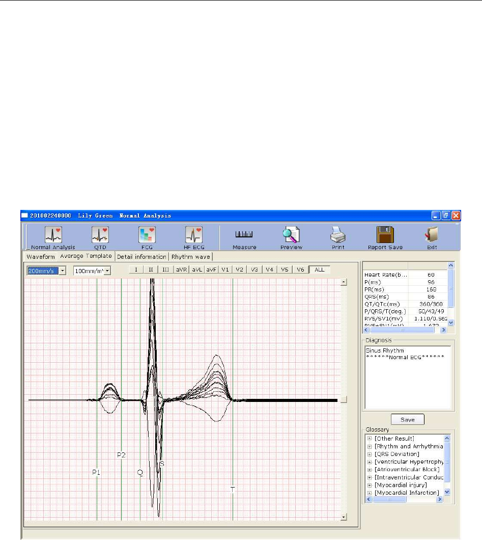
SE-1010 PC ECG User Manual Operation Instructions for Resting ECG
- 58 -
1. Enter your own opinions in the Diagnosis textbox, and then click on the Save button.
2. Or, double-click on the necessary results required to be added in the Glossary textbox, the
selected results will be displayed in the Diagnosis textbox, and then click on the Save button.
If the Integration function is activated, the data can be uploaded to Smart ECG Net system after
you click on the Save button.
6.6.1.2 About the Average Template Window
Click on the Average Template tab on the normal ECG analysis screen to open the Average
Template window (Figure 6-9). You can analyze average templates in this window.
Figure 6-9 Normal ECG - Average Template Window
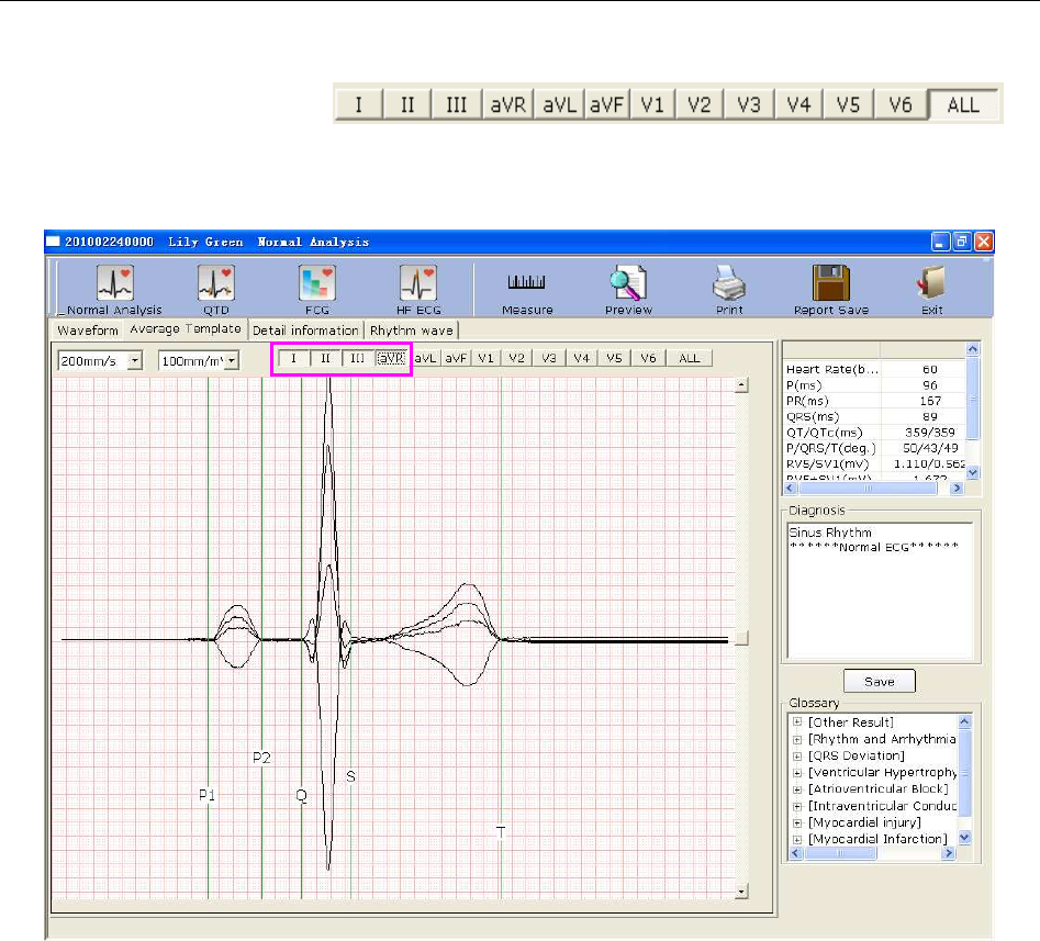
SE-1010 PC ECG User Manual Operation Instructions for Resting ECG
- 59 -
To Edit Waveform on the Analysis Screen
You can press a lead button in to
display magnified average templates of this lead. When you press more than one lead button,
magnified average templates of these leads will be overlapped with the same central axis.
When you press ALL, magnified average templates of all leads will be overlapped with the same
central axis.
You can set the speed and the gain of average templates.
You can drag marker lines of P1, P2, Q, S and T on average templates.
P1 is the start point of P wave, P2 is the end point of P wave, Q marks the position of Q point, S
marks the position of S point, and T is the end point of T wave. You can move these lines by
dragging on the mouse and the mouse will turn to a hand pointer when it is put on these marks.
You can also use the arrows key on the keyboard to move these marks, and the corresponding
parameter values will change.
To Edit Diagnosis Result in the Average Template Window
For details, please refer to Section 6.6.1.1, “Viewing the Waveform”.
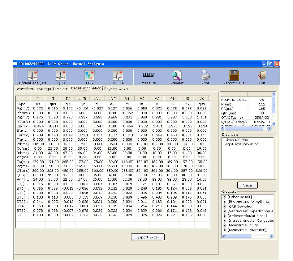
SE-1010 PC ECG User Manual Operation Instructions for Resting ECG
- 60 -
6.6.1.3 About the Detail Information Window
Click on the Detail information tab on the normal ECG analysis screen to open the Detail
information window. This window displays lead parameter values as Figure 6-10 shows.
Figure 6-10 Normal ECG - Detail Information Window
Click on the Export Excel button to export an Excel file.
To Edit Diagnosis Result in the Detail Information Window
For details, please refer to Section 6.6.1.1, “Viewing the Waveform”.
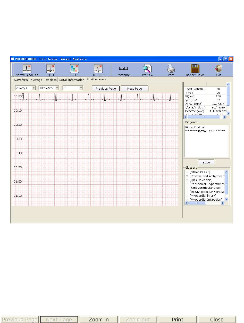
SE-1010 PC ECG User Manual Operation Instructions for Resting ECG
- 61 -
6.6.1.4 About the Rhythm Wave Window
Click on the Rhythm Wave tab on the normal ECG analysis screen to open the Rhythm wave
window. This window displays rhythm wave as Figure 6-11 shows.
Figure 6-11 Normal ECG - Rhythm Wave Window
You can set the gain, the speed and the lead of the displayed ECG waves.
You can click on Previous Page or Next Page to display the waves of the previous or next page.
Click on one point on the wave, and then drag the mouse to another point. Then click on Print to
print the selected wave field.
6.6.1.5 Previewing Normal ECG
Click on the Preview button to display the normal ECG preview screen.
is
the toolbar on the normal ECG preview screen.
1. Click on Previous Page/Next Page to switch to the previous/next preview page.
2. Click on Zoom In/ Zoom Out to magnify/minify the preview page.
3. Click on Print to print the report.
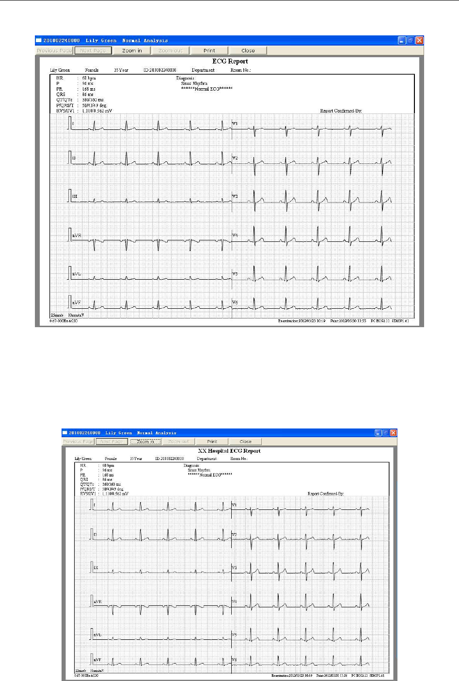
SE-1010 PC ECG User Manual Operation Instructions for Resting ECG
- 62 -
4. Click on Close to close the normal ECG preview screen and return to the previous screen.
Figure 6-12 ECG Wave
NOTE: The report title is in one line by default, you can also change the line to two lines.
Find the text named PCECG.ini in the installation path, modify LineofTitle=0 to
LineofTitle=1, and then save the text to change the line to two lines.
Effect pictures of report title are as shown below:
Report Title in One Line
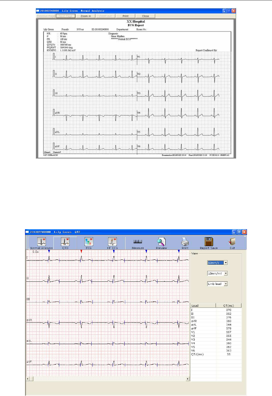
SE-1010 PC ECG User Manual Operation Instructions for Resting ECG
- 63 -
Report Title in Two Lines
6.6.2 Analyzing QT Dispersion
Click on the QTD button to open the QT Dispersion screen.
QT Dispersion: The difference between the largest QT interval and the shortest QT interval based
on the synchronous 12-lead surface ECG. The QT interval is a measurement of the time
difference between the start of the Q wave and the end of the T wave.
Figure 6-13 QT Dispersion screen
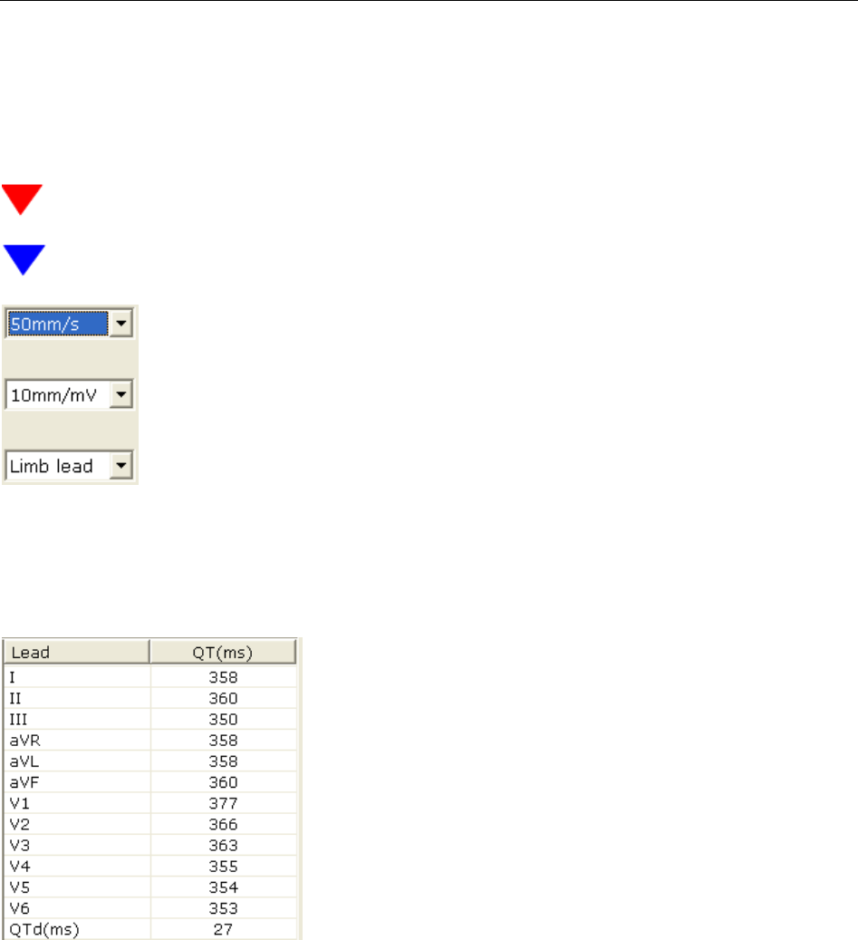
SE-1010 PC ECG User Manual Operation Instructions for Resting ECG
- 64 -
6.6.2.1 Editing Waveform on the QT Dispersion Screen
There are red and blue triangle icons on top of the displayed ECG waves. You can click on the
triangle icon to change the color.
represents the current chosen R wave
represents the position of R wave
You can set the speed and the gain of the displayed ECG waves. The lead
number and the lead type of the displayed ECG waves can also be chosen.
6.6.2.2 About QT Value
QT values of 12 leads and QT dispersion (QTd) are displayed
as the left figure shows.
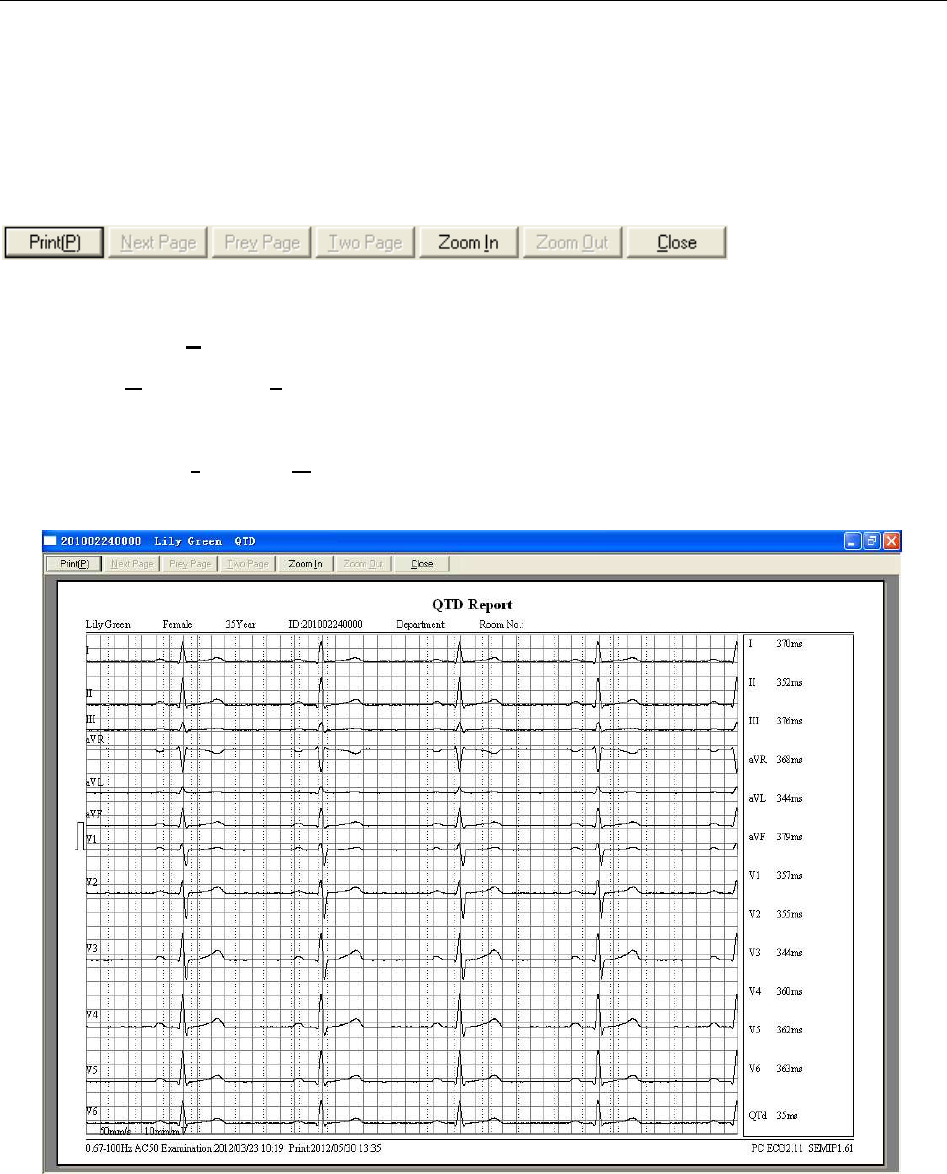
SE-1010 PC ECG User Manual Operation Instructions for Resting ECG
- 65 -
6.6.2.3 Previewing QT Dispersion
Click on the Preview button on the QT Dispersion screen to open the QT Dispersion preview
screen.
is the toolbar on the
QT Dispersion preview screen.
1. Click on Print(P) to print the report.
2. Click on Next Page/Prev Page to switch to the previous/next preview page.
3. Click on Two Page to preview two pages on one screen simultaneously.
4. Click on Zoom In/ Zoom Out to magnify/minify the preview page.
5. Click on Close to close the preview screen and return to the previous screen.
Figure 6-14 QT Dispersion Preview Screen
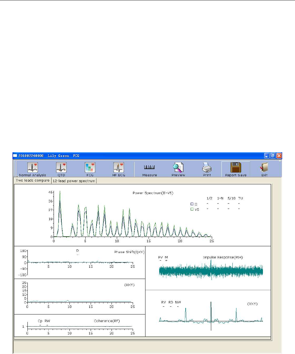
SE-1010 PC ECG User Manual Operation Instructions for Resting ECG
- 66 -
6.6.3 Analyzing Frequency ECG
Click on the FCG button to open the Frequency ECG screen.
Frequency ECG displays characteristic waves of ECG signal spectrum.
There are two tabs on the Frequency ECG screen: Two leads compare and 12-lead power
spectrum.
6.6.3.1 About Two-lead Comparison Window
The two-lead comparison window displays the power spectrum, phase shift, amplitude shift,
coherence, impulse response and correlation functions of ECG waves, as Figure 6-15 shows.
Figure 6-15 Frequency ECG - Two-lead Comparison Window

SE-1010 PC ECG User Manual Operation Instructions for Resting ECG
- 67 -
Every parameter of Frequency ECG is shown in the following table.
Designation Definition
Power
Spectrum
1/2 If the first peak value is lower than 90% of the second peak
value, it is positive (‘+’). Otherwise it is minus (‘-’).
1-N
The first peak is too low or disappears. (The frequency value
of the first peak’s position * 60 = heart rate. For example, if
the frequency value of the first peak’s position is 1.2, the
heart rate is 72.)
5/10 If the peak value of any peak behind the fifth peak is higher
than the first peak value, it is positive. Otherwise it is minus.
TU If the distances between peak values are not equal, it is
positive. Otherwise it is minus.
Phase Shift D If the phase shift in the range of 6~18Hz exceeds 90 degrees,
it is positive. Otherwise it is minus.
Coherence
Cp
If the coherence value of the fundamental (the position of the
first peak in power spectrum) is less than 0.8, it is positive.
Otherwise it is minus.
RW
If there are four twists and turns with peak-to-valley
interval >0.5r or five twists and turns with peak-to-valley
interval >0.1 in the range of 10~20Hz, it is positive.
Otherwise it is minus.
Impulse
Response
PV
If the main peak in the middle upends, the downward peak
value is higher than the upward peak value, it is positive.
Otherwise
it
is
minus.
M If there is a peak around the main peak higher than 60% of
the main peak, it is positive. Otherwise it is minus.
Correlation
Function
(VXY)
RV If the main peak in the middle upends, it is positive.
Otherwise it is minus.
RD If the main peak in the middle deviates from the origin and
the baseline, it is positive. Otherwise it is minus.
NW The main peak is like the letter ‘N’.
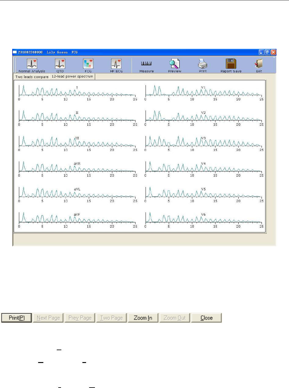
SE-1010 PC ECG User Manual Operation Instructions for Resting ECG
- 68 -
6.6.3.2 About 12-lead Power Spectrum Window
The 12-lead power spectrum window displays the power spectrum of 12-lead ECG waves.
Figure 6-16 Frequency ECG - 12-lead Power Spectrum Window
6.6.3.3 Previewing Frequency ECG
Click on the Preview button to open the Frequency ECG preview screen.
is the toolbar on the
Frequency ECG preview screen.
1. Click on Print(P) to print the report.
2. Click on Next Page/Prev Page to switch to the previous/next preview page.
3. Click on Two Page to preview two pages on one screen simultaneously.
4. Click on Zoom In/ Zoom Out to magnify/minify the preview page.
5. Click on Close to close the preview screen and return to the previous screen.
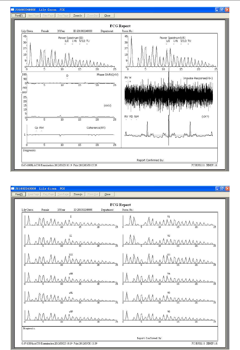
SE-1010 PC ECG User Manual Operation Instructions for Resting ECG
- 69 -
Figure 6-17 Two-lead Comparison Report
Figure 6-18 12-lead Power Spectrum Report
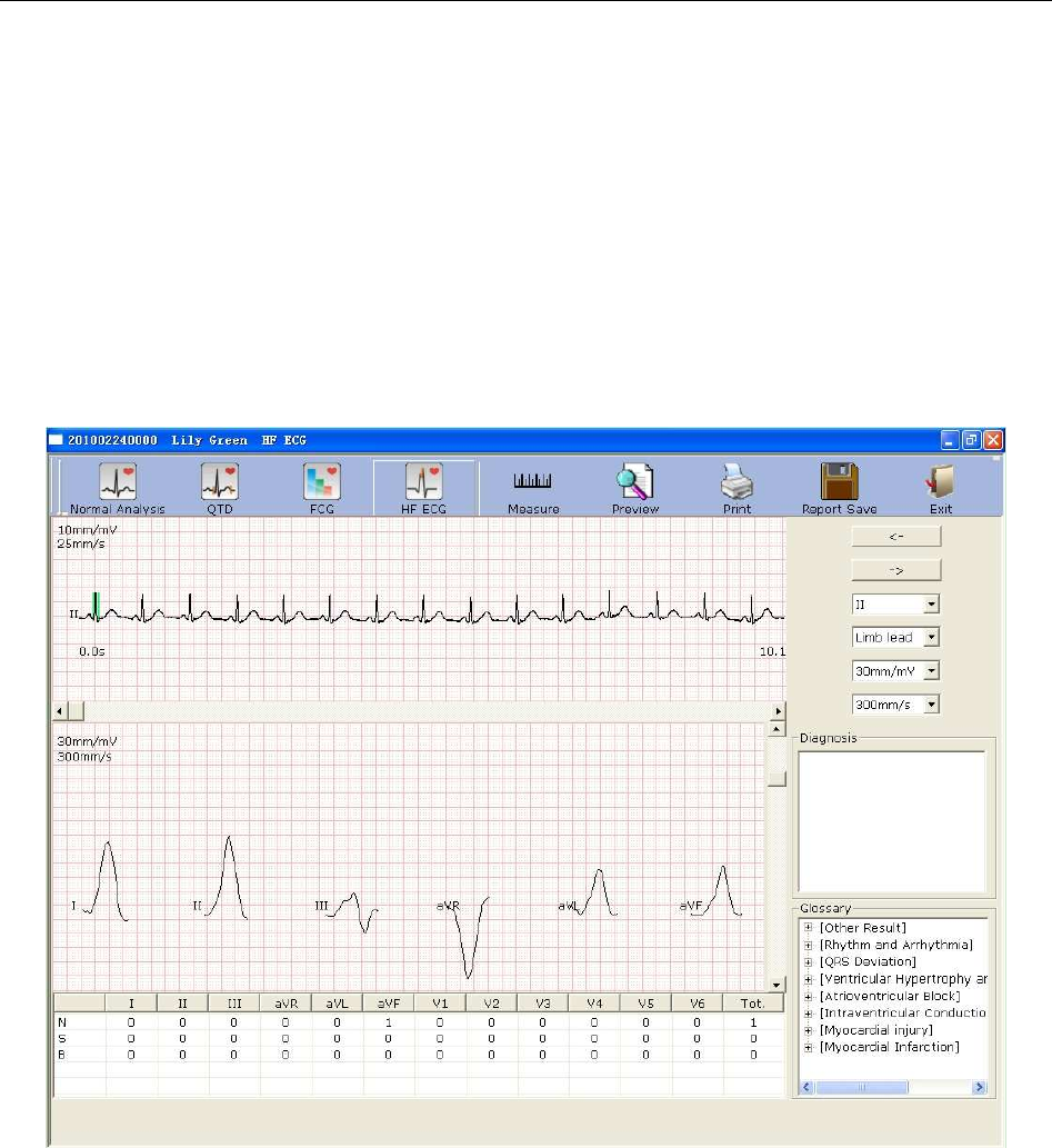
SE-1010 PC ECG User Manual Operation Instructions for Resting ECG
- 70 -
6.6.4 Analyzing High Frequency ECG
In a conventional electrocardiogram, only these ECG signals, of which the amplitude is in the
millivolt range and the frequency is less than 100 Hz, are visible. Those ECG signals, of which
the amplitude is in the microvolt range and the frequency is between 150Hz and 250Hz, are
invisible. If these invisible high frequency components are abnormal, it is the indication of
myocardial ischemia or myocardial infarction.
HF ECG is to detect high frequency components of QRS such as notches, slurs and beadings.
Click on the HF ECG button to open the HF ECG analysis screen.
Figure 6-19 HF ECG Analysis Screen
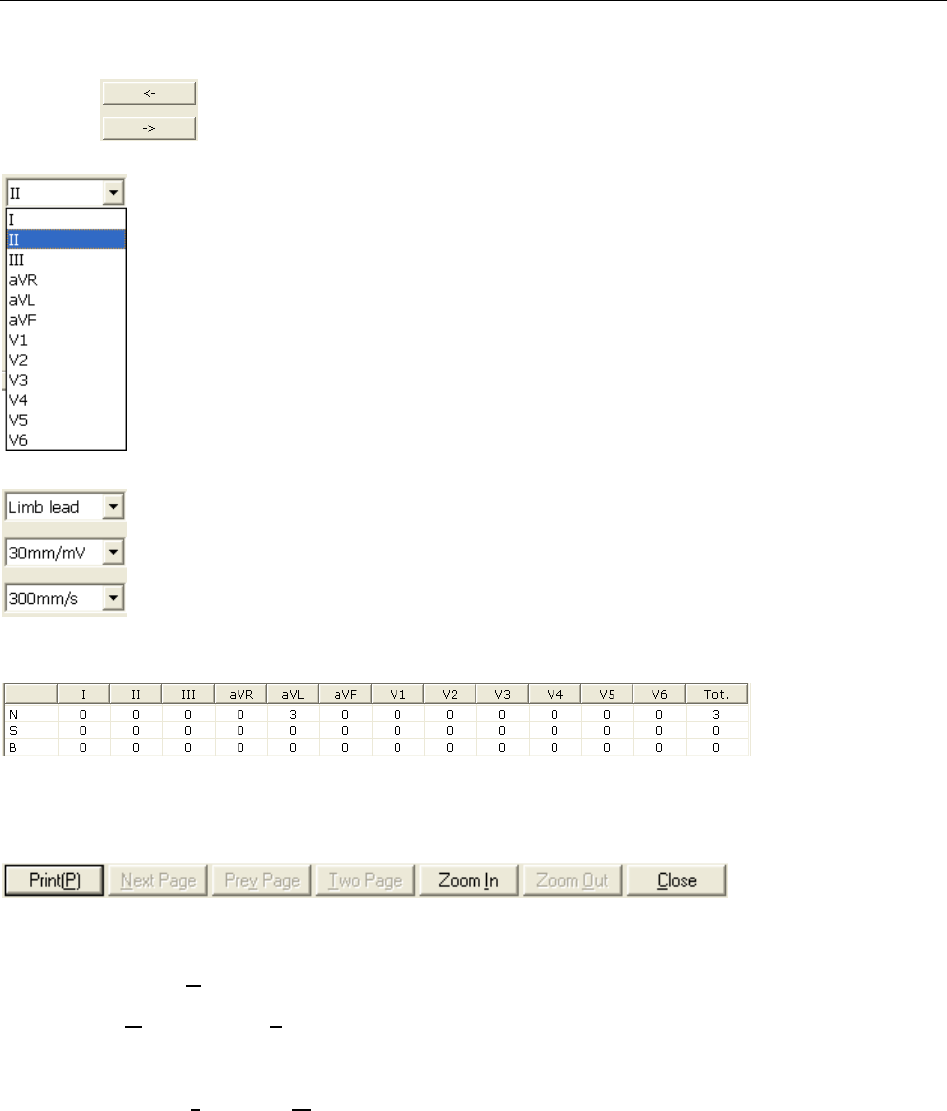
SE-1010 PC ECG User Manual Operation Instructions for Resting ECG
- 71 -
The ECG wave between the two green lines is the present one.
Click on to select another QRS wave. Select the present lead in the pull-down list
.
You can choose the lead group, the gain and the speed of the waves displayed in the
bottom part of the HF ECG analysis screen.
is the statistic data
of beadings, notches and slurs. You can change a value by double-clicking on the value.
Click on the Preview button to open the HF ECG preview screen.
is the toolbar on the
HF ECG preview screen.
1. Click on Print(P) to print the report.
2. Click on Next Page/Prev Page to switch to the previous/next preview page.
3. Click on Two Page to preview two pages on one screen simultaneously.
4. Click on Zoom In/ Zoom Out to magnify/minify the preview page.
5. Click on Close to close the preview screen and return to the previous screen.
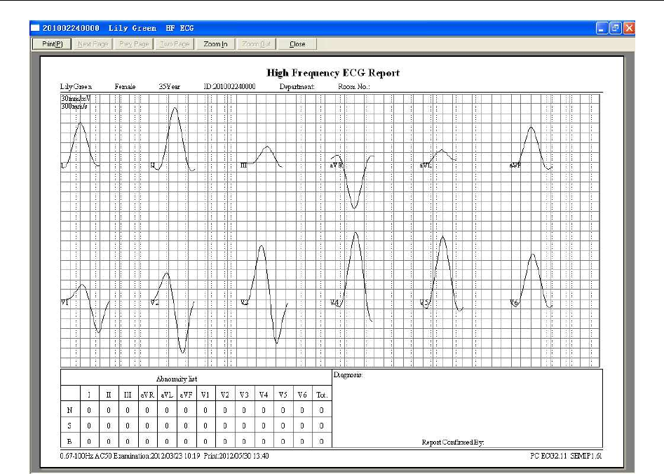
SE-1010 PC ECG User Manual Operation Instructions for Resting ECG
- 72 -
Figure 6-20 HF ECG Report
6.6.5 Analyzing HRV
Click on HRV to display the HRV ECG analysis screen. The HRV ECG analysis screen includes
two tabs: Auto diagnosis result and Waveform.
NOTE:
1. The HRV sampling time can be set in the Sample Setting window.
2. The HRV analysis lead can be selected in the Sample Setting window.
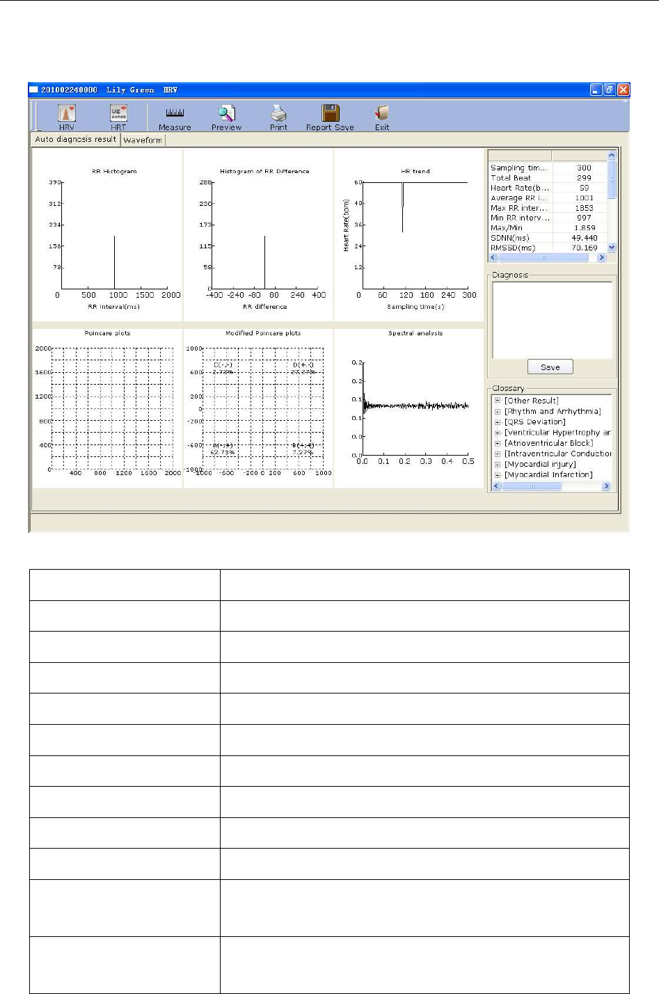
SE-1010 PC ECG User Manual Operation Instructions for Resting ECG
- 73 -
6.6.5.1 Editing the HRV Data on the Analysis Screen
Figure 6-21 Analysis Screen of HRV
Designation Definition
Sampling time Set sampling time
Total Beat Total beat number during the measuring course
Heart Rate Heart rate
Average RR interval Average RR interval
Max RR interval Maximum RR interval
Min RR interval Minimum RR interval
Max/Min Ratio of Maximum RR interval to Minimum RR interval
SDNN Standard Deviation of Normal to Normal Intervals
RMSSD Root Mean Square Successive Difference
NN50
(the total beat number)
The number of duration difference that is more than 50ms
between the adjacent NN durations.
PNN50
(unit:
per centum)
NN50 divide the total NN number
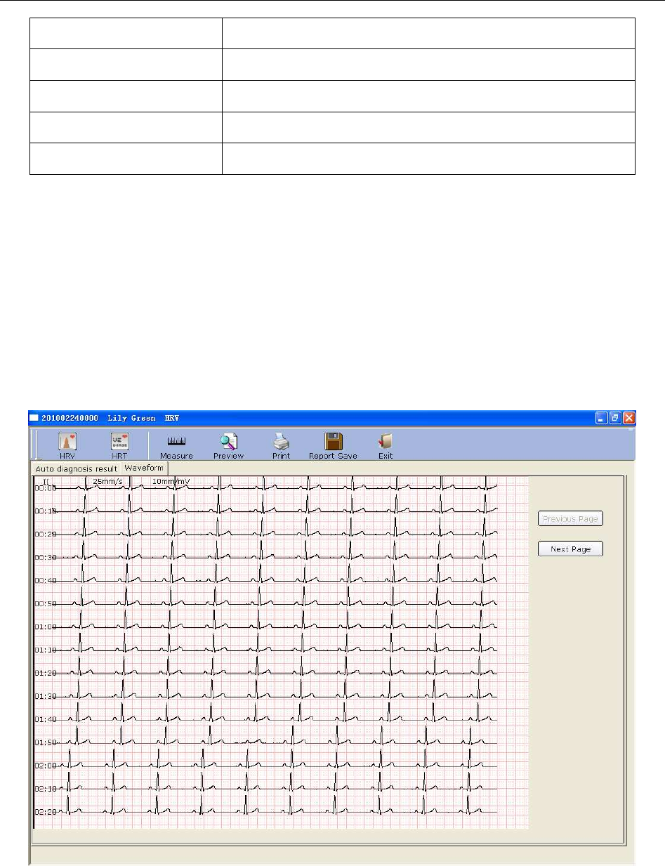
SE-1010 PC ECG User Manual Operation Instructions for Resting ECG
- 74 -
LF Low Frequency
HF High Frequency
LF/HF Ratio of low frequency to high frequency
LF (norm) Standard LF power
HF (norm) Standard HF power
H- Doctor Diagnosis Field
1. Enter your own opinions in the Auto diagnosis textbox, and then click on the Save button.
2. Or, double-click on the necessary results required to be added in the Glossary textbox, the
selected results will be displayed in the Auto Diagnosis textbox, and then click on the Save
button.
6.6.5.2 Editing the HRV Waveform in the Waveform Window
Figure 6-22 Waveform Window of HRV
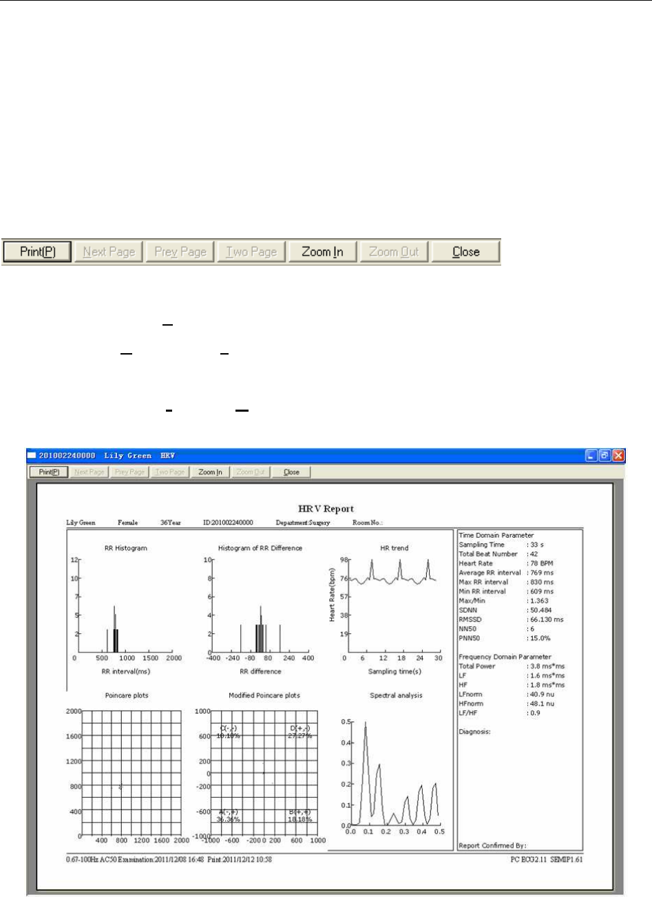
SE-1010 PC ECG User Manual Operation Instructions for Resting ECG
- 75 -
HRV waveform is displayed in the Waveform window (Figure 6-22).
1. You can drag the mouse in the window to choose the wave field to be printed. Then click on
the Print button to print the selected wave field.
2. Click on Previous Page or Next Page to display the waves of the previous or next page.
6.6.5.3 Previewing HRV
Click on the Preview button to open the HRV preview screen.
is the toolbar on the
HRV preview screen.
♦ Click on Print(P) to print the report.
♦ Click on Next Page/Prev Page to switch to the previous/next preview page.
♦ Click on Two Page to preview two pages on one screen simultaneously.
♦ Click on Zoom In/ Zoom Out to magnify/minify the preview page.
♦ Click on Close to close the preview screen and return to the previous screen.
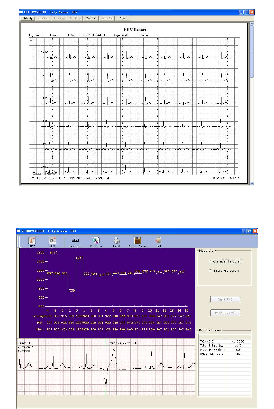
SE-1010 PC ECG User Manual Operation Instructions for Resting ECG
- 76 -
Figure 6-23 HRV Preview Screen
6.6.6 Analyzing HRT
Click on HRT to display the HRT ECG analysis screen.
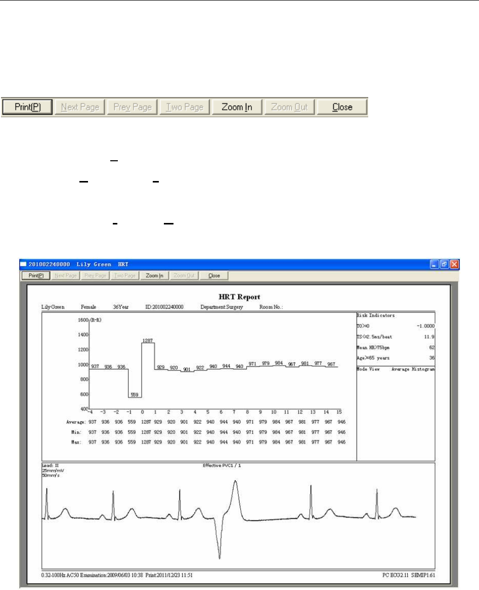
SE-1010 PC ECG User Manual Operation Instructions for Resting ECG
- 77 -
You can select Average Histogram or Single Histogram in Mode View field.
Click on Next PVC or Previous PVC to see the Next or Previous PVC wave and the relevant
histogram.
Click on the Preview button to open the HRT preview screen.
is the toolbar on the
HRT preview screen.
1. Click on Print(P) to print the report.
2. Click on Next Page/Prev Page to switch to the previous/next preview page.
3. Click on Two Page to preview two pages on one screen simultaneously.
4. Click on Zoom In/ Zoom Out to magnify/minify the preview page.
5. Click on Close to close the preview screen and return to the previous screen.
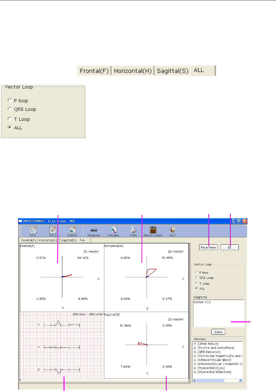
SE-1010 PC ECG User Manual Operation Instructions for Resting ECG
- 78 -
6.6.7 Analyzing Vector ECG
Click on the VCG button on the ECG analysis screen to display the VCG analysis screen. Vector
ECG displays 3D image of ECG activity.
You can choose the plane and the vector loop
on the VCG analysis screen. Plane choices include Frontal (F),
Horizontal (H), Sagittal(S) and ALL. Loop choices include P loop, QRS loop, T loop and
ALL.
6.6.7.1 Displaying Vector ECG with All Plane and All Loop
Set the plane to ALL and the loop to ALL.
Figure 6-24 Vector ECG - Plane of ALL and Loop of ALL
D C
A B E F
G
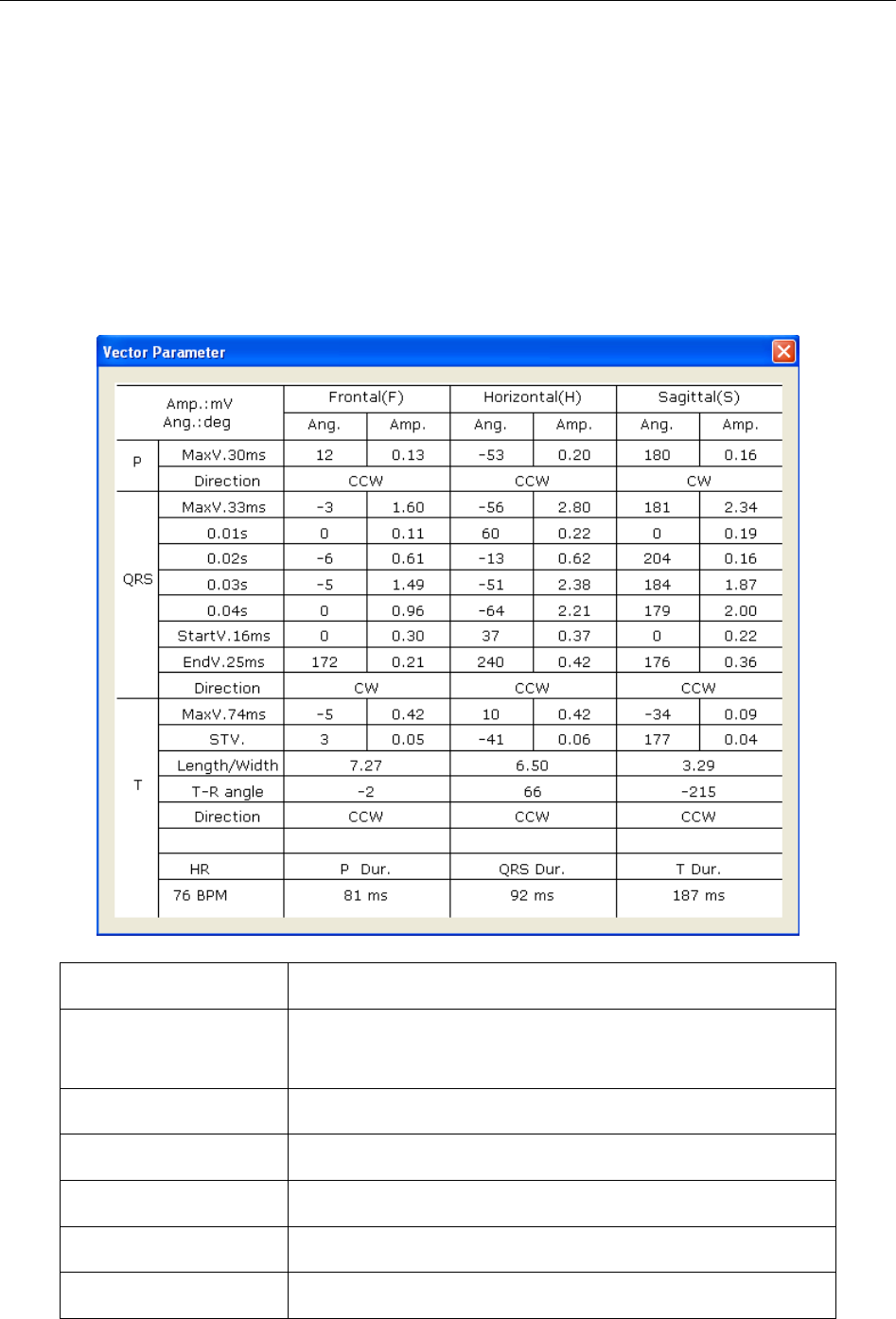
SE-1010 PC ECG User Manual Operation Instructions for Resting ECG
- 79 -
Figure 6-24 displays Vector ECG with the plane of ALL and the loop of ALL.
A- Vector ECG of Frontal (F)
B- Vector ECG of Horizontal (H)
C- Vector ECG of Sagittal (S)
D- Average templates of X, Y and Z leads. Double-click on this figure to display the magnified
average template. You can drag these lines marked P1, P2, Q, S, T1 and T2 on the wave. With the
change of the line position, the corresponding parameter values change.
E- Click on the Parameter button to display the following Vector ECG parameter list.
Designation Definition
Max Vector The position of the maximal amplitude of QRS/P/T loop
(mV)
Amplitude The amplitude of the Max vector of QRS/P/T loop (mV)
Angle The angle of the Max vector of QRS/P/T loop (degree)
Direction Rotation direction of QRS/P/T loop
CW Clockwise
CCW Counter-clockwise