EDAN INSTRUMENTS IT20EDAN Telemetry Transmitter User Manual MFM CMS
EDAN INSTRUMENTS, INC. Telemetry Transmitter MFM CMS
Exhibit 08 Users Manual

About this Manual
P/N: 01.54.456527
MPN: 01.54.456527011
Release Date: January 2015
© Copyright EDAN INSTRUMENTS, INC. 2014-2015. All rights reserved.
Statement
This manual will help you understand the operation and maintenance of the product better. It is
reminded that the product shall be used strictly complying with this manual. User’s operation
failing to comply with this manual may result in malfunction or accident for which EDAN
INSTRUMENTS, INC. (hereinafter called EDAN) can not be held liable.
EDAN owns the copyrights of this manual. Without prior written consent of EDAN, any
materials contained in this manual shall not be photocopied, reproduced or translated into other
languages.
Materials protected by the copyright law, including but not limited to confidential information
such as technical information and patent information are contained in this manual, the user shall
not disclose such information to any irrelevant third party.
The user shall understand that nothing in this manual grants him, expressly or implicitly, any
right or license to use any of the intellectual properties of EDAN.
EDAN holds the rights to modify, update, and ultimately explain this manual.
Responsibility of the Manufacturer
EDAN only considers itself responsible for any effect on safety, reliability and performance of
the equipment if:
Assembly operations, extensions, re-adjustments, modifications or repairs are carried out by
persons authorized by EDAN, and
The electrical installation of the relevant room complies with national standards, and
The instrument is used in accordance with the instructions for use.
Upon request, EDAN may provide, with compensation, necessary circuit diagrams, and other
information to help qualified technician to maintain and repair some parts, which EDAN may
I
define as user serviceable.
Terms Used in this Manual
This guide is designed to give key concepts on safety precautions.
WARNING
A WARNING label advises against certain actions or situations that could result in personal
injury or death.
CAUTION
A CAUTION label advises against actions or situations that could damage equipment, produce
inaccurate data, or invalidate a procedure.
NOTE
A NOTE provides useful information regarding a function or a procedure.
II
Table of Contents
Chapter 1 Intended Use and Safety Guidance ............................................................................ 1
1.1 Intended Use/Indications for Use ........................................................................................ 1
1.2 Safety Guidance .................................................................................................................. 1
1.3 Explanation of Symbols on the Telemetry transmitter ........................................................ 6
Chapter 2 Overview ....................................................................................................................... 8
2.1 System Introduction ............................................................................................................ 8
2.2 Display Screen of Telemetry Transmitter............................................................................ 8
2.2.1 Default Interface........................................................................................................ 8
2.2.2 Main Interface ........................................................................................................... 9
2.2.3 Setting Interface ...................................................................................................... 12
2.3 Appearance of Telemetry Transmitter ............................................................................... 12
2.3.1 Front View ............................................................................................................... 12
2.3.2 Rear View ................................................................................................................ 14
2.3.3 Left Side View ......................................................................................................... 15
2.3.4 Right Side View ...................................................................................................... 15
2.3.5 Top View ................................................................................................................. 16
2.3.6 Bottom View ........................................................................................................... 16
2.4 Configuration .................................................................................................................... 16
2.5 Display Screens of the MFM-CMS................................................................................... 17
2.5.1 Overview ................................................................................................................. 17
2.5.2 Main Screen ............................................................................................................ 17
2.5.3 Auxiliary Screen ...................................................................................................... 20
2.5.4 Large Font Display .................................................................................................. 22
2.5.5 Layout of Patient Sectors ........................................................................................ 23
Chapter 3 Installation of Telemetry Monitoring System .......................................................... 24
3.1 Initial Inspection................................................................................................................ 24
3.2 Installation Environment ................................................................................................... 24
3.3 Power Supply Requirement............................................................................................... 24
3.4 Wireless Network .............................................................................................................. 25
3.5 Installation Method ........................................................................................................... 25
3.6 Checking the Printer .......................................................................................................... 26
3.7 Checking the Telemetry Monitoring System .................................................................... 26
3.8 Setting Date and Time ....................................................................................................... 26
III
3.9 Handing Over the Central Monitoring Systerm ................................................................ 27
Chapter 4 Basic Operations ........................................................................................................ 29
4.1 Basic Operations for Telemetry Transmitter ..................................................................... 29
4.1.1 Battery Installing and Replacing ............................................................................. 29
4.1.2 Switching On ........................................................................................................... 30
4.1.3 Switching Off .......................................................................................................... 30
4.1.4 Open/ Close Screen ................................................................................................. 30
4.1.5 Leather Cover Wearing ........................................................................................... 31
4.1.6 Nurse Call ............................................................................................................... 31
4.2 Basic Operations for MFM-CMS ..................................................................................... 31
4.2.1 Mouse Operation ..................................................................................................... 31
4.2.2 Switching on/off the MFM-CMS ............................................................................ 32
Chapter 5 Patient Management .................................................................................................. 34
5.1 Admitting a Patient ............................................................................................................ 34
5.2 Changing Patient Information ........................................................................................... 34
5.3 Switching Patient sector .................................................................................................... 35
5.4 Discharging a Patient ........................................................................................................ 35
5.5 Transferring a Patient ........................................................................................................ 35
5.6 Monitoring Statistics ......................................................................................................... 35
5.7 Nurse Call / Patient Call .................................................................................................... 36
Chapter 6 Patient Sector ............................................................................................................. 37
6.1 Overview ........................................................................................................................... 37
6.2 Networked Monitoring Display ........................................................................................ 37
6.3 Menu in the Patient Sector ................................................................................................ 39
6.4 Parameter/ Waveform Setup .............................................................................................. 39
6.4.1 Setting Waveforms .................................................................................................. 39
6.4.2 Setting Parameters ................................................................................................... 40
6.5 Freeze ................................................................................................................................ 40
6.6 Real-Time Printing ............................................................................................................ 40
6.7 Alarm Reset ....................................................................................................................... 41
Chapter 7 Viewing Single Bed ..................................................................................................... 42
7.1 Display of Single Bed ....................................................................................................... 42
7.2 Hiding/Showing Multi-Lead Waveform ........................................................................... 43
7.3 Short Trend Review .......................................................................................................... 43
7.4 OxyCRG ............................................................................................................................ 44
IV
7.5 Freeze ................................................................................................................................ 44
Chapter 8 Setting Telemetry Transmitters via MFM-CMS .............................................................. 45
8.1 Changing Patient Information ........................................................................................... 45
8.2 Setting Parameters ............................................................................................................. 45
8.2.1 Parameters Alarm Setting ........................................................................................ 46
8.2.2 Physiological Parameter Attribute and Configuration ............................................ 46
Chapter 9 Review ......................................................................................................................... 47
9.1 Patient List ........................................................................................................................ 47
9.1.1 Patient Review ........................................................................................................ 47
9.1.2 History Patient Review ........................................................................................... 47
9.1.3 Backup Patient Review ........................................................................................... 48
9.2 Wave Review ..................................................................................................................... 48
9.2.1 Reviewing Normal Waveforms ............................................................................... 48
9.2.2 Reviewing Compressed Waveforms ....................................................................... 48
9.2.3 Setting Wave Speed ................................................................................................. 49
9.2.4 Refreshing Waveform ............................................................................................. 49
9.2.5 Selecting Waveform ................................................................................................ 49
9.2.6 Print ......................................................................................................................... 49
9.3 Alarm Review.................................................................................................................... 49
9.3.1 Locking and Unlocking Alarm Information ............................................................ 49
9.3.2 Printing Alarm Information ..................................................................................... 50
9.3.3 Sequencing the Alarm List ...................................................................................... 50
9.3.4 Annotating Alarm .................................................................................................... 50
9.3.5 Filtering Alarm Events ............................................................................................ 50
9.4 Trend Review .................................................................................................................... 51
9.4.1 Setting Resolution ................................................................................................... 51
9.4.2 Viewing Parameters selectively .............................................................................. 51
9.4.3 Refreshing Data ....................................................................................................... 51
9.4.4 Printing Trend Review ............................................................................................ 51
9.4.5 Selecting Trend Table, Trend Graph ....................................................................... 51
Chapter 10 System Setup ............................................................................................................. 52
10.1 Common Setup ................................................................................................................ 52
10.1.1 Color Setup ........................................................................................................... 52
10.1.2 Display Setup ........................................................................................................ 52
10.1.3 Telemetry Module Switch Setup ........................................................................... 52
V
10.1.4 Help ....................................................................................................................... 53
10.2 User Maintain .................................................................................................................. 53
10.2.1 Telemetry Transmitter Batch Settings ................................................................... 53
10.2.2 Telemetry Alarm Latch Setup ............................................................................... 53
10.2.3 Date/Time Setup .................................................................................................... 54
10.2.4 MFM-CMS System Alarm Setup .......................................................................... 54
10.2.5 Changing Language .............................................................................................. 54
10.2.6 HL7 ....................................................................................................................... 54
10.2.7 Database Maintain ................................................................................................. 55
10.2.8 Other Setups .......................................................................................................... 55
10.2.9 User Password Setting........................................................................................... 55
10.2.10 About ................................................................................................................... 55
Chapter 11 Alarm Management ................................................................................................. 56
11.1 Overview ......................................................................................................................... 56
11.1.1 Physiological Alarms............................................................................................. 56
11.1.2 Technical Alarms ................................................................................................... 56
11.1.3 Prompts.................................................................................................................. 57
11.2 Alarm Levels ................................................................................................................... 57
11.3 Parameters Alarm Setting ................................................................................................ 57
11.4 Alarm Mute ..................................................................................................................... 57
11.5 Audio Pause ..................................................................................................................... 58
11.6 Alarm Prompt/Response .................................................................................................. 58
11.7 Testing Alarms ................................................................................................................. 59
11.8 Alarms for Networking Status ......................................................................................... 60
Chapter 12 Alarm Information ................................................................................................... 61
12.1 Physiological Alarm Information .................................................................................... 61
12.2 Technical Alarm Information .......................................................................................... 63
12.3 Prompts ........................................................................................................................... 66
12.4 Adjustable Range of Alarm Limits .................................................................................. 66
Chapter 13 Printing ..................................................................................................................... 68
13.1 Printing Report with a Printer ......................................................................................... 68
13.2 Printing Preview/ Printing Settings ................................................................................. 68
13.2.1 Printing Preview .................................................................................................... 68
13.2.2 Printing Settings .................................................................................................... 68
13.3 Exporting the PDF File ................................................................................................... 68
VI
Chapter 14 Database Management ............................................................................................ 70
14.1 Database Backup ............................................................................................................. 70
14.2 Reviewing Backup Database........................................................................................... 70
Chapter 15 Monitoring ECG ...................................................................................................... 71
15.1 Overview ......................................................................................................................... 71
15.2 ECG Safety Information ................................................................................................. 71
15.3 ECG Display ................................................................................................................... 72
15.3.1 ECG Display on Telemetry Transmitter Screen .................................................... 72
15.3.2 ECG Display on MFM-CMS ................................................................................ 73
15.4 Selecting Calculation Lead ............................................................................................. 73
15.5 Changing Size of ECG Waveform .................................................................................. 74
15.6 Changing ECG Filter Settings ......................................................................................... 74
15.7 ECG Alarm Settings ........................................................................................................ 74
15.8 Monitoring Procedure ..................................................................................................... 75
15.8.1 Preparation ............................................................................................................ 75
15.8.2 Connecting ECG Cables ....................................................................................... 75
15.9 Installing Electrodes ........................................................................................................ 75
15.9.1 Electrode Placement for 3-lead ............................................................................. 76
15.9.2 Electrode Placement for 5-lead ............................................................................. 76
15.10 Setting Alarm Source .................................................................................................... 78
15.11 Smart Lead Off .............................................................................................................. 78
15.12 Setting Pace Status ........................................................................................................ 79
15.13 ECG Calibration ............................................................................................................ 79
15.14 ECG Waveform Settings ............................................................................................... 79
15.15 ST Segment Monitoring ................................................................................................ 80
15.15.1 Open/ Close ST Analysis .................................................................................... 80
15.15.2 ST Display ........................................................................................................... 80
15.15.3 ST Alarm Settings ............................................................................................... 80
15.15.4 About ST Measurement Points ............................................................................ 80
15.16 Arr. Monitoring ............................................................................................................. 81
15.16.1 Arrhythmia Analysis ........................................................................................... 81
15.16.2 ARR Analysis Menu ............................................................................................ 82
Chapter 16 Monitoring RESP ..................................................................................................... 84
16.1 Overview ......................................................................................................................... 84
16.2 RESP Safety Information ................................................................................................ 84
VII
16.3 Electrode Placement for Monitoring RESP .................................................................... 84
16.4 Cardiac Overlay .............................................................................................................. 85
16.5 Chest Expansion .............................................................................................................. 85
16.6 Abdominal Breathing ...................................................................................................... 85
16.7 Selecting RESP Lead ...................................................................................................... 85
16.8 Changing the Apnea Time ............................................................................................... 85
16.9 Changing the Size and Speed of the Respiration Waveform .......................................... 86
16.10 RESP Alarm Settings .................................................................................................... 86
Chapter 17 Monitoring SpO2 ...................................................................................................... 87
17.1 Overview ......................................................................................................................... 87
17.2 SpO2 Safety Information ................................................................................................. 87
17.3 Measuring SpO2 .............................................................................................................. 88
17.4 Measurement Procedure .................................................................................................. 88
17.5 Assessing the Validity of a SpO2 Reading ....................................................................... 89
17.6 SpO2 Alarm Delay ........................................................................................................... 90
17.7 Setting Sensitivity ........................................................................................................... 90
17.8 SpO2 Alarm Settings ....................................................................................................... 90
Chapter 18 Monitoring PR .......................................................................................................... 91
18.1 Overview ......................................................................................................................... 91
18.2 Selecting the Active Alarm Source ................................................................................. 91
18.3 PR Alarm Settings ........................................................................................................... 91
Chapter 19 Using Battery ............................................................................................................... 92
19.1 Battery Status on Screen ................................................................................................. 92
19.2 Replacing the Battery ...................................................................................................... 94
19.3 Recycling the Battery ...................................................................................................... 94
Chapter 20 Safety ......................................................................................................................... 95
20.1 Control and Safety Index ................................................................................................ 95
20.2 Characteristics ................................................................................................................. 95
Chapter 21 Care and Cleaning ................................................................................................... 96
21.1 General Points ................................................................................................................. 96
21.2 Cleaning .......................................................................................................................... 96
21.2.1 Cleaning the Telemetry Transmitter ...................................................................... 97
21.2.2 Cleaning the Reusable Accessories ....................................................................... 97
21.3 Disinfection ..................................................................................................................... 98
21.3.1 Disinfecting the Telemetry Transmitter................................................................. 98
VIII
21.3.2 Disinfecting the Reusable Accessories.................................................................. 98
Chapter 22 Maintenance ........................................................................................................... 100
22.1 Inspecting ...................................................................................................................... 100
22.2 Maintenance Task and Test Schedule ............................................................................ 100
Chapter 23 Warranty and Service ............................................................................................ 101
23.1 Warranty ........................................................................................................................ 101
23.2 Contact information ...................................................................................................... 101
Chapter 24 Accessories .............................................................................................................. 102
24.1 ECG Accessories ........................................................................................................... 102
24.2 SpO2 Accessories .......................................................................................................... 103
24.3 Other Accessories .......................................................................................................... 104
A Product Specifications ............................................................................................................ 105
A.1 Classification of Telemetry Transmitter ......................................................................... 105
A.2 Specifications of Telemetry Transmitter ........................................................................ 105
A.2.1 Physical Specifications ......................................................................................... 105
A.2.2 Environmental Specifications .............................................................................. 105
A.2.3 Display Specifications .......................................................................................... 106
A.2.4 Battery .................................................................................................................. 106
A.3 Data Storage ................................................................................................................... 107
A.4 Specifications of MFM-CMS ......................................................................................... 107
A.4.1 Recommended Hardware Configuration .............................................................. 107
A.4.2 Software Performance .......................................................................................... 109
A.5 ECG ................................................................................................................................ 109
A.6 RESP .............................................................................................................................. 114
A.7 SpO2 ............................................................................................................................... 115
A.8 Wi-Fi............................................................................................................................... 116
B EMC Information ................................................................................................................... 117
B.1 Electromagnetic Emissions ............................................................................................ 117
B.2 Electromagnetic Immunity ............................................................................................. 117
B.3 Electromagnetic Immunity ............................................................................................. 119
B.4 Recommended Separation Distances ............................................................................. 120
C Default Settings ....................................................................................................................... 122
C.1 Patient Information Default Settings .............................................................................. 122
C.2 Alarm Default Settings (MFM-CMS) ............................................................................ 122
C.3 ECG Default Settings ..................................................................................................... 122
IX
C.4 RESP Default Settings .................................................................................................... 123
C.5 SpO2 Default Settings ..................................................................................................... 124
C.6 PR Default Settings ........................................................................................................ 124
D Abbreviation ........................................................................................................................... 125
X

Telemetry Transmitter User Manual Intended Use and Safety Guidance
Chapter 1 Intended Use and Safety Guidance
1.1 Intended Use/Indications for Use
Telemetry transmitter (hereinafter called iT20) must work with central monitoring system
(hereinafter called MFM-CMS) manufactured by EDAN.
Telemetry transmitter is intended to be used in clinical divisions of hospital environments,
including CCU and general wards (as Cardiology Dept., Respiratory Dept.). It is intended to be
used for adults and pediatrics. The monitored physiological parameters include: ECG, respiration
(RESP), oxygen saturation of arterial blood (SpO2) and pulse rate (PR).
1.2 Safety Guidance
Federal (U.S.) law restricts this device to sale by or on the order of a physician.
WARNING
1 Before using the device, the equipment, patient cable and electrodes etc. should be
checked. Replacement shall be taken if there is any evident defect or signs of aging
which may impair the safety or performance.
2 The electrodes expired are forbidden to be used.
3 Medical technical equipment such as telemetry monitoring system must only be used
by persons who have received adequate training in the use of such equipment and
who are capable of applying it properly. The user should have access to, and fully
read user manual (this book) before use. Harm to patient may occur if users’
operating is not in accordance with user manual.
4 It is prohibited that the operator touches battery and patient simultaneously.
5 Do not use the device with electrosurgical unit simultaneously.
6 EXPLOSION HAZARD-Do not use the device in a flammable atmosphere where
concentrations of flammable anesthetics or other materials may occur.
7 SHOCK HAZARD-To avoid the RISK of electric shock, MFM-CMS must only be
connected to a SUPPLY MAINS with protective earth. Never adapt the three-prong
plug from the MFM-CMS to fit a two-slot outlet.
8 Under simultaneous use of cardiac pacemaker and other patient-connected
equipment, the pacing impulse analysis function must be switched ON. Otherwise, the
pacing impulse may be counted as regular QRS complexes, which could prevent an
asystole event from being detected or could lead to false alarm of asystole.
9 Do not come into contact with the patient, table, or the telemetry transmitter during
defibrillation.
- 1 -

Telemetry Transmitter User Manual Intended Use and Safety Guidance
WARNING
10 Extreme care must be exercised when applying medical electrical equipment. Many
parts of the human/machine circuit are conductive, such as the patient, connectors,
electrodes, transducers. It is very important that these conductive parts do not come
into contact with other grounded, conductive parts when connected to the isolated
patient input of the device. Such contact would bridge the patient's isolation and
cancel the protection provided by the isolated input. In particular, there must be no
contact of the neutral electrode and ground.
11 Magnetic and electrical fields are capable of interfering with the proper performance
of the device. For this reason make sure that all external devices operated in the
vicinity of the telemetry transmitter comply with the relevant EMC requirements. X-ray
equipment or MRI devices are a possible source of interference as they may emit
higher levels of electromagnetic radiation.
12 Route all cables away from patient’s throat to avoid possible strangulation.
13 Two batteries must be used as power supply.
14 Do not rely exclusively on the audible alarm system for patient monitoring. Adjustment
of alarm volume to a low level or off during patient monitoring may result in a hazard
to the patient. Remember that the most reliable method of patient monitoring
combines close personal surveillance with correct operation of monitoring equipment.
15 Accessory equipment connected to the analog and digital interfaces must be certified
according to the respective IEC/EN standards. Furthermore all configurations shall
comply with the valid version of the standard IEC/EN 60601-1. Therefore anybody,
who connects additional equipment to the signal input or output connector to
configure a medical system, must make sure that it complies with the requirements of
the valid version of the system standard IEC/EN60601-1. If in doubt, consult our
technical service department or your local distributor.
16 Telemetry transmitter is connected to MFM-CMS via wireless network. Therefore, any
other equipment complying with CISPR radiation requirements may also interfere with
the wireless communication and make it interrupted.
17 Telemetry transmitter will sent technical alarm information of low battery power to
MFM-CMS informing user of changing battery when battery power is 0-level.
Meanwhile, telemetry transmitter gives out a periodic sound of “du-du-du” whose
interval is 10 seconds till shutdown. After shutdown, module configuration and patient
information can be saved. User should restart the device after changing battery.
18 Clinical decision making based on the output of the device is left to the discretion of
the provider.
WARNING
- 2 -

Telemetry Transmitter User Manual Intended Use and Safety Guidance
19 Only use patient cable and other accessories supplied by EDAN. Or else, the
performance and electric shock protection cannot be guaranteed, and the patient may
be injured. Prior to use, check if the casing of a disposable or sterilized accessory is
intact. Do not use it if its casing is damaged.
20 Wireless LAN equipment contains an intentional RF radiator that has the potential of
interfering with other medical equipment, including patient implanted devices. Be sure
to perform the electromagnetic compatibility test, as described in the Wireless LAN
System Installation, before installation and any time new medical equipment is added
to the Wireless LAN coverage area.
21 When interfacing with other equipment, a test for leakage current must be performed
by qualified biomedical engineering personnel before using with patients.
22 If multiple instruments are connected to a patient, the sum of the leakage currents
must not exceed the limits; or it may result in shock hazard.
23 During monitoring, if the power supply is off and there is no battery for standby, the
telemetry transmitter will be off. Last settings used will be recovered when the power
is restored.
24 When leakage or foul odor is detected,stop using and keep away from fire
immediately.
25 The device and accessories are to be disposed of according to local regulations after
their useful lives. Alternatively, they can be returned to the dealer or the manufacturer
for recycling or proper disposal. Batteries are hazardous waste. Do NOT dispose
them together with house-hold garbage. At the end of their life hand the batteries over
to the applicable collection points for the recycling of waste batteries. Inappropriate
disposals of waste may contaminate the environment. For more detailed information
about recycling of this product or battery, please contact your local Civic Office, or the
shop where you purchased the product.
26 The packaging is to be disposed of according to local or hospital’s regulations;
otherwise, it may cause environmental contamination. Place the packaging at the
place which is inaccessible to children.
27 After defibrillation, the ECG display recovers within 10 seconds if the correct
electrodes are used and applied based on the manufacturers’ instructions.
28 When deploying wireless network, hospital should make sure that clinicians have
acknowledged and familiarized the coverage of wireless network signal. Patients’
activity must be within that range.
29 This equipment is not intended for home usage.
30 Do not service or maintain the telemetry transmitter or any accessories during patient
monitoring.
WARNING
- 3 -

Telemetry Transmitter User Manual Intended Use and Safety Guidance
31 The 30-meter indoor barrier-free distance of distinct vision is the coverage of wireless
network connecting telemetry transmitter and MFM-CMS. Telemetry transmitter is 30
meters (distinct vision) from wireless AP.
32 Nurse call is the only one function the patient can safely use. Other functions are all
prohibited for patient to operate.
33 The patient should wear the telemetry transmitter by leather cover, and leather cover.
34 Operation of the equipment exceeding the measurement range may cause inaccurate
results.
35 Portable and mobile RF communications equipment can affect medical electrical
equipment; Refer to the recommended separation distances provided in Appendix B
EMC Information.
36 Using accessories other than those specified may result in increased electromagnetic
emission or decreased electromagnetic immunity of telemetry transmitter.
37 Telemetry transmitter should not be used adjacent to or stacked with other equipment.
If adjacent or stacked use is necessary, you must check that normal operation is
possible in the necessary configuration before you start monitoring patients.
38 Assembly of the telemetry transmitter and modifications during actual service life shall
be evaluated based on the requirements of IEC60601-1.
39 Connecting any accessory (such as external printer) or other device (such as the
computer) to telemetry transmitter makes a medical system. In that case, additional
safety measures should be taken during installation of the system, and the system
shall provide:
a) Within the patient environment, a level of safety comparable to that provided by
medical electrical equipment complying with IEC/EN 60601-1, and
b) Outside the patient environment, the level of safety appropriate for non-medical
electrical equipment complying with other IEC or ISO safety standards.
40 All the accessories connected to system must be installed outside the patient vicinity,
if they do not meet the requirement of IEC/EN 60601-1.
41 Additional multiple socket-outlet or extension cord can’t be connected to the system.
42 Only items that have been specified as part of the system or specified as being
compatible with the system can be connected to the system.
43 The appliance coupler or mains plug is used as isolation means from supply mains.
Position the MFM-CMS in a location where the operator can easily access the
disconnection device.
44 Do not touch accessible parts of non-medical electrical equipment in the patient
environment and the patient simultaneously.
WARNING
- 4 -

Telemetry Transmitter User Manual Intended Use and Safety Guidance
45 SHOCK HAZARD - Don't connect non-medical electrical equipment, which has been
supplied as a part of the system, directly to the wall outlet when the non-medical
equipment is intended to be supplied by a multiple portable socket-outlet with an
isolation transformer.
46 The telemetry transmitter is intended for use by trained healthcare professionals in
hospital environments.
47 SHOCK HAZARD - Don't connect electrical equipment, which has not been supplied
as a part of the system, to the multiple portable socket-outlet supplying the system.
CAUTION
1 Electromagnetic Interference - Ensure that the environment in which the system is
installed is not subject to any sources of strong electromagnetic interference, such as
radio transmitters, mobile telephones, etc.
2 Keep the environment clean. Avoid vibration. Keep it far away from corrosive
medicine, dust area, high temperature and humid environment.
3 Do not immerse transducers in liquid. When using solutions, use sterile wipes to avoid
pouring fluids directly on the transducer.
4 Do not sterilize telemetry transmitter or any accessories.
5 The device and reusable accessories could be sent back to the manufacturer for
recycling or proper disposal after their useful lives.
6 Remove a battery from the telemetry transmitter immediately if battery life cycle has
expired or it is not used for a long time.
7 Disposable devices are intended for single use only. They should not be reused as
performance could degrade or contamination could occur.
8 Avoid liquid splash on the device.
9 To ensure patient safety, use only parts and accessories manufactured or
recommended by EDAN.
10 Before connecting the system to the AC power, make sure the voltage and the power
frequency are consistent with the requirements indicated on the device label or in this
user manual.
11 Protect the device against mechanical damage resulting from gravitation, collision,
powerful vibration and so on.
12 Do not touch the touch screen with a sharp object.
13 A drafty environment for system installation is required.
NOTE:
- 5 -
Telemetry Transmitter User Manual Intended Use and Safety Guidance
1 Position the device in a proper location that is stable and not easy to fall or shake.
2 The telemetry transmitter can only be used on one patient at a time.
3 If the telemetry transmitter gets damp or liquid pours on it, please contact the service
personnel of EDAN.
4 This telemetry transmitter is not a device for treatment purposes.
5 The pictures and interfaces in this manual are for reference only.
6 Regular preventive maintenance should be carried out every two years. You are
responsible for any requirements specific to your country.
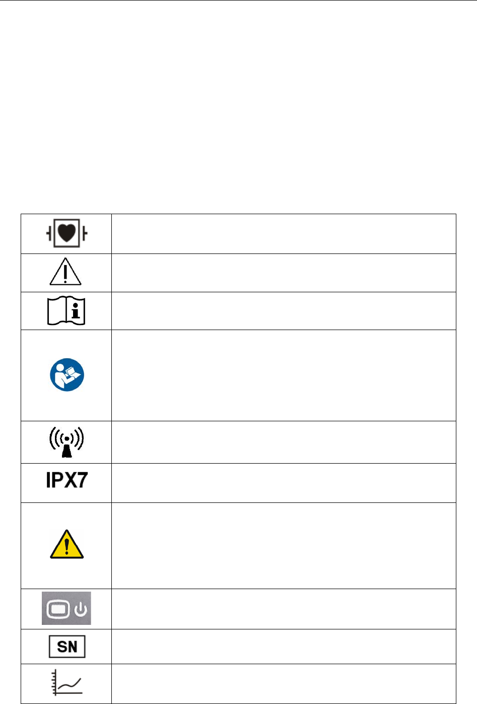
1.3 Explanation of Symbols on the Telemetry transmitter
DEFIBRILLATION-PROOF TYPE CF APPLIED PART
Caution
Operating instructions
Operating instructions
Background color---blue
Symbol color---white
The user manual is printed in black and white.
Non- ionizing electromagnetic radiation
Ingress Protection: IPX7 (protected against ingress of water with
harmful effects: temporary immersion)
General warning sign
Background color---yellow
Symbol and outline color---black
The user manual is printed in black and white.
Power Supply switch
SERIAL NUMBER
Trend
- 6 -
Telemetry Transmitter User Manual Intended Use and Safety Guidance
Picture freeze
CE marking
AUTHORISED REPRESENTATIVE IN THE EUROPEAN
COMMUNITY
Date of manufacture
MANUFACTURER
Part Number
General symbol for recovery/recyclable
Disposal method
Caution: Federal (U.S.) Law restricts this device to sale by or on the
order of a physician.
- 7 -
Telemetry Transmitter User Manual Overview
Chapter 2 Overview
2.1 System Introduction
Telemetry monitoring system can realize an integrated monitoring for multiple mobile patients or
bed patients via wireless network. It is easy for extending and net deploying. Among the system,
telemetry transmitter owns small size, light weight and long battery life and works with
MFM-CMS to form an integrated monitoring solution.
The detailed operation instructions of MFM-CMS refer to Central Monitoring System User
Manual
2.2 Display Screen of Telemetry Transmitter
The display screen of telemetry transmitter is associated with the parameters’ configuration
customer bought.
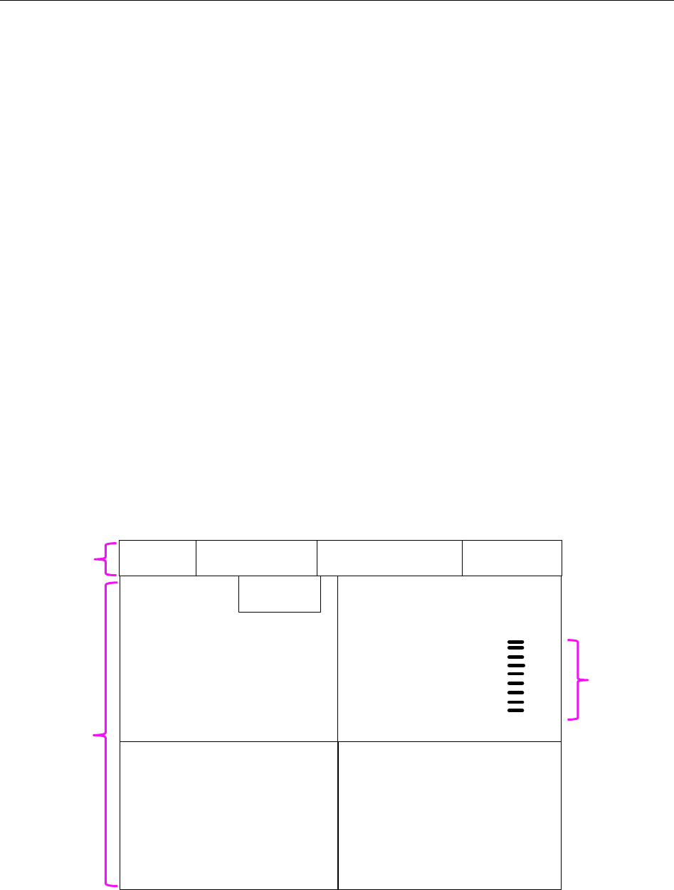
2.2.1 Default Interface
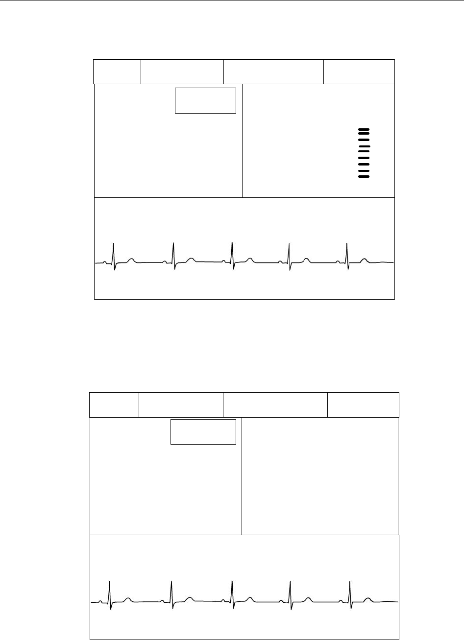
The default interface has two parts: Information Area and Parameter Value Area. Under
parameters on, the symbol ?will be displayed in parameter value area if measuring is not
implemented or the measured value is invalid. The default interface with three parameters on is as
follow:
70 SpO2 %
99
HR bpm
RR rpm
14
ST II 0.10
PR bpm
70
PACE Icon
Bed No. Networking Icon Battery Status
Wireless signal Icon
Figure 2-1 ECG + SpO2 + RESP Default Interface(ST on)
Information
Area
Parameter
Value Area
Pulse Bar Graph
- 8 -
Telemetry Transmitter User Manual Overview
2.2.2 Main Interface
Main interface has two kinds: Value - Waveform Main Interface and Trend Graph Main Interface.
Value - Waveform Main Interface
1. ECG Interface: includes information area, ECG value of calculated lead and corresponding
wave.
60
HR bpm
II
PACE Icon
Bed No. Networking Icon Battery Status
Wireless Signal Icon
Figure 2-2 ECG Interface(ST off)
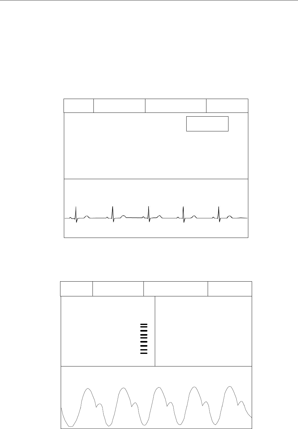
2. SpO2 Interface: includes information area, SpO2 value, PR value and PLETH wave.
SpO2 %
99
血氧波
60
HR bpm
Bed No. Networking Icon Battery Status
Wireless Signal Icon
Figure 2-3 SpO2 & PR Interface
- 9 -
Telemetry Transmitter User Manual Overview
3. ECG&SpO2 Interface: includes information area, ECG value of calculated lead, SpO2 value
and ECG wave.
60 SpO2 %
99
HR bpm
II
ST II 0.10
PACE
Icon
Bed No. Networking Icon Battery Status
Wireless Signal Icon
Figure 2-4 ECG & SpO2 Interface(ST on)
4. ECG&RESP Interface: includes information area, ECG value of calculated lead, RR value
and ECG wave.
60 RR rpm
14
HR bpm
II
ST II 0.10
PACE
Icon
Bed No. Networking Icon Battery Status
Wireless Signal Icon
Figure 2-5 ECG & RESP Interface(ST ON)
- 10 -
Telemetry Transmitter User Manual Overview
5. ECG&SpO2&RESP Interface: includes information area, ECG value of calculated lead,
SpO2 value, PR value and RR value. It’s actually the same with default interface.
70
SpO
2
%
99
HR bpm
RR rpm
14
ST II 0.10
PR bpm
70
PACE Icon
Bed No.Networking Icon Battery Status
Wireless signal Icon
Figure 2-6 ECG & SpO2 & PR & RESP Interface(ST ON)
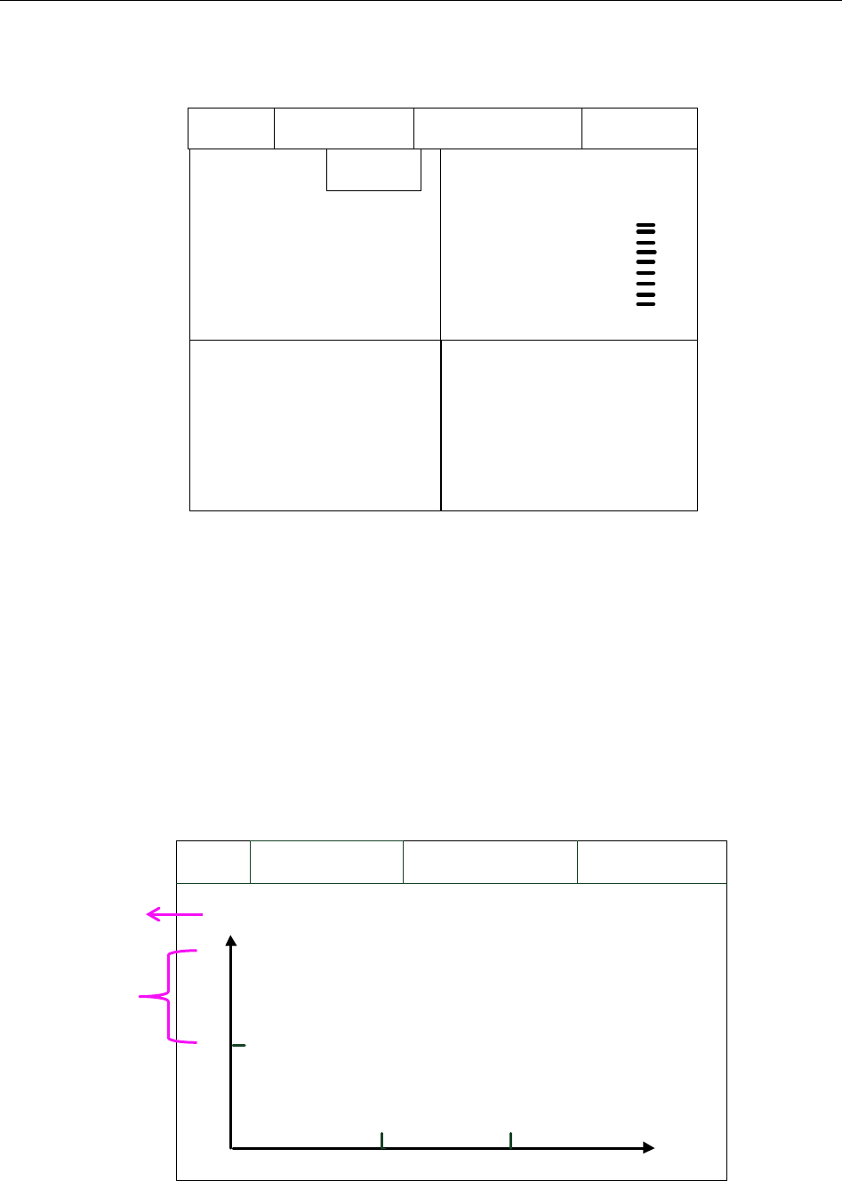
Trend Graph Main Interface
Trend Graph Main Interface can be displayed when parameters are on. It includes current
patient’s data only, not the history patient’s.
According to the parameters customer chosen, trend graph main interface has four kinds: ECG
Trend Graph Main Interface, SpO2 Trend Graph Main Interface, PR Trend Graph Main Interface
and RESP Trend Graph Main Interface.
Networking Icon
Bed No.Wireless signal Icon Battery Status
min
XXX
0
xx
-90 -60 -30
xx
Figure 2-7 Trend Graph Main Interface
Parameter name
and unit
Parameter
scale value
- 11 -
Telemetry Transmitter User Manual Overview
2.2.3 Setting Interface
Setting interface includes password inputting interface and function setting interface that will be
displayed after confirm password. Under non-0-level of battery condition, when screen is in the
setting interface, the screen can keep opened till 0 level of battery.
In setting interface, there are functions: choosing demo mode, choosing language of
telemetry transmitter, checking network configuration, upgrading operation and checking related
information of telemetry transmitter.
WARNING
1. The functions in setting interface, such as checking network configuration and
upgrading operation, are for service personnel only.
2. Demo Mode is for demonstration purposes only. You must not change into Demo
Mode during monitoring. In Demo Mode, all stored trend information is deleted from
the telemetry transmitter’s memory.
NOTE:
Multiple languages are applicable to main interface. Setting interface supports English
only.
2.3 Appearance of Telemetry Transmitter
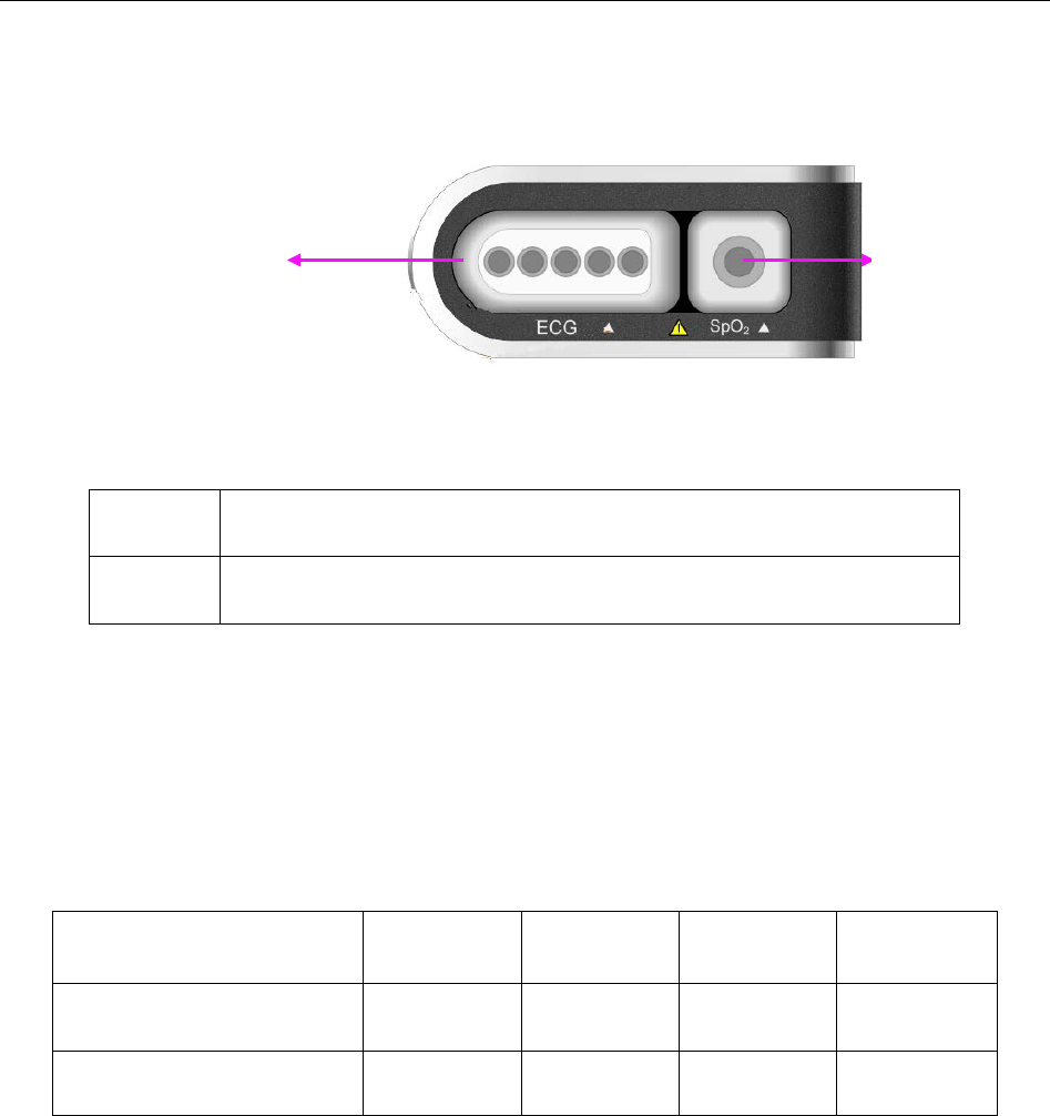
2.3.1 Front View
Front View
1
2
3
4
5
- 12 -

Telemetry Transmitter User Manual Overview
Terms explanation
Main Interface, Default Interface and Setting Interface: refer to 2.2 Display Screen of
Telemetry Transmitter.
Control focus: means the position cursor chosen by shifting key.
Focus acceptance: means user accept the position where the control focus is. It is triggered
by function acceptance key.
1 Power supply switch
Under telemetry transmitter off:
Keep pressing at least for 2 seconds to turn on and the green light on power
supply switch will occur.
Under telemetry transmitter on:
When power is in 0 level or screen is ope
n, keep pressing at least for 3
seconds to turn off.
When screen is open, press it to close screen.
Under telemetry transmitter on, when screen is closed with non-0-level of
battery, press is to open screen. (If screen is closed with 0 level of battery,
pressing it cannot open screen, and the screen will keep closed till shutdown).
2 Shifting
In main interface, press it to display between Value - Waveform Main Interface
and Trend Graph Main Interface.
In setting interface, press it to switch control focus.
When input password or choose language: ① press shifting to switch control
focus; ② press function acceptance to accept focus; ③
press shifting to
choose password or language.
In ECG leads connection sketch interface (refer to 4.1.2 Switching On), press
it to make the sketch disappear.
- 13 -

Telemetry Transmitter User Manual Overview
3 Function acceptance
In main interface, press it to return to default interface.
In setting interface, after control focus is switched to an icon, press function
acceptance to accept this function.
When input password or choose language: ① press shifting to switch control
focus; ② press function acceptance to accept focus; ③ press shifting to
choose password or language; ④ press function acceptance
to exit focus
acceptance.
1+3 Function group key (press power supply switch and function acceptance
simultaneously at least for 1second)
In main interface or in default interface, press it to display password window.
In DEMO mode, press it to exit demo mode.
4 Display screen
5 Speaker
2.3.2 Rear View
Rear View
Manufacturer’s information is listed on this side. Detailed information please refers to the
actual machine.
- 14 -
Telemetry Transmitter User Manual Overview
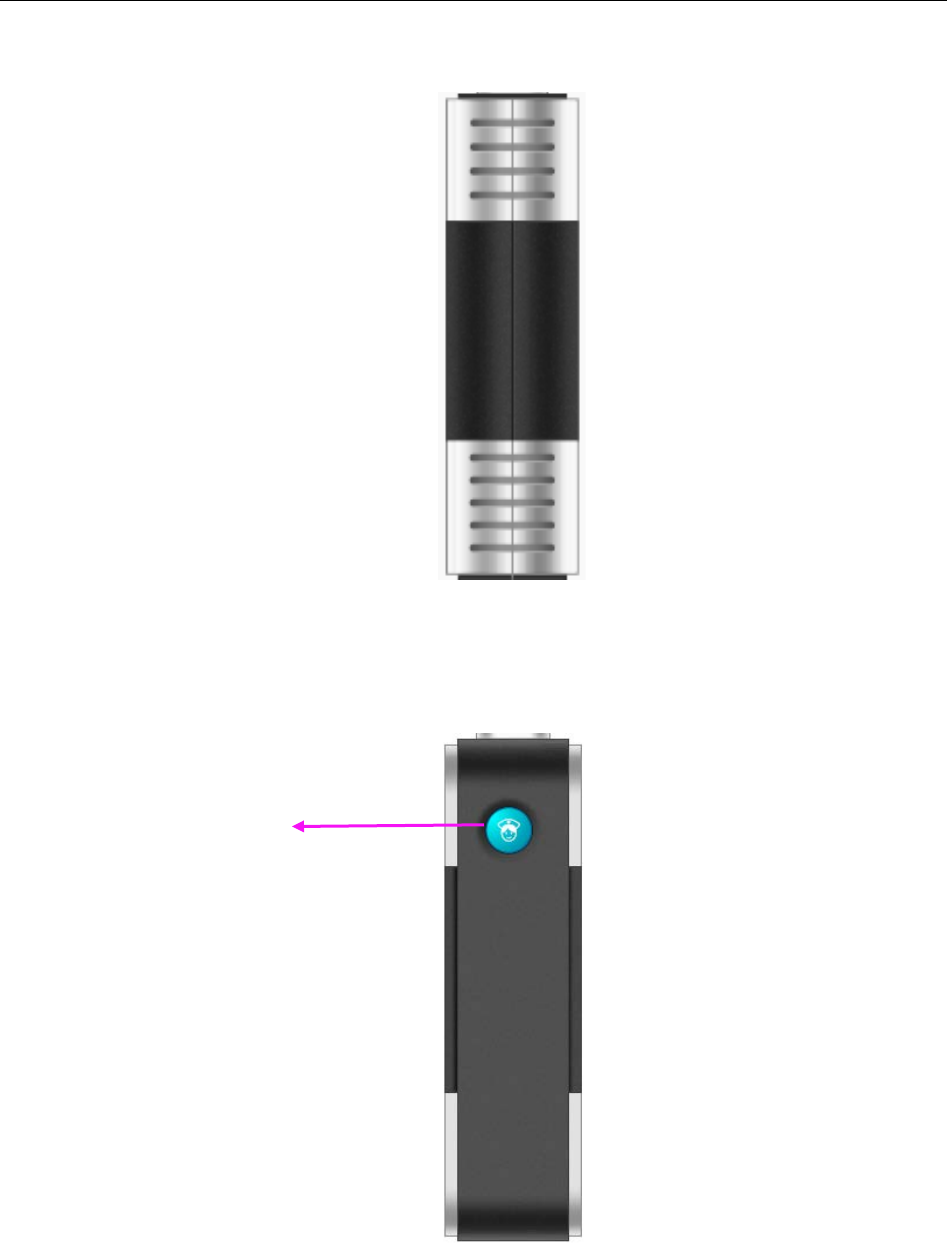
2.3.3 Left Side View
Left Side View
2.3.4 Right Side View
Right Side View
Nurse call key: press it to display calling nurse information on MFM-CMS.
Nurse call key
- 15 -
Telemetry Transmitter User Manual Overview
2.3.5 Top View
Top View
1 ECG cable connector
2 SpO2 sensor connector
2.3.6 Bottom View
Refer to 4.1.1 Battery Installing and Replacing Battery Installing and Replacing.
2.4 Configuration
The configuration of telemetry transmitter is listed below:
Function Configuration ECG SPO2 PR RESP
ECG √ × × ○
ECG & SPO2 √ ○ ○ ○
“√” means the parameter standardly configured is on by default after telemetry transmitter
switches on. Changing status should be operated on MFM-CMS. The parameter status last
used will be recovered when the device is switched on again.
“○” means the parameter standardly configured is off by default after telemetry transmitter
switches on. Changing status should be operated on MFM-CMS. The parameter status last used
will be recovered when the device is switched on again.
“×” means the parameter is not configured.
NOTE:
The parameters only standardly configured are applicable.
1
2
- 16 -
Telemetry Transmitter User Manual Overview
2.5 Display Screens of the MFM-CMS
2.5.1 Overview
The MFM-CMS can display the monitoring data using a single display or using dual displays.
The main screen and the auxiliary screen are the main operation screens. The main screen and
auxiliary screen on a single display are different from those on dual displays.
The patient sectors can be displayed in two modes: the general display mode with waveforms and
physiological parameter values displaying on the screen and the large font display mode with
only parameter values displaying on the screen. The number of patient sectors which you can
simultaneously view on the main screen and the size of the patient sectors are depended on the
layout of the patient sectors.
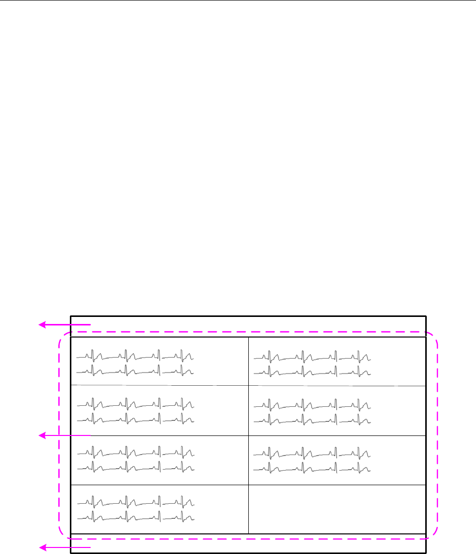
2.5.2 Main Screen
If a single display is used, the MFM-CMS system will enter the main screen for the single display
(shown as Figure 8) after the system starts up. If dual displays are used, it will enter the main
screen for dual displays (shown as Figure 9).
xx
x
xx
x
xx xx xx xx
60 99
xx
x
xx
x
xx xx xx xx
60 99
xx
x
xx
x
xx xx xx xx
60 99
xx
x
xx
x
xx xx xx xx
60 99
xx
x
xx
x
xx xx xx xx
60 99
xx
x
xx
x
xx xx xx xx
60 99
xx
x
xx
x
xx xx xx xx
60 99
1
3
2
xxxx
Figure 2-8 Main Screen on a Single Display
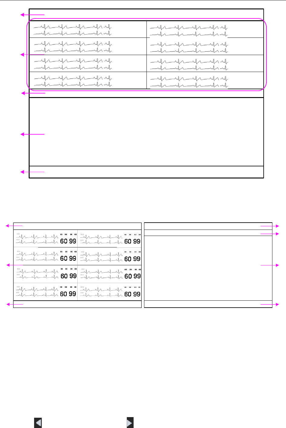
1: System information area 2: Patient sectors 3: Quick control area
- 17 -
Telemetry Transmitter User Manual Overview
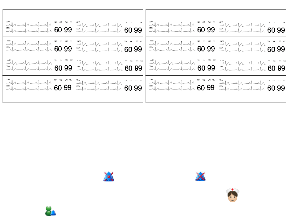
Figure 2-9 Main Screen on Dual Displays
2.5.2.1 System Information Area
The following information will be displayed in this area:
The hospital and department information.
Alarm sound pause indicator and alarm mute indicator .
When connecting with the telemetry transmitters: nurse call indicator and patient call
indicator .
Alarm information and prompts of the MFM-CMS. If more than one piece of message
occurs, they will be displayed circularly. For MFM-CMS system alarms and prompts, please
refer to Appendix II of MFM-CMS Central Monitoring System User Manual.
The system time.
2.5.2.2 Patient Sectors
A patient is monitored by a telemetry transmitter. This telemetry transmitter will occupy a patient
sector when it is connected to the MFM-CMS; meanwhile, the monitoring data will be displayed
in this patient sector. The MFM-CMS supports 64 telemetry transmitters connected to the system;
therefore, a total of 64 patient sectors are available in the MFM-CMS. The layout of patient
sectors may cause some patient sectors temporarily invisible (refer to 2.5.5 Layout of Patient
Sectors).
The patient sector has three types of state:
Network Disconnected: The black background with the white font Disconnected in a patient
sector indicates no patient is admitted or assigned to this patient sector, or the patient
assigned to this sector has been discharged.
Improper Offline: If the system is connected with telemetry transmitter, patient information,
the name of telemetry transmitter, and the message Telemetry No Signal with yellow
background are displayed in the patient sector and accompany with medium level alarm
sound. Improper Offline indicates the patient in this sector has been admitted but is offline.
- 18 -
Telemetry Transmitter User Manual Overview
Networked Monitoring: Display of patient information, waveforms, trend data and alarm
information indicates the patient in this sector has been admitted and is properly networked
and under observation.
Refer to Chapter 6 for more information about the patient sectors in networked monitoring
state.
2.5.2.3 Quick Control Area
Function Buttons
The quick control area contains the following function buttons:
Button
Button Label
Function
Main Screen Click on it to return to the main screen.
Audio Pause
Click on this symbol to make the alarm pause and the
symbol appears in place of the symbol . And click
on the symbol
to disable the pause function and the
symbol appears in place of the symbol . When the
alarm sound pauses, the symbol as well as the related
prompt will be displayed in the system information area.
Review
Click on it to enter the review interface, including patient
information review, waveform review, alarm review, trend
review.
System Setup Click on it to enter the system setup menu.
Shut Down
Click on it to shut down the MFM-CMS and the operating
system.
Admission Click on it to open the patient admission window.
System Volume
Adjustor
Click on it, and the volume adjustor icon appears.
Select the Mute check box, and
then enter the password
ABC in the text box on the pop-
up window; the entire
system become mute, and the symbol
appears. To
disable the silence function, tick the Mute check box again
and the symbol appears. Additionally, the user can drag
- 19 -

Telemetry Transmitter User Manual Overview
the volume adjustor to your desired volume.
NOTE:
MFM-
CMS will keep mute as soon as mute check box
is ticked. If a new alarm occurs, the system won’t break
mute status and keep mute until mute check box is
ticked again. Please use it with caution.
Networked State
The networked state window has 64 panes (shown as Figure 2-10) representing the 64 telemetry
transmitters that can be supported and connected to the MFM-CMS. The pane only displays the
telemetry transmitter’s number. You can access the single bed interface by clicking on the pane.
123…
…
4
Figure 2-10 Networked State
The pane has the several types of state:
Blank: Network disconnected (refer to Section 2.5.2.2 Patient Sectors).
With grey background and white bed number: Improper offline (refer to Section 2.5.2.2
Patient Sectors).
With green background: Networked monitoring (refer to Section 2.5.2.2 Patient Sectors);
without physiological alarm.
With yellow background: Networked monitoring (refer to Section 2.5.2.2 Patient Sectors);
with medium or low level physiological alarm.
With red background: Networked monitoring (refer to Section 2.5.2.2 Patient Sectors); with
high level physiological alarm.
2.5.3 Auxiliary Screen
If the patient sector is in the state either of improper offline or networked monitoring, you can
access the auxiliary screen by clicking the waveform area or parameter area on the patient sector.
The auxiliary screen on a single display is shown as Figure 2-11, and the one on dual displays is
shown as Figure 2-12.
- 20 -
Telemetry Transmitter User Manual Overview
3
2
4
1
5
xxx xx xx xx xx
60 99
xxx
xxx xx xx xx xx
60 99
xxx
xxx xx xx xx xx
60 99
xxx
xxx xx xx xx xx
60 99
xxx
xxx xx xx xx xx
60 99
xxx
xxx xx xx xx xx
60 99
xxx
xxx xx xx xx xx
60 99
xxx
xxx xx xx xx xx
60 99
xxx
Figure 2-11 Auxiliary Screen on a Single Display
1: System information area 2: Patient sectors 3: Switch and setup area for sub-window
4: Sub-window of auxiliary screen 5: Quick control area
2
1
3
1
3
5
4
Figure 2-12 Auxiliary Screen on Dual Displays
1: System information area 2: Patient sectors 3: Quick control area
3: Switch and setup area for sub-window 4: Sub-window of auxiliary screen
The auxiliary screen contains a group of sub-windows including Single Bed View, Patient
Mgmt, Wave Review, Alarm Review, Trend Review and Parameter/Waveform Setup. The
sub-window of Single Bed View will be displayed by default when you access the auxiliary
screen.
In the switch and setup area for the sub-window, you can:
Click a tag to switch the current sub-window to another sub-window.
Click to scroll leftward and click to scroll rightward in the tag bar.
- 21 -
Telemetry Transmitter User Manual Overview
Click to open the drop-down list in which you can set the tags to show/hide.
Click to exit the auxiliary screen and enter the main screen.
Drag a tag to adjust its location.
Click or to switch between full screen display mode and half screen display
mode for the auxiliary screen when using a single display.
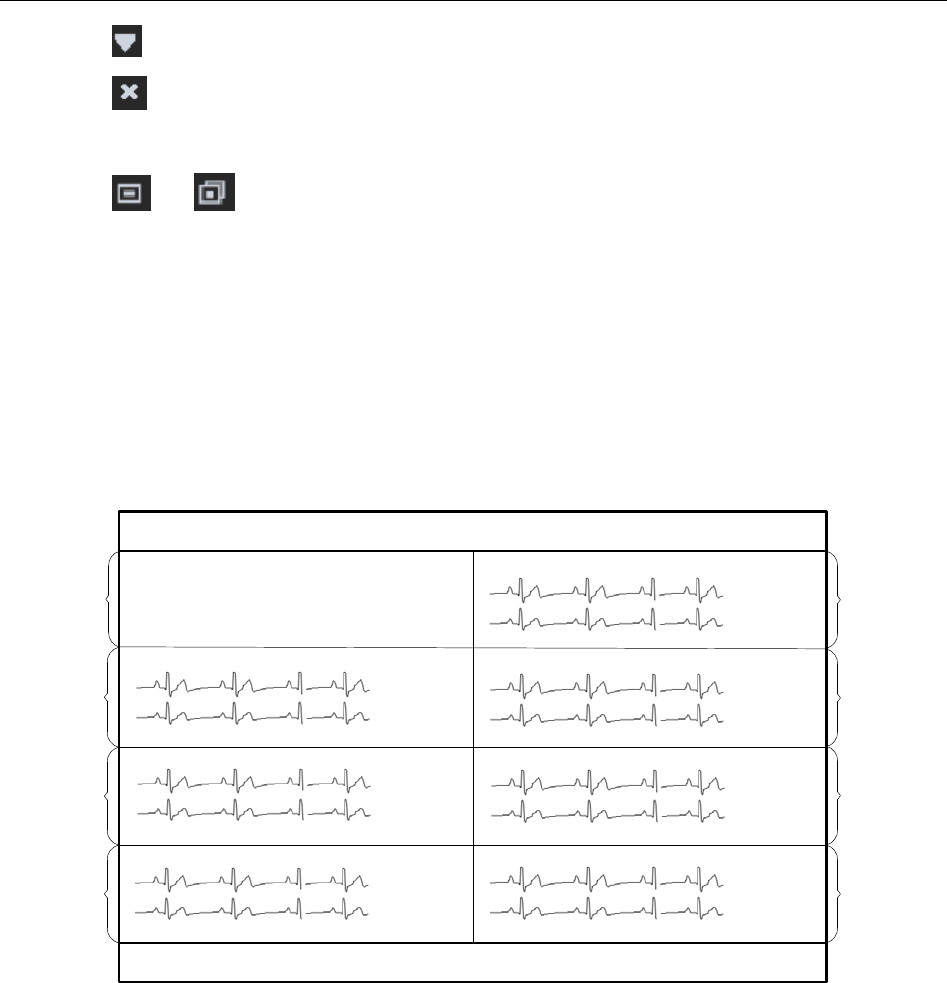
2.5.4 Large Font Display
Choose Display the window in large font from the menu in the patient sector (refer to Section
6.3 Menu in the Patient Sector), and this sector will be displayed in the large font display mode
shown as Figure 2-13. Choose Display the window in large font again, and the sector will be
displayed in the general display mode. In the large font display mode, parameter values are
displayed in the patient sector, but no waveform is shown.
xxx
xxx
xx xx xx xx
60 99
xxx
xxx
xx xx xx xx
60 99
xxx
xxx
xx xx xx xx
60 99
xxx
xxx
xx xx xx xx
60 99
xxx
xxx
xx xx xx xx
60 99
xxx
xxx
xx xx xx xx
60 99
2
3
1
4
5
6
7
8
xxx
xxx
xx xx xx xx
60 99
60 99 36.5 40
xx xx xx xx xx xx xx xx
Figure 2-13 Viewing One Patient Sector in Large Font Display Mode
1: Large font display mode 2-8: General Display Mode
Choose Display all windows in large font from the menu in the patient sector, and all sectors
will be displayed in the large font display mode shown as Figure 2-14 Choose Display all
windows in large font again, and all sectors will be displayed in the general display mode.
- 22 -

Telemetry Transmitter User Manual Overview
60 99 36.5 40
xx xx xx xx xx xx xx xx
60 99 36.5 40
xx xx xx xx xx xx xx xx
60 99 36.5 40
xx xx xx xx xx xx xx xx
60 99 36.5 40
xx xx xx xx xx xx xx xx
60 99 36.5 40
xx xx xx xx xx xx xx xx
60 99 36.5 40
xx xx xx xx xx xx xx xx
60 99 36.5 40
xx xx xx xx xx xx xx xx
60 99 36.5 40
xx xx xx xx xx xx xx xx
Figure 2-14 Viewing All Patient Sectors in Large Font Display Mode
2.5.5 Layout of Patient Sectors
The number of patients you can view on the screen and the size of each patient sector depend on
the layout of the patient sectors. If 64 telemetry transmitters are connected to the MFM-CMS and
the number of patient sectors displayed on the main screen is set to 32, the screen will only
display 32 patient sectors and the other 32 sectors are invisible. You may:
Switch between the visible and invisible patient sectors (refer to Section 5.3 Switching
Patient sector).
Click bed number to view the 64 patient sectors in the networked state window (refer to
Section 2.5.2.3 Quick Control Area).
Refer to Section 10.1.2 Display Setup for more information about setting the layout of the patient
sectors.
- 23 -

Telemetry Transmitter User Manual Installation of telemetry monitoring system
Chapter 3 Installation of Telemetry Monitoring System
NOTE:
1. The entire system must be specified by the personnel authorized by EDAN.
2. To ensure that the system works properly, please read the user manual and follow the
steps before using.
3.1 Initial Inspection
Before unpacking, check the packaging and ensure that there are no signs of mishandling or
damage. If the shipping cartons are damaged, contact the carrier for compensation and package
them again.
Open the package carefully and remove telemetry transmitter, MFM-CMS and accessories.
Check that the contents are complete and that the correct options and accessories have been
delivered.
If you have any question, please contact your local supplier.
3.2 Installation Environment
System working environment should be in consistent with the requirements in this user manual
(refer to A.2.2 Environmental Specifications).
System working should avoid noise, shock environment and the environment where the
concentrations of flammable anesthetics or other explosive materials may occur. The surrounding
of device should have enough space (at least 5 cm) to maintain and transfer heat.
NOTE:
1. Please keep the system away from radio transmitters and high power electrical and
mechanical device for those could affect monitoring.
2. Wireless transmission is applicable to the system. It’s normal that irregular waveform
due to outside interference may occur. If you have any question on Electromagnetic
environment, please contact service personnel.
3.3 Power Supply Requirement
Power supply should be in consistent with the requirements in this user manual (refer to A.2.4
Battery).
NOTE:
1 Connect the power cable of MFM-CMS to the socket specialized for hospital use.
2 Only use the power cable supplied by EDAN.
- 24 -

Telemetry Transmitter User Manual Installation of telemetry monitoring system
3.4 Wireless Network
Telemetry translator and MFM-CMS construct wireless network through AP. The qualified
engineers specified by EDAN are responsible for installing wireless network and performance
tests. For details, please refer to Patient Monitor Wireless Network Installation Guide.
NOTE:
1. Be aware that some network-based functions may be limited for telemetry transmitter
on wireless networks in comparison with those on wired networks.
2. The obstacle may interfere with data transmission and even cause data loss.
3. When telemetry transmitter has been connected to a wireless network, to make the
change of the Bed No. effective, you need to disconnect the wireless connection and
then connect it again or reboot telemetry transmitter.
3.5 Installation Method
The personnel specified by EDAN are responsible for system installation, which includes
surrounding verification, MFM-CMS installation, wireless device installation and telemetry
transmitter installation, etc.
WARNING
1. When the system is required to connected with other electric devices, and those
electric devices are not approved to be safe for connection with the system, such as
current leakage may cause electronic shock, please contact specialists in hospital or
our service personnel.
2. Upgrade operation is only for personnel authorized by EDAN.
3. Plugging three-pin into two-pin adaptor is prohibited.
4. To change installation environment or move system to another site, please contact
our service personnel.
5. The medical electrical equipment needs to be installed and put into service according
to the EMC Information provided in this user manual.
CAUTION
1. To avoid unpredictable results from sudden power interruption, please provide UPS
(Uninterruptible power supplies) for the system.
2. Keeping battery bin dry is required.
- 25 -

Telemetry Transmitter User Manual Installation of telemetry monitoring system
NOTE:
Crossover Ethernet cable is connected with computer and parallel Ethernet cable is
connected with HUB.
3.6 Checking the Printer
If an external printer is required, please confirm the printer is powered on and paper is properly
installed in the slot. If it is not powered on or no paper exists, please power the printer on
according to power requirements in MFM-CMS Central Monitoring System User Manual and put
appropriate paper.
WARNING
External device connected with system, such as printer or speaker, should be in
accordance with power requirements for system.
3.7 Checking the Telemetry Monitoring System
Make sure there is no damage on the measurement accessories and cables. Then turn on the
telemetry and MFM-CMS, check whether the system can start normally. Make sure battery for
telemetry transmitter has enough power, MFM-CMS can alarm normally and the alarm sound is
heard.
WARNING
If any signs of damage are detected, or screen displays error messages, do not use it on
any patient. Contact service center immediately.
NOTE:
1 Check all functions applicable and make sure that the system is in good status.
2 If telemetry transmitter is in low battery power status (0 level), replace battery to
ensure the electric power is enough.
3.8 Setting Date and Time
Setting and displaying date and time is applicable to MFM-CMS only.
The user can set the correct date and time and their desired format. There are three kinds of date
format: yyyy-MM-dd, dd-MM-yyyy, MM-dd-yyyy, two kinds of time format: HH-mm-ss (24
hours) and hh-mm-ss tt (12 hours), and three date separator: /, - and. To change the date and time
setup, please select Main Screen > System Setup > Common Setup > Date /Time Setup, and
select the desired settings from the right menu. The time and date displayed on the main screen
will also change after change the date and time setup and their format.
- 26 -

Telemetry Transmitter User Manual Installation of telemetry monitoring system
WARNING
During patient monitoring, a change in date and time will influence the storage of trend
data.
NOTE:
1 The user must restart MFM-CMS to make the change effective.
2 If the system is not used for a longer period of time, its system time may be
inaccurate. In this case, reset the system time after powering on.
3 If the system time cannot be saved and resumes the default value after restart,
contact the service department of EDAN.
3.9 Handing Over the Central Monitoring Systerm
If you are handing over system to the end-users directly after installation and configuration, make
sure that it is in the monitoring mode.
The users must be adequately trained to use the system before monitoring a patient. To achieve
this, they should have access to, and read, the following documentation delivered with system:
User Manual (this book) - for full operating instructions.
Quick Reference Card - for quick reminders during use.
3.10 FCC Statement
This equipment has been tested and found to comply with the limits for a Class B digital device,
pursuant to part 15 of FCC Rules. These limits are designed to provide reasonable protection
against harmful interference in a residential installation. This equipment generates and can radiate
radio frequency energy and, if not installed and used in accordance with the instructions, may
cause harmful interference to radio communications. However, there is no guarantee that
interference will not occur in a particular installation. If this equipment does cause harmful
interference to radio or television reception, which can be determined by turning the equipment
off and on, the user is encouraged to try to correct the interference by one or more of the
following measures:
1. Reorient or relocate the receiving antenna.
2. Increase the separation between the equipment and receiver.
3. Connect the equipment into an outlet on a circuit different from that to which the receiver is
connected.
4. Consult the dealer or an experienced radio/TV technician for help.
This device complies with Part 15 of FCC Rules.
Operation is subject to the following two conditions:
- 27 -

Telemetry Transmitter User Manual Installation of telemetry monitoring system
1. This device may not cause harmful interference, and
2. This device must accept any interference received, including interference that may cause
undesired operation.
NOTE:
The manufacturer is not responsible for any radio or TV interference caused by
unauthorized modifications to this equipment. Such modifications could void the user’s
authority to operate this equipment.
- 28 -
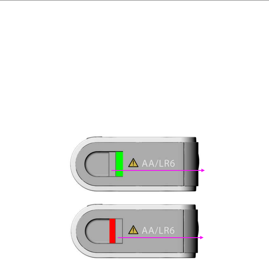
Telemetry Transmitter User Manual Basic Operations
Chapter 4 Basic Operations
The general functions for telemetry transmitter are operated on MFM-CMS, which include
chapter 5 patient management, chapter 6 patient sector, chapter 7 viewing single bed, chapter 8
setting telemetry transmitter via MFM-CMS, chapter 9 review, chapter 10 system setup, chapter
11 alarm management, chapter 12 alarm information, chapter 13 printing, and chapter 14
database management.
The following introduction is about the basic operations for telemetry transmitter and
MFM-CMS.
4.1 Basic Operations for Telemetry Transmitter
4.1.1 Battery Installing and Replacing
Bottom View
Installing:
As pictured above, move the battery compartment latch right to open battery door. Install two AA
alkaline batteries following “+” or “-” indication, and then press the door to close correctly with
“ka-ka” sound.
Replacing:
Method is the same with installing.
Under the condition that telemetry transmitter continuously works at least for 15 minutes and
moreover it has a good Wi-Fi communication (typical network environment with no interference),
the telemetry transmitter can keep power on up to 20 seconds after taking batteries out.
Battery compartment latch
Green bar occurs under
locked status.
Red bar occurs under
unlocked status.
- 29 -

Telemetry Transmitter User Manual Basic Operations
WARNING
It is prohibited for patient to install or replace battery.
4.1.2 Switching On
Under switch off condition, keep pressing power supply switch at least for 2 seconds to turn on.
Then the green light on power supply switch will occur. At the same time, the following self-tests
will be carried out:
Read parameters configuration. Refer to 2.4 Configuration for configuration information;
Check ECG accessory compatibility.
When accessory is not compatible, the screen will display “Check the ECG accessories”; When
compatible and ECG module is active, telemetry transmitter will check ECG leads connection.
The screen will enter into main interface under condition of correct leads connection. Under leads
off or wrong connection, the screen will display ECG leads connection sketch in which wrong
leads position and correct leads position will be indicated. ECG leads connection sketch will
disappear in these conditions, leads connection restoring normally, pressing shifting key or over
60 seconds.
Read automatically ECG leads type (3-lead or 5-lead) and ECG leads style (AHA or IEC).
NOTE:
During switch on, user should confirm the green light on power supply switch occurs and
screen displays normally. Nurse call and patient call sounds should also be tested
normally. Refer to 5.7 Nurse Call / Patient Call for more nurse call and patient call
information.
4.1.3 Switching Off
Under telemetry transmitter on:
When power is in 0 level or screen is open, keep pressing at least for 3 seconds to turn off..
4.1.4 Open/ Close Screen
Under telemetry transmitter on, when screen is closed with non-0-level of battery, press is to
open screen. The screen will be back to the interface last used after opening again.
Under screen open condition, do one of the following method to close:
1. Press power supply switch;
2. Without any actions in 15 seconds, screen will close automatically.
After closing, monitoring and net connection keep working normally.
- 30 -
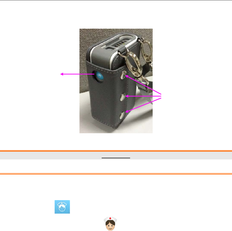
Telemetry Transmitter User Manual Basic Operations
4.1.5 Leather Cover Wearing
Telemetry transmitter supports leather cover to wear, as pictured below:
WARNING
To avoid infection or other severe results, leather cover must not touch injured skin.
4.1.6 Nurse Call
Press nurse call key on the right side. Information about nurse call will be sent to
MFM-CMS on which a nurse call symbol will be displayed to tell nurse patient’s calling.
(Refer to 5.7 Nurse Call / Patient Call)
4.2 Basic Operations for MFM-CMS
4.2.1 Mouse Operation
Usually, we use the following terms to describe mouse operation:
Left-key:
1. Click: move mouse to the target, then quickly press left-key once and release it.
2. Double-click: move mouse to the target, then quickly press left-key twice and release it.
3. Drag: move mouse to the target, press left-key and move to the destination and then release
it.
Right-key:
Nurse Call Key
Lock Button
- 31 -

Telemetry Transmitter User Manual Basic Operations
1. Click: move mouse to the target, then quickly press right-key once and release it.
2. Double-click: move mouse to the target, then quickly press right-key twice and release it.
4.2.2 Switching on/off the MFM-CMS
Starting monitoring
NOTE:
Before starting the system, please verify that the dongle has been installed. Otherwise,
you may fail to access the system.
When all of its components are correctly connected, press the power button on the front panel of
the device. The power indicator on the front panel lights up and the device performs hardware
self-test. If the device works normally, the main screen appears. If the device detects abnormity
during self-test, it beeps to show alarm and displays error information on the screen. In this case,
you should record the error information, shut down the device and contact technical
representative of EDAN. After the system self-test is completed, you will access the MFM-CMS
system interface and the system will also finish the environment self-test automatically.
Meanwhile, the system will sound Do-Do-Do, a test sound. The user should set the volume
system and confirm that the volume of the system can be heard clearly.
CAUTION
1 Ensure that the sound equipment is always in a state of activation.
2 The audio adapter and network adapter should be correctly installed, or you may not
access the MFM-CMS.
NOTE:
Ensure that the MFM-CMS system can give the test sound after startup.
Shutting down the System
It is important to shut down the system properly. Follow this simple procedure to properly shut
down your system. This prevents inadvertent errors from occurring during system shut down.
The MFM-CMS can work continuously for a long time. You do not need to shut it down in order
to achieve a longer working life.
You should follow the procedure to shut down the MFM-CMS.
Method 1:
Select Shut Down on the main menu and enter the password ABC. Confirm the password by
clicking OK, and the MFM-CMS as well as the operating system will be shut down.
- 32 -

Telemetry Transmitter User Manual Basic Operations
Method 2:
Select System Setup > User Maintain, and enter the password ABC; select Other Setup.
Select Shut Down: the MFM-CMS as well as the operating system will be shut down.
Select Return to Windows: you will exit from MFM-CMS, but the operating system will
not be shut down.
WARNING
1 Shut down the system by strictly observing the shutdown procedure to avoid serious
result.
2 Although UPS is an optional configuration of this system, if you really force to turn off
the UPS, it results in system failure and hence affects the operation of next time.
3 If power cut-off occurs, turn off the system before the UPS exhausts its electricity.
CAUTION
Hospitals without a stable power source should use a UPS to provide power to the
MFM-CMS. The UPS must not be turned off. When there is a power failure, the system
should be shut down by following the specified shutdown procedure before the UPS is
exhausted. If the system has a sudden power failure, system failure may occur and
consequently the system may not work correctly next time or even has a serious result.
NOTE:
If you forget the password, please contact the technical representative of EDAN.
- 33 -

Telemetry Transmitter User Manual Patient Management
Chapter 5 Patient Management
The contents related to this chapter are all operated on MFM-CMS.
5.1 Admitting a Patient
Once MFM-CMS starts up and telemetry transmitter is properly connected with MFM-CMS, the
system will prompt the user to admit patients by displaying the number of pending patients at the
information area.
Click Admission in the quick control area to display a window of Pending patient list. Select
the patients you want to admit from the left list in the window, and enter the patient information
in the right area of the window. Click the Admission button at the bottom of the window to
complete patient admission.
After being admitted, a patient will occupy a patient sector. The MFM-CMS displays the
real-time monitoring data which will also be stored in the database.
For the telemetry transmitter that has been offline due to network problems and is networked with
MFM-CMS later, you need not readmit the patient of this telemetry transmitter. This telemetry
transmitter will be automatically online in the patient sector which it has occupied.
WARNING
For telemetry transmitters that have been networked with MFM-CMS for the first time,
you have to complete patient admission by using the methods mentioned above, which
enables the telemetry transmitters to be online and observed by MFM-CMS. Otherwise,
the telemetry transmitters will not be online on MFM-CMS, and the monitoring data will
not be saved by MFM-CMS.
5.2 Changing Patient Information
You can change the patient information on MFM-CMS when you find the information incorrect.
To modify the patient information, choose Single Bed View > Patient Mgmt, enter the correct
information in the appropriate fields and click Update Monitor.
In the patient management window, the user can modify the patient information, such as Serial
No., Patient Name, Type, Gender, Bed No., Date of Birth and so on. After editing the
information, click on the Update Monitor button to update the changes. The patient information
can be printed when the user click on Print.
NOTE:
If you have changed the patient type via the MFM-CMS, the patient type on the telemetry
transmitter will be changed accordingly.
- 34 -

Telemetry Transmitter User Manual Patient Management
5.3 Switching Patient sector
For a disconnected patient sector (refer to Section 2.5.2.2 Patient Sectors), click anywhere in
it and choose a patient to be assigned to this section from the patient list.
For a patient sector which is either improper offline or networked (refer to Section 2.5.2.2
Patient Sectors), select Show from the list on the patient sector (refer to Sector 6.3 Menu in
the Patient Sector), and choose another telemetry transmitter from the patient list; the chosen
telemetry transmitter will be displayed in this patient sector.
5.4 Discharging a Patient
When the monitoring on a patient is completed, you need to discharge this patient by any of the
following methods:
Choose Discharge from the menu in the patient sector (refer to Section 6.3 Menu in the
Patient Sector).
Choose Patient Mgmt > Discharge on the auxiliary screen.
Discharge the patient via the Review window. Refer to Section 9.1.1 Patient Review.
The operation of discharging a patient will cause the patient offline from the MFM-CMS, and
there will be no patient admitted in the related patient sector. The discharged patient will be
shown in the history patient list. Refer to Section 9.1.2 History Patient Review.
5.5 Transferring a Patient
Select Patient Mgmt >Transfer on the auxiliary screen, and you will see a list of online patients.
From this list, select a patient whose bed will be considered as the destination bed and click OK,
and then the current patient will be transferred to the destination bed.
NOTE:
Transferring a patient to the destination bed will at the same time discharge the selected
patient on the destination bed.
5.6 Monitoring Statistics
The monitoring statistics of the selected patients will be shown in the patient management
window. The monitoring statistics covers the total monitoring time for waveforms and trends, the
number of alarm events.
Click Analysis, the system will:
Analyze the number of high and low limit alarms for each physiological parameter and
analyze the percentage of the limit alarms of the parameter in all limit alarms.
Analyze the number of arrhythmia events for each type of arrhythmia and analyze the
percentage of a certain type of arrhythmia.
Analyze the average value, maximum/minimum value, and measure time of the
maximum/minimum value for the trend values.
- 35 -

Telemetry Transmitter User Manual Patient Management
5.7 Nurse Call / Patient Call
For the telemetry transmitter connected to network, you can use the functions of nurse call and
patient call.
The MFM-CMS will response to the nurse call with a sound “du” once the patient presses the
nurse call button on the telemetry transmitter.
The nurse call indicator will be displayed in the system information area on the main
screen. You can cancel nurse call by clicking the indicator.
The nurse call symbol will appear in the patient sector and cover the waveforms. You
can cancel nurse call by clicking the symbol.
The nurse call indicator will be displayed in the indicator area in the single bed
window.
The nurse call tune will sound.
Telemetry transmitter will give a sound “du-du-du” when patient call is triggered. Patient Call
Symbol will also appear in the system information area on the main screen. You can
perform or cancel the patient call via the MFM-CMS as follows:
Choose Call Patients from the menu in the patient sector (refer to Section 6.3 Menu in the
Patient Sector) to trigger, and choose Cancel Patient Calling to cancel.
Select the tag Patient Mgmt of auxiliary screen and access the Patient Mgmt window.
Click Call Patients in this window to trigger and click Cancel Patient Calling to cancel.
After calling patients, you can also click Patient Call Symbol in the system information
area on the main screen to cancel.
- 36 -
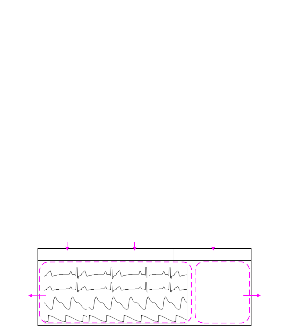
Telemetry Transmitter User Manual Patient Sector
Chapter 6 Patient Sector
The contents related to this chapter are all operated on MFM-CMS.
6.1 Overview
Refer to Section 2.5.2.2 Patient Sectors for information about the three types of state of the patient
sector. Refer to Section 2.5.4 Large Font Display for information about the large font display
mode in the patient sector. Refer to Section 2.5.2 Main Screen for information about the layout of
patient sectors.
When the patient sector is in the improper offline state or in the networked monitoring state, you
can open a menu by clicking on the patient information area. Refer to Section 6.3 Menu in the
Patient Sector for more information about the menu.
When the patient sector is in the improper offline state or in the networked monitoring state, you
can access the auxiliary screen by clicking on the waveform area or parameter area in the patient
sector.
When the patient sector is in the disconnected state, you can switch between patient sectors by
clicking on the patient sector. Refer to Section 5.3 Switching Patient sector for more information.
6.2 Networked Monitoring Display
The display of patient sector which is networked is shown as Figure 6-1.
xxx
xxx
xxx
xxx
60 99
36.5 40
xx xx xx xx
xx xx xx xx
3
12
4 5
xxx xxx xxx
Figure 6-1 Display of the Networked Patient Sector
1: Waveform area 2: Parameter area 3: Patient information area
4: Technical alarm/ Prompts/ indicator area 5: Physiological alarm area
Waveform area and parameter area: It displays some of real-time monitoring waveforms and
parameter values. Refer to Section 6.4 Parameter / Waveform Setup.
Patient information area: It displays the bed number, device name and patient name.
Technical alarm/ Prompts/ Indicator area: It displays the technical alarm messages when a
technical alarm occurs (refer to Section 11.1.2 Technical Alarms). Click on the technical
alarm message, and the list for the current technical alarms will be displayed. When no
technical alarms and no prompts occur, it displays the indicators (shown as Table 6-)
- 37 -
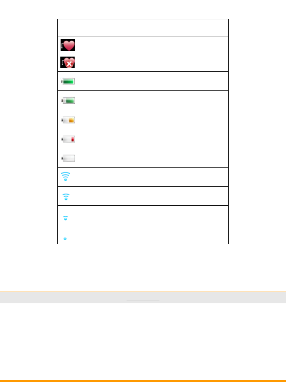
Telemetry Transmitter User Manual Patient Sector
indicating the state of the telemetry transmitters.
Indicator Description
Pace on
Pace off
Battery power of the telemeter transmitter:
Level 4
Battery power of the telemeter transmitter:
Level 3
Battery power of the telemeter transmitter:
Level 2
Battery power of the telemeter transmitter:
Level 1
Battery power of the telemeter transmitter:
Level 0
Wi-Fi signal intensity of the telemeter
transmitter: Level 4
Wi-Fi signal intensity of the telemeter
transmitter: Level 3
Wi-Fi signal intensity of the telemeter
transmitter: Level 2
Wi-Fi signal intensity of the telemeter
transmitter: Level 1
Table 6-2 Telemetry Transmitters State Indicators
Physiological alarm area: It displays the physiological alarm messages (refer to Section
11.1.1 Physiological Alarms). Click on the physiological alarm message, and the list for the
current physiological alarms will be displayed.
CAUTION
1 Due to the delay of network transmission, the waveform viewed at the MFM-CMS has
a delay of 5 seconds compared with the waveform generated at the corresponding
telemetry transmitter.
2 Due to the operating system schedule, the waveform scan of the MFM-CMS might be
suspended for about 20 milliseconds in very few occasions. After the suspension,
waveform scan will go back to normal status. The quality of patient monitoring during
the suspension will not be affected.
- 38 -

Telemetry Transmitter User Manual Patient Sector
6.3 Menu in the Patient Sector
When the patient sector is in the improper offline state or in the networked monitoring state, you
can open a menu by clicking on the patient information area. The available items in this menu
are:
Display the window in large font: Switch between the large font display mode and the
general display mode for the current patient sector. Refer to Section 2.5.4 Large Font
Display.
Display all windows in large font: Switch between the large font display mode and the
general display mode for all patient sectors. Refer to Section 2.5.4 Large Font Display.
Parameter/Waveform Setup: Switch to the Parameter/Waveform Setup window on the
auxiliary screen. Refer to Section 6.4 Parameter/ Waveform Setup.
Monitor Parameter Setup: Switch to telemetry transmitter Parameter Setup window on the
auxiliary screen. Refer to Section 8.2 Setting Parameters.
Discharge: Discharge the patient in the current patient sector. Refer to Section 5.4
Discharging a Patient.
Freeze: Freeze/ unfreeze the waveform in the current patient sector. Refer to Section 6.5
Freeze.
Print: Print the monitoring data in the current patient sector. Refer to Section 6.6 Real-Time
Printing.
Call Patients: Nurse calls patient. Refer to Section 5.7 Nurse Call / Patient Call.
Show: Switch between patient sectors. Refer to Section 5.3 Switching Patient sector.
Alarm Reset: Activate alarm reset function. Refer to Section 6.7 Alarm Reset.
6.4 Parameter/ Waveform Setup
Due to the limited display space of the patient sector, the numbers of waveforms and parameters
to be displayed depends on the numbers of telemetry transmitters displayed on patient sector
which can be set by users (refer to 10.1.2 Display Setup). 6 waveforms and 4 parameters to be
displayed on patient sector are the maximum. You can set the displayed waveforms and
parameters by setting configuration in the Parameter/Waveform Setup window. You may
access this window by either of the two methods below:
Choose Parameter/ Waveform Setup from the menu on the patient sector.
Click the tag Parameter/ Waveform Setup on the auxiliary screen.
6.4.1 Setting Waveforms
Select or deselect the check box before a Wave Name to display or not display the waveform.
Click Update Wave Setup to confirm the configuration. The patient sector will only display the
selected waveforms.
Choose Speed and set the desired sweep speed for the waveform. Click Update Wave Setup to
- 39 -

Telemetry Transmitter User Manual Patient Sector
confirm the configuration. The waveform will be displayed according to the speed you have set.
NOTE:
Waveform setting is applicable only when the relevant module switches on.
6.4.2 Setting Parameters
Adding a parameter to be displayed
To add a new parameter to be displayed, select the desired parameter name in Available Params
and click on Add to add it into Current Params, and then click on Refresh ParamGroup to
update the parameters displayed on the patient section.
Removing a parameter displayed
To remove a parameter displayed, select the parameter in the Current Params box, and click on
Remove and Refresh ParamGroup.
Setting Parameter Order for Display
To adjust the display position of the parameter, select the parameter name in the Current Params
box, and click on Move UP or Move Down. To make the change valid, click on Refresh
ParamGroup.
NOTE:
Due to the limited display space, the displayed waveforms and parameters of each
patient sector will decrease as the displayed patient sectors increase. If you want more
waveforms and parameters to be displayed in one patient sector, modify the display
layout by reducing the patient sectors displayed on the main screen.
6.5 Freeze
Choose Freeze from the menu in the patient sector, you can freeze the waveform displayed in this
patient sector. And the item name Freeze is changed into Unfreeze. You can unfreeze the
waveform by choosing Unfreeze. And then the item name will resume Freeze.
The wave stops scanning during freeze. The freeze time and a timeline will also be displayed in
the window. You can use the arrow buttons and beside the timeline or drag the pointer
on the freeze wave to review more details.
You can review a frozen waveform of 3-minute period in length.
6.6 Real-Time Printing
To print real-time data from MFM-CMS, click Print from the menu in the patient sector or click
the Print button in the single bed window.
After you select Print, MFM-CMS starts to collect data for printing and the system will indicate
Collecting Data… at the top of the main screen. After the system completes 11-second data
collecting, a dialog box for printing setup will appear. The printout includes the 11-second
waveform data starting from the time chosen as the beginning time for printing, data of all
- 40 -

Telemetry Transmitter User Manual Patient Sector
physiological parameters at the time you select Print and the latest NIBP measurement which is
the nearest from the time finishing collecting.
6.7 Alarm Reset
Choose Alarm Reset from the menu in the patient sector to activate the alarm reset function.
During the alarm reset status, MFM-CMS will do the followings:
The audio alarm is turned off, and no alarms are sounding.
The visual alarm indications are still displayed.
Clear all the latched alarms.
NOTE:
If a new alarm occurs during the alarm reset period, the new alarm on MFM-CMS will
recover normal. That is, the new alarm will be sounded and displayed.
- 41 -
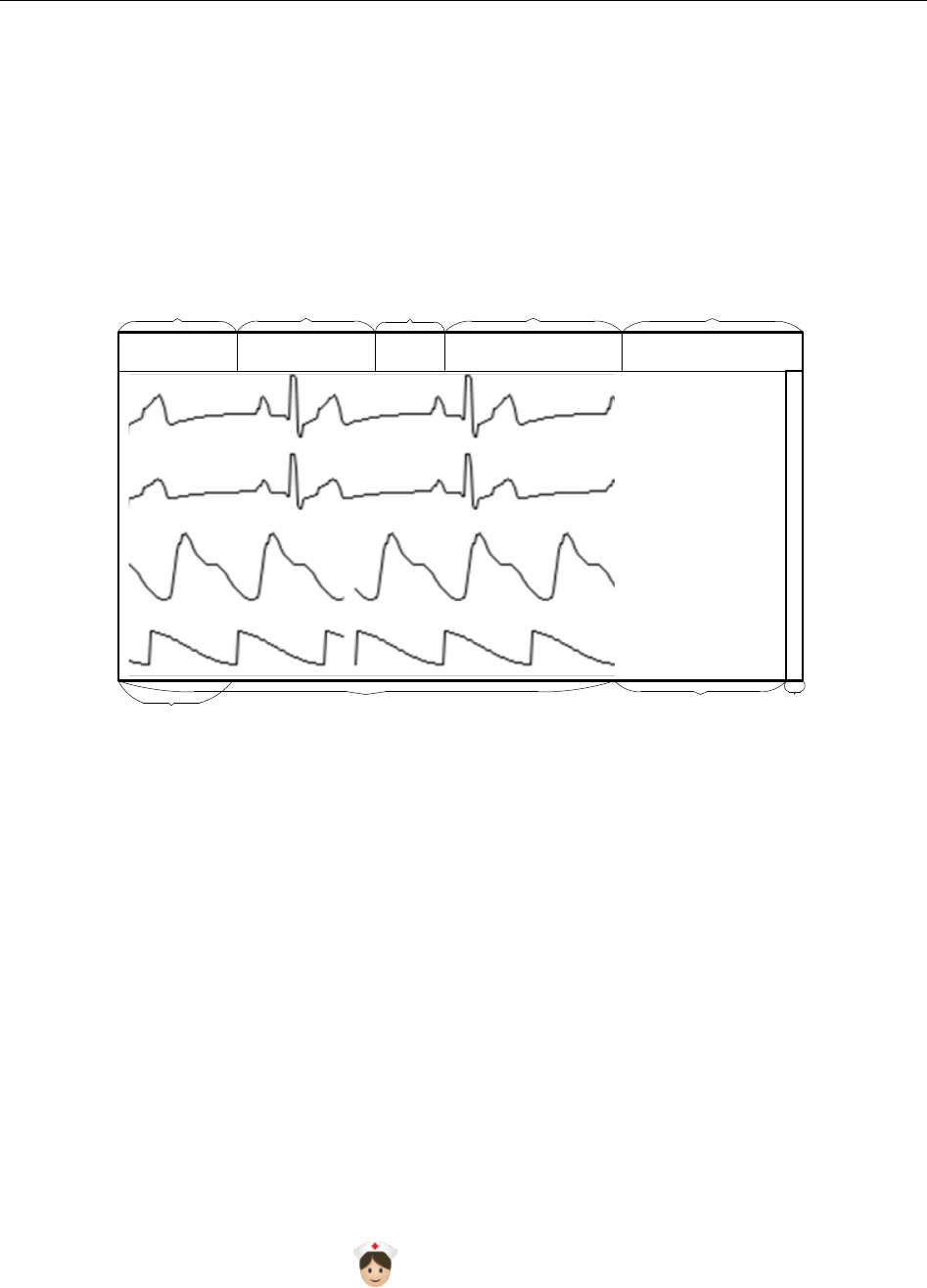
Telemetry Transmitter User Manual Viewing Single Bed
Chapter 7 Viewing Single Bed
The contents related to this chapter are all operated on MFM-CMS.
7.1 Display of Single Bed
The Single Bed View sub-window (shown as Figure 7-1) will be displayed by default when you
access the auxiliary screen.
xxx
xxx
xxx
xxx
60
99
36.5
40
xx xx
xx xx
xx xx
xx xx
1
68
25
xxx xxx xxx
xx
xx
xx
xx
xx
xx
xx
xx
4
79
xxx
3
xxx
Figure 7-1 Single Bed View Sub-Window
1: Patient information area 2: Toolbar 3: Indicator area
4: Technical alarm area/ Prompts area 5: Physiological alarm area 6: Short trend area
7: Waveform area 8: Parameter area 9: Scroll bar
Patient information area: It displays the bed No., patient name, gender, patient type, and
telemetry transmitter name.
You can perform the following functions via the toolbar:
– Freezing or unfreezing the waveforms displayed in the Single Bed View sub-window.
– Real-time printing (refer to Section 6.6 Real-Time Printing).
– Display setup: choosing the multi-lead waveform of ECG to be hided or shown (refer to
Section 7.2 Hiding/Showing Multi-Lead Waveform); setting the short trend display to on
or off; choosing the OxyCRG window to be opened or closed.
Indicator area: It displays indicators indicating the state of the telemetry transmitters (refer to
Table 6-). Nurse Call indicator will also be displayed here once the patient presses the
nurse call button on the telemetry device.
Technical alarm area/ Prompts area: It displays technical alarm messages consistent with the
messages displayed in the patient sector. The mouse operation here of technical alarm is the
- 42 -
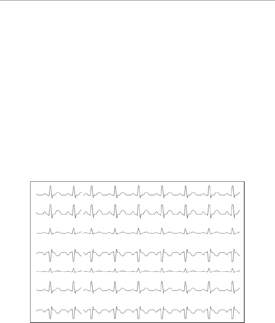
Telemetry Transmitter User Manual Viewing Single Bed
same as the one in patient sector (refer to Section 6.2 Networked Monitoring Display).
Physiological alarm area: It displays physiological alarm messages consistent with the
messages displayed in the patient sector. The mouse operation here of physiological alarm is
the same as the one in patient sector (refer to Section 6.2 Networked Monitoring Display).
Short trend area: When the short trend display is on, the short trend will be displayed in this
area. When the short trend display is off, waveforms will be displayed in this area.
Waveform area: It displays all waveforms from the networked telemetry transmitter.
Parameter area: It displays all parameters from the networked telemetry transmitter.
Scroll bar: You can drag the scroll bar to view more waveforms and parameters in this
window.
7.2 Hiding/Showing Multi-Lead Waveform
Choose View Selection > Multi-lead on the toolbar in the Single Bed View sub-window. The
waveform area can display multi-lead waveforms for ECG (shown as Figure 7-2). Choose View
Selection > Multi-lead again, and the multi-lead waveform display for ECG will become
unavailable.
xxx
xxx
xxx
xxx
xxx
xxx
xxx
Figure 7-2 Multi-Lead Waveforms for ECG
7.3 Short Trend Review
After entering the single bed view interface, choose View Selection > Trend Screen on the
toolbar and the short trend will be displayed on the left of the interface. Click short trend area and
a dialog box of short trend settings will pop up. You can set the display mode of the short trend
with the optional items in Param Select and Interval. You may select the desired parameters
needed to be displayed from the drop-down list of Param Select. Also, you can set the interval of
the short trend by choosing from 1h, 2h, 4h, 8h and 12h in the drop-down list of Interval.
- 43 -

Telemetry Transmitter User Manual Viewing Single Bed
7.4 OxyCRG
In the Single Bed View window, choose View Selection > OxyCRG on the toolbar, and the
OxyCRG window will be open. You can switch the display between respiratory rate and
respiratory waveform by clicking RR and RESP. You can also set the interval of the OxyCRG to
1 minute, 2 minutes or 4 minutes.
7.5 Freeze
You can freeze the waveform displayed in this window by choosing Freeze on the toolbar and
unfreeze the waveform by choosing Unfreeze.
The display of freezing waveform in the Single Bed View sub-window is consistent with the one
in the patient sector. Refer to Section 6.5 Freeze for more information.
- 44 -
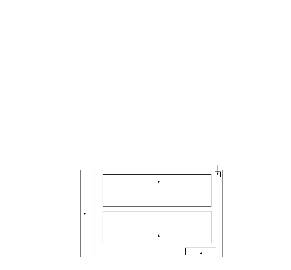
Telemetry Transmitter User Manual Setting Telemetry Transmitters via MFM-CMS
Chapter 8 Setting Telemetry Transmitters via MFM-CMS
The contents related to this chapter are all operated on MFM-CMS.
8.1 Changing Patient Information
Refer to Section 5.2 Changing Patient Information for more information.
8.2 Setting Parameters
You can open the parameter setup window by two methods:
Method 1: Choose Monitor Parameter Setup in the patient sector.
Method 2: Select the parameter area in the single bed interface, and click on the chosen parameter
area.
1
2
3 4
5
Figure 8-1 The Layout of the Parameter Setup Window
1: Physiological parameter list; 2: Alarm display and configuration list;
3: Physiological parameter attribute and configuration; 4: Update Monitor button;
5: Button for closing the window
The layout of the parameter setup window is shown as Figure 8-1.
The physiological parameter list shows all the available physiological parameter module of the
networked telemetry transmitter. Choose a parameter, the relevant alarm settings and parameter
attribute will be respectively displayed in Area 2 and Area 3. You can configure the alarm settings
(including alarm level, alarm switch, alarm upper and lower limits) and modify parameter
attributes, after which you click Update Monitor to update the relevant settings of the telemetry
transmitter.
Clicking button 5 can close parameter setup window.
- 45 -

Telemetry Transmitter User Manual Setting Telemetry Transmitters via MFM-CMS
8.2.1 Parameters Alarm Setting
You can configure the alarm setting via the alarm display and configuration list on the parameter
setup window. You can configure the alarm switch, alarm level, alarm upper and lower limits.
The operation steps are shown as follows:
1. Choose a parameter from the physiological parameter list.
2. Configure the alarm settings in the alarm display and configuration list.
3. Click Update Monitor to bring the configuration into effect.
WARNING
1 Prior to monitoring, make sure that the alarm limit settings are appropriate for your
patient.
2 When the alarm is set to OFF, MFM-CMS won’t give an alarm even if an alarm
occurs. In order to avoid endangering the patient’s life, the user should use this
function cautiously.
3 Setting alarm limits to extreme values may cause the alarm system to become
ineffective. It is recommended to use the default settings.
8.2.2 Physiological Parameter Attribute and Configuration
For the telemetry transmitters, the MFM-CMS can display the parameter attributes of ECG, SpO2
and RESP whose settings can also be configured.
You can configure the following items for the parameter ECG of the telemetry devices: lead type,
Calc. lead, pace, alarm source, filter, ECG Gain, ST Analysis, ARR Analysis, Smart LeadOff,
Hum Filter and electrode setup.
You can configure the following items for the parameter SpO2 of the telemetry devices:
Sensitivity and Alarm Source (when choose PR).
You can configure the following items for the parameter RESP of the telemetry devices: RESP
Lead, Apnea Time and ECG Gain.
NOTE:
Telemetry transmitter reads leads style automatically. Electrode setup is only applicable
to ECG lead off alarms for telemetry transmitter.
- 46 -

Telemetry Transmitter User Manual Review
Chapter 9 Review
The contents related to this chapter are all operated on MFM-CMS.
Via the MFM-CMS, you can review the history data of patients, which includes the list
containing all patients, patient management, trend, alarm and wave. By clicking on the review
button in quick control area of main screen, you can enter the review interface.
9.1 Patient List
Clicking review button in quick control area of main screen and you will access the review
interface. It displays the Patient List by default. By respectively selecting the items from the
drop-down list shown at the top left corner, you can review the list of patients who have been
admitted by the MFM-CMS, the list of patients who have been discharged, and the list of patients
saved in the backup database.
You can select a patient from the list and click the Patient Mgmt tab to review detailed
information of this patient. Also, you can double click the patient name in the list to open the
patient management window. Choose Trend Review, Alarm Review and Wave Review, you
can review relevant monitoring data of the patient.
There is a query column and a small inverted triangular black indicator on the top right corner of
review interface. To search a patient’s information, click the inverted triangular black indicator
and choose one of items (such as MRN, patient’s first name, patient’s family name and doctor)
from the drop-down list. Input patient’s information related with the items and click on Query. If
the patient information is saved, the corresponding information is displayed on the screen.
9.1.1 Patient Review
By default, the Patient List displays the patients who have been admitted by the MFM-CMS
after entering the review interface. And also, the default items from the drop-down lists shown at
the top left corner will be Online Database Source and Patient Review.
Select a patient and click Discharge, and this patient will be discharged. The discharged patients
will be transferred to the History Patient Review list. Refer to Section 9.1.2 History Patient
Review for more information.
9.1.2 History Patient Review
Respectively select Online Database Source and History Patient Review from the drop-down
lists shown at the top left corner, and you can review the list of patients who have been
discharged.
To delete patients, please: Select a patient > click Delete > input password ABC in popup
window > click OK to finish deleting. The patients deleted will be completely deleted from the
MFM-CMS.
- 47 -

Telemetry Transmitter User Manual Review
CAUTION
If you delete a patient from the History Patient Review list, his or her data will be
completely removed from the system.
9.1.3 Backup Patient Review
Select Offline Database Source from the drop-down list shown at the top left corner, and you
can review the backup patient data. Refer to Section 0 Reviewing Backup Database for more
information.
9.2 Wave Review
The MFM-CMS can review the change process of the physiological waveform of one patient in
the latest 96 hours. And the system can provide 96-hour waveform review.
To use 96-hour waveform review, please click on Main Screen > Review > Wave Review or
access the auxiliary screen and choose Wave Review. On this screen, you can:
Review normal waveforms or compressed waveforms
Set wave speed
Select waveform
Refresh waveform
Print
9.2.1 Reviewing Normal Waveforms
Normal waveform review is available to all parameter waveforms. In the normal waveform
review window, the waveform is displayed with the same altitude and speed of the real-time
waveform.
You can select Show parameters/Hide parameters. If you select Show parameters, the related
parameter value will also be displayed accompanying the waveform you choose.
In this window, waveforms can also be presented by automatically sliding forward.
9.2.2 Reviewing Compressed Waveforms
Compressed waveform review is only available to ECG waveforms. In the compressed waveform
review window, the altitude of the ECG waveform will be compressed so that you can review the
waveform containing longer time of data.
- 48 -

Telemetry Transmitter User Manual Review
9.2.3 Setting Wave Speed
By clicking on the Sweep button, you can set the width of waveforms displayed in the waveform
area. Available options are 6.25 mm/s, 12.5 mm/s, 25 mm/s and 50 mm/s. Changing wave speed
will affect the time length of the waveform area.
9.2.4 Refreshing Waveform
Waveform will not update automatically. Therefore, if you want to view up-to-date waveform,
you have to refresh them manually. Clicking on the Refresh button will refresh the waveform.
9.2.5 Selecting Waveform
Click on the Select Wave button, and a list of available waveforms will be shown. By default, all
waveforms are selected. You can deselect a waveform by ticking its check box.
NOTE:
The 96-hour full disclosure waveform storage will occupy a lot of hard disc. Therefore, the
user shall be cautious to add additional waveform to the selecting waveform setup.
9.2.6 Print
To print the waveform displayed on the current screen, please select Print on the screen to print it
by the laser printer.
9.3 Alarm Review
Alarm table and waveform will be generated when the MFM-CMS makes physiological alarm
notification. Alarm review helps the clinician observe the details of the monitoring information.
Alarm information can be stored by the user and thus become important alarm event. An alarm
strip in the alarm review is a 16-second waveform.
NOTE:
If telemetry transmitter or MFM-CMS switches off, the alarm information stored by
MFM-CMS will not be deleted. A maximum of 720 alarm information can be stored. If the
storage space is full and there are new alarms occur, the earliest alarm information will
disappear.
9.3.1 Locking and Unlocking Alarm Information
When the user thinks that an alarm is very important, he/she can save it by locking the alarm
information with a symbol √ on the alarm review interface. The symbol √ will appear to its right
on this interface when the alarm is locked. The locked alarm cannot be deleted automatically. You
can click on the symbol √ to unlock the locked alarm, the symbol √ will disappear.
- 49 -

Telemetry Transmitter User Manual Review
9.3.2 Printing Alarm Information
If the user wants to print alarm table, he/ she can click on Print on the interface to print it by a
laser printer.
NOTE:
1 The important alarm events can be deleted but not automatically .The non-important
alarm events can be automatically replaced by new alarm events when they have
accumulated to a certain amount.
2 The alarm stripe displays the physiological waveform at 25mm/s when an alarm
takes place.
9.3.3 Sequencing the Alarm List
You can sequence all alarms ascendingly or descendingly by clicking on the heading of any
column:
Alarm Time: Clicking on it will sequence all alarms ascendingly or descendingly by
time.
Alarm Information: Clicking on it will sequence all alarms ascendingly or
descendingly by parameter.
Alarm Level: Clicking on it will sequence all alarms ascendingly or descendingly by
level.
At the same time, one of the following symbols will appear on the bottom of the heading:
The symbol ▲ indicates ascending sequence, and
The symbol ▼ indicates descending sequence.
9.3.4 Annotating Alarm
You can add notes to illuminate an alarm. To annotate an alarm, select a certain alarm stripe and
you will see the title Alarm Note on the bottom of the alarm review interface. Move the cursor
1cm left to the title Alarm Note and a pop-up input box in which you can input detailed
information for the alarm will appear. After you complete your notes, move the cursor out of the
area of the input box, and MFM-CMS will automatically save the input information.
NOTE:
Input characters are limited to 256.
9.3.5 Filtering Alarm Events
You can filter alarm events by selecting or clearing the check boxes before the items in the
Alarm Level list and in the Param Select list. The Alarm Review window will only display the
alarm events whose alarm level /levels has/have be selected and the alarm events of selected
parameters.
- 50 -

Telemetry Transmitter User Manual Review
9.4 Trend Review
Choose Main Screen > Review > Trend Review or choose Trend Review on the auxiliary
screen, and you will enter the trend review interface, through which you can store and review up
to 240 hours of trend data. Change of trends can be observed through trend table and trend graph.
On this interface, you can:
set the resolution
view parameters selectively
refresh the data
print
Time Setup, can set the starting and ending time for review.
9.4.1 Setting Resolution
You can select a time period as the resolution for viewing the graph and table as required.
Options are 1s, 5s, 1m, 5m, 15m, 30m and 60m. To change the resolution, select Resolution
Setting on the interface and select the desired option from the list.
9.4.2 Viewing Parameters selectively
In the parameter list of Param Select, you can select modules or parameters by ticking their
check boxes as required. Only the selected parameters are displayed in the graph or table.
When a parameter module is selected or unselected, all of its parameters will be selected or
unselected accordingly.
9.4.3 Refreshing Data
Trend data will not update automatically. Therefore, if you want to view up-to-date trend data,
you have to refresh them manually. Click on the Refresh button to refresh the data to up-to date.
After refreshing them, the status selected and order of parameters remain unchanged.
9.4.4 Printing Trend Review
Clicking on Trend Review > Print > Print Trend Table/ Print Trend Graph, you can print the
trend table or the trend graph. By default, the system will print the latest data.
9.4.5 Selecting Trend Table, Trend Graph
Select Trend table to review the trend table only. Select Trend Graph to review the trend graph
only. Select Trend Table, Trend Graph to review the trend table and trend graph at the same
time.
- 51 -

Telemetry Transmitter User Manual System Setup
Chapter 10 System Setup
The contents related to this chapter are all operated on MFM-CMS.
The System Setup function is used to modify the display information at the patient section
according to the real requirements. By using this function, you can observe the waveform,
parameter, and the parameter list as your desire. There are Common Setup, User Maintain, and
Factory Maintain to be set.
10.1 Common Setup
It is mainly used to make some conventional monitoring settings, such as Param Unit Setup,
Color Settings, Display Setup, Help and Telemetry Module Switch Setup.
10.1.1 Color Setup
The user can change the display color of all parameters and the other information of the
parameter is displayed as the same color. And the information includes waveform name, gain and
filter, real-time value (upper limit and lower limit), review waveform and so on. To change the
color of the parameter:
1. Please select Main Screen > System Setup > Common Setup > Color Setup. Click on the
Param Select to choose desired parameter, then choose desired color from the left color area
or input desired RGB values of red, green, blue directly.
2. After this, click on OK to confirm.
After setting, the color displayed on Color Setup colomn is the successfully chosen color. The
color on Initial Color colomn is set by default.
To get the default color, choose desired parameter from Param Select and click Default Settings,
and then click OK to confirm.
10.1.2 Display Setup
The user can set the bed numbers to be viewed on the screen. To change the display to be viewed,
please select Main Screen > System Setup > Common Setup > Display Setup and choose the
desired bed number 3, 4, 6, 8, 10, 12, 14, 16, 32, 64 from the drop-down list of display bed.
NOTE:
Two screens are needed if you want to simultaneously display the information of 64
telemetry transmitters.
10.1.3 Telemetry Module Switch Setup
You can configure the module switch setting of the telemetry transmitter via the MFM-CMS.
Choose Main Screen > System Setup > Common Setup > Telemetry Module Switch Setup.
From the Telemetry Device List on the left of the setup window, choose the telemetry transmitter
- 52 -

Telemetry Transmitter User Manual System Setup
for which you want to configure the module switch setting. On the right of the setup window,
configure the setting as required.
10.1.4 Help
Help information is available on this interface.
10.2 User Maintain
To access the settings interface of user maintain, you have to input a user password. The default
password is ABC.
10.2.1 Telemetry Transmitter Batch Settings
You can configure the alarm limit, alarm switch and alarm level for a group of telemetry
transmitters. You need to choose a patient type from Adult or Pediat before you configure the
alarm settings in Templet of Alarm Limit Adjusting Range. Choose the telemetry transmitters
needing to be configured in the right pane in which you may see a list of telemetry transmitters,
and click Config. The configuration in the left templet pane will be applied to the chosen
telemetry transmitters.
Besides, from the right pane, you can choose a telemetry transmitter whose alarm settings will
serve as the source of batch settings for other telemetry transmitters. Select one telemetry
transmitter in the right pane and click Obtain Monitor Configuration to obtain its parameter
alarm settings. The obtained configuration will be displayed in the left templet pane. Choose the
telemetry transmitters needing to be configured in the right pane and click Config to complete
batch settings.
NOTE:
1 If the patient type set in Templet of Alarm Limit Adjusting Range is different from
the one set on the telemetry transmitter to be configured, the system may fail to set
the configuration for telemetry transmitter.
2 The prompt message Success only indicates success in setting the configuration for
current activated parameters on the telemetry transmitter.
10.2.2 Telemetry Alarm Latch Setup
You can configure the alarm latching setting of the telemetry transmitter via the MFM-CMS.
Choose Main Screen > System Setup > User Maintain > Telemetry Alarm Latch Setup.
From the Telemetry Device List on the left of the setup window, choose the telemetry transmitter
for which you want to configure the latching setting. On the right of the setup window, configure
the setting as required.
The latching alarm setting of the telemetry transmitter is off by default. For telemetry transmitter
which has been offline and then online and in which the patient is admitted again, the latching
alarm configuration remains the same as the last configuration used by the telemetry transmitter.
- 53 -

Telemetry Transmitter User Manual System Setup
To clear the alarms latched, please choose Alarm Reset from the menu in the patient sector.
Refer to 6.3 Menu in the Patient Sector for details.
10.2.3 Date/Time Setup
To change date and time for MFM-CMS, please refer to 3.8 Setting Date and Time.
10.2.4 MFM-CMS System Alarm Setup
You can configure the alarm setting for the MFM-CMS.
You can set the duration for the audio pause to 1 minute, 2 minute or 3 minute. By click the
Audio Pause button on the main screen, you can activate or deactivate the audio pause function.
You can enable/disable alarm mute function by selecting/ deselecting the Alarm Mute check box.
When Alarm Mute is not selected, the alarm Mute is disabled. When Alarm Mute is selected,
the alarm mute function is enabled. The icon is displayed at the top area of the screen.
You can set alarm sound intervals by choosing the desired intervals from the drop-down list of
High Alarm Interval (s), Med Alarm Interval (s) and Low Alarm Interval(s).
NOTE:
Once a new alarm occurs, the system will neglect the existing settings of Alarm Mute and
generate a new alarm.
10.2.5 Changing Language
To change the display language, please select Main Screen > System Setup > User Maintain,
and input the correct password. Select Language Setup and select the desired language from the
drop-down list.
NOTE:
The user must restart MFM-CMS to make the change effective.
10.2.6 HL7
Users can set the interval for HL7 data to be sent and set the format of HL7 packing data sent by
MFM-CMS. The interval can be set to 1 to 120 minutes. HL7 data is sent in the format of HL7
Lower Level Protocol by default. If the item XML is selected, the data sent by MFM-CMS will
be packed in the XML format.
NOTE:
HL7 data is sent via the port 9100 by default.
- 54 -

Telemetry Transmitter User Manual System Setup
10.2.7 Database Maintain
Refer to Section 14.1 Database Backup for more information about database backup.
10.2.8 Other Setups
On this interface, you can:
Set Hospital Info. and Department. The hospital information and department will be
displayed at the top left corner on the main screen.
Choose to display or conceal the grid in the View window by selecting or clearing the check
box of Display Grid on View.
Set Electrode Setup to AHA or IEC. Electrode setup is only applicable to ECG lead off
alarms for telemetry transmitter.
Return to Windows.
Switch off the system.
10.2.9 User Password Setting
To modify the password, enter the old password in the Old Password field and a new one in the
New Password field, after which you have to Confirm new password to complete the
modification.
NOTE:
If you forget the password, please contact the technical representative of EDAN.
10.2.10 About
It offers information about the software compiled time and software version.
- 55 -

Telemetry Transmitter User Manual Alarm Management
Chapter 11 Alarm Management
The contents related to this chapter are all operated on MFM-CMS.
11.1 Overview
Alarms, triggered by a physiological sign that appears abnormal or by technical problems of the
telemetry transmitter, are sent to the MFM-CMS by the telemetry transmitters and then indicated
to the users by the MFM-CMS. Alarms coming from the telemetry transmitters are displayed in
the patient sectors and in the single bed view window.
The alarm and prompts coming from the MFM-CMS system are displayed in the system
information area on the upper screen.
WARNING
A potential hazard can exist if different alarm presets are used for the same or similar
equipment in any single area, e.g. an intensive care unit or cardiac operating room.
NOTE:
The alarm signal will be delayed for no more than 5 seconds.
11.1.1 Physiological Alarms
If one or several physiological parameters of the currently monitored patient exceed the
predefined alarm limit, the telemetry transmitter will give an alarm, and this type of alarm is
called physiological alarms. It includes parameter alarm and arrhythmia alarm. About the detailed
alarm information, please refer to the Section Chapter 12 Alarm Information.
Physiological information alarm arouses the doctors’ attention by means of visual and audible
methods specified in harmonized international standard. Visual method is realized basically by
the way of lightening or flicking of the color light. Audible method is realized by the sound for
different levels.
Physiological alarms are implemented by alarm limits, which define a range in which a certain
physiological parameter is considered to be in the normal status. When a parameter value is
beyond the range, the system will consider it to be in an abnormal status and consequently give
an alarm.
11.1.2 Technical Alarms
If one or several technical status of the device is in abnormal status, the telemetry transmitter will
send an alarm to MFM-CMS. And this type of alarm is called technical alarms. Technical alarms
can’t be disabled. Technical alarms of telemetry transmitter refer to alarms other than
physiological alarms, including hardware failure, communication error, lead off, etc. About the
detailed alarm information, please refer to Section Chapter 12 Alarm Information.
- 56 -

Telemetry Transmitter User Manual Alarm Management
For these technical alarms, the system indicates by four different types of audible and visual
prompts.
When a group of technical alarms (for example, transducer falls off) produced by telemetry
transmitters, a piece of alarm prompt information in scrolling mode will appear on the main
screen of MFM-CMS. In addition, the MFM-CMS will sound corresponding alarm (high,
medium or low level alarm).
11.1.3 Prompts
Telemetry transmitter can send the character indication of monitoring process or other functions
to MFM-CMS. This character, with black background, white font and with no alarm sound, is
called prompts. The About the detailed alarm information, please refer to Section Chapter 12
Alarm Information.
11.2 Alarm Levels
Alarm level reflects the severity of an alarm. The alarms from telemetry transmitters are divided
into three groups regarding the alarm levels.
1. High level alarms
A high level alarm intensively warns the operator of a high priority alarm condition which
requires immediate operator response. Failure to respond to the cause of the alarm condition is
likely to result in death or irreversible injury of the patient.
2. Medium level alarms
A medium level alarm warns the operator of a medium priority alarm condition which requires
prompt operator response. Failure to respond to the cause of the alarm condition is likely to result
in reversible injury of the patient.
3. Low level alarms
A low level alarm reminds the operator of a low priority alarm condition which requires response.
And the response time for a low priority alarm condition can be greater than that for a medium
priority alarm condition. Failure to respond to the cause of the alarm condition is likely to result
in discomfort or reversible minor injury of the patient.
11.3 Parameters Alarm Setting
Refer to 8.2.1 Parameters Alarm Setting for Information related to parameters alarm setting.
11.4 Alarm Mute
For information about how to set alarm mute, refer to Section 10.2.4 MFM-CMS System Alarm
Setup. Alarm mute means that when an alarm occurs, the system will not give an alarm sound but
only maintain a visual prompt.
- 57 -

Telemetry Transmitter User Manual Alarm Management
NOTE:
Once a new alarm occurs, the system will neglect the existing settings of Alarm Mute and
generate a new alarm.
11.5 Audio Pause
Audio Pause means that during a period of time, when an alarm occurs, the system will not give
alarm announcement. The duration setting is introduced in Section 10.2.4 MFM-CMS System
Alarm Setup. By click the Audio Pause button on the main screen, you can activate or deactivate
the audio pause function.
When the duration of alarm pause has lasted for the preset-time, the system will stop the status of
alarm pause and resume normal alarm automatically.
NOTE:
Once a new alarm occurs, the system will neglect the existing settings of Alarm Voice
Pause and generate a new alarm.
11.6 Alarm Prompt/Response
Alarm information can be prompted by means of visual and audible methods. Because the alarm
information is very important and timely response to the alarm information is highly required, the
MFM-CMS provides the following methods to indicate to the user the occurrence of the alarm.
The alarm message will be displayed in the technical area or physiological area of the patient
sector and of the single bed view window.
High level alarm: displayed with red background
Medium level alarm: displayed with yellow background
Low level alarm: displayed with yellow background
An asterisk or more will be displayed before the physiological alarm message to indicate the
alarm level.
High level alarm: ***
Medium level alarm: **
Low level alarm: *
For limit alarms of the parameter, the relevant parameter value and alarm limit value will be
respectively displayed with the color alternating between the parameter color and the alarm
color.
When physiological alarm exceeds the alarm limit, the icons for parameters exceeding the
alarm limits will be displayed in parameter value area. The icon is for high level alarm; Icon
is for medium and low level alarm.
- 58 -

Telemetry Transmitter User Manual Alarm Management
Alarm sound
If the system mute, alarm mute or alarm pause setup is deactivated, the system will warn the user
about the alarm with the alarm sound. The sound pressure range for audible alarm signals is from
45 dB to 85 dB.
The alarm sound can be:
High level alarm: sound "DO-DO-DO DO-DO DO-DO-DO DO-DO"; The adjustable
range of alarm sound interval is from 6 to 15 seconds.
Medium level alarm: sound "DO-DO-DO"; The adjustable range of alarm sound interval is
from 6 to 30 seconds.
Low level alarm: sound "DO- ". The adjustable range of alarm sound interval is from 15 to 30
seconds.
WARNING
1 Do not rely exclusively on the audible alarm system for patient monitoring.
Adjustment of alarm volume to a low level or off during patient monitoring may result
in patient danger. Please remember that the most reliable method of patient
monitoring combines close personal surveillance with correct operation of monitoring
equipment.
2 Ensure the volume is properly set up. When the sound pressure of audible alarm is
below or equivalent to the ambient noise, it may be difficult for the operator to
distinguish the audible alarm.
11.7 Testing Alarms
When you switch the MFM-CMS on, a self-test is started. Refer to 4.2.2 Switching on/off the
MFM-CMS.
The physiological alarms, technical alarms and prompts from telemetry transmitter are displayed
on MFM-CMS. Before monitoring, user should perform the measurement on yourself or use a
simulator to check the follows:
System information area can normally display technical alarms and prompts of MFM-CMS
system;
Patient sector and single bed view can normally display physiological alarms, technical
alarms and prompts of telemetry transmitter;
Alarm sound can be heard clearly.
The correct checking above indicates that the visible and audible alarm are functioning correctly. For
further alarm tests, please adjust the alarm limits to check whether the alarm response is correct.
- 59 -

Telemetry Transmitter User Manual Alarm Management
11.8 Alarms for Networking Status
When telemetry transmitter is online or offline, the system will indicate it with a sound of “du”.
If telemetry transmitter is offline without being discharged, the system will indicate it with
medium level alarm sound whose interval is same with interval of medium level alarm sound for
parameters alarm.
- 60 -

Telemetry Transmitter User Manual Alarm Information
Chapter 12 Alarm Information
All alarm information will be displayed on MFM-CMS.
WARNING
During monitoring, the physiological alarms including ASYSTOLE, VFIB/VTAC, RESP
APNEA and SpO2 No Pulse are preset to be on and cannot be turned off.
12.1 Physiological Alarm Information
Message Cause Alarm level
HR High HR measuring value is above the upper alarm limit. User-selectable
HR Low HR measuring value is below the lower alarm limit. User-selectable
ST-X High ST measuring value is above the upper alarm limit. (X
stands for I, II, III, aVR, aVL, aVF, V) User-selectable
ST-X Low
ST measuring value is below the lower alarm limit.(X
stands for I, II, III, aVR, aVL, aVF, V) User-selectable
PVCs High PVCs measuring value is above the upper alarm limit. User-selectable
ASYSTOLE No QRS is detected for 4 consecutive seconds High
(user-unselectable)
VFIB/VTAC
4 consecutive seconds' fibrillation wave occurs, or
each RR interval for 5 consecutive ventricular beats is
less than 600 ms.
High
(user-unselectable)
VT>2 3 ≤ the number of consecutive PVCs < 5 User-selectable
COUPLET 2 consecutive PVCs User-selectable
BIGEMINY
A dominant rhythm of N, V, N, V (N =
supraventricular beat, V = ventricular
beat) was
detected.
User-selectable
TRIGEMINY A dominant rhythm of N, N, V, N, N,V User-selectable
R ON T
A type of single PVC under the condition that
HR<100,R-
R interval is less than 1/3 the average
interval, followed by a compensating pause of 1.25X
the average R-R interval (the next R wave advances
onto the previous T wave).
User-selectable
PVC Single PVC detected in normal heartbeats. User-selectable
TACHY
Adult: RR interval for 5 consecutive QRS complex ≤
0.5s.
Pediatric: RR interval for 5 consecutive QRS complex
≤ 0.375s.
User-selectable
- 61 -

Telemetry Transmitter User Manual Alarm Information
Message Cause Alarm level
BRADY
Adult: RR interval for 5 consecutive QRS complex ≥
1.5s.
Pediatric: RR interval for 5 consecutive QRS complex
≥ 1s.
User-selectable
MISSED BEATS
If HR < 120 bpm, no beats are detected for 1.75 times
average RR interval; or if HR ≥ 120 bpm, no beats are
detected for one second.
User-selectable
IRR
Consistently irregular heart rhythm
User-selectable
PNC (with
pacemaker)
PACE NOT CAPTURE: no QRS complex detected in
300ms after a pace pulse. User-selectable
PNP (with
pacemaker)
PACER NOT PACED: no pace pulse detected in 1.75
times RR interval after a QRS complex. User-selectable
VBRADY
VENTRICULAR BRADYCARDIA: Each RR
interval for 5 consecutive ventricular beats > 1000 ms. User-selectable
VENT
VENTRICULAR RHYTHM: Each RR interval for 5
consecutive ventricular beats ranges from 600 ms to
1000 ms.
User-selectable
RESP APNEA RESP cannot be measured within the set apnea alarm
delay time.
High
(user-unselectable)
RR High RR measuring value is above upper alarm limit. User-selectable
RR Low RR measuring value is below lower alarm limit. User-selectable
SpO2 High SpO2 measuring value is above upper alarm limit. User-selectable
SpO2 Low SpO2 measuring value is below lower alarm limit. User-selectable
SpO2 No Pulse The signal of the measurement site is too weak, so the
telemetry transmitter can’t detect the pulse signal.
High
(user-unselectable)
PR High PR measuring value is above upper alarm limit. User-selectable
PR Low PR measuring value is below lower alarm limit. User-selectable
- 62 -

Telemetry Transmitter User Manual Alarm Information
12.2 Technical Alarm Information
NOTE:
The ECG alarm information listed in the below table describes the lead names in
America. For the corresponding lead names in Europe, please refer to the section
Installing Electrodes.
Message Cause Alarm Level Action Taken
ECG Lead Off
1) The drive electrode or
more than one ECG limb
electrode falls off the skin;
2) ECG cables fall off the
telemetry transmitter.
Low
Make sure that all
electrodes, leads and
patient cables are
properly connected.
ECG LL Lead Off
ECG electrode LL falls off
the skin or the ECG cable
LL falls off the telemetry
transmitter.
Low
Make sure that all
electrodes, leads and
patient cables are
properly connected.
ECG LA Lead Off
ECG electrode LA falls off
the skin or the ECG cable
LA falls off the telemetry
transmitter.
Low
Make sure that all
electrodes, leads and
patient cables are
properly connected.
ECG RA Lead Off
ECG electrode RA falls off
the skin or the ECG cable
RA falls off the telemetry
transmitter.
Low
Make sure that all
electrodes, leads and
patient cables are
properly connected.
ECG V Lead Off
ECG electrode V falls off
the skin or the ECG cable V
falls off the telemetry
transmitter.
Low
Make sure that all
electrodes, leads and
patient cables are
properly connected.
ECG Signal Exceeded ECG measuring signal is
beyond measuring range. Low
Check lead
connection and
patient condition
ECG Noise
ECG measuring signal is
greatly interrupted. Low
Check lead
connection and
patient condition
- 63 -

Telemetry Transmitter User Manual Alarm Information
Message Cause Alarm Level Action Taken
RESP Cardiac Artifact
No RESP waveform can be
detected due to apnea or
shallow breathing of the
patient.
High
Check whether the
patient is breathing
normally. Take
measures to help the
patient breathe
normally when
necessary. If the
patient is breathing
normally, try to
adjust the electrode
position on the
patient in order to
reduce the
interference of
cardiogenic artifact.
RESP Noise RR cannot be measured due
to patient movement. Low
Check whether the
RESP leads are well
connected. Keep the
patient calm for
better monitoring.
RR Exceed RR measuring value is out
of the measure range. Medium
Check whether
interference to the
respiratory signal
exists. And check
whether the patient is
breathing normally;
breathing too rapidly
or too slowly may
endanger patient’s
life.
SpO2 Sensor Off
SpO2
sensor may be
disconnected from the
patient or the telemetry
transmitter.
Low
Make sure the sensor
is well connected to
the patient’s finger
or other parts.
SpO2 No Sensor
SpO2
sensor was not
connected well or connected
to the telemetry transmitter,
or the connection is loose.
Low
Make sure the
telemetry transmitter
and sensor are well
connected and
reconnect the sensor.
- 64 -

Telemetry Transmitter User Manual Alarm Information
Message Cause Alarm Level Action Taken
SpO2 Low Perfusion
The pulse signal is too
weak or the perfusion of
the measurement site is too
low. The value displayed
may not be correct.
Low
Reconnect the SpO2
sensor and change
the measurement
site. If problem
exists, please notify
biomedical engineer
or manufacturer’s
service staff.
SpO2 Noisy Signal
There is interference with
SpO2 measurement signals
and the waveform is
abnormal.
Low
Check the condition
of patient and avoid
patient movement;
make sure the cable
is well connected.
SpO2 Light
Interference
Ambient light around the
sensor is too strong. Low
Reduce interference
of the ambient light
and avoid sensor’s
exposure to strong
light.
Battery Low Battery Low High
Change the batteries
or
charge the
batteries.
No si
gnal for
telemetry transmitter
Telemetry transmitter didn’t
connect to MFM-CMS. Medium
Check whether
network connection,
MFM-CMS and
wireless AP are work
normally, or contact
supplier.
Check the ECG
accessories
ECG cables have connected
to patient, and
the valid
authorized information for
ECG accessories
cannot be
detected.
Medium
Use the specified
ECG accessories.
- 65 -

Telemetry Transmitter User Manual Alarm Information
12.3 Prompts
Message Cause
ECG Arr Learning
The QRS template building required for
Arr. Analysis is in process.
SpO2 Search Pulse
SpO2
module is analyzing the patient
signal and searching for the pulse to
compute the saturation, when sensor is
connected with patient.
Weak Wi-Fi signal The status that iT20 Wi-Fi signal is lower
than level 1, means Wi-Fi signal is weak.
12.4 Adjustable Range of Alarm Limits
ECG alarm limits are listed as follows: unit (bpm)
Patient Type
ALM HI
ALM LO
HR
ADU
300
15
PED
350
15
ST analysis alarm limits are listed as follows: unit (mV)
ALM HI
ALM LO
ST
2.0
-2.0
PVCs alarm upper limits are listed as follows:
ALM HI
ALM LO
PVCs
10
0
RESP alarm limits are listed as follows: unit (rpm)
Patient Type
ALM HI
ALM LO
RESP
ADU
120
6
PED
150
6
- 66 -

Telemetry Transmitter User Manual Alarm Information
SpO2 alarm limits are listed as follows (unit %):
ALM HI
ALM LO
SpO
2
100
20
PR alarm limits is listed as follows: unit (bpm)
ALM HI
ALM LO
PR
300
30
- 67 -

Telemetry Transmitter User Manual Printing
Chapter 13 Printing
The contents related to this chapter are all operated on MFM-CMS.
13.1 Printing Report with a Printer
MFM-CMS can output the reports by equipped with a laser printer. HP LaserJet Series printers
are recommended. The laser printer working with the MFM-CMS is independent of the
mainframe. The printer has its independent power supply. It is connected to the mainframe via a
USB interface or a network (wired or wireless).
The laser printer generates the following types of printing:
Waveform review printing
Alarm wave printing
Alarm table printing
Trend graph printing
Trend table printing
Printing for drug calculation, hemodynamic calculation, oxygenation calculation, renal
function calculation and ventilation calculation
Patient information printing
NOTE:
MFM-CMS only supports printing on A4 paper.
13.2 Printing Preview/ Printing Settings
13.2.1 Printing Preview
Before the reports are printed, you can preview them on the screen. You will access the preview
interface after you select the function of printing. If a report consists of more than one page, you
may select a certain page to preview by turning to the page you want. Besides, you can adjust the
zoom setting by choosing a certain option from the drop-down list of the SIZE.
13.2.2 Printing Settings
Click on Print on the preview interface, and in the Print setup menu select the printer, the print
range and the number of copies in demand and then click on OK to confirm it.
13.3 Exporting the PDF File
MFM-CMS can export the PDF file by installing a PDF printer software. The software
PDFCreator is recommended. You can obtain the installation version of PDFCreator in the
MFM-CMS installation disk. Also, you may download it from the website
- 68 -

Telemetry Transmitter User Manual Printing
http://www.pdfforge.org/pdfcreator.
To export the PDF file, choose a PDF printer (for instance, PDFCreator) from the drop-down list
when you select the printers, and then confirm it by clicking on OK.
- 69 -

Telemetry Transmitter User Manual Database Management
Chapter 14 Database Management
The contents related to this chapter are all operated on MFM-CMS.
MFM-CMS provides database backup and review, which allows you to conveniently manage and
maintain data.
14.1 Database Backup
To backup database, please select Main Screen > System Setup > User Maintain, and input the
correct password. Select Database Maintain and click on the button Browse to choose a
directory for backup file storage. Then click on Backup Database to start database backup.
NOTE:
1 During database backup, MFM-CMS automatically stops its patient monitoring.
2 MFM-CMS will restart automatically after it completes database backup.
3 If the check box indicating “Empty local database after backup is completed” is
ticked, MFM-CMS will empty the local database after database backup is completed.
14.2 Reviewing Backup Database
MFM-CMS allows you to review the backup data at any time.
To review backup data, select Main Screen > Review > Patient List, and select the directory for
storing backup file from the drop-down list of Offline Database Source. For more information
about review, refer to Chapter 9 Review.
NOTE:
1 It takes about 3 to 10 seconds for MFM-CMS to load the backup data.
2 During reviewing backup data, discharging or deleting patients is unavailable.
- 70 -

Telemetry Transmitter User Manual Monitoring ECG
Chapter 15 Monitoring ECG
15.1 Overview
The electrocardiogram (ECG) measures the electrical activity of the heart and displays it on the
telemetry transmitter as a waveform and a numeric. This chapter also tells you about arrhythmia
monitoring and ST monitoring.
15.2 ECG Safety Information
WARNING
1 Only use the ECG leads supplied by the manufacturer when using telemetry
transmitter for ECG monitoring.
2 When connecting the cables and electrodes, make sure no conductive part is in
contact with the ground. Verify that all ECG electrodes, including neutral electrodes,
are securely attached to the patient but not the conductive part or ground.
3 Check every day whether there is skin irritation resulted from the ECG electrodes. If
yes, replace electrodes every 24 hours or change their sites.
4 Place the electrode carefully and ensure a good contact.
5 Check if the lead connection is correct before monitoring. If you unplug the ECG cable
from the socket, the screen will display the error message “ECG LEAD OFF” and the
audible alarm is activated.
6 If the ECG signal exceeds the measuring range, MFM-CMS will indicates it by a
message “ECG Signal Exceeded”.
7 When using the telemetry transmitter with the defibrillator or other high-frequency
equipment, please use defibrillator-proof ECG lead to avoid burn.
8 For patients with pacemakers, the pacing impulse analysis function must be switched
ON. Otherwise, the pacing impulse may be counted as regular QRS complexes,
which could prevent an asystole event from being detected or could lead to false
alarm of asystole.
9 The electrodes should be made of the same metal materials.
10 ECG cables can be damaged when connected to a patient during defibrillation or
using other high frequency equipment. Check cables for functionality before using
them again. It is recommended to use the ECG cables which are defibrillator-proof.
11 ECG accessories are not suitable for DIRECT CARDIAC APPLICATION. (Refer to
IEC60601-1 for more information about the definition of DIRECT CARDIAC
APPLICATION.)
12 Line isolation monitor transients may resemble actual cardiac waveforms and thus
inhibit heart rate alarms. Check lead wires for damage and ensure good skin contact
prior to and during use. Always use fresh electrodes and follow proper skin
preparation techniques.
- 71 -

Telemetry Transmitter User Manual Monitoring ECG
NOTE:
1 Interference from a non-grounded instrument near the patient and ESU interference
can cause inaccuracy of the waveform.
2 IEC/EN60601-1-2 (protection against radiation is 3v/m) specifies that the electrical
field density exceeding 1v/m may cause measurement error in various frequencies. It
is accordingly suggested that do not use equipment generating electrical radiation
near ECG/RESP monitoring devices.
3 If the pacemaker signals are beyond the claimed range, the heart rate may be
calculated incorrectly.
4 In the default settings of MFM-CMS, the ECG waveforms are the first two waveforms
from top in the waveform area.
5 For measurements in or near the heart we recommend connecting the telemetry
transmitter to the potential equalization system.
6 For protecting environment, the used electrodes must be recycled or disposed of
properly.
15.3 ECG Display
15.3.1 ECG Display on Telemetry Transmitter Screen
The figure below is the interface with ECG opened. It is for reference only. The display on your
telemetry transmitter depends on the configuration you have chosen.
Device Status Indicator: including bed number, network symbol, Wi-Fi signal intensity
symbol, power symbol and PACE icon.
Waveform Display: supports 1 channel at most; If ECG is configured and open, the
calculated lead waveform is displayed by default. The waveforms of different leads can be
switched. If the configuration has SpO2 without ECG, Pleth waveform will be displayed.
Parameter Value;
Trend Graph ( via pressing shifting key to display in turn)
I, II and III lead are optional for 3-lead.
I, II, III, aVR, aVF, aVL, and V lead are optional for 5-lead.
- 72 -
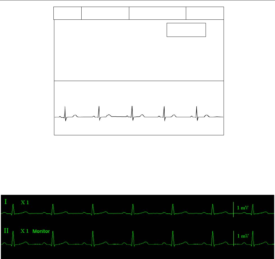
Telemetry Transmitter User Manual Monitoring ECG
60
HR bpm
II
PACE Icon
Bed No.Networking Icon Battery Status
Wireless Signal Icon
Figure 15-1
15.3.2 ECG Display on MFM-CMS
The figure below is ECG waveform for 5-lead. It is for reference only. The display on your
MFM-CMS depends on the configuration you have chosen.
15.4 Selecting Calculation Lead
Selecting calculation lead is operated on MFM-CMS.
Enter the Parameter Setup Window (way to entering refers to 8.2 Setting Parameters) > Click ECG on the
left physiological parameter list > Choose Calc. Lead > Click Update Monitor to confirm.
I, II and III lead are optional for 3-lead.
I, II, III, aVR, aVF, aVL, and V lead are optional for 5-lead.
Normal QRS complex should be:
The normal QRS should be either completely above or below the baseline and it should not
be biphasic. For paced patients, the QRS complexes should be at least twice the height of
pace pulses.
The QRS should be tall and narrow.
The P-waves and the T-waves should be less than 0.2 mV.
- 73 -

Telemetry Transmitter User Manual Monitoring ECG
15.5 Changing Size of ECG Waveform
Changing size of ECG waveform is operated on MFM-CMS.
Enter the Parameter Setup Window (way to entering refers to 8.2 Setting Parameters) > Click ECG on the
left physiological parameter list > Choose ECG Gain > Click Update Monitor to confirm.
X0.125 to make strength of ECG signal waveform of 1mV become 1.25mm;
X0.25 to make strength of ECG signal waveform of 1mV become 2.5mm;
X0.5 to make strength of ECG signal waveform of 1mV become 5mm;
X1 to make strength of ECG signal waveform of 1mV become 10mm;
X2 to make strength of ECG signal waveform of 1mV become 20mm;
X4 to make strength of ECG signal waveform of 1mV become 40mm;
Auto let the MFM-CMS choose the optimal adjustment factor for all the ECG waves.
NOTE:
The effect of ECG waveform gain is subject to the size of the waveform area. Whichever
waveform gain is chosen, the ECG waveform has to be displayed within the waveform
area.
15.6 Changing ECG Filter Settings
Changing ECG filter settings is operated on MFM-CMS.
Enter the Parameter Setup Window (way to entering refers to 8.2 Setting Parameters) > Click ECG on the
left physiological parameter list > Choose Filter > Click Update Monitor to confirm.
– Monitor: Use this mode under normal measurement conditions.
– Surgery: The filter reduces interference to the signal. It should be used if the signal is distorted
by high frequency or low frequency interference. High frequency interference usually results in
large amplitude spikes making the ECG signal look irregular. Low frequency interference usually
leads to a wandering or rough baseline. In the operating room, the Filter reduces artifacts. Under
normal measurement conditions, selecting Surgery may suppress the QRS complexes too much
and thus interfere with the clinical evaluation of the ECG displayed on the MFM-CMS.
–Diagnosis: Use when diagnostic quality is required. The unfiltered ECG waveform is displayed
so that changes such as R-wave notching or discrete elevation or depression of the ST segments
are visible.
15.7 ECG Alarm Settings
ECG alarm settings are operated on MFM-CMS. Use can open or close the ECG alarm.
Refer to 8.2.1 Parameters Alarm Setting for more information.
- 74 -
Telemetry Transmitter User Manual Monitoring ECG
15.8 Monitoring Procedure
15.8.1 Preparation
The skin is a poor conductor of electricity; therefore preparation of the patient's skin is important
to facilitate good electrode contact to skin.
Select sites with intact skin, without impairment of any kind.
Shave hair from sites, if necessary.
Wash sites thoroughly with soap and water. (Never use ether or pure alcohol, because this
increases skin impedance).
Rub the skin briskly to increase capillary blood flow in the tissues and remove skin scurf and
grease.
15.8.2 Connecting ECG Cables
1. Attach clip or snap to electrodes prior to placement.
2. Put the electrodes on the patient. Before attaching, apply some conductive jelly on the
electrodes if the electrodes are not electrolyte self-supplied.
3. Connect the electrode lead to the patient's cable.
4. Plug the patient cable into the ECG connector.
CAUTION
To protect the telemetry transmitter from damage during defibrillation, for accurate ECG
information and to protect against noise and other interference, use only ECG electrodes
and cables specified by EDAN.
15.9 Installing Electrodes
NOTE:
The following table gives the corresponding lead names used in Europe and America
respectively. (Lead names are represented by R, L, F, N, C, C1-C6 in Europe, whose
corresponding lead names in America are RA, LA, LL, RL, V, V1-V6.)
AHA (American Standard) IEC (Europe Standard)
Electrode Labels Color Electrode Labels Color
RA
White
R
Red
LA
Black
L
Yellow
LL
Red
F
Green
RL
Green
N
Black
V
Brown
C
White
- 75 -

Telemetry Transmitter User Manual Monitoring ECG
AHA (American Standard) IEC (Europe Standard)
V1
Brown/ Red
C1
White/ Red
V2
Brown/ Yellow
C2
White/ Yellow
V3
Brown/ Green
C3
White/ Green
V4
Brown/Blue
C4
White/ Brown
V5
Brown/Orange
C5
White/ Black
V6
Brown/Purple
C6
White/ Purple
15.9.1 Electrode Placement for 3-lead
Take the American standard for example, see the following figure:
■ RA placement - directly below the clavicle and near the right shoulder.
■ LA placement: directly below the clavicle and near the left shoulder.
■ LL placement - on the left hypogastrium.
Electrode Placement for 3-lead
15.9.2 Electrode Placement for 5-lead
Take the American standard for example; see the following figure:
■ RA placement: directly below the clavicle and near the right shoulder.
■ LA placement: directly below the clavicle and near the left shoulder.
■ RL placement: on the right hypogastrium.
■ LL placement: on the left hypogastrium.
■ V placement: on the chest, the position depends on your required lead selection.
- 76 -
Telemetry Transmitter User Manual Monitoring ECG
Electrode Placement for 5-lead
NOTE:
To ensure the patient safety, all leads must be attached to the patient.
For 5-lead, attach the V electrode to one of the indicated positions as below:
■ V1 On the 4th intercostal space at the right sterna margin.
■ V2 On the 4th intercostal space at the left sterna margin.
■ V3 Midway between V2 and V4 electrodes.
■ V4 On the 5th intercostal space at the left clavicular line.
■ V5 On the left anterior axillary line, horizontal with V4 electrode.
■ V6 On the left middle axillary line, horizontal with V4 electrode.
■ V3R-V6R On the right side of the chest in positions corresponding to those on the left.
■ VE Over the xiphoid position.
■ V7 On the 5th intercostal space at the left posterior axillary line of back.
■ V7R On the 5th intercostal space at the right posterior axillary line of back.
- 77 -
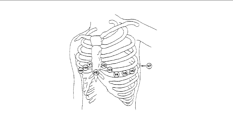
Telemetry Transmitter User Manual Monitoring ECG
V-Electrode Placement for 5-lead
15.10 Setting Alarm Source
Setting alarm source is operated on MFM-CMS.
Enter the Parameter Setup Window (way to entering refers to 8.2 Setting Parameters) > Click ECG on the
left physiological parameter list > Choose Alarm Source > Click Update Monitor to confirm.
HR: the telemetry transmitter considers the HR as HR/PR alarm source;
PR: the telemetry transmitter considers the PR as HR/PR alarm source;
AUTO: If the Alarm Source is set to Auto, the telemetry transmitter will use the heart rate from
the ECG measurement as the alarm source whenever the ECG measurement is switched on and at
least one ECG lead can be measured without a technical condition. The telemetry transmitter will
automatically switch to Pulse as the alarm source if:
–a valid ECG lead can no longer be measured and
–a pulse source is switched on and available.
The telemetry transmitter then uses the pulse rate from the measurement currently active as
system pulse. While PR is the alarm source, all arrhythmia and ECG HR alarms are switched off.
If an ECG lead becomes available again, the telemetry transmitter automatically uses HR as
alarm source.
15.11 Smart Lead Off
Choosing smart lead off is operated on MFM-CMS.
When Lead Type is 5 Leads and Smart LeadOff is set to On, if the selected ECG waveform
cannot be measured because of lead-off or other reasons, it will automatically switch to another
available lead channel via which a waveform can be measured. And the lead name above the
display ECG waveform also automatically turns into the current one.
- 78 -

Telemetry Transmitter User Manual Monitoring ECG
To change the smart lead off setting, enter the Parameter Setup Window (way to entering refers to 8.2
Setting Parameters) > Click ECG on the left physiological parameter list > Choose Smart
LeadOff > Click Update Monitor to confirm.
15.12 Setting Pace Status
Setting pace status is operated on MFM-CMS.
It is important to set the paced status correctly when you start monitoring ECG. To change the
paced status in the ECG Setup menu, enter the Parameter Setup Window (way to entering refers to 8.2
Setting Parameters) > Click ECG on the left physiological parameter list > Choose Pace > Click
Update Monitor to confirm.
When Pace is set to On:
- Pace Pulse Rejection is switched on. This means that pacemaker pulses are not counted as
extra QRS complexes.
- Paced symbol is displayed as | on the main screen.
NOTE:
1 When monitoring a patient with a pacemaker, set Pace to On. If monitoring a patient
without a pacemaker, set Pace to Off.
2 If Pace is set to On, the system will not perform some types of ARR analysis.
WARNING
Some pace pulses can be difficult to reject. When this happens, the pulses are counted
as a QRS complex, and could result in an incorrect HR and failure to detect cardiac arrest
or some arrhythmias. Keep pacemaker patients under close observation.
15.13 ECG Calibration
ECG calibration is operated on MFM-CMS. This item is used to calibrate ECG waveform.
To calibrate ECG, enter the Parameter Setup Window (way to entering refers to 8.2 Setting Parameters) >
Click ECG on the left physiological parameter list > Click Calibration to calibrate ECG
waveform. Then click Stop to end calibration.
NOTE:
The device can’t be monitored during ECG calibration.
15.14 ECG Waveform Settings
ECG waveform setting is operated on MFM-CMS and is applicable to the wave on MFM-CMS.
User can select an appropriate setting. The bigger the value is, the wider the waveform is.
6.25mm/s, 12.5mm/s, 25mm/s, 50mm/s are optional. Please refer to 6.4.1 Setting Waveforms for
more information.
- 79 -

Telemetry Transmitter User Manual Monitoring ECG
15.15 ST Segment Monitoring
Telemetry transmitter performs ST segment analysis on normal and atrially paced beats and
calculates ST segment elevations and depressions. This information can be displayed in the form
of ST numerics on telemetry transmitter and MFM-CMS(refer to 15.15.2 ST Display).
ST segment monitoring function is shut off by default. You can switch it to On when necessary.
NOTE:
1 ST-segment analysis is intended for use with adult patients only and is not clinically
validated for use with pediatric patients.
2 The ST algorithm has been tested for accuracy of the ST segment data. The
significance of the ST segment changes need to be determined by a clinician.
15.15.1 Open/ Close ST Analysis
Setting ST analysis is operated on MFM-CMS.
To set ST, enter the Parameter Setup Window (way to entering refers to 8.2 Setting Parameters) > Click
ECG on the left physiological parameter list > Choose ON or OFF from ST Analysis, or click
ST on the left physiological parameter list to choose ON or OFF> Click Update Monitor to
confirm.
15.15.2 ST Display
The ST display on telemetry transmitter is as figure 2-4 or figure 2-5.
The ST display on MFM-CMS is on the following areas:
Area 1: ST value area on the right of Single Bed View Sub-Window;
Area 2: parameter value area of patient sector (under the condition that ST should be set as the
active parameter. Detailed operations refer to 6.4.2 Setting Parameters).
15.15.3 ST Alarm Settings
ST alarm settings are operated on MFM-CMS. Please refer to 8.2.1 Parameters Alarm Setting for
more alarm settings.
ST value range is from 2.0 mV to -2.0 mV. The minimum alarm high limit shall be 0.2 mV higher
than the maximum alarm low limit.
15.15.4 About ST Measurement Points
The ST value for each beat complex is the vertical difference between the ISO point and the ST
point, as shown in the diagram below. The isoelectric (ISO) point provides the baseline, and the
ST point is at the midpoint of the ST segment. The J point is where the QRS complex changes its
slope; as it is a fixed distance away from the ST point, it can be useful to help you position the ST
point correctly.
- 80 -
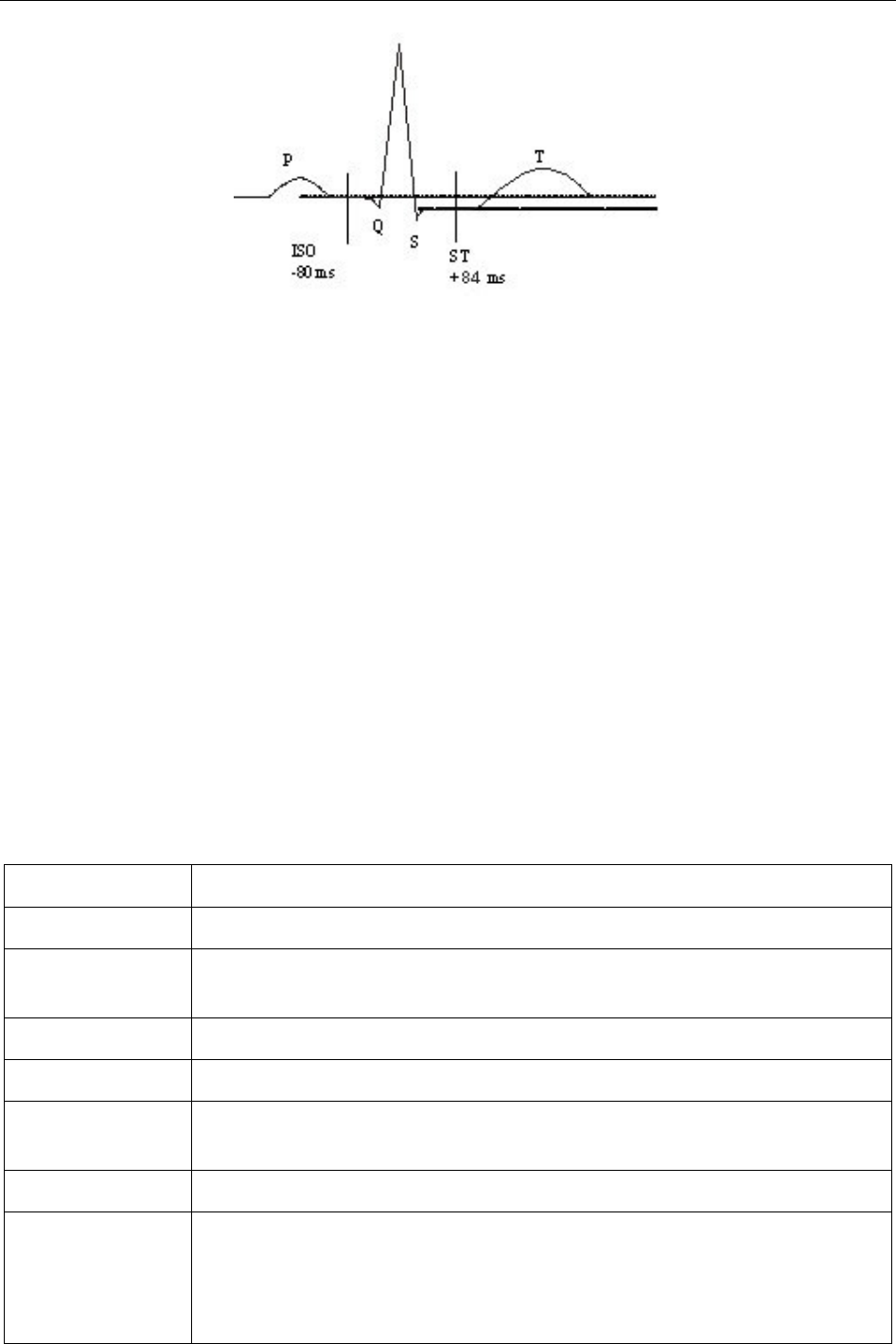
Telemetry Transmitter User Manual Monitoring ECG
DEF POINT
About ISO and ST measurement points:
For telemetry transmitters, the location of ISO and ST measurement points is not adjustable. Its
initial value for ST testing points is +84ms by default. ST analysis takes no account of abnormal
QRS wave.
15.16 Arr. Monitoring
15.16.1 Arrhythmia Analysis
The arrhythmia algorithm is used to monitor ECG of adult patients in clinics, and detect the
changes of heart rate and ventricular rhythm, and also save arrhythmia events and generate
alarming information. The arrhythmia analysis is not clinically validated for use with neonatal
and pediatric patients. Arrhythmia algorithm can monitor paced and non-paced patients. Qualified
personnel can use arrhythmia analysis to evaluate patient’s condition (such as heart rate, PVCs
frequency, rhythm and ectopic beat) and decide the treatment. Besides detecting change of ECG,
arrhythmia algorithm can also monitor patients and give proper alarm for arrhythmia.
Telemetry transmitter can support up to 16 different arrhythmia analyses.
ARR Types
Occurring Condition
ASYSTOLE
No QRS is detected for 4 consecutive seconds
VFIB/VTAC
4 consecutive seconds' fibrillation wave occurs, or each RR interval for 5
consecutive ventricular beats is less than 600 ms.
VT>2
3 ≤ the number of consecutive PVCs < 5
COUPLET
2 consecutive PVCs
BIGEMINY
A dominant rhythm of N, V, N, V (N = supraventricular beat, V =
ventricular beat) was detected.
TRIGEMINY
A dominant rhythm of N, N, V, N, N,V.
R ON T
A type of single PVC under the condition that HR<100,R-
R interval is less
than 1/3 the average interval, followed by a compensating pause of 1.25X
the average R-
R interval (the next R wave advances onto the previous T
wave).
- 81 -

Telemetry Transmitter User Manual Monitoring ECG
ARR Types
Occurring Condition
PVC
Single PVC detected in normal heartbeats.
TACHY Adult: RR interval for 5 consecutive QRS complex ≤ 0.5s.
Pediatric: RR interval for 5 consecutive QRS complex ≤ 0.375s.
BRADY Adult: RR interval for 5 consecutive QRS complex ≥ 1.5s.
Pediatric: RR interval for 5 consecutive QRS complex ≥ 1s.
MISSED BEATS If HR < 120 bpm, no beats are detected for
1.75 times average RR interval;
or if HR ≥ 120 bpm, no beats are detected for one second.
IRR
Consistently irregular heart rhythm
PNC
PACE NOT CAPTURE: no QRS complex detected in 300ms after a pace
pulse.
PNP PACE
R NOT PACED: no pace pulse detected in 1.75 times RR interval
after a QRS complex.
VBRADY
VENTRICULAR BRADYCARDIA: Each RR interval for 5 consecutive
ventricular beats > 1000 ms.
VENT VENTRICULAR RHYTHM: Each RR interval for 5
consecutive
ventricular beats ranges from 600 ms to 1000 ms.
15.16.2 ARR Analysis Menu
15.16.2.1 Switching ARR Analysis On and Off
Switching ARR on or off is operated on MFM-CMS.
Enter the Parameter Setup Window (way to entering refers to 8.2 Setting Parameters) > Click ECG on the
left physiological parameter list > Choose ARR Analysis, or click ECG ARR on the left
physiological parameter list to choose ARR Analysis > Click Update Monitor to confirm.
15.16.2.2 PVCs Alarm Settings
PVCs alarm settings are operated on MFM-CMS. Please refer to 8.2.1 Parameters Alarm Setting
for more alarm settings.
Select On in the menu to enable prompt message when an alarm occurs; select Off to disable the
alarm function, and there will be a symbol beside PVCs.
- 82 -

Telemetry Transmitter User Manual Monitoring ECG
WARNING
When the PVCs Alarm is set to OFF, MFM-CMS won’t give an alarm prompt even if an
alarm occurs. In order to avoid endangering the patient’s life, the user should use this
function cautiously.
15.16.2.3 ARR Relearning
ARR relearning is operated on MFM-CMS.
Enter the Parameter Setup Window (way to entering refers to 8.2 Setting Parameters) > Click ECG ARR
on the left physiological parameter list > Click ECG Selflearn > Click Update Monitor to
confirm.
Pick this item to start a learning procedure, and ECG ARR LEARNING is displayed on the
screen. The ECG ARR LEARNING will start in the following status:
Connecting leads;
Starting ARR learning manually;
Switching calculation leads.
15.16.2.4 ARR Alarm Settings
ARR alarm settings are operated on MFM-CMS. Please refer to 8.2.1 Parameters Alarm Setting
for more alarm settings.
The users can switch on or off all arrhythmia alarms by ARR alarm settings. And some
arrhythmia alarms can be individually switched on or off. They are: R-ON-T, VT>2, COUPLET,
PVC, BIGEMINY, TRIGEMINY, TACHY, BRADY, MISSED BEATS, IRR, PNC, PNP,
VBRADY and VENT. Some arrhythmia alarms are preset to be on and cannot be turned off.
They are ASYSTOLE and VFIB/VTAC.
- 83 -

Telemetry Transmitter User Manual Monitoring RESP
Chapter 16 Monitoring RESP
16.1 Overview
Telemetry transmitter measures respiration from the amount of thoracic impedance between two
ECG electrodes. The change of impedance between the two electrodes, (due to the thoracic
movement), produces a respiratory waveform on the screen.
16.2 RESP Safety Information
WARNING
1 The respiration measurement does not recognize obstructive and mixed apneas - it
only indicates an alarm when a pre-adjusted time has elapsed since the last detected
breath.
2 If operating under conditions according to the EMC Standard EN 60601-1-2 (Radiated
Immunity 3V/m), field strengths above 1V/m may cause erroneous measurements at
various frequencies. Therefore it is recommended to avoid the use of electrically
radiating equipment in close proximity to the respiration measurement unit.
3 Cardiogenic artifact in impedance respiration monitoring may make it difficult to detect
breaths or may otherwise be counted as breaths. In some instances, the breath rate
may also correspond to the heart rate making it difficult to determine if the signal is
due to breathing or the cardiac cycle. Do not rely on RESP monitoring as the sole
method for detecting cessation of breathing. Follow hospital guidelines and best
clinical practices for apnea detection including monitoring additional parameters that
indicate the patient’s oxygenation status, such as EtCO2 and SpO2.
NOTE:
The RESP monitoring is not recommended to be used on patients who are very active, as
this can cause false alarms.
16.3 Electrode Placement for Monitoring RESP
Correct patient skin preparation techniques for electrode placement are important for RESP
measurement: you will find this information in the chapter on ECG.
The RESP signal is always measured between two of the ECG electrodes. There is only one
standard ECG lead for telemetry transmitter: II lead (RA and LL).
- 84 -
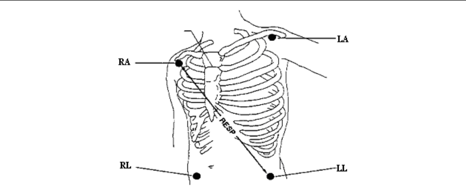
Telemetry Transmitter User Manual Monitoring RESP
Electrodes Placement for 5-lead
16.4 Cardiac Overlay
Cardiac activity that affects the RESP waveform is called cardiac overlay. It happens when the
RESP electrodes pick up impedance changes caused by the rhythmic blood flow. Correct
electrode placement can help to reduce cardiac overlay: avoid the liver area and the ventricles of
the heart in the line between the respiratory electrodes.
16.5 Chest Expansion
Some patients, expand their chests laterally. In these cases it is best to place the two respiratory
electrodes in the right midaxillary and left lateral chest areas at the patient’s maximum point of
breathing movement to optimize the respiratory wave.
16.6 Abdominal Breathing
Some patients with restricted chest movement breathe mainly abdominally. In these cases, you
may need to place the left leg electrode on the left abdomen at the point of maximum abdominal
expansion to optimize the respiratory wave.
NOTE:
Place the red and green electrodes diagonally to optimize the respiration waveform.
Avoid the liver area and the ventricles of the heart in the line between the RESP
electrodes so as to avoid cardiac overlay or artifacts from pulsating blood flow.
16.7 Selecting RESP Lead
II lead is constant as the RESP lead.
16.8 Changing the Apnea Time
Changing the apnea time is operated on MFM-CMS.
- 85 -

Telemetry Transmitter User Manual Monitoring RESP
The apnea alarm is a high priority red alarm used to detect apneas. The apnea alarm delay time
defines the time period between the point where the telemetry transmitter cannot detect any
respiration activity and the indication of the apnea alarm.
Enter the Parameter Setup Window (way to entering refers to 8.2 Setting Parameters) > Click RESP on the
left physiological parameter list > Click Apnea Time (10s, 15s, 20s, 25s, 30s, 35s and 40s
are optional) > Click Update Monitor to confirm.
NOTE:
Apnea time means the time period with no apnea alarm. If the actual apnea time of
patient is over that that period, MFM-CMS will give apnea alarm. Please use it cautiously.
16.9 Changing the Size and Speed of the Respiration Waveform
RESP waveform setting is operated on MFM-CMS and is applicable to the waveform on
MFM-CMS.
To changing the size of RESP waveform, enter the Parameter Setup Window (way to entering refers
to 8.2 Setting Parameters) > Click RESP on the left physiological parameter list > Click Gain
(X0.25, X0.5, X1, X2, X3, X4 and X5 are optional) > Click Update Monitor to confirm.
User can select an appropriate waveform speed. The bigger the value is, the wider the
waveform is. 6.25mm/s, 12.5mm/s, 25mm/s are optional.
Please refer to 6.4.1 Setting Waveforms for more information.
16.10 RESP Alarm Settings
RESP alarm settings are operated on MFM-CMS. Use can open or close the RESP alarm.
Please refer to 8.2.1 Parameters Alarm Setting for more alarm settings.
- 86 -

Telemetry Transmitter User Manual Monitoring SpO2
Chapter 17 Monitoring SpO2
17.1 Overview
SpO2 is based on the absorption of pulse blood oxygen to red and infrared light by means of
finger sensor and SpO2 measuring unit. SpO2 Plethysmogram measurement is employed to
determine the oxygen saturation of hemoglobin in the arterial blood. If, for example, 97% of the
hemoglobin molecules in the red blood cells of the arterial blood combine with oxygen, then the
blood has a SpO2 oxygen saturation of 97%. The SpO2 numeric on the telemetry transmitter will
read 97%. The SpO2 numeric shows the percentage of hemoglobin molecules which have
combined with oxygen molecules to form oxyhemoglobin. The SpO2/PLETH parameter can also
provide a pulse rate signal and a plethysmogram wave.
17.2 SpO2 Safety Information
WARNING
1 If the SpO2 sensor cannot work properly, please reconnect the sensor or change a
new one.
2 Do not use the sterile supplied SpO2 sensors if the packaging or the sensor is
damaged and return them to the vendor.
3 Prolonged and continuous monitoring may increase the risk of unexpected change of
dermal condition such as abnormal sensitivity, rubescence, vesicle, repressive
putrescence, and so on. It is especially important to check the sensor placement for
the patients of poor perfusion or immature dermogram by light collimation and proper
attaching strictly according to changes of the skin. More frequent examinations may
be required for different patients.
4 Tissue damage may be caused by incorrect application or prolonged measurement
duration using the sensor (more than 4 hours). Inspect the sensor periodically
according to the sensor user manual.
5 Use only EDAN permitted sensors and extension cables with the oximeter. Other
sensors or extension cables may cause improper telemetry transmitter performance
and/or minor personal injury.
NOTE:
1 Make sure the nail covers the light window. The wire should be on the backside of the
hand.
2 SpO2 waveform is not proportional to the pulse volume.
3 Avoid placing the sensor on extremities with an arterial catheter, or intravascular
venous infusion line.
4 Don’t use the functional tester or patient simulator to assess the SpO2 accuracy.
- 87 -

Telemetry Transmitter User Manual Monitoring SpO2
5 The device is calibrated to display functional oxygen saturation.
6 The materials with which the patient or any other person can come into contact
conform with the standard of EN ISO 10993-1: 2009.
7 SpO2 waveform is not proportional to the pulse volume.
8 When the SpO2 value is potentially incorrect, it will display “?”.
17.3 Measuring SpO2
1. Select the correct Type in the patient management window (Adult/ Pediat) and click Update
Monitor to confirm, as this is used to optimize the calculation of the SpO2 and pulse
numerics.
2. During measurement, ensure that the application site:
– has a pulsatile flow, ideally with a good circulation perfusion.
– has not changed in its thickness, causing an improper fit of the sensor.
17.4 Measurement Procedure
1. Switch on telemetry monitoring system.
2. Attach the sensor to the appropriate site of the patient finger.
3. Plug the connector of the sensor extension cable into the SpO2 socket on telemetry
transmitter.
Mounting of the Sensor
WARNING
Inspect the application site every two to three hours to ensure skin quality and correct
optical alignment. If the skin quality changes, move the sensor to another site. Change
the application site at least every four hours.
NOTE:
Injected dyes such as methylene blue or intravascular dyshemoglobins such as
methemoglobin and carboxyhemoglobin may lead to inaccurate measurements.
Interference can be caused by:
High levels of ambient light or strobe lights or flashing lights (such as fire alarm lamps).
- 88 -

Telemetry Transmitter User Manual Monitoring SpO2
(Hint: cover application site with opaque material.)
High-frequency electrical noise, including electro-surgical apparatus and defibrillators
Intravascular dye injections
Significant concentrations of dysfunctional hemoglobin, such as carboxyhemoglobin and
methemoglobin
Excessive patient movement and vibration
Improper sensor application
Low perfusion or high signal attenuation
Venous pulsation
Placement of the sensor on an extremity that has a blood pressure cuff, arterial catheter, or
intravascular line
17.5 Assessing the Validity of a SpO2 Reading
You can check the quality of the pleth wave and the stability of the SpO2 values to assess whether
the sensor functions properly and whether the SpO2 readings are valid. Always use these two
indications simultaneously to assess the validity of a SpO2 reading.
Generally, the quality of the SpO2 pleth wave reflects the quality of the light signals obtained by
the sensor. A wave of poor quality manifests a decline of the signal validity. On the other hand,
the stability of the SpO2 values also reflects the signal quality. Different from varying SpO2
readings caused by physiological factors, unstable SpO2 readings are resulted from the sensor’s
receiving signals with interference. The problems mentioned above may be caused by patient
movement, wrong sensor placement or sensor malfunction. To obtain valid SpO2 readings, try to
limit patient movement, check the placement of the sensor, measure another site or replace the
sensor.
NOTE:
1. The SpO2 accuracy has been validated in human studies against arterial blood
sample reference measured with a CO-oximeter. Pulse oximeter measurements are
statistically distributed, only about two-thirds of the measurements can be expected
to fall within the specified accuracy compared to CO-oximeter measurements. The
volunteer population in the studies composed of local healthy men and women from
age 19 to 37, with various skin pigmentations.
2. The pulse rate accuracy is obtained by comparison to the pulse rate generated with
an arterial oxygen simulator (also an electronic pulse simulator).
- 89 -

Telemetry Transmitter User Manual Monitoring SpO2
17.6 SpO2 Alarm Delay
There is a delay between a physiological event at the measurement site and the corresponding
alarm at the MFM-CMS. This delay has two components:
1. The time between the occurrence of the physiological event and when this event is
represented by the displayed numerical values. This delay depends on the algorithmic
processing time and the sensitivity setting. The lower the sensitivity configured, the longer
the time needed until the numerical values reflect the physiological event.
2. The time between the displayed numerical values exceeding an alarm limit and the alarm
indication on the MFM-CMS. This delay is the combination of the configured alarm delay
time plus the general system delay time.
17.7 Setting Sensitivity
Setting sensitivity is operated on MFM-CMS.
The different sensitivity indicates different refresh frequency. High indicates the refresh
frequency of SpO2 value is the most frequent. To change the sensitivity, please:
Enter the Parameter Setup Window (way to entering refers to 8.2 Setting Parameters) > Click
SpO2 on the left physiological parameter list > Click Sensitivity (High, Med and Low are
optional) > Click Update Monitor to confirm.
17.8 SpO2 Alarm Settings
SpO2 alarm settings are operated on MFM-CMS. Use can open or close the ECG alarm.
Please refer to 8.2.1 Parameters Alarm Setting for more alarm settings.
- 90 -

Telemetry Transmitter User Manual Monitoring PR
Chapter 18 Monitoring PR
18.1 Overview
The pulse numeric counts the arterial pulsations that result from the mechanical activity of the
heart in beats per minute (bpm). You can display a pulse from any measured SpO2 signal.
18.2 Selecting the Active Alarm Source
In most cases, the HR and Pulse numerics are identical. In order to avoid simultaneous alarms on
HR and Pulse, the telemetry transmitter uses either ECG or Pulse as its active alarm source.
Selecting active alarm source is operated on MFM-CMS.
Enter the Parameter Setup Window (way to entering refers to 8.2 Setting Parameters) > Click PR
on the left physiological parameter list > Click Alarm Source (HR, PR and AUTO are
optional) > Click Update Monitor to confirm.
HR: if you want HR to be the alarm source for HR/Pulse.
PR: if you select Pulse as the alarm source, ECG HR alarms are switched off.
AUTO: If the Alarm Source is set to Auto, the telemetry transmitter will use the heart rate
from the ECG measurement as the alarm source whenever the ECG measurement is switched
on and at least one ECG lead can be measured without a technical condition. The telemetry
transmitter will automatically switch to Pulse as the alarm source if:
–a valid ECG lead can no longer be measured and
–a pulse source is switched on and available.
The telemetry transmitter then uses the pulse rate from the measurement currently active as
system pulse. While PR is the alarm source, all arrhythmia and ECG HR alarms are switched
off. If an ECG lead becomes available again, the telemetry transmitter automatically uses HR
as alarm source.
NOTE:
Pulse alarms are only generated when the active alarm source is set to PR, a pulse
source is set as system pulse and pulse alarms are switched on.
18.3 PR Alarm Settings
PR alarm settings are operated on MFM-CMS. Use can open or close the ECG alarm.
Please refer to 8.2.1 Parameters Alarm Setting for more alarm settings.
- 91 -

Telemetry Transmitter User Manual Using Battery
Chapter 19 Using Battery
Telemetry transmitter supports 2 sections of AA batteries which cannot be charged directly
in battery bin.
CAUTION
Remove the batteries from the telemetry transmitter if they are not used for a longer
period of time.
19.1 Battery Status on Screen
The screen of telemetry transmitter as well as technical alarm/ indicator area in patient sector
of MFM-CMS (refer to 6.2 Networked Monitoring Display) displays battery status. Higher the
battery surplus’ level is, more power the battery has.
The following is the definition about the battery level under the typical testing environment.
Battery Level Power Surplus
Level 0 near to using up
Level 1 work continuously no less than 6 mins
Level 2 work continuously no less than 20 hours
Level3 work continuously no less than 40 hours
Level 4 work continuously no less than 60 hours
The typical testing environment includes:
Temperature 25±2℃, SpO2 module unconnected, continuously testing ECG of 3-lead
(pace off and RESP off), typical network environment with no interference, screen closed and
at least 5 mins of continuous work.
In actual application, power surplus may be different with the table above due to batteries’
performance.
Telemetry transmitter will sent technical alarm information of low battery power to
MFM-CMS informing user of changing battery when battery power is 0-level. Meanwhile,
telemetry transmitter gives out a periodic sound of “du-du-du” whose interval is 10 seconds till
shutdown.
- 92 -

Telemetry Transmitter User Manual Using Battery
WARNING
1. Please use the specified battery and confirm its quality.
2. Before installing or replacing battery, be sure to read the user manual and safety
precautions thoroughly.
3. The service life of the batteries depends on the service frequency and time. The
service life of the batteries may shorten if they are used inappropriately.
4. Periodic checks on the battery performance are required. Change the batteries if
necessary.
5. Do not place battery in the monitor with the (+) and (-) in the wrong way.
6. Do not connect the positive (+) and negative (-) terminals with metal objects, and do
not put the batteries together with metal objects, which can result in short circuits.
7. Do not unplug the batteries when monitoring.
8. Do not heat or throw the batteries into a fire.
9. Do not use, leave the batteries close to fire or other places where temperature may
be above 60°C.
10. Do not immerse, throw, or wet the batteries in water/seawater.
11. Do not destroy the batteries: do not pierce the batteries with a sharp object such as a
needle; do not hit with a hammer, step on or throw or drop to cause strong shock; do
not disassemble or modify the batteries.
12. Do not disassemble the battery.
13. Do not use with new and old batteries at the same time, or use with alkaline and
nickel-metal hydride battery.
14. Do not solder the leading wire and the battery terminal directly.
15. If liquid leaking from the batteries gets into your eyes, do not rub your eyes. Wash
them well with clean water and go to see a doctor immediately. If liquid leaks of the
batteries splash onto your skin or clothes, wash well with fresh water immediately.
16. Keep away from fire immediately when leakage or foul odor is detected.
17. Stop using the batteries if abnormal heat, odor, discoloration, deformation or
abnormal condition is detected during use, charge, or storage. Keep it away from the
telemetry transmitter.
18. Do not use a battery with serious scar or deformation.
19. Use the batteries with similar performance, which can extend the service life of the
batteries. If one of the two batteries is malfunctioning, it is recommended to change
both of the two batteries.
20. Do not replace the batteries during monitoring patients
- 93 -

Telemetry Transmitter User Manual Using Battery
19.2 Replacing the Battery
To install or replace the battery, please refer to 4.1.1 Battery Installing and Replacing.
19.3 Recycling the Battery
When the battery no longer holds a charge, it should be replaced. Remove the old battery from
the battery bin and recycle it properly.
WARNING
Do not disassemble the battery, put it into fire or cause it to short circuit. It may ignite,
explode or leak, causing personal injury.
- 94 -

Telemetry Transmitter User Manual Safety
Chapter 20 Safety
20.1 Control and Safety Index
Windows XP/ Windows 7 workstation, printer, UPS (optional), Keyboard, display and mouse
should accord with the corresponding safety requirements. They are not suitable for installing in
the patients’ environment.
20.2 Characteristics
The standard MFM-CMS includes the following characteristics:
Up to 240 hours of trend data storage and review
Storage of patients’ history data
96-hour full disclosure physiological waveforms
12-lead ECG display
12-hour short trend data
Printing report
Monitoring 64 patients simultaneously
Transfer waveforms, parameters, alarms, etc.
- 95 -

Telemetry Transmitter User Manual Care and Cleaning
Chapter 21 Care and Cleaning
Use only the EDAN-approved substances and methods listed in this chapter to clean or disinfect
your equipment. Warranty does not cover damage caused by using unapproved substances or
methods.
EDAN Instruments has validated the cleaning and disinfection instructions included in this User
Manual. It is the responsibility of the healthcare professional to ensure that the instructions are
followed so as to ensure adequate cleaning and disinfection
21.1 General Points
Keep your device, cables and accessories free of dust and dirt. To prevent the device from
damage, please follow the procedure:
Use only recommended cleaning substances and disinfectants listed in this manual.
Others may cause damage (not covered by warranty), reduce product lifetime or cause
safety hazards.
Always dilute according to the manufacturer’s instructions.
Unless otherwise specified, do not immerse any part of the equipment or any accessories
in liquid.
Do not pour liquid onto the system.
Do not allow liquid to enter the case.
Never use abrasive material (such as steel wool or silver polish).
Inspect the telemetry transmitter and reusable accessories after they are cleaned and
disinfected.
CAUTION
If you spill liquid on the equipment, battery, or accessories, or they are accidentally
immersed in liquid, contact your service personnel or EDAN service engineer.
21.2 Cleaning
If the device or accessory has been in contact with the patient, then cleaning and disinfection is
required after every use. If there has been no patient contact and there is no visible contamination
then daily cleaning and disinfection is appropriate.
The validated cleaning agents for cleaning the telemetry transmitter and reusable accessories are:
Mild near neutral detergent
Ethanol (75%)
Isopropanol (70%)
Cleaning agents should be applied and removed using a clean, soft, non-abrasive cloth or paper
towel.
- 96 -

Telemetry Transmitter User Manual Care and Cleaning
21.2.1 Cleaning the Telemetry Transmitter
WARNING
Before cleaning the device, make sure that the telemetry transmitter is switched off and
take the battery out.
To surface-clean the telemetry transmitter, follow these steps:
1. Switch off the telemetry transmitter and take the battery out.
2. Wipe the entire exterior surface, including the screen, of the equipment using a soft cloth
dampened with the cleaning solution thoroughly until no visible contaminants remain..
3. Wipe off the cleaning solution with a fresh cloth or towel, dampened with tap water after
cleaning until no visible cleaning agent remains..
4. Dry the telemetry transmitter in a ventilated and cool place.
21.2.2 Cleaning the Reusable Accessories
21.2.2.1 Cleaning the ECG Cable Assembly
1. Wipe the cable assembly with a soft cloth dampened with the cleaning solution until no
visible contaminants remain.
2. Wipe off the cleaning solution with a fresh cloth or towel, dampened with tap water after
cleaning until no visible cleaning agent remains..
3. Wipe off with a dry cloth to remove residual moisture.
4. Leave the cable assembly to air dry.
21.2.2.2 Cleaning the SpO2 Sensor
1. Wipe the surfaces of the sensor and cable using a soft cloth dampened with the cleaning
solution until no visible contaminants remain.
2. Wipe the patient contact area of the sensor with the cotton swab dampened with the cleaning
solution. until no visible contaminants remain
3. Wipe off the cleaning solution with a fresh cloth or towel, dampened with tap water after
cleaning until no visible cleaning agent remains.
4. Wipe off with a dry cloth to remove residual moisture.
5. Leave the sensor to air dry.
21.2.2.3 Cleaning Leather Cover
1. Wipe leather cover with a soft cloth dampened with the cleaning solution until no visible
contaminants remain.
2. Wipe off the cleaning solution with a fresh cloth or towel, dampened with tap water after
cleaning until no visible cleaning agent remains..
- 97 -

Telemetry Transmitter User Manual Care and Cleaning
3. Wipe off with a dry cloth to remove residual moisture.
4. Leave leather cover to air dry.
21.3 Disinfection
For telemetry transmitter or accessories, low level disinfection is appropriate. Clean the telemetry
transmitter and reusable accessories before they are disinfected. The validated disinfectants for
cleaning the telemetry transmitter and reusable accessories are:
Ethanol (75%)
Isopropanol (70%)
If Ethanol or Isopropanol is used for both cleaning and disinfecting, then a new cloth is required
to be used for the disinfection step.
WARNING
The telemetry transmitter and reusable accessories shall be disinfected regularly to avoid
patient cross infection.
21.3.1 Disinfecting the Telemetry Transmitter
WARNING
Before disinfecting the telemetry transmitter, make sure that the telemetry transmitter is
switched off and take batteries out.
To disinfect the telemetry transmitter, follow these steps:
1. Switch off the telemetry transmitter and take batteries out.
2. Wipe the display screen using a soft, clean cloth dampened with the disinfectant solution.
3. Wipe the exterior surface of the equipment using a soft cloth dampened with the disinfectant
solution.
4. Wipe off the disinfectant solution with a dry cloth after disinfection if necessary.
5. Dry the telemetry transmitter for at least 30 minutes in a ventilated and cool place.
21.3.2 Disinfecting the Reusable Accessories
21.3.2.1 Disinfecting the ECG Cable Assembly
1. Wipe the cable assembly with a soft cloth dampened with the disinfectant solution.
2. Wipe off the disinfectant solution with a dry cloth after disinfection.
3. Leave the cable assembly to air dry for at least 30 minutes.
- 98 -

Telemetry Transmitter User Manual Care and Cleaning
21.3.2.2 Disinfecting the SpO2 Sensor
1. Wipe the surfaces of the sensor and cable using a soft cloth dampened with the disinfection
solution.
2. Wipe the patient contact area of the sensor with the cotton swab dampened with the
disinfection solution.
3. Wipe off the disinfection solution with a dry cloth after disinfection.
4. Leave the sensor to air dry for at least 30 minutes.
21.3.2.4 Cleaning Leather Cover
1. Wipe leather cover with a soft cloth dampened with the disinfectant solution.
2. Wipe off the disinfectant solution with a dry cloth after disinfection.
3. Leave leather cover to air dry for at least 30 minutes.
21.3.2.4 Cleaning and Disinfecting Other Accessories
For cleaning and disinfecting other accessories, refer to the instructions delivered with the
accessories. If the accessories are not accompanied by instructions, refer to this manual for the
methods of cleaning and disinfecting the telemetry transmitter.
- 99 -

Telemetry Transmitter User Manual Maintenance
Chapter 22 Maintenance
WARNING
1 Failure on the part of the responsible individual hospital or institution employing the
use of this equipment to implement a satisfactory maintenance schedule may cause
undue equipment failure and possible health hazards.
2 If you discover a problem with any of the equipment, contact your service personnel,
or your authorized supplier.
22.1 Inspecting
The overall check of the telemetry transmitter, including the safety check, should be performed
only by qualified personnel every 24 months, and each time after fix up.
The following items should be checked:
If the environment condition and power supply meet requirement.
If the power supply cord has damage and insulativity meets requirement.
If the device and accessories have damage.
Specified accessories.
If the alarm system can work properly.
If the printer can work properly and the paper meets the requirement.
Battery performance
If all monitoring functions are in good conditions.
If the grounding resistance and leakage current meet requirement.
If any damage or abnormality is found, please don’t use the telemetry transmitter and contact
local Customer Service Center.
22.2 Maintenance Task and Test Schedule
Maintenance shall be carried out at least once every two years, or as specified by local laws. The
following tasks are for EDAN-qualified service professionals only. Contact an EDAN-qualified
service provider if your device needs a safety or performance test. Clean and disinfect equipment
to decontaminate it before testing or maintaining it.
Maintenance and Test Schedule
Frequency
Safety checks. Selected tests on
the basis of IEC60601-1
At least once every two years, or as needed, after any
repairs where the power supply is removed or replaced,
or if the telemetry transmitter has been dropped.
Check all monitoring functions
and measuring functions
At least once every two years, or as needed.
- 100 -

Telemetry Transmitter User Manual Warranty and Service
Chapter 23 Warranty and Service
23.1 Warranty
EDAN warrants that EDAN’s products meet the labeled specifications of the products and will be
free from defects in materials and workmanship that occur within warranty period.
The warranty is void in cases of:
a) damage caused by mishandling during shipping.
b) subsequent damage caused by improper use or maintenance.
c) damage caused by alteration or repair by anyone not authorized by EDAN.
d) damage caused by accidents.
e) replacement or removal of serial number label and manufacture label.
If a product covered by this warranty is determined to be defective because of defective materials,
components, or workmanship, and the warranty claim is made within the warranty period, EDAN
will, at its discretion, repair or replace the defective part(s) free of charge. EDAN will not provide
a substitute product for use when the defective product is being repaired.
23.2 Contact information
If you have any question about maintenance, technical specifications or malfunctions of devices,
contact your local distributor.
Alternatively, you can send an email to EDAN service department at: support@edan.com.cn.
- 101 -

Telemetry Transmitter User Manual Accessories
Chapter 24 Accessories
You can order accessories from EDAN supplies at www.edan.com.cn or consult your local
EDAN representative for details.
WARNING
1 Never reuse disposable transducers, sensors, accessories and their casing that are
intended for single use; or only use them on a single patient. Reuse may compromise
device functionality and system performance and cause a potential hazard.
2 Use only EDAN-approved accessories. Using non-EDAN-approved accessories may
compromise device functionality and system performance and cause a potential
hazard. It is not recommended to use accessories supplied by EDAN with patient
monitors or telemetry transmitters by other manufacturers.
3 Do not use a sterilized accessory if its casing is damaged.
NOTE:
Transducers and sensors have a limited shelf life. Refer to the package labeling.
The following cables may not all be available in all countries. Please check availability with your
local EDAN supplier.
24.1 ECG Accessories
Part Number Accessories
01.57.471397 3-lead, IEC, snap, adult, limb wires for telemetry transmitter
01.57.471398 3-lead, AHA, snap, adult, limb wires for telemetry transmitter
01.57.471399 3-lead, IEC, clip, adult, limb wires for telemetry transmitter
01.57.471400 3-lead, AHA, clip, adult, limb wires for telemetry transmitter
01.57.471401 5-lead, IEC, snap, adult, limb wires for telemetry transmitter
01.57.471402 5-lead, AHA, snap, adult, limb wires for telemetry transmitter
01.57.471403 5-lead, IEC, clip, adult, limb wires for telemetry transmitter
01.57.471404 5-lead, AHA, clip, adult, limb wires for telemetry transmitter
01.57.471276
ECG CONDUCTIVE ADHESIVE ELECTRODES, TYCO
KENDALL MEDI TRACE 210, 10PCS/package
01.57.471056 Adult Disposable Adhesive Electrodes, TYCO H99SG,30PCS/
package, CE
- 102 -

Telemetry Transmitter User Manual Accessories
01.57.471057 Children
Disposable Adhesive Electrodes, TYCO H124SG,
50PCS/package,CE
01.57.471060 Adult Disposable Adhesive Electrodes, TYCO Medi-
Trace 200,
100PCS/ package, FDA
24.2 SpO2 Accessories
NOTE:
The information about wavelength range can be especially useful to clinicians (for
instance, when photodynamic therapy is performed).
Part Number Accessories
For EDAN Module
02.01.210120
EDAN SH1 Adult Reusable SpO2
Sensor (DB9) (Only compatible
with EDAN SpO2 module and EDAN SpO2
Extension cable ), 1m
(finger type, patient size>40kg)
02.01.210122
EDAN SH4 Adult Silicone Soft-tip SpO2 Sensor (DB9) (Immersion
Disinfection) (Only compatible with EDAN SpO2 module and EDAN
SpO2 Extension cable), 1m (finger type, patient size>50kg)
02.01.210121
EDAN SH5 pediatric Silicone Soft-tip SpO2
Sensor (DB9) (Only
compatible with EDAN SpO2 module and EDAN SpO2 Extension
cable), 1m (finger type, patient size: 10kg to 50kg)
01.57.471235 EDAN Adult Single-Patient SpO2 sensor SHD-
A (forefinger, for
patients over 30kg)
01.57.471236 EDAN Pediatrics Single-Patient SpO2 sensor SHD-
P (forefinger, for
patients between 10kg to 50kg)
01.57.471237 EDAN Infant Single-Patient SpO2 sensor SHD-I (big toe, for patients
between 3kg to 20kg)
01.57.471405 SpO2 Extension cable for telemetry transmitter
01.57.040196 Adult Disposable SpO2 Sensor (DB9)
01.57.040197 Pediatric Disposable SpO2 Sensor (DB9)
01.57.040198 Infant Disposable SpO2 Sensor (DB9)
- 103 -

Telemetry Transmitter User Manual Accessories
24.3 Other Accessories
Part Number Accessories
01.56.465786 Elastic tape
01.56.465787 Leather Cover
- 104 -

Telemetry Transmitter User Manual Product Specifications
A Product Specifications
NOTE: The performance of the equipment with ☆ mark was determined to be essential
performance.
A.1 Classification of Telemetry Transmitter
Anti-electroshock type
Internal powered equipment
Anti-electroshock degree
ECG (RESP) CF
SpO2, CF
Ingress Protection
IPX7
Working system
Continuous operation equipment
Compliant with Standards
IEC 60601-1: 2005/ EN 60601-1: 2006
IEC 60601-1-2: 2007/ EN 60601-1-2: 2007
IEC 60601-2-49: 2011
A.2 Specifications of Telemetry Transmitter
A.2.1 Physical Specifications
Product
Dimension
Max Weight
Comments
iT20
100mm±1mm *64mm±1mm *26mm±1mm
<140g
without battery
and accessories
A.2.2 Environmental Specifications
Telemetry transmitter may not meet the performance specifications given here if stored or used
outside the specified temperature and humidity ranges.
When Telemetry transmitter and related products have differing environmental specifications, the
effective range for the combined products is that range which is common to the specifications for
all products.
- 105 -

Telemetry Transmitter User Manual Product Specifications
Main unit
Temperature
Working
0 °C ~ +40 °C
Transport and Storage
-20 °C ~ +55 °C
Humidity
Working
15% ~ 95% (non-condensing)
Transport and Storage
15% ~ 95% (non-condensing)
Altitude
Working
860 hPa to 1060 hPa
Transport and Storage
700 hPa to 1060 hPa
A.2.3 Display Specifications
Product
Display
iT20
(Telemetry Transmitter)
Display screen: 1.46-inch color screen
Resolution: 128 x128
A.2.4 Battery
Battery Type
2 sections of AA batteries or rechargeable battery which cannot be
charged directly in battery bin
Batteries’ model: ( 2 *1.5 V ) AA IEC LR6
Power Supply Time
≥100 hrs.
Temperature 25±2 °C for working environment, with fully new
batteries, SpO2 module unconnected, continuously
testing ECG of
3-lead(pace off and RESP off), typical network environment with
no interference, and screen closed
≥36 hrs.
Temperature 25±2 °C for working environment, with fully new
batteries, continuously testing SpO2, continuously
testing ECG of
5-lead (pace off ), typical network environment with no
interference, and screen closed
Support alarm of low battery
- 106 -

Telemetry Transmitter User Manual Product Specifications
A.3 Data Storage
Telemetry Transmitter:
Patient’s Information Bed number
Trend 1.5 hrs., at 1 min. resolution
Trend Display Trend Graph (HR, SpO2, RR, PR)
MFM-CMS:
Patient’s Information
Department, MRN, Bed No, Last Name, First Name,
Patient Type, Gender, BloodType, Date of Admission, Date
of Birth, Height, weight, PACE, Doctor
Trend
240 hrs., at 1 second. resolution
Alarm review
720 sets
A.4 Specifications of MFM-CMS
A.4.1 Recommended Hardware Configuration
The minimum requirements of hardware configuration for the MFM-CMS are shown as below.
Components
Requirements
System
Meet the IEC/EN control requirements for ITE device
PC workstation
CPU: Intel Core 2 Duo 2.0GHz or above
Memory: 2G or above
Hard disk: 320GB or above
Display interface: 2
LAN port: 1 or above
USB port: more than one
OS: Windows XP (32 bit), Windows 7
Keyboard
PS/2 or USB keyboard
Mouse
PS/2 or USB mouse
- 107 -

Telemetry Transmitter User Manual Product Specifications
Display
Specifications:
Dimensions (inch) Resolution (pixel)
*17 (regular-screen) 1280X1024
*Recommended
Quantity:
For 1 to32 telemetry transmitters: one display
For 33 to 64 telemetry transmitters: two displays
Printer
LaserJet
UPS
1000 W
Network device
specifications
Structure
Ethernet 802.3
Device
Network switch
Transmission rate
10 M, 100 M
Transmitted information
Waveforms, parameters and
alarms of all networked
telemetry transmitters
Compatible telemetry
transmitters
telemetry transmitters complying
with EDAN network protocol
Maximum number of networked
telemetry transmitters
64
Speaker
Built-in speaker is recommended.
CAUTION
Ensure that the computer hardware can meet the requirements of the software
installation and running. Also, the video adapter, the audio adapter, the network adapter
and their respective drivers should been installed well in the computer; otherwise, the
software may not run normally.
NOTE:
1 The hardware specifications require the use of PC that complies with IEC/EN
requirements for ITE equipment.
2 The configuration mentioned above is for reference and not permanent. EDAN
preserves the right to change and upgrade system settings.
- 108 -

Telemetry Transmitter User Manual Product Specifications
A.4.2 Software Performance
Trend
240-hour trend review for each telemetry transmitter
;
12-hour short trend dynamic display for each telemetry
transmitter;
Alarm events
720 pieces of parameter alarm events for each telemetry
transmitter
Alarm type
Physiological Alarm
Technical Alarm
Alarm mode
3 levels of audible and visual alarms
Nurse call records
(from t
he telemetry
transmitter
are stored by
MFM-CMS)
Store 100 groups
Patient call records
(from t
he telemetry
transmitter
are stored by
MFM-CMS)
Store 100 groups
Waveform storage and
review
96-hour waveform for each telemetry transmitter
A.5 ECG
Complies with IEC 60601-2-27: 2011
Lead Mode Automatic identification for leads
3-Lead: I, II, III
5-Lead: I, II, III, aVR, aVL, aVF, V
Support Smart Lead Off Check
(Telemetry transmitter) cannot choose calculation lead;
(MFM-CMS) supports choosing calculation lead.
Lead naming style AHA, IEC
☆ Display Sensitivity MFM-CMS: 1.25 mm/mV (×0.125), 2.5 mm/mV (×0.25), 5
mm/mV (×0.5), 10 mm/mV (×1), 20 mm/mV (×2), 40 mm/mV
(×4), AUTO gain
Telemetry Transmitter: AUTO gain
- 109 -

Telemetry Transmitter User Manual Product Specifications
☆ Sweep MFM-CMS: 6.25 mm/s, 12.5 mm/s, 25 mm/s, 50 mm/s
Telemetry Transmitter: 12.5 mm/s
☆ Bandwidth (-3 dB) Diagnosis: 0.05 Hz to 150 Hz
Monitor: 0.5 Hz to 40 Hz
Surgery: 1 Hz to 20 Hz
☆
CMRR (Common
Mode Rejection Ratio)
Diagnosis: >95 dB
Monitor: >105 dB
Surgery: >105 dB
Notch In diagnosis, monitor and surgery modes: 50
Hz/60Hz (Notch
filter can be turned on or off manually)
☆
Differential Input
Impedance
>5 MΩ
☆ Input Signal Range ±10 mV PP
☆
Accuracy of Input
Signal Reproduction
The total error and frequency response comply with IEC
60601-2-27: 2011, Sect. 201.12.1.101.1.
☆
Electrode Offset
Potential Tolerance
±500 mV
Auxiliary Current (Leads
off detection)
Active electrode: <100 nA
Reference electrode: <900 nA
☆
Recovery time after
Defibrillation
<5 s
☆
Leakage current of
patient
<10 μA
☆ Scale signal 1 mVPP, accuracy is ±5%
☆ System noise <30 μVPP
Multichannel Crosstalk
Complied with IEC 60601-2-27: 2011, Sect. 201.12.1.101.5.
Frequency and Impulse
Response
Complied with IEC 60601-2-27: 2011, Sect. 201.12.1.101.8.
- 110 -

Telemetry Transmitter User Manual Product Specifications
Pace Pulse
Pulse indicator Pulse is marked if the requirements of ANSI/AAMI
IEC 60601-2-27: 2011, Sect. 201.12.1.101.12 are met:
Amplitude: ±2 mV to ±700 mV
Width: 0.2 ms to 2.0 ms
Ascending time: 10 μs to 100 μs
And
Amplitude: ±3 mV to ±700 mV
Width: 0.1 ms to 2.0 ms
Ascending time: 10 μs to 100 μs
Pulse Rejection Pulse is rejected if the requirements of IEC 60601-2-
27: 2011,
Sect. 201.12.1.101.13 are met:
Amplitude: ±2 mV to ±700 mV
Width: 0.1 ms to 2.0 ms
Ascending time: 10 μs to100 μs
Baseline Reset Time < 3 s.
Complied with IEC 60601-2-27: 2011, Sect. 201.12.1.101.11
Minimum input slew rate >2.5 V/S
Heart Rate
HR Calculation
☆ Range ADU: 15 bpm to 300 bpm
PED: 15 bpm to 350 bpm
☆ Accuracy ±1% or ±1 bpm, whichever is greater
☆ Resolution 1 bpm
Sensitivity ≥300 μV PP
QRS
QRS Detection Range
Complied with IEC 60601-2-27: 2011, Sect. 201.12.1.101.15.
- 111 -

Telemetry Transmitter User Manual Product Specifications
PVC
☆ Range ADU: 0 to 300 PVCs/ min
PED: 0 to 350 PVCs/ min
☆ Resolution 1 PVCs/min
ST value
☆ Range -2.0 mV to +2.0 mV
☆ Accuracy -0.8 mV to +0.8 mV: ±0.02 mV or 10%, whichever is greater.
Beyond this range: not specified.
☆ Resolution 0.01 mV
HR Averaging Method
Method 1
Heart rate is computed by excluding the minimum and
maximu
m values from the 12 most recent RR intervals and
averaging the residual 10 RR intervals.
Method 2 If each of three consecutive RR intervals is greater than 1200ms,
then the four most recent RR intervals are averaged to compute
the HR.
Range of Sinus and SV Rhythm
Tachy Adult: RR interval for 5 consecutive QRS complex ≤ 0.5s.
Pediatric: RR interval for 5 consecutive QRS complex ≤ 0.375s.
Normal Adult: 0.5s < RR interval for 5 consecutive QRS complex <
1.5s.
Pediatric: 0.375s < RR interval for 5 consecutive QRS complex
< 1s.
Brady Adult: RR interval for 5 consecutive QRS complex ≥ 1.5s.
Pediatric: RR interval for 5 consecutive QRS complex ≥ 1s.
Range of Ventricular Rhythm
Ventricular Tachycardia The interval of 5 consecutive ventricular beats is le
ss than 600
ms
- 112 -

Telemetry Transmitter User Manual Product Specifications
Ventricular Rhythm
The interval of 5 consecutive ventricular beats ranges from 600
ms to 1000 ms
Ventricular Bradycardia The interval of 5 consecutive ventricular beats is more than 1000
ms
☆ Maximum start-up alarm time for Tachycardia
Ventricular Tachycardia
1 mV 206bpm
Gain 1.0: 10 s
Gain 0.5: 10 s
Gain 2.0: 10 s
Ventricular Tachycardia
2 mV 195bpm
Gain 1.0: 10 s
Gain 0.5: 10 s
Gain 2.0: 10 s
Response time of Heart
Rate Meter to Change in
HR
HR range: 80 bpm to 120 bpm
Within 11 seconds
HR range: 80 bpm ~ 40 bpm
Within 11 seconds
Tall T-wave Rejection Complied with IEC 60601-2-27: 2011, Sect. 201.12.1.101.17
minimum recommended 1.2 mV T-Wave amplitude
Accuracy of Heart Rate
Meter and Response to
Irregular Rhythm
Complied with IEC 60601-2-27: 2011, Sect. 201.
7.9.2.9.101 b)
4), the HR value after 20 seconds of stabilization is displayed as
follows:
Ventricular bigeminy: 80 bpm±1 bpm
Slow alternating ventricular bigeminy: 60 bpm±1 bpm
Rapid alternating ventricular bigeminy: 120 bpm±1 bpm
Bidirectional systoles: 91 bpm±1 bpm
Time to Alarm for Heart
Rate alarm conditions
Asystole alarm: ≤ 10 s
HR low alarm: ≤ 10 s
HR high alarm: ≤ 10 s
Complied with IEC 60601-2-27: 2011, Sect. 208.6.6.2.103.
- 113 -

Telemetry Transmitter User Manual Product Specifications
Arrhythmia analyses
ASYSTOLE
VFIB/VTAC
COUPLET
VT>2
BIGEMINY
TRIGEMINY
VENT
R on T
PVC
TACHY
BRADY
MISSED BEATS
IRR
VBRADY
PNC
PNP
A.6 RESP
Method
Impedance RA-LL
Measurement lead
lead II
Calculation Type
Automatic
Respiration excitation waveform
Square Wave, 64 kHz(
±
10%), <500 μA
☆ Measuring Sensitivity Within baseline impedance range: 0.3 Ω
☆ Waveform bandwidth
0.2 Hz to 2.5 Hz (-3 dB)
☆ Baseline Impedance Range
200 Ω to 2500 Ω (leads cables 1 KΩ resistance)
☆ RR Measuring Range
Adult
0 rpm to 120 rpm
Ped
0 rpm to 150 rpm
Resolution
1 rpm
☆ Accuracy
Adult
6 to 120 rpm: ±2 rpm
0 to 5 rpm: not specified
Ped
6 to 150 rpm: ±2 rpm
0 to 5 rpm: not specified
☆ Gain Selection (MFM-CMS) ×0.25, ×0.5, ×1, ×2, ×3, ×4, ×5
Sweep
(MFM-CMS) 6.25 mm/s, 12.5 mm/s, 25 mm/s
- 114 -

Telemetry Transmitter User Manual Product Specifications
Apnea Alarm Time Setup
10 s, 15 s, 20 s, 25 s, 30 s, 35 s, 40 s; default value is 20 s.
±3 seconds delayed is acceptable.
A.7 SpO2
Complies with ISO 80601-2-61: 2011.
☆ Measuring Range
0 to 100 %
☆ Alarm Range
20 to 100 %
☆ Resolution
1 %
☆ Data update period
1 s
☆ Accuracy
Adult /Pediatric
±2 % (70% to 100% SpO
2
)
Undefined (0 to 69% SpO
2
)
Pulse Rate
☆ Measuring Range
25 bpm to 300 bpm
☆
Adjustable Range of Alarm
Limits
30 bpm to 300 bpm
Resolution
1 bpm
☆ Accuracy
±2 bpm
Sensor
Red light
660±3 nm
Infrared light
905±10 nm
Emitted light energy
< 15 mW
Sweep
(MFM-CMS) 6.25 mm/s, 12.5 mm/s, 25 mm/s, 50 mm/s
Alarm signal
System delay
less than 3 s
Pause duration
60 s, 120 s, 180 s
NOTE: Information about the wave length range can be especially useful to clinicians (for
instance, when photodynamic therapy is performed).
- 115 -

Telemetry Transmitter User Manual Product Specifications
A.8 Wi-Fi
IEEE
802.11b/g/n
Frequency
2.4 GHz ISM band
Modulation
OFDM(BPSK,QPSK,16-QAM,64-QAM)
CCK/DSSS(802.11b)
Typical Transmit Power (
±
2 dBm)
17 dBm for 802.11b DSSS
17 dBm for 802.11b CCK
15 dBm for 802.11g/n OFDM
- 116 -

Telemetry Transmitter User Manual EMC Information
B EMC Information
B.1 Electromagnetic Emissions
Electromagnetic emission
iT20 is intended for use in the electromagnetic environment specified below. The customer or
the user of the iT20 should assure that it is used in such an environment.
Emission test
Compliance
Electromagnetic environment – guidance
RF emissions
CISPR 11 Group 1
iT20 uses RF energy only for its internal
function. Therefore, its RF emissions are very
low and are not likely to cause any interference
in nearby electronic equipment.
RF emission
CISPR 11 Class A
iT20 is suitable for use in all establishments,
other than domestic establishments and those
directly connected to the public low-voltage
power supply network that supplies buildings
used for domestic purposes.
Harmonic emissions
IEC/EN 61000-3-2 Not applicable
Voltage fluctuations/
flicker emissions
IEC/EN 61000-3-3
Not applicable
B.2 Electromagnetic Immunity
Electromagnetic immunity
iT20 is intended for use in the electromagnetic environment specified below. The customer or
the user of the iT20 should assure that it is used in such an environment.
Immunity test IEC/EN 60601 test level Compliance level
Electromagnetic
environment - guidance
Electrostatic
discharge (ESD)
IEC/EN 61000-4-2
±6 kV contact
±8 kV air
±6 kV contact
±8 kV air
Floors should be wood,
concrete or ceramic tile.
If floors are covered with
synthetic material, the
relative humidity should
be at least 30%.
Electrical fast
transient/burst
IEC/EN 61000-4-4
±2 kV for power supply
lines
±1 kV for input/output
lines
Not applicable
Not applicable
- 117 -

Telemetry Transmitter User Manual EMC Information
Surge
IEC/EN 61000-4-5
±1 kV for line to line
±2 kV lines to earth
Not applicable
Not applicable
Power frequency
(50/60Hz)
magnetic field
IEC/EN 61000-4-8
3A/m
3A/m
Power frequency
magnetic fields should be
at levels characteristic of
a typical location in a
typical commercial or
hospital environment.
Voltage dips, short
interruptions and
voltage variations
on power supply
input lines
IEC/EN
61000-4-11
<5% U
T
(>95% dip in UT)
for 0.5 cycle
40% UT
(60% dip in UT)
for 5 cycles
70% UT
(30% dip in UT)
for 25 cycles
<5% UT
(>95% dip in UT)
for 5 sec
Not applicable Not applicable
NOTE U
T
is the a.c. mains voltage prior to application of the test level.
- 118 -

Telemetry Transmitter User Manual EMC Information
B.3 Electromagnetic Immunity
Electromagnetic immunity
iT20 is intended for use in the electromagnetic environment specified below. The customer or
the user of iT20 should assure that it is used in such an environment.
Immunity
test
IEC/EN 60601 test
level
Compliance
level
Electromagnetic environment -
guidance
Conducted RF
IEC/EN
61000-4-6
Radiated RF
IEC/EN
61000-4-3
3 Vrms
150 kHz to 80 MHz
3 V/m
80 MHz to 2.5 GHz
3 Vrms
3 V/m
Portable and mobile RF
communications equipment should
be used no closer to any part of iT20,
including cables, than the
recommended separation distance
calculated from the equation
applicable to the frequency of the
transmitter.
Recommended separation distance
Pd
2.1
=
150 kHz to 80 MHz
P
d
2.1=
80 MHz to 800
MHz
P
d
3.2
=
800 MHz to 2.5
GHz
Where P is the maximum output
power rating of the transmitter in
watts (W) according to the
transmitter manufacturer and d is the
recommended separation distance in
metres (m).
Field strengths from fixed RF
transmitters, as determined by an
electromagnetic site survey,a should
be less than the compliance level in
each frequency range.b
Interference may occur in the
vicinity of equipment marked with
- 119 -

Telemetry Transmitter User Manual EMC Information
the following symbol:
NOTE 1 At 80 MHz and 800 MHz, the higher frequency range applies.
NOTE 2
These guidelines may not apply in all situations. Electromagnetic propagation is
affected by absorption and reflection from structures, objects and people.
a Field strengths from fixed transmitters, such as base stations for radio
(cellular/cordless) telephones and land mobile radios, amateur radio, AM and FM radio
broadcast and TV broadcast cannot be predicted theoretically with accuracy. To assess
the electr
omagnetic environment due to fixed RF transmitters, an electromagnetic site
survey should be considered. If the measured field strength in the location in which
iT20 is used exceeds the applicable RF compliance level above, iT20
should be
observed to verify normal operation. If abnormal performance is observed, additional
measures may be necessary, such as reorienting or relocating iT20.
b Over the frequency range 150kHz to 80MHz, field strengths should be less than 3V/m.
B.4 Recommended Separation Distances
Recommended separation distances between
portable and mobile RF communications equipment and iT20
iT20 is intended for use in an electromagnetic environment in which radiated RF disturbances
are controlled. The customer or the user of iT20 can help prevent electromagnetic interference
by maintaining a minimum distance between portable and mobile RF communications
equipment (transmitters) and iT20
as recommended below, according to the maximum output
power of the communications equipment.
Rated maximum
output power of
transmitter
(W)
Separation distance according to frequency of transmitter(m)
150 kHz to 80 MHz
Pd
2.1
=
80 MHz to 800 MHz
Pd
2.
1=
800 MHz to 2.5 GHz
Pd
3.
2=
0.01
0.12
0.12
0.23
0.1
0.38
0.38
0.73
1
1.2
1.2
2.3
10
3.8
3.8
7.3
100
12
12
23
For transmitters rated at a maximum output power not listed above, the recommended
separation distance d in metres (m) can be estimated using the equation applicable to the
frequency of the transmitter, whe
re P is the maximum output power rating of the transmitter in
watts (W) according to the transmitter manufacturer.
- 120 -

Telemetry Transmitter User Manual EMC Information
NOTE 1 At 80 MHz and 800 MHz, the separation distance for the higher frequency range
applies.
NOTE 2 These guidelines may not apply in all si
tuations. Electromagnetic propagation is
affected by absorption and reflection from structures, objects and people.
- 121 -

Telemetry Transmitter User Manual Default Settings
C Default Settings
This appendix documents the most important default settings of your telemetry transmitter as it is
delivered from the factory.
Note:
If your telemetry transmitter has been ordered preconfigured to your requirements, the
settings at delivery will be different from those listed here.
C.1 Patient Information Default Settings
Patient Information Settings
Patient Type
Adult
Pace
Off
C.2 Alarm Default Settings (MFM-CMS)
Alarm Settings
Pause Time
120s
Mute
Off
Alarm Latch
Off
C.3 ECG Default Settings
ECG Settings
ADU
PED
Alarm Switch
On
Alarm Level
Medium
Alarm High Limit
120
160
Alarm Low Limit
50
75
Pace
Off
Lead Type
Distinguish automatically
Calculation Lead
Lead II
Filter Mode
Monitor
Smart Lead Off
Off
ST Alarm Level
Med.
ST Analysis
Off
Alarm Switch
Off
Alarm Level
Medium
- 122 -

Telemetry Transmitter User Manual Default Settings
X stands for I, II, III, aVR, aVL, aVF, V, V1, V2, V3, V4, V5 or V6.
ARR Analysis
ARR Analysis
On
PVCs Alarm Level
Medium
PVCs Alarm Switch
Off
ARR Alarm Settings
Alarm Switch
Alarm Level
Alarm Record
ASYSTOLE
On
High
Off
VFIB/VTAC
On
High
Off
R ON T
On
Medium
Off
VT > 2
On
Medium
Off
COUPLET
On
Medium
Off
PVC
On
Medium
Off
BIGEMINY
On
Medium
Off
TRIGEMINY
On
Medium
Off
TACHY
On
Medium
Off
BRADY
On
Medium
Off
MISSEDBEATS
On
Medium
Off
IRR
On
Medium
Off
PNC
On
Medium
Off
PNP
On
Medium
Off
VBRADY
On
Medium
Off
VENT
On
Medium
Off
C.4 RESP Default Settings
RESP Settings
ADU
PED
Alarm Switch
On
Alarm Record
Off
Alarm Level
Medium
Alarm High Limit
30
30
Alarm Low Limit
8
8
Apnea Time
20s
Sweep
12.5mm/s
- 123 -

Telemetry Transmitter User Manual Default Settings
C.5 SpO2 Default Settings
SpO
2
Settings
ADU
PED
Alarm Switch
On
Alarm Level
Medium
Alarm High Limit
100
100
Alarm Low Limit
90
90
Sensitivity
Meddium
Sweep
12.5mm/s
C.6 PR Default Settings
PR Settings
ADU
PED
PR Source
SpO
2
Alarm Switch
On
Alarm Level
Medium
Alarm High Limit
120
160
Alarm Low Limit
50
75
Alarm Source
Auto
- 124 -

Telemetry Transmitter User Manual Abbreviation
D Abbreviation
Abbr
English Full Name/Description
AC
Alternating current
Adu
Adult
CISPR
International Special Committee on Radio Interference
CMS
Central monitoring system
DC
Direct current
ECG
Electrocardiogram
EEC
European Economic Community
EMC
Electromagnetic compatibility
EMI
Electromagnetic interference
ESU
Electrosurgical unit
FCC
Federal Communication Commission
FDA
Food and Drug Administration
HR
Heart rate
ID
Identification
IEC
International Electrotechnical Commission
IEEE
Institute of Electrical and Electronic Engineers
LA
Left arm
LCD
Liquid crystal display
LED
Light emitting diode
LL
Left leg
MDD
Medical Device Directive
MRI
Magnetic resonance imaging
N/A
Not applied
oxyCRG
Oxygen cardio-respirogram
Ped
Pediatric
Pleth
Plethysmogram
PR
Pulse rate
PVC
Premature ventricular complex
R
Right
- 125 -

Telemetry Transmitter User Manual Abbreviation
RA
Right arm
Resp
Respiration
RL
Right leg
RR
Respiration Rate
SpO
2
Oxygen saturation of arterial blood
USB
Universal serial bus
- 126 -