EDAN INSTRUMENTS SD1MEDAN Ultrasonic Pocket Doppler User Manual
EDAN INSTRUMENTS, INC. Ultrasonic Pocket Doppler
Contents
- 1. User manual
- 2. User Manual
User manual
SD1 Ultrasonic Pocket Doppler User Manual
About this Manual
P/N: 01.54.457985
MPN: 01.54.457985012
Release Date:Apr. 2018
© Copyright EDAN INSTRUMENTS, INC. 2017-2018. All rights
reserved.
Statement
This manualwill help you understand the operation and maintenance of the
product better. It is reminded that the product shall be used strictly
complying with this manual. User’s operation failing to comply with this
manual may result in malfunction or accident for which Edan Instruments,
Inc. (hereinafter called EDAN)cannot be held liable.
EDAN owns the copyrights of this manual. Without prior written consent
of EDAN, any materials contained inthis manual shall not be photocopied,
reproduced or translated intoother languages.
Materialsprotected by the copyright law, including but not limited to
confidential information such as technical information and patent
informationare contained in this manual, the user shall not disclose such
information to any irrelevant third party.
The user shall understand that nothing in this manual grants him, expressly
or implicitly, any right or license to use any of the intellectualproperties of
EDAN.
EDAN holds the rights to modify, update, and ultimately explain this
manual.
Responsibility of the Manufacturer
EDAN only considers itself responsible for any effect on safety, reliability
and performance of the equipment if:
Assembly operations, extensions, re-adjustments, modifications or repairs
are carried out by persons authorized by EDAN, and
The electrical installation of the relevant room complies with national
standards, and
The instrument is used in accordance with the instructions for use.
EDAN will make available on request circuit diagrams, component part
lists, descriptions, calibration instructions, or other information that will
assist service personnel to repair those parts of the equipment that are
designated by EDAN as repairable by service personnel.
Product Information
Product Name:Ultrasonic Pocket Doppler
Model:SD1
Terms Used in this Manual
This guide is designed to give key concepts on safety precautions.
WARNING
AWARNING label advises against certain actions or situations that could
result in personal injury or death.
CAUTION
A CAUTIONlabel advises against actions or situations that could damage
equipment, produce inaccurate data, or invalidate a procedure.
NOTE
A NOTE provides useful information regarding a function or a procedure.
Safety Precautions
CAUTION
Federal (U.S.) Law restricts this device to sale by or on the order of a
physician.
NOTE:
This user manual is written to cover the maximum configuration.
Therefore, your model may or may not have some of the parameters and
functions described, depending on what you have ordered.
This unit is internally powered equipment, and it is an IEC/EN
60601-1 Type BF applied part. Type BF protection means that the
connection between the equipment and personnel complies with
permitted leakage currents and dielectric strength of IEC/EN
60601-1.
WARNING and CAUTION messages must be observed. To avoid the
possibility of injury, observe the following precautions during the
operation of the device.
WARNING
1 It is to be used by health care professionals on the order of a physician.
2 The Doppler is a tool to aid the healthcare professional and should not
be used in place of normal fetal monitoring. It is not intended for
treatment.
3 Placement of the ultrasound transducer on the abdomen is critical to
obtaining the fetal heart beat as opposed to maternal heart beat or other
abdominal noise. The user should be trained in proper placement
techniques either through acceptable Ob/Gyn training and individual
state accreditation, or as being prescribed by such a trained clinician
and trained in device placement.
4 This device is not explosion-proof and cannot be used in the presence
of flammable anesthetics.
5 Magnetic and electrical fields are capable of interfering with the proper
performance of the device. For this reason, make sure that all external
devices operated in the vicinity of this device comply with the relevant
EMC requirements. X-ray equipment and magnetic resonance imaging
(MRI) devices can emit high levels of electromagnetic radiation.
6 We recommend that exposure to ultrasound should be kept as low as
reasonably achievable. This is considered to be good practice and
should be observed at all time.
7 Do not use the device with HF surgical equipmentand do not use it in
an MRI environment.
8 The device is not protected against defibrillation.
9 SHOCK HAZARD - Do not attempt to replace batteries with wet
hands.
10 Do not connect any equipment or accessories that are not approved by
the manufacturer or that are not IEC 60601-1 approved to the device.
The operation or use of non-approved equipment or accessories with
the device is not tested or supported, and device operation and safety
are not guaranteed.
11 Using accessories other than those specified by the manufacturer may
result in increased electromagnetic emissions or decreased
electromagnetic immunity of the device.
12 The device should not be used adjacent to or stacked with other
equipment and that if adjacent or stacked use is necessary, the device
should be observed to verify normal operation in the configuration in
which it will be used.
13 The medical electrical equipment needs to be installed and put into
service according to the EMC Information provided in this user manual.
14 Portable and mobile RF communications equipment can affect medical
electrical equipment; refer to section Recommended Separation
Distances.
15 Do not service or maintain the device or any accessory which is in use
with a patient.
CAUTION
1 Refer servicing to qualified personnel.
2 Keep the device in a clean environment and avoid vibration during
storage.
3 Do not sterilize the Doppler.
4 Electromagnetic Interference - Ensure that the environment in which
the device is operated is not subject to any source of strong
electromagnetic emissions, such as radio transmitters, mobile
telephones, etc.
5 Prior to examination using the Doppler, check for visible damages of
the main unit and the probe that may endanger the patient/operator or
machine performance. If the damage is found, replace them with good
ones at once.
6 The following safety checks should be performed once every two years
or as specified in the institution’s test and inspection protocol by a
qualified person who has adequate training, knowledge, and practical
experience to perform these tests.
Inspect the equipment for mechanical and functional damage.
Inspect the safety relevant labels for legibility.
Inspect the equipment for mechanical and functional damage.
Inspect the safety relevant labels for legibility.
The leakage current should never exceed the limit. The data should be
recorded in an equipment log. If the device is not functioning properly
or fails any of the above tests, the device has to be repaired.
7 The device and accessories are to be disposed of according to local
regulations after their useful lives. Alternatively, they can be returned to
the dealer or the manufacturer for recycling or proper disposal.
Batteries are hazardous waste. Do NOT dispose them together with
house-hold garbage. .
Introduction
Intended Use/Indications for Use
The SD1 is a “pocket Doppler” device, meaning a hand-held, battery
powered audio Doppler device integrated with 3 MHz probe, used for
detecting fetal heart beats. It is intended to be used by medical
professionals.
Features
FHR monitoring and display FH signal intensity
indicator
FH sound FH icon
Switching off when no signal received
for 2 Min
Battery indicator
Sound volume adjustment Low battery warning
Bluetooth connection (Optional) Sound volume levels
Appearance(Above pictures are just for reference)
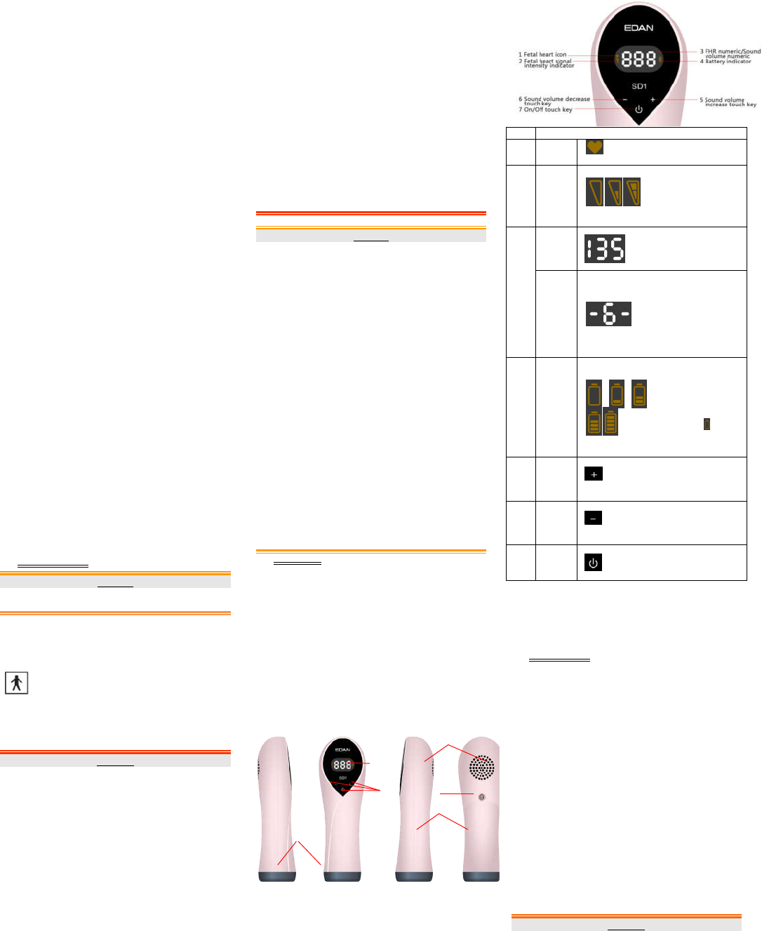
LCD Display& Touch Keys
Item
1
2
3
4
5
6
7
Battery
SD1 is powered by two AA alkaline batteries.
AA, 1.5 V;
Note:
You can use AA alkaline batteries of the same specification purchased
locally.
Basic Operation
NOTE:
To ensure that
Chapter
Safety Precautions
connecting all the components.
Opening the Package and Checking
Open the package; take out the Doppler and accessories carefully. Ke
package for possible future transportation or storage. Check the
components according to the packing list.
Check for any mechanical damage.
Check all the cables and accessories.
If there is any problem, contact us or your local distributor immediate
Installing the Battery
a) U
nscrew the screw
compartment
b)
Insert the battery into the compartment
cathode
compartment.
c)
Install the compartment cov
Removing/ Replacing the Battery
a)
Unscrew the screw with a cross screwdriver and remove the battery
compartment cover
b)
Take out the used battery. You can also replace it with a new one.
Ensure the new battery’s terminals are placed in the right direction as
indicated by the anode and cathode marks.
c)
Install the compartment cover and secure it with the screw.
1
Turn off the Doppler before
2
Replace
provided by the manufacturer or purchased locally.
Product Specifications
3
If the batteries have been inserted incorrectly, the Doppler will not
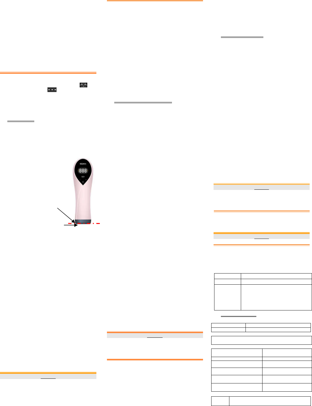
Ultrasonic Transducer Head
LCD Screen
Touch Keys
Loudspeaker
Screw
Battery Compartment Cover
Description
Fetal
heart
icon
Indicates fetal heart beat and flickers to the
fetal heart beat.
Fetal
heart
signal
intensity
indicator
This indicator displays on
the left side of the screen
and has three status: empty,
half empty and full, which
respectively represents low,
medium and high fetal
heart signal intensity.
FHR
numeric
Displays fetal heart rate
within the range from 50 bpm
to 240 bpm. When fetal heart
rate is out of the range, it
displays “---”.
Sound
volume
numeric
Sound volume numeric is
displayed in the center of the
screen, the same area as the
FHR numeric. When you
adjust sound volume, the
sound volume numeric will
display for 0.5 second before
switching back to display
FHR numeric. Sound volume
ranges from level 0 to 7.
Battery
indicator
Battery indicatordisplays
on the right side of the
screen. There are 5
battery levels,
represented by 0 to 4
panes in the icon. When
battery is empty, battery
empty icon will be
displayed and flickering,
and the battery needs
replacing.
Sound
volume
increase
touch
key
Touch the keyfor a little while to increase
sound volume.
Sound
volume
decrease
touch
key
Touch the key for a little while to decrease
sound volume.
On/Off
touch
key
When the Doppler is off, touch this key
for a little while to switch it on;
When the Doppler is on, touch this key
for a little while to switch it off.
SD1 is powered by two AA alkaline batteries.
Battery specification: LR6,
AA, 1.5 V;
You can use AA alkaline batteries of the same specification purchased
Basic Operation
To ensure that
the Doppler works properly, please read this chapter and
Safety Precautions
before operation; follow the steps when
connecting all the components.
Opening the Package and Checking
Open the package; take out the Doppler and accessories carefully. Ke
ep the
package for possible future transportation or storage. Check the
components according to the packing list.
Check for any mechanical damage.
Check all the cables and accessories.
If there is any problem, contact us or your local distributor immediate
ly.
Installing the Battery
nscrew the screw
with a cross screwdriver and remove the battery
compartment
cover.
Insert the battery into the compartment
carefully. Ensure its anode and
cathode
terminals are aligned with the anode and cathode marks on the
compartment.
Install the compartment cov
er and secure it with the screw.
Removing/ Replacing the Battery
Unscrew the screw with a cross screwdriver and remove the battery
compartment cover
.
Take out the used battery. You can also replace it with a new one.
Ensure the new battery’s terminals are placed in the right direction as
indicated by the anode and cathode marks.
Install the compartment cover and secure it with the screw.
WARNING
Turn off the Doppler before
removing or replacing the battery.
Replace
alkaline batteries with those of identical specifications
provided by the manufacturer or purchased locally.
SeeChapter
Product Specifications
for details about battery specifications.
If the batteries have been inserted incorrectly, the Doppler will not
function or it will be damaged.
4 Do not disassemble or short-circuit batteries.
5 Do not recharge batteries.
6 Do not dispose of batteries in fire or water.
7 Do not allow metal objects to contact the battery terminals.
8 Do not mix with used or other battery type (such as alkaline with
carbon zinc).
9 Do not solder the batteries directly. If soldering or welding
connection to the battery is required, consult our engineer for proper
methods.
10 Do not over-discharge batteries.
11 To install or remove batteries, follow the equipment manufacturer’s
instructions.
12 Keep battery away from small children. If swallowed, consult a
physician at once.
13 Store the battery in cool, dry place before use.Do not keep batteries
at temperature of 45°C or above, or at humidity of 75% or above.
14 Dispose the battery according to the local regulations. Refer to
IEC61429 for standard disposal when necessary.
Switching On
Touch the On/Off touch key for about 1second when the Doppler is off,
and the Doppler will display the switching on interface before
switching to display the test interface .
Switching Off
Touch the On/Off touch key for about 1second when the Doppler is on,
and the Doppler will be switched off.
If the Doppler is not in operation or no signal is received for 2 minutes, the
Doppler will switch off automatically.
FHR Monitoring
Before applying the Doppler to inspect FHR, you should always check
whether the Doppler is in good condition and whether there is evident
damage that might affect patient’s safety and the device’s function.If
evident damage is found, stop using it at once and replace it with a good
one.
Procedures to Monitor FHR:
a) Have the patient lie on her back.
b) Apply appropriate
amount of coupling gel
to the ultrasonic
transducer head of the
Doppler and switch on
the Doppler.
c) Palpate the patient’s
abdomen gently to
confirm the fetus’s
position.
d) Place the Doppler on
the patient’s abdomen,
and move it around the
fetus’s position or tilt it
until a clear and
rhythmic heart sound is
heard and FHR numeric is stably displayed.
Note:
1 Do not mistake the maternal heart rate for fetal heart rate.Do not
mistake the maternal heart rate for fetal heart rate. The fetal pulse
should be different from the maternal pulse, which can be measured at
the wrist or neck.
2 Do not wear gloves to touch the keys. If there's water and coupling gel
on the fingers, please clean them first or the touching effect will be
influenced.
How to Find the Best FH Signal:
1) The easiest way: take the position the doctor last monitored for FHR
as a reference and move the Doppler around the position slowly
until the best FH signal is found.
2) The fetal heart position may change as the fetus moves inside the
uterus. You can confirm the fetal position first according to the
position of the uterus fundus in different gestational weeks.
The clearest and loudest fetal heart sound is generally obtained
when the Doppler is placed on the fetus’s back. Fetal movement is
usually the movement of fetal limbs. So, if frequent fetal movement
occurs at the right side of the abdomen, the fetus’s back is
probablyat the left sideand vice versa.You can find the fetus’s back
according to fetal movement’s position.
If the fetus is in cephalic delivery position, the fetal heart is either on
the right side or on the left side below the navel; if the fetus is in
breech delivery position, the fetal heart is either on the right side or
on the left side above the navel.
Steps to Find Fetal Heart:
Have the patient lie on back and relax >> confirm fetal position by hand >>
apply coupling gel to the Doppler>> place the Doppler on patient’s
abdomen and start looking for the fetal heart >> the fetal heart is found
when the Doppler gives out a continuing thumping sound
“boom-boom-boom”.
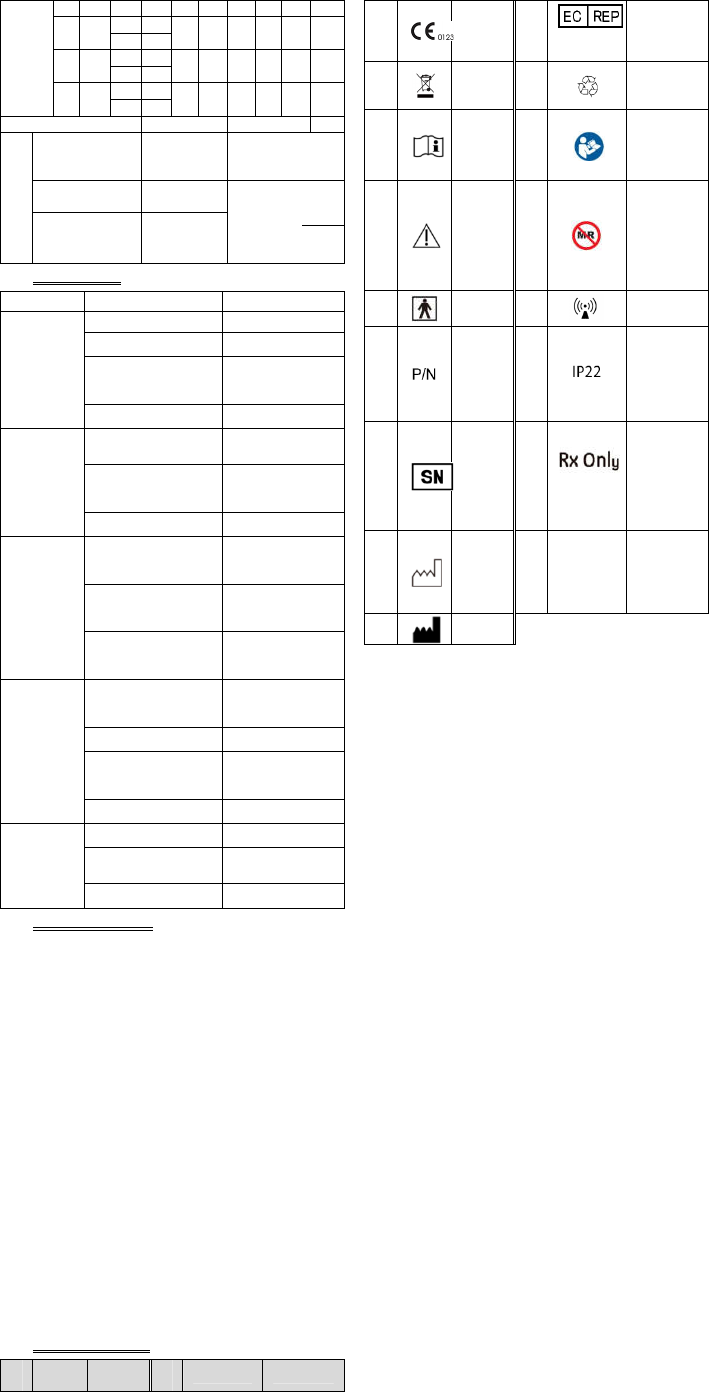
CAUTION
1 The Doppler’s degree of protection against harmful ingress of water
is IP22. Do not immerse it in water.
2 The Doppler is delicate and sensitive. Please handle it with care and
try to avoid dropping on to the ground or any hard surfaces. Any
damage caused by dropping is not covered by the warranty.
3 Keep the coupling gel away from children. If swallowed, consult a
The coupling gel
should not exceed
this limit.
This area can
be immerged in
coupling gel
physician at once.
Note:
1 The best quality of fetal heart signal is obtained only when the Doppler
is placed in the best monitoring position.
2 Do not place the Doppler near positions where placental sound or
umbilical blood flow sound is loud.
3 If the fetus is in the cephalic position and the mother is supine, the
clearest heart sound will normally be found on the midline below the
navel. During monitoring, the pregnant woman’s prolonged lying in
the supine position should be avoided to reduce the possibility of
supine hypotension. Putting a pillow or cushion under the patient’s
head or feet can be of help.
4 It is not possible to obtain accurate FHR unless a clear fetal heart
signal is detected. If the calculated FHR is not in accordance with the
beat of the fetal heart sound, the fetal heart sound auscultation result
shall prevail.
5 When applied to the patient, the Doppler may warm slightly (less than
2°C (35.6°F) above ambient temperature). When NOT applied, the
Doppler may slightly (less than 5°C (41°F) above ambient
temperature).
After Monitoring
1) Switch off the Doppler.
2) Wipe the remaining gel off the patient and the probe with a clean soft
cloth or tissue.
Mobile Application Software (APP)
SD1 can connect to mobile phones with its Bluetooth function (optional).
The SD1 APP has both Android and iOS versions.
iOS APP operating environment: Android APP operating
environment:
A) hardware environment A) hardware environment
Processor: dual-core Apple A6 CPU: frequency≥1.0GHz
RAM: ≥1GB
RAM: ≥1GB
B) software environment: iOS
8.0 and above operating system
B)software environment: Android
4.3 and above operating system
C)network environment: support
Bluetooth
C)network environment: support
Bluetooth
How to use SD1 Medical APP
1.Download and install software
Scan either of the following QR codes to download the SD1Medical APP,
and install and run it as prompted.
TBC TBC
Note:
1 Your mobile phone may prohibit the
installation of “applications from
unknown sources”. Enter Settings to
allow the installation first.
2 For normal functioning of the APP,
please give the APP function-related
permissions.
3 For how to use the APP, read the
instructions in the About
sub-interface under the Settings
interface of the APP.
2.Activate the device
Open the APP and go to Settings>Activation and input SD1 activation
code (14 numbers after 01).
3.Pair device
Open Bluetooth function of the mobile to automatically pair the SD1.
4.Start detection
Put the coupling gel on SD1 and position the probe to the optimal place of
maternity's abdomen. And click the "start" key. After pressing start,
confirm that the data on the APP and the SD1 probe match. As with
any Bluetooth communication, it is important to make sure the
connection is not compromised.
5.Adjust the fetal heart beat sound volume
When using mobile phone to play the fetal heart beat sound, you can adjust
the volume with the volume keys of the mobile phone. When using SD1 to
play the heart beat sound, touch ‘volume+’ or ‘volume -’ to adjust the
volume.
6.Finish the monitoring
When the monitoring is finished, click ‘Stop’ touch key and the detection
data will be saved automatically.
Note:Please make sure your mobile phone has enough battery power,and
avoid killing the process directly or switching to other applications during
the fetal heart monitoring.
7.Real time detection mode and DEMO mode
We provide DEMO mode for users' reference. You can turn on DEMO key
in Setup and enter fetal heart monitoring interface to watch the DEMO.
The word ‘DEMO’ is displayed in the interface to distinguish from real
time detection.
WARNING
SD1 complies with Part 15 of the FCC Rules. Operation is subject to the
following two conditions:
1)this device may not cause harmful interference, and
2)this device must accept any interference received, including interference
that may cause undesired operation.
NOTE:
1.This equipment (SD1) has been tested and found to comply with the
limits for a Class B digital device, pursuant to part 15 of the FCC Rules.
These limits are designed to provide reasonable protection against harmful
interference in a residential installation. This equipment generates, uses
and can radiate radio frequency energy and, if not installed and used in
accordance with the instructions, may cause harmful interference to radio
communications. However, there is no guarantee that interference will not
occur in a particular installation. If this equipment does cause harmful
interference to radio or television reception, which can be determined by
turning the equipment off and on, the user is encouraged to try to
correctthe interference by one or more of the following measu
-
Reorient or relocate the receiving antenna.
-
Increase the separation betw
-
Connect the equipment into an outlet on a circuit different from that to
which the receiver is connected.
-
Consult the dealer or an experienced
2.
Any changes or modifications to this unit not expressly approved by the
party responsible for compliance could void the user's authority to operate
the equipment.
Maintenance and Cleaning
Maintenance
Before each use, c
that may affect the patient and the operator’s safety or the Doppler’s
functioning. If the damage is evident,
or replace it.
The overall check of the Doppler, including sa
check, should be performed by qualified personnel every 12 months, and
each time after service.
and insulation test.
regulations on
The accuracy of FHR is determined by the Doppler and cannot be adjusted
by user. If you have doubt concerning the accuracy of FHR,
other methods such as using a stethoscope, or contact local distributor or
the
manufacturer for help.
The Doppler is frangible and must be handled with care.Wipe the
remaining gel off the Dopplerafter each use. These measures can help
prolong the Doppler’s life.
Replace the accessories such as the battery according to use. If any of
accessories are damaged, refer to chapter
details and order new ones.
Please check the label for the date of manufacture, the service life is 5
years ( The service life is limited to the Doppler, not including the
replaceable a
The frequency of usage is 8 hours/day).
Cleaning
Before cleaning, switch off the Doppler.
Keep the exterior surface of the device clean and free of dust and dirt.
Clean the exterior surface of
clean it using a soft cloth dampened with mild near neutral detergent,
ethanol (75%) or isopropanol (70%),
immediately.
1
Do not use strong solvent, such as
2
Never use an abrasive such as steel wool or metal polish.
3
The Doppler’s degree of protection against harmful ingress of water is
IP22. Do not immerse it in water.
4
Do not remain any solution on the surface after cleaning.
Disinfection
In normal use
soiled, clean the main unit case and then disinfect it by wiping it with a
soft cloth dampened with
it dry with a dry cloth.
Do not immerse the D
Sterilization
Do not sterilize the Doppler
NOTE:
After cleaning or disinfection, check if the op
problem is detected, please contact the manufacturer for service before
reusing it.
Checking Item
Visual Check
Functional
Check
Product Specifications
Product Information
Product Name
Model
Complied Standards
IEC
60601
60601-1
-
Classification
Anti-
electric Shock Type:
Anti-electric Shock Degree:
Degree of Protection against
Harmful Ingress of Water:
Degree of Safety in Presenceof
Flammable Gases:
Working System:
EMC:
Physical Specifications
Size:
correctthe interference by one or more of the following measu
res:
Reorient or relocate the receiving antenna.
Increase the separation betw
een the equipment and receiver.
Connect the equipment into an outlet on a circuit different from that to
which the receiver is connected.
Consult the dealer or an experienced
radio/TV technician for help.
Any changes or modifications to this unit not expressly approved by the
party responsible for compliance could void the user's authority to operate
the equipment.
Maintenance and Cleaning
Maintenance
Before each use, c
heck if the equipment has visible evidence of damage
that may affect the patient and the operator’s safety or the Doppler’s
functioning. If the damage is evident,
contact the manufacturer for service
or replace it.
The overall check of the Doppler, including sa
fety check and function
check, should be performed by qualified personnel every 12 months, and
each time after service.
And safety check must include current leakage test
and insulation test.
Besides the above requirements, comply with local
regulations on
maintenance and measurement.
The accuracy of FHR is determined by the Doppler and cannot be adjusted
by user. If you have doubt concerning the accuracy of FHR,
verify it with
other methods such as using a stethoscope, or contact local distributor or
manufacturer for help.
The Doppler is frangible and must be handled with care.Wipe the
remaining gel off the Dopplerafter each use. These measures can help
prolong the Doppler’s life.
Replace the accessories such as the battery according to use. If any of
the
accessories are damaged, refer to chapter
Ordering Information for
details and order new ones.
Please check the label for the date of manufacture, the service life is 5
years ( The service life is limited to the Doppler, not including the
replaceable a
ccessories. The only replaceable accessory of SD1 is battery.
The frequency of usage is 8 hours/day).
Cleaning
Before cleaning, switch off the Doppler.
Keep the exterior surface of the device clean and free of dust and dirt.
Clean the exterior surface of
the Doppler with a dry, soft cloth. If necessary,
clean it using a soft cloth dampened with mild near neutral detergent,
ethanol (75%) or isopropanol (70%),
and then wipe it dry with a dry cloth
immediately.
CAUTION
Do not use strong solvent, such as
acetone.
Never use an abrasive such as steel wool or metal polish.
The Doppler’s degree of protection against harmful ingress of water is
IP22. Do not immerse it in water.
Do not remain any solution on the surface after cleaning.
Disinfection
In normal use
theDoppler does not need disinfection. In case of being
soiled, clean the main unit case and then disinfect it by wiping it with a
soft cloth dampened with
ethanol (75%) or isopropanol (70%). Then wipe
it dry with a dry cloth.
CAUTION
Do not immerse the D
oppler into the disinfector.
Sterilization
Do not sterilize the Doppler
.
After cleaning or disinfection, check if the op
Dpler functions well. If any
problem is detected, please contact the manufacturer for service before
reusing it.
Checking Item
Method
Visual Check
Inspect the Doppler for any damage.
Functional
Check if the Doppler can be switched on and off
normally (see Switching On and Switching
Off).When the Doppler is switched on, check if the
display panel works as described in LCD
Display&Touch Keys; touch the ultrasonic
transducer head gently with your hand and check if
the Doppler gives out sound normally.
Product Specifications
Product Information
Product Name
Ultrasonic Pocket Doppler
SD1
Complied Standards
60601
-1:2005/A1:2012, EN 60601-1:2006/A1:2013, IEC
2:2014, IEC 60601-2-37:2015,IEC 61266:1994
Classification
electric Shock Type:
Internally powered equipment
electric Shock Degree:
Type BF equipment
Degree of Protection against
Harmful Ingress of Water:
IP22. Do not immerse it in water.
Degree of Safety in Presenceof
Flammable Gases:
Equipment not suitable for use in
presence of flammable gases
Working System:
Continuous running equipment
CISPR 11 Group 1 Class B
Physical Specifications
Length*Width* Height: (48±2) mm× (39±2) mm× (147±3)
mm

Weight: < 180g
LCD:
Size: (24±2) mm× (13±2) mm
Display:
◆FHR
◆Battery level
◆Signal intensity
◆Sound volume
level
◆FH icon
Coupling
Gel:
pH: 5.5~8.0
Acoustic Impedance: 1.5x10⁶ Pa.s/m ~1.7x10⁶Pa.s/m
(35°C/95ºF)
Environment
Working:
Temperature:+5°C ~ +40°C ( +41ºF ~ +104ºF)
Humidity:15% RH ~ 95% RH(non-condensing)
Atmospheric Pressure:70kPa ~ 106 kPa
Transport and
Storage:
Temperature:-25°C ~ +70°C (-13ºF ~ +158ºF)
Humidity:15% RH ~ 95% RH (non-condensing)
Atmospheric Pressure:70 kPa ~106 kPa
Performance Specifications
FHR (Essential
Performance):
FHR Measuring Range: 50 bpm ~ 240 bpm
Accuracy: ±2 bpm
Note: FHR measurement result may not be
accurate if the equipment is measuring beyond its
measuring range.
FHR Resolution:
1bpm
Audio Output:
Output Power: 2w
Background noise: <45dBA
Overall Sensitivity:
>110dB
Auto Power-off:
Power off when the Doppler receives no signal or
operation for 2 minutes.
Bluetooth:
TransmissionRange (Without Obstacles) :>5m
(Indoor range depends on the building’s structure
and material.)
Ultrasound:
Nominal Frequency: 3MHz
Working Frequency: 3MHz
p_<1 MPa
Iob<10 mW/cm2
Ispta<100 mW/cm2
Isata<10 mW/cm2
Isppa.3<190 W/cm2
Ispta.3<94 mW/cm2
Effective Radiating Area: 490mm2 ± 15%
Working Mode: pulse wave
Battery Specifications
Specification: Two AA 1.5V alkaline batteries (AA, LR6, 1.5V)
Working Duration: ◆≥6h
Bluetooth Specifications
FCC ID SMQSD1MEDAN
Modulation: GFSK π /4-DQPSK 8DPSK
Frequency: 2400-2483.5MHz
Tolerance Frequency: ≤ 20ppm
RF output power: ≤ 20dBm (EIRP)
Occupied Channel Bandwidth: ≤ 2MHz
Transmitter Unwanted Emissions: ≤﹣30dBm
Low OutputSummary Table
(For systems whose global maximum valuedoes not exceed 1.0)
System: SD1 Ultrasonic Pocket Doppler
Model
(MHz)
Ispta.3
(mW/cm2)
TI
Type
TI
Value MI Isppa.3
(W/cm2)
SD1
CD3.0 5.69 TIS 0.05 0.01 0.02
TIB
0.01
Ordering Information
CAUTION
Only the parts supplied by the manufacturershould be used with the
Doppler.
Parts Part Number
Main Unit
SD1
Doppler(Non-Bluetooth
version)
02.06.262535
SD1 Doppler(Bluetooth
version) 02.06.262639
Accessories
AA Alkaline Battery 01.21.064086
Normal Carry Case
01.56.465616
Coupling Gel 01.57.078170
Ultrasound Intensity and Safety
Ultrasound in Medicine
The use of diagnostic ultrasound has proved to be a valuable tool in
medical practice. Given its known benefits for non-invasive investigations
and medical diagnosis, including investigation of the human fetus, the
question of clinical safety with regards to ultrasound intensity arises.
There is no easy answer to the question of safety surrounding the use of
diagnostic ultrasound equipment. Application of the ALARA (As Low As
Reasonably Achievable) principle serves as a rule-of-thumb that will help
you to get reasonable results with the lowest possible ultrasonic output.
The American Institute of Ultrasound in Medicine (AIUM) states that
given its track record of over 25 years of use and no confirmed biological
effects on patients or instrument operators, the benefits of the prudent use
of diagnostic ultrasound clearly outweigh any risks.
Ultrasound Safety and the ALARA Principle
Ultrasound waves dissipate energy in the form of heat and can therefore
cause tissue warming. Although this effect is extremely low with Doppler,
it is important to know how to control and limit patient exposure. Major
governing bodies in ultrasound have issued statements to the effect that
there are no known adverse effects from the use of diagnostic
ultrasound,however, exposure levels should always be limited to As Low
As Reasonably Achievable (the ALARA principle).
Explanation of MI/TI
MI (Mechanical Index)
Cavitations will be generated when ultrasound wave passes through and
contacts tissues, resulting in instantaneous local overheating. This
phenomenon is determined by acoustic pressure, spectrum, focus,
transmission mode, and factors such as states and properties of the tissue
and boundary. This mechanical bioeffect is a threshold phenomenon that
occurs when a certain level of ultrasound output is exceeded. The threshold
is related to the type of tissue. Although no confirmed adverse mechanical
effects on patients or mammals caused by exposure at intensities typical of
present diagnostic ultrasound instruments have ever been reported, the
threshold for cavitation is still undetermined. Generally speaking, the
higher the acoustic pressure, the greater the potential for mechanical
bioeffects; the lower the acoustic frequency, the greater the potential for
mechanical bioeffects.
The AIUM and NEMA formulate mechanical index (MI) in order to
indicate the potential for mechanical effects. The MI is defined as the ratio
of the peak-rarefactional acoustic pressure (should be calculated by tissue
acoustic attenuation coefficient 0.3 dB/cm/MHz) to the acoustic frequency.
MI = Pr, α
fawf ×CMI
CMI = 1 (MPa / MHz )
TI (Thermal Index)
Heating of tissues is caused by absorption of ultrasound when the
ultrasound energy is applied. The temperature rise is determined by the
acoustic intensity, exposed area and thermo physical properties of the
tissue.
In order to indicate the potential for temperature rise caused by thermal
effects, the AIUM and NEMA formulate thermal index (TI). It is defined
as the ratio of the total acoustic power to the acoustic power required to
raise the tissue temperature by 1ºC (1.8°F).
According to different thermo physical properties of the tissue, TI is
divided into three kinds: TIS, TIB and TIC.
TIS (Soft Tissue Thermal Index): It provides an estimate of potential
temperature rise in soft or similar tissues.
TIB (Bone Thermal Index): It provides an estimate of potential
temperature rise when the ultrasound beam passes through soft tissue and a
focal region is in the immediate vicinity of bone.
TIC (Cranial Bone Thermal Index): It provides an estimate of potential
temperature rise in the cranial bones or superficial bones.
Measurement Uncertainties
The uncertainties in the measurements were predominantly systematic in
origin; the random uncertainties were negligible in comparison. The
overall systematic uncertainties were determined as follows:
1. Hydrophone Sensitivity: ± 12percent for intensity, ± 6 percent for
pressure. Based on the hydrophone calibration report by ONDA. The
uncertainty was determined within ±1 dB in frequency range 1-15 MHz.
2. Digitizer: ±0.3 percent for intensity. ± 0.15 percent for pressure.
Based on the stated accuracy of the 8-bit resolution of the Agilent
DSO6012 Digital Oscilloscope and the signal-to-noise ratio of the
measurement.
3. Temperature:±2.4 percent for intensity uncertainty, ±1.2 percent for
pressure uncertainty.
Based on the temperature variation of the water bath of ± 1ºC (1.8°F).
4. Spatial Averaging: ± 3.5 percent for intensity, ± 1.75percent for
pressure.
5. Non-linear Distortion: N/A.
No effects of nonlinear propagation were observed.
Since all the above error sources are independent, they may be added
on an RMS basis, giving a total uncertainty of ± 12.73 percent for all
intensity values reported, ± 6.37 percent for all the pressure values,,± 12.6
percent for the Mechanical Index, uncertainty of ±12.73% percent for
power,±0.15 percent for center frequency, ±6.87%for the MI.
Prudent Use Statement
Although no confirmed bioeffects on patients caused by exposure from
present diagnostic ultrasound equipment have ever been reported, the
potential exists that such bioeffects may be identified in the future.
Therefore, the ultrasound should be used prudently. High levels of acoustic
output and long exposure time should be avoided while acquiring
necessary clinical information.
Reference for Acoustic Output and Safety
1. “Bioeffects and Safety of Diagnostic Ultrasound” issued by AIUM in
1993
2. “Medical Ultrasound Safety” issued by AIUM in 1994
3. "Acoustic Output Measurement Standard for Diagnostic Ultrasound
Equipment,
Revision 3" issued by AIUM/NEMA in 2004
4. "Standard for real-time display of thermal and mechanical acoustic
output indices on
diagnostic ultrasound equipment, Revision 2" issued by AIUM/NEMA in
2004
5. "Information for Manufacturers Seeking Marketing Clearance of
Diagnostic
Ultrasound Systems and Transducers" issued in 2008.
6. “Medical electrical equipment—Part 2-37: Particular requirements for
the basic safety and essential performance of ultrasonic medical diagnostic
and monitoring equipment" issued by IEC in 2007.
Acoustic Output Reporting Table for Track 1 Acoustic output
reporting table for IEC60601-2-37(IEC60601-2-37, Edition 2.1, 2015-0,
table 201.103)
Transducer Model: SD1, Operating Mode: PW mode
Index label
MI
TIS
TIB
TI
C
At
Surf
ace
Bel
ow
Surf
ace
At
surf
ace
Bel
ow
Surf
ace
Maximum index
value
0.0
1
0.05 0.01
N/
A
Index component
value
N/A 0.05 NA 0.01
Acoust
ic
Param
eters
pr.αat
zMI
(MPa)
0.0
2
P
(mW)
7.35 7.35
N/
A
P1x1
(mW)
N/A N/A
zs(cm)
3.50
zb(cm)
3.70
zMI(cm)
3.7
0
zPII.α
(cm)
.α
3.7
0
fawf
(MHz)
3.0
0
3.00 3.00
N/
A
Other
inform
ation
prr
(Hz)
50
00
srr(Hz)
N/
A
npps
1
Ipa.α at
zPII.α
(W/cm2)
0.0
2
Ispta.α at
zPII.α or
zSII.α(m
W/cm2)
5.6
9
Ispta at
zPII or
zSII
(mW/cm2
)
12.
26
pr. at
zPII
(MPa)
0.0
4
Operating control
conditions
Fixed
Acoustic Output Reporting Table for Track1(Non-autoscanning
Mode)
Transducer Model: SD1 ,Operating Model: PW
Acoustic Output MI
ISPTA.3
(mW/cm^
2)
ISPPA.3
(W/cm^2
)
Global Maximum Value
0.01
5.69
0.02
Associate
d
Acoustic
Paramete
r
Pr.3
(MPa)
0.02
W0
(mW)
7.35
8.97
fc
(MHz)
3.00
3.00
3.00
Zsp
(cm)
3.70
3.70
3.70
Beam
dimension
s
X-6
(cm
)
2.50
2.50
Y-6
(cm
)
2.50
2.50
PD
(usec)
72.2
5
72.25
PRF
(Hz)
5000
5000
EBD
Az.
(cm
)
2.50
Ele.
(cm
)
2.50
Operating
Control
Condition
s
Fixed
Standard Parameter Equal Contrast List
IEC60601-2-37 Standard Parameters
Paramete
r
Note
Paramete
r
Note
pr.α
Attenuated
Peak-rare-factiona
l Acoustic
Pressure
fawf
Center
Frequency,
Acoustic
Working
Frequency
pr
Peak-rare-factiona
l Acoustic
Pressure
X -12dB Output
Beam
Dimensions
P Output Power
Y
zs
Depth for Soft
Tissue Thermal
Index
td Pulse
Duration
Pα(Zs) Attenuated Output
Power
prr
Pulse
Repetition
Frequency
(Pulse

Repetition
Rate)
Ita.α(Zs)
Attenuated
Temporal-average
Intensity
deq
Equivalent
Beam
Diameter
zbp Break-point Depth
Ipi.α at max
MI
Attenuated
Pulse-averag
e Intensity at
the point of
Maximum
MI
zb
Depth for Bone
Thermal Index
Aaprt
-12dB Output
Beam Area
Ipi.α
Attenuated
Pulse-intensity
Integral
MI Mechanical
Index
Ipi Pulse-intensity
Integral
TIS
Soft Tissue
Thermal
Index
deq(Zb)
Equivalent Beam
Diameter at the
point of Zsp
TIB
Bone
Thermal
Index
TIC
Cranial-bone
Thermal
Index
EMC Information
Electromagnetic Emissions
Guidance and manufacturer’s declaration – electromagnetic
emission
The SD1 Ultrasonic Pocket Doppler is intended for use in the
electromagnetic environment specified below. The customer or the
user of the device should assure that it is used in such an environment.
Emission test Compliance
Electromagnetic
environment - guidance
RF emissions
CISPR 11 Group 1
The SD1Ultrasonic Pocket
Doppler uses RF energy only
for its internal function.
Therefore, its RF emissions
are very low and are not
likely to cause any
interference in nearby
electronic equipment.
RF emission
CISPR 11
Class B The SD1 Ultrasonic Pocket
Doppler is suitable for use in
all establishments, including
domestic establishments and
those directly connected to
the public low-voltage power
supply network that supplies
buildings used for domestic
purposes.
Harmonic
emissions
IEC/EN61000-3-2
Not
applicable
Voltage
fluctuations
/flicker emissions
IEC/EN61000-3-3
Not
applicable
Electromagnetic Immunity
Guidance and manufacture’s declaration–electromagnetic immunity
The SD1 Ultrasonic Pocket Doppler is intended for use in the
electromagnetic environment specified below. The customer or the user of
the device should assure that it is used in such an environment.
Immunity test IEC 60601 test
level
Complia
nce level
Electromagnetic
environment-gui
dance
Electrostatic
discharge
(ESD)
IEC 61000-4-2
8kV contact
15kV air
8kV
contact
15kV air
Floors should be
wood, concrete or
ceramic tile. If
floor are covered
with synthetic
material, the
relative humidity
should be at least
30%.
Electrical Fast
Transient/Burst
IEC/EN61000-
4-4
±2kV forpower
supplylines
±1kV
forinput/output
lines
Not
applicabl
e
Not applicable
Surge
IEC/EN61000-
4-5
± 1 kV line(s)
toline(s)
± 2 kV line(s)
to earth
Not
applicabl
e
Not applicable
Voltage dips,
short
interruptions,
and
voltage
variations
on power
supply
input lines
IEC/EN61000-
4-11
<5%UT(>95%
dip inUT)
for 0.5cycle
40%UT(60%di
p in UT)
for5 cycles
70%UT(30%di
p in UT)
for25 cycles
<5%UT(>95%
dip inUT)
for 5s
Not
applicabl
e
Not applicable
Power
frequency
(50Hz/60Hz)
magnetic field
IEC61000-4-8
30 A/m 30 A/m
Power frequency
magnetic fields
should be at levels
characteristic of a
typical location in
a typical
commercial or
hospital
environment.
Electromagnetic Immunity
Guidance and manufacture’s declaration – electromagnetic immunity
The SD1 Ultrasonic Pocket Doppler is intended for use in the
electromagnetic environment specified below. The customer or the user of
the device should assure that it is used in such an environment.
Immunity
test
IEC
60601
test level
Complianc
e level
Electromagnetic
environment-guidanc
e
Conducted
RF
IEC61000-4-
6
Radiated RF
IEC61000-4-
3
3 Vrms
150 kHz
~ 80 MHz
6Vrmsc)i
n ISM
bands
between
0,15 MHz
and80
MHz
10V/m
80 MHz ~
2.7 GHz
3 Vrms
150 kHz to
80 MHz
6Vrmsc)in
ISM bands
between
0,15 MHz
and 80 MHz
10 V/m
80 MHz to
2.7 GHz
Portable and mobile
RF communications
equipment should be
used no closer to any
part of the SD1
Ultrasonic Pocket
Doppler, including
cables, than the
recommended
separation distance
calculated from the
equation applicable to
the frequency of the
transmitter.
Recommended
separation distance:
Pd 2.1150 kHz
to 80 MHz
Pd 2.1
80
MHz to 800 MHz
Pd 3.2 800
MHz to 2.7 GHz
d=6 /E at RF
wireless
communications
equipment bands
(Portable RF
communications
equipment (including
peripherals such as
antenna cables and
external antennas)
should be used no
closer than 30 cm (12
inches) to any part of
the SD1 Ultrasonic
Pocket Doppler,
including cables
specified by the
manufacturer).
Where P is the
maximum output
power rating of the
transmitter in watts
(W) according to the
transmitter
manufacturer and d is
the recommended
separation distance in
metres (m).
Field strengths from
fixed RF transmitters,
as determined by an
electromagnetic site
survey,a should be less
than the compliance
level in each frequency
range.b
Interference may occur
in the vicinity of
equipment marked
with the following
symbol:
NOTE1:At 80 MHz and 800 MHz, the higher frequency range applies.
NOTE2: These guidelines may not apply in all situations. Electromagnetic
propagation is affected by absorption and reflection from structures,
objects and people.
a
Field strengths from fixed transmitters, such as base stations for radio
(cellular/cordless) telephones and land mobile radios, amateur radio,
AM and FM radio broadcast and TV broadcast cannot be predicted
theoretically with accuracy. To assess the electromagnetic environment
due to fixed RF transmitters, an electromagnetic site survey should be
considered. If the measured field strength in the location in which the
SD1 Ultrasonic Pocket Doppler is used exceeds the applicable RF
compliance level above, the SD1Ultrasonic Pocket Doppler should be
observed to verify normal operation. If abnormal performance is
observed, additional measures may be necessary, such as reorienting or
relocating the SD1 Ultrasonic Pocket Doppler.
b Over the frequency range 150 kHz to 80 MHz, field strengths should be
less than 3 V/m.
c The ISM (industrial, scientific and medical) bands between 0,15 MHz
and 80 MHz are 6,765 MHz to6,795 MHz; 13,553 MHz to 13,567 MHz;
26,957 MHz to 27,283 MHz; and 40,66 MHz to 40,70 MHz. The
amateur radio bands between 0,15 MHz and 80 MHz are 1,8 MHz to 2,0
MHz, 3,5 MHz to 4,0 MHz, 5,3 MHz to 5,4 MHz, 7 MHz to 7,3 MHz,
10,1 MHz to 10,15 MHz, 14 MHz to 14,2 MHz, 18,07 MHz to 18,17
MHz,21,0 MHz to 21,4 MHz, 24,89 MHz to 24,99 MHz, 28,0 MHz to
29,7 MHz and 50,0 MHz to 54,0 MHz.
Table-Test specifications for ENCLOSURE PORT IMMUNITY to RF
wireless communications equipment
Test
Freq
uenc
y
(MH
z)
Bran
d a)
(MH
z)
Service
a)
Modu
lation
b)
Maxi
mum
Powe
r(W)
Dist
ance
(m)
IMM
UNIT
Y
TEST
LEVE
L
(V/m)
385
380-
390
TETRA
400
Pulse
modul
1.8 0.3 27
ationb)
18Hz
450 430-
470
GMRS
460,
FRS 460
FM C)
±5
kHz
deviati
on
1kHz
sine
2 0.3 28
710
704-
787
LTE
Brand
13, 17
Pulse
modul
ationb)
217
Hz
0.2 0.3 9
745
780
810
800-
960
GSM
800/900,
TETRA
800,iDE
N 820,
CDMA
850,
LTE
Band 5
Pulse
modul
ationb)
18 Hz
2 0.3 28
870
930
1720
1700
-199
0
GSM
1800;
CDMA
1900;
GSM
1900;
DECT;
LTE
Band 1,
3,
4,25;U
MTS
Pulse
modul
ationb)
217
Hz
2 0.3 28
1845
1970
2450
2400
-257
0
Bluetoot
h,
WLAN,
802.11
b/g/n,
RFID
2450,
LTE
Brand 7
Pulse
modul
ationb)
217
Hz
2 0.3 28
5240
5100
-580
0
WLAN
802.11
a/n
Pulse
modul
ationb)
217
Hz
0.2 0.3 9
5500
5785
Note: If necessary to achieve the IMMUNITY TEST LEVEL, the distance
between the transmitting antenna and the ME EQUIPMENT or ME
SYSTEM maybe reduce to 1m. The 1 m test distance is permitted by IEC
61000-4-3.
a) For some services, only the uplink frequencies are included.
b) The carrier shall be modulated using a 50% duty cycle square wave
signal.
c) As an alternative FM modulation, 50% pulse modulation at 18 Hz may
be used because while it does not represent actual modulation, it would be
worst case
Recommended Separation Distances
Recommended separation distances between portable
and mobile RF communications equipment and the SD1
Ultrasonic Pocket Doppler
The SD1 Ultrasonic Pocket Doppleris intended for use in an
electromagnetic environment in which radiated RF disturbances are
controlled. The customer or the user of theSD1 Ultrasonic Pocket
Doppler can help prevent electromagnetic interference by maintaining
a minimum distance between portable and mobile RF
communications equipment (transmitters) and the SD1 Ultrasonic
Pocket Doppleras recommended below, according to the maximum
output power of the communications equipment.
Rated
maximum
output
power of
transmitter
(W)
Separation distance according to frequency of
transmitter (m)
150 kHz to
80 MHz
Pd 2.1
80 MHz to
800 MHz
Pd 2.1
800 MHz to
2.7GHz
Pd 3.2
0.01 0.12 0.12 0.23
0.1 0.38 0.38 0.73
1 1.2 1.2 2.3
10 3.8 3.8 7.3
100 12 12 23
For transmitters rated at a maximum output power not listed above,
the recommended separation distance d in meters (m) can be
estimated using the equation applicable to the frequency of the
transmitter, where P is the maximum output power rating of the
transmitter in watts (W) according to the transmitter manufacturer.
NOTE 1: At 80 MHz and 800 MHz, the separation distance for the
higher frequency range applies.
NOTE 2: These guidelines may not apply in all situations.
Electromagnetic propagation is affected by absorption and reflection
from structures, objects and people.
Overall Sensitivity
D d
A B V
S
V
n C S
∑Ba B
B
1.58
3MHz
5
0
4
0.
9
T 5
#
0
7
7.
0
1
4
0
7
5
5.
4
2
12
3.
32
B
7
7.
7
5
4
4.
4
T 5
#
0
6
8.
4
8
0
4
0
6.
0
2
11
8.
82
B
6
8.
1
0
0
4
6.
9
T 5
#
0
6
9.
6
1
8
0
9
0
6.
0
2
12
2.
52
B
6
9.
2
0
0
5
2.
9
T 5
#
0
6
8.
4
8
3
4
2
5.
9
2
12
7.
22
B
7
5.
2.38 5 3 T 5
#
0
7 1 6 5. 12
3MHz 0
9.
0
B
7
7.
7.
0
3
0
9
5
0
1.
50
7
5
4
2.
5
T 5
#
0
7
7.
0
1
1
5
5
5
6.
4
1
12
5.
91
B
7
7.
1
0
0
4
5.
0
T 5
#
0
6
8.
4
1
3
0
6
5
6.
0
2
11
9.
42
B
6
8.
2
0
0
5
1.
0
T 5
#
0
7
7.
0
7
8
4
3
5.
1
7
13
3.
17
B
7
5.
Doppler Frequency (Hz) 505 Velocity of
Target (cm/s)
10
N
ot
e
D: Diameter
ofTarget
Reflector(mm)
A: Attenuation
A(dB))
S:Overall Sensitivity
(S=A+B+C)dB
d: Distance (d)(mm) VS: Signal
RMS (mV)
C:Signal to Noise
Ratio (dB)
...
...
log20 10 smrV
smrV
C
n
s
B:Two-wayAttenuat
ion(dB)
B=∑Ba+Bw
Vn: Noise
RMS (mV)
Troubleshooting
Problem Possible Cause Solution
Fail to power
on, or shut
down shortly
after
switching on
Battery level is very low. Replace the battery.
Battery is not installed
properly.
Re-install the battery.
Fail to switch on the
Doppler as instructed.
Touch the On/Off
touch key for a while
to power on the
Doppler.
The Doppler has
malfunctions.
Contact service
personnel.
Loudspeaker
does not
work.
Sound volume has been
turned down to the lowest
level.
Adjust sound volume
to appropriate level.
If the Doppler is
configured with Bluetooth,
fetal heart sound can be
played by mobile phone.
Set to play fetal heart
sound by mobile phone
or the Doppler on the
APP.
The Doppler has
malfunctions.
Contact service
personnel.
FHR cannot
be displayed
stably.
There is strong
interference source such as
high frequency machines
and mobile phones nearby.
Use the Doppler away
from strong
interference sources.
The fetal heart position
has changed because of
fetal movement.
Relocate the Doppler
to the best fetal heart
rate monitoring
position.
Friction between the
Doppler and patient’s
abdomen causes false
displaying.
Find the best fetal heart
rate monitoring
position.
Sensitivity is
low and noise
is too much.
There is strong
interference source such as
high frequency machines
and mobile phones nearby.
Use the Doppler away
from strong
interference sources.
The Doppler is not applied
with coupling gel.
Apply coupling gel to
the Doppler.
The Doppler is not placed
at the best monitoring
position.
Relocate the Doppler
to the best fetal heart
rate monitoring
position.
The Doppler has
malfunctions.
Contact service
personnel.
Doppler
cannot be
connected to
mobile phone.
The Bluetooth of mobile is
not open.
Open the Bluetooth of
mobile.
The Doppler used is not
configured with Bluetooth
function.
Use the Doppler with
Bluetooth function.
The Doppler has
malfunctions.
Contact service
personnel.
Warranty and Service
Warranty
EDAN warrants that EDAN’s products meet the labeled specifications of
the products and will be free from defects in materials and workmanship
that occur within warranty period.
The warranty is void in cases of:
A. damage caused by mishandling during shipping.
B. subsequent damage caused by improper use or maintenance.
C. damage caused by alteration or repair by anyone not authorized by
EDAN.
D. damage caused by accidents.
E. replacement or removal of serial number label and manufacture label.
If a product covered by this warranty is determined to be defective because
of defective materials, components, or workmanship, and the warranty
claim is made within the warranty period, EDAN will, at its discretion,
repair or replace the defective part(s) free of charge. EDAN will not
provide a substitute product for use when the defective product is being
repaired.
Contact Information
If you have any question about maintenance, technical specifications or
malfunctions of devices, contact your local distributor.
Alternatively, you can send an email to EDAN service department at:
support@edan.com.cn.
EDAN INSTRUMENTS, INC.
Address: #15 Jinhui Road, Jinsha Community, Kengzi Sub-District,
PingshanDistric, 518122 Shenzhen, P.R. China
Email: info@edan.com.cn
Tel: +86-755-2689 8326
Fax: +86-755-2689 8330
www.edan.com.cn
Definition of Symbols
N
o.
Symbo
l
Definitio
n
N
o. Symbol Definition
1 CE
marking 10
Authorized
Representativ
e in the
European
Community
2
Disposal
method 11
General
symbol for
recovery/recy
clable
3
Operatin
g
instructio
ns
12
Refer to User
Manual
(Background:
Blue;
Symbol:
White)
4
Caution 13
MR
Unsafe–Keep
away from
magnetic
resonance
imaging
(MRI)
equipment
5
Type BF
applied
part
14
Non-ionizing
electromagnet
ic radiation
6
Part
Number 15
Dustproof
and
waterproof
degree is
IP22(rainproo
f)
7
Serial
Number
(Start
with H
on
battery
compart
ment
cover)
16
Federal
(U.S.) law
restricts this
device to sale
by or on the
order of a
physician.
8
Date of
Manufact
ure
17
FCC ID:
SMQSD1ME
DAN
Federal
Communicati
ons
Commission:
FCC ID:
SMQSD1ME
DAN
9
Manufact
urer