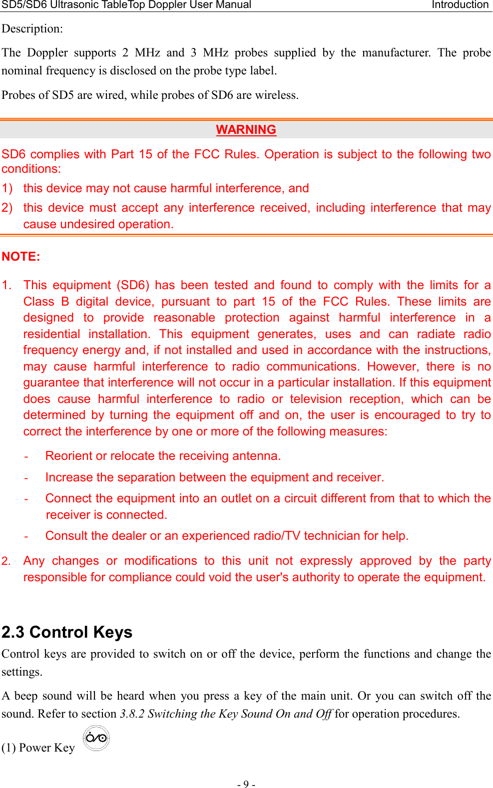
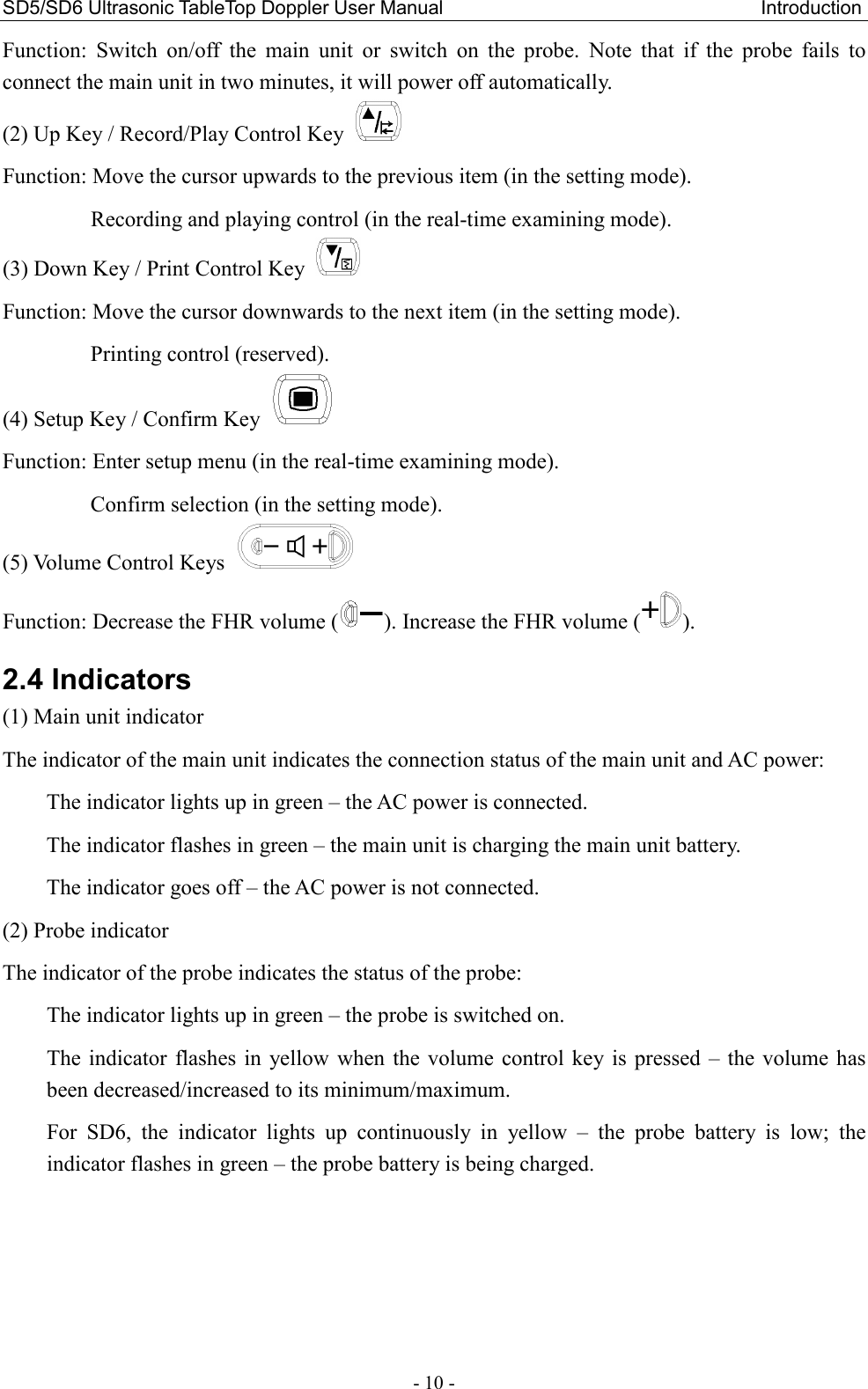
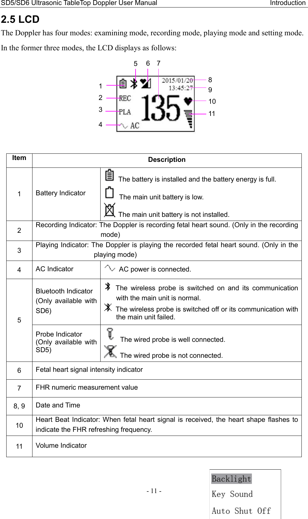
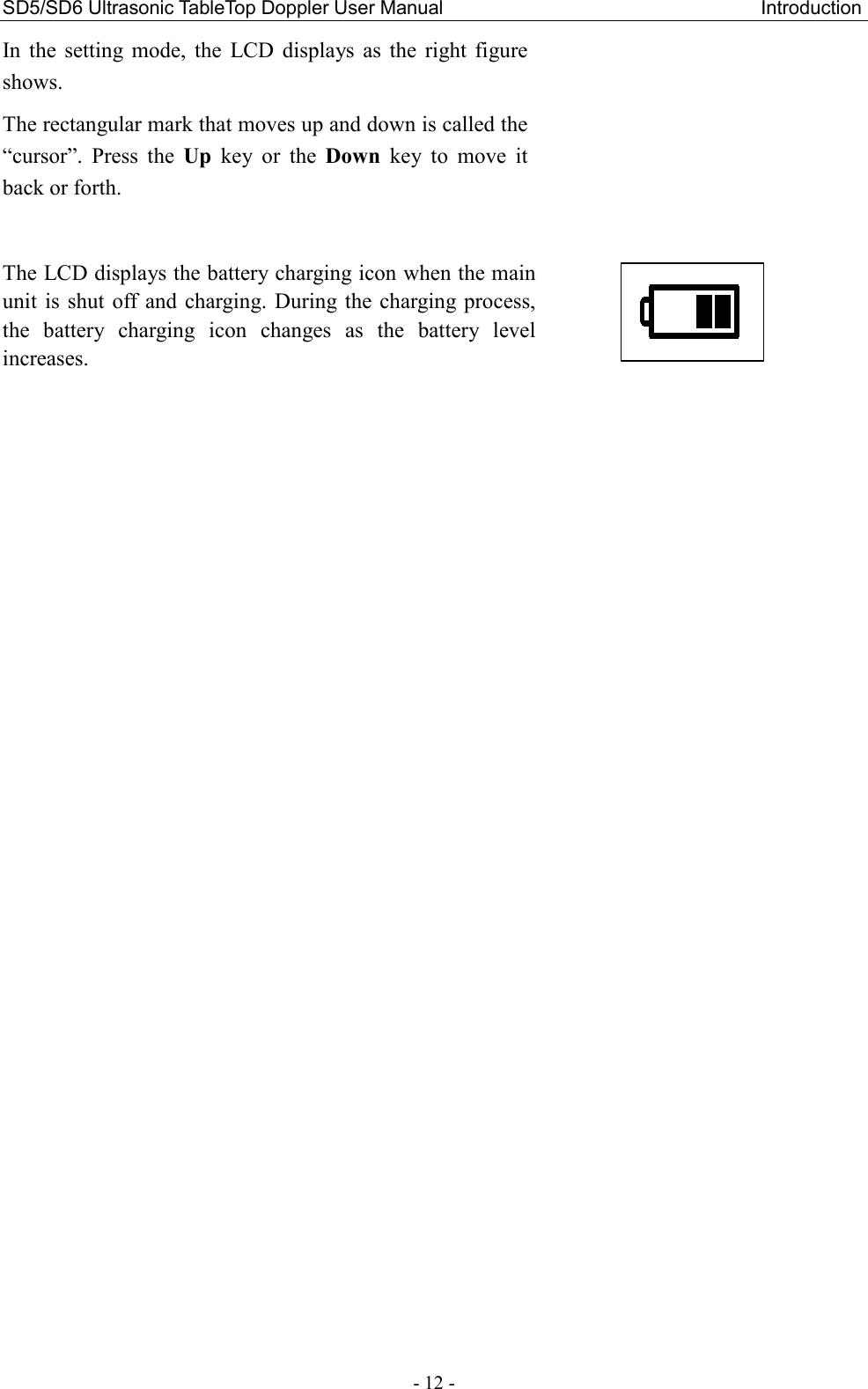
EDAN INSTRUMENTS SD6PEDAN Ultrasonic TableTop Doppler Probe User Manual

EDAN INSTRUMENTS, INC. Ultrasonic TableTop Doppler Probe

User manual

 I About this Manual P/N: 01.54.456994 MPN: 01.54.456994011 Release Date: Oct. 2015 © Copyright EDAN INSTRUMENTS, INC. 2015. All rights reserved. Statement This manual will help you understand the operation and maintenance of the product better. It is reminded  that  the  product  shall  be  used  strictly  complying  with  this  manual.  User’s  operation failing  to  comply  with  this  manual  may  result  in  malfunction  or  accident  for  which  EDAN INSTRUMENTS, INC. (hereinafter called EDAN) can not be held liable. EDAN  owns  the  copyrights  of  this  manual.  Without  prior  written  consent  of  EDAN,  any materials contained in this manual shall not be photocopied, reproduced or translated into other languages. Materials  protected  by  the  copyright  law,  including but  not  limited  to  confidential  information such as technical information and patent information are contained in this manual, the user shall not disclose such information to any irrelevant third party. The  user  shall  understand  that  nothing  in  this  manual  grants  him,  expressly  or  implicitly,  any right or license to use any of the intellectual properties of EDAN. EDAN holds the rights to modify, update, and ultimately explain this manual. Responsibility of the Manufacturer EDAN only considers itself responsible for  any effect  on  safety,  reliability and  performance of the equipment if: Assembly  operations,  extensions,  re-adjustments,  modifications  or  repairs  are  carried  out  by persons authorized by EDAN, and The electrical installation of the relevant room complies with national standards, and The instrument is used in accordance with the instructions for use. Upon  request,  EDAN  may  provide,  with  compensation,  necessary  circuit  diagrams,  and  other information  to  help  qualified  technician  to  maintain  and  repair  some  parts,  which  EDAN  may define as user serviceable. Terms Used in this Manual This guide is designed to give key concepts on safety precautions. WARNING A  WARNING  label  advises  against  certain  actions  or  situations  that  could  result  in  personal
 II injury or death. CAUTION A CAUTION label advises against actions or situations that could damage equipment, produce inaccurate data, or invalidate a procedure. NOTE A NOTE provides useful information regarding a function or a procedure.
 III Table of Contents Chapter 1 Safety Guide ................................................................................................................. 1 1.1 Intended Use/Indications for Use ........................................................................................ 1 1.2 Safety Precautions ............................................................................................................... 1 1.3 Symbols ............................................................................................................................... 4 Chapter 2 Introduction .................................................................................................................. 6 2.1 Main Unit ............................................................................................................................ 6 2.2 Probes .................................................................................................................................. 8 2.3 Control Keys ....................................................................................................................... 9 2.4 Indicators ........................................................................................................................... 10 2.5 LCD ................................................................................................................................... 11 Chapter 3 Basic Operation .......................................................................................................... 13 3.1 Opening Package and Checking........................................................................................ 13 3.2 Using Batteries .................................................................................................................. 13 3.2.1 Fitting Main Unit Battery ........................................................................................ 13 3.2.2 Fitting Wireless Probe Battery ................................................................................ 15 3.2.3 Charging Main Unit Battery.................................................................................... 16 3.2.4 Charging Wireless Probe Battery ............................................................................ 16 3.2.5 Care of Batteries ...................................................................................................... 17 3.3 Connecting the Power Cable ............................................................................................. 17 3.4 Using Wired Probe ............................................................................................................ 17 3.4.1 Probe Socket ........................................................................................................... 17 3.4.2 Connecting and Disconnecting a Wired Probe ....................................................... 18 3.5 Switching On ..................................................................................................................... 18 3.6 Switching Off .................................................................................................................... 19 3.7 Using Earphone ................................................................................................................. 20 3.8 Changing Doppler Settings ............................................................................................... 20 3.8.1 Switching Backlight On and Off ............................................................................. 20 3.8.2 Switching Key Sound On and Off .......................................................................... 20 3.8.3 Setting Auto-Shut-Off Time ................................................................................... 21 3.8.4 Choosing Language ................................................................................................. 21 3.8.5 Setting Date and Time ............................................................................................. 21 3.8.6 Setting Date Format ................................................................................................ 21 3.9 Replacing Fuses ................................................................................................................ 22 Chapter 4 FHR Examining ......................................................................................................... 23 Chapter 5 Recording and Playing .............................................................................................. 25 Chapter 6 Maintenance and Cleaning ....................................................................................... 26
 IV 6.1 Inspection .......................................................................................................................... 26 6.2 Maintenance ...................................................................................................................... 26 6.3 Cleaning ............................................................................................................................ 27 6.4 Disinfection ....................................................................................................................... 27 6.5 Sterilization ....................................................................................................................... 28 Chapter 7 Warranty and Service ............................................................................................... 29 7.1 Warranty ............................................................................................................................ 29 7.2 Contact information .......................................................................................................... 29 Chapter 8 Product Specifications ............................................................................................... 30 8.1 Environmental Specifications ........................................................................................... 30 8.2 Physical Specifications ..................................................................................................... 30 8.3 Performance Specifications ............................................................................................... 31 8.4 Battery Specifications ....................................................................................................... 32 8.5 Low Output Summary Table ............................................................................................. 33 Appendix 1 Ordering Information ............................................................................................. 34 Appendix 2 EMC Information .................................................................................................... 35 A2.1 Electromagnetic Emissions ............................................................................................ 35 A2.2 Electromagnetic Immunity ............................................................................................. 36 A2.3 Electromagnetic Immunity ............................................................................................. 37 A2.4 Recommended Separation Distances ............................................................................. 38 Appendix 3 Ultrasound Intensity and Safety ............................................................................ 39 A3.1 Ultrasound in Medicine .................................................................................................. 39 A3.2 Ultrasound Safety and the ALARA Principle ................................................................ 39 A3.3 Explanation of MI/TI ..................................................................................................... 39 A3.3.1 MI (Mechanical Index) ........................................................................................ 39 A3.3.2 TI (Thermal Index) ............................................................................................... 40 A3.3.3 Measurement Uncertainties .................................................................................. 40 A3.4 Prudent Use Statement ................................................................................................... 40 A3.5 References for Acoustic Output and Safety ................................................................... 41 A3.6 Probe Acoustic Output Parameters List ......................................................................... 41 Appendix 4 Overall Sensitivity ................................................................................................... 43 A4.1 Overall Sensitivity of SD5 (2MHz Wired Probe) .......................................................... 43 A4.2 Overall Sensitivity of SD5 (3MHz Wired Probe) .......................................................... 44 A4.3 Overall Sensitivity of SD6 (2MHz Wireless Probe) ...................................................... 45 A4.4 Overall Sensitivity of SD6 (3MHz Wireless Probe) ...................................................... 46
SD5/SD6 Ultrasonic TableTop Doppler User Manual                                                                Safety Guide - 1 - Chapter 1 Safety Guide NOTE: Familiarize  yourself  with  this  user  manual  before  attempting  to  operate  the  Doppler. Follow the operation and maintenance instructions to ensure proper use of it. 1.1 Intended Use/Indications for Use The SD5 Ultrasonic TableTop Doppler (hereinafter called “SD5”) and SD6 Ultrasonic TableTop Doppler (hereinafter called “SD6”) are intended to be used by health care professionals including registered nurses, practical nurses, midwives, ultrasound technicians, and physician assistants, by prescription from licensed physicians in hospitals, clinics and private offices. The  2  MHz  and/or  3  MHz  obstetrical  probes  are  indicated  for  the  detection  of  fetal  heart  rate from early gestation thru delivery and as a general indication of fetal well being. They can also be used to verify fetal heart viability. 1.2 Safety Precautions WARNING  and  CAUTION  messages  must  be  observed.  To  avoid  the  possibility  of  injury, observe the following precautions during the operation of the device. WARNING 1  SD5/SD6 Ultrasonic TableTop Doppler is a tool to aid healthcare professionals and should  not  be  used  in  place  of  normal  fetal  monitoring.  It  is  not  intended  for treatment. 2  This device is not explosion-proof and can not be used in the presence of flammable anaesthetics. 3  SHOCK HAZARD – In order to protect the patient and the operator, the device case should be grounded. The power receptacle must be a three-slot grounded outlet. 4  SHOCK HAZARD – Do not attempt to connect or disconnect a power cord with wet hands. Make sure that your hands are clean and dry before touching a power cord. 5  Accessory  equipment  connected  to  the  analog  and  digital  interfaces  must  be certified according to the respective IEC/EN standards (e.g. IEC/EN 60950 for data processing equipment and IEC/EN 60601-1 for medical equipment). Furthermore all configurations  shall  comply  with  the  valid  version  of  the  system  standard  IEC/EN 60601-1. Anybody who connects additional equipment to the signal input connector or  signal  output  connector  to  configure  a  medical  system  must  ensure  that  the system complies with the requirements of the valid version of the system standard IEC/EN 60601-1. If in doubt, consult our technical service department or your local distributor. 6  Exposure to ultrasound should be kept as low as reasonably achievable.
SD5/SD6 Ultrasonic TableTop Doppler User Manual                                                                Safety Guide - 2 - WARNING 7  Do not touch the signal input/output connector and the patient simultaneously. 8  Do not apply this device and other ultrasonic equipment simultaneously on the same patient, in case of possible hazard caused by leakage current superposition. 9  Do not apply this device simultaneously with other PATIENT-connected equipment, such as, a cardiac pacemaker or other electrical stimulators, on the same patient. 10  The device is not protected against defibrillation. 11  Do not use the device with HF surgical equipment. 12  Only use the probes provided by the manufacturer. 13  Before using the battery, make sure to read the user manual and safety precautions thoroughly. 14  Do not heat or throw the battery into fire as this may cause explosion. 15  Do not solder the leading wire and the battery terminal directly. 16  Do not destroy the battery: Do not pierce the battery with a sharp object such as a needle; do not hit with a hammer, step on or throw or drop to cause strong shock; do not disassemble or modify the battery. 17  The battery should be charged, used or stored away from the static electricity. 18  Do not mix the battery with metal objects to avoid short-circuit. 19  The battery should be charged at least once a month to prevent overdischarge. 20  Replacement or charging of the battery shall be done at least 1.5 meters away from patients. 21  The device shall only be used when the battery cover is closed. 22  If the device is not used for a long time, please remove the battery and store it as required. 23  If the liquid leak from the battery spills onto your skin or clothes, wash well with fresh water immediately. 24  If  the liquid  leak  from the  battery gets into  eyes,  do  not  rub the  eyes. Wash them well with clean water and see a doctor immediately. 25  Stop using the battery if abnormal heat, odor, discoloration, deformation or any other abnormal  condition  is  detected  during  use,  charge,  or  storage.  Please  dispose  it according to the local regulations. 26  Do not immerse, throw, or wet the battery in water/seawater. 27  Do  not  connect  any  equipment  or  accessories  that  are  not  approved  by  the manufacturer or that are not IEC 60601-1 approved to the device. The operation or use  of  non-approved  equipment  or  accessories  with  the  device  is  not  tested  or supported, and device operation and safety are not guaranteed.
SD5/SD6 Ultrasonic TableTop Doppler User Manual                                                                Safety Guide - 3 - WARNING 28  Using  accessories  other  than  those  specified  by  the  manufacturer  may  result  in increased electromagnetic emissions or decreased electromagnetic immunity of the device. 29  The appliance coupler or mains plug is used as isolation means from supply mains. Position  the  device  in  a  location  where  the  operator  can  easily  access  the disconnection device. 30  The device should not be used adjacent to or stacked with other equipment and that if  adjacent  or  stacked  use  is  necessary,  the  device  should  be  observed  to  verify normal operation in the configuration in which it will be used. 31  The  medical  electrical  equipment  needs  to  be  installed  and  put  into  service according to the EMC Information provided in this user manual. 32  Portable  and  mobile  RF  communications  equipment  can  affect  medical  electrical equipment, refer to section A2.4 Recommended Separation Distances. 33  Do  not  service  or  maintain  the  device  or  any  accessory  which  is  in  use  with  a patient. CAUTION 1  Federal (U.S.) law restricts this device to sale by or on the order of a physician. 2  Refer servicing to qualified service personnel. 3  The  main  unit  is  designed  for  continuous  operation  and  is  ‘ordinary’.  It  is  not waterproof; do not immerse it in any liquid (i.e. not drip or splash-proof). 4  Keep the device clean. Avoid vibration. 5  Do not sterilize the Doppler with autoclave or gas. 6  Electromagnetic Interference – Ensure that the environment in which the device is operated is not subject to any source of strong electromagnetic emissions, such as radio transmitters, mobile telephones, etc. 7  Check that the equipment does not have visible evidence of damage that may affect personnel’s  safety  or  examining  capability  before  use.  If  damage  is  detected, replacement is recommended. 8  The  device  and  accessories  are  to  be  disposed  of  according  to local  regulations after  their  useful  lives.  Alternatively,  they  can  be  returned  to  the  dealer  or  the manufacturer  for  recycling  or  proper  disposal.  Batteries  are  hazardous  waste.  Do NOT dispose them together with house-hold garbage. At the end of  their life hand the  batteries  over  to  the  applicable  collection  points  for  the  recycling  of  waste batteries.  For  more  detailed  information  about  recycling  of  this  product  or  battery, please contact your local Civic Office, or the shop where you purchased the product.
SD5/SD6 Ultrasonic TableTop Doppler User Manual                                                                Safety Guide - 4 - 1.3 Symbols No.  Symbol  Definition 1  Headphones 2  Equipotential grounding 3  Alternating Current 4  Fuse 5   ON/OFF switch 6  Menu 7  Recording and play-back 8   Print control 9   Move the cursor downwards   10   Move the cursor upwards 11   Speaker 12   Decrease 13   Increase 14   Charge battery 15   Push right 16  Caution 17  Operating instructions
SD5/SD6 Ultrasonic TableTop Doppler User Manual                                                                Safety Guide - 5 - 18  TYPE BF APPLIED PART 19   CE marking 20  Disposal method 21  IPX4 The device is protected against splashing water. Water splashed against the enclosure from any direction shall have no harmful effects. 22   Part Number 23   SERIAL NUMBER 24  Date of manufacture 25  MANUFACTURER 26   AUTHORISED  REPRESENTATIVE  IN  THE  EUROPEAN COMMUNITY 27  General symbol for recovery/recyclable 28   Caution:  Federal  (U.S.)  law  restricts this  device  to  sale  by or on the order of a physician. 29  Refer to User Manual (Background: Blue; Symbol: White) 30  Non-ionizing electromagnetic radiation 31*  FCC ID: SMQSD6PEDAN Federal  Communications  Commission:  FCC  ID: SMQSD6PEDAN 32*  FCC ID: SMQSD6MEDAN Federal  Communications  Commission:  FCC  ID: SMQSD6MEDAN NOTE: 1  The user manual is printed in black and white. 2  * Applicable to SD6 only.
SD5/SD6 Ultrasonic TableTop Doppler User Manual                                                                  Introduction - 6 - Chapter 2 Introduction NOTE: The pictures and interfaces in this manual are for reference only. 2.1 Main Unit SD5:  SD6:    Figure 2-1 Overview    Figure 2-2 Top View of the Main Unit 1 Probe 2 Probe Cable 3 Main Unit 4 LCD 5 Speakers 6 Probe Socket 8  9 10 7 Probe Holder 8 Handle 9 Probe Sensor Socket 10 Main Unit Control Keys 1  2  3  4  5   6  5      3 4   5  5  7 1
SD5/SD6 Ultrasonic TableTop Doppler User Manual                                                                  Introduction - 7 - WARNING Please do not touch the probe sensor socket and the patient simultaneously.     Figure 2-3 Main Unit Control Keys    Figure 2-4 Back View of the Main Unit  Figure 2-5 Right View of the Main Unit  NOTE:   The main unit is not waterproof. Do not immerse it in any type of liquid.   18  17 16  20 19 16 Fuses 17 Power Socket 18 Equipotential Grounding Terminal 19 Main Unit Label 20 Earphone Socket 21 Battery Compartment 21 11        12              13            14              15 11 Main Unit Indicator 12 On/OFF Key 13 Setup Key / Confirm Key 14 Up Key / Record/Play Control Key 15 Down Key /   Print Control Key
SD5/SD6 Ultrasonic TableTop Doppler User Manual                                                                  Introduction - 8 - 2.2 Probes WARNING Do not touch the charge sockets of the Doppler probe and the patient simultaneously. CAUTION 1.  Do not immerse the probe (and the probe cable) in any liquid. 2.  Do not stretch the probe cable for more than three meters. Wireless Probe:    Wired Probe:     Figure 2-6 Top View of the Probe   Figure 2-7 Probe Control Keys   Figure 2-8 Bottom View of the Probe 1 Acoustic Face 2 Probe Control Keys 3 Probe Socket 4 Probe Cable    2 1   5        6              7     8 9 Probe Type Label 10 Probe Battery Compartment 11 Probe Charge Socket           9          10              11 43 1  2  5 Volume Decreasing Key 6 Volume Increasing Key 7  Power  Key  (only  available on wireless probe) 8 Probe Indicator
SD5/SD6 Ultrasonic TableTop Doppler User Manual                                                                  Introduction - 9 - Description: The  Doppler  supports  2  MHz  and  3  MHz  probes  supplied  by  the  manufacturer.  The  probe nominal frequency is disclosed on the probe type label. Probes of SD5 are wired, while probes of SD6 are wireless. WARNING SD6 complies with Part 15 of the FCC Rules. Operation is subject to the following two conditions:   1)  this device may not cause harmful interference, and   2)  this  device  must  accept  any  interference  received,  including  interference  that  may cause undesired operation. NOTE: 1.  This  equipment  (SD6)  has  been  tested  and  found  to  comply  with  the  limits  for  a Class  B  digital  device,  pursuant  to  part  15  of  the  FCC  Rules.  These  limits  are designed  to  provide  reasonable  protection  against  harmful  interference  in  a residential  installation.  This  equipment  generates,  uses  and  can  radiate  radio frequency energy and, if not installed and used in accordance with the instructions, may  cause  harmful  interference  to  radio  communications.  However,  there  is  no guarantee that interference will not occur in a particular installation. If this equipment does  cause  harmful  interference  to  radio  or  television  reception,  which  can  be determined  by  turning  the  equipment  off  and  on,  the  user  is  encouraged  to  try  to correct the interference by one or more of the following measures: -  Reorient or relocate the receiving antenna. -  Increase the separation between the equipment and receiver. -  Connect the equipment into an outlet on a circuit different from that to which the receiver is connected. -  Consult the dealer or an experienced radio/TV technician for help. 2. Any  changes  or  modifications  to  this  unit  not  expressly  approved  by  the  party responsible for compliance could void the user's authority to operate the equipment.  2.3 Control Keys Control keys are provided to switch on or off the device, perform the functions and change the settings. A  beep  sound  will be heard when  you press  a  key of  the  main unit.  Or  you can  switch  off the sound. Refer to section 3.8.2 Switching the Key Sound On and Off for operation procedures. (1) Power Key
SD5/SD6 Ultrasonic TableTop Doppler User Manual                                                                  Introduction - 10 - Function:  Switch  on/off  the  main  unit  or  switch  on  the  probe.  Note  that  if  the  probe  fails  to connect the main unit in two minutes, it will power off automatically. (2) Up Key / Record/Play Control Key   Function: Move the cursor upwards to the previous item (in the setting mode).                 Recording and playing control (in the real-time examining mode). (3) Down Key / Print Control Key   Function: Move the cursor downwards to the next item (in the setting mode).                 Printing control (reserved). (4) Setup Key / Confirm Key   Function: Enter setup menu (in the real-time examining mode).                 Confirm selection (in the setting mode). (5) Volume Control Keys   Function: Decrease the FHR volume ( ). Increase the FHR volume ( ). 2.4 Indicators (1) Main unit indicator The indicator of the main unit indicates the connection status of the main unit and AC power: The indicator lights up in green – the AC power is connected. The indicator flashes in green – the main unit is charging the main unit battery. The indicator goes off – the AC power is not connected. (2) Probe indicator The indicator of the probe indicates the status of the probe: The indicator lights up in green – the probe is switched on. The indicator  flashes  in yellow  when  the volume  control  key is  pressed  –  the  volume has been decreased/increased to its minimum/maximum. For  SD6,  the  indicator  lights  up  continuously  in  yellow  –  the  probe  battery  is  low;  the indicator flashes in green – the probe battery is being charged.
SD5/SD6 Ultrasonic TableTop Doppler User Manual                                                                  Introduction - 11 - 2.5 LCD The Doppler has four modes: examining mode, recording mode, playing mode and setting mode.   In the former three modes, the LCD displays as follows:     Item Description 1  Battery Indicator   The battery is installed and the battery energy is full.     The main unit battery is low.   The main unit battery is not installed. 2  Recording Indicator: The Doppler is recording fetal heart sound. (Only in the recording mode) 3  Playing Indicator: The Doppler is playing the recorded fetal heart sound. (Only in the playing mode) 4  AC Indicator    AC power is connected. 5 Bluetooth Indicator (Only  available  with SD6)  The  wireless  probe  is  switched  on  and  its  communication with the main unit is normal.  The wireless probe is switched off or its communication with the main unit failed. Probe Indicator (Only  available  with SD5)   The wired probe is well connected.   The wired probe is not connected. 6  Fetal heart signal intensity indicator 7  FHR numeric measurement value 8, 9  Date and Time 10  Heart Beat  Indicator: When fetal heart  signal is  received, the  heart  shape flashes  to indicate the FHR refreshing frequency. 11  Volume Indicator  1 2 3 8 9 10 11 5 4 6    7
SD5/SD6 Ultrasonic TableTop Doppler User Manual                                                                  Introduction - 12 - In  the setting  mode,  the  LCD  displays  as the  right  figure shows.   The rectangular mark that moves up and down is called the “cursor”.  Press  the  Up  key  or  the  Down  key  to  move  it back or forth.  The LCD displays the battery charging icon when the main unit  is  shut off  and  charging. During the  charging  process, the  battery  charging  icon  changes  as  the  battery  level increases.
SD5/SD6 Ultrasonic TableTop Doppler User Manual                                                          Basic Operation - 13 - Chapter 3 Basic Operation 3.1 Opening Package and Checking Open the package; take out the Doppler and accessories carefully. Place them on a flat, clean surface. Keep the package for possible future transportation or storage. Check the components according to the packing list.  Check for any mechanical damage.  Check all the cables and accessories. If there is any problem, contact us or your local distributor immediately. 3.2 Using Batteries  CAUTION The  fitting  of  the  batteries  should  be  carried  out  by  the  manufacturer's  authorized personnel.  3.2.1 Fitting Main Unit Battery The main unit is powered either by alternating current or a Ni-MH battery. It is recommended to power the main unit solo by a battery during operation. Therefore, charge the battery fully before use to ensure enough power. Connecting to mains power supply will charge the battery no matter if the main unit is on or off. WARNING Switch off the Doppler and remove the power cord before fitting the main unit battery. To fit the battery for the main unit: 1 Follow the arrow direction to open the battery compartment cover. The battery connecting cable & connector and the metal insert show up.
SD5/SD6 Ultrasonic TableTop Doppler User Manual                                                          Basic Operation - 14 -      2 Tilt the battery sideways and put its bottom left corner into the battery compartment from the left end of the compartment to the right. Make sure connector ① stays out of the compartment.  3 Keep pushing the battery into the compartment until the metal insert springs back to lock the battery.   Battery Connecting Cable & Connector Metal Insert Battery  Connector  ①      Battery  Connector  ②
SD5/SD6 Ultrasonic TableTop Doppler User Manual                                                          Basic Operation - 15 - 4 Connect the two connectors (①&②) and then put them into the compartment.  5 Close the battery compartment cover.  3.2.2 Fitting Wireless Probe Battery  The wireless probe is powered by a lithium battery.   To fit the battery for the probe: 1 Remove the screw on the battery compartment cover with a screw driver and then take the cover away with your hand.
SD5/SD6 Ultrasonic TableTop Doppler User Manual                                                          Basic Operation - 16 - 2 Fit the battery. Make sure the polarities correspond with the battery compartment diagram.    3 Close the battery compartment cover and fix it with the screw.      3.2.3 Charging Main Unit Battery Observe the battery indicator on the LCD, the panes in it indicate the main unit battery electric energy.  They  go off  gradually with  the consumption  of  the battery.  When  the  battery  indicator turns into “ ”, the battery power is low. You need to switch to outer AC power and charge the battery in time. To charge the main unit battery, you need to connect the Doppler to 100 V-240 V~ power supply.   Connecting the main unit to the AC power supply will charge the battery, no matter if it is on or off. If the main unit is in the stand-by or switch off state, it takes no more than 5 hours to fully charge the main unit battery. During this period, the main unit indicator flashes in green, and the panes in the battery indicator increase gradually. When the battery is fully charged, the indicator has four panes. 3.2.4 Charging Wireless Probe Battery When the wireless probe battery is low, the probe power indicator turns into yellow. You need to switch off the probe and charge the battery in time. To charge the probe battery, you need to place the probe in the probe holder. Then connect the main unit to the AC power supply.   If the probe is in the switch off state, it takes no more than 5 hours to fully charge the probe battery. During this period, both the main unit indicator and the probe indicator will flash in green.
SD5/SD6 Ultrasonic TableTop Doppler User Manual                                                          Basic Operation - 17 - 3.2.5 Care of Batteries WARNING 1  Replacement or charging of batteries shall be done at least 1.5 meters away from the patient. 2  Close the battery compartment before using the main unit or the probe. 3  Do not expose the batteries to high temperature, heat them or dispose of them in fire. 4  Do not disassemble the batteries. 5  Short circuit should be avoided. CAUTION 1  If the Doppler is not used for an extended period, remove the batteries and keep the batteries in a cool and dry environment. The environment temperature must not exceed the range of -20°C ~ +40°C (-4°F ~ +104°F). 2  If the Doppler is not used for an extended period, charge the batteries at least once a month. 3  The  batteries  must  be  properly  disposed  according  to  local  regulations  after  their useful life. 3.3 Connecting the Power Cable Apply the power cable provided with the Doppler. Put the connector of the power cord to the power socket on the Doppler (figure 2-4). Put the plug of the power cord into a grounded 3-slot power output special for hospital usage. NOTE:   Make sure the AC power supply of the Doppler complies with the following specification: 100 V-240 V~, 50 Hz/60 Hz. WARNING If  the  protective  grounding  (protective  earth)  system  is  doubtful,  the  Doppler  must  be supplied only by inner power. 3.4 Using Wired Probe 3.4.1 Probe Socket SD5 adopts wired probes. The probe cable is a telephone cable with a standard RJ11 plug on each terminal.
SD5/SD6 Ultrasonic TableTop Doppler User Manual                                                          Basic Operation - 18 - RJ11 Interface:  3.4.2 Connecting and Disconnecting a Wired Probe To connect the wired probe to the main unit: 1 Take out the probe cable from package. Insert one modular plug of the cable into the probe socket of the main unit.   2 Insert the other modular plug into the probe socket of the probe.         To disconnect the probe, press the housing of the modular plug and then pull it out.    3.5 Switching On WARNING Make sure all the metal parts are linked to the protective earth cord and the power cord is free of damage before switching on the main unit. Modular Plug Housing 1      Power 2      GND 3      Signal Wire 4      Signal Wire
SD5/SD6 Ultrasonic TableTop Doppler User Manual                                                          Basic Operation - 19 - CAUTION To avoid unwanted noise, do not take out or place the probe when the main unit is on. Remember to take out the probe before switching on the main unit, and place the probe after switching off the main unit. To switch on the main unit: Pick up the probe and then press the ON/OFF key    on the main unit. All the real-time examining menu elements light up in a few seconds. A start-up sound (if the key sound is enabled) is heard. The Doppler performs a self test by displaying the FHR numerics in a fast speed. To switch on the wireless probe: Press the Power key    on the wireless probe. The probe indicator lights up in green. NOTE:   1  For  SD6,  the  Power  keys  of  the  wireless  probe  and  the  main  unit  need  to  be pressed  separately.  After  they  are  switched  on,  they  will  be  connected  with  each other  automatically,  and  the  LCD  will  display    to  indicate  normal  connection.  If you touch the acoustic faceplate of the probe gently with your hand, the Doppler will give out sound. 2  For  SD6,  docking  the  probe  when  the  main  unit  is  powered  on  and  is  in  normal connection with the probe, the probe will turn off automatically and begin to charge. If you take up the probe within 3 hours, it will power on automatically and be ready for use.   3  For SD5, the wired probe is ready to use when the main unit is switched on. 3.6 Switching Off When the examination is finished, switch off the main unit, wipe the remaining gel off the probe with a clean soft cloth and then place the probe back into the holder. To switch off the main unit, perform any one of these operations: 1) Press the ON/OFF key    on the main unit. 2) Put the probe into the probe holder. 3) Auto shut off. If the main unit does not receive signal for a period of time, it will be switched off automatically. The auto-shut-off time is preset in the setup menu. Refer to section 3.8.3 Setting Auto-Shut-Off Time.
SD5/SD6 Ultrasonic TableTop Doppler User Manual                                                          Basic Operation - 20 - To switch off the wireless probe: NOTE: 1  If the probe is not to be used over a relatively long period of time, It is recommended to switch off the main unit first, and then put the probe into the probe holder. 2  For  SD6,  if  you  switch  off  the  main  unit  when  it  is  in  normal  connection  with  the probe, the probe will also be switched off. 3.7 Using Earphone In a noisy environment, you are advised to use an earphone to hear fetal heart sound. Insert the earphone plug into earphone socket on the back of the main unit (figure 2-4). The speakers will be muted when the earphone is connected. WARNING Turn down the volume before using earphone to your ears. CAUTION Accessory  equipment  connected  to  the  analog  and  digital  interfaces  must  be  certified according  to  the  respective  IEC/EN standards (e.g.  IEC/EN  60950  for data processing equipment and IEC/EN 60601-1 for medical equipment). Furthermore all configurations shall  comply  with  the  valid  version  of  the  system  standard  IEC/EN  60601-1.  Anybody who  connects  additional  equipment  to  the  signal  input  connector  or  signal  output connector to configure a medical system must ensure that the system complies with the requirements  of  the  valid  version  of  the  system  standard  IEC/EN  60601-1.  If  in  doubt, consult our technical service department or your local distributor. 3.8 Changing Doppler Settings 3.8.1 Switching Backlight On and Off 1 Press the Setup key for about 2 seconds to open setup menu. 2 Press the Setup key when the cursor stays at Backlight. 3 Press the Up/Down key to toggle between ON and OFF. 4 Press the Setup key.  3.8.2 Switching Key Sound On and Off 1 Press the Setup key for about 2 seconds to open setup menu. 2 Press the Up/Down key to move the cursor to Key Sound, press the Setup key. 3 Press the Up/Down key to toggle between ON and OFF.
SD5/SD6 Ultrasonic TableTop Doppler User Manual                                                          Basic Operation - 21 - 4 Press the Setup key.  3.8.3 Setting Auto-Shut-Off Time The Auto-Shut-Off feature facilitates the economical use of the Doppler. The main unit will switch off automatically after no signal is received and no operation is performed for 1 minute, 3 minutes or infinite time. 1 Press the Setup key for about 2 seconds to open setup menu. 2 Press the Up/Down key to move the cursor to Auto Shut Off, press the Setup key. 3 Press the Up/Down key to move the cursor among options. 4 Press the Setup key.  3.8.4 Choosing Language 1 Press the Setup key for about 2 seconds to open setup menu. 2 Press the Up/Down key to move the cursor to Language, press the Setup key. 3 Press the Up/Down key to select the required language. 4 Press the Setup key.  3.8.5 Setting Date and Time 1 Press the Setup key for about 2 seconds to open setup menu. 2 Press the Up/Down key to move the cursor to Real Time Clock, press the Setup key. 3 Press the Setup key when the cursor stays at Hour. 4 Press the Up/Down key to choose a number from 00 to 23 and then press the Setup key to confirm the choice. 5 In the same way, choose the Minute from 00 to 59. Choose the Year, Month and Day.   6 Move the cursor to EXIT and then press the Setup key. 3.8.6 Setting Date Format You can choose to switch the date on or off. When it is on, the date format has three options: DD/MM/YYYY, MM/DD/YYYY and YYYY/MM/DD. To switch the date on and off or change date format: 1 Press the Setup key for about 2 seconds to open setup menu. 2 Press the Up/Down key to move the cursor to Date Format, press the Setup key. 3 Press the Up/Down key to toggle between ON and OFF. If you choose ON, the cursor moves to the date format. Select a format. 4 Press the Setup key.  NOTE:   If no operation is performed in 30 seconds, the device will exit from the setup menu. The
SD5/SD6 Ultrasonic TableTop Doppler User Manual                                                          Basic Operation - 22 - setting changes will not be effective.  3.9 Replacing Fuses WARNING Switch off the main unit and unplug it before replacing the fuses. Two fuses are located on the rear panel of the device, their specifications are:   Size: Ф5 mm*20 mm; Model: T400mAH250V. When any one of the fuses is blown, perform the following steps to replace it: 1. Using a  flat-head  screw driver,  push  the  fuse  in for  about  one millimeter  and  then rotate  it anticlockwise. 2. Remove the old fuse and replace it with a new fuse that is supplied by the manufacturer or of the same specifications. 3. Push the new fuse into the socket for about one millimeter and then rotate it clockwise back into position.
SD5/SD6 Ultrasonic TableTop Doppler User Manual                                                          FHR Examining - 23 - Chapter 4 FHR Examining WARNING 1  Always check if the main unit and the probe are in good condition prior to use. 2  To avoid inaccurate diagnosis: (a) relocate the probe for the best FHR signal as the fetal  position  changes;  (b)  when  intrauterine  fetal  death  is  doubted  by  using  this examination method, try to verify it with other methods. CAUTION Handle the probe with care. Do not drop it on hard surfaces. The 2 MHz and 3 MHz obstetrical probes are designed for FHR examining. The 2 MHz probe is optimized for deep penetration and is widely used in the third trimester pregnancy. The 3 MHz probe  is  a general  purpose  probe.  It has  better  resolution  and  wider detection  range  than the  2 MHz probe, therefore is optimized for early fetal heart detection. Follow these procedures to perform FHR examining: 1 Feel the position of the fetus by hand to find the best position to detect the fetal heart.   2 Switch on the Doppler and the probe. 3 Apply a small amount of coupling gel to the acoustic face of probe; place the probe face at the best  position  for  detecting  fetal  heart.  Angle  the  probe  to  obtain  an  optimum  audio  signal. Adjust the volume if required. When  an  audible  fetal  heart signal is  detected,  a clear fetal heart  sound  will  be heard from the speakers/earphone, and numeric FHR value will be displayed on the LCD.  NOTE: 1  The best quality records will only be obtained if the probe is placed in the optimum position. 2  Positions  with  strong  placental  sounds  or  umbilical  blood  flow  sound should  be avoided. 3  If  the  fetus  is  in  the  cephalic  position  and  the  mother  is  supine,  the  clearest  heart sound will normally be found on the midline below the umbilicus. During examining, the  pregnant  woman’s  prolonged  lying  in  the  supine  position  should  be  avoided owing  to  the  possibility  of  supine  hypotension.  Sitting  up  or  lateral  positions  are preferable and may be more comfortable. 4  It  is  not  possible  to  obtain  accurate  FHR  unless  an  audible  fetal  heart  signal  is detected. If the calculated FHR is not in accordance with the beat of the fetal heart sound, the fetal heart sound auscultation result shall prevail.
SD5/SD6 Ultrasonic TableTop Doppler User Manual                                                          FHR Examining - 24 - 5  When applied to the patient, the ultrasound transducer may warm slightly (less than 8°C  (14.4°F)  above  ambient  temperature).  When  NOT  applied,  the  ultrasound transducer may reach the highest temperature of 8°C (14.4ºF). 6  Maternal heart will be detected if the probe is strongly placed on maternal vessel. 7  For SD6, the effective transmission distance between the main unit and the wireless probe is 5 meters. It is recommended that they are positioned within this distance in photopic vision.
SD5/SD6 Ultrasonic TableTop Doppler User Manual                                              Recording and Playing - 25 - Chapter 5 Recording and Playing The  built-in  recorder  of  the  Doppler  allows  recording  and  playing  fetal  heart  sound  of  240 seconds (at most). To record fetal heart sound: Press and hold  the  Record/Play control  key    for  two  seconds.  The  character REC  on  the LCD lights up. Recording starts.   Press  the  Record/Play  control  key    again  to  stop  recording  and  return  to  the  real-time examining mode.   To play the fetal heart sound: Press the Record/Play control key    in the real-time examining mode. The character PLA on the LCD lights up. The Doppler plays the recorded fetal heart sound. NOTE: Observe  the  LCD,  pay  attention  not  to  mistake  the  recorded  fetal  heart  sound  for  the real-time sound.
SD5/SD6 Ultrasonic TableTop Doppler User Manual                                        Maintenance and Cleaning - 26 - Chapter 6 Maintenance and Cleaning 6.1 Inspection (1) Visual Inspection Prior to using the device every time, do the following inspections:  Check the device and accessories to see if there is any visible evidence of damage that may affect patient safety.  Check the power socket and power cables.  Check if the device functions properly to make sure it is in good condition. If  any damage  is  detected, stop  using the  device on  the  patient. Replace  the damage part(s)  or contact the manufacturer for service before reusing it. (2) Routine Inspection The overall check of the device, including safety check and function check, should be performed by qualified personnel every 6 to 12 months, and each time after service. The equipment should undergo periodic safety testing to ensure proper patient isolation from live parts. This should include leakage current measurement and insulation testing. The recommended testing interval is once a year or as specified in the institution’s test and inspection protocol. (3) Mechanical Inspection Make sure all exposed screws are tight. Check the external cables for splits, cracks or signs of twisting. Replace any cable that shows serious damage. Pay particular attention to the supply socket. WARNING Failure on the part of the responsible individual hospital or institution employing the use of this equipment to implement a satisfactory maintenance schedule may cause undue equipment failure and possible health hazards.   CAUTION The maintenance must be performed by professional personnel. 6.2 Maintenance Avoid  scratching  and  damaging  the  LCD.  The  gathering  of  dew  on  the  LCD  may  occur  with abrupt temperature or humidity changes. A table environment is recommended for the main unit. Keep the exterior surface of the main unit clean, free of dust and dirt.
SD5/SD6 Ultrasonic TableTop Doppler User Manual                                        Maintenance and Cleaning - 27 - Handle the probe with care to avoid  damaging the  cover, piezoelectric crystals  and  mechanical movement. Do not contact the probe with hard or sharp objects.   Do not excessively flex the probe cable. Wipe the remaining gel off the probe after use. Keep the probes in a dry environment, where the temperature should be lower than 45°C.  6.3 Cleaning To clean the main unit: Switch off the Doppler  and unplug it  from AC  power supply. Clean the  case using a  soft  cloth dampened with mild near neutral detergent, ethanol (75%) or isopropanol (70%), and then wipe it dry with a dry cloth immediately. The recommended cycle is one week or when needed. Clean the probe after each use to avoid cross infection and prolong its useful life.   To clean the probe: Switch  off  the  probe.  Clean  it  using  a  soft  cloth  dampened  with  mild  near  neutral  detergent, ethanol (75%) or isopropanol (70%), and then wipe it dry with a dry cloth immediately. CAUTION 1  Do not use strong solvent such as acetone. 2  Do not use an abrasive such as steel wool or metal polish. 3  Neither the main unit nor the probe is waterproof; do not immerse any part of them in liquid. Entry of liquid into the Doppler may destroy the equipment. 4  Do not allow any liquid remain on the surface.  6.4 Disinfection In normal use the main unit does not  need disinfection. In case of being soiled, clean the main unit  case  and  then  disinfect  it  by  wiping  it  with  a  soft  cloth  dampened  with  ethanol  (75%)  or isopropanol (70%). Then wipe it dry with a dry cloth. After each use, clean the probe and then disinfect it by wiping it with a soft cloth dampened with ethanol (75%) or isopropanol (70%). Then wipe it dry with a dry cloth.
SD5/SD6 Ultrasonic TableTop Doppler User Manual                                        Maintenance and Cleaning - 28 - 6.5 Sterilization Do not sterilize the Doppler, unless this is necessary according to your hospital regulation. NOTE: After  cleaning  or  disinfection,  check  if  the  Doppler  function  well.  If  any  problem  is detected, please contact the manufacturer for service before reusing them. Checking Item Checking Method Visual Check  Inspect the Doppler for any damage. Function Check  Check if the Doppler can be switched on or off properly (see 3.5 Switching On and 3.6 Switching Off). When the Doppler is switched on, check if the LCD works as described in 2.5 LCD; touch the probe faceplate gently with your hand and check if the Doppler gives out sound normally.
SD5/SD6 Ultrasonic TableTop Doppler User Manual                                                Warranty and Service - 29 - Chapter 7 Warranty and Service 7.1 Warranty EDAN warrants that EDAN’s products meet the labeled specifications of the products and will be free from defects in materials and workmanship that occur within warranty period. The warranty is void in cases of: a) damage caused by mishandling during shipping. b) subsequent damage caused by improper use or maintenance. c) damage caused by alteration or repair by anyone not authorized by EDAN. d) damage caused by accidents. e) replacement or removal of serial number label and manufacture label. If a product covered by this warranty is determined to be defective because of defective materials, components, or workmanship, and the warranty claim is made within the warranty period, EDAN will, at its discretion, repair or replace the defective part(s) free of charge. EDAN will not provide a substitute product for use when the defective product is being repaired. 7.2 Contact information If you have any question about maintenance, technical specifications or malfunctions of devices, contact your local distributor. Alternatively, you can send an email to EDAN service department at: support@edan.com.cn.
SD5/SD6 Ultrasonic TableTop Doppler User Manual                                                Product Specifications - 30 - Chapter 8 Product Specifications 8.1 Environmental Specifications  Working Temperature:  0ºC ~ + 40ºC ( +32ºF ~ +104ºF) Relative Humidity: 15% RH ~ 95% RH (non-condensing) Atmospheric Pressure:  86 kPa ~ 106 kPa Transport and Storage Temperature:  -20ºC ~ +55ºC (-4ºF ~ +131ºF) Relative Humidity:  15% RH ~ 95% RH (non-condensing) Atmospheric Pressure:  70 kPa ~ 106 kPa  8.2 Physical Specifications  Dimensions and Weight Dimensions:  Main Unit: 265 mm x 155 mm x 180 mm Probes: 140 mm x 40 mm x 32 mm Weight: Main Unit: 1.7 kg (with battery and probe) Wireless Probe: <140 g (with battery) Wired Probe: <100 g Power Supply Main unit Operating Voltage: 100 V-240 V~ Operating Frequency: 50 Hz/60 Hz Input Power:  35 VA Battery: 7.2 V/2000 mAh (Ni-MH Battery) Probe Battery: 3.7 V/800 mAh (Lithium Battery) Standards Compliance IEC 60601-1:2005, EN 60601-1:2006, IEC 60601-1-2:2007,   EN 60601-1-2:2007, IEC/EN 60601-2-37 Anti-electric Shock Type  Class I equipment with internal power supply Anti-electric Shock Degree  Type BF applied parts
SD5/SD6 Ultrasonic TableTop Doppler User Manual                                                Product Specifications - 31 - Degree  of  Protection  against Harmful Ingress of Water Main  Unit:  Ordinary  equipment  (Sealed  equipment without liquid proof) Probe: IPX4 Degree  of  Safety  in  Presence  of Flammable Gases Equipment  not  suitable  for  use  in  presence  of flammable gases Disinfection/Sterilizing Method  Refer to this user manual for details EMC  CISPR 11 Group1 Class A Earth Leakage Current (Limit):  N.C.          S.F.C. 500 µA      1000 µA Enclosure Leakage Current (Limit): N.C.          S.F.C. 100 µA      500 µA Patient Leakage Current (Limit): N.C.        S.F.C. d.c.    10 µA      50 µA a.c.    10 µA      50 µA Patient Auxiliary Current (Limit): N.C.        S.F.C. d.c.    10 µA      50 µA a.c.    10 µA      50 µA Display: Effective display area:    62.0 mm (W) x 44.0 mm (H) Number of characters:    128*64 Dots Dot size:                          0.39 mm (W) x 0.55 mm (H) Dot pitch:                        0.44 mm (W) x 0.60 mm (H) Ultrasonic Gel: pH: 5.5~8.0 Acoustic Impedance: 1.5x10⁶ Pa.s/m ~1.7x10⁶ Pa.s/m (in 35°C(95ºF))  8.3 Performance Specifications  FHR Performance (Essential Performance): FHR Measurement Range:        50 bpm ~ 240 bpm Accuracy:                                  ± 2 bpm FHR Resolution:  1 bpm Recording and Playing: Audio Sampling Frequency:      4 kHz Recording Length:                      240 seconds White Back Light:  Two Brightness Adjustable:        OFF, ON
SD5/SD6 Ultrasonic TableTop Doppler User Manual                                                Product Specifications - 32 - Audio Output Power:  3 W Auto Shut off:  1-minute/3-minute no signal and no operation Bluetooth Transmission Distance:  Photopic vision: >5 m (the indoor distance depends on the building structure and material) Ultrasound: Nominal Frequency: 2 MHz Wired /Wireless Probes: 2 MHz 3 MHz Wired /Wireless Probes: 3 MHz Working Frequency: 2 MHz Wired /Wireless Probes: (2.0 ± 10%) MHz 3 MHz Wired /Wireless Probes: (3.0 ± 10%) MHz 2 MHz Wired/wireless probe:  Iob < 20 mW/cm2 3 MHz Wired/wireless probe: p- < 1 MPa Ispta < 100 mW/cm2 Isata < 20 mW/cm2 W0 < 50mW Working Mode: Continuous wave Doppler Effective Radiating Area of Probe: 2 MHz /3 MHz Wired /Wireless probes: (245±15%) mm2  8.4 Battery Specifications  For main unit  For probe Type:  Ni-MH Battery  Lithium Battery Nominal Capacity:  2000 mAh  800 mAh Nominal Voltage:  7.2 V  3.7 V Necessary Charge Time: ≤5  hours  (the  main  unit  is  in the  stand-by  or  switch  off state) ≤5  hours  (the  probe  is  in  the switch off state) Expected Battery Life: ≥8  hours  (the  new  battery  is fully  charged  before use,  and   the fetal heart sound at 1 meter right  ahead  of  the  main  unit speaker is higher than 80 dB) ≥3  hours  (the  new  battery  is fully charged before use)
SD5/SD6 Ultrasonic TableTop Doppler User Manual                                                Product Specifications - 33 - Circle Life:  ≥300 times   (after 300 circles, only 90% of the capacity can be restored.) Storage Temperature:  -20°C ∼ +60°C (-4 ºF ~ +140 ºF) (1 month) or -20°C ∼ +40°C (-4 ºF ~ +104 ºF) (3 months)  8.5 Low Output Summary Table Low Output Summary Table (for systems with no transducers having global maximum index values exceeding 1.0) System: Ultrasonic TableTop Doppler Transducer Model (MHz) Ispta.3 (mW/cm2)  TI Type  TI Value  MI  Isppa.3 (W/cm2) CW 2.0 (SD5)  1.774  TIS  0.0159  0.00628  0.001774 TIB  0.0301 CW 3.0 (SD5)  5.867  TIS  0.0969  0.00813  0.005867 TIB  0.1113 CW 2.0 (SD6)  3.484  TIS  0.0203  0.00785  0.003484 TIB  0.0531 CW 3.0 (SD6)  5.307  TIS  0.1132  0.00763  0.005307 TIB  0.1141
SD5/SD6 Ultrasonic TableTop Doppler User Manual                                                  Ordering Information - 34 - Appendix 1 Ordering Information CAUTION Only the parts supplied by the manufacturer should be used with the Doppler. Parts  Part Number Probe 2 MHz Wired Probe  02.01.212045 3 MHz Wired Probe  02.01.212046 Probe Cable  01.13.036108 2 MHz Wireless Probe  02.01.212047 3 MHz Wireless Probe  02.01.212048 Accessory   Ni-MH Battery for Main Unit  01.21.064220 Lithium Battery for Wireless Probe  01.21.064125 Carry Bag  01.56.465630 Power Cord (European Standard)  01.13.036638 Power Cord (American Standard)  21.13.036384
SD5/SD6 Ultrasonic TableTop Doppler User Manual                                                        EMC Information - 35 - Appendix 2 EMC Information A2.1 Electromagnetic Emissions  Guidance and manufacture’s declaration- electromagnetic emission The SD5/SD6 is intended for use in the electromagnetic environment specified below. The customer or the user of the SD5/SD6 should assure that it is used in such an environment. Emission test  Compliance  Electromagnetic environment-guidance RF emissions CISPR 11  Group 1 The  SD5/SD6  uses  RF  energy  only  for  its  internal function. Therefore, its RF emissions are very low and are not  likely  to  cause  any  interference  in  nearby  electronic equipment. RF emissions CISPR 11  Class A The  SD5/SD6  is  suitable  for  use  in  all  establishments, other  than  domestic  and  those  directly  connected  to  the public  low-voltage  power  supply  network  that  supplies building used for domestic purposes. Harmonic emissions IEC 61000-3-2  Class A Voltage fluctuations/flicker emissions IEC61000-3-3 Complies
SD5/SD6 Ultrasonic TableTop Doppler User Manual                                                        EMC Information - 36 - A2.2 Electromagnetic Immunity Guidance and manufacture’s declaration – electromagnetic immunity The SD5/SD6 is intended for use in the electromagnetic environment specified below. The customer or the user of SD5/SD6 should assure that it is used in such an environment.   Immunity test    IEC 60601 test level  Compliance level    Electromagnetic environment -guidance   Electrostatic discharge (ESD) IEC 61000-4-2 ±6 kV contact   ±8 kV air   ±6 kV contact ±8 kV air   Floors  should  be  wood, concrete  or  ceramic  tile.  If floor  are  covered  with synthetic material,  the relative humidity  should  be  at  least 30%.   Electrical  fast transient/burst IEC 61000-4-4 ±2  kV  for  power supply lines   ±2  kV  for  power supply lines   Mains power quality should be that of a typical commercial or hospital environment.   Surge IEC 61000-4-5 ±1 kV line(s) to line(s) ±2 kV line(s) to earth ±1 kV line(s) to line(s) ±2 kV line(s) to earth Mains power quality should be that of a typical commercial or hospital environment.   Power  frequency (50 Hz/60 Hz) magnetic field IEC61000-4-8 3 A/m    3 A/m   Power  frequency  magnetic fields  should  be  at  levels characteristic  of  a  typical location  in  a  typical commercial  or  hospital environment.   Voltage  dips,  short interruptions  and voltage  variations on  power  supply input lines IEC 61000-4-11 <5% UT   (>95% dip in UT)   for 0.5 cycle    40%  UT  (60%  dip  in UT) for 5 cycles    70%  UT  (30%  dip  in UT) for 25 cycles    <5%  UT  (>95%  dip  in UT) for 5s <5% UT   (>95%  dip  in  UT)  for 0.5 cycle    40%  UT  (60%  dip  in UT) for 5 cycles    70%  UT  (30%  dip  in UT) for 25 cycles    <5%  UT  (>95%  dip  in UT) for 5s Mains power quality should be that of a typical commercial or hospital  environment.  If  the user  of  the  SD5/SD6  requires continued  operation  during power mains interruptions, it is recommended  that  the SD5/SD6 be powered from an uninterruptible  power  supply or a battery.   NOTE UT is the a.c. mains voltage prior to application of the test level.
SD5/SD6 Ultrasonic TableTop Doppler User Manual                                                        EMC Information - 37 - A2.3 Electromagnetic Immunity Guidance and manufacture’s declaration – electromagnetic immunity The SD5/SD6 is intended for use in the electromagnetic environment specified below. The customer or the user of SD5/SD6 should assure that it is used in such an environment.   Immunity test   IEC 60601 test level    Compliance level    Electromagnetic environment -guidance      Portable and mobile RF communications equipment  should  be  used  no  closer  to any  part  of  the  SD5/SD6  ,  including cables,  than  the  recommended separation  distance  calculated  from  the equation  applicable  to  the  frequency  of the transmitter. Recommended separation distance Conducted RF IEC 61000-4-6 3 Vrms   150 z to 80 MHz 3Vrms     0.1 Vrms   1.995MHz~2.010MHz 2.985MHz~3.015MHz    d=1.2P  d=35 P        1.995 MHz to 2.010 MHz d=35 P        2.985 MHz to 3.015 MHz Radiated RF IEC 61000-4-3 3 V/m   80 MHz to 2.5 GHz  3 V/m    d=1.2 P      80 MHz to 800 MHz d=2.3 P      800 MHz to 2.5 GHz Where  P  is  the  maximum  output  power rating  of  the  transmitter  in  watts  (W) according  to  the  transmitter manufacturer and d is the recommended separation distance in metres (m). Field  strengths  from  fixed  RF transmitters,  as  determined  by  an electromagnetic  site  survey,a  should  be less  than  the  compliance  level  in  each frequency range. b Interference may  occur  in the  vicinity  of equipment  marked  with  the  following symbol:  NOTE 1 At 80 MHz and 800 MHz, the higher frequency range applies.   NOTE  2  These  guidelines may  not  apply  in  all  situations.  Electromagnetic  propagation is  affected by absorption and reflection from structures, objects and people.
SD5/SD6 Ultrasonic TableTop Doppler User Manual                                                        EMC Information - 38 - a  Field  strengths  from  fixed  transmitters,  such  as  base  stations  for  radio  (cellular/cordless) telephones and land mobile radios, amateur radio, AM and FM radio broadcast and TV broadcast cannot be predicted theoretically with accuracy. To assess the electromagnetic environment due to fixed RF transmitters, an electromagnetic site survey should be considered. If the measured field strength in the location in which the SD5/SD6 is used exceeds the applicable RF compliance level above, the  SD5/SD6  should  be  observed to  verify normal  operation. If  abnormal  performance is observed, additional measures may be necessary, such as reorienting or relocating the SD5/SD6   b  Over the frequency range 150 kHz to 80 MHz, field strengths should be less than 3 V/m. A2.4 Recommended Separation Distances Recommended  separation  distances  between  portable  and  mobile  RF  communications equipment and the SD5/SD6   The  SD5/SD6  is  intended  for  use  in  an  electromagnetic  environment  in  which  radiated  RF disturbances  are  controlled.  The  customer  or  the  user  of  the SD5/SD6  can  help  prevent electromagnetic  interference  by  maintaining  a  minimum  distance  between  portable  and mobile  RF communications  equipment  (transmitters)  and  the  SD5/SD6  as  recommended  below,  according  to the maximum output power of the communications equipment.  Rated maximum output power of transmitter (W) Separation distance according to frequency of transmitter (m) 150 kHz to 80 MHz d=1.2P (d=35 P 1.995 MHz to 2.010 MHz 2.985 MHz to 3.015 MHz) 80 MHz to 800 MHz D=1.2P 800 MHz to 2.5 GHz D=2.3P 0.01  0.12(3.5)  0.12  0.23 0.1  0.38(11.1)  0.38  0.73 1  1.2(35)  1.2  2.3 10  3.8(111)  3.8  7.3 100  12(350)  12  23 For  transmitters  rated  at  a  maximum output  power  not  listed  above,  the  recommended  separation distance  d  in  meters  (m)  can  be  estimated  using  the  equation  applicable  to  the  frequency  of  the transmitter, where P is the maximum output power rating of the transmitter in watts (W) according to the transmitter manufacturer.  NOTE 1: At 80 MHz and 800 MHz, the separation distance for the higher frequency range applies. NOTE 2: These guidelines may not apply in all situations. Electromagnetic propagation is affected by absorption and reflection from structures, objects and people.
SD5/SD6 Ultrasonic TableTop Doppler User Manual                                Ultrasound Intensity and Safety - 39 - Appendix 3 Ultrasound Intensity and Safety A3.1 Ultrasound in Medicine The use of diagnostic ultrasound has proved to be a valuable tool in medical practice. Given its known benefits for non-invasive investigations and medical diagnosis, including investigation of the human fetus, the question of clinical safety with regards to ultrasound intensity arises. There is  no  easy answer  to  the question  of safety  surrounding the  use  of  diagnostic  ultrasound equipment. Application of the ALARA (As Low As Reasonably Achievable) principle serves as a rule-of-thumb  that  will  help  you  to  get  reasonable  results  with  the  lowest  possible  ultrasonic output. The American  Institute  of  Ultrasound  in Medicine (AIUM) states  that given its  track record  of over 25 years of use and no confirmed biological effects on patients or instrument operators, the benefits of the prudent use of diagnostic ultrasound clearly outweigh any risks.  A3.2 Ultrasound Safety and the ALARA Principle Ultrasound waves dissipate  energy in the form  of heat and can therefore  cause tissue warming. Although this effect is extremely low with Doppler, it is important to know how to control and limit patient exposure. Major governing bodies in ultrasound have issued statements to the effect that there are no known adverse effects from the use of diagnostic ultrasound, however, exposure levels should always be limited to As Low As Reasonably Achievable (the ALARA principle).    A3.3 Explanation of MI/TI A3.3.1 MI (Mechanical Index) Cavitations  will  be  generated  when  ultrasound  wave  passes  through  and  contacts  tissues, resulting in instantaneous local overheating. This phenomenon is determined by acoustic pressure, spectrum, focus,  transmission  mode,  and  factors  such as  states and  properties of the  tissue and boundary. This mechanical bioeffect is a threshold phenomenon that occurs when a certain level of  ultrasound  output  is  exceeded.  The  threshold  is  related  to  the  type  of  tissue.  Although  no confirmed adverse mechanical effects on patients or mammals caused by exposure at intensities typical  of  present  diagnostic  ultrasound  instruments  have  ever  been  reported,  the  threshold  for cavitation is still undetermined. Generally speaking, the higher the acoustic pressure, the greater the potential for mechanical bioeffects; the lower the acoustic frequency, the greater the potential for mechanical bioeffects. The  AIUM  and  NEMA  formulate  mechanical  index  (MI)  in  order  to  indicate  the  potential  for mechanical  effects.  The  MI  is  defined  as  the  ratio  of  the  peak-rarefactional  acoustic  pressure (should  be  calculated  by  tissue  acoustic  attenuation  coefficient  0.3dB/cm/MHz)  to  the acoustic frequency.
SD5/SD6 Ultrasonic TableTop Doppler User Manual                                Ultrasound Intensity and Safety - 40 - MI =     Pr,  α              fawf × CMI     CMI = 1 (MPa / MHz )  A3.3.2 TI (Thermal Index) Heating of tissues is caused by absorption of ultrasound when the ultrasound energy is applied. The  temperature  rise  is  determined  by  the  acoustic  intensity,  exposed  area  and  thermophysical properties of the tissue. In order to indicate the  potential  for temperature rise caused by thermal  effects, the AIUM and NEMA formulate thermal index (TI). It is defined as the ratio of the total acoustic power to the acoustic power required to raise the tissue temperature by 1ºC. According to different thermophysical properties of the tissue, TI is divided into three kinds: TIS, TIB and TIC. TIS (Soft Tissue Thermal Index): It provides an estimate of potential temperature rise in soft or similar tissues. TIB  (Bone  Thermal  Index):  It  provides  an  estimate  of  potential  temperature  rise  when  the ultrasound  beam  passes  through  soft  tissue  and  a  focal  region  is  in  the  immediate  vicinity  of bone. TIC (Cranial  Bone  Thermal  Index):  It provides  an estimate  of  potential temperature rise in  the cranial bones or superficial bones.    A3.3.3 Measurement Uncertainties The  uncertainties  in  the  measurements  were  predominantly  systematic  in  origin;  the  random uncertainties  were  negligible  in  comparison.  The  overall  systematic  uncertainties  were determined as follows: 1. Hydrophone Sensitivity: ± 23 percent for intensity, ± 11.5 percent for pressure. Based on the hydrophone calibration report by ONDA. The uncertainty was determined within ±1dB in frequency range 1-15MHz. 2. Digitizer: ±3 percent for intensity. ± 1.5 percent for pressure. Based on the stated accuracy of the 8-bit resolution of the Agilent DSO6012 Digital Oscilloscope and the signal-to-noise ratio of the measurement.  3. Temperature: ± 1 percent Based on the temperature variation of the water bath of ± 1 ºC. 4. Spatial Averaging: ± 10 percent for intensity, ± 5 percent for pressure.  5. Non-linear Distortion: N/A. No effects of nonlinear propagation were observed. Since all the above error sources are independent, they may be added on an RMS basis, giving a total  uncertainty  of  ±  25.1  percent  for  all  intensity  values  reported,  ±  12.7  percent  for  all  the pressure values and ± 12.6 percent for the Mechanical Index.  A3.4 Prudent Use Statement Although  no  confirmed  bioeffects  on  patients  caused  by  exposure  from  present  diagnostic
SD5/SD6 Ultrasonic TableTop Doppler User Manual                                Ultrasound Intensity and Safety - 41 - ultrasound  equipment  have ever  been reported,  the  potential exists  that such bioeffects  may  be identified  in  the  future.  Therefore,  the  ultrasound  should  be  used  prudently.  High  levels  of acoustic  output  and  long  exposure  time  should  be  avoided  while  acquiring  necessary  clinical information.  A3.5 References for Acoustic Output and Safety 1. “Bioeffects and Safety of Diagnostic Ultrasound” issued by AIUM in 1993 2. “Medical Ultrasound Safety” issued by AIUM in 1994 3. "Acoustic Output Measurement Standard for Diagnostic Ultrasound Equipment, Revision 3" issued by AIUM/NEMA in 2004 4. "Standard for real-time display of thermal and mechanical acoustic output indices on diagnostic ultrasound equipment, Revision 2" issued by AIUM/NEMA in 2004 5. "Information for Manufacturers Seeking Marketing Clearance of Diagnostic Ultrasound Systems and Transducers" issued in 2008. 6.  “Medical  electrical  equipment—Part  2-37:  Particular  requirements  for  the  basic  safety  and essential performance of ultrasonic medical diagnostic and monitoring equipment" issued by IEC in 2007.  A3.6 Probe Acoustic Output Parameters List Acoustic Output Reporting Table for Track 1 Non-autoscanning Mode Operating Mode:    CW mode Transducer: CD2.0                                                 Working Frequency:      2.0MHz  Acoustic Output  MI  ISPTA.3 (mW/cm^2) ISPPA.3 (W/cm^2) Global Maximum Value  0.02154  30.52  0.03052 Associated Acoustic Parameter Pr.3                              (MPa)  0.03047     W0                                (mW)    32.09  32.09 fc                                (MHz)  2.00  2.00  2.00 Zsp                                (cm)  3.78  3.78  3.78 Beam dimensions X-6      (cm)    2.449  2.449 Y-6      (cm)    0.1658  0.1658 PD                                (usec)  N/A    N/A PRF                                  (Hz)  N/A    N/A EBD Az.       (cm)    Φ1.7678   Ele.       (cm)    Φ1.7678   Operating Control Conditions  Fixed
SD5/SD6 Ultrasonic TableTop Doppler User Manual                                Ultrasound Intensity and Safety - 42 -  Acoustic Output Reporting Table for Track 1 Non-autoscanning Mode Operating Mode:    CW mode Transducer: CD3.0                                                 Working Frequency:      3.0MHz Acoustic Output  MI  ISPTA.3 (mW/cm^2) ISPPA.3 (W/cm^2) Global Maximum Value  0.01342  17.45  0.01745 Associated Acoustic Parameter Pr.3                              (MPa)  0.02325     W0                                (mW)    43.90  43.90 fc                                (MHz)  3.00  3.00  3.00 Zsp                                (cm)  5.20  5.20  5.20 Beam dimensions X-6      (cm)    0.6228  0.6228 Y-6      (cm)    1.372  1.372 PD                                (usec)  N/A    N/A PRF                                  (Hz)  N/A    N/A EBD Az.       (cm)    Φ1.7678   Ele.       (cm)    Φ1.7678   Operating Control Conditions  Fixed
SD5/SD6 Ultrasonic TableTop Doppler User Manual                                                                                                                                                  Overall Sensitivity - 43 - Appendix 4 Overall Sensitivity  A4.1 Overall Sensitivity of SD5 (2MHz Wired Probe)  Diameter of Target Reflector (mm) Distance (d)(mm) Reflection Loss A(d) Two-way Attenuation B=∑Ba+Bw VS(r.m.s) mV Vn(r.m.s) mV ()( )=......log2010smrVsmrVCns dB Overall Sensitivity (S=A(d)+B+C) dB ∑B (T: ultrasonic attenuation   phantom No. Ba:dB) Bw (dB) B (dB) 1.58 A=45.7dB@ 2MHz 50  39.8  T 6#6#6#1#  0  78.3  70.06  31.43  6.96  125.06 Ba 78.3 75  43.3  T 6#6#6#  0  74.6  69.39  29.83  7.33  125.23 Ba 74.6 100  45.8  T 6#6#5#4#  0  72.6  69.72  29.66  7.42  125.82 Ba 72.6 200  51.8  T 6#6#4#3#  0  67.6  54.04  29.35  5.30  124.70 Ba 67.6 2.38 A=43.2dB@ 2MHz 50  37.2  T 6#6#6#2#  0  80.0  60.47  31.09  5.78  122.98 Ba 80.0 75  40.7  T 6#6#6#1#  0  78.3  58.64  30.32  5.73  124.73 Ba 78.3 100  43.2  T 6#6#6#1#  0  78.3  63.61  30.74  6.32  127.82 Ba 78.3 200  49.2  T 6#6#4#3#  0  67.6  52.58  29.31  5.08  121.88 Ba 67.6 Doppler Frequency (Hz)  200  Velocity of Target (cm/s)  10
SD5/SD6 Ultrasonic TableTop Doppler User Manual                                                                                                                                                  Overall Sensitivity - 44 - A4.2 Overall Sensitivity of SD5 (3MHz Wired Probe)  Diameter of Target Reflector (mm) Distance (d)(mm) Reflection Loss A(d) Two-way Attenuation B=∑Ba+Bw VS(r.m.s) mV Vn(r.m.s) mV ()( )=......log2010smrVsmrVCns dB Overall Sensitivity (S=A(d)+B+C) dB ∑B (T: ultrasonic attenuation   phantom No. Ba:dB) Bw (dB) B (dB) 1.58 A=44.5dB@ 3MHz 50  40.9  T 6#5#3#  0  79.4  64.45  31.07  6.34  126.64 Ba 79.4 75  44.4  T 6#5#3#  0  79.4  60.2  29.59  6.17  129.97 Ba 79.4 100  46.9  T 6#4#1#2#  0  77.7  69.53  29.58  7.42  132.02 Ba 77.7 200  52.9  T 6#4#1#  0  68.1  59.84  29.52  6.14  127.14 Ba 68.1 2.38 A=42.0dB@ 3MHz 50  39.0  T 6#5#2#1#  0  82.0  61.84  30.32  6.19  127.19 Ba 82.0 75  42.5  T 6#4#3#1#  0  81.6  60.0  30.4  6.01  130.11 Ba 81.6 100  45.0  T 6#4#3#  0  75.1  69.53  30.75  7.09  127.19 Ba 75.1 200  51.0  T 6#4#1#  0  68.1  57.63  29.56  5.80  124.90 Ba 68.1 Doppler Frequency (Hz)  380  Velocity of Target (cm/s)  10
SD5/SD6 Ultrasonic TableTop Doppler User Manual                                                                                                                                                  Overall Sensitivity - 45 - A4.3 Overall Sensitivity of SD6 (2MHz Wireless Probe)  Diameter of Target Reflector (mm) Distance (d)(mm) Reflection Loss A(d) Two-way Attenuation B=∑Ba+Bw VS(r.m.s) mV Vn(r.m.s) mV ()( )=......log2010smrVsmrVCns dB Overall Sensitivity (S=A(d)+B+C) dB ∑B (T: ultrasonic attenuation   phantom No. Ba:dB) Bw (dB) B (dB) 1.58 A=45.7dB@ 2MHz 50  39.8  T 6#6#6#2#  0  80.0  35.80  16.43  6.76  126.56 Ba 80.0 75  43.3  T 6#6#6#1#  0  78.3  36.47  16.04  7.13  128.73 Ba 78.3 100  45.8  T 6#6#5#4#  0  72.6  39.12  18.43  6.54  124.94 Ba 72.6 200  51.8  T 6#6#4#2#  0  65.4  42.0  19.45  6.69  123.89 Ba 65.4 2.38 A=43.2dB@ 2MHz 50  37.2  T 6#6#6#2#  0  80.0  46.71  16.37  9.12  126.32 Ba 80.0 75  40.7  T 6#6#6#2#  0  80.0  41.77  17.60  7.51  128.21 Ba 80.0 100  43.2  T 6#6#6#1#  0  78.3  39.95  18.23  6.81  128.31 Ba 78.3 200  49.2  T 6#6#5#4#  0  72.6  40.84  20.54  5.97  127.77 Ba 72.6 Doppler Frequency (Hz)  218  Velocity of Target (cm/s)  10
SD5/SD6 Ultrasonic TableTop Doppler User Manual                                                                                                                                                  Overall Sensitivity - 46 - A4.4 Overall Sensitivity of SD6 (3MHz Wireless Probe)  Diameter of Target Reflector (mm) Distance (d)(mm) Reflection Loss A(d) Two-way Attenuation B=∑Ba+Bw VS(r.m.s) mV Vn(r.m.s) mV ()( )=......log2010smrVsmrVCns dB Overall Sensitivity (S=A(d)+B+C) dB ∑B (T: ultrasonic attenuation   phantom No. Ba:dB) Bw (dB) B (dB) 1.58 A=44.5dB@ 3MHz 50  40.9  T 6#5#4#1#  0  90.3  39.57  18.31  6.69  137.89 Ba 90.3 75  44.4  T 6#5#3#1#  0  86.0  38.4  18.59  6.30  136.70 Ba 86.0 100  46.9  T 6#4#3#  0  75.1  45.32  19.96  7.12  129.12 Ba 75.1 200  52.9  T 6#4#3#  0  79.4  40.2  19.36  6.35  138.65 Ba 75.1 2.38 A=42.0dB@ 3MHz 50  39.0  T 6#5#4#1#  0  90.3  40.48  18.43  6.83  136.13 Ba 90.3 75  42.5  T 6#5#4#  0  83.8  38.1  19.26  5.93  132.23 Ba 83.8 100  45.0  T 6#4#3#  0  75.1  45.61  18.74  7.73  127.83 Ba 75.1 200  51.0  T 6#4#3#  0  75.1  47.56  19.47  7.76  133.86 Ba 75.1 Doppler Frequency (Hz)  377  Velocity of Target (cm/s)  10

Navigation menu