EDMO Distributors FL-M1000A VHF Air Band Transceiver User Manual FL M1000 indb
EDMO Distributors, Inc VHF Air Band Transceiver FL M1000 indb
Manual
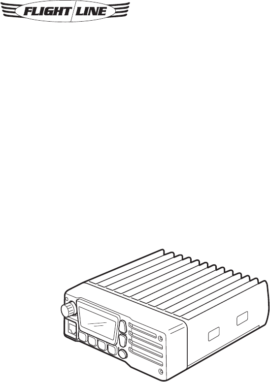
VHF AIR BAND TRANSCEIVER
FL-M1000A/FL-M1000E
Instruction Manual

2
ATTENTION READ ME FIRST
FCC WARNING
Changes or modifications not expressly
approved by the party responsible for
compliance could void the user’s authority
to operate the equipment.
NOTICE:
This equipment has been tested and
found to comply with the limits for a Class
A digital device, pursuant to part 15 of
the FCC Rules. These limits are designed
to provide reasonable protection against
harmful interference when the equipment
is operated in a commercial environment.
This equipment generates, uses and
can radiate radio frequency energy and,
if not installed and used in accordance
with the instructions, may cause harmful
interference to radio communications.
Operation of this equipment in a
residential area is likely to cause harmful
interference in which case the user will be
required to correct the interference at his
own expense.
• Properly shielded a grounded cables
and connectors must be used for
connection to host computer and /
or peripherals in order to meet FCC
emission limits. (AC adaptor) with ferrite
core must be used for RF interference
suppression.
Notes to the Installer /
User.
• This is a 13.8-volt or 26.4-volt DC radio,
voltages greater than 33 volts DC or AC
voltage will severely damage it.
• When making adjustments to the
transmitter, ensure that you are not on
an occupied channel.
• Do not transmit on 121.500MHz, as this
is the international distress frequency.
• Do not transmit into an unterminated
antenna line as a suitable antenna must
be connected. Transmitting without
being connected to an antenna may
damage the radio.
• Ensure that the supply voltage is
regulated and does not fall below 11.7
volts DC or exceed 31 volts DC.
• The transceiver is not waterproof. Do
not allow it to get wet.
• Speaker impedance must be either 4 or
8 ohms (4 ohms preferred) at 10 watts.
• Use of electret microphones highly
recommended.
About this document.
Due to our policy of continuous
improvement to our products and
services, technical specifications and
claims are correct at time of going to
printing, however they are subject to
change without notice.
Flightline does not accept liability for any
error or omission.
This manual remains the copyright of
Flightline.

3
CONTENTS
INTRODUCTION ......................................4
Introduction ...............................................4
Part names and functions ........................5
MP-1000 microphone ...............................7
Display ......................................................8
Recalling the Pri channel ........................10
BASIC OPERATION ..............................11
Basic usage ............................................11
Turning the power on or off ....................12
Adjusting the audio volume ....................12
Adjusting the squelch level .....................13
Changing the channel .............................14
Change mHz/kHz for variable
frequency .............................................14
Dimmer ....................................................15
Transmitting ............................................15
MEMORY AND SCAN OPERATION .....16
Scanning the VFO frequencies ...............16
Scanning the memory.............................16
Scanning with the priority channel .........17
Priority watch ..........................................18
Other memory operations ......................19
MEMORY OPERATIONS ...................... 20
Memorizing a frequency .........................20
Switching the VFO and
memory mode .....................................20
Erasing a memory ...................................21
Setting the priority memory ....................21
Recalling the priority channel ................ 22
Naming the memory channel
(Memory tag) .......................................23
Setting the lockout memory channel .....24
ADVANCED OPERATION..................... 25
Emergency call .......................................25
Changing the settings .............................25
Changing the each settings ....................26
APPENDIX ............................................. 27
Connecting ..............................................27
Mounting ................................................ 29
Optional headset adapter ...................... 30
Specifications ........................................ 32
Frequency list (Example of frequency
versus display when using 8.33 Khz
step) .................................................... 33
Supplied accessories ............................ 34

4
INTRODUCTION
Introduction
Thank you for purchasing this quality
product from Flightline.
This transceiver has been designed and
manufactured in Japan. This is the best
product for vehicle working in the Airport.
Ease of operation was another primary
achievement.
Please follow this manual closely to
ensure optimum performance, we do
hope you have many hours of trouble free
communication.
Installation instructions
This manual contains all of the necessary
instructions for installation and operation.
After installation please keep this manual
in a safe place for future reference.
Installation considerations
As with all air Air Band radios, successful
communications start with the installation.
After unpacking the transceiver verify all
parts against the parts list. The Display
provides a 30-degrees field of view
from right and left, and from upper side.
However from the down side, it is out of
guarantee.
Please be careful when install this
product.
The use of aviation quality shielded cable
is recommended at all times.
Avoid running or wrapping other wires
around the antenna lead and keep lengths
as short as reasonably possible. Ensure
that the radio is not exposed to direct rain
or moisture (we do not accept liability for
water damage).
Make sure the transceiver is connected
to a 11.7-16.8 volt or 23-31 volt battery
system.
Do not use AC volts from a Rotax lighting
coil.
About this product
This product is Air Band Land Mobile
Radio designed for vehicle, not for
Aircraft.
The radio can be operated with Hand
Microphone or Headset. You can choose
audio output from External Speaker and/
or Headphone.
The radio has various built-in Scan
function.
5
INTRODUCTION
Part Names and Functions
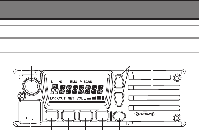
Front panel
kHz
FL-M1000
PWR
SQL
V/M
SCAN
PRI
: @ ;.
8 2 > B =
q TX/RX indicator
• Indicate Red in transmission, Green in
Receiving.
w Rotary Encoder
• Change the operating Frequency or
Memory Channel.
• Turning this Encoder while pausing
scan resumes the Scan mode.
• LCD Backlight will be ON by short
press.
• Available to change the tuning range by
Long Press.
e Volume button
• The audio volume will be up or down.
r Internal Speaker
• Internal Speaker.
• The audio output is available to change
to Headphone.
t PWR button
• Short press: indicates voltage of power
source.
• Long press: turn the radio ON/OFF.
y SQL button
• Available to change the Squelch setting.
u PRI button
• Short Press: recall the Priority Channel.
• Long Press: recall the Emergency
Channel..
i SCAN button
• Short Press: start SCAN function.
• Long Press: start Dual Watch function.
o V/M button
• Short Press: switch between Memory
mode and VFO mode.
• Long Press: Add memory current
channel.

6
INTRODUCTION
!0 Microphone connecter
• Connect the supplied Microphone
(do not connect other microphone to
prevent trouble)
7
INTRODUCTION
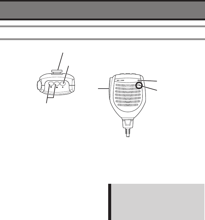
MP-1000 Microphone
=
;
@
B
.
:
q Volume UP/DOWN
• Decrease audio volume by press the v
button, and increase by c button
w Monitor Button
• Press the button makes the radio in
monitor mode.
e PTT (Push To Talk)
• Press the button makes the radio to
transmit mode, and release to receive
mode.
r Microphone
• Speak into the circled area when
talking.
Note:
There is a microphone element in the
circled area. The sound becomes
unclear if it doesn’t speak toward the
circled part.
t Busy Indicator (Green)
• It will become Green while somebody is
talking, or squelch is open.
y Hanger
• It is a metal hanger to hook the
microphone.
8
INTRODUCTION
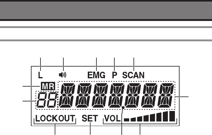
Display
> 2 8
=;.@:
B
q Low battery indicator
• The “L” will indicate when the voltage of
power source becomes less than 11.7
Volt.
w Busy indicator
• The Busy icon will indicate when
receiving.
e Emergency indicator
• The “EMG” icon will indicate when
recall the Emergency channel.
r Priority Watch indicator
• The “P” icon will indicate when the
radio is in Priority Scan or Priority watch
mode.
t Scan indicator
• The “SCAN” icon will indicate when the
radio is in SCAN mode.
y Memory indicator
• The “MR” icon will indicate when the
radio is displaying a memory channel.
u LOCKOUT indicator
• The “LOCKOUT” icon will indicate when
the channel is not in the SCAN LIST.
i Setting mode indicator
• The “SET” icon will indicate when the
radio is in SETTING mode.
o Volume level indicator
• It indicates the Audio Volume Level.
!0 Memory number indicator
• It shows memory number or “Pr” as
priority.
!1 Main indicator
• It shows frequency and/or setting etc..
!2 Decimal point indicator
• It indicates “dot” at decimal point.
9
INTRODUCTION
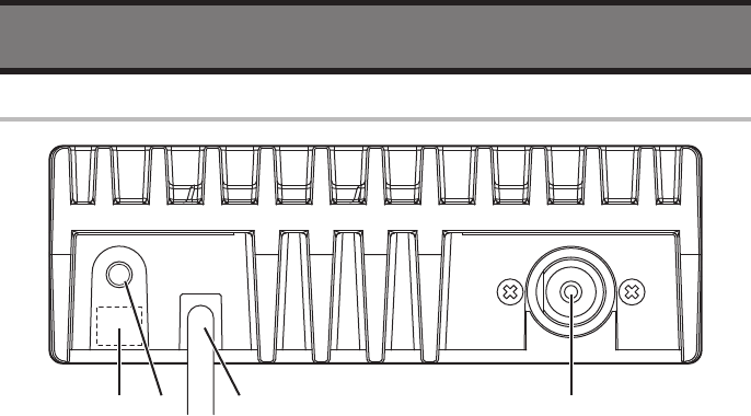
Rear panel
:@; .
q Antenna Connector
• Connect an Antenna with PL-259 type
(50 ohms, SWR: less than 3.0)
w Power Cable
• Connect a Battery (12 V or 24 V). Do not
connect the other type.
e External Speaker Jack
• Connect a Speaker with more than 10 W,
8 ohms.
r Optional Jack
• Connect a Headset (supplied by 3rd
party)
Please contact your dealer if you have any
question.
10
INTRODUCTION
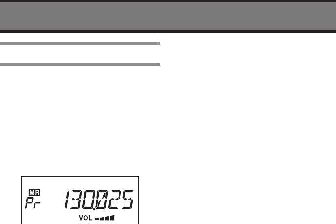
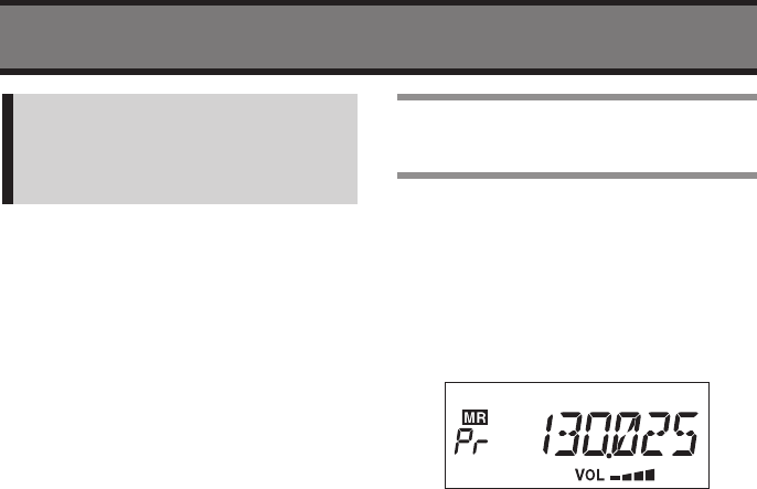
Recalling the Pri Channel
You can recall a Priority Channel by
pressing the PRI button when the radio
is in VFO mode or in Memory Channel
mode.
1 Press the PRI button
• The channel will be changed to
Priority Channel and the “Pr” will be
displayed instead of memory channel
number.
2 Press the PRI button again to return
to previous channel
11
BASIC OPERATION
Basic Usage
1 Press the PWR button more than
two seconds.
2 Adjust the audio level by Volume
button.
3 Press the SQL button to adjust the
Squelch level.
4 Turn the Rotary Knob slowly
direction to clockwise until noise
disappear.
5 Press the SQL button to save and
exit the adjustment.
6 Turn the Rotary Knob to select
desired frequency.
• The TX/RX Indicator will become
Green if the radio receives a signal.
7 Wait a signal from transmitting your
partner.
8 Monitor the frequency is not busy
before transmission.
9 Hold the microphone about 1 to
3cm away from your mouth.
10
Speak slowly and clearly into the
microphone with press and hold
the PTT switch.
• The TX/RX Indicator on the radio will
become Red while transmitting.
BASIC OPERATION
12
Turning the Power On or
Off
1 Press and hold the PWR button
more than two seconds to turn the
radio ON.
• The LCD will be activated and
Frequency will be displayed on the
LCD.
2 Press and hold the PWR button
more than two seconds to turn the
radio OFF.
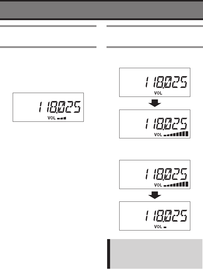
Adjusting the Audio
Volume
1 Press the c button to increase
audio level.
2 Press the v button to decrease
audio level.
Note:
The audio level will be continuously
changed by Press and hold the
buttons.
13
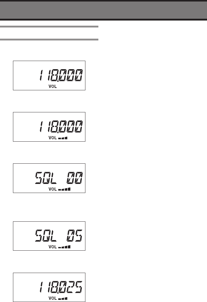
BASIC OPERATION
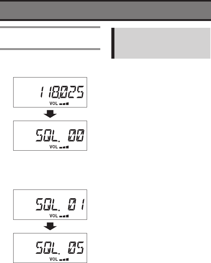
Adjusting the Squelch
Level
1 Press the SQL button
• The Display will change to Squelch
Setting mode.
2 Turn the Rotary Knob slowly
direction to clockwise.
3 Stop turning the Knob when Noise
disappears.
4 Press the SQL button to save and
exit the Squelch adjustment.
• The Display will return to previous
state.
Note:
The audio will be muted when
receiving week signal if the SQL level
is set too big.
You can change Audio level while in
Squelch Setting mode.
BASIC OPERATION
14
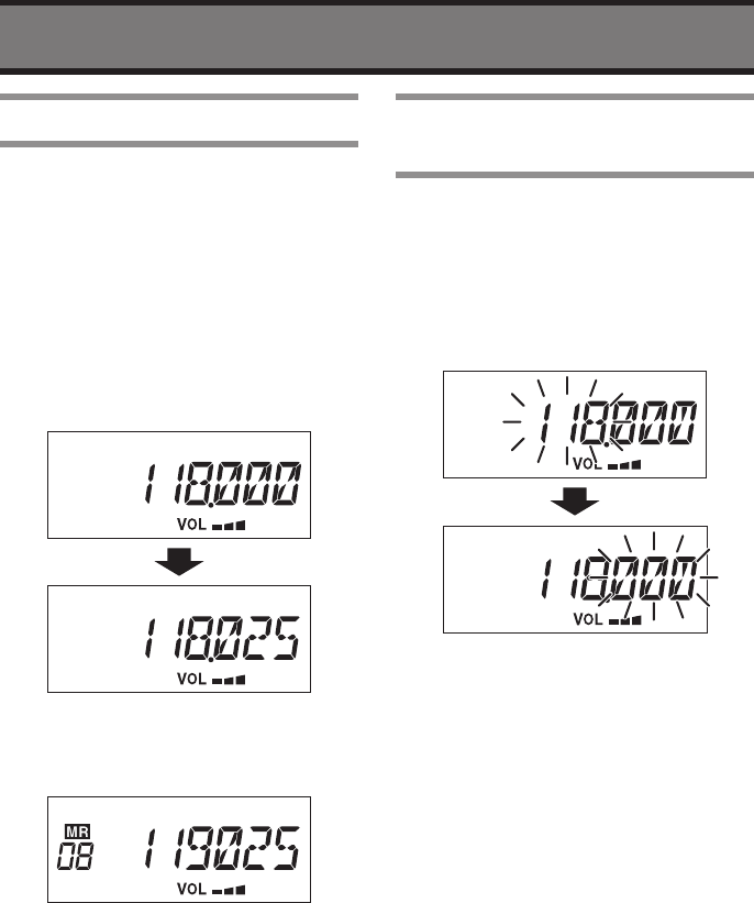
Changing the Channel
Frequency on the LCD will be changed
by turning the Rotary Knob in VFO mode.
Channel Number on the LCD will be
changed by turning the Rotary Knob in
Memory mode.
1 Confirm the VFO mode before
changing Frequency.
• There is no “MR” icon in VFO mode.
2 Turn the Rotary Knob to change
desired frequency.
3 Press the V/M button to switch
between VFO mode and Memory
mode.
• There is “MR” icon in Memory mode.
4 Turn the Rotary Knob to change
desired Memory number.
• See page 20 how to memorize a
frequency.
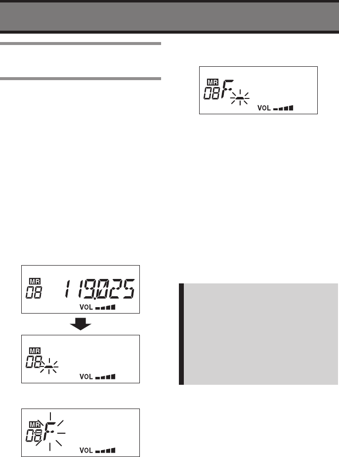
Change MHz/kHz for
Variable Frequency
You can switch between MHz and kHz for
changing frequencies in VFO mode.
1 Confirm the radio is in VFO mode.
2 Press and hold the Rotary Knob
more than one second.
• The variable part will be flashing.
15
BASIC OPERATION
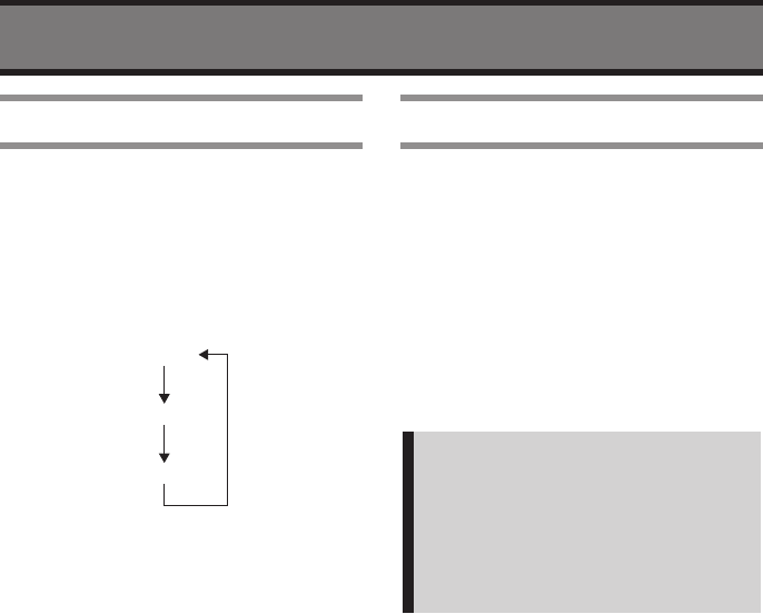
Dimmer
The brightness of LCD Backlight can be
changed.
1 Confirm the radio is switched ON.
2 Short press the Rotary Knob.
• The brightness will be changed as
follows.
Normal
Dark
OFF
Transmitting
1 Confirm that the channel is not
busy before transmitting.
2 Keep away your mouth from the
microphone about one inch.
3 Press and hold the PTT switch.
4 Speak slowly and clearly into the
microphone.
• The RX/TX Indicator on the radio will
become Red.
Note:
There is a function “Timeout Timer” in
this radio. The continuous transmitting
will be automatically stopped for 3
minutes as default. The Timeout Timer
can be selected from Off, 1, 3 and 5
minutes. (see page 25 or 26)
16
MEMORY OPERATION
There are various functions such as
Frequency Scanning on VFO mode,
Memory Scanning on Memory mode or
dual watch the specific two frequencies.
Scanning the VFO
Frequencies
It is Scanning for all available frequencies
when the radio is in VFO mode.
1 Confirm the radio is in VFO mode.
2 Confirm the radio is not receiving
on current channel.
3 Press the SCAN button.
4 The radio starts Scanning.
VFO Scan
Skip (25 kHz or
8.33 kHz step)*
The Frequency Step
should be set by dealer
118.00 MHz
136.975 MHz
• If the radio receives a signal during
Scan, the radio will pause the
scanning on the channel.
5 Press the SCAN button to stop the
Scanning.
* Except USA Version.
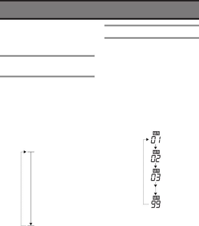
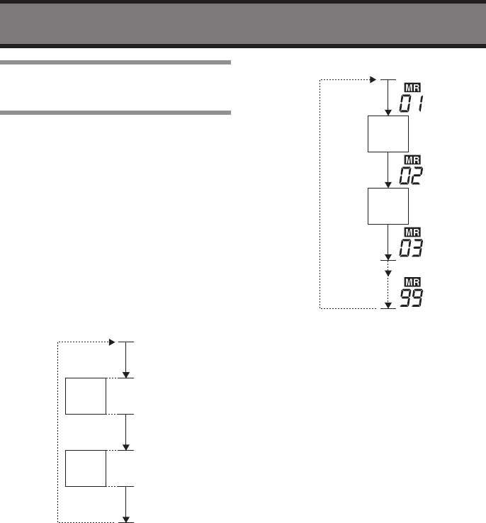
Scanning the Memory
This function is Scanning for memorized
channels. Please refer page 20; how to
memorize a frequency.
1 Confirm the radio is in VFO mode.
2 Press V/M key to change to
Memory mode.
3 Confirm the radio is not receiving
on the current channel.
4 Press the SCAN button.
5 You can see the radio is scanning.
Memory scan
• If the radio receives a signal during
Scanning, the radio will pause the
scanning on the channel.
6 Press the SCAN button to stop the
Scanning.
17
MEMORY OPERATION
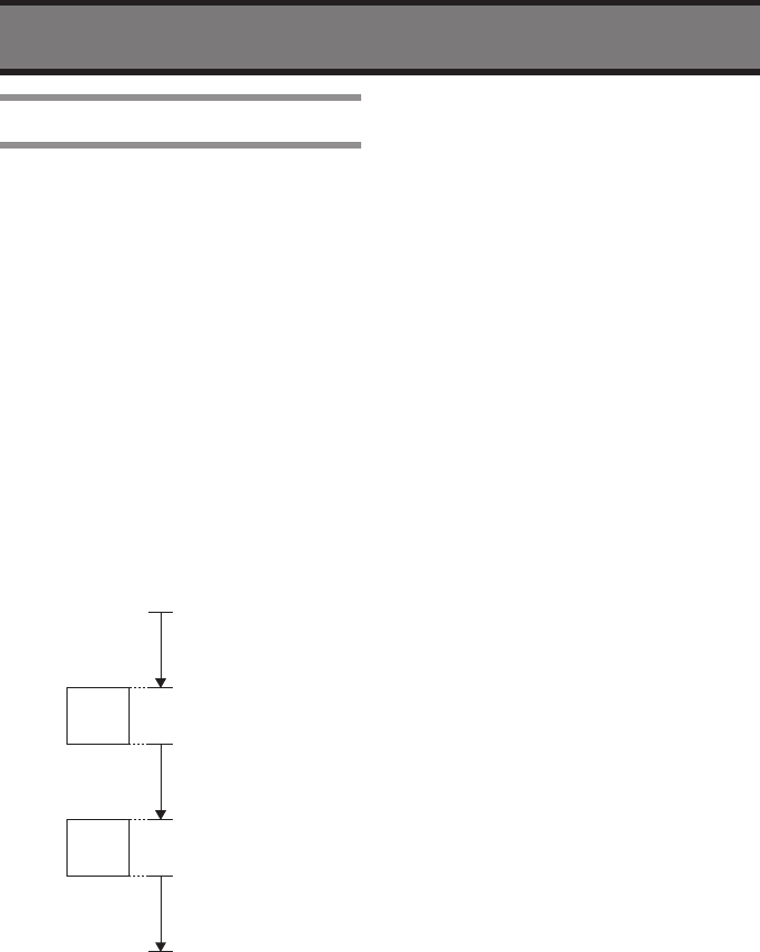
Scanning with the Priority
Channel
The Priority Channel will be checked
every 250 msec during the radio is in VFO
scanning or Memory Scanning.
1 Confirm the radio is in VFO mode or
Memory mode.
2 Confirm the radio is not receiving
at the current channel.
3 Press the SCAN button.
4 Confirm the radio starts the
Scanning.
Priority VFO Scan
Skip
118.00 MHz
136.975 MHz
250 ms
250 ms
250 ms
250 ms
Pri Ch
Pri Ch 250 ms
Priority Memory Scan
Skip
250 ms
250 ms
250 ms
250 ms
Pri Ch
Pri Ch 250 ms
• If the radio receives a signal during
Scan, the radio will pause the
scanning on the channel.
• The priority channel will be checked
every 5 seconds even if the radio is
receiving.
• The radio will pause the scanning
if receiving a signal on the Priority
Channel.
5 Press the SCAN button to stop the
Scanning.
18
MEMORY OPERATION
Priority Watch
The “Priority Watch” is to watch the
current channel (displayed frequency or
memory channel) and Priority Channel
alternately.
1 Confirm the radio is in VFO mode or
Memory mode.
2 Select a desired frequency or
memory channel to make the
Priority Watch.
3 Confirm the radio is not receiving
at displayed channel.
4 Press and hold the SCAN button
until the “P” icon will appear on the
LCD.
5 Confirm the radio starts the
“Priority Watch”.
VFO or Memory
250 msec
VFO or Memory
250 msec
VFO or Memory
250 msec
250 ms
Pri Ch
Pri Ch 250 ms
• If the radio receives a signal during
Scan, the radio will pause the
scanning on the channel.
• The priority channel will be checked
every 5 seconds even if the radio is
receiving.
• The radio will pause the scanning
if receiving a signal on the Priority
Channel.
6 Press the SCAN button to stop the
“Priority Watch”.

19
MEMORY OPERATION
Other Memory Operations
There are advanced feature for Scanning,
On hook scanning and Lock Out Memory.
On hook scanning, Lock Out Memory
• On hook scanning
The Scan will start when the
microphone is ON Hook, and will stop
when OFF Hook.
In order to use this function, the Hook
function must be enabled in the User
Setting mode. Beside the microphone
hook must be connected with ground
level (Earth). If the microphone hook
is not connected to Earth, the Hook
function does not work.
• Lock Out Memory
It is able to delete the channel from
the Scan list to skip the channel during
Scanning.
20
MEMORY OPERATIONS
This section shows how to memorize
frequently using frequency as Memory
Channel.
Memorizing a Frequency
1 Select a frequency that is going to
memorize by rotary knob in the VFO
mode.
2 Press and hold the V/M button
more than two seconds.
• The “MR” icon will appear and
Memory Number will flash.
3 Select desired number by rotary
knob.
• The “MR” icon will not appear at
the memory number that is not
memorized a frequency.
4 Press and hold the V/M button
more than 2 seconds to save and
exit.
• The display will return to VFO mode.
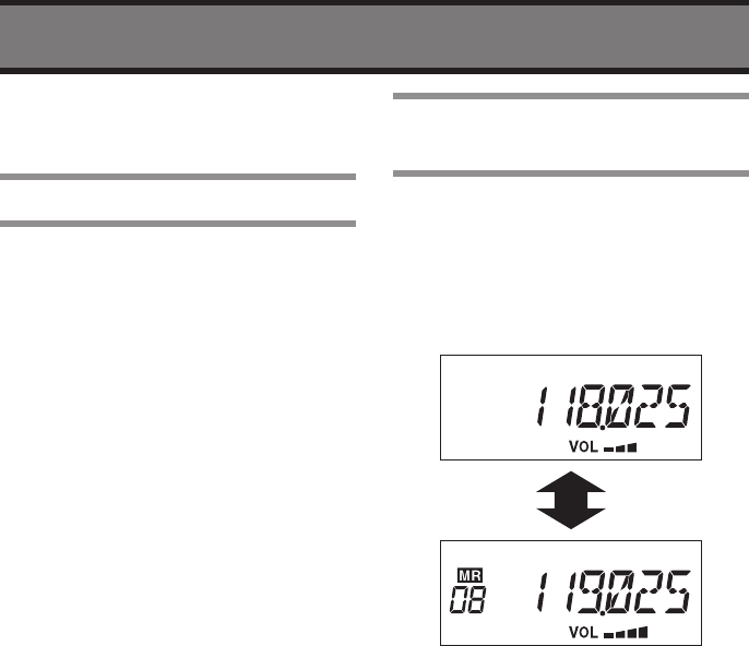
Switching the VFO and
Memory Mode
The operating mode can be changed
between VFO mode and Memory mode.
1 Press the V/M button.
• The operating mode will switch VFO
mode and Memory mode every
pressing the V/M button.
21
MEMORY OPERATIONS
Erasing a Memory
The memorized frequency can be erased.
1 Press and hold the V/M button
more than two seconds in VFO
mode.
• The “MR” icon will appear and
Memory Number will be flashing.
2 Select a number that you want to
erase by rotary knob.
• If frequency is memorized then “MR”
icon will appear.
3 Press and hold the SQL button
more than two seconds.
• The displayed frequency will
disappear.
4 Press and hold the V/M button
more than two seconds to save and
exit.
• The display will return to previous
VFO mode.
• If you want to exit without save the
erase information, then short press
the V/M button.
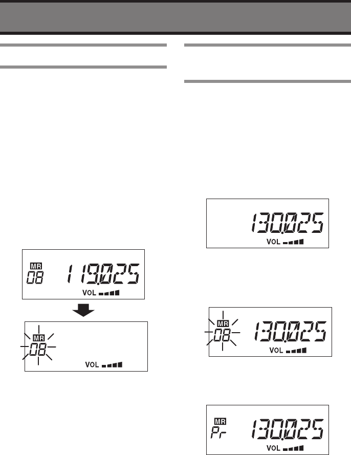
Setting the Priority
Memory
Memorize a frequency that is most
frequently using as Priority Channel. You
can recall the Priority Channel easily
by pressing the PRI button. The priority
channel will be used for the Priority Scan
or Priority Watch.
1 Select a frequency that you want
to make it as Priority Channel by
rotary knob in VFO mode.
2 Press and hold the V/M button
more than two seconds.
• The “MR” icon will appear and
Memory Number will be flashing.
3 Press the PRI button.
• The Memory Number will change to
“PR”.
4 Press and hold the V/M button
more than two seconds.
• The Display will return to VFO mode.
22
MEMORY OPERATIONS
Note:
It is available to memorize as priority
channel if displaying the “PR” by
turning the rotary knob at the step 3.
Recalling the Priority
Channel
The Priority Channel can be easily
recalled by just pressing PRI button even
when the radio is in VFO mode or Memory
Channel mode.
1 Press the PRI button.
• The “PR” will appear instead of
Memory Number.
2 Press the PRI button to return
previous display.
23
MEMORY OPERATIONS
Naming the Memory
Channel (Memory Tag)
You can name the memory channel.
The name will be displayed instead of
frequency when you recall the memory
channel if Memory Tag feature is enabled.
1 Press the V/M button during the
radio is in VFO mode.
• The “MR” icon and the Memory
Number will be displayed.
2 Select a Memory Number that you
want to make a Name Tag by rotary
knob.
3 Press and hold the V/M button
more than two seconds.
• The first digit will be flashing to input
first character.
4 Select a character by rotary knob.
5 Press the c button to move second
digit.
6 Enter the name tag by repeating the
step 4 and 5.
• It is available to enter maximum 6
characters.
If pressing the v button then the
entering digit will be backward.
7 Press and hold the V/M button
more than two seconds to save and
exit.
• If you want to exit without save the
tag information, then short press the
V/M button.
The radio will return to previous
condition.
Note:
• You can use following characters as
the Name Tag;
0 to 9, A to Z, /, _, ., +, *, <, >, $, &
and Space
• To delete the Name Tag, select the
named memory number then press
and hold the SQL button more than
two seconds.
24
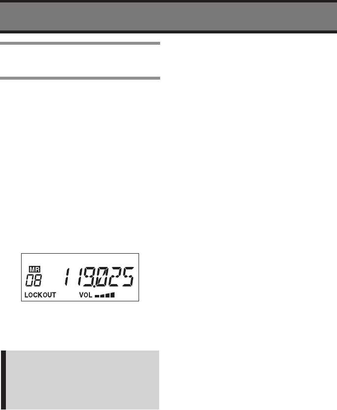
MEMORY OPERATIONS
Setting the Lockout
Memory Channel
This section indicates how to delete
(lockout) a memory channel from the
memory scan list.
1 Press the V/M button during the
radio is in VFO mode.
• The “MR” icon and the Memory
Number will appear on the LCD.
2 Select a Memory Number that you
want to skip for Memory Scan by
rotary knob.
3 Press and hold the Rotary Knob
more than two second.
• The “LOCKOUT” icon will appear on
the LCD.
4 Press the V/M button to exit.
• The radio will return to previous VFO
mode.
Note:
If you want to cancel the Lockout,
then press and hold the rotary knob
more than two seconds at the step 3.
The “LOCKOUT” icon will disappear.
25
ADVANCED OPERATION
Emergency Call
It is easily recall an Emergency Channel
(121.5MHz) when the radio is in VFO
mode, Memory mode and on the Priority
Channel.
1 Press and hold the PRI button more
than two seconds.
• The “EMG” icon and frequency
“121.5MHz” will be displayed on the
LCD.
2 Press and hold the PRI button to
return previous display.
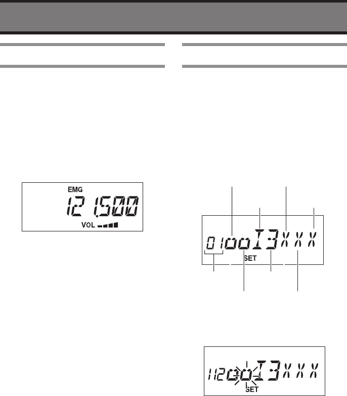
Changing the Settings
The following functions can be changed;
Beep tone, External speaker setting,
Internal speaker setting, Time out timer,
Busy lockout, Memory tag, On hook
1 Turn the radio ON with press and
holding the V/M and SQL button.
• The “SET” icon with setting status will
be displayed.
Setting
number
Beep tone
Extermal
speaker
Internal
speaker
Time out
timer
Busy lock
Memory
tag
On hook
2 Select a desired function that you
want to change by rotary knob.
• The selected item will be flashing.
3 Press the rotary knob to change
the value.
4 Turn the radio OFF after the
changing completed.
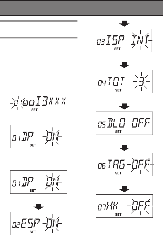
26
ADVANCED OPERATION
Changing the Each
Settings
The each setting can be changed
individually.
1 Turn the radio ON with press and
holding the V/M and SQL buttons.
• The “SET” icon with setting status will
be displayed.
2 Select the setting number (and the
number becomes flashing).
3 Press the rotary knob.
• The individual setting will displayed.
4 Press the rotary knob to get desired
change.
Beep tone
External speaker setting
Internal speaker setting
Time out timer
Busy lock out
Memory tag
On hook function
5 Turn the radio OFF after the
changing completed.
27
APPENDIX
Please contact your dealer about installation.
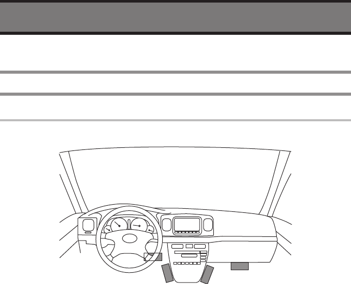
Connecting
Installing place
The radio must not be installed in the place where driving is obstructed.
28
APPENDIX
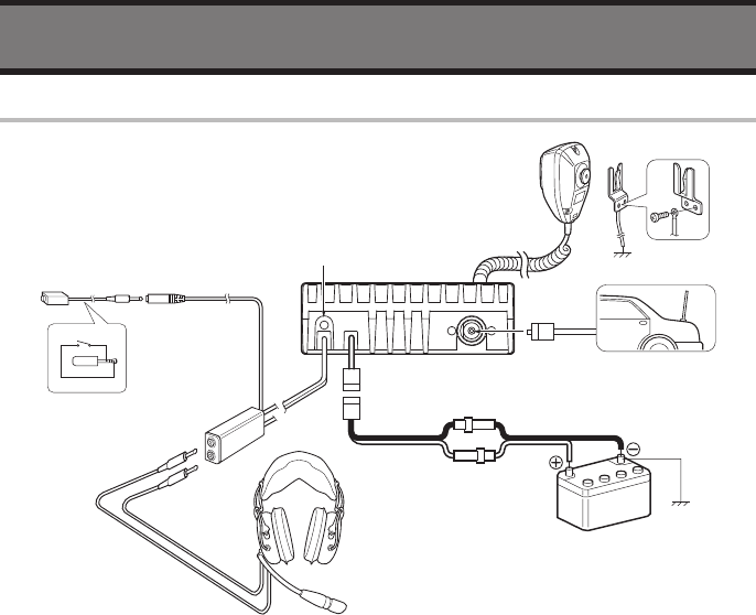
Connections
:
@
=
.
;
q Connect an Antenna and the Antenna Connector
• The Antenna that has PL-259 type connector (50homs, SWR: less than 3) is available
to connect.
w Connect Power Cable to Battery of the vehicle
• The available voltage of the Battery is 12V or 24V, do not connect the other type.
e Connect a Speaker (3rd party’s one) to External Speaker Jack
• The available impedance of the speaker is 8 ohms, and the rated input power must be
more than 10 W.
r Connect the Headset (supplied by 3rd party) to Optional Jack.
t Connecting the Microphone hanger to earth of the vehicle
enables Microphone Hanger function.
29
APPENDIX
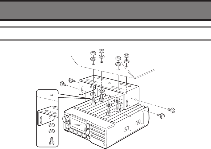
Mounting
The radio can settle on/under the dashboard using supplied bracket.
• The bracket must be fixed with supplied screws.
• Otherwise the bracket cannot be fixed tightly or inside of the radio may get serious
damage.
30
APPENDIX
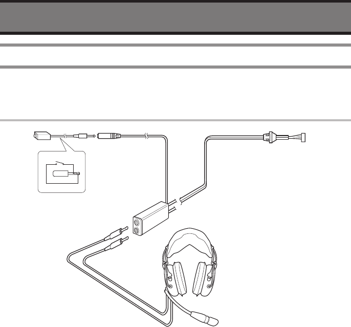
Optional Headset Adapter
When using an optional headset, such as those from the David Clark Co. via the adapter,
the transceiver outputs your transmitted voice to the headset for monitoring.
Connection
HEADSET
(Must be purchased separately.)
PTT switch
Use a PTT switch
with a 3.5 mm
diameter plug,
if required.
31
APPENDIX
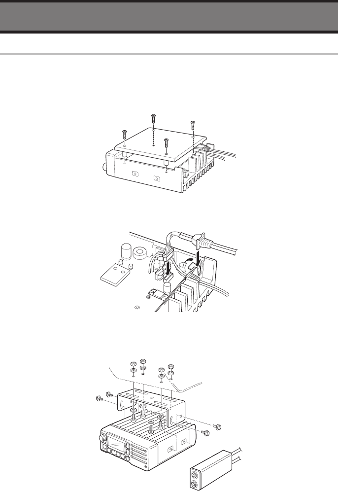
Installation
The optional HEADSET ADAPTER install as follows.
q Turns the power OFF, then disconnect the DC power cable.
w Unscrew the 4 screws, then remove the bottom cover.
e Insert the connector as shown below.
r Mount the phone plug attachment together with the mobile
mounting bracket with 2 supplied screws.

32
APPENDIX
Specifications
General
Frequency range: ....................................... 118.000 to 136.975 MHz
Channel spacing: .......................................*8.33 kHz / 25 kHz
Mode: ......................................................... AM (6K00A3E)
Number of memory channels: ...................99
Acceptable power supply: .........................13.8 V or 26.4 VDC (Negative ground only)
Usable temp. range: ..................................-30 °C to +60 °C
Frequency stability: ...................................+/- 5 ppm
Current drain: .............................................TX: 6 A (max), RX: 6 A (max), Standby: 260 mA
Dimensions: ............................................... W 150 X D 190 X H 50 (mm)
Weight: ....................................................... 1700 g
Transmitter
Output power: ............................................9 W (carrier) typical, 36 W (P-P)
Modulation: ................................................ Last stage modulation
Modulation limiting: ................................... 70 to 100%
Audio harmonics distortion: ...................... Less than 15% (at 85% modulation)
Hum and noise ratio: .................................More than 40 dB
Spurious emissions: ..................................-16 dBm or less
Antenna impedance: ..................................50 Ω
Receiver
Receive system: .........................................Double conversion superheterodyne
Intermediate frequency: .............................1st : 38.85 MHz (Upper) 2nd : 450 kHz (Lower)
Sensitivity (at 6dB S/N): ............................Less than 1uV
Squelch sensitivity: ....................................0.5uV (Threshold)
Selectivity
25 kHz channel spacing: .....................More than ±8 kHz (at 6 dB)
Less than ±25 kHz (at 60 dB)
*8.33 kHz channel spacing: ................. More than ±2.778 kHz (at 6 dB)
Less than ±7.37 kHz (at 60 dB)
Spurious response rejection: ....................More than 60 dB
Audio output power: ..................................More than 15 W (at 4 Ω)
Side tone: ...................................................More than 100 mW (at 600 Ω)
Hum and noise: ..........................................More than 25 dB
Audio output impedance: ..........................External. Speaker 4 Ω (4 to 8 Ω)
Side tone 600 Ω
* Except USA version
33
APPENDIX
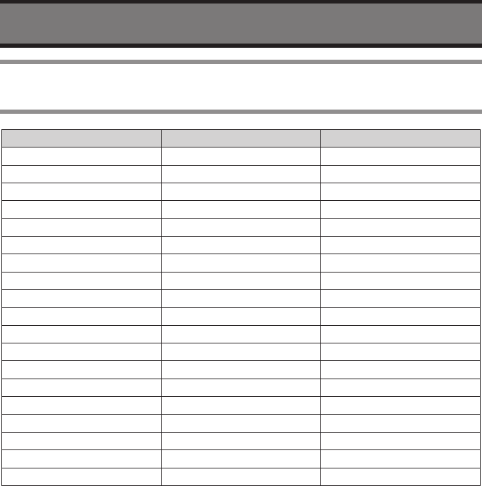
Frequency List (Example of Frequency Versus Display
when Using 8.33 kHz Step)
Operating Frequency Channel speacing (kHz) Displayed Frequency
118.00000 25 118.000
118.00000 *8.33 118.005
118.00833 *8.33 118.010
118.01667 *8.33 118.015
118.02500 25 118.025
118.02500 *8.33 118.030
118.03333 *8.33 118.035
118.04167 *8.33 118.040
118.05000 25 118.050
118.05000 *8.33 118.055
118.05833 *8.33 118.060
118.06667 *8.33 118.065
118.07500 25 118.075
118.07500 *8.33 118.080
118.08333 *8.33 118.085
118.09167 *8.33 118.090
118.10000 25 118.100
118.10000 *8.33 118.105
etc
The display at 136.9750MHz (with 8.33 kHz step) will be “136.980”.
* Except USA Version.

34
APPENDIX
Supplied Accessories
(1) MP1000 Microphone .......................................................................................... 1
(2) Microphone hanger and screw set ..................................................................... 1 set
(3) Microphone cable ............................................................................................... 1
(4) DC power cable (3 m(1 ft))with 10A Fuse .......................................................... 1
(5) Mounting bracket kit ........................................................................................... 1
Mounting bracket ................................................................................................ 1
Bracket bolt ......................................................................................................... 4
Mounting screw ................................................................................................. 4
Self-tapping screw ............................................................................................. 4
Flat washer .......................................................................................................... 4
Spring washer ..................................................................................................... 4
Nut ....................................................................................................................... 4

Limited liability warranty
Flightline warrants this product to be free from defects in materials and workmanship
for 1 year from the date of purchase or the minimum period described by applicable
consumer law.
If the unit is installed by an organization which holds an avionics installation approval
from the FAA, and that organization has co-signed and dated the warranty card, the
warranty period shall be deemed to commence from the date of installation.
The customer shall be responsible for any transportation costs for return of this product
to Flightline.
This warranty does not cover failures due to abuse, misuse, accident, unauthorized
alteration, or repairs carried out by parties other than Flightline or an approved Flightline
service center. This warranty does not cover failures where the product has not been
installed or operated, in accordance with the provisions of the User and Installation
manual(s).
It shall be at Flightline sole discretion to decide if a defect is a result of material or
workmanship failure.
T H E WA R R A N T I E S A N D R E ME D I ES C O N TA I NE D H ER E I N
ARE EXCLUSIVE AND IN LIEU OF ALL OTHER WARR ANTIES
EXPRESSED OR IMPLIED, INCLUDING ANY LIABILITY ARISING
UNDER WARRANTY OF MERCHANTABILITY OR FITNESS FOR
A PARTICULAR PURPOSE, STATUARY OR OTHERWISE. THIS
WARRANTY GIVES YOU SPECIFIC LEGAL RIGHTS, WHICH MAY
VARY FROM STATE TO STATE, AND COUNTRY TO COUNTRY.
IN NO EVENT SHALL FLIGHTLINE BE LIABLE FOR ANY INCIDENTAL,
SPECIAL, INDIRECT OR CONSEQUENTIAL DAMAGES, WHETHER
RESULTING FROM THE USE, MISUSE OR INABILITY TO USE THIS
PRODUCT OR FROM DEFECTS IN THE PRODUCT.
Flightline may at it discretion, refer product returns for repair or service, to a service
facility closest to you. Flightline reserves the right to repair or replace the unit or software
or offer a full refund of the purchase price at it’s sole discretion.
SUCH REMEDY SHALL BE YOUR SOLE AND EXCLUSIVE REMEDY FOR ANY BREACH
OF WARRANTY.
Supplied by
Flightline 2009
All Rights Reserved
Printed in Japan April 2009 00M70AC851010
Flightline
12830 E. Mirabeau Parkway
Spokane Valley, WA 99216
Toll free tel.: 1-800-235-3300
Toll free fax: 1-800-828-0623
http://www.edmo.com