ELANsat Technologies AV-101R Wireless A/V System Receiver (Control Signal Tx) User Manual AVC S101 6060407100 10
ELANsat Technologies Inc. Wireless A/V System Receiver (Control Signal Tx) AVC S101 6060407100 10
Prelim Manual
Wireless System
Wireless System
2.4GHz
2.4GHz
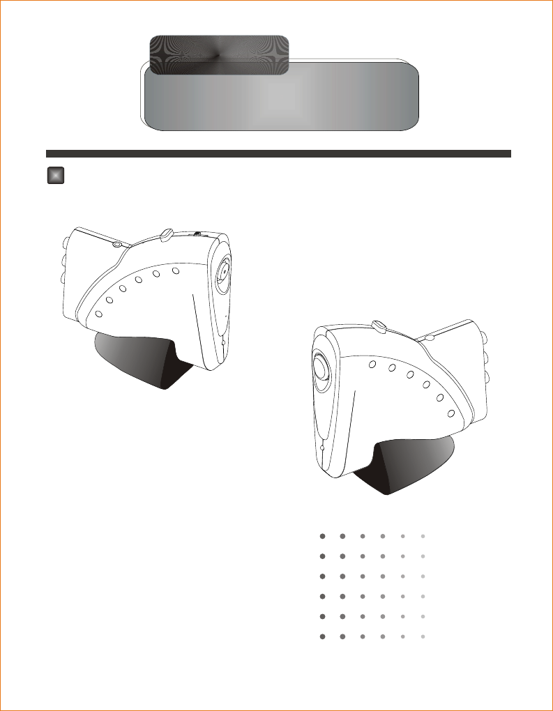
2.4 GHz Wireless Audio/Video System
1. INTRODUCTION1. INTRODUCTION
2. PACKAGE CONTENTS2. PACKAGE CONTENTS
3. CONTROLS3. CONTROLS
4. SYSTEM INSTALLATION4. SYSTEM INSTALLATION
1
3
3
4
5
6. TROUBLE SHOOTING6. TROUBLE SHOOTING 7
5. OPERATION5. OPERATION
Built-in Color CMOS Camera

CAUTION
RISK OF ELECTRONIC
SHOCK DO NOT OPEN
CAUTION:
DO NOT REMOVE THE COVER FOR REDUCING THE RISK OF ELECTRIC SHOCK.
NO USER-SERVICEABLE PARTS INSIDE REFER SERVICING TO QUALIFIED SERVICE PERSONNEL.
GENERAL SAFETY SUMMARY
WARNING
To prevent fire or shock hazard , do not expose the unit to rain or moisture.
IMPORTANT SAFETY INSTRUCTIONS
All the safety and operating instructions should be read before the product is operated.
The safety and operating instructions should be retained for future reference.
All warnings on the product and in the operating instructions should be adhered to.
All operating and use instructions should be followed.
Unplug this products from the wall outlet before cleaning. Do not use liquid cleaners
or aerosol cleaners. Use a damp cloth for the cleaning.
Do not use attachments not recommended by the products manufacturer if they may
cause hazards.
Do not use this product near water - for example, near a bath tub, wash bowl, kitchen
sink, or laundry tub, in a wet basement, or near a swimming pool; and the like.
Any mounting of the product should follow the manufacturer's instructions, and should
use a mounting accessory recommended by the manufacturer.
.
This product should be operated only from the type of power source indicated on the
marking label. If you are not sure of the type or power supply to your home, consult your
product dealer or local Power Company. For products intended to operate from battery
power, or other sources, refer to the operating instruction.
.
Power supply cord should be routed so that they are not likely to be walked on or pinched
by items placed upon or against them, paying particular attention to cords at plugs, or
other sources, refer to the operating instructions.
1.
2.
5.
3.
4.
6.
7.
8.
9.
10.
Do not overload wall outlets, extension cords, or integral convenience receptacles as this
can result in a risk of fire or electric shock.
Unplug this product from the wall outlet and refer servicing to qualified service personnel
under the following conditions.
When the power- supply cord or plug is damaged.
If liquid have been spilled, or objects have fallen into the products
Never push objects of any kind into this product through openings as they may touch
dangerous voltage points or short-out parts that could result in a fire or electronic shock.
Never spill liquid of any kind on the product.
12.
13.
14.
When replacement parts are required, be sure the service technician has used replacement
parts specified by the manufacturer or that have the same characteristics as the original part.
Unauthorized substitutions may result in fire, electric shock, or other hazards.
Upon completion of any service or repair to this product ask the service technician to
perform safety checks to determine that the product is in proper operating condition.
The product should be situated away from heat sources such as radiators, heat registers,
stoves, or other products including amplifiers that produce heat.
15.
16.
17.
If the product does not operate normally by following the operating instructions, adjust only
those controls that are covered by the operating instructions as an improper adjustment of
other controls may result in damage and will often require extensive work by a qualified
technician to restore this product to its normal operation.
When the product exhibits a distinct change in performance - this indicates a need for
service.
If the products has been dropped or damaged in any way.
For added protection for this product during a lightning storm, or it is left unattended and
unused for long periods of time, unplug it from the wall outlet and disconnect cable system.
This will prevent damage to the product due to lightning and powerline surges.
11.

1. INTRODUCTION
Overview
Magic Audio/Video System built-in color CMOS Camera uses the
latest wireless technology to send stereo audio and video images
around your home. Watch your favorite TV programs or listen to
Hi-Fi quality stereo sound in any part of your home without cables
extended. CMOS Camera is as your baby sitter and security guard,
make you enjoy advanced technology and secure life.
Features
2.4GHz Wireless Sender and Receiver with 4 selectable
channels (DIP Switch)
Transmit the crisp Audio /Video signal with radio frequency.
Built-in microphone and color CMOS camera
Remote control the A/V source with IR Extender
Compatible with Camcorder or CMOS camera application
Low power consumption
NTSC/PAL video format available
Range up to 300 feet (L.O.S.)
Application
Home Security
Baby Monitor
Wireless A/V Entertainment
1
Antenna (2.4 G z) embedded in the housing
H
2
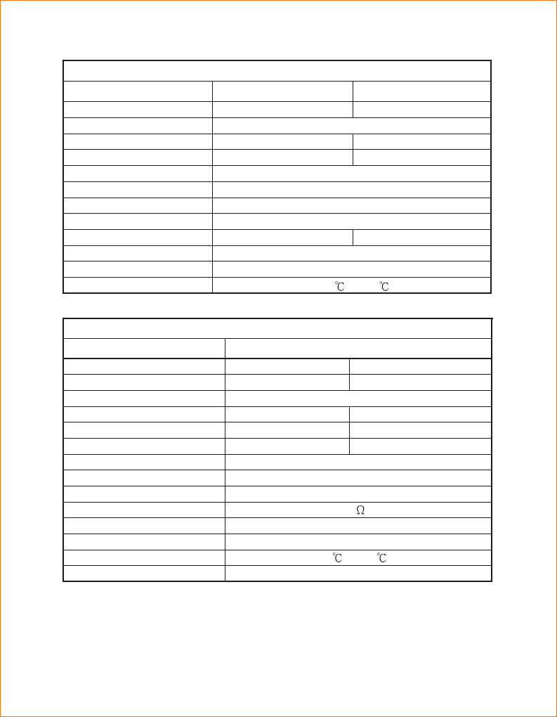
Specification
Characteristic
Model
Scanning System
Image Sensor
Efficiency Pixels
Horizontal Scan Frequency
Vertical Scan Frequency
Synchronize
Resolution
Min. Illumination
Video Output
Auto Electronic Exposure
Power Consumption
Operation Environment
Lens
2:1 Interlace 2:1 Interlace
NTSC PAL
1/3" CMOS Image Sensor
Wireless Camera - CMOS
510(H) X 492(V) 628(H) X 582(V)
15625Hz15750Hz
60Hz 50Hz
Internal
More than 230TV Lines
3LUX(F1.2)
1.0Vpp/75 composite
1/50 ~ 1/15000 seconds
35mA(200mW)
-10 ~ +50
F5.6 mm, F 2.0
Description
Frequency
Transmitter Power
Receiver Sensitivity
Channel Number
Frequency Stability
Audio / Video Input Level
Adaptor Power Supply
Power Consumption
Antenna
Dimension
Operating Environment
Characteristic
Model Sender Receiver
2.4GHz Wireless A/V Sender 2.4GHz Wireless A/V Receiver
10dBm(Typ.)
-85dBm(Typ.)
+ / - 100KHz (Typ.)
1 Vpp (Typ.)
9V ; 300mA
90mA (Typ.) 200mA (Typ.)
Dipole
-10 ~ +50
125 x 6 6 x 117 mm
4 (2414, 2432, 2450, 2468 M
Hz)
2400MHz ~2483MHz
3
2. PACKAGE CONTENTS
Check all of the components shown as below are included in box
before using.
Sender x 1
Receiver x 1
Infrared Extender x 1
Audio / Video Cable x 2
9V DC Power Adaptor x 2
1.
2.
3.
4.
5.
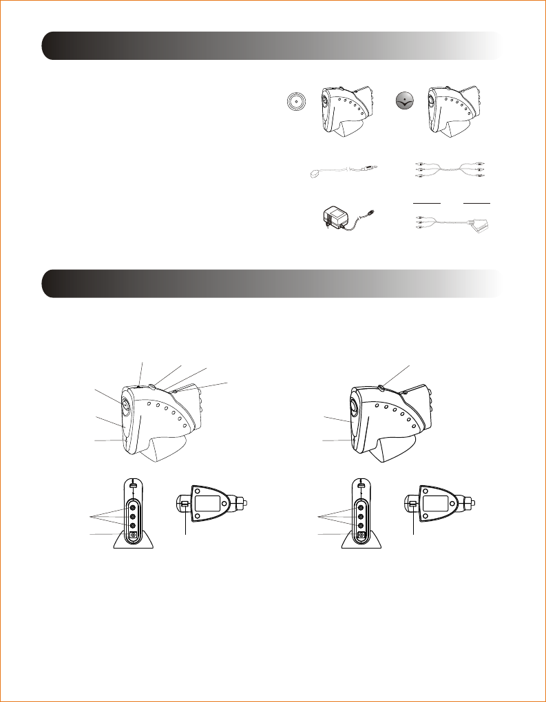
3. CONTROLS
Infrared Extender
Power Adaptor
RCA to RCA
OR
RCA to SCART
Sender Receiver
The Sender The Receiver
1.
2.
3.
4.
Power On/Off Button
LED Power Indicator
Microphone
5.
6.
7.
IR Extender Jack
Audio/Video Jack
Adaptor Jack
Channel Selector
Front & Side Panel
Rear & Bottom Panel
Front & Side Panel
Rear & Bottom Panel
IR Window
8.
9.
Slide switch for camera angle
Camera Lens
10.
Users Manual x 1
6.
2
8
11
3
2
5
6
4
7
9
10 11
9
10 11
Camera/AV sender switch
11.
4
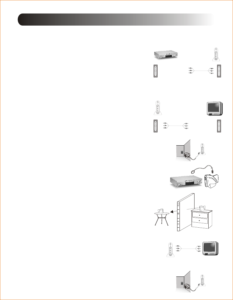
4. SYSTEM INSTALLATION
Connect the Sender to A/V Sources
external A/V OUTPUT jack with A/V cable.
Connect the Receiver to A/V Display
external A/V INPUT jack with A/V cable.
With power adaptors plug the Sender
and Receiver into standard electrical outlets.
Plug the IR Extender into the IR Extender
jack on the Sender; and place the IR Extender
in front of the A/V appliances which you want
to control.
1.
2.
3.
4.
Audio/Video Sender
Wireless Camera
Connect the Receiver to A/V Display
external A/V INPUT jack with A/V cable.
With power adaptors plug the Sender and
Receiver into standard electrical outlets.
1.
2.
3.
Put the Sender and Receiver on desk
or anywhere flat and convenient
in the house.
A/V Sources: Video Recorder, Digital Video Disc.,
Compact Disc Player, Satellite Receiver,
Camcorder, Stereo Receiver, Security Camera,
Hi-Fi System, Laser Disc Player, Computer,
Cassette Deck etc.
A/V Displays: Computer Monitor(Converted card
required ), Powered Speakers, TV Monitor etc.
Note: RCA to SCART Cable is used in Europe.
A/V Cable: RCA to RCA Cable or
RCA to SCART Cable.
Receiver A/V Display
Video in
Audio Left in
Audio Right in
Sender
A/V Source
Video out
Audio Left out
Audio Right out
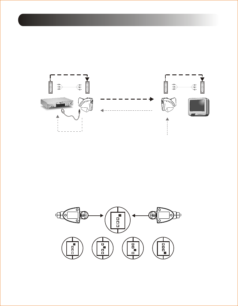
Room1
Room2
Sender
Receiver
5
5. OPERATIONS
Turn on the Sender and Receiver.
Turn on A/V sources and A/V display.
Adjust Channel Selectors on bottom of the Sender and
Receiver to the same channel.
Enjoy the wireless A/V entertainment.
Make sure the LED power indicators of Sender and Receiver
rightly light up.
1.
2.
3.
4.
5.
Audio/Video Sender
Video out
Audio Left out
Audio Right out
A/V Display
Video in
Audio Left in
Audio Right in
A/V Source Sender Receiver
2.4GHz Radio Frequency
A/V Signal
433MHz Radio Frequency
Remote Controller
IR
IR Extender
A/V Signal A/V Signal
For IR Control
Please note each Sender is set in channel one and Audio/Video
Sender mode when it is leaving factory.
Sender Receiver
ON DIP
1 2 3 4
ON DIP
1 2 3 4
ON DIP
1 2 3 4
ON DIP
1 2 3 4
ON DIP
1 2 3 4
Ch1 Ch2 Ch3 Ch4
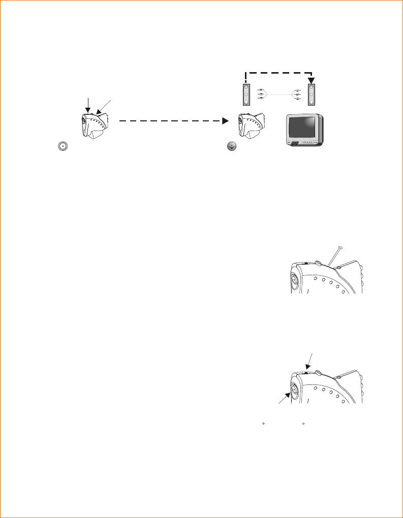
Slide switch for camera angle
Camera Lens Transmitter
Paper clip
Transmitter
Wireless Camera
Turn on the Sender and Receiver.
Make sure the LED power indicators of Sender
and Receiver rightly light up.
1.
2.
Slide the camera switch on top of
Sender to adjust lens to align
wherever you want to monitor and
get the best focus in image.
3.
Turn on A/V display.
4.
Adjust the Channel Selectors to the same channel.
7.Make sure the microphone built-in Sender work properly.
8.
Note: The operation temperature is from -10 C ~ +50 C.
Exchange Sender to Camera function by
a paper clip inserting and pressing into
the top small hole.
5.
A/V Display
Video in
Audio Left in
Audio Right in
Receiver
A/V Signal
2.4GHz Radio Frequency
A/V Signal
Camera/Sender
Slide the
camera angle Switch AV Sender
to Camera
6
7
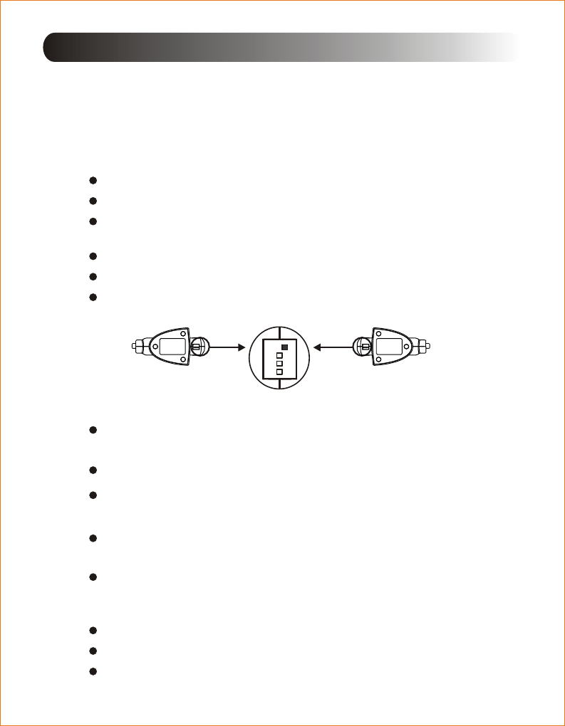
6. TROUBLE SHOOTING
Please read this user manual carefully before using the Wireless
Audio/Video System. If you still have difficulties to use the system,
consult the following syndrome, which will guide you to solve most
common problems.
No Pictures or Sound
Interference in the image and sound
Remote Control does not work properly
Check the adaptor rightly connected.
Power On/Off switch is in right position.
Check the A/V cable is inserted into the OUTPUT or INPUT
A/V jack accurately. (See page 4)
Move Sender or Receiver slowly to find a best
reception position for your A/V system.
Shorten the distance between Sender and Receiver.
Check if there is any interference radio frequency source
near the Receiver source, such as microwave oven.
If there is any interference radio frequency source near
Receiver, try to switch the channel to get a best performance.
Check Sender and Receiver at the same channel.
Check if the Remote Control is out of battery.
Make sure Remote Control align the Receiver IR window.
Make sure a proper distance between Remote Control and
Receiver IR window.
1.
2.
3.
Check all the cables well and rightly connected.
Check Sender and Receiver at the same channel.
Check A/V Sender and Camera switch completely.
Sender Receiver
EX: Switch Channel Selector to Ch1
ON DIP
1 2 3 4

Warning : Changes or modifications to this unit not expressly approved by the party
responsible for compliance could void the user authority to operate the equipment.
This device complies with Part 15 of the FCC Rules. Operation is subject to the
following two conditions: (1) this device may not cause harmful interference, and
(2) this device must accept any interference received, including interference that
may cause undesired operation.
The user manual or instruction manual for an intentional or unintentional radiator
shall caution the user that changes or modifications not expressly approved by the
party responsible for compliance could void the user's authority to operate the
equipment.
IR Extender
Item Transmitter Receiver
Frequency
Modulation
6 meters (min.)
-90dBm
30meters (typ.)
IR Operation Range
Transmitter
Power EIRP
Sensitivity
Receiving Range
from Tx
FSK
1/10 mW
(FCC/ CE & BZT)
433.92 MHz
Monopole
Antenna
Version 1.0
Audio/Video
2.4 GHz
2.4 GHz
WIRELESS
Camera+