ELCON Systemtechnik 6600 E-TRIP ® 6600 User Manual Mounting Manual
ELCON Systemtechnik GmbH E-TRIP ® 6600 Mounting Manual
UserManual.wiki
>
ELCON Systemtechnik
>
6600 User Manual
>
Mounting Manual
Contents
1.
Mounting Manual
2.
Operating Manual
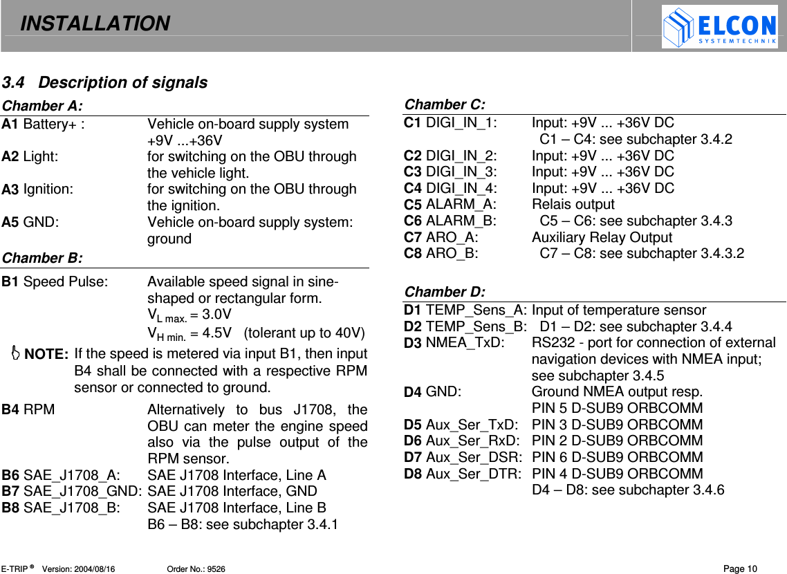
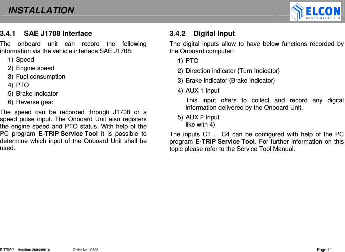
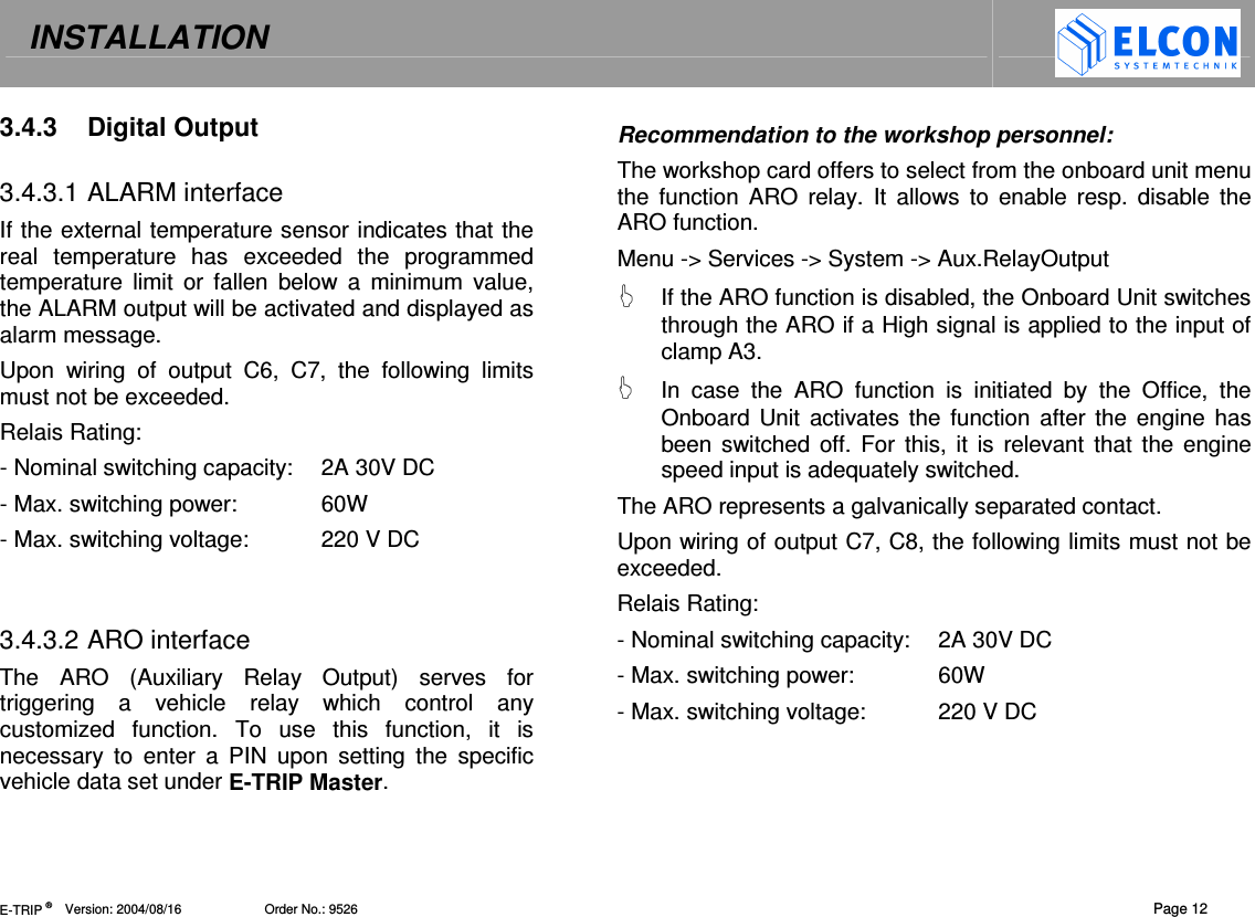
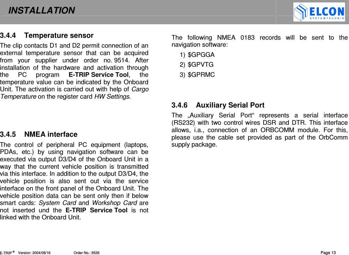
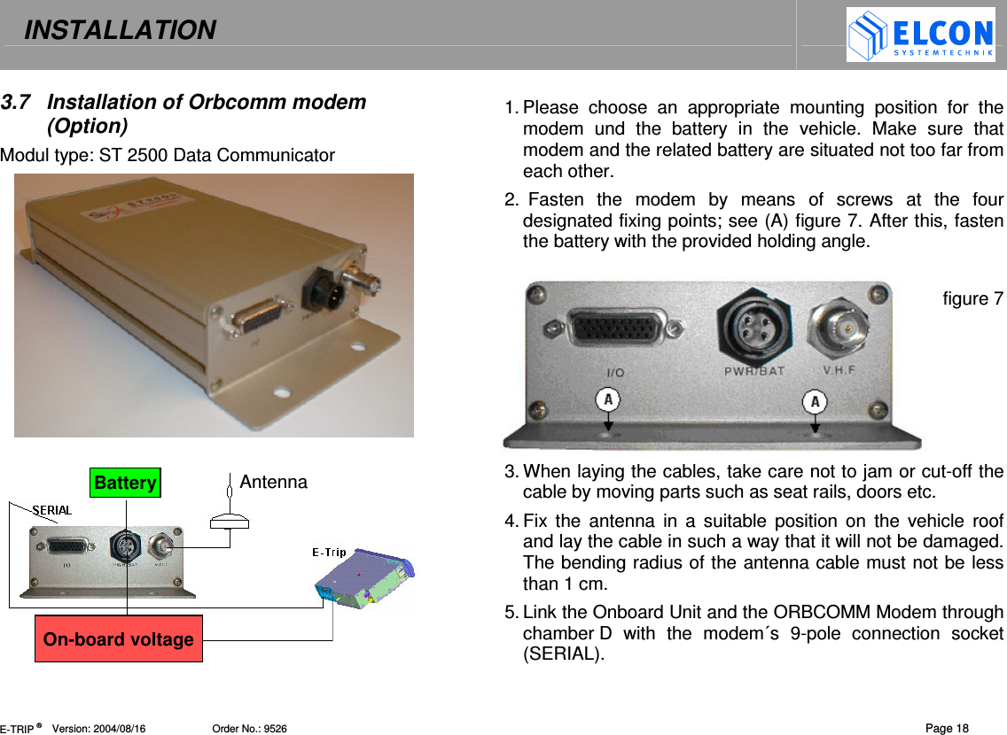
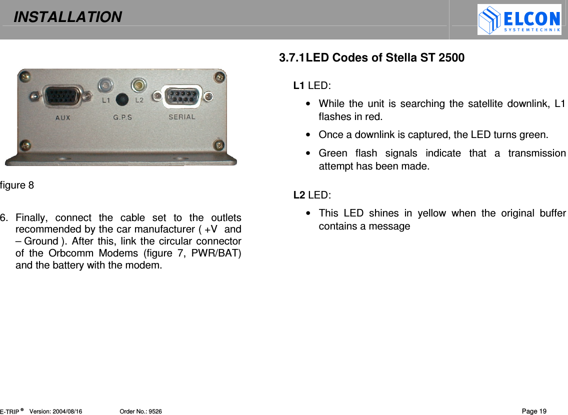
Mounting Manual
Navigation menu
Upload a User Manual
Namespaces
Wiki Guide
HTML
PDF
Info
Views
User Manual
Discussion / Help
Navigation