ELCON Systemtechnik 6618A EasyTrack 6618A User Manual UsersManual
ELCON Systemtechnik GmbH EasyTrack 6618A UsersManual
Contents
- 1. Manual
- 2. UsersManual
UsersManual

EasyTrack Version: 2004/06/17 Page 1
EasyTrack
ELCON BASIC SYSTEM FOR TRACKING DATA
Operating Manual
Order No.: 9537-1

IMPORTANT NOTES
EasyTrack Version: 2004/06/17 Page 2
NOTICE
This device contains 900 MHz/1800 MHz GSM functions that are not operational in U.S. Territories.
This filing is only applicable for 1900 MHz PCS operations.
Statement according to FCC part 15.19:
This device complies with Part 15 of the FCC Rules. Operation is subject to the following two conditions: (1) this
device may not cause harmful interference, and (2) this device must accept any interference received, including
interference that may cause undesired operation.
Statement according to FCC part 15.21:
Modifications not expressly approved by this company could void the user's authority to operate the equipment.
Statement according to FCC part 15.105:
NOTE: This equipment has been tested and found to comply with the limits for a Class B digital device, pursuant to
Part 15 of the FCC Rules. These limits are designed to provide reasonable protection against harmful interference
in a residential installation. This equipment generates, uses and can radiate radio frequency energy and, if not installed
and used in accordance with the instructions, may cause harmful interference to radio communications.
However, there is no guarantee that interference will not occur in a particular installation. If this equipment does cause
harmful interference to radio or television reception, which can be determined by turning the equipment off and on, the
user is encouraged to try to correct the interference by one or more of the following measures:
. Reorient or relocate the receiving antenna.
. Increase the separation between the equipment and receiver.
. Connect the equipment into an outlet on a circuit different from that to which the receiver is connected.
. Consult the dealer or an experienced radio/TV technician for help.
RF Exposure mobile:
The external antennas used for this mobile transmitter must provide a separation distance of at least 20 cm
from all persons and must not be co-located or operating in conjunction with any other antenna or transmitter.

IMPORTANT NOTES
EasyTrack Version: 2004/06/17 Page 3
Dear customer:
ELCON Systemtechnik would like to thank you for your confidence when purchasing the onboard unit EasyTrack.
This User Manual is intended to help you to activate your EasyTrack and the EasyTrack Manager as quickly as possible.
It provides you with a brief description of setup under Windows® operation systems.
Please make sure to read this user manual carefully, before you bring the unit into service!
Familiarize with the operation and functions of EasyTrack.
Keep the user manual and other descriptive documentation for your reference.
Should you still have questions as this manual might not cover all details, our service partner will be happy to help you.
This user manual is subject to change without notice.
Windows®, Windows NT® and Microsoft® are registered trademarks of Microsoft Corp.

SAFETY INSTRUCTIONS
EasyTrack Version: 2004/06/17 Page 4
Safety Notes
Before installing and starting the device, read the
information given in the operating manual most carefully.
In doing so, you will take advantage of the device’s full
scope of functions and avoid damages due to improper
use.
• The device reflects the current state of the art and
complies with the applicable safety standards.
• Operate the device only in proper condition and strictly
according to the operating instructions.
• Works on the device, including its opening, must only
be done by authorized service personnel.
• For the electrical connection of the device, ensure the
correct line voltage (see chapter Technical Data)!
• Always disconnect the device from mains before you
open it!
• In the event of failure, please contact the manufacturer
or your agency in charge.
• Only end devices complying with the safety standard
according to EN 60950 and bearing the CE-mark, are
permitted to be connected to the interfaces of the
device.
• The end devices must have suitable plug connections,
otherwise appropriate adapters are to be used.
• End devices must only be operated at the interfaces
provided for.
Besides the safety notes mentioned above, you will find
complementary installation instructions in the according
chapters.
This operating manual is subject to change without notice.
For any further questions relating to the
configuration and installation of your device,
please refer to the manufacturer.

TABLE CONTENTS
EasyTrack Version: 2004/06/17 Page 5
1 Introduction ............................................6
1.1 Practical application of EasyTrack................6
1.2 Symbols used in this manual.......................6
1.3 System requirements for installation.............7
2 Installation..............................................7
2.1 Scope of supply ........................................8
2.1.1 Vehicle equipment.....................................8
2.1.2 Office equipment.......................................8
2.1.3 Optional Accessories .................................9
2.2 Insertion of SIM card..................................9
2.3 Installation position and fastening .............. 10
2.4 Connection options.................................. 10
2.5 Installation of the device........................... 11
2.6 Installation instructions ............................. 12
2.7 Serial Interface (RS232)........................... 13
3 Relevance of the LEDs........................... 14
4 EasyTrack Manager ............................... 15
4.1 General Information................................. 15
4.2 Summary of functionalities........................ 15
4.3 System Requirements.............................. 15
4.4 First Steps ............................................. 16
4.5 Installation / Deinstallation ........................ 17
4.6 Uninstall EasyTrack Manager.................... 18
4.7 Working with EasyTrack Manager.............. 19
4.7.1 Starting EasyTrack Manager..................... 19
4.7.2 Presentation of EasyTrack Manager........... 19
4.7.3 Register Card “Settings”........................... 21
4.7.4 Register Card “Configuration” ....................26
4.7.5 Register Card “Actual Data” ......................31
4.7.6 Register Card “SMS Data” ........................33
4.7.7 Register Card “Office Modem (GSM)” .........34
4.7.8 Register Card “Firmware Upload”...............37
4.7.9 Register Card “Info“ .................................37
5 Changed Functionality on Different Firmware
Releases ...............................................38
6 Technical Data....................................... 39
6.1 Technical Description...............................39
6.2 Technical Data........................................40
7 Abbreviations ........................................42

INSTRUCTION
EasyTrack Version: 2004/06/17 Page 6
1 Introduction
1.1 Practical application of EasyTrack
EasyTrack is a most efficient positioning system
which is able to perform the parallel processing of up
to 12 GPS satellite signals and to send data relating
to the vehicle and its position to a central
office/transport company via GSM radio network. The
mobile device is part of a modern information and
monitoring system consisting of both hard and
software components serving for:
• innovative transport companies
• their partners
• and customers
The use of EasyTrack enables suppliers, transport
companies and customers to get essential
information about the vehicles in service as well as
their cargo and position via on-line access.
1.2 Symbols used in this manual
Warning
contains important information on operation of your
EasyTrack and EasyTrack Manager.
Caution
must be observed to avoid any problems on your
PC or damage of your EasyTrack.
Notes contain information on operation of your
EasyTrack and EasyTrack Manager.

INSTALLATION
EasyTrack Version: 2004/06/17 Page 7
1.3 System requirements for installation
The on-board voltage is permitted for 9 … 36V.
You can choose one of three different ways to
connect the EasyTrack to your vehicles power
cables:
1) If you connect the power pins and "Dig. Input 1"
to constant power, the EasyTrack will send
always SMS using the predefined interval
setting.
2) If you connect the power pins and "Dig. Input1"
to Ignition, the EasyTrack will send interval
SMS only if Ignition is ON. With every power
ON you will have no GPS data in the SMS until
GPS position is fixed.
3) If you connect the power pins to constant
power and "Dig. Input 1" to Ignition, the
EasyTrack will send interval SMS only while
Ignition is ON.
The GPS module is powered continuously, thus
a GPS position can be sent with every SMS
(depends on GPS availability) Note: The
EasyTrack will always draw about 100mA from
your vehicles battery!
The GPS antenna must be installed in such a way that its
free line to the sky is ensured.
The GSM antenna must be installed in such a way that a
free connection to the GSM net can be established and
its shielding by metal parts is excluded.
2 Installation
Before you start the installation of the device make sure to
follow the best sequence for you to work on.
For a normal setup we recommend this sequence:
1) Operate the EasyTrack first close to your PC using the
optional power supply for EasyTrack.
2) Configure the EasyTrack with your specific data
(EasyTrack-ID, PIN, vehicle sensor information,
interval time,…). See chapter 4.7.3
3) Install the EasyTrack inside the vehicle and test it. See
chapter 2.5
If you own a laptop which is capable of running the
EasyTrack-Manager, we recommend you to install the
EasyTrack inside the vehicle and make the configuration and
test on board.
INSTALLATION
EasyTrack Version: 2004/06/17 Page 8
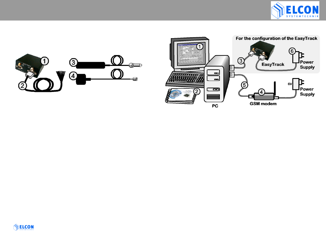
2.1 Scope of supply
2.1.1 Vehicle equipment
1. EasyTrack device
Order no. 6618
2. Cable loom power / input
Order no. 9409
3. GSM antenna
Order no. a0397
4. GPS antenna
Order no. 9410
2.1.2 Office equipment
1. PC software EasyTrack Manager
for Microsoft Windows® Order no. 9542
2. EasyTrack Operating Manual
Order no. 9537
3. Null modem cable 3m
Order no. 9541
4. GSM/GPRS Office Modem (Triband)
Order no. 9372
5. Connecting cable for office modem 1.8m
D-Sub connector, male/female, 9 pin.
Order no. 9512
6. Power Supply for EasyTrack
Order no. a0075
INSTALLATION
EasyTrack Version: 2004/06/17 Page 9
2.1.3 Optional Accessories
If your PC has no serial interface (RS232), but a USB
interface, you may realize the connection to
EasyTrack also via a USB converter.
• USB converter
including serial cable, adapter and driver CD
Order no. 9520
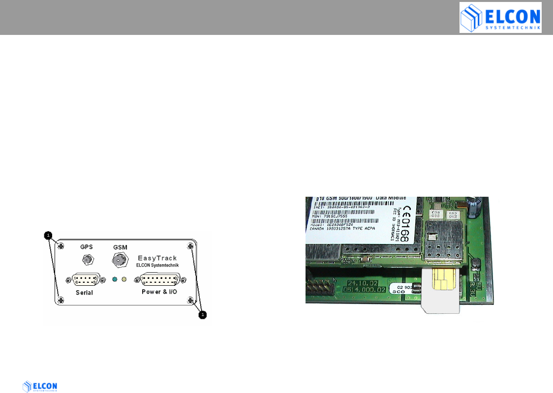
2.2 Insertion of SIM card
Use a normal 3V or 5V SIM card for mobile phones
Before installing EasyTrack, the SIM card must be
inserted into the device. For this purpose, open the 4
screws at the front side of the device.
Pull the circuit board out of its enclosure. Afterwards insert
the SIM card you received from the service supplier with its
beveled edge at the correct position into the device (see fig.
1). If you have received a check card format SIM card,
please remove the smaller section.
In order to avoid any destruction of EasyTrack, the
device must be switched off!
To reduce the risk of damaged equipment. Before any
part of the circuit board is touched be sure to discharge
yourself by touching a grounded surface of the device!
figure 1; insert SIM card
INSTALLATION
EasyTrack Version: 2004/06/17 Page 10
2.3 Installation position and fastening
The device is contained in a small box, which may be
attached to a surface using 4 screws at the fastening
points.
The device has neither a keyboard nor a display and
can therefore be installed in a concealed position.
As to the installation of EasyTrack, any installation
position is allowed, as long as you choose a dry
place where no person can be injured.
Be sure the cables are tied closely to the easy track
to prevent excessive vibrating of the cables, and
possible damage to the connectors.
Do not install the cables in such a way that they are
tight or strained, allow some slack to avoid potential
cable damage
Windows®, Windows NT® and Microsoft® are registered trademarks of
Microsoft Corp.
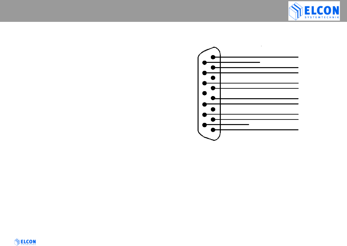
2.4 Connection options
Digital Inputs (9…36V):
Connect the positive line to (a) and the ground to (b)
Signals with the same name are already connected inside
the EasyTrack.
purple
POWER & I/O
Supply + (9...36V)
Supply + (9...36V)
Dig. In 1 (a)
Dig. In 1 (b)
Dig. In 2 (a)
Dig. In 2 (b)
Dig. In 3 (a)
Dig. In 3 (b)
V-PULSE Input
RPM-PULSE Input
Supply GND
Supply GND
view to the solder
side of the
cable connector
red
black
orange
blue
yellow
grey
green
pink
brown
1
9
2
10
3
11
4
12
5
13
6
14
7
15
8

INSTALLATION
EasyTrack Version: 2004/06/17 Page 11
2.5 Installation of the device
Safety notes:
Upon the installation of EasyTrack, the
following safety notes must be observed!
• When disconnecting the negative pole of the battery, the
safety instructions of the automobile manufacturer must
be observed.
• When drilling holes for the fixing of EasyTrack, it must be
paid attention to the fact that neither parts of the vehicle
nor electric cables are damaged.
• The cross section of the positive and negative cable must
be no less than 0.5 mm2.
• In the event of faulty installation, operational malfunctions
of the vehicle’s electronic system or of the EasyTrack may
occur.
• The manufacturer’s supplied cables must be used when
connecting EasyTrack to the connection points
recommended by the vehicle manufacturer.
• For safety reasons we recommend that you install the
GSM antenna at least one meter away from any persons
in the driver's cabin
INSTALLATION
EasyTrack Version: 2004/06/17 Page 12
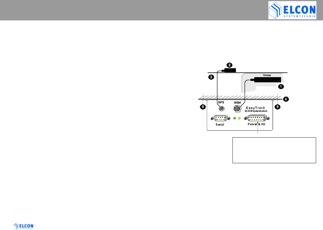
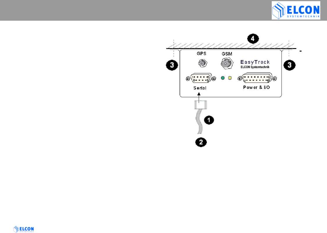
2.6 Installation instructions
See figure 2; wiring overview
• Select any installation position in the vehicle.
• Bore the fastening holes for the fastening angles.
Observe the above mentioned safety
instructions!
• Fix the EasyTrack at the vehicle.
• Establish the cable connection between
EasyTrack and vehicle.
To avoid short circuits, make sure that the
cables neither jammed nor cut off by flexible
vehicle parts!
• Selection of a suitable position for the GPS and
GSM antennas.
Undisturbed satellite communication must be
ensured!
• Bore the fastening holes and establish the cable
grommet for the GPS and GSM antennas.
Observe the above mentioned safety
instructions!
The GSM antenna is an stick-on-window mount style
antenna.
• Establish the cable connection between the EasyTrack
and the GPS and GSM antennas.
Bend radius must be minimum 1cm!
figure 2; wiring overview
GSM antenna
GPS antenna
Car roof
Car chassis
Fastener for the fixing
• Power input of EasyTrack
• Input of v pulse and RPM pulse
• 3 digital input
•
wiring cable ( )
INSTALLATION
EasyTrack Version: 2004/06/17 Page 13
2.7 Serial Interface (RS232)
• Via the serial interface RS232 it is possible to
connect a PC or notebook to configure EasyTrack.
• The end devices must have compatible plug
connectors. Their connection must be realized
only by means of the transmission cable
recommended by the manufacturer.
• It might be necessary to use suitable adapters.
• The end devices must only be connected to the
interface provided for.
Serial interface cable (null modem cable)
Service/configuration
(possible connections: PC, Notebook)
Fastener for the fixing
Car body

FUNCTION OF LEDS
EasyTrack Version: 2004/06/17 Page 14
3 Relevance of the LEDs
At the front side of the device, a green and a yellow
LED indicate the operational status of EasyTrack.
Immediately after switching on the EasyTrack, its
boot loader is started which allows the upload of new
EasyTrack firmware. During this time (approx. 2
seconds) both LEDs flash rapidly. After that the
yellow LED indicates that the hardware check is
carried out. Following the hardware check, the yellow
LED is turned off and the green LED flashes slowly.
In this case the device is ready to operate - but it is
still waiting for a valid GPS-position. The green LED
will stay on permanently once the GPS position
connection has been established.
The yellow LED indicates the state of Dig. Input 1. If
you have connected the EasyTrack to permanent
power and your vehicles ignition is connected to Dig.
Input 1, the Yellow LED will be permanently on when
activated by the ignition. (SMS transfer enabled) and
turn off while ignition is off (SMS disabled).
Additionally there is an internal activity of the GSM-Modem
displayed by flashing on the yellow LED.
The duration of the flashing helps you to determine the
actual operation of the GSM-Modem:
short (approx. 0,5s): EasyTrack checks incoming SMS.
medium (approx. 2..4s): Sending SMS
long (> 6s) : SMS cannot be sent
Since firmware version 2.3 the yellow LED flashes slowly
when the GSM filed intensity is below 10%, so this is an
indicator (like the green LED for GPS), that no net is
available to send an SMS.
If the yellow LED flashes very quick with the following
pattern: 3 time on, then pause (and so on), then a GSM error
exists. Either no SIM card or the wrong PIN are entered.
Connect a laptop to the EasyTracks serial port to see the
details.

EASYTRACK MANAGER
EasyTrack Version: 2004/06/17 Page 15
4 EasyTrack Manager
4.1 General Information
EasyTrack Manager is a software program, which
works on a standard PC, equipped with Windows 9x /
NT 4.0 / Windows 2000 or Windows XP. To run this
program, no special hardware is required. The
program name of the EasyTrack Manager is:
EasyTrackManager.EXE. The program
EasyTrack Manager consists of 2 files: the
executable file EasyTrackManager.EXE and the
initialisation file EasyTrackManager.INI.
4.2 Summary of functionalities
• Writing configuration data into the EasyTrack,
• Reading configuration data from the EasyTrack
• Receiving SMS data from EasyTrack via GSM
office modem
• Sending SMS data via GSM office modem
• Logging data from EasyTrack within a tracking
file for displaying the coordinates within a map
• Logging data from EasyTrack and other
sources of informations within a LOG file
4.3 System Requirements
Hardware:
PC-compatible computer with:
• Intel® Pentium® Processor or compatible with 266 MHz
or higher
• 32 MB RAM
• 5 MB of disk space
• 640 x 480 minimum screen resolution
• minimum one serial port
Software:
The EasyTrack Manager is a 32-bit application. It runs on
Microsoft®
• Windows 95 / 98 / 98 SE
• Windows NT 4.0
• Windows 2000
• Windows XP
Intel® and Pentium® are registered trademarks of Intel Corp.
Windows®, Windows NT® and Microsoft® are registered trademarks of Microsoft Corp.
EASYTRACK MANAGER
EasyTrack Version: 2004/06/17 Page 16
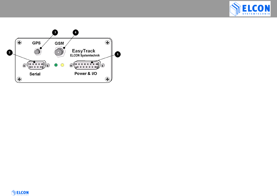
4.4 First Steps
figure 3; front view
• Make sure that your PC and the EasyTrack are
switched off.
• Connect your EasyTrack to the main power supply
connector and have a look on the LEDs to
check the proper operation of EasyTrack. Directly
after power-up, both LEDs flash quickly for the
period of 5 seconds. Afterwards, the green LED
indicates the hardware status, while the yellow
LED indicates the communication status with the
GSM modem. The green LED flashes slowly
(1 s on/1 s off) if everything is in order.
• Plug one end of the null modem cable supplied into the
appropriate port of the EasyTrack and the other end
into a free serial port (e.g. COM1 or COM2) on your PC.
• Plug the antenna connector for GPS into port .
• Plug the antenna connector for GSM into port .
• Switch the computer on and follow the instructions of the
chapter: Installation
EASYTRACK MANAGER
EasyTrack Version: 2004/06/17 Page 17
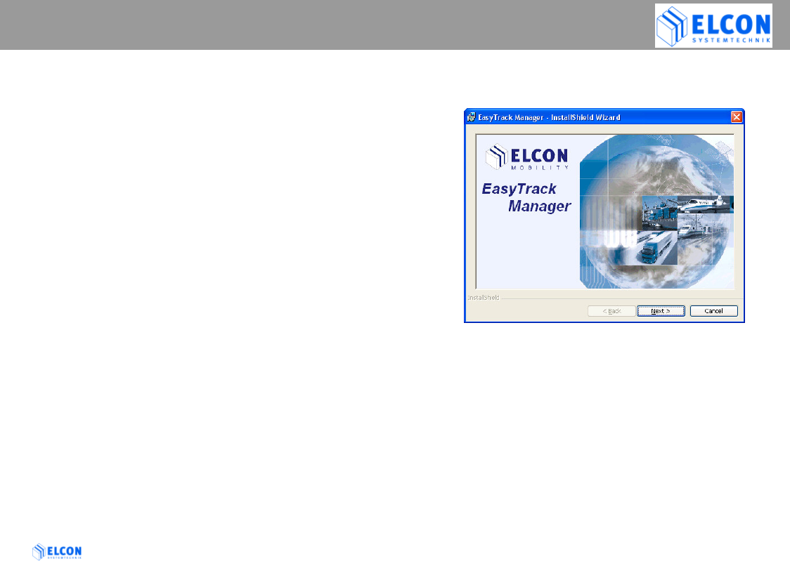
4.5 Installation / Deinstallation
To install EasyTrack Manager on your computer
1) Start Windows®
2) Insert the EasyTrack Manager CD into the CD-ROM
drive, and then follow the directions on the screen.
If the installation program does not start
automatically, click on Start and then on Run. In the
Run dialog box, enter E:\SETUP.EXE in the
command line and click on the OK button. If your
CD-ROM drive has a drive letter other than E,
substitute the appropriate letter.
The installation program starts. The subsequent
procedure is menu-driven. The remainder of the
installation is automatic, so that it is not required to
enter any further information.
figure 4; Splash Screen
3) Select the preferred options and follow the on-screen
instructions.
4) After the EasyTrack Manager software has been
successfully installed, click on the button Finish to
exit the installation program.
EASYTRACK MANAGER
EasyTrack Version: 2004/06/17 Page 18
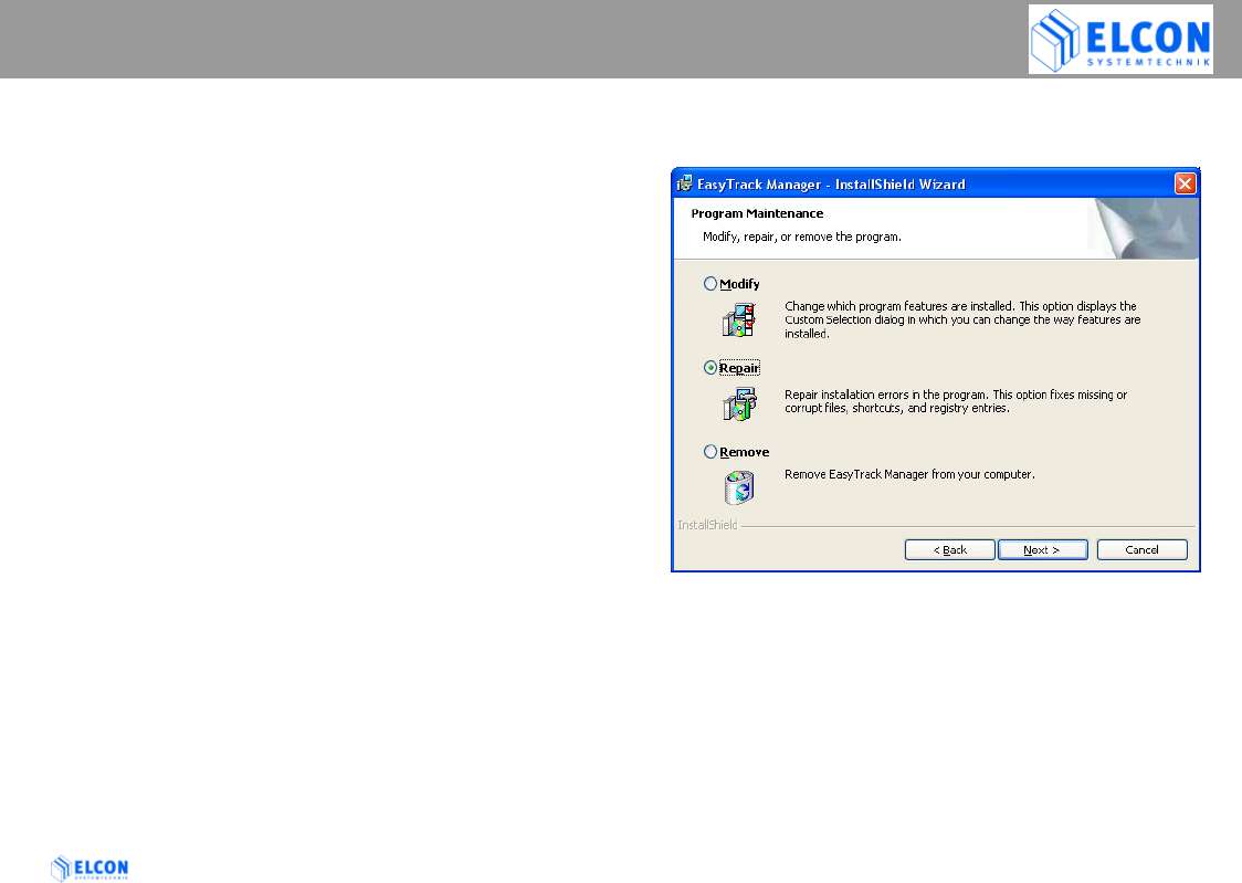
4.6 Uninstall EasyTrack Manager
To uninstall EasyTrack Manager on your computer, click
on
Start Program Files ELCON mobility
EasyTrack Manager Uninstall EasyTrack Manager
or start the SETUP.EXE of EasyTrack Manager from the
CD-ROM and follow the on-screen instructions.
Note:
If the EasyTrack Manager does not start or run properly,
try to repair your installation by calling the SETUP.EXE of
EasyTrack Manager from the CD-ROM. Select the Repair
button in the following dialog. This option fixes missing or
corrupt files, shortcuts, and registry entries.
If you need to update or repair the EasyTrack Manager all
CSV files (for Mappoint) and also the LOG file will remain
on your computer. So no data will get lost.
figure 5; repair installation
EASYTRACK MANAGER
EasyTrack Version: 2004/06/17 Page 19
4.7 Working with EasyTrack Manager
4.7.1 Starting EasyTrack Manager
Click one after the other on the following buttons on your
task bar:
Start Program Files ELCON mobility
EasyTrack Manager EasyTrack Manager,
to start the program, or do a double click on the
EasyTrack Manger symbol in the new program group.
Click on Start and then in succession
Program Files ELCON mobility
EasyTrack Manager EasyTrack Manager
to start the program or do a double click onto the
EasyTrack Manager symbol which is displayed on the
desktop screen.
4.7.2 Presentation of EasyTrack Manager
The application has been developed for a monitor
resolution of at least 640*480 pixels. After the program
start, a start-up sequence is displayed for approx. 5 sec.
After that, the main window is opened with a number of
individual work packages implemented on register cards.
For the EasyTrack configuration as well as for the
configuration of the application, the following register
cards are available:
• Configuration
• Actual Data
• SMS Data
• Office Modem (GSM)
• Settings
• Firmware Upload and
• Info.
figure 6; main window

EASYTRACK MANAGER
EasyTrack Version: 2004/06/17 Page 20
4.7.2.1 Start-Up Sequence
For the start-up sequence, the EasyTrack Manager shows
the following message box for 5 seconds. The displaying
of the start-up window can be terminated by pressing the
left mouse key within the displaying window. As an
alternative, the ESC key can be used. After the start-up
sequence, the last used register card is shown.
figure 7; start-up screen
EASYTRACK MANAGER
EasyTrack Version: 2004/06/17 Page 21
4.7.2.2 Status Bar
The status bar is displayed in the lowest line of the
application window. On the right side of the status bar you
can see the status of the communication to an EasyTrack.
The following states are considered:
EasyTrack COM not open The COM port indicated on
the register card Settings is
not open.
EasyTrack not available The interface indicated could
be opened, however, it
cannot communicate with an
EasyTrack.
EasyTrack available Communication with an
EasyTrack exists.
4.7.2.3 Use of the keyboard
Via the TAB key the name of a register card can be
selected. If one card has shown the input focus as
displayed in figure 6, another register tab can be selected
via the right or left cursor keys. The controls on one
register card can be chosen by the TAB key.
If the input focus is on a combo box, the list box of this
combo box is about to be made visible with the key F4.
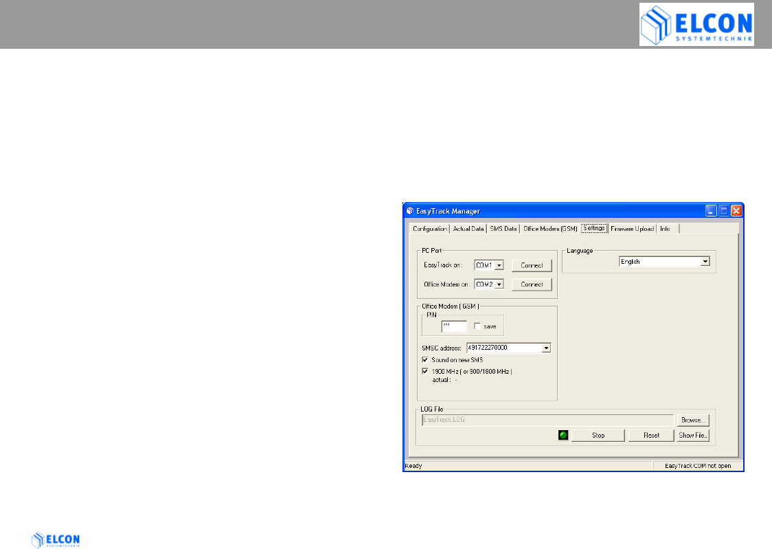
4.7.3 Register Card “Settings”
figure 8; Register Card Settings
EASYTRACK MANAGER
EasyTrack Version: 2004/06/17 Page 22
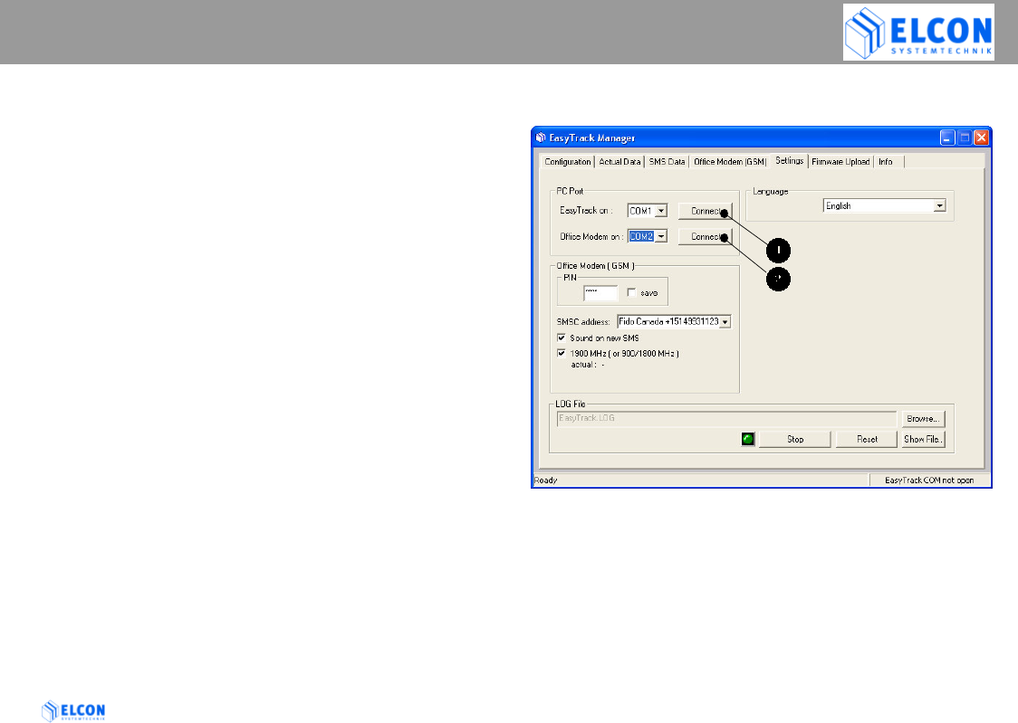
4.7.3.1 PC Port
After the first start of the EasyTrack Manager, the
application is not connected automatically to a COM
port. The user has to define, which COM port shall be
used by the application. After the definition of the COM
port, press the appropriate Connect button to connect
the COM port to the EasyTrack (see ) or the GSM
office modem (see ). If a connection has been
established, the appropriate button text is switched to
Disconnect. All COM ports are closed automatically if
the application is closed.
4.7.3.2 Language
In the field Language one of two national languages
(English and German) can be chosen to be used by the
application for the text display and file entries.
4.7.3.3 Office Modem (GSM)
The GSM modem is a GSM900/1800/1900 Phase II+
device. 1900MHz band is used in North America; see
checkbox 1900MHz.
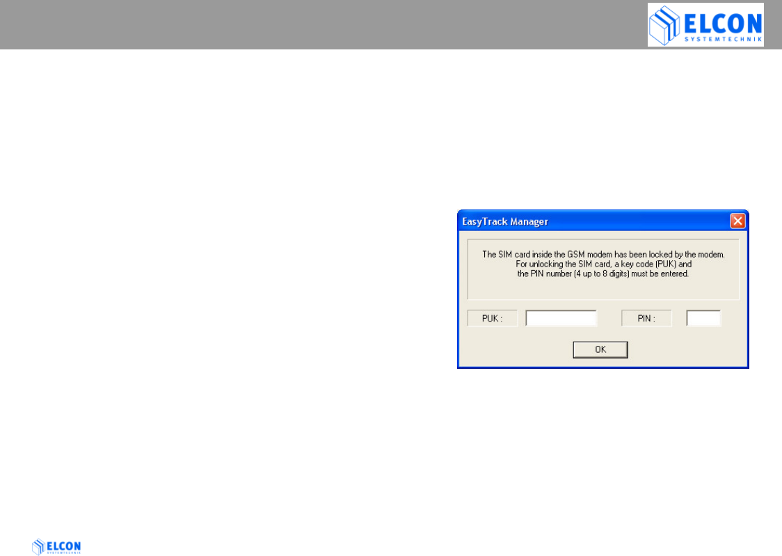
PIN
Depending on the type of your SIM card, it may be
protected against misuse by a four- to eight-digit PIN.
If required, enter the according PIN, which is stored
on the SIM card, into the input field. If no pin is
required, select the checkbox automatic
If the wrong PIN is transmitted to the office
modem three times, the SIM card will be
blocked. At the same time, the
EasyTrack Manger opens a dialog box for the
entry of the PUK and PIN.
figure 9; PUK dialog
save
If the check box (displaying options) is activated, the
PIN in the edit field will be saved into the INI file.
SMSC address:
Please enter the phone number of the service center
in the manner described by the network operator.
Enter the SMSC address with the international
access character +

EASYTRACK MANAGER
EasyTrack Version: 2004/06/17 Page 23
The SMSC is necessary to send a SMS from the
office modem to the EasyTrack.
Sound on new SMS
If this checkbox is activated, a signal is emitted via
the loudspeakers in the event of an incoming SMS.
1900 MHz (or 900/1800MHz)
Activate this checkbox if your GSM modem should
work in 1900 MHz band (i.e. North America).
If the actual band setting is not the required one, do
the following steps to change the band setting.
1) disconnect COM port
2) activate or deactivate the checkbox 1900MHz
3) connect COM port
4) now modem waits for a power cycle. Reconnect the
power supply of the office modem to apply the
change.
5) reconnect COM port
EASYTRACK MANAGER
EasyTrack Version: 2004/06/17 Page 24
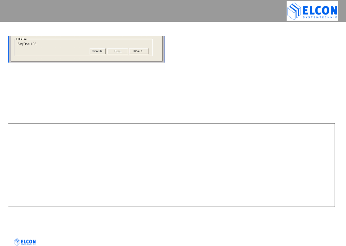
4.7.3.4 LOG File
figure 10; LOG file
The EasyTrack-Manager writes a lot of useful information
into the specified file as plain text.
You can change the filename and folder within the dialog
box that appears when you click Browse (button)
Example of a LOG file
=========================================================================
C:\Program Files\ELCON mobility\EasyTrack Manager\EasyTrack.LOG
========== START EasyTrack Trace 12:35:19 PM Monday, December 16, 2002 ==========
12:35:20 PM 12/16/2002: EasyTack Manager: Software Version: 1.20
12:35:20 PM 12/16/2002: GSM Office Modem: Type: Motorola
12:35:20 PM 12/16/2002: GSM Office Modem: Software Version: g18_vE6.02.10.00
12:35:20 PM 12/16/2002: GSM Office Modem: Actual Band Setting: 1900 MHz
12:35:21 PM 12/16/2002: GSM Office Modem: actual SMSC: +15149912345
12:35:21 PM 12/16/2002: GSM Office Modem: Signal Quality: 100 %
12:35:32 PM 12/16/2002: M1;EasyTrack ;OK;OK;165136161202;A;N;4255.8952;W;08113.2900; 1; 1; 0; 0; 1; 0; 0;I; 0;I; 0;I;
0; 0000; 0; 0; 0; 0; 0;*06

EASYTRACK MANAGER
EasyTrack Version: 2004/06/17 Page 25
Browse (button)
Via the Browse...button, any file with suffix .LOG
can be selected from any folder.
If the filename entered doesn't exist, a new file
will be generated.
Show file (button)
In order to show the content of the file indicated
in the input field, the button Show file can be
selected. This button is only active if the file
indicated in the input field also physically exists.
The log file is an ASCII file, which is displayed
with NOTEPAD.EXE or WORDPAD.EXE.
Note:
NOTEPAD.EXE is only able to handle a file size
of less than 64 kBytes.
Reset (button)
After the selection of the button Reset, the
content of the LOG file will be deleted.
EASYTRACK MANAGER
EasyTrack Version: 2004/06/17 Page 26
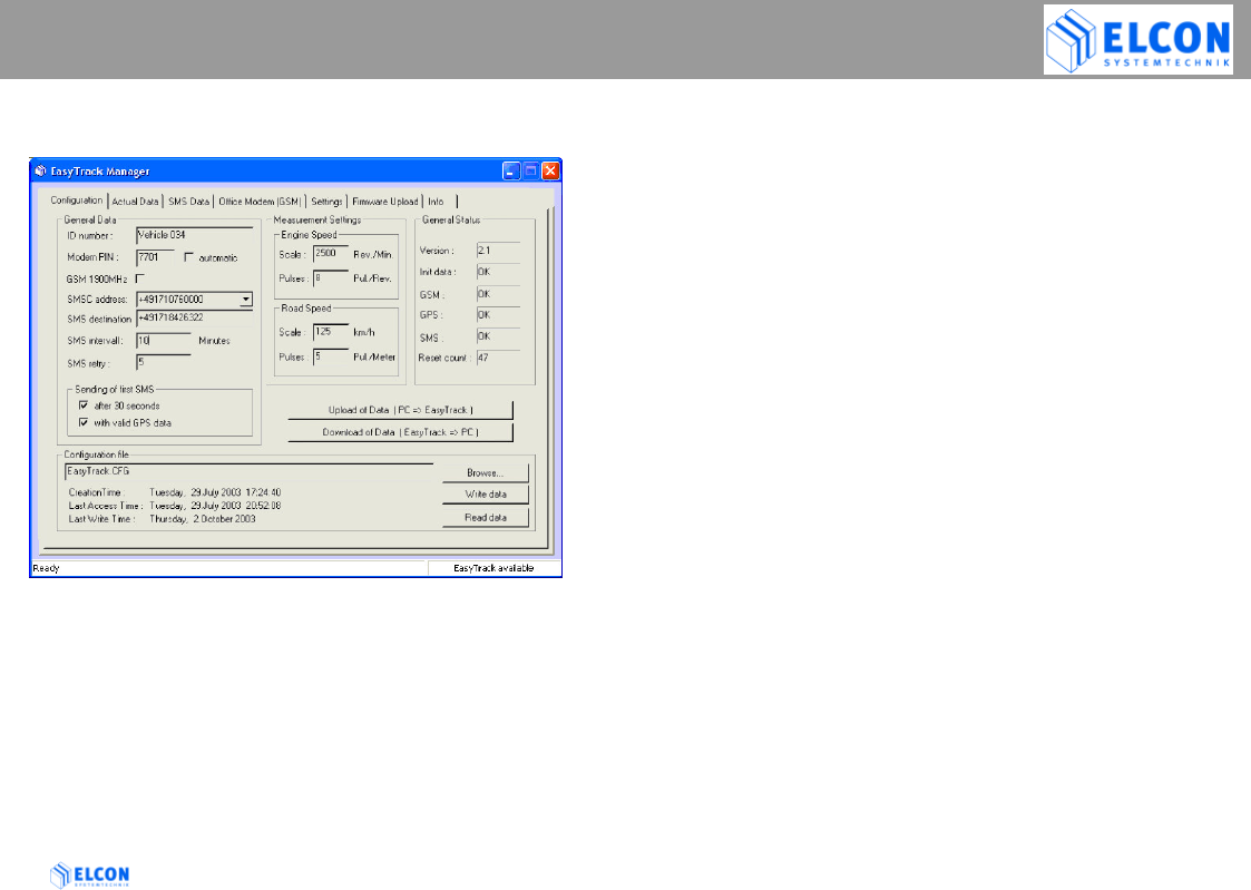
4.7.4 Register Card “Configuration”
figure 11; Register Card Configuration
Note:
This register card will only show data, if you have a
enabled connection to your EasyTrack.
Via the register card Configuration, the configuration
data of EasyTrack are entered. In order to realize a
minimum configuration of EasyTrack, the fields have to
be specified within the group General Data. However, this
way EasyTrack can only perform the transmission of the
position but not of the vehicle-related data such as road
speed, driving time, engine speed, idle time and distance.
To carry out a configuration of EasyTrack, a direct connection
between PC and EasyTrack via a serial cable must exist
(please refer to chapter “Status Bar”).
• Status Bar
In the lower right corner of the application, the
EasyTrack Manager communication status to EasyTrack is
displayed. If EasyTrack COM not open is displayed, no
upload or download of data is possible. In addition, no
actual data can be read from EasyTrack. Refer to PC Port
on register card Settings, to open the appropriate COM
port. If COM port is open and EasyTrack is connected with
the EasyTrack Manager, EasyTrack available is shown in
the status bar. If the EasyTrack Manager cannot
communicate with EasyTrack, EasyTrack not available is
displayed.
On the left hand side of the status bar, communication
errors between EasyTrack and EasyTrack Manager and
other sources of information are displayed.

EASYTRACK MANAGER
EasyTrack Version: 2004/06/17 Page 27
• General Data
The fields within the group General Data must be
indicated to ensure the faultless functioning of
EasyTrack.
ID number
In the field ID number a name with 15 characters
at most must be specified, through which you
may identify the corresponding device if
EasyTrack sends an SMS to the office modem.
Modem PIN
Depending on the type of your SIM card, it may
be protected against misuse by a four-digit PIN.
If required, enter the according PIN, which is
stored on the SIM card, into the input field. If no
pin is required, select the checkbox automatic.
If the wrong PIN is transmitted to the GSM
modem three times, the SIM card will be
blocked. In this case, extract the SIM card
from the EasyTrack and insert it into a GSM
mobile phone. Via the mobile phone, the
PUK and PIN, which are now required, can
be entered.
automatic ( Checkbox )
see Modem PIN
GSM 1900 MHz ( checkbox )
The default setting of the GSM modem is for
900/1800MHz band. For PCS operation (1900MHz) you
need to change the band.
Do the following steps to change the band settings:
1) activate the checkbox 1900MHz
2) use the button Upload of Data to apply the data
to EasyTrack and GSM modem
3) follow the instructions of EasyTrack Manager,
then remove the power supply of the EasyTrack
for about 5 seconds to apply the change
4) reconnected the EasyTrack and wait for it to be
responding again to the EasyTrack Manger.
SMSC address
enter the phone number of the service center (SMSC =>
Short Message Service Center) in the manner as
described by the network operator. Enter the SMSC
address with the international access character + (e.g.
+15149931123 ).
SMS destination
Please enter the phone number to which EasyTrack
shall send the messages. Enter the phone number with
the international access character + .

EASYTRACK MANAGER
EasyTrack Version: 2004/06/17 Page 28
SMS interval
Please specify the period of time for which
EasyTrack shall wait between two messages.
The maximum value is 1440 minutes, which is
equal to 24 hours.
SMS retry
Please enter the number of retries (1 up to 10)
which EasyTrack shall carry out in the event of a
GSM communication error - for instance if
EasyTrack temporarily cannot find any GSM net.
The default value of EasyTrack is 5 retries.
Sending of first SMS
after 30 seconds ( Checkbox )
Select the checkbox for sending an SMS after 30
seconds after power-up of EasyTrack.
Sending of first SMS
with valid GPS data (Checkbox )
Select the checkbox for sending an SMS after
power-up, if EasyTrack has a valid GPS position.
• Measurement Settings
If EasyTrack is supposed to transmit also the vehicle-
related data within a SMS, the scaling parameters for
Engine Speed and/or Road Speed must be specified.
Since the number of impulses per kilometer varies with
different vehicles, it is necessary to adjust EasyTrack
for the appropriate vehicle.
Note: In all fields only decimal numbers are allowed.
Engine Speed Scale (Rev./Min.)
In the input field, enter the 100% value, which is to be
used by EasyTrack as a maximum value when
partitioning into 3 ranges (Range 1 up to Range 3) see
chapter 4.7.5 Range 1, 2 and 3.
This input field has a maximum value of 65535
revolution per minutes.
Engine Speed Pulses (Pul./Rev.)
The numerical characteristic giving the value of the
input signal required to show and record the revolutions
of the engine. This constant shall be expressed in
pulses per revolution. This input field has a maximum
value of 255 pulses per revolution.
Road Speed Scale (km/h)
see: Engine Speed Scale
This input field has a maximum value of 65535
kilometers per hours.
Note: 1 km/h <=> 0.621 mph
Road Speed Pulses (Pul./Meter)
The numerical characteristic giving the value of the
input signal required to show and record a distance
traveled of one meter. This constant shall be expressed
in pulses per meter. This input field has a maximum
value of 255 pulses per meter.
Note: Since Firmware Release 2.0: If you enter the value 0 (zero)
here, the EasyTrack will use the GPS speed instead of wheel
pulses

EASYTRACK MANAGER
EasyTrack Version: 2004/06/17 Page 29
• General Status
All data in this group will be updated every 5
seconds.
All shown values represent the sum of the bits that
are set.
Example: GSM Error "5" means that Bit 1 & Bit 4 are
set
Version
Shows the software version of the firmware of
EasyTrack.
Init data
The field Init data displays OK if, within the value
transmitted by EasyTrack, the following bits are
set:
Bit 1 target number OK
Bit 2 provider number OK
Bit 4 phone number of EasyTrack OK
Bit 8 PIN OK
Bit 16 parameter for speed and revolution
measurement ok
If one or several bits are not set, a configuration
error has occurred. In this case, check your
configuration data and reload the modified
configuration into the EasyTrack.
GSM
Shows the status for the GSM module of EasyTrack. If
no error has occurred, OK is displayed. EasyTrack
signalizes the following error statuses:
Bit 1: faulty AT command test
GSM module does not answer to an AT
command.
Bit 2: incorrect PIN
insert a PIN which is valid for the SIM card, into
the field Modem PIN. Reload the configuration
data into the EasyTrack.
Bit 4: error within the SMS provider number
enter a valid SMSC in the field SMSC address.
Reload the configuration data into the
EasyTrack.
Bit 8: SIM card error
Check whether the SIM card has been inserted
according to installation instructions (see chapter
2.2). If you cannot identify any fault, check the
SIM card by means of a mobile phone.

EASYTRACK MANAGER
EasyTrack Version: 2004/06/17 Page 30
GPS
Shows the status for the GPS module of EasyTrack.
If no error has occurred, OK is displayed. EasyTrack
signalizes the following error states:
Bit 1: no signal received from GPS receiver
Bit 2: no telegram received from GPS receiver
Bit 4: no response from GPS receiver
SMS
Shows the SMS status of EasyTrack. In the
current version of the EasyTrack firmware, no
error is signalized yet, for this reason the field
SMS of EasyTrack Manager displays OK.
Reset count
Shows the number of the resets carried out by
EasyTrack.
• Configuration file
On register card Configuration, all configuration data can
be entered through a dialog field. All input data are stored
after having left this register card and in case the program
is closed. In addition, the input data can be stored in a
configuration file (.CFG). For this purpose, a valid path and
file name have to be indicated in the input field
Configuration file. If no file name has been given yet, the
storing of a file can also be started through the button
Write data.... In this case it has the same function like the
button Browse... and the data will be written after file
selection. If the file indicated in the input field
Configuration file is found, the data of this file are shown
in the according fields (Creation Time, Last Access Time
and Last Write Time. The data can now be stored with the
Write data... button.
• Upload of Data ( PC => EasyTrack )
If a connection to EasyTrack is available, all entries on the
register card Configuration can be loaded into EasyTrack.
Please observe that EasyTrack must carry out a reset to
adopt the new data.
• Download of Data ( EasyTrack => PC)
If a connection to EasyTrack is available (see status bar),
actual data of EasyTrack will be downloaded after clicking
on this button. This function works also automatically, after
selection of register card Configuration.
EASYTRACK MANAGER
EasyTrack Version: 2004/06/17 Page 31
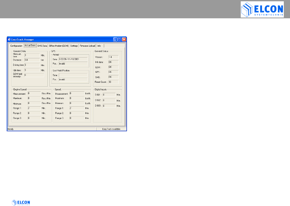
4.7.5 Register Card “Actual Data”
figure 12; Register Card Actual Data
On the register card Actual Data all currently valid
data of EasyTrack are displayed.
• General Data
Measure. time
Indicates the measurement period which has
passed since the transmission of the last SMS.
Distance
Indicates the distance which has been covered since
the transmission of the last SMS.
Driving time
Indicates the driving time (speed > 0 km/h) which has
passed since the transmission of the last SMS.
Idle time
Indicates periods of idle time (speed = 0 km/h)
occurred since the transmission of the last SMS.
GSM field intensity
Indicates the current radio field strength 0 – 100%.
• GPS
Actual Time
Displays the time/date received by the GPS receiver
not in UTC format, but as local time. The time zone as
set under windows and the settings for summer time
are considered.
Actual Pos.
Indicates the current position of EasyTrack.
Within the group Last Valid Position the last valid
position and time/date displayed under Actual are
shown.

EASYTRACK MANAGER
EasyTrack Version: 2004/06/17 Page 32
• General Status
The data within the group General Status are
displayed as described under Register Card
“Configuration”.
• Engine Speed
Measurement
Indicates the current value of the motor’s
rotational speed in revolution per minute.
Maximum
Indicates the maximum value in revolution per
minute performed since the last SMS
transmission.
Minimum
Indicates the minimum value in revolution per
minute performed since the last SMS
transmission.
Range 1
Indicates the motor’s rotational speed in
percent, within the scope of 0 and 30% of the
maximum revolution.
Range 2
Indicates the motor’s rotational speed in
percent, within the scope of 30.1 and 80% of
the maximum revolution.
Range 3
Indicates the motor’s rotational speed in
percent, within the scope of 80.1 and 100% of the
maximum revolution.
• Speed
Measurement
Indicates the current speed value.
Maximum
Indicates the maximum value in km/h performed since
the last SMS transmission.
Minimum
Indicates the minimum value in km/h performed since
the last SMS transmission.
Range 1
Indicates the speed in percent, within the scope of 0
and 30% of the maximum speed.
Range 2
Indicates the speed in percent, within the scope of 30.1
and 80% of the maximum speed.
Range 3
Indicates the speed in percent, within the scope of 80.1
and 100% of the maximum speed.
• Digital Inputs
Shows the status of the signal inputs DIGI1, DIGI2 and
DIGI3.
For further information, please refer to chapter 2.4.
EASYTRACK MANAGER
EasyTrack Version: 2004/06/17 Page 33
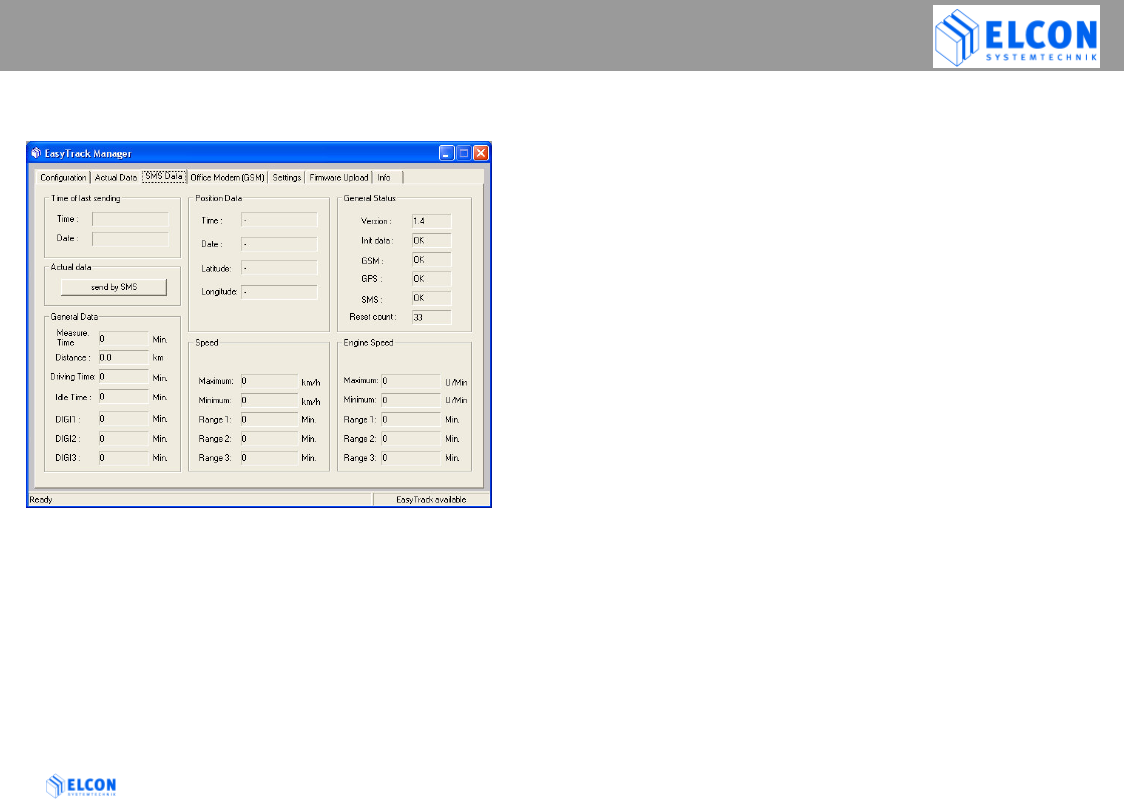
4.7.6 Register Card “SMS Data”
figure 13; Register Card SMS Data
On the register card SMS Data, the data of the SMS
last sent by EasyTrack are indicated. For this
purpose, a direct serial cable connection to the
EasyTrack is required. The relevance of the
according fields corresponds to those described in
chapter 4.7.5 Register Card “Actual Data”. All
differing fields are subsequently described.
•
• Time of last sending
Indicates time and date (local time) at which Easy Track
has sent the last SMS.
• Actual Data
If the EasyTrack is ready-to-receive, i.e., connected to the
EasyTrack Manager (see chapter 4.7.2.2), EasyTrack can
be requested to send the current data by clicking on the
button send by SMS. In the event of according
configuration, the receipt of these data can be stated on
the register card Office Modem (GSM).
• Position Data
Within the group Position Data the current data of the
position valid at the time, when the last SMS has been
sent by EasyTrack, are indicated.
Time
Date
Shows the time/date received by the GPS receiver not
in UTC format, but as local time. The time zone as set
under windows and the settings for summer time are
considered.
Latitude
Longitude
Indicates the current position. If the GPS receiver
cannot determine any position or no valid position yet,
“invalid” is displayed.
EASYTRACK MANAGER
EasyTrack Version: 2004/06/17 Page 34
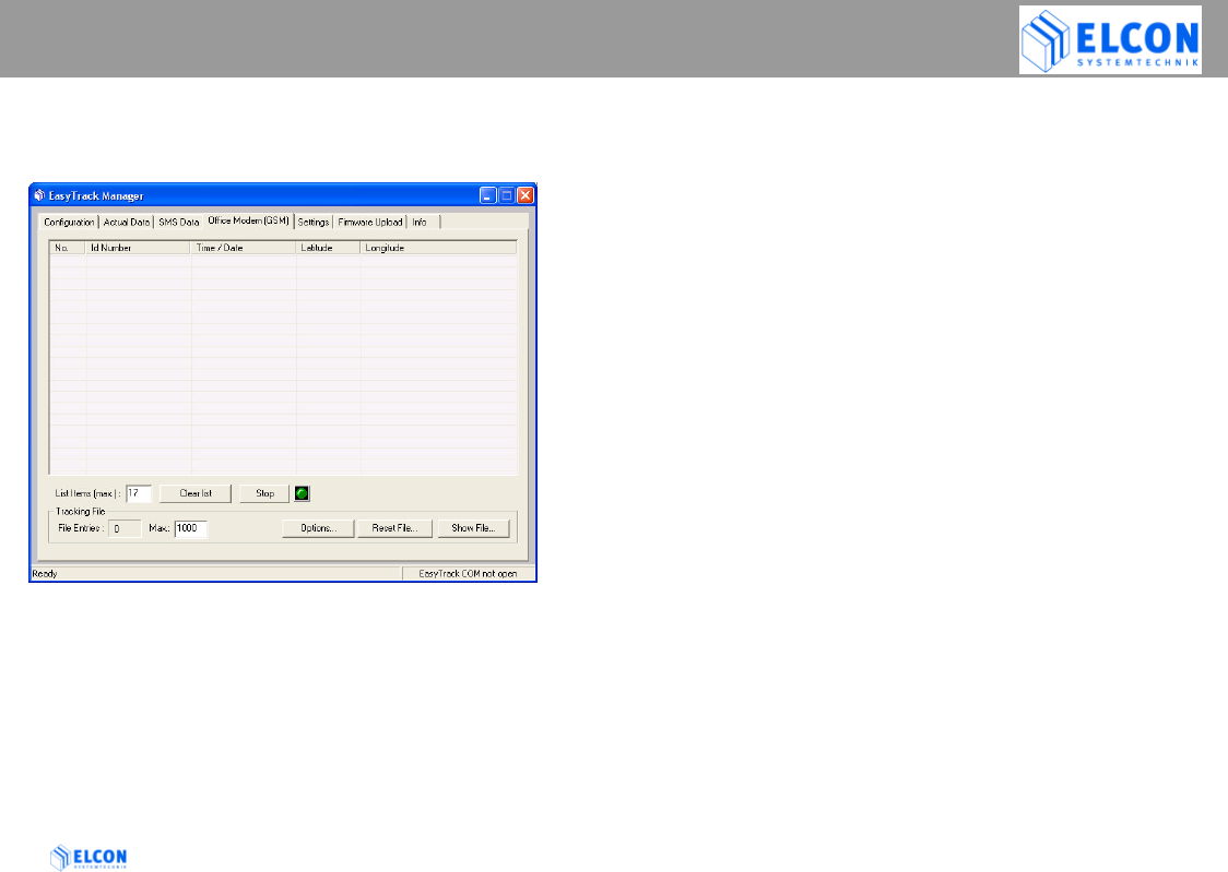
4.7.7 Register Card “Office Modem
(GSM)”
figure 14; Register Card Office Modem (GSM)
On the register card Office Modem (GSM) all SMSs
received by the office modem are displayed within a
list field. In the event of a reboot of the
EasyTrack Manager, all entries stored in this list
before, get lost.
• List Items
In the input field List Items the maximum value for the
entries within the list field can be specified. A maximum of
100 list entries can be displayed.
• Clear List (button)
The button Clear List can be used to delete the content of
the list field.
• Apply (button)
The button apply is indicated in the position of the button
Clear List, if the value in the input field List Items has
been changed. The changed value is adopted by clicking
the button Apply.
• Start [or Stop] (button)
The button Start or Stop can be used to start or to stop
the entries in a so-called Tracking File. If the button Start
is clicked, its activation is indicated by a green LED. If the
writing is deactivated, it is indicated by a red LED.
EASYTRACK MANAGER
EasyTrack Version: 2004/06/17 Page 35
Tracking File
Position, ID number and other selectable parameters
(see Options…) sent by EasyTrack, are stored in a
tracking file. If the EasyTrack Manager receives an
SMS sent by EasyTrack, the data records received
are stored in two files. The file
EasyTrack Manager.CSV stores all data records, no
matter which EasyTrack has sent them. In addition,
the data records received are stored in a file
specified for EasyTrack. This file is automatically
stored under the name, which is indicated in the field
ID Number on register card Configuration. All
tracking files are stored in the folder
…\EasyTrack Manager\TRACK
File Entries
Indicates the number of entries within the
tracking file: EasyTrack Manager.CSV.
Max.
In this input field a maximum value (1000) for
the entries within the tracking files can be
specified. If the value in the input field is
changed, the Apply button appears on the right
hand side of the input field, which has to be
clicked to adopt the changed value.
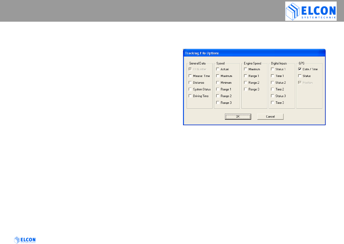
Options…
Via the button Options… the following dialog field can
be opened
in which the options to be included in the tracking files, can
be selected.
ID Number and Position cannot be deactivated and are
therefore always written into the tracking files.
The relevance of the according fields corresponds to those
which are described in 4.7.5 Register Card “Actual Data”.
Note:
After changing the options all CSV files will be initialized.
All the current data from the CSV files will be backed up in
files that have the extension TFB.
EASYTRACK MANAGER
EasyTrack Version: 2004/06/17 Page 36
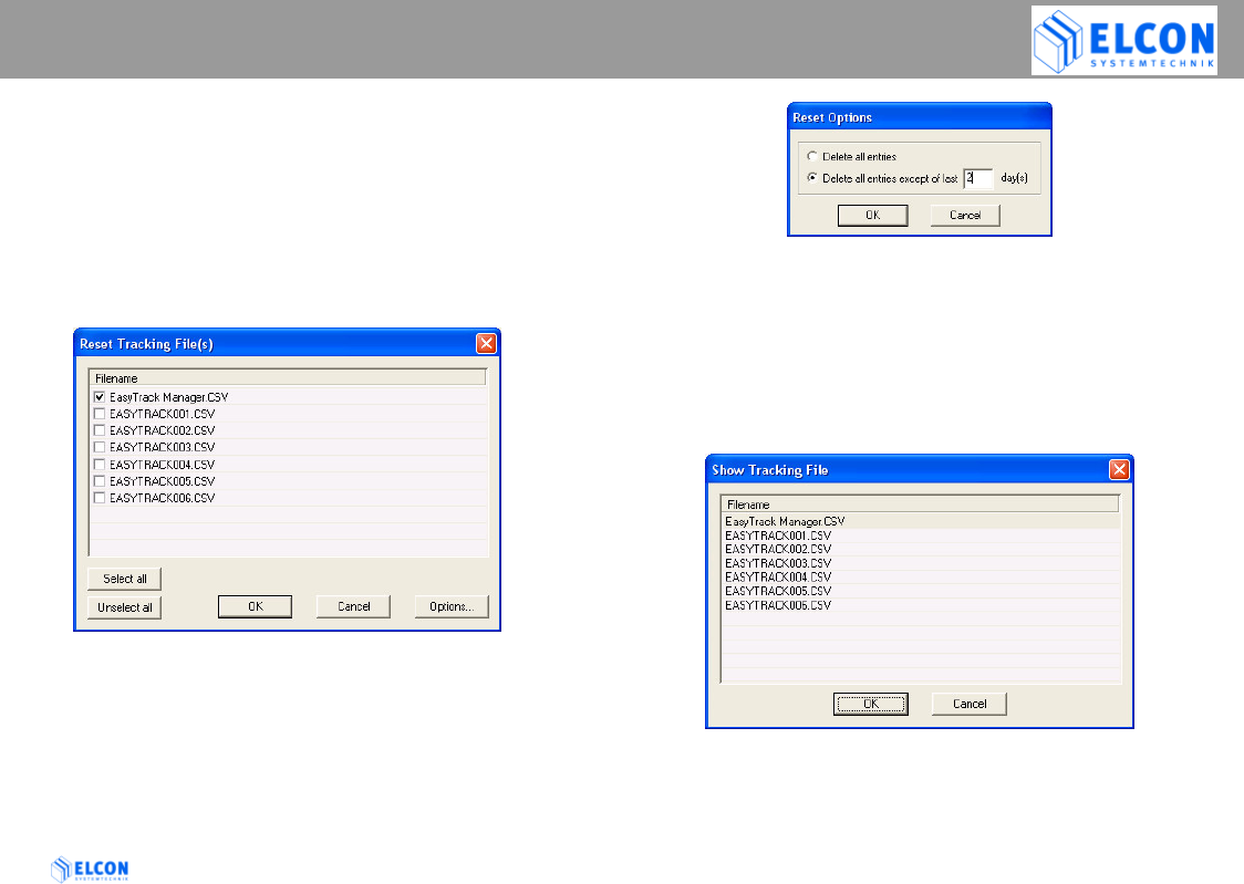
Reset File... (button)
After clicking on the button Reset, the following
dialog field is opened, in which those tracking
files can be selected of which the content is
partly or completely to be deleted. The deleting
of the entries is carried out depending on the
settings indicated in the dialog field Reset
Options. The setting can be carried out via the
button Options….
figure 15; Reset Tracking File(s)
Via the buttons Select all and Unselect all, all
of the check boxes in front of the file name will
be selected or unselected.
figure 16; Reset Options
Show File… (button)
Through the button Show File… a tracking file can be
selected for being displayed. In the list field all files of
the folder …\EasyTrack Manager\TRACK are listed.
Select the corresponding file and click the OK button to
display the selected file. If you don’t want to select a
file, click the button Cancel.
figure 17; Show Tracking File
EASYTRACK MANAGER
EasyTrack Version: 2004/06/17 Page 37
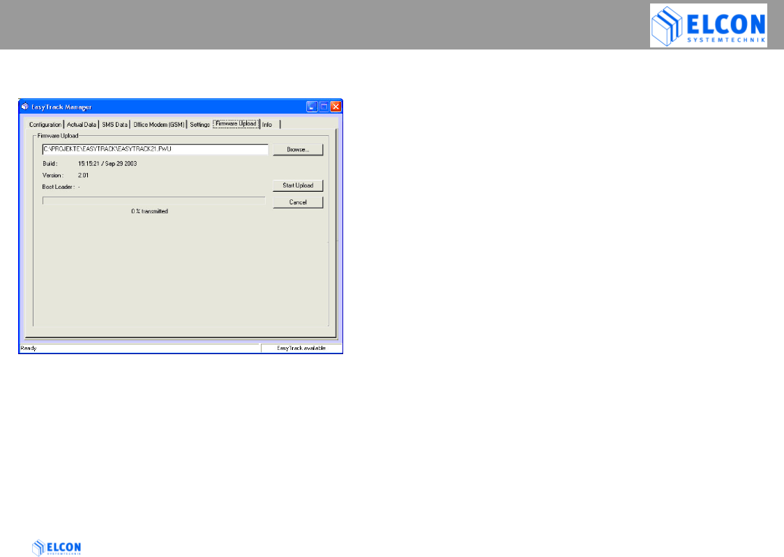
4.7.8 Register Card “Firmware Upload”
If there are firmware updates available for your
device you are able to download them into the
EasyTrack by yourself.
You need to have the EasyTrack connected with the
serial null modem cable to the PC and have made
the correct COM port settings on the register card
Settings.
Choose the supplied file with the help of the Browse
dialog and then Start Upload.
Watch the bottom line of the EasyTrack-Manager, since
useful information about the upload progress are available
here.
After having finished the upload switch to the register card
Configuration page and have a look to the actual status
field Version.
The number of the new firmware should appear when the
EasyTrack has finished rebooting.
4.7.9 Register Card “Info“
The register card Info shows the current version of the
EasyTrack Manager and the link to the internet site of
ELCON Systemtechnik.

EASYTRACK MANAGER
EasyTrack Version: 2004/06/17 Page 38
5 Changed Functionality on Different
Firmware Releases
Changes in Version 1.6
Digital Input 1 has to be activated in order to transmit
periodical SMS.
The EasyTrack has to be continuously powered. This avoids a
GPS "Cold Start" with every trip that you start.
Easy Track will require a few minutes to connect with the GPS
signal.
Note: EasyTrack will draw about 90mA (@12V) current from
your vehicle's battery while it is continuously powered.
Changes in Version 1.7
The EasyTrack will check the level of cellular radio
strength intensity before it will send SMS data.
This firmware change avoids trip data lost in the case where
coverage is below 10%.
The next successful SMS transfer will include all the
summarized information from the previous messages not sent.
Changes in Version 2.0
An update to this firmware release is obligatory for EasyTrack,
thus 1.6 and 1.7 may produce GSM errors after EasyTrack
has started up.
Additionally, included in this firmware is the use of "GPS-
Speed" instead of wheel pulses. If you configure your
EasyTrack "pulse per meter" value to 0 (zero), the EasyTrack
will calculate and transfer trip data based on the speed
information that is provided by the GPS receiver (dependant
on the availability of the GPS signal).
Changes in Version 2.3
GSM module will be forced to search for a network if it fails to do by
itself (targets a bug in the GSM module, that occurs rarely after 2
weeks of continuous operation)
Changes in Version 2.4
The GPS module will be restarted if it fails to send data (issue in winter
with old type of GPS modules)
Changes in Version 2.5
The values for MAX-Speed and MIN-Speed are smooth filtered so
wrong values (i.e. double speed) are avoided
Changes in Version 2.6
Fixed a bug where it could happen, that after switching off the vehicle
in a place where no GSM was available, the unit forgot to send a
message with the next ignition ON

TECHNICAL DATA
EasyTrack Version: 2004/06/17 Page 39
6 Technical Data
This chapter is subject to modifications!
6.1 Technical Description
• serial interface (RS232) for the
operation/connection of display, keyboard, PDA,
bar code scanner and the like.
• GPS positioning (NMEA protocol)
• GSM SMS; in general, data transfer is possible
within the transparent mode
• Measuring of vehicle speed v
• simultaneous speed at time of sending
• average speed v within logging interval ti
• minimum speed v within logging interval ti
• maximum speed v within logging interval ti
• 0 - 30% of maximum speed v in % of ti
• 30.1 - 80% of maximum speed v in % of ti
• 80.1 - 100% of maximum speed v in % von ti
• logging of the idle time in % of ti
• logging of the running time in % of ti
• logging of the motor’s rotational speed
• simultaneous revolution D at time of sending
• average revolution D within logging interval ti
• minimum revolution D within logging interval ti
• maximum revolution D within logging interval ti
• 0 - 30% of maximum revolution D in % of ti
• 30.1 - 80% of maximum revolution D in % of ti
• 80.1 - 100% of maximum revolution D in % of ti
• In addition, other activities, such as those of the brakes,
ignition and headlights, may be logged (three different
signals).

TECHNICAL DATA
EasyTrack Version: 2004/06/17 Page 40
6.2 Technical Data
Approval
EasyTrack has been approved according to the
following guidelines:
1. Type approval for mobile radio equipment of
digital cellular radio telecommunications systems
(GSM and DCS) according to ETSI
2. Type approval for mobile and portable radio
equipment of digital cellular radio
telecommunications systems (GSM and DCS)
according to FCC
3. Type approval according to the directive of the
EEC for the adaptation of the regulations of the
member states about the radio disturbances of
vehicles (e1-Mark and E1-Mark) in compliance
with the directive 72/245/EEC and 95/54/EC
4. Complies with the requirements of electrical safety
according to EN 60950
5. Complies with the requirements of international
transportation of dangerous merchandises on the
road (AVR)
Serial interface RS 232
Software update and data exchange
Power supply
Operating voltage 9 up to 36V
Input electricity max. 2 A
Current consumption
in standby mode 90mA (@12V)
Control unit 8-bit microprocessor
Inputs
• 3 (Status: high / low)
• pulses for road speed
• pulses for revolution
GSM module
• GSM class 4 (2Watt)
• automatic switching to
performance class 5 (0.8W)
• 900/1800/1900 MHz

TECHNICAL DATA
EasyTrack Version: 2004/06/17 Page 41
Enclosure and ambient conditions
Dimensions of enclosure 105 × 106 × 44 mm3
(opt. fastening angle)
Color of enclosure black
Mass of the device 437 g
Temperature for
transport / storage -40 °C ... +85 °C
Scope of
operating temperature -30 °C ... +70 °C
Limitation of GSM modem -30°C ... +60°C
Mechanical strength concerns VDE 0115,
component 200
Oscillation 3 g up to 5 g;
200 Hz per axis
Shock 15 g for 15 ms in
3 axes

ABBREVIATIONS
EasyTrack Version: 2004/06/17 Page 42
7 Abbreviations
GPS Global Positioning System
GSM Global System for Mobile
Communications
NMEA National Marine Electronics Association
RSSI Radio Signal Strength Indication
SMSC Short Message Service Center (GSM)
UTC Universal Time Coordinated (coordinated
world time).

LIST OF FIGURES
EasyTrack Version: 2004/06/17 Page 43
figure 1; insert SIM card 9
figure 2; wiring overview 12
figure 3; front view 16
figure 4; Splash Screen 17
figure 5; repair installation 18
figure 6; main window 19
figure 7; start-up screen 20
figure 8; Register Card Settings 21
figure 9; PUK dialog 22
figure 10; LOG file 24
figure 11; Register Card Configuration 26
figure 12; Register Card Actual Data 31
figure 13; Register Card SMS Data 33
figure 14; Register Card Office Modem (GSM) 34
figure 15; Reset Tracking File(s) 36
figure 16; Reset Options 36
figure 17; Show Tracking File 36

AGENCY INFORMATION AND DEALERS
EasyTrack Version: 2004/06/17 Page 44

EasyTrack Version: 2004/06/17 Page 45
D – 09232 Hartmannsdorf
Obere Hauptstrasse 10
Germany
http://www.elcon-system.de