ELCON Systemtechnik 6618A EasyTrack 6618A User Manual Manual
ELCON Systemtechnik GmbH EasyTrack 6618A Manual
Contents
- 1. Manual
- 2. UsersManual
Manual
PREFACE
EasyTrack Version: 2004/04/29 Page 1
EasyTrack
ELCON BASIC SYSTEM FOR TRACKING DATA
Operating Manual
Order No.: 9537

IMPORTANT NOTES
CAUTION
Statement according to FCC part 15.19:
This device complies with Part 15 of the FCC Rules. Operation is subject to the following two conditions: (1) this
device may not cause harmful interference, and (2) this device must accept any interference received, including
interference that may cause undesired operation.
Statement according to FCC part 15.21:
Modifications not expressly approved by this company could void the user's authority to operate the equipment.
Statement according to FCC part 15.105:
NOTE: This equipment has been tested and found to comply with the limits for a Class B digital device, pursuant to
Part 15 of the FCC Rules. These limits are designed to provide reasonable protection against harmful interference
in a residential installation. This equipment generates, uses and can radiate radio frequency energy and, if not installed
and used in accordance with the instructions, may cause harmful interference to radio communications.
However, there is no guarantee that interference will not occur in a particular installation. If this equipment does cause
harmful interference to radio or television reception, which can be determined by turning the equipment off and on, the
user is encouraged to try to correct the interference by one or more of the following measures:
. Reorient or relocate the receiving antenna.
. Increase the separation between the equipment and receiver.
. Connect the equipment into an outlet on a circuit different from that to which the receiver is connected.
. Consult the dealer or an experienced radio/TV technician for help.
RF Exposure mobile:
The external antennas used for this mobile transmitter must provide a separation distance of at least 20 cm
from all persons and must not be co-located or operating in conjunction with any other antenna or transmitter.

IMPORTANT NOTES
Dear customer:
ELCON mobility would like to thank you for your confidence when purchasing the onboard unit EasyTrack.
This User Manual is intended to help you to activate your EasyTrack and the EasyTrack Manager as quickly as possible.
It provides you with a brief description of setup under Windows® operation systems.
Please make sure to read this user manual carefully, before you bring the unit into service!
Familiarize with the operation and functions of EasyTrack.
Keep the user manual and other descriptive documentation for your reference.
Should you still have questions as this manual might not cover all details, our service partner will be happy to help you.
This user manual is subject to change without notice.
Windows®, Windows NT® and Microsoft® are registered trademarks of Microsoft Corp.
SAFTY INSTRUCTIONS
EasyTrack Version: 2004/04/29 Page 4
Safety Notes
Before installing and starting the device, read the
information given in the operating manual most carefully.
In doing so, you will take advantage of the device’s full
scope of functions and avoid damages due to improper
use.
• The device reflects the current state of the art and
complies with the applicable safety standards.
• Operate the device only in proper condition and strictly
according to the operating instructions.
• Works on the device, including its opening, must only
be done by authorized service personnel.
• For the electrical connection of the device, ensure the
correct line voltage (see chapter Technical Data)!
• Always disconnect the device from mains before you
open it!
• In the event of failure, please contact the manufacturer
or your agency in charge.
• Only end devices complying with the safety standard
according to EN 60950 and bearing the CE-mark, are
permitted to be connected to the interfaces of the
device.
• The end devices must have suitable plug connections,
otherwise appropriate adapters are to be used.
• End devices must only be operated at the interfaces
provided for.
Besides the safety notes mentioned above, you will find
complementary installation instructions in the according
chapters.
This operating manual is subject to change without notice.
For any further questions relating to the
configuration and installation of your device,
please refer to the manufacturer.

TABLE CONTENTS
EasyTrack Version: 2004/04/29 Page 5
1 Introduction .................................................. 6
1.1 Practical application of EasyTrack.................. 6
1.2 Symbols used in this manual.......................... 6
1.3 System requirements for installation............... 7
2 Installation .................................................... 7
2.1 Scope of supply..............................................8
2.1.1 Vehicle equipment.......................................... 8
2.1.2 Office equipment............................................8
2.1.3 Optional Accessories...................................... 9
2.2 Insertion of SIM card......................................9
2.3 Installation position and fastening ................ 10
2.4 Connection options ...................................... 10
2.5 Installation of the device...............................11
2.6 Installation instructions.................................12
2.7 Serial Interface (RS232)............................... 13
3 Relevance of the LEDs............................... 14
4 EasyTrack Manager.................................... 15
4.1 General Information ..................................... 15
4.2 Summary of functionalities ........................... 15
4.3 System Requirements.................................. 15
4.4 First Steps....................................................16
4.5 Installation / Deinstallation............................ 17
4.6 Uninstall EasyTrack Manager.......................18
4.7 Working with EasyTrack Manager................ 19
4.7.1 Starting EasyTrack Manager........................ 19
4.7.2 Presentation of EasyTrack Manager ............ 19
4.7.3 Register Card “Settings”............................... 21
4.7.4 Register Card “Configuration”.......................25
4.7.5 Register Card “Actual Data”..........................30
4.7.6 Register Card “SMS Data”............................32
4.7.7 Register Card “Office Modem (GSM)” ..........33
4.7.8 Register Card “Firmware Upload”.................36
4.7.9 Register Card “Info“......................................36
5 Changed Functionality on Different Firmware
Releases......................................................37
6 Technical Data ............................................38
6.1 Technical Description ...................................38
6.2 Technical Data .............................................39
7 Abbreviations ............................................. 41

INSTRUCTION
EasyTrack Version: 2004/04/29 Page 6
1 Introduction
1.1 Practical application of EasyTrack
EasyTrack is a most efficient positioning system
which is able to perform the parallel processing of up
to 12 GPS satellite signals and to send data relating
to the vehicle and its position to a central
office/transport company via GSM radio network. The
mobile device is part of a modern information and
monitoring system consisting of both hard and
software components serving for:
• innovative transport companies
• their partners
• and customers
The use of EasyTrack enables suppliers, transport
companies and customers to get essential
information about the vehicles in service as well as
their cargo and position via on-line access.
1.2 Symbols used in this manual
Warning
contains important information on operation of your
EasyTrack and EasyTrack Manager.
Caution
must be observed to avoid any problems on your
PC or damage of your EasyTrack.
Notes contain information on operation of your
EasyTrack and EasyTrack Manager.

INSTALLATION
1.3 System requirements for installation
The on-board voltage is permitted for 9 … 36V.
You can choose one of three different ways to
connect the EasyTrack to your vehicles power
cables:
1) If you connect the power pins and "Dig. Input 1"
to constant power, the EasyTrack will send
always SMS using the predefined interval
setting.
2) If you connect the power pins and "Dig. Input1"
to Ignition, the EasyTrack will send interval
SMS only if Ignition is ON. With every power
ON you will have no GPS data in the SMS until
GPS position is fixed.
3) If you connect the power pins to constant
power and "Dig. Input 1" to Ignition, the
EasyTrack will send interval SMS only while
Ignition is ON.
The GPS module is powered continuously, thus
a GPS position can be sent with every SMS
(depends on GPS availability) Note: The
EasyTrack will always draw about 100mA from
your vehicles battery!
The GPS antenna must be installed in such a way that its
free line to the sky is ensured.
The GSM antenna must be installed in such a way that a
free connection to the GSM net can be established and
its shielding by metal parts is excluded.
2 Installation
Before you start the installation of the device make sure to
follow the best sequence for you to work on.
For a normal setup we recommend this sequence:
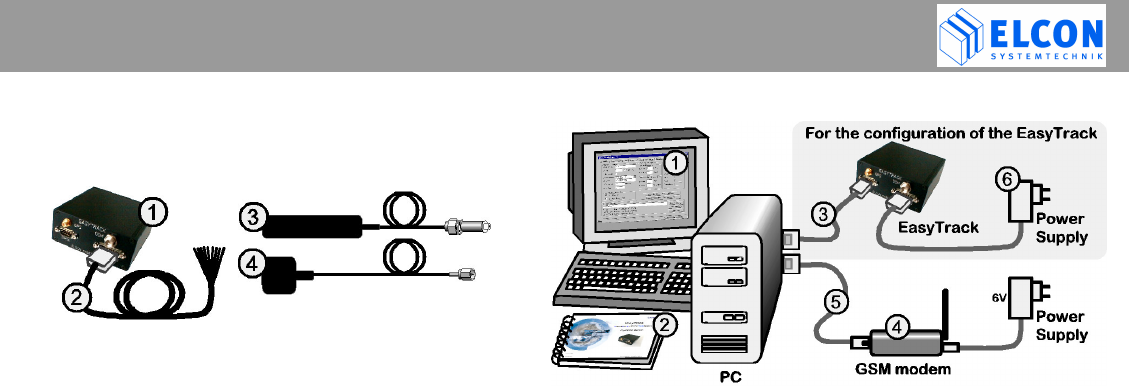
1) Operate the EasyTrack first close to your PC using the
optional power supply for EasyTrack.
2) Configure the EasyTrack with your specific data
(EasyTrack-ID, PIN, vehicle sensor information,
interval time,…). See chapter 4.7.3
3) Install the EasyTrack inside the vehicle and test it. See
chapter 2.5
If you own a laptop which is capable of running the
EasyTrack-Manager, we recommend you to install the
EasyTrack inside the vehicle and make the configuration and
test on board.
INSTALLATION
2.1 Scope of supply
2.1.1 Vehicle equipment
1. EasyTrack device
Order no. 6618
2. Cable loom power / input
Order no. 9409
3. GSM antenna 1)
Order no. 9411
4. GPS antenna 1)
Order no. 9410
1) Instead of two separate antennas, a
combined GSM/GPS antenna can be
chosen.
Order number: 9507
The illustrations on the following images
may differ
2.1.2 Office equipment
1. PC software EasyTrack Manager
for Microsoft Windows® Order no. 9542
2. EasyTrack Operating Manual
Order no. 9537
3. Null modem cable 3m
Order no. 9541
4. GSM/GPRS Office Modem (Triband)
Order no. 9372
5. Connecting cable for office modem 1.8m
D-Sub connector, male/female, 9 pin.
Order no. 9512
6. Power Supply for EasyTrack
Order no. a0075
INSTALLATION
2.1.3 Optional Accessories
If your PC has no serial interface (RS232), but a USB
interface, you may realize the connection to
EasyTrack also via a USB converter.
• USB converter
including serial cable, adapter and driver CD
Order no. 9520
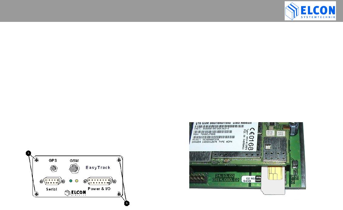
2.2 Insertion of SIM card
Use a normal 3V or 5V SIM card for mobile phones
Before installing EasyTrack, the SIM card must be
inserted into the device. For this purpose, open the 4
screws at the front side of the device.
Pull the circuit board out of its enclosure. Afterwards insert
the SIM card you received from the service supplier with its
beveled edge at the correct position into the device (see fig.
1). If you have received a check card format SIM card,
please remove the smaller section.
In order to avoid any destruction of EasyTrack, the
device must be switched off!
To reduce the risk of damaged equipment. Before any
part of the circuit board is touched be sure to discharge
yourself by touching a grounded surface of the device!
figure 1; insert SIM card

INSTALLATION
2.3 Installation position and fastening
The device is contained in a small box, which may be
attached to a surface using 4 screws at the fastening
points.
The device has neither a keyboard nor a display and
can therefore be installed in a concealed position.
As to the installation of EasyTrack, any installation
position is allowed, as long as you choose a dry
place where no person can be injured.
Be sure the cables are tied closely to the easy track
to prevent excessive vibrating of the cables, and
possible damage to the connectors.
Do not install the cables in such a way that they are
tight or strained, allow some slack to avoid potential
cable damage
Windows®, Windows NT® and Microsoft® are registered trademarks of
Microsoft Corp.
2.4 Connection options
Digital Inputs (9…36V):
Connect the positive line to (a) and the ground to (b)
Signals with the same name are already connected inside
the EasyTrack.
* on some (old) cables pin 4 was colored brown
POWER & I/O
Supply + (9...36V)
Supply + (9...36V)
Dig. In 1 (a)
Dig. In 1 (b)
Dig. In 2 (a)
Dig. In 2 (b)
Dig. In 3 (a)
Dig. In 3 (b)
V-PULSE Input
RPM-PULSE Input
Supply GND
Supply GND
view to the solder
side of the
cable connector
red
black
orange
blue
purple (brown*)
yellow
grey
green
pink
brown
1
9
2
10
3
11
4
12
5
13
6
14
7
15
8

INSTALLATION
2.5 Installation of the device
Safety notes:
Upon the installation of EasyTrack, the
following safety notes must be observed!
• When disconnecting the negative pole of the battery, the
safety instructions of the automobile manufacturer must
be observed.
• When drilling holes for the fixing of EasyTrack, it must be
paid attention to the fact that neither parts of the vehicle
nor electric cables are damaged.
• The cross section of the positive and negative cable must
be no less than 0.5 mm2.
• In the event of faulty installation, operational malfunctions
of the vehicle’s electronic system or of the EasyTrack may
occur.
• The manufacturer’s supplied cables must be used when
connecting EasyTrack to the connection points
recommended by the vehicle manufacturer.
• For safety reasons we recommend that you install the
GSM antenna at least one meter away from any persons
in the driver's cabin
INSTALLATION
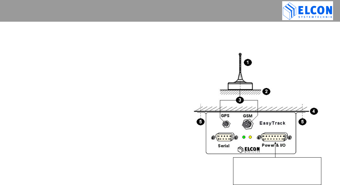
2.6 Installation instructions
See figure 2; wiring overview
• Select any installation position in the vehicle.
• Bore the fastening holes for the fastening angles.
Observe the above mentioned safety
instructions!
• Fix the EasyTrack at the vehicle.
• Establish the cable connection between
EasyTrack and vehicle.
To avoid short circuits, make sure that the
cables neither jammed nor cut off by flexible
vehicle parts!
• Selection of a suitable position of the GPS/GSM
dual-function antenna.
Undisturbed satellite communication must be
ensured!
• Bore the fastening holes and establish the cable
grommet for the GPS/GSM dual function antenna.
Observe the above mentioned safety
instructions!
• Establish the cable connection between the EasyTrack
and the GPS/GSM dual-function antenna.
Bend radius must be minimum 1cm!
figure 2; wiring overview
GPS/GSM dual-function antenna
Top of vehicle
GPS/GSM cable
Car body
Fastener for the fixing
•
Power input of EasyTrack
• Input of v pulse and RPM pulse
• 3 digital input
•
w
iring cable ( )
INSTALLATION
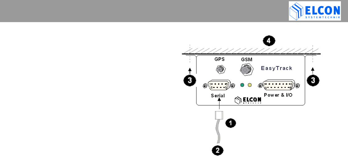
2.7 Serial Interface (RS232)
• Via the serial interface RS232 it is possible to
connect a PC or notebook to configure EasyTrack.
• The end devices must have compatible plug
connectors. Their connection must be realized
only by means of the transmission cable
recommended by the manufacturer.
• It might be necessary to use suitable adapters.
• The end devices must only be connected to the
interface provided for.
Serial interface cable (null modem cable)
Service/configuration
(possible connections: PC, Notebook)
Fastener for the fixing
Car body

FUNCTION OF LEDS
EasyTrack Version: 2004/04/29 Page 14
3 Relevance of the LEDs
At the front side of the device, a green and a yellow
LED indicate the operational status of EasyTrack.
Immediately after switching on the EasyTrack, its
boot loader is started which allows the upload of new
EasyTrack firmware. During this time (approx. 5
seconds) both LEDs flash rapidly. The yellow LED
indicates that the hardware check is carried out.
Following the hardware check, the yellow LED is
turned off and the green LED flashes slowly. In this
case the device is ready to operate - but it is still
waiting for a valid GPS-position. The green LED will
stay on permanently once the GPS position
connection has been established.
The yellow LED indicates the state of Dig. Input 1. If
you have connected the EasyTrack to permanent
power and your vehicles ignition is connected to Dig.
Input 1, the Yellow LED will be permanently on when
activated by the ignition. (SMS transfer enabled) and
turn off while ignition is off (SMS disabled).
Additionally there is an internal activity of the GSM-Modem
displayed by flashing on the yellow LED.
The duration of the flashing helps you to determine the
actual operation of the GSM-Modem:
short (approx. 0,5s): EasyTrack checks incoming SMS.
medium (approx. 2..4s): Sending SMS
long (> 6s) : SMS cannot be sent

EASYTRACK MANAGER
EasyTrack Version: 2004/04/29 Page 15
4 EasyTrack Manager
4.1 General Information
EasyTrack Manager is a software program, which
works on a standard PC, equipped with Windows 9x /
NT 4.0 / Windows 2000 or Windows XP. To run this
program, no special hardware is required. The
program name of the EasyTrack Manager is:
EasyTrackManager.EXE. The program
EasyTrack Manager consists of 2 files: the
executable file EasyTrackManager.EXE and the
initialisation file EasyTrackManager.INI.
4.2 Summary of functionalities
• Writing configuration data into the EasyTrack,
• Reading configuration data from the EasyTrack
• Receiving SMS data from EasyTrack via GSM
office modem
• Sending SMS data via GSM office modem
• Logging data from EasyTrack within a tracking
file for displaying the coordinates within a map
• Logging data from EasyTrack and other
sources of informations within a LOG file
4.3 System Requirements
Hardware:
PC-compatible computer with:
• Intel® Pentium® Processor or compatible with 266 MHz
or higher
• 32 MB RAM
• 5 MB of disk space
• 640 x 480 minimum screen resolution
• minimum one serial port
Software:
The EasyTrack Manager is a 32-bit application. It runs on
Microsoft®
• Windows 95 / 98 / 98 SE
• Windows NT 4.0
• Windows 2000
• Windows XP
Intel® and Pentium® are registered trademarks of Intel Corp.
Windows®, Windows NT® and Microsoft® are registered trademarks of Microsoft Corp.

EASYTRACK MANAGER
Serial Power & I/O
EasyTrack
GPS GSM
1
1
5
6
9
8
9
15
4.4 First Steps
figure 3; front view
• Make sure that your PC and the EasyTrack are
switched off.
• Connect your EasyTrack to the main power supply
connector and have a look on the LEDs to
check the proper operation of EasyTrack. Directly
after power-up, both LEDs flash quickly for the
period of 5 seconds. Afterwards, the green LED
indicates the hardware status, while the yellow
LED indicates the communication status with the
GSM modem. The green LED flashes slowly
(1 s on/1 s off) if everything is in order.
• Plug one end of the null modem cable supplied into the
appropriate port of the EasyTrack and the other end
into a free serial port (e.g. COM1 or COM2) on your PC.
• Plug the antenna connector for GPS into port .
• Plug the antenna connector for GSM into port .
• Switch the computer on and follow the instructions of the
chapter: Installation
EASYTRACK MANAGER
EasyTrack Version: 2004/04/29 Page 17
4.5 Installation / Deinstallation
To install EasyTrack Manager on your computer
1) Start Windows®
2) Insert the EasyTrack Manager CD into the CD-ROM
drive, and then follow the directions on the screen.
If the installation program does not start
automatically, click on Start and then on Run. In the
Run dialog box, enter E:\SETUP.EXE in the
command line and click on the OK button. If your
CD-ROM drive has a drive letter other than E,
substitute the appropriate letter.
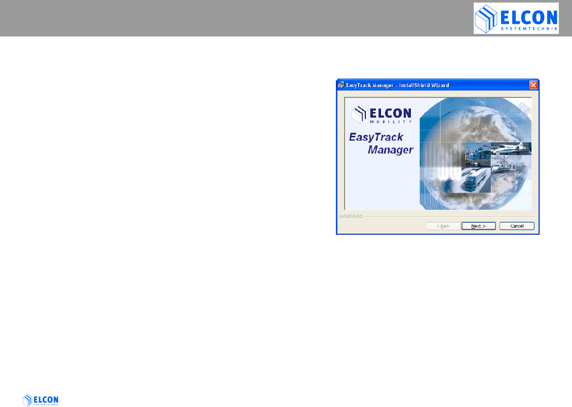
The installation program starts. The subsequent
procedure is menu-driven. The remainder of the
installation is automatic, so that it is not required to
enter any further information.
figure 4; Splash Screen
3) Select the preferred options and follow the on-screen
instructions.
4) After the EasyTrack Manager software has been
successfully installed, click on the button Finish to
exit the installation program.
EASYTRACK MANAGER
4.6 Uninstall EasyTrack Manager
To uninstall EasyTrack Manager on your computer, click
on
Start Program Files ELCON mobility
EasyTrack Manager Uninstall EasyTrack Manager
or start the SETUP.EXE of EasyTrack Manager from the
CD-ROM and follow the on-screen instructions.
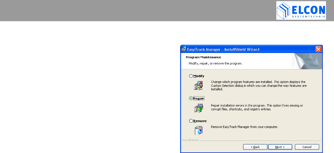
Note:
If the EasyTrack Manager does not start or run properly,
try to repair your installation by calling the SETUP.EXE of
EasyTrack Manager from the CD-ROM. Select the Repair
button in the following dialog. This option fixes missing or
corrupt files, shortcuts, and registry entries.
If you need to update or repair the EasyTrack Manager all
CSV files (for Mappoint) and also the LOG file will remain
on your computer. So no data will get lost.
figure 5; repair installation
EASYTRACK MANAGER
4.7 Working with EasyTrack Manager
4.7.1 Starting EasyTrack Manager
Click one after the other on the following buttons on your
task bar:
Start Program Files ELCON mobility
EasyTrack Manager EasyTrack Manager,
to start the program, or do a double click on the
EasyTrack Manger symbol in the new program group.
Click on Start and then in succession
Program Files ELCON mobility
EasyTrack Manager EasyTrack Manager
to start the program or do a double click onto the
EasyTrack Manager symbol which is displayed on the
desktop screen.
4.7.2 Presentation of EasyTrack Manager
The application has been developed for a monitor
resolution of at least 640*480 pixels. After the program
start, a start-up sequence is displayed for approx. 5 sec.
After that, the main window is opened with a number of
individual work packages implemented on register cards.
For the EasyTrack configuration as well as for the
configuration of the application, the following register
cards are available:
• Configuration
• Actual Data
• SMS Data
• Office Modem (GSM)
• Settings
• Firmware Upload and
• Info.
figure 6; main window

EASYTRACK MANAGER
4.7.2.1 Start-Up Sequence
For the start-up sequence, the EasyTrack Manager shows
the following message box for 5 seconds. The displaying
of the start-up window can be terminated by pressing the
left mouse key within the displaying window. As an
alternative, the ESC key can be used. After the start-up
sequence, the last used register card is shown.
figure 7; start-up screen
4.7.2.2 Status Bar
The status bar is displayed in the lowest line of the
application window. On the right side of the status bar you
can see the status of the communication to an EasyTrack.
The following states are considered:
EasyTrack COM not open The COM port indicated on
the register card Settings is
not open.
EasyTrack not available The interface indicated could
be opened, however, it
cannot communicate with an
EasyTrack.
EasyTrack available Communication with an
EasyTrack exists.
4.7.2.3 Use of the keyboard
Via the TAB key the name of a register card can be
selected. If one card has shown the input focus as
displayed in figure 6, another register tab can be selected
via the right or left cursor keys. The controls on one
register card can be chosen by the TAB key.
If the input focus is on a combo box, the list box of this
combo box is about to be made visible with the key F4.
EASYTRACK MANAGER
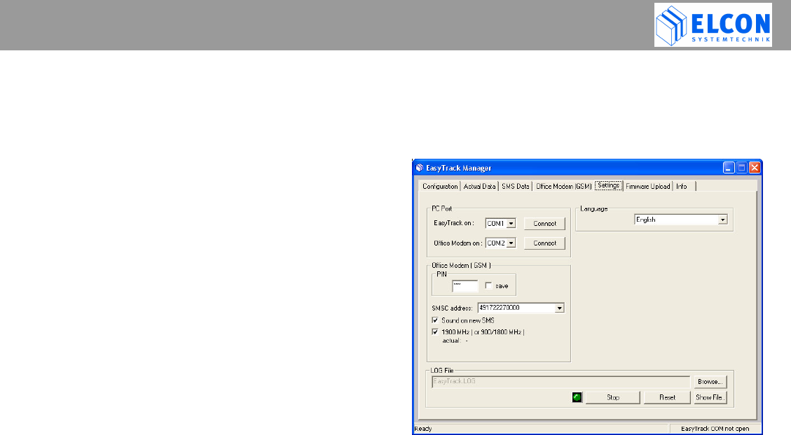
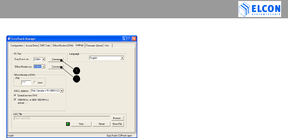
4.7.3 Register Card “Settings”
figure 8; Register Card Settings
• PC Port
After the first start of the EasyTrack Manager, the
application is not connected automatically to a COM
port. The user has to define, which COM port shall be
used by the application. After the definition of the COM
port, press the appropriate Connect button to connect
the COM port to the EasyTrack (see ) or the GSM
office modem (see ). If a connection has been
established, the appropriate button text is switched to
Disconnect. All COM ports are closed automatically if
the application is closed.
• Language
In the field Language one of two national languages
(English and German) can be chosen to be used by the
application for the text display and file entries.
• Office Modem (GSM)
The GSM modem is a GSM900/1800/1900 Phase II+
device. 1900MHz band is used in North America; see
checkbox 1900MHz.
PIN
Depending on the type of your SIM card, it may be
protected against misuse by a four- to eight-digit PIN.
If required, enter the according PIN, which is stored
on the SIM card, into the input field. If no pin is
required, select the checkbox automatic