ELITEGROUP COMPUTER SYSTEMS E11IS Notebook User Manual E11IS2 English FCC ID
ELITEGROUP COMPUTER SYSTEMS CO., LTD Notebook E11IS2 English FCC ID
UserManual.wiki
>
ELITEGROUP COMPUTER SYSTEMS
>
E11IS User Manual
User Manual
Navigation menu
Upload a User Manual
Namespaces
Wiki Guide
HTML
PDF
Info
Views
User Manual
Discussion / Help
Navigation


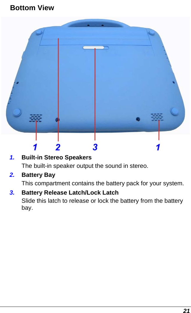

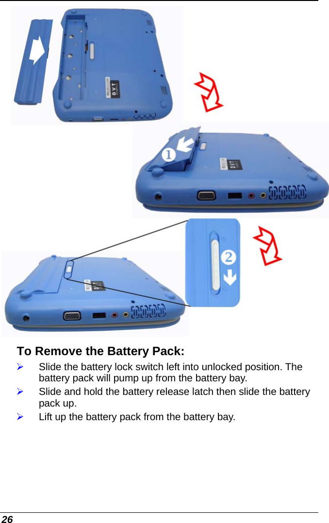
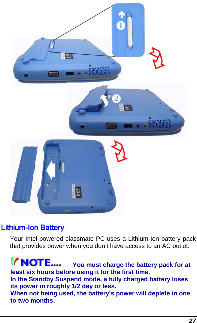

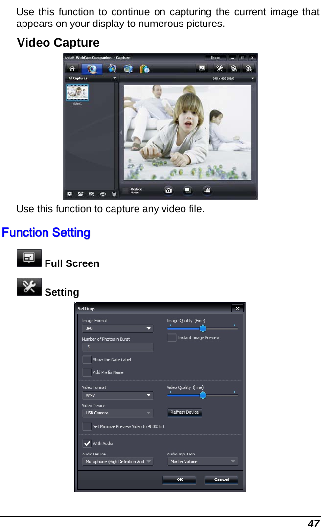
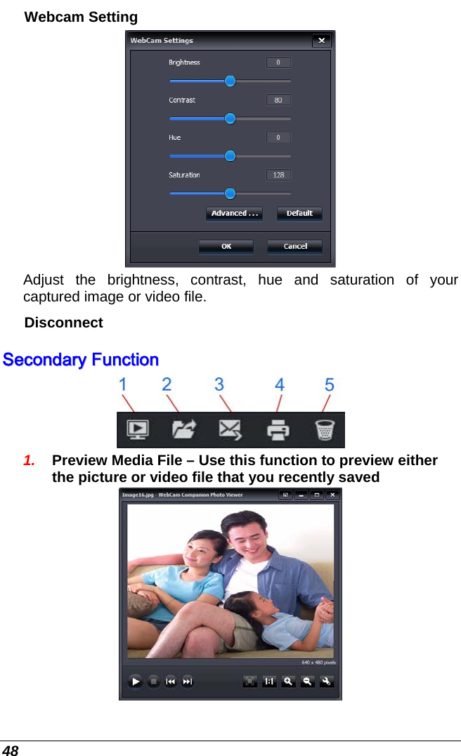
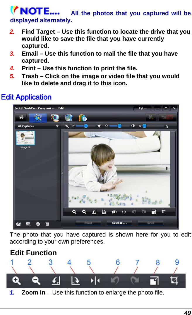
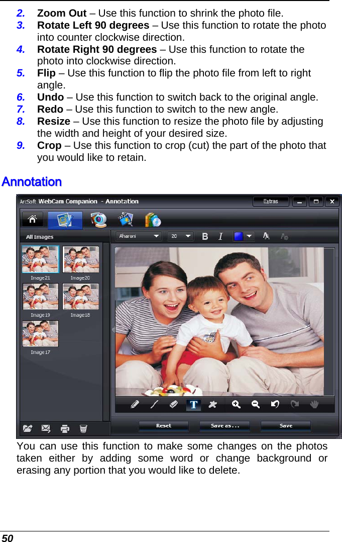
![36 RReesseettttiinngg tthhee SSyysstteemm After installing a software application package, you may be prompted to reset the system to load the changed operating environment. To reset the system, or “reboot,” press the [Ctrl]+[Alt]+[Delete] keys simultaneously. This is known as “warm boot.” This key combination acts as “software” reset switch when you encounter hardware or software problems, which lock up the Intel-powered classmate PC. If this key combination does not shut down the Intel-powered classmate PC, you can reset the computer by using the Intel-powered classmate PC’s power button. Should the computer lock up for some reason, pressing this button powers the system off. GG SSeennssoorr ((OOppttiioonnaall)) The Hard-Disk Drive (HDD) Protection application protects the system’s HDD from damage caused by sudden harmful shocks. It monitors system movements that exceed the defined shock threshold. Once a shock is detected, the application instructs the HDD to temporarily park its heads which protects against potential damage the drive.](https://usermanual.wiki/ELITEGROUP-COMPUTER-SYSTEMS/E11IS/User-Guide-1410180-Page-42.png)