ELITEGROUP COMPUTER SYSTEMS GWS-HZW1 Home Gateway User Manual home lake cover page OL 2018 06 05
ELITEGROUP COMPUTER SYSTEMS CO., LTD Home Gateway home lake cover page OL 2018 06 05
User Manual
i
Table of Contents
Product Introduction 1
Model 1
What’s in the Box? 2
Installing Micro SIM Card 3
Steps 3
Power on your device 4
Steps 4
Product Feature 5
LED Indicator Behavior 6
Using GWS-HZW1 7
Powering the System 7
System Login 7
Program Examples 16
Intel Quark - Programming GPIO From Linux 16
Digital GPIO - Sysfs Interface 16
GPIO Information 16
Examples For LED GPIO Control Method 16
產品介紹 18
型號 18
包裝內容 19
安裝MicroSIM卡 20
步驟 20
ii
設備供電 21
步驟 21
產品規格特色 22
指示燈行為 23
使用GWS-HZW1 24
系統啟動 24
系統登錄 24
網路設定 26
WiFi網路設定 29
Bluetooth設定連結 31
4GLTE網路設定 32
程式範例 33
IntelQuark-ProgrammingGPIOFromLinux33
DigitalGPIO - Sysfs Interface 33
GPIOInformation 33
L E D G P I O 的 控 制 方 法 舉 例 3 3
注意事項 35
1
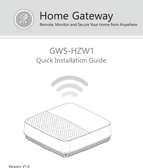
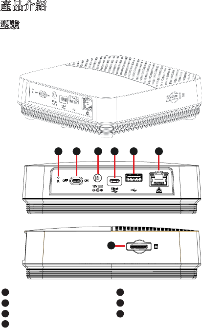
Product Introduction
Model
GWS-HZW1
Reset
Power Switch
DC Input Port
Debug Client Port
5
5
7
7
1
1
2
2
3
3
4
4
6
6
USB Port
LAN Port
SIM Card Slot
2
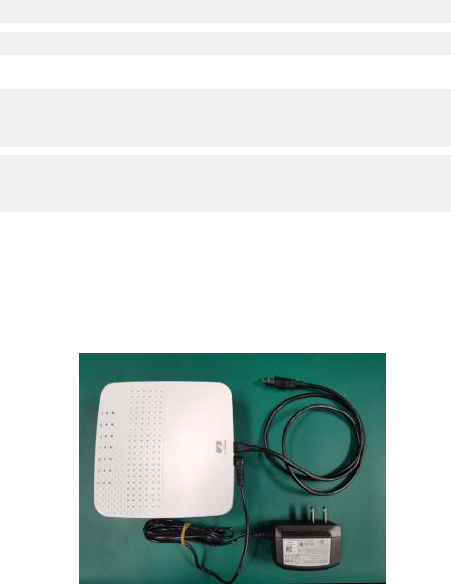
What’s in the Box?
GWS-HZW1 Home Gateway
User Quick Guide
Power Adapter (12V DC, ASIAN POWER DEVICES INC.
WA-24Q12FU) *
Note: * Only the enclosed adapter can be used to this
device.
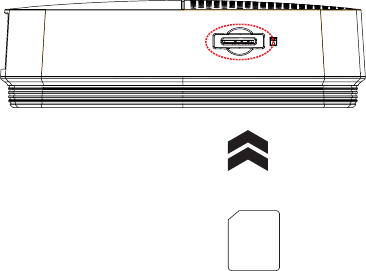
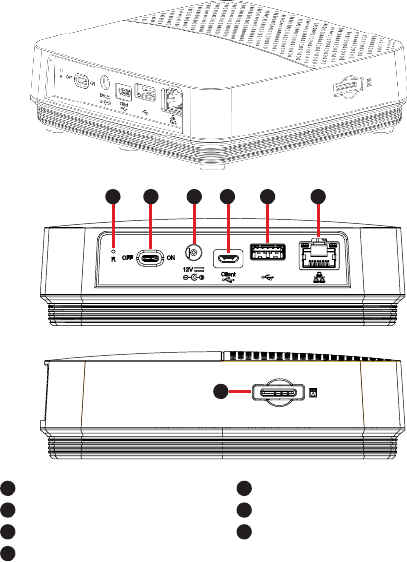
3
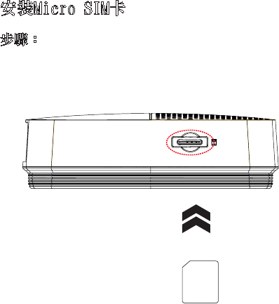
Installing Micro SIM Card
1. Locate the SIM card slot.
2. Insert the Micro SIM card gently.
Steps:
4
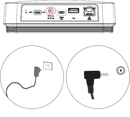
Power on your device
1. Plug the adapter to AC wall outlet.
2. Connect the Power adapter to the device.
3. Turn the power switch to the ON position.
Note: * LED power indicator in RED, gateway in boot
up stage.
Steps:

5
Product Feature
Connectivity
LAN port, support WiFi and Bluetooth
Interface
DC-in port, USB port, SIM card slot, reset, LAN port,
Debug client port, power switch
Dimensions & Weight
Dimension: 128 × 117 × 38.7 mm
Weight: 335 g
Environmental Conditions
Operational temperature range:
0°C to +45°C (32°F to 113°F)
Storage temperature range:
-20°C to +60°C (-4°F to 140°F)
6
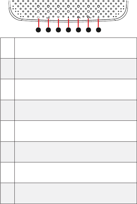
LED Indicator Behavior
No. LED Color Function
1 Power Blue/Red
1. Power on => Red
2. Boot up and OS is work-
ing => Blue
2 LTE Blue Enable => Blue
3 WiFi Blue Enable => Blue
4 BLE Blue Enable => Blue
5 Zigbee Blue Enable => Blue
6 Z-Wave Blue Enable => Blue
7 Battery Blue
1. Charging => Blue
2. Charging complete =>
off
6 7
15
23 4
7
Using GWS-HZW1
Login as ‘root’ and then issue a ‘poweroff’ or ‘reboot’
command.
Powering the System
root@WR-IntelligentDevice:~# poweroff
Or send ssh remote command to GWS-HZW1.
root@WR-IntelligentDevice:~# reboot
ecs@ecs-IoT:~$ ssh root@192.168.0.1 poweroff
root@192.168.0.1’s password:
ecs@ecs-IoT:~$
ecs@ecs-IoT:~$ ssh root@192.168.0.1 reboot
root@192.168.0.1’s password:
ecs@ecs-IoT:~$
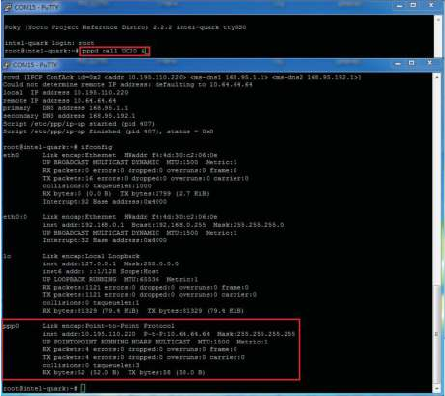
The system can be accessed and controlled via a Linux
shell called ‘console’ by using micro-USB. The users may
procedures of the following sections.
System Login
8
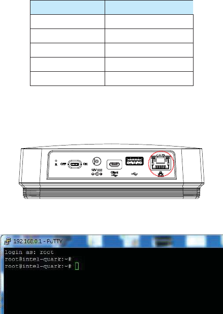
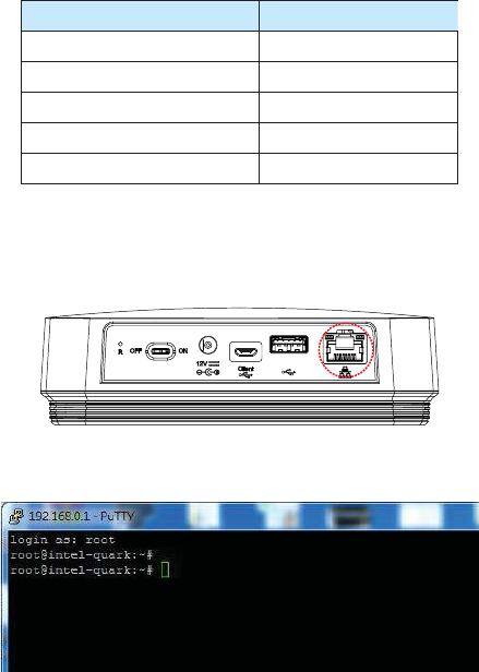
If using serial console or terminal emulator, the serial port
settings are
Setting Value
Baud 115200
Parity No
Data Bit 8
Stop Bit 1
Flow Control No
When using Secure Shell (or SSH), you can establish the
communication through LAN 1 port, which is the RJ45 port
right next to the USB port and is assigned with an IP address
Fig 1: the location of LAN 1 port
The login account used here is ‘root’.
9
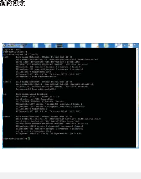
networking (LAN) of GWS-HZW1.
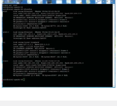
If you use a serial console, you might setup networking by
manual. Otherwise the networking is workable.
Step 1. Check the network interfaces by executing the
Step 2. Activate the network interface (e.g. eth0).
Step 3. If the interface matching failed, please edit /etc/
network/interfaces directly and then either restart the
service or reboot the system to make the change effect.
10
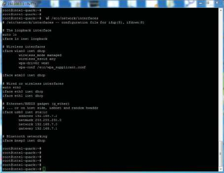
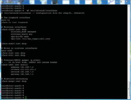
The way to set DHCP connection is as follow:
vi /etc/network/interfaces
11
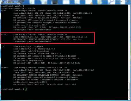
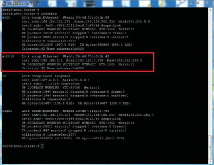
The way to set static IP connection is as follow:
eth0:0
12
Step 1. Check the network interfaces by executing the
command.
-
Step 2.
-
- connmanctl services
- connmanctl
- agent on
-

13

14
Input the following commands.
Send shell command.
(Connect)
- bluetoothctl
- agent on
- power on
- scan on
- scan off
- devices
- pair BT MAC Address
- trust BT MAC Address
(Disconnect)
- disconnect BT MAC Address
- remove BT MAC Address
15
Input the following commands.
Choose one ot the following three commands(1~3) based
on the corresponding LTE module.
- 1.
2. pppd call UC20 & --> QuecTel UC21-JMINPCIE
3. pppd call UC20 & --> QuecTel EC21-AU
-
16
Program Examples
For GWS-HZW1 board, most of the GPIO features can be
achieved through the Linux Sysfs interface and can be
you how to activate some features by using some simple
shell commands. Of course, besides using shell commands,
operations. All the concerned programs can be written in
your desired language.
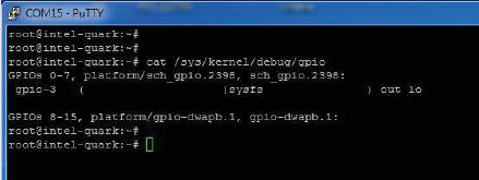
Following commands can display the system’s GPIO
information, showing which IO port is being assigned to
which module or Sysfs.
Command : cat /sys/kernel/debug/gpio
- Set GPIO pins

17
- Set the direction of GPIO(INPUT or OUTPUT)
- Set GPIO swtich
- Inquire the current GPIO value
18
產品介紹
重置孔
電源開關
電源輸入插孔
客戶調試端口
5
7
1
2
3
4
6
USB端口
網絡端口
SIM卡插槽
GWS-HZW1
型號
6
7
1 5
2 3 4

19
包裝內容
GWS-HZW1 家用閘道器
電 源 供 應 器 ( 1 2 V D C , A S I A N P O W E R D E V I C E S I N C . W A -
24Q12FU)*
快速使用指南
注意:*本產品僅可使用隨附的電源供應器。
20
安裝Micro SIM卡
步驟:
1.對準設備的SIM卡插槽。
2.輕輕地插入SIM卡。
21
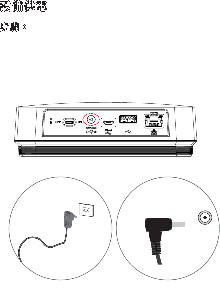
設備供電
步驟:
1.將電源供應器插入電源插座。
2.將電源供應器插入本機電源插孔。
3.將電源開關撥至ON位置。
注意:*LED電源指示燈為紅色,且閘道器處於啟動狀態。
22
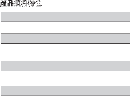
產品規格特色
連接方案
網絡端口,支援WiFi,藍牙
支援介面
DC-in供電插孔、SIM卡槽、重置孔、網絡端口、電源開關、
客戶調試端口
產品尺寸、重量
尺寸:128 × 117 × 38.7 mm
重量:335克
環境條件
操作溫度:0°Cto+45°C(32°Fto113°F)
儲存溫度:-20°Cto+60°C(-4°Fto140°F)
23
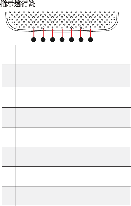
指示燈行為
序
號
LED指示
燈顏色 功能
1電源指
示燈 藍燈/紅燈
1. 通電 => 紅燈亮
2. 啟動,系統運行中=>藍
燈亮
2LTE指示
燈藍燈 開啟 => 藍燈亮
3WiFi指
示燈 藍燈 開啟 => 藍燈亮
4藍牙指
示燈 藍燈 開啟 => 藍燈亮
5Zigbee
指示燈 藍燈 開啟 => 藍燈亮
6Z-Wave
指示燈 藍燈 開啟 => 藍燈亮
7電池指
示燈 藍燈 1. 充電 => 藍燈亮
2. 充電完成 => 燈滅
6 7
15
23 4
24
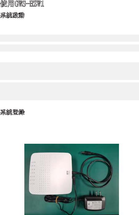
使用GWS-HZW1
以‘root’帳號登錄,然後執行‘poweroff’或‘reboot’
指令。
系統啟動
root@WR-IntelligentDevice:~# poweroff
或發送ssh遠程指令給GWS-HZW1。
root@WR-IntelligentDevice:~# reboot
ecs@ecs-IoT:~$ ssh root@192.168.0.1 poweroff
root@192.168.0.1’s password:
ecs@ecs-IoT:~$
ecs@ecs-IoT:~$ ssh root@192.168.0.1 reboot
root@192.168.0.1’s password:
ecs@ecs-IoT:~$
使用micro-usb通過稱為
‘
console(控制台)’的Linux
shell可進入及控制系統。使用者可調用Linux指令來配
置以下程式中的某些內容。如下圖:
系統登錄
25
若使用串口console或終端模擬器,串口console的設定如
下:
設定 值
Baud(波特) 115200
Parity(奇偶性) No
DataBit(數據位數) 8
StopBit(終止位數) 1
FlowControl(流程控制) No
若使用SecureShell(稱為SSH),它將偵聽LAN1,IP為
192.168.0.1。LAN1為靠近USB插孔的RJ45連接器。
圖為LAN1連接器的位置
登錄的帳戶為‘root’。
26
步驟3.若設定不匹配,請編輯/etc/network/interfaces
以便在啟動時生效。
以下步驟用來設定GWS-HZW1的局域網(LAN)。如果
GWS-HZW1的網路無法正常使用,您應該需要使用串口
console,以手動的方式來設定或啟動網路。
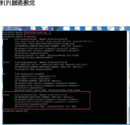
步驟1.檢查網路介面。Command:ifconfig
網路設定
步驟2.啟用網路介面,e.g.eth0。若無eth0,請使用圖
中command啟動。
27
DHCP連線的設定方式如下:vi/etc/network/interfaces
28
固定IP如下eth0:0192.168.0.1
29
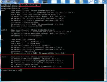
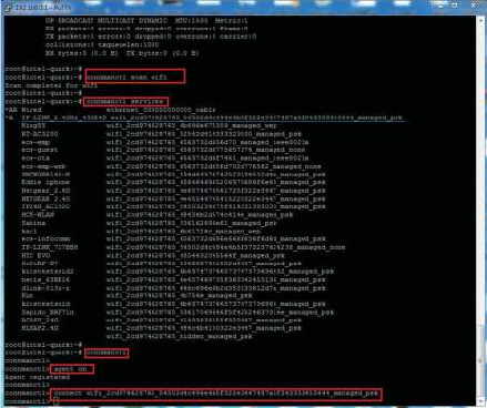
WiFi網路設定
步驟1.檢查網路介面。
-
步驟2.
-
- connmanctl services
- connmanctl
- agent on
-
30
31
Bluetooth設定連結
依照下列command輸入
Sendshellcommand.
(連接)
- bluetoothctl
- agent on
- power on
- scan on
- scan off
- devices
- pair BT MAC Address
- trust BT MAC Address
(中斷)
- disconnect BT MAC Address
- remove BT MAC Address
32
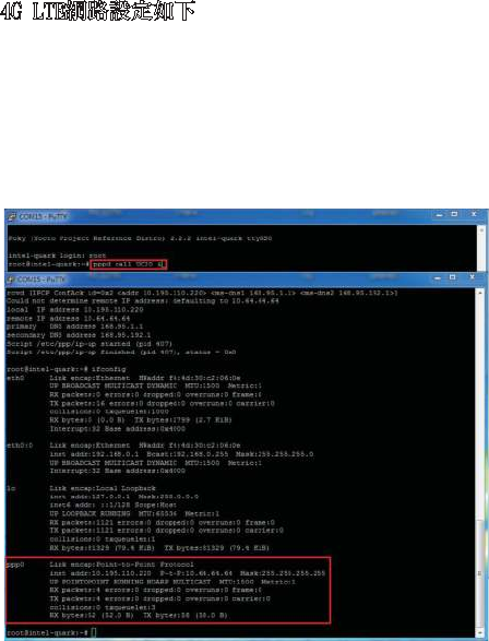
4G LTE網路設定如下
I依照下列command輸入
(依照使用的LTEmodule選擇1-3其中之一command)
- 1.
2. pppd call UC20 & --> QuecTel UC21-JMINPCIE
3. pppd call UC20 & --> QuecTel EC21-AU
-
33
程式範例
在GWS-HZW1板子上,大部分的GPIO功能都可以透過Linux
Sysfs介面來動作,而且可以用檔案I/O的方式來進行控
制。以下將介紹如何通過簡易的shell命令使用其中的某
些功能。當然除了shell,您可以使用程式以檔案操作方
式來執行I/O,這些程式可以用您最喜歡的程式語言進行
編寫。
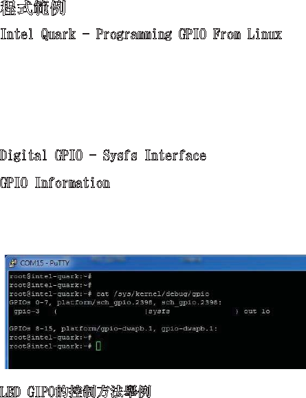
Intel Quark - Programming GPIO From Linux
以下命令給出了有關系統中GPIO的資訊,且顯示了一個IO
埠被分配給哪一個Module或Sysfs(使用者)。
Command : cat /sys/kernel/debug/gpio
GPIO Information
Digital GPIO - Sysfs Interface
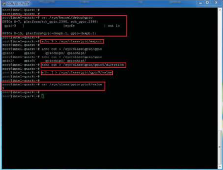
LED GIPO的控制方法舉例
- 設定GPIO腳位
- 設定GPIO為input或output
34
- 設定GPIO開關
- 查詢GIPO目前的值

35
Operating temperature: 0
℃~
45
℃
(32
℉~
113
℉)
Storage Temperature: -20
℃~
60
℃
(-4
℉~
140
℉
)
Danger of explosion if battery is incorrectly replaced.
Replace only with the same or equivalent type
recommended by the manufacturer. Dispose of
used batteries according to the manufacturer’s
instructions.
此為非手持式裝置帶電池式產品,符合SAR的相關規定
(1)此裝置不得導致有害干擾;以及(2)此裝置必須接受
任何干擾,包括可能會導致非預期操作的干擾。
注意事項
本產品工作溫度:0℃~45℃(32℉~113℉)
存儲溫度:-20℃~60℃(-4℉~140℉)
如果電池更換不當會有爆炸危險。請僅更換相同型
號或製造商推薦的同類型號的電池。請根據製造商
的說明處置廢舊電池。

36
本產品符合低功率電波輻射性電機管理辦法第十二條、
第十四條等條文規定。
1.經型式認證合格之低功率射頻電機,非經許可,公
司、商號或使用者均不得擅自變更頻率、加大功率或
變更原設計之特性及功能。
2.低功率射頻電機之使用不得影響飛航安全及干擾合法
通信;經發現有干擾現象時,應立即停用,並改善至
無干擾時方得繼續使用。前項合法通信,指依電信法
規定作業之無線電通信。
低功率射頻電機須忍受合法通信或工業、科學及醫療用電
波輻射性電機設備之干擾。
CCAO18LP0020T8
This device complies with Part 15 of the FCC Rules.
Operation is subject to the following two conditions:
(1) This device may not cause harmful interference
(2) This device must accept any interference
received, including interference that may cause
undersired opreation
To assure continued FCC compliance:
approved by the grantee of this device could void
the user’s authority to operate the equipment.
2. This equipment complies with FCC radiation
exposure limits set forth for an uncontrolled
environment. This equipment should be installed and
operated with minimum distance 20cm between
the radiator & your body.

37
單元
限用物質及其化學符號
鉛
(Pb)
汞
(Hg)
鎘
(Cd)
六價鉻
(Cr+6)
多溴聯苯
(PBB)
多溴二
苯醚
(PBDE)
電路板(卡) - ○ ○ ○ ○ ○
電子紙顯示
器模組 ○ ○ ○ ○ ○ ○
塑膠機構件 - ○ ○ ○ ○ ○
金屬機構件 - ○ ○ ○ ○ ○
線材 ○ ○ ○ ○ ○ ○
電源供應器 - ○ ○ ○ ○ ○
備考1.〝○〞係指該項限用物質之百分比含量未超出百分比含量
基準值。
備考2.〝-〞係指該項限用物質為排除項目。
限用物質含有情況標示

進口/委製造商
Elitegroup Computer Systems Co., LTD.
精英電腦股份有限公司
台北市內湖區堤頂大道二段239號
+886-2-21621177