ELITEGROUP COMPUTER SYSTEMS SKM-U-MPCH Personal Computer User Manual Preface pmd
ELITEGROUP COMPUTER SYSTEMS CO., LTD Personal Computer Preface pmd
User Manual
i
SKM-U mPC
Copyright
This publication, including all photographs, illustrations and software, is protected under interna-
tional copyright laws, with all rights reserved. Neither this manual, nor any of the material con-
tained herein, may be reproduced without written consent of the author.
Version 2.0
Disclaimer
The information in this document is subject to change without notice. The manufacturer makes no
representations or warranties with respect to the contents hereof and specifically disclaims any
implied warranties of merchantability or fitness for any particular purpose. The manufacturer
reserves the right to revise this publication and to make changes from time to time in the content
hereof without obligation of the manufacturer to notify any person of such revision or changes.
Trademark Recognition
Microsoft, MS-DOS and Windows are registered trademarks of Microsoft Corp. MMX, Pentium,
Pentium-II, Pentium-III, Celeron are registered trademarks of IntelCorporation. Other product names
used in this manual are the properties of their respective owners and are acknowledged.
Regulatory Compliance Information
FCC Declaration of Conformity
This device complies with Part 15 of the FCC Rules. Operation is subject to the following two
conditions:
(1) this device may not cause harmful interference, and (2) this device must accept any interfer-
ence received, including interference that may cause undesired operation.
This equipment has been tested and found to comply with the limits for a Class B digital device,
pursuant to part 15 of the FCC Rules. These limits are designed to provide reasonable protection
against harmful interference in a residential installation. This equipment generates, uses, and
can radiate radio frequency energy and, if not installed and used in accordance with the instruc-
tions, may cause harmful interference to radio communications. However, there is no guarantee
that interference will not occur in a particular installation. If this equipment does cause harmful
interference to radio or television reception, which can be determined by turning the equipment
off and on, the user is encouraged to try to correct the interference by one or more of the following
measures:
Reorient or relocate the receiving antenna.
Increase the separation between the equipment and receiver.
Connect the equipment into an outlet on a circuit different form that to which the receiver is
connected.
Consult the dealer or an experienced radio/TV technician for help.
This equipment complies with FCC radiation exposure limits set forth for an uncontrolled environ-
ment. This equipment should be installed and operated with minimum distance 20 cm between
the radiator and your body.
This device meets the government¡ ¯s requirements for exposure to radio waves.
This device is designed and manufactured not to exceed the emission limits for exposure to radio
frequency (RF) energy set by the Federal Communications Commission of the U.S. Government,
Industry Canada, and other national regulatory agencies.

ii
SKM-U mPC
Any special accessories needed for compliance must be specified in the instruction manual. Use
only shielded and terminated cables to connect I/O devices to this equipment.
Warning! Any changes or modications made to the equipment which are not expressly
approved by the relevent standards authority could void your authority to
operate the equipment.
本產品符合低功率電波輻射性管理辦法 第十二條、第十四條等條文
規定
1. 經型式認證合格之低功率射頻電機,非經許可,公司、商號或使用
者均不得擅自變更頻率、加大功率或變更原
設計之特性及功能。
2. 低功率射頻電機之使用不得影響飛航安全及干擾合法通信;經發現
有干擾現象時,應立即停用,並改善至無干
擾時方得繼續使用。 前項合法通信,指依電信法規定作業之無線電
通信。 低功率射頻電機須忍受合法通信或工業、
科學及醫療用電波輻射性電機設備之干擾。
MPE
Exposure to Radio Frequency Radiation:
To comply with FCC RF exposure compliance requirements, a separation distance of at least 20cm
must be maintained between the antenna of this device and all persons. This device must not be
co-located or operating conjunction with any other antenna or transmitter.
CE, FCC, NCC RF
USA RF: FCC Caution
This equipment complies with FCC radiation exposure limits set forth for an uncontrolled environ-
ment. This equipment should be installed and operated with minimum distance 20cm between
the radiator & your body.
Canada RF: IC Caution
This equipment complies with IC radiation exposure limits set forth for an uncontrolled environ-
ment. This equipment should be installed and operated with minimum distance 20cm between
the radiator & your body.
Cet équipement est conforme aux limites d’exposition aux
rayonnements IC établies pour un environnement non
contrôlé. Cet équipement doit être installé et utilisé avec un
minimum de 20 cm de distance entre la source de
rayonnement et votre corps.
Taiwan RF: NCC Caution
Attention!
Tout changement ou modification n
on expressément approuvé par
l'autorité compétente peut annuler le droit du propriétaire à utiliser
l'équipement
iii
SKM-U mPC
Japan VCCI Statement
CE mark. Declaring compliance to all the applicable European Union (EU) Directives.
Waste disposal instruction
Do not throw this electronic device into the trash can when discard-
ing. Tominimize pollution and ensure utmost protection of the global
environment, please recycle it in European WEEE (waste electrical
and electronic equipment) directive system or recycle system in Tai-
wan.
Part NO. Edition 2
Printed in China AUG 2016
電磁波曝露量 MPE 標準值 1mW/cm2,送測產品實測值為:
0.0941mW/cm2
®

iv
SKM-U mPC
Packing List
Before setting up the system, check that the items listed below are included and in good condi-
tion. If any items are missing, please contact your dealer immediately.
SKM-U mPC x1
Adapter 65W / 90W x1 (Optional)
User Manual x1
Antenna x2 (Optional)
VESA Mount Bracket x1 (Optional)
Warning!
Attention!
To prevent electric shock, Do not remove cover.
No user serviceable parts inside, refer servicing to qualified personnel.
Warning!
Additional Information and Assistance
1. Visit the ECS websites at www.ECS.com.tw where you can find the latest information about the
product.
2. Contact your distributor, sales representative, or ECS’s customer service center for technical
support if you need additional assistance. Please have the following information ready before
you call:
- Product name and serial number
- Description of your peripheral attachments
- Description of your software (operating system, version, application software, etc.)
- A complete description of the problem
- The exact wording of any error messages
- This equipment is a source of electromagnetic waves. Before use, please make sure that
there are not EMI sensitive devices in its surrounding which may malfunction therefore
1. Input voltage rated 100-240V~, 50~60Hz, 1.5A max
Output Voltage rated 3.43A, 19Vdc
2. Input voltage rated 100-240V~, 50~60Hz, 1.5A max
Output Voltage rated 4.74A, 19Vdc
3. Maintenance: to properly maintain and clean the surfaces, use only
approved products or clean with a dry applicator
Pour éviter un choc électrique, ne pas retirer le couvercle.
Aucune pièce réparable par l'utilisateur, voir l'entretien à du personnel
qualifié.
Extension HDD Box x1 (Optional)
Extension COM Box x1 (Optional)
Micro B to Type A Cable x1 (Optional)
DB44 to DB9 Cable x1 (Optional)
Attention!
1. Le voltage d'entrée nominale de 100-240V~, 50-60Hz. Max à 1.5A
Le voltage de sortie nominal 3.43A, 19Vdc
2. Le voltage d'entrée nominale de 100-240V~, 50-60Hz. Max à 1.5A
Le voltage de sortie nominal 3.74A, 19Vdc
3. La maintenance :
Entretenez et nettoyez les surfaces avec soin, Utiliser
seulement les produits ratifiés ou nettoyer avec un applicateur sec

v
SKM-U mPC
Warning! Danger of explosion if battery is incorrectly replaced.
Replace only with the same or equivalent type recommended by the manufac-
turer.
Dispose of used batteries according to the manufacturer’s instructions.
Prudence!
Danger d'explosion si la pile est remplacée de façon incorrecte.
Remplacez-la exclusivement par une batterie identique ou par
un type de batterie équivalent recommandé par le fabricant
La mise au rebut des batteries usagées doit se faire conformément aux
indications du fabricant de ces batteries.
vi
SKM-U mPC
1. Read these safety instructions carefully.
2. Keep this User Manual for later reference.
3. Disconnect this equipment from any AC outlet before cleaning. Use a damp cloth.
Do not use liquid or spray detergents for cleaning.
4. For plug-in equipment, the power outlet socket must be located near the equipment and must
be easily accessible.
5. Keep this equipment away from humidity.
6. Put this equipment on a reliable surface during installation. Dropping it or letting it fall may
cause damage.
7. The openings on the enclosure are for air convection. Protect the equipment from overheating.
DO NOT COVER THE OPENINGS.
8. Make sure the voltage of the power source is correct before connecting the equipment to the
power outlet.
9. Position the power cord so that people cannot step on it. Do not place anything over the power
cord.
10. All cautions and warning on the equipment should be noted.
11. If the equipment is not used for a longt time, discounnect it from the power source to avoid
damage by transient overvoltage.
12. Never pour any liquid into an opening. This may cause fire or electrical shock.
13. Never open the equipment. For safety reasons, the equipment should be opened only by
qualified service personnel.
14. If one of the following situations arises, get the equipment checked by service personnel:
a. The power cord or plug is damaged.
b. Liquid has penetrated into the equipment.
c. The equipment has been exposed to moisture.
d. The equipment does not work well, or you cannot get it to work according to the user¡ ¯s
manual.
e. The equipment has been dropped and damaged.
f. The equipment has obvious signs of breakage.
15. DO NOT LEAVE THIS EQUIPMENT IN AN ENVIRONMENT WHERE THE STORAGE TMPERATURE
MAY GO BELOW -20° C (-4° F) OR ABOVE 60°C (140° F). THIS COULD DAMAGE THE EQUIP-
MENT. THE EQUIPMENT SHOULD BE IN A CONTROLLED ENVIRONMENT.
16. If your computer is losing time significantly or the BIOS configuration resets itself to be
default, the battery may have no power.
17. IMPROPER INSALLATION OF VESA MOUNTING CAN RESULT IN SERIOUS PERSONAL INJURY!
VESA mount installation should be performed by a professional technician; please contact
the service technician or your retailer if you need this service.
18. Maintenace: to properly maintain and clean the surfaces, use only the approved products or
clean with a dry applicator.
Safety Instructions
vii
SKM-U mPC
Contents
Chapter 1 System Information........................................................................................................1
1.1 Introduction.................................................................................................................1
1.2 Specifications..............................................................................................................2
1.3 Claeaning/Disinfecting.................................................................................................4
Chapter 2 Getting Started.............................................................................................................5
2.1 System Tour................................................................................................................5
Figure 2.1 Top View........................................................................................5
Figure 2.2 Bottom View...................................................................................5
Figure 2.3 Bottom View..................................................................................5
Figure 2.4 I/O Side View.................................................................................6
2.2 Distribution Description...............................................................................................8
2.3 Powering the System...................................................................................................8
Chapter 3 Hardware Installation...................................................................................................9
3.1 Motherboard Introduction...........................................................................................9
3.2 Installing the Motherboard.........................................................................................12
Chapter 4 Using BIOS...............................................................................................................21
4.1 About the Setup Utility...............................................................................................21
4.2 Using BIOS..............................................................................................................22
Chapter 5 Feature Information....................................................................................................49
5.1 Introduction..............................................................................................................49
viii
SKM-U mPC
MEMO

1
SKM-U mPC
Chapter 1
System Information
1.1 Introduction
The product has onboard Intel® SkylakeTM U SoC for pesonal micro desktop markets or educational
usage.
Below is a brief summary of the computer’s many features:
NOTE:
The features listed in this section is for your reference only. The exact configuration of the system depends on
the model purchased.

2
SKM-U mPC
1.2 Specifications
CPU/SoC Intel® SkyLake™ U SOC
Super I/O IT8607
Dimension 101.6*104*1.6mm
Channel/DIMM type 2 channels/DDR4 2133
Socket numbers/type 2 sockets/SO‐DIMM Slot
MEM size Max 32GB
M.2 SSD 1x2280, for SSD(SATA interface) Key M
SATA 6GB/s 1xSATA connector, for 2.5"/HDD(customized)
M.2 WLAN Intel/3165NGW
AUDIO chip Realtek ALC283‐CG
LAN chip Realtek RTL8111H
USB 3.1 Type‐A1
USB 3.1 Type‐C1
IR 1
Audio 1x UAJ(Combo jack)
HDMI 1x A type HDMI, support 4K/2K
DP 1x mini DP, support 4K/2K
LAN 1x LAN connector, Gigabit LAN
USB 3.0 2x USB 3.0 ports
1x DC jack,(base on power consumption)
19V 3.43A(65W)
19V 4.74A(90W)
DC Jack
MEMORY
STORAGE
Additional Feature
Chip
Front Port I/O
Rear I/O
Description
CPU
Super I/O
PCB Dimension
System Dimension
116.6*112*64.6mm(w/HDD)
116.6*112*64.6mm(w/o HDD)
Dimension

3
SKM-U mPC
CPU FAN 1 (H4x1, 4pins, P=1.25mm)
Serial SATA III 1x SATA connector, for 2.5" HDD
SATA PWR 1 (H5x1, 5pins, P=1.25mm)
Battery connector 1 (H2x1, 2pins, P=1.25mm)
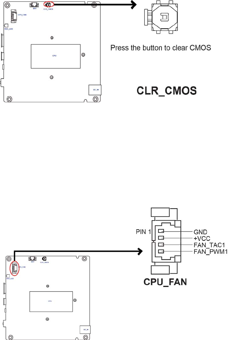
CLR CMOS 1 (SWITCH.TACT, 2P 180D.H1.5mm)
Power ON LED 1 (SMD, Color.blue)
LOGO LED header 1 (H2x1, P=2.0mm, P=1.25mm)
Wireless charger header (Not Support) (H2x1, 2pins, P=1.25mm)
Speaker (Optional) (H4x1, 4pins, P=0.8mm)
NFC header (Optional) (H8x1, 8pins, p=05.mm)
HDD LED 1 (SMD, Color.Green)
Power button 1 (Design by RD)
OS Windows 10
BIOS 64 Mb SPI ROM
FSP ADAPTER/FSP065‐10AABA
19Vdc, 3.43A.65W
APD ADAPTER/WA‐65B19R
19Vdc, 3.43A.65W
APD ADAPTER/DA‐90F19
19Vdc, 4.74A.90W
INTERNAL I/O CONNECTORS & HEADERS
FPC header
2 (Type design by EE, USB 3.0 signal
FPC Header for Pogo Pin
Top: 14 Pin FPC to 10 Pogo Pin
Bottom: 16 Pin FPC to 10 Pogo Pin
SYSTEM
Description
Adapter

4
SKM-U mPC
Caution!
1.3 Cleaning/Disinfecting
During normal use SKM-U mPC may become solied and should, therefore, be cleaned regularly.
Steps:
1. Wipe SKM-U mPC with a clean cloth that has been moistened in the cleaning solution.
2. Prepare agent per manufacturer’s instructions or hospital protocol.
3. Wipe thoroughly with a clean cloth.
Do not immerse or rinse SKM-U mPC or its peripherals. If you accidentally spill liquid
on the device, disconnect the unit from the power source. Contact your Biomed per-
sonnel regarding the continued safety of the unit before placing it back in operation.
Do not spray cleaning agent on the chassis.
Do not use disinfectants that contain phenol.
Do not autoclave or clean SKM-U mPC or its peripherals with strong aromatic, chlori-
nated, ketone, ether, or other solvents, sharp tools or abrasives. Never immerse elec-
trical connectors in water or other liquids.
Attention!
Ne pas immerger ou rincer SKM-U mPC ou ses périphériques. Si vous
renversez par accident un liquide sur l'appareil, débranchez l'appareil de
la source d'alimentation. Contactez votre Biomed concernant la sécurité
continue de l'unité avant de la remettre en service.
Ne pas pulvériser l'agent de nettoyage sur le châssis.
Ne pas utiliser de désinfectants contenant du phénol.
Ne pas passer à l'autoclave ou SKM-U
mPC propre ou ses périphériques
avec fortes, cétone, éther, ou d'autres solvants, des outils tranchants ou
abrasifs aromatiques chlorés. Ne jamais plonger connecteurs électriques
dans l'eau ou d'autres liquids.
5
SKM-U mPC
Chapter 2
Getting Started
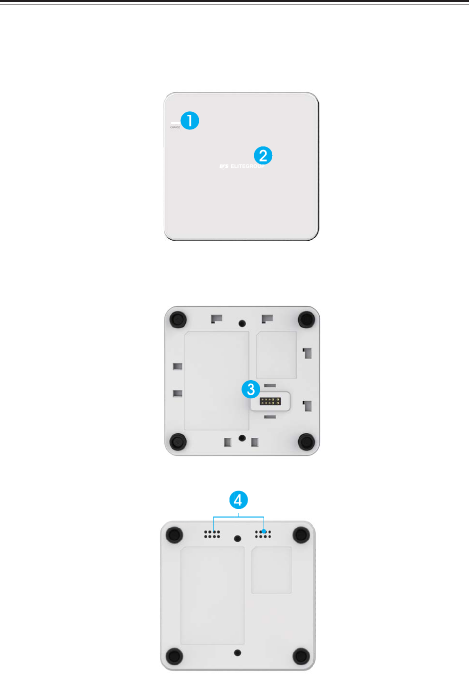
2.1 System Tour
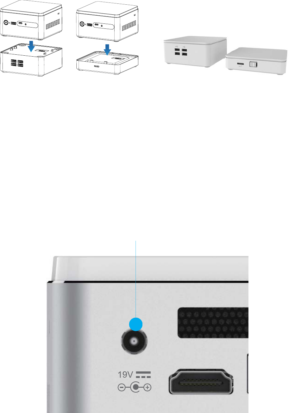
Before you start to set up system, take a moment to become familiar with the location sand
purposes of the controls, drives, connections and ports, which are illustrated in the figures below.
Figure 2.1 Top View
Figure 2.2 Bottom View
Figure 2.3 Bottom View
6
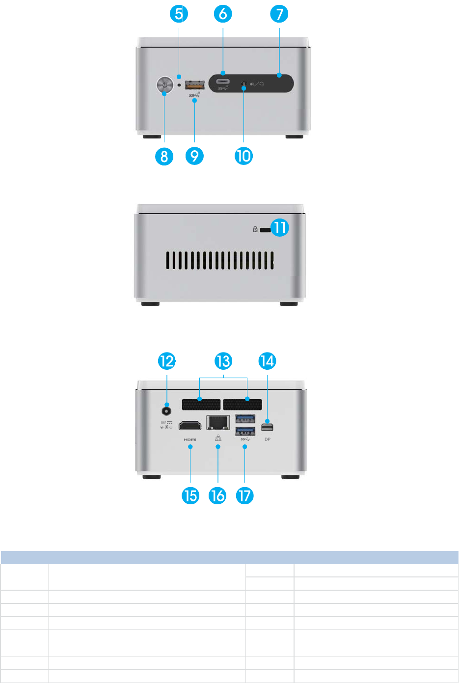
SKM-U mPC
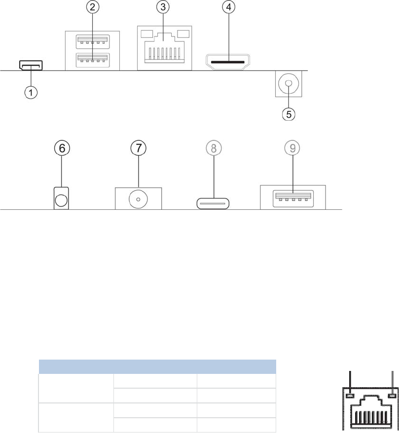
No Components No Components
9 USB 3.1 (TypeA / BC1.2)
10 Combo Audio Jack (Mic In & Line Out)
2 Wireless Charger / LED (Optional) 11 Kensington Lock
3 Pogo Pin (Optional) 12 DC Jack
4 Speaker (Optional) 13 Thermal Opening
5 HDD LED 14 DP
6 USB 3.1 (Type C) 15 HDMI
7 IR Sensor 16 RJ45 Port
8 Power Button 17 USB3.0
1Wireless Charger LED (Optional)
(Power Transfer Green Blink, Fault Red Blink)
Figure 2.4 IO Side View
Figure 2.5 Side View
Figure 2.6 IO Side View
7
SKM-U mPC
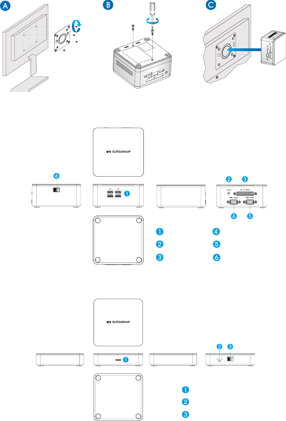
Install the VESA Mount
Extension COM Box (Optional)
Extension HDD Box (Optional)
HDD LENS
Micro USB 3.0
Latch
USB 2.0
DC Jack
DB-44 / RS232
COM Port RS422
COM Port RS485
Latch
8
SKM-U mPC
2.2 Distribution Description
The operating system is based on Windows 10 64bit / FreeDOS.
2.3 Distribution Description
Connecting a 19V adapter to the DC-In Jack, the system will start up automatically.
DC-In
Assembly-COM Box / HDD Box
COM Box
HDD
9
SKM-U mPC
Chapter 3
Hardware Installation
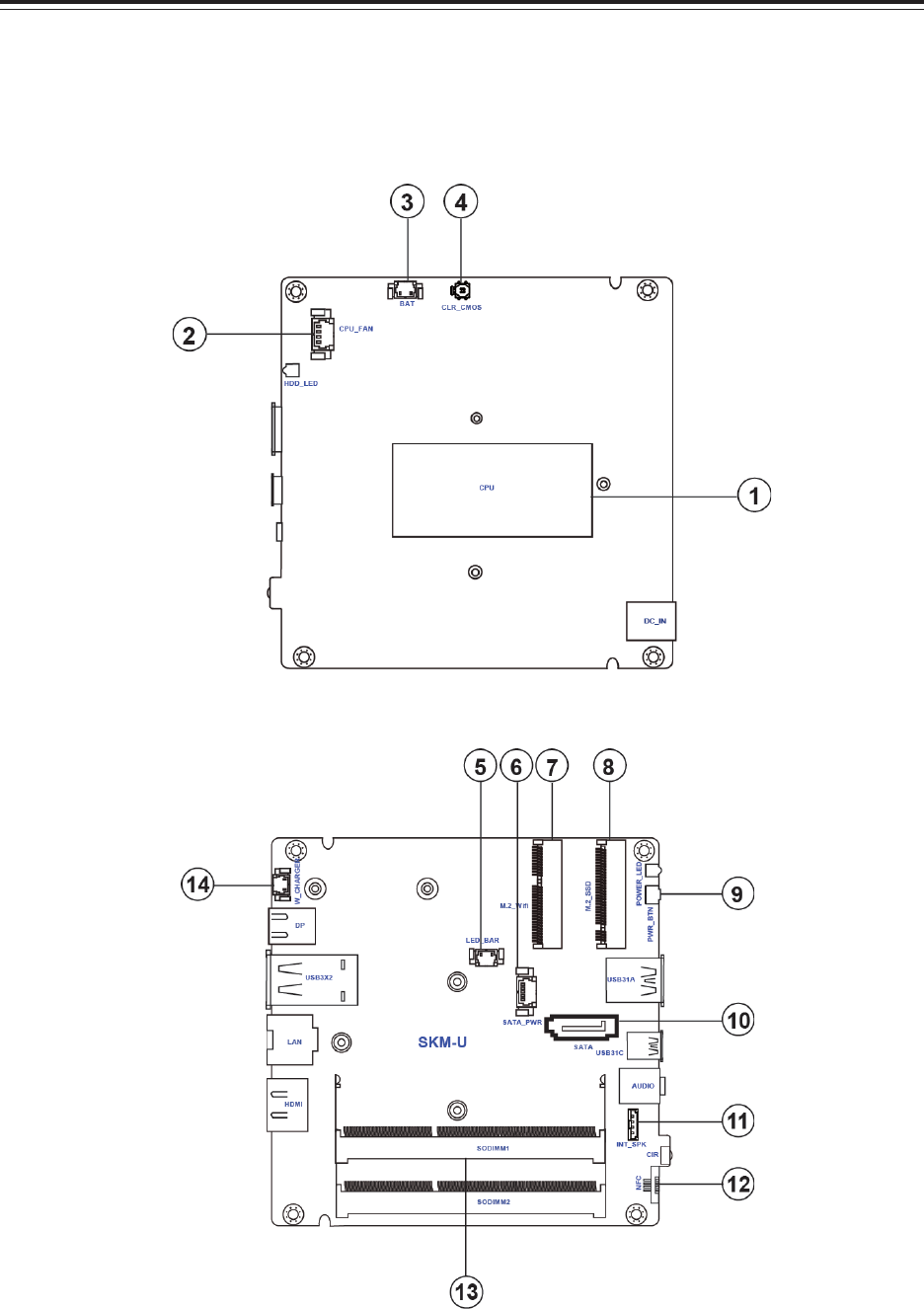
3.1 Motherboard introduction
Before you start to set up system, take a moment to become familiar with the location sand
purposes of the controls, drives, connections and ports, which are illustrated in the figures below.

10
SKM-U mPC
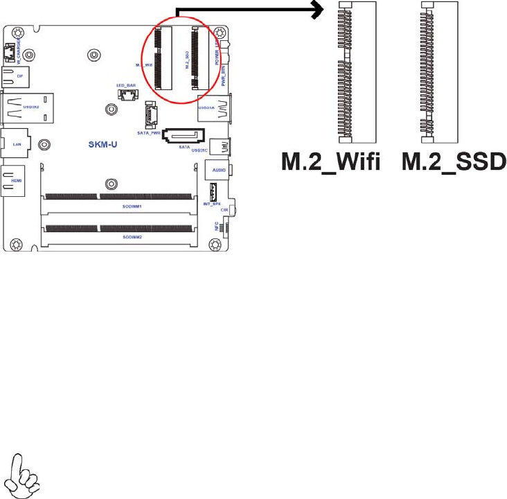
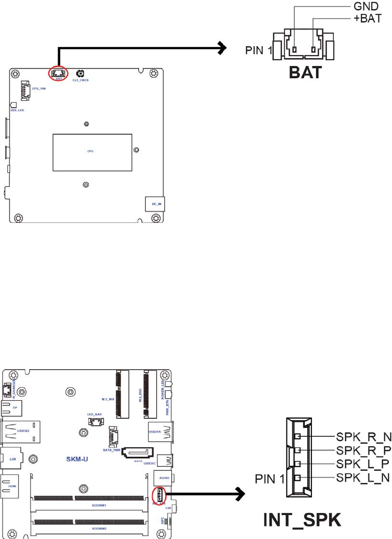
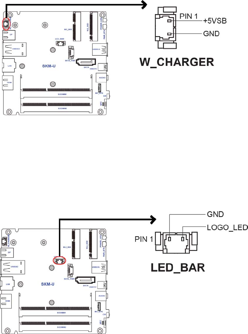
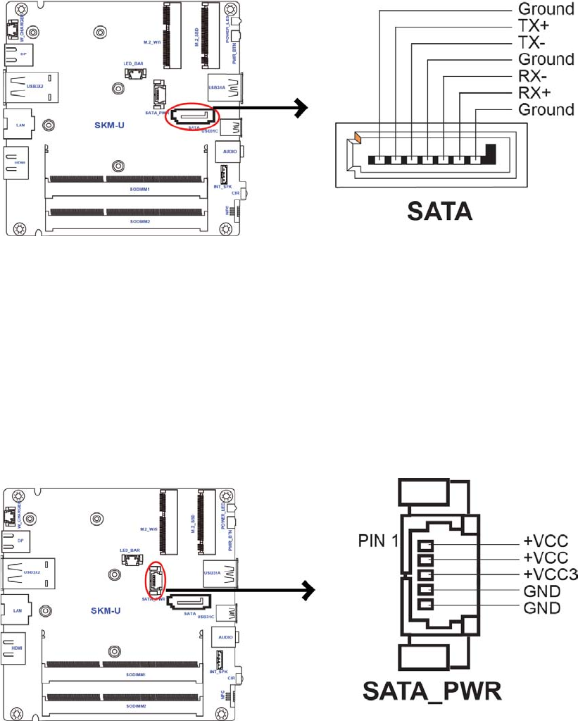
Table of Motherboard Components
LABEL COMPONENTS
1.CPU Intel® SkyLake™ U SOC
2.CPU_FAN CPU cooling fan connector
3.BAT Battery connector
4.CLR_CMOS Clear CMOS jumper
5.LED_BAR Logo LED connector
6.SATA_PWR SATA power connector
7.M.2_Wifi M.2 slot for Wifi
8.M.2_SSD M.2 slot for SSD
9.PWR_BTN Power button
10.SATA Serial ATA connector
11.INT_SPK Internal Speaker connector
12.NFC NFC connector
13.SODIMM1~2 DDR4 2133 SO-DIMM slots
14.W_CHARGER Wireless charger connector
11
SKM-U mPC
I/O Ports
1. DP Port
Connect the display devices to the DP port.
2. USB 3.0 Ports
Use the USB 3.0 ports to connect USB 3.0 devices.
3. RJ45 LAN Port
Connect an RJ-45 jack to the LAN port to connect your computer to the Network.
4. HDMI Port
Connect the display devices to the HDMI port.
5. DC 19V Jack
Connect the DC_IN jack to the power adapter.
6. CIR
It is customer IR sensor.
7. Combo Audio Jack (Mic In & Line Out)
Use the combo audio jack to connect the microphone, speaker or headphone.
8. USB 3.1 (Type-C) Port
Use the USB 3.1 (Type-C) port to connect USB 3.1 devices.
9. USB 3.1 Port
Use the USB 3.1 ports to connect USB 3.1 devices.
LAN LED Status Description
OFF No data
Orange blinking Active
OFF No link
Green Link
Activity LED
Link LED
Activity LED Link LED
12
SKM-U mPC
3.2 Installing the Motherboard
Before you start to set up system, take a moment to become familiar with the location sand
purposes of the controls, drives, connections and ports, which are illustrated in the figures below.
1. Safety Precautions
Follow these safety precautions when installing the motherboard:
• Wear a grounding strap attached to a grounded device to avoid damage from static elec-
tricity.
• Discharge static electricity by touching the metal case of a safely grounded object before
working on the motherboard.
• Leave components in the static-proof bags.
• Always remove the AC power by unplugging the power cord from the power outlet before
installing or removing the motherboard or other hardware components.
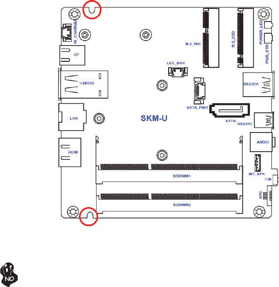
2. Installing the motherboard in a Chassis
• Aim four locating holes of the SKM-U motherboard.
• Use four screws to secure the motherboard.
Do not over-tighten the screws as this can stress the motherboard.
13
SKM-U mPC
3. Installing Hardware
• This motherboard accommodates two memory module. It can support two 204-pin DDR4
DIMM 2133 MHz.
• Do not remove any memory module from its antistatic packaging until you are ready to
install it on the motherboard. Handle the modules only by their edges. Do not touch the
components or metal parts. Always wear a grounding strap when you handle the modules.
• You must install one module in the slot. Total memory capacity is 32 GB.
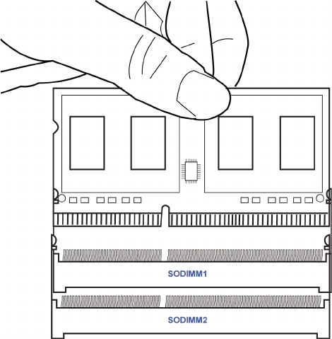
• Refer to the following to install the memory modules.
Install the DIMM module into the slot and press it firmly down until it fits in place. Check that the
cutouts on the DIMM module edge connector match the notches in the DIMM slot.
3-1. Installing Memory Modules
14
SKM-U mPC
3-2. Installing Add-on Cards
The slots on this motherboard are designed to hold expansion cards and connect them to the
system bus. Expansion slots are a means of adding or enhancing the motherboard’s features and
capabilities. With these efficient facilities, you can increase the motherboard’s capabilities by
adding hardware that performs tasks that are not part of the basic system.
M.2_Wifi Slot The M.2 slot is for extending usage which supports half-card with Wifi signal.
Before installing an add-on card, check the documentation for the card care-
fully. If the card is not Plug and Play, you may have to manually configure the
card before installation.
M.2_SSD Slot The M.2 slot is for extending usage which supports half-card with SSD signal.
15
SKM-U mPC
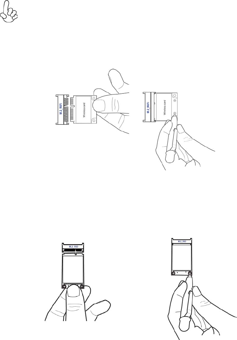
1 Remove a blanking plate from the system case corresponding to the slot you are going to
use.
2 Install the edge connector of the add-on card into the expansion slot. Ensure that the edge
connector is correctly seated in the slot.
3 Secure the metal bracket of the card to the system case with a screw.
Follow these instructions to install an add-on card:
Please refer to the following illustrations to install the add-on card:
* For reference only
Insert a WIFI card into the M.2_Wifi Slot.
For some add-on cards, for example graphics adapters and network adapters, you have
to install drivers and software before you can begin using the add-on card.
Insert a SSD card into the M.2_SSD Slot.
* For reference only
16
SKM-U mPC
3-3. Checking Jumper Settings
This section explains how to set jumpers for connecting configuration of the motherboard.
1. CPU_FAN: CPU cooling fan connector
Connect the CPU cooling fan to the CPU_FAN connector.
Refer to the following for information on connecting the motherboard’s devices.
3-4. Connecting Optional Devices.
17
SKM-U mPC
2. BAT: Battery connector
2. INT_SPK: Internal Speaker connector
18
SKM-U mPC
4. W_CHARGER: Wireless charger connector
5. LED_BAR: Logo LED connector
19
SKM-U mPC
6. SATA: Serial ATA connector
7. SATA_PWR: SATA power connector

20
SKM-U mPC
8. NFC: NFC connector

21
SKM-U mPC
Chapter 4
Using BIOS
About the Setup Utility
The computer uses the latest “American Megatrends Inc. ?BIOS with support for Windows Plug
and Play. The CMOS chip on the motherboard contains the ROM setup instructions for configuring
the motherboard BIOS.
The BIOS (Basic Input and Output System) Setup Utility displays the system’s configuration status
and provides you with options to set system parameters. The parameters are stored in battery-
backed-up CMOS RAM that saves this information when the power is turned off. When the system
is turned back on, the system is configured with the values you stored in CMOS.
The BIOS Setup Utility enables you to configure:
The settings made in the Setup Utility affect how the computer performs. Before using the Setup
Utility, ensure that you understand the Setup Utility options.
This chapter provides explanations for Setup Utility options.
• Hard drives, diskette drives and peripherals
• Video display type and display options
• Password protection from unauthorized use
• Power Management features
The Standard Configuration
A standard configuration has already been set in the Setup Utility. However, we recommend that
you read this chapter in case you need to make any changes in the future. This Setup Utility should
be used:
• when changing the system configuration
• when a configuration error is detected and you are prompted to make changes to the
Setup Utility
• when trying to resolve IRQ conflicts
• when making changes to the Power Management configuration
• when changing the password or making other changes to the Security Setup
Entering the Setup Utility
When you power on the system, BIOS enters the Power-On Self Test (POST) routines. POST is a
series of built-in diagnostics performed by the BIOS. After the POST routines are completed, the
following message appears:
Press DEL to enter SETUP

22
SKM-U mPC
Aptio Setup Utility - Copyright (C) 2016 American Megatrends, Inc.
Main Advanced Chipset Tweak Security Boot Exit
BIOS Information
System Date [Tue 08/02/2016]
System Time [14:44:26]
Version 2.17.1255. Copyright (C) 2016 American Megatrends, Inc.
Set the Date. Use Tab to
switch between Data elements.
: Select Screen
: General Help
: Change Opt.
Enter : Select
: Select Item
: Previous Values
: Optimized Defaults
: Save & Exit
ESC : Exit
+/-
F1
F2
F3
F4
Press the delete key to access BIOS Setup Utility.
Using BIOS
When you start the Setup Utility, the main menu appears. The main menu of the Setup Utility
displays a list of the options that are available. A highlight indicates which option is currently
selected. Use the cursor arrow keys to move the highlight to other options. When an option is
highlighted, execute the option by pressing <Enter>.
Some options lead to pop-up dialog boxes that prompt you to verify that you wish to execute that
option. Other options lead to dialog boxes that prompt you for information.
Some options (marked with a triangle
)lead to submenus that enable you to change the values
for the option. Use the cursor arrow keys to scroll through the items in the submenu.
In this manual, default values are enclosed in parenthesis. Submenu items are denoted by a tri-
angle
.
The default BIOS setting for this motherboard apply for most conditions with optimum
performance. We do not suggest users change the default values in the BIOS setup
and take no responsibility to any damage caused by changing the BIOS settings.
23
SKM-U mPC
For the purpose of better product maintenance, the manufacture reserves the right to
change the BIOS items presented in this manual. The BIOS setup screens shown in
this chapter are for reference only and may differ from the actual BIOS. Please visit
the manufacture’s website for updated manual.
KEY FUNCTION
Scrolls through the items on a menu
+/-
F2 Previous Value
F3 Optimized Defaults
F1 General Help
ESC
Enter Select
F4 Save & Exit
Exits the current menu
Change Opt.
BIOS Navigation Keys
The BIOS navigation keys are listed below:

24
SKM-U mPC
Aptio Setup Utility - Copyright (C) 2016 American Megatrends, Inc.
Main Advanced Chipset Tweak Security Boot Exit
BIOS Information
System Date [Tue 08/02/2016]
System Time [14:44:26]
Version 2.17.1255. Copyright (C) 2016 American Megatrends, Inc.
Set the Date. Use Tab to
switch between Data elements.
: Select Screen
: General Help
: Change Opt.
Enter : Select
: Select Item
: Previous Values
: Optimized Defaults
: Save & Exit
ESC : Exit
+/-
F1
F2
F3
F4
Main Menu
When you enter the BIOS Setup program, the main menu appears, giving you an overview of the
basic system information. Select an item and press <Enter> to display the submenu.
System Date & Time
The Date and Time items show the current date and time on the computer. If you are running a
Windows OS, these items are automatically updated whenever you make changes to the Windows
Date and Time Properties utility.

25
SKM-U mPC
Aptio Setup Utility - Copyright (C) 2016 American Megatrends, Inc.
Main Advanced Chipset Tweak Security Boot Exit
LAN Configuration
PC Health Status
Power Management Setup
ACPI Settings
CPU Configuration
SATA Configuration
USB Configuration
Super IO Configuration
Trusted Computing
Version 2.17.1255. Copyright (C) 2016 American Megatrends, Inc.
LAN Configuration Parameters
: Select Screen
: General Help
: Change Opt.
Enter : Select
: Select Item
: Previous Values
: Optimized Defaults
: Save & Exit
ESC : Exit
+/-
F1
F2
F3
F4
Advanced Menu
This page sets up more advanced information about your system. Handle this page with caution.
Any changes can affect the operation of your computer.
26
SKM-U mPC
LAN Configuration
The item in the menu shows the LAN-related information that the BIOS automatically detects.
Aptio Setup Utility - Copyright (C) 2016 American Megatrends, Inc.
Advanced
LAN Configuration
Onboard LAN Controller [Enabled]
Version 2.17.1255. Copyright (C) 2016 American Megatrends, Inc.
Enabled / Disabled Onboard LAN
Controller
: Select Screen
: General Help
: Change Opt.
Enter : Select
: Select Item
: Previous Values
: Optimized Defaults
: Save & Exit
ESC : Exit
+/-
F1
F2
F3
F4
Onboard LAN Controller (Enabled)
Use this item to enble or disable the Onboard LAN.
Press <Esc> to return to the Advanced Menu page.

27
SKM-U mPC
PC Health Status
On motherboards support hardware monitoring, this item lets you monitor the parameters for
critical voltages, temperatures and fan speeds.
Aptio Setup Utility - Copyright (C) 2016 American Megatrends, Inc.
Advanced
PC Health Status
Smart Fan Function
CPU Temperature (DTS) 75
System Temperature 53O C
CPU Fan Speed 2789 RPM
Core Voltage 0.780V
DIMM Voltage 1.212V
+5V 5.040V
+3.3V 3.264V
+19V 19.080V
TCC Activation Temperature (DTS) 100
Version 2.17.1255. Copyright (C) 2016 American Megatrends, Inc.
Enabled / Disabled Onboard LAN
Controller
: Select Screen
: General Help
: Change Opt.
Enter : Select
: Select Item
: Previous Values
: Optimized Defaults
: Save & Exit
ESC : Exit
+/-
F1
F2
F3
F4
Smart Fan Function
Scroll to this item and press <Enter> to view the following screen:
Aptio Setup Utility - Copyright (C) 2016 American Megatrends, Inc.
Advanced
Smart Fan Select [CPU]
Smart Fan Mode [Normal]
Smart Fan start PWM value 89
Smart Fan start PWM TEMP (DTS) 76
Deltat 2
Smart Fan Slope PWM value 6
Fan Full Speed Offset (DTS) 91
Version 2.17.1255. Copyright (C) 2016 American Megatrends, Inc.
Enabled / Disabled Onboard LAN
Controller
: Select Screen
: General Help
: Change Opt.
Enter : Select
: Select Item
: Previous Values
: Optimized Defaults
: Save & Exit
ESC : Exit
+/-
F1
F2
F3
F4

28
SKM-U mPC
Smart Fan Select (CPU)
This item enables you to select CPU Smart fan or System Smart fan, and control it.
Smart Fan Mode (Normal)
This item allows you to select the fan mode (Normal, Quiet, Silent, or Manual) for a better opera-
tion environment. If you choose Normal mode, the fan speed will be auto adjusted depending on
the CPU temperature. If you choose Quite mode, the fan speed will be auto minimized for quiet
environment. If you choose Silent mode, the fan speed will be auto restricted to make system
more quietly. If you choose Manual mode, the fan speed will be adjust depending on users’ p
parameters.
Smart Fan start PWM value (89)
This item is used to set the start PWM value of the smart fan.
Smart Fan start PWM TEMP (DTS) (76)
This item is used to set the start temperature of the smart fan.
DeltaT (2)
This item specifies the range that controls CPU temperature and keeps it from going so high or so
low when smart fan works.
Smart Fan Slope PWM value (6)
This item is used to set the Slope Select PWM of the smart fan.
Fan Full Speed Offset (DTS) (91)
This item is used to set the CPU fan/System fan full speed offset value.
• CPU Temperature
• System Temperature
• CPU Fan Speed
• Core Voltage
• DIMM Voltage
• +5V
• +3.3V
• +19V
System Component Characteristics
These items display the monitoring of the overall inboard hardware health events, such as System
temperature, CPU & DIMM voltage, CPU & System fan speed... etc.
Press <Esc> to return to the PC Health Status page.
Press <Esc> to return to the Advanced Menu page.

29
SKM-U mPC
Power Management Setup
This page sets up some parameters for system power management operation.
Aptio Setup Utility - Copyright (C) 2016 American Megatrends, Inc.
Advanced
Power Management Setup
Resume By PME [Disabled]
Resume By USB [Disabled]
Resume By CIR [Disabled]
Resume By RTC Alarm [Disabled]
EUP Function [Enabled]
Version 2.17.1255. Copyright (C) 2016 American Megatrends, Inc.
About Resume By
PCI / PCI-E / LAN / Ext. USB3.1 PME
: Select Screen
: General Help
: Change Opt.
Enter : Select
: Select Item
: Previous Values
: Optimized Defaults
: Save & Exit
ESC : Exit
+/-
F1
F2
F3
F4
Resume By PME (Disabled)
This item specify whether the system will be awakened from power saving modes when activity or
input signal of the specified hardware peripheral or components is detected.
EUP Function (Enabled)
This item allows user to enable or disable EUP support.
Resume By USB (Disabled)
This item allows you to enable/disable the USB device wakeup function from S3 mode.
Resume By RTC Alarm (Disabled)
The system can be turned off with a software command. If you enable this item, the system can
automatically resume at a fixed time based on the system’s RTC (realtime clock). Use the items
below this one to set the date and time of the wake-up alarm. You must use an ATX power supply
in order to use this feature.
Resume By CIR (Disabled)
This item enables or disables you to wake up the system by IR.
Press <Esc> to return to the Advanced Menu page.
30
SKM-U mPC
ACPI Settings
This item in the menu shows the highest ACPI sleep state when system enters suspend.
Aptio Setup Utility - Copyright (C) 2016 American Megatrends, Inc.
Advanced
ACPI Settings
ACPI Sleep State [S3 (Suspend to RAM)]
Version 2.17.1255. Copyright (C) 2016 American Megatrends, Inc.
Select the highest ACPI sleep
state the system will enter
when the SUSPEND button is
pressed.
: Select Screen
: General Help
: Change Opt.
Enter : Select
: Select Item
: Previous Values
: Optimized Defaults
: Save & Exit
ESC : Exit
+/-
F1
F2
F3
F4
ACPI Sleep State (S3 (Suspend to RAM))
This item allows you to enter the ACPI S3 (Suspend to RAM) Sleep State (default).
Press <Esc> to return to the Advanced Menu page.

31
SKM-U mPC
CPU Configuration
This item in the menu shows the CPU Configuration.
Aptio Setup Utility - Copyright (C) 2016 American Megatrends, Inc.
Advanced
CPU Configuration
Intel (R) Core (TM) i5-6260U CPU @ 1.80GHz
EM64T Supported
Processor Speed 1800 MHz
Processor Stepping 406E3
Microcode Revision 8A
Processor Cores 2
Intel HT Technology Supported
Intel VT-x Technology Supported
Hyper-threading [Enabled]
Active Processor Cores [All]
Limit CPUID Maximum [Disabled]
Execute Disable Bit [Enabled]
Intel Virtualization Technology [Enabled]
Package C State limit [AUTO]
Enhanced Halt (C1E) [Enabled]
Version 2.17.1255. Copyright (C) 2016 American Megatrends, Inc.
Enabled for windows XP and
Linnux (OS optimaized for
Hyper-Threading Technology)
and Disabled for other OS (OS
not optimaized for
Hyper-Threading Technolofy).
when Disabled only one thraead
per enabled core is enabled.
: Select Screen
: General Help
: Change Opt.
Enter : Select
: Select Item
: Previous Values
: Optimized Defaults
: Save & Exit
ESC : Exit
+/-
F1
F2
F3
F4
Processor Speed (1800 MHz)
This item shows the processor speed.
EM64T (Supported)
This item shows the computer supports EMT64.
Processor Stepping (406E3)
This item shows the processor stepping version.
Intel (R) Core (TM) i5-6260U CPU @ 1.80GHz
This is display-only field and displays the informaton of the CPU installed in your computer.
Microcode Revision (8A)
This item shows the Microcode version.
Processor Cores (2)
This item shows the number of cores of the processor.
Intel HT Technology (Supported)
This item shows the computer supports Intel HT technology or not.
Intel VT-x Technology (Supported)
This item shows the computer supports Intel VT-x technology or not.
Hyper-threading (Enabled)
This item only available when the chipset supports Hyper-threading and you are using a Hyper-
threading CPU.
Active Processor Cores (All)
Use this item to control the number of active processor cores.

32
SKM-U mPC
Excute Disable Bit (Enabled)
This item allows the processor to classify areas in memory by where application code can execute
and where it cannot. When a malicious worm attempts to insert code in the buffer, the processor
disables code execution, preventing damage or worm propagation. Replacing older computers
with Execute Disable Bit enabled systems can halt worm attacks, reducing the need for virus
related repair.
Limit CPUID Maximum (Disabled)
Use this item to enable or disable the maximum CPUID value limit, you can enable this item to
prevent the system from “rebooting” when trying to install Windows NT 4.0.
Intel Virtualization Technology (Enabled)
When disabled, a VMM cannot utilize the additional hardware capabilities provided by Vandor
Pool Technology.
Enhanced Halt (ClE) (Enabled)
Use this item to enable the CPU energy-saving function when the system is not running.
Package C state limit (AUTO)
Use this item to set package C state limit.
Press <Esc> to return to the Advanced Menu page.

33
SKM-U mPC
ACPI Settings
This item in the menu shows the highest ACPI sleep state when system enters suspend.
Aptio Setup Utility - Copyright (C) 2016 American Megatrends, Inc.
Advanced
SATA Configuration
SATA Controller (s) [Enabled]
SATA Mode [AHCI]
SATA Port1
Not Present
M.2
TS128GMTS800 (128.0GB)
Version 2.17.1255. Copyright (C) 2016 American Megatrends, Inc.
Enable or disable the SATA Contrller
: Select Screen
: General Help
: Change Opt.
Enter : Select
: Select Item
: Previous Values
: Optimized Defaults
: Save & Exit
ESC : Exit
+/-
F1
F2
F3
F4
SATA Controllers (Enabled)
This item allows you to to enable or disable SATA controllers.
SATA Mode (AHCI)
Use this item to select SATA mode.
SATA Port1 (Not Present/M.2)
This motherboard supports one SATA channel and one M.2_SSD, each channel allows one SATA
device to be installed. Use these items to configure each device on the SATA channel and the
M.2_SSD.
Press <Esc> to return to the Advanced Menu page.

34
SKM-U mPC
USB Configuration
Use this item to show the information of USB configuration.
Aptio Setup Utility - Copyright (C) 2016 American Megatrends, Inc.
Advanced
USB Configuration
All USB Devices [Enabled]
Legacy USB Support [Enabled]
USB3.0 Controller [Enabled]
Version 2.17.1255. Copyright (C) 2016 American Megatrends, Inc.
USB Support Parameters
: Select Screen
: General Help
: Change Opt.
Enter : Select
: Select Item
: Previous Values
: Optimized Defaults
: Save & Exit
ESC : Exit
+/-
F1
F2
F3
F4
All USB Devices (Enabled)
Use this item to enable or disable all USB devices
Legacy USB Support (Enabled)
Use this item to enable or disable support for legacy USB devices.
USB3.1 Contrller (Enabled)
Use this item to enable or disable USB3.1 contrller.
Press <Esc> to return to the Advanced Menu page.

35
SKM-U mPC
Super IO Configuration
Use this item to show the information of Super IO configuration.
Aptio Setup Utility - Copyright (C) 2016 American Megatrends, Inc.
Advanced
Super IO Configuration
Super IO Chip IT8607
NFC Port Configuration
CIR Controller Configuration
Version 2.17.1255. Copyright (C) 2016 American Megatrends, Inc.
Set Parameters of NFC Port
: Select Screen
: General Help
: Change Opt.
Enter : Select
: Select Item
: Previous Values
: Optimized Defaults
: Save & Exit
ESC : Exit
+/-
F1
F2
F3
F4
Super IO Chip (IT8607)
This item shows the information of the super IO chip.
36
SKM-U mPC
NFC Port Configuration
Scroll to this item and press <Enter> to view the following screen.
Aptio Setup Utility - Copyright (C) 2016 American Megatrends, Inc.
Advanced
NFC Port Configuration
NFC Port [Enabled]
Device Settings IO-3F8h; IRQ=4;
Change Settings [Auto]
Version 2.17.1255. Copyright (C) 2016 American Megatrends, Inc.
Enabled or disabled NFC Port
: Select Screen
: General Help
: Change Opt.
Enter : Select
: Select Item
: Previous Values
: Optimized Defaults
: Save & Exit
ESC : Exit
+/-
F1
F2
F3
F4
NFC Port (Enabled)
This item allows you to enable or disable NFC.
Device Settings (IO=3F8h; IRQ=4;)
This item shows the information of the device settings.
Change Settings (Auto)
Use this item to change device settings.
Press <Esc> to return to the Advanced Menu page.
Press <Esc> to return to the Super IO Configuration page.
37
SKM-U mPC
CIR Controller Configuration
Scroll to this item and press <Enter> to view the following screen.
Aptio Setup Utility - Copyright (C) 2016 American Megatrends, Inc.
Advanced
CIR Controller Configuration
CIR Controller [Enabled]
Device Settings IO-3E0h; IRQ=10;
Change Settings [Auto]
Version 2.17.1255. Copyright (C) 2016 American Megatrends, Inc.
Enabled or disabled CIR
Controller
: Select Screen
: General Help
: Change Opt.
Enter : Select
: Select Item
: Previous Values
: Optimized Defaults
: Save & Exit
ESC : Exit
+/-
F1
F2
F3
F4
CIR Controller (Enabled)
This item allows you to enable or disable CIR Controller.
Device Settings (IO=3E0h; IRQ=10;)
This item shows the information of the device settings.
Change Settings (Auto)
Use this item to change device settings.
Press <Esc> to return to the Advanced Menu page.
Press <Esc> to return to the Super IO Configuration page.

38
SKM-U mPC
Trusted Computing
Use this item to show the information of trusted computing configuration.
Aptio Setup Utility - Copyright (C) 2016 American Megatrends, Inc.
Advanced
TPM20 Device Found
TPM Support [Enabled]
TPM State [Enabled]
HashPolicy [Sha-1]
Version 2.17.1255. Copyright (C) 2016 American Megatrends, Inc.
Enabled or disabled BIOS
support for security device.
O.S. will not show Security
Device. TCG EFI protocol and
INDIA interface will not be
available.
: Select Screen
: General Help
: Change Opt.
Enter : Select
: Select Item
: Previous Values
: Optimized Defaults
: Save & Exit
ESC : Exit
+/-
F1
F2
F3
F4
TPM Support (Enabled)
Use this item to enable or disable the TPM support. OS will nor show TPM. Reset of platform is
required.
TPM State (Enabled)
Use this item to enable or disable the security device.
HashPolicy (Sha-1)
Select the Hash policy to use. SHA-2 is most secure but might not be supported by all Operating
Systems.
Press <Esc> to return to the Advanced Menu page.

39
SKM-U mPC
Aptio Setup Utility - Copyright (C) 2016 American Megatrends, Inc.
Main Advanced Chipset Tweak Security Boot Exit
System Agent Configuration
PCH Configuration
ME Configuration
Version 2.17.1255. Copyright (C) 2016 American Megatrends, Inc.
LAN Configuration Parameters
: Select Screen
: General Help
: Change Opt.
Enter : Select
: Select Item
: Previous Values
: Optimized Defaults
: Save & Exit
ESC : Exit
+/-
F1
F2
F3
F4
Chipset Menu
This page sets up more advanced information about your system. Handle this page with caution.
Any changes can affect the operation of your computer.
40
SKM-U mPC
System Agent Configuration
Scroll to this item and press <Enter> and view the following screen:
Press <Esc> to return to the Chipset Menu page.
Aptio Setup Utility - Copyright (C) 2016 American Megatrends, Inc.
Chipset
System Agent Configuration
IGD Memory [64M]
DVMT Memory [256M]
Version 2.17.1255. Copyright (C) 2016 American Megatrends, Inc.
Select DVMT 5.0 Pre-Allocated
(Fixed) Graphics Memory size
used by the Internal Graphics
Device.
: Select Screen
: General Help
: Change Opt.
Enter : Select
: Select Item
: Previous Values
: Optimized Defaults
: Save & Exit
ESC : Exit
+/-
F1
F2
F3
F4
IGD Memory (64M)
This item shows the information of the IGD (Internal Graphics Device) memory.
DVMT Memory (256M)
When set to Fixed Mode, the graphics driver will reserve a fixed positon of the system memory as
graphics memory, according to system and graphics equirements.
41
SKM-U mPC
PCH Configuration
Scroll to this item and press <Enter> and view the following screen:
Press <Esc> to return to the Chipset Menu page.
Aptio Setup Utility - Copyright (C) 2016 American Megatrends, Inc.
Chipset
PCH Configuration
Restore AC Power Loss [Power Off]
Audio Configuration
Azalia HD Audio [Enabled]
Version 2.17.1255. Copyright (C) 2016 American Megatrends, Inc.
Select DVMT 5.0 Pre-Allocated
(Fixed) Graphics Memory size
used by the Internal Graphics
Device.
: Select Screen
: General Help
: Change Opt.
Enter : Select
: Select Item
: Previous Values
: Optimized Defaults
: Save & Exit
ESC : Exit
+/-
F1
F2
F3
F4
Restore AC Power Loss (Power Off)
This item enables your computer to automatically restart or return to its operating status.
Azalia HD Audio (Enabled)
This item enables or disables Azalia HD audio.

42
SKM-U mPC
ME Configuration
Scroll to this item and press <Enter> and view the following screen:
Press <Esc> to return to the Chipset Menu page.
Aptio Setup Utility - Copyright (C) 2016 American Megatrends, Inc.
Chipset
Management Engine Technology Configuration
ME Control [Enabled]
ME FW Version 11.0.0.1202
Version 2.17.1255. Copyright (C) 2016 American Megatrends, Inc.
Enable/Disable ME Firmware
: Select Screen
: General Help
: Change Opt.
Enter : Select
: Select Item
: Previous Values
: Optimized Defaults
: Save & Exit
ESC : Exit
+/-
F1
F2
F3
F4
ME Control (Enabled)
Use this item to enable or disable the ME Firmware.
ME FW Version (9.1.0.1120)
This item shows the ME FW version.

43
SKM-U mPC
Aptio Setup Utility - Copyright (C) 2016 American Megatrends, Inc.
Main Advanced Chipset Tweak Security Boot Exit
Tweak
Turbo Boost [Enabled]
Intel (R) Core (TM) i5-6260U CPU @ 1.80GHz
Processor Speed 1800 MHz
Memory Frequency 2133 MHz
Total Memory 4096 MB
Version 2.17.1255. Copyright (C) 2016 American Megatrends, Inc.
Turbo Boost
: Select Screen
: General Help
: Change Opt.
Enter : Select
: Select Item
: Previous Values
: Optimized Defaults
: Save & Exit
ESC : Exit
+/-
F1
F2
F3
F4
Tweak Menu
This page enables you to monitor or set some information of the processor you have installed in
your system.
Turbo Boost (Enabled)
This item allows you to enable or disable the turbo boost.
Intel(R) Core (TM) i5-6260U CPU @ 1.80GHz
This is display-only field and displays the information of the CPU installed in your computer.
Total Memory (4096 MB)
This item shows the total memory.
Processor Speed (1800 MHz)
This item shows the current CPU speed.
Memory Frequency (2133 MHz)
This item shows the memory frequency.

44
SKM-U mPC
Aptio Setup Utility - Copyright (C) 2016 American Megatrends, Inc.
Main Advanced Chipset Tweak Security Boot Exit
Administrator Password
Administrator Password Not Install
User Password Status Not Install
System Mode state Setup
Secure Boot state Not Active
Secure Boot [Enabled]
Secure Boot Mode [Standard]
Version 2.17.1255. Copyright (C) 2016 American Megatrends, Inc.
Set Adiministrator Password
: Select Screen
: General Help
: Change Opt.
Enter : Select
: Select Item
: Previous Values
: Optimized Defaults
: Save & Exit
ESC : Exit
+/-
F1
F2
F3
F4
Security Menu
This page enables you to set administrator password and user password.
Administrator Password Status (Installed)
This item shows administrator password installed or not.
User Password Status (Not Installed)
This item shows user password installed or not.
System Mode state (Setup)
This item shows system mode setup or not.
Secure Boot state (Not Active)
This item allows you to enable or disable the secure boot state.
Secure Boot (Enabled)
This item is used to control the secure boot flow, it is possible only if system runs in User Mode.
Secure Boot Mode (Standard)
This item is used to select secure booe mode, when you select standard mode, secure boot policy
is fixed; when you select custom mode, the image execution policy and secure boot key datebases
are changeable.

45
SKM-U mPC
Aptio Setup Utility - Copyright (C) 2016 American Megatrends, Inc.
Main Advanced Chipset Tweak Security Boot Exit
Boot Configuration
Operating System Select [Windows 8.x / 10]
Launch PXE OpROM [Disabled]
Launch Storage OpROM [Enabled]
Bootup MumLock State [On]
Quiet Boot [Enabled]
Boot Mode Select [UEFI]
Fixed BOOT ORDER Priorities
Boot Option #1 [Hard Disk: windows B...]
Boot Option #2 [USB Hard Disk]
Boot Option #3 [USB CD/DVD]
Boot Option #4 [USB Key]
Boot Option #5 [USB Floppy]
Boot Option #6 [Network]
UEFI Hard Disk Drive Priorities
Version 2.17.1255. Copyright (C) 2016 American Megatrends, Inc.
Windows 7 or other OS: Boot
policy for Legacy OS
Windows 8.x / 10: Boot policy
for UEFI OS without
Compatibility Support
Module (CSM)
Manual: User cusomiazed CSM
parameters & boot policy
: Select Screen
: General Help
: Change Opt.
Enter : Select
: Select Item
: Previous Values
: Optimized Defaults
: Save & Exit
ESC : Exit
+/-
F1
F2
F3
F4
Boot Menu
This page enables you to set the keyboard NumLock state.
UEFI Hard Disk Drive Priorities
This item enables you to specify the sequence of loading the operating system from the installing
Hard Disk drive.(This item only shows when there is boot device connecting)
Press <Enter> to see the submenu.
Operating System Select (Windows 8.x / 10)
This item is used to select the operating system.
Launch PXE OpROM (Disabled)
This item enables or disables launch PXE Option ROM
Launch Storage OpROM (Enabled)
This item enables or disables the Storage OpROM.
Bootup NumLock State (On)
This item enables you select NumLock state.
Quiet Boot (Enabled)
This item enables or disables the boot LOGO.
Boot Mode Select (UEFI)
Use this item to select boot mode.
Boot Option #1~6 (UEFI)
These items show the boot priorities and can be used to set the boot priorities of various device
categories.

46
SKM-U mPC
Aptio Setup Utility - Copyright (C) 2016 American Megatrends, Inc.
Main Advanced Chipset Tweak Security Boot Exit
Save Changes and Exit
Discard Changes and Exit
Save Changes and Reset
Discard Changes and Reset
Save Options
Save Changes
Discard Changes
Restore Defaults
Save as User Defaults
Restore as User Defaults
Boot Override
Windows Boot Manager (P1: TS128GMTS800)
Version 2.17.1255. Copyright (C) 2016 American Megatrends, Inc.
Exit system setup after saving
the changes.
: Select Screen
: General Help
: Change Opt.
Enter : Select
: Select Item
: Previous Values
: Optimized Defaults
: Save & Exit
ESC : Exit
+/-
F1
F2
F3
F4
Exit Menu
This page enables you to set administrator password and user password.
Save Options
This item enables you to save the options that you have made.
Save Changes
This item enables you to save the changes that you have made.
Discard Changes
This item enables you to discard any changes that you have made.
Restore Defaults
This item enables you to restore the system defaults.
Save Changes and Exit
This item enables you to exit system setup after saving the changes.
Discard Changes and Exit
This item enables you to exit system setup without saving any changes.
Discard Changes and Reset
This item enables you to reset system setup without saving any changes.
Save as User Defaults
This item enables you to save the changes that you have made as user defaults.
Restore User Defaults
This item enables you to restore the user defaults.
Save Changes and Reset
This item enables you to reset system setup after saving the changes.
Boot Override
Use this item to select the boot device.
47
SKM-U mPC
1 If your motherboard has a BIOS protection jumper, change the setting to allow BIOS
flashing.
2 If your motherboard has an item called Firmware Write Protect in Advanced BIOS fea-
tures, disable it. (Firmware Write Protect prevents BIOS from being overwritten.)
3 Prepare a bootable device or create a bootable system disk. (Refer to Windows online
help for information on creating a bootable system disk.)
4 Download the Flash Utility and new BIOS file from the manufacturer’s Web site. Copy
these files to the bootable device.
5 Turn off your computer and insert the bootable device in your computer. (You might need
to run the Setup Utility and change the boot priority items on the Advanced BIOS Fea-
tures Setup page, to force your computer to boot from the bootable device first.)
6 At the C:\ or A:\ prompt, type the Flash Utility program name and the file name of the
new BIOS and then press <Enter>. Example: AFUDOS.EXE 040706.ROM
7 When the installation is complete, remove the bootable device from the computer and
restart your computer. If your motherboard has a Flash BIOS jumper, reset the jumper to
protect the newly installed BIOS from being overwritten. The computer will restart
automatically.
Updating the BIOS
You can download and install updated BIOS for this motherboard from the manufacturer’s Website.
New BIOS provides support for new peripherals, improvements in performance, or fixes for known
bugs. Install new BIOS as follows:
48
SKM-U mPC
Memo
49
SKM-U mPC
Chapter 5
Feature Information
Introduction
The NFC and wireless charger is optional feature on this computer. Please refer to following in-
structions.
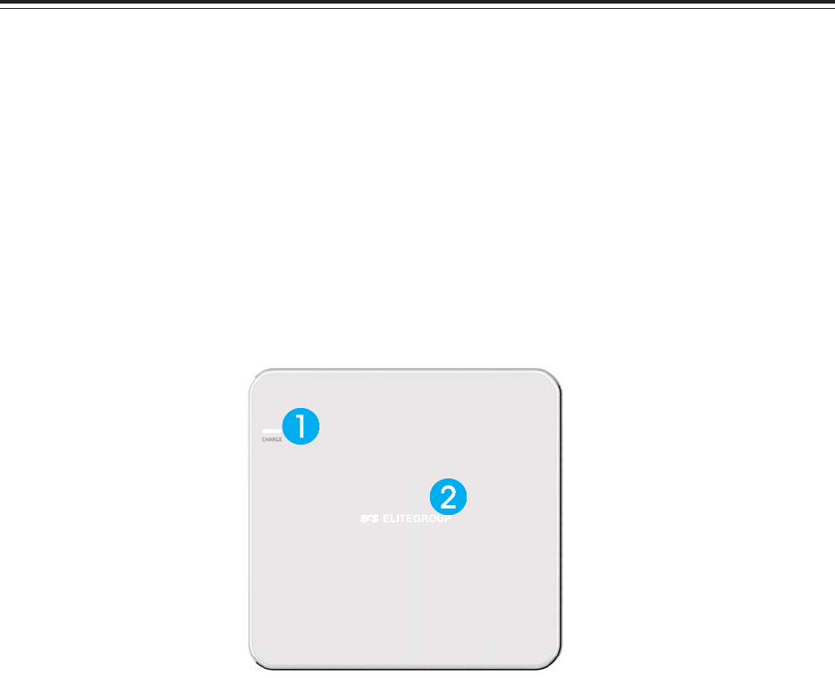
1. Wireless charger
The Wireless charger specification that the computer support is compatible with Qi. Put the Rx
device on charger area for power tranfer.
2. NFC
The NFC module that compatible with (1) ISO 15693 (2) ISO 14443A (3) ISO 14443B. Put the device
on the center of computer for read/write.
50
SKM-U mPC
MEMO