ELITEGROUP COMPUTER SYSTEMS SKM-U-MPCM Personal Computer User Manual Preface pmd
ELITEGROUP COMPUTER SYSTEMS CO., LTD Personal Computer Preface pmd
UserManual.wiki
>
ELITEGROUP COMPUTER SYSTEMS
>
SKM U MPCM User Manual
User Manual
Navigation menu
Upload a User Manual
Namespaces
Wiki Guide
HTML
PDF
Info
Views
User Manual
Discussion / Help
Navigation


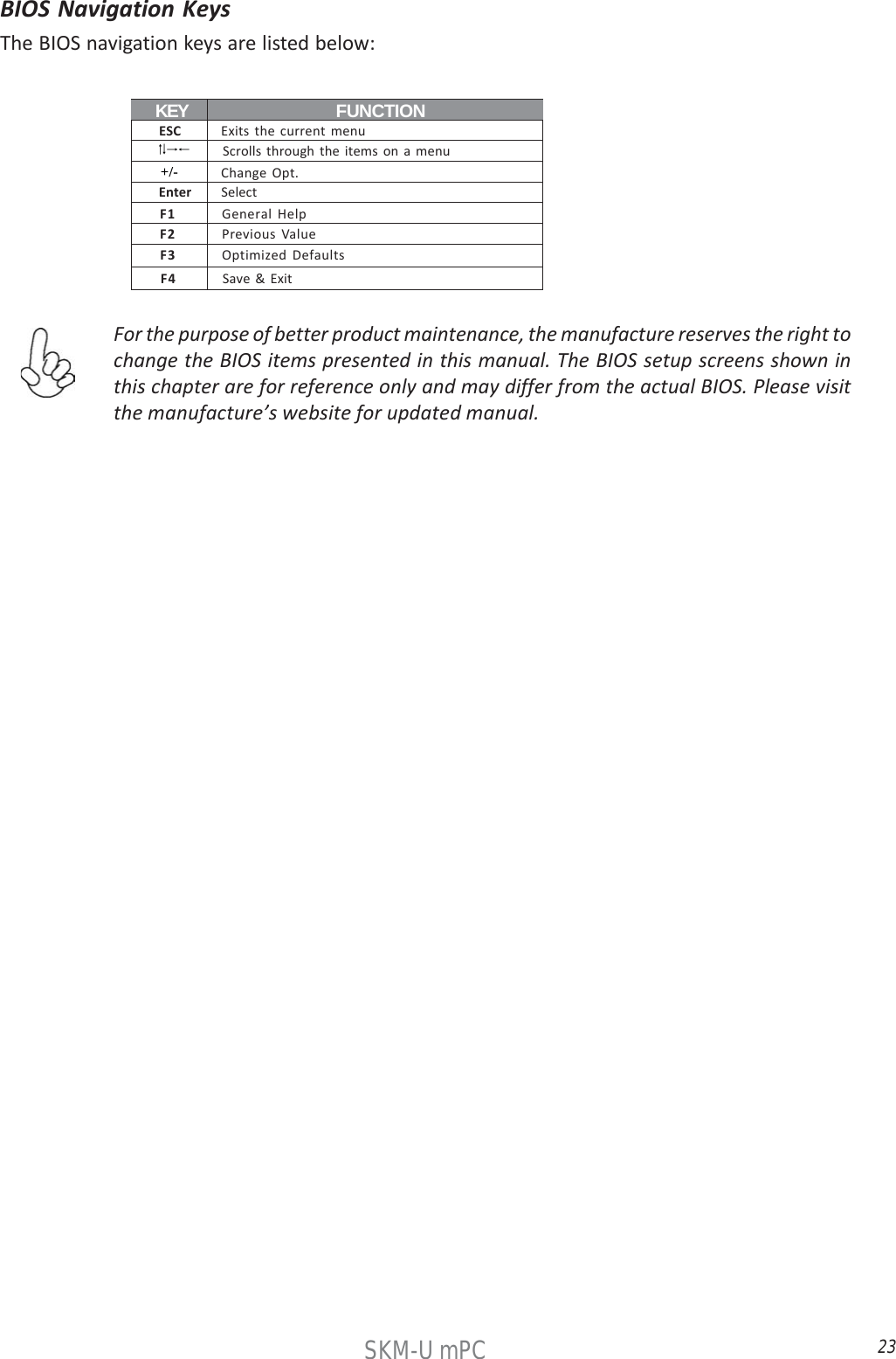
![22SKM-U mPCAptio Setup Utility - Copyright (C) 2016 American Megatrends, Inc. Main Advanced Chipset Tweak Security Boot ExitBIOS InformationSystem Date [Tue 08/02/2016]System Time [14:44:26] Version 2.17.1255. Copyright (C) 2016 American Megatrends, Inc.Set the Date. Use Tab toswitch between Data elements. : Select Screen : General Help : Change Opt.Enter : Select : Select Item : Previous Values : Optimized Defaults : Save & ExitESC : Exit+/-F1F2F3F4Press the delete key to access BIOS Setup Utility.Using BIOSWhen you start the Setup Utility, the main menu appears. The main menu of the Setup Utilitydisplays a list of the options that are available. A highlight indicates which option is currentlyselected. Use the cursor arrow keys to move the highlight to other options. When an option ishighlighted, execute the option by pressing <Enter>.Some options lead to pop-up dialog boxes that prompt you to verify that you wish to execute thatoption. Other options lead to dialog boxes that prompt you for information.Some options (marked with a triangle )lead to submenus that enable you to change the valuesfor the option. Use the cursor arrow keys to scroll through the items in the submenu.In this manual, default values are enclosed in parenthesis. Submenu items are denoted by a tri-angle .The default BIOS setting for this motherboard apply for most conditions with optimumperformance. We do not suggest users change the default values in the BIOS setupand take no responsibility to any damage caused by changing the BIOS settings.](https://usermanual.wiki/ELITEGROUP-COMPUTER-SYSTEMS/SKM-U-MPCM/User-Guide-3171951-Page-30.png)
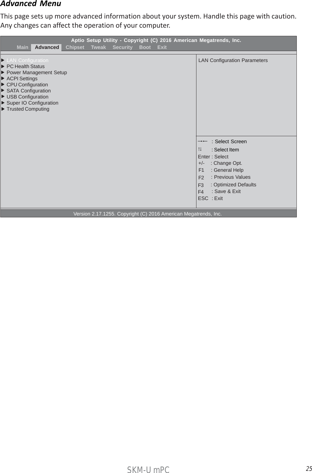
![24SKM-U mPCAptio Setup Utility - Copyright (C) 2016 American Megatrends, Inc. Main Advanced Chipset Tweak Security Boot ExitBIOS InformationSystem Date [Tue 08/02/2016]System Time [14:44:26] Version 2.17.1255. Copyright (C) 2016 American Megatrends, Inc.Set the Date. Use Tab toswitch between Data elements. : Select Screen : General Help : Change Opt.Enter : Select : Select Item : Previous Values : Optimized Defaults : Save & ExitESC : Exit+/-F1F2F3F4Main MenuWhen you enter the BIOS Setup program, the main menu appears, giving you an overview of thebasic system information. Select an item and press <Enter> to display the submenu.System Date & TimeThe Date and Time items show the current date and time on the computer. If you are running aWindows OS, these items are automatically updated whenever you make changes to the WindowsDate and Time Properties utility.](https://usermanual.wiki/ELITEGROUP-COMPUTER-SYSTEMS/SKM-U-MPCM/User-Guide-3171951-Page-32.png)
![26SKM-U mPC LAN ConfigurationThe item in the menu shows the LAN-related information that the BIOS automatically detects.Aptio Setup Utility - Copyright (C) 2016 American Megatrends, Inc.AdvancedLAN ConfigurationOnboard LAN Controller [Enabled] Version 2.17.1255. Copyright (C) 2016 American Megatrends, Inc.Enabled / Disabled Onboard LANController : Select Screen : General Help : Change Opt.Enter : Select : Select Item : Previous Values : Optimized Defaults : Save & ExitESC : Exit+/-F1F2F3F4Onboard LAN Controller (Enabled)Use this item to enble or disable the Onboard LAN.Press <Esc> to return to the Advanced Menu page.](https://usermanual.wiki/ELITEGROUP-COMPUTER-SYSTEMS/SKM-U-MPCM/User-Guide-3171951-Page-34.png)
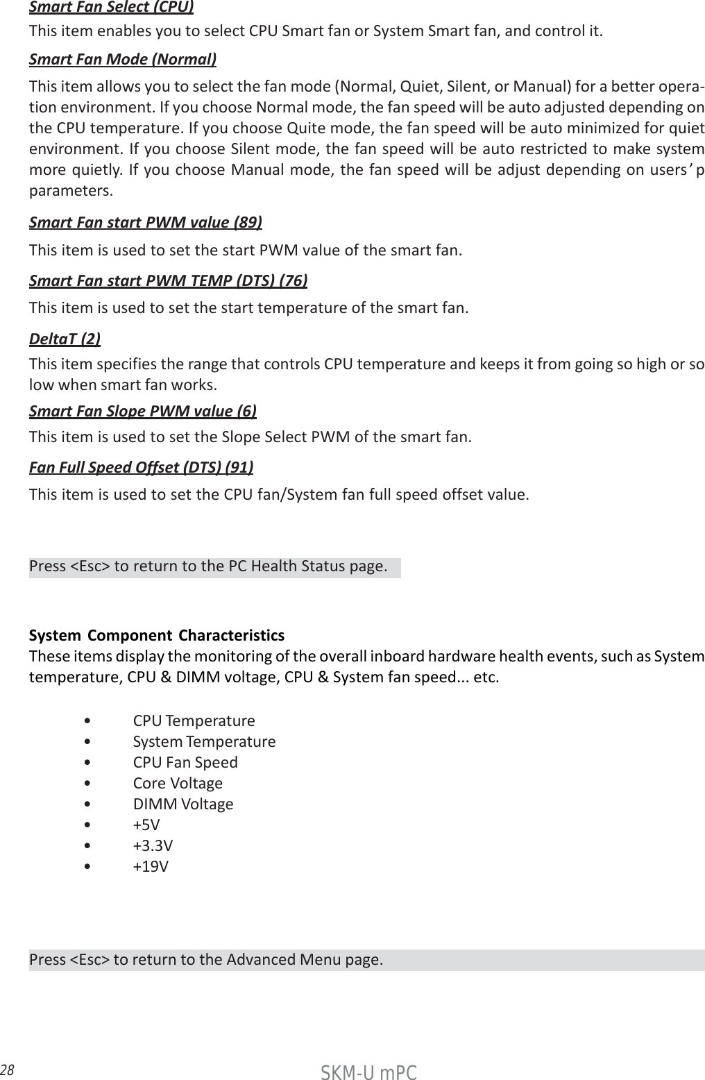
![27SKM-U mPC PC Health StatusOn motherboards support hardware monitoring, this item lets you monitor the parameters forcritical voltages, temperatures and fan speeds.Aptio Setup Utility - Copyright (C) 2016 American Megatrends, Inc.AdvancedPC Health StatusSmart Fan FunctionCPU Temperature (DTS) 75System Temperature 53O CCPU Fan Speed 2789 RPMCore Voltage 0.780VDIMM Voltage 1.212V+5V 5.040V+3.3V 3.264V+19V 19.080VTCC Activation Temperature (DTS) 100 Version 2.17.1255. Copyright (C) 2016 American Megatrends, Inc.Enabled / Disabled Onboard LANController : Select Screen : General Help : Change Opt.Enter : Select : Select Item : Previous Values : Optimized Defaults : Save & ExitESC : Exit+/-F1F2F3F4 Smart Fan FunctionScroll to this item and press <Enter> to view the following screen:Aptio Setup Utility - Copyright (C) 2016 American Megatrends, Inc.AdvancedSmart Fan Select [CPU]Smart Fan Mode [Normal]Smart Fan start PWM value 89Smart Fan start PWM TEMP (DTS) 76Deltat 2Smart Fan Slope PWM value 6Fan Full Speed Offset (DTS) 91 Version 2.17.1255. Copyright (C) 2016 American Megatrends, Inc.Enabled / Disabled Onboard LANController : Select Screen : General Help : Change Opt.Enter : Select : Select Item : Previous Values : Optimized Defaults : Save & ExitESC : Exit+/-F1F2F3F4](https://usermanual.wiki/ELITEGROUP-COMPUTER-SYSTEMS/SKM-U-MPCM/User-Guide-3171951-Page-35.png)
![29SKM-U mPC Power Management SetupThis page sets up some parameters for system power management operation.Aptio Setup Utility - Copyright (C) 2016 American Megatrends, Inc.AdvancedPower Management SetupResume By PME [Disabled]Resume By USB [Disabled]Resume By CIR [Disabled]Resume By RTC Alarm [Disabled]EUP Function [Enabled] Version 2.17.1255. Copyright (C) 2016 American Megatrends, Inc.About Resume ByPCI / PCI-E / LAN / Ext. USB3.1 PME : Select Screen : General Help : Change Opt.Enter : Select : Select Item : Previous Values : Optimized Defaults : Save & ExitESC : Exit+/-F1F2F3F4Resume By PME (Disabled)This item specify whether the system will be awakened from power saving modes when activity orinput signal of the specified hardware peripheral or components is detected.EUP Function (Enabled)This item allows user to enable or disable EUP support.Resume By USB (Disabled)This item allows you to enable/disable the USB device wakeup function from S3 mode.Resume By RTC Alarm (Disabled)The system can be turned off with a software command. If you enable this item, the system canautomatically resume at a fixed time based on the system’s RTC (realtime clock). Use the itemsbelow this one to set the date and time of the wake-up alarm. You must use an ATX power supplyin order to use this feature.Resume By CIR (Disabled)This item enables or disables you to wake up the system by IR.Press <Esc> to return to the Advanced Menu page.](https://usermanual.wiki/ELITEGROUP-COMPUTER-SYSTEMS/SKM-U-MPCM/User-Guide-3171951-Page-37.png)
![30SKM-U mPC ACPI SettingsThis item in the menu shows the highest ACPI sleep state when system enters suspend.Aptio Setup Utility - Copyright (C) 2016 American Megatrends, Inc.AdvancedACPI SettingsACPI Sleep State [S3 (Suspend to RAM)] Version 2.17.1255. Copyright (C) 2016 American Megatrends, Inc.Select the highest ACPI sleepstate the system will enterwhen the SUSPEND button ispressed. : Select Screen : General Help : Change Opt.Enter : Select : Select Item : Previous Values : Optimized Defaults : Save & ExitESC : Exit+/-F1F2F3F4ACPI Sleep State (S3 (Suspend to RAM))This item allows you to enter the ACPI S3 (Suspend to RAM) Sleep State (default).Press <Esc> to return to the Advanced Menu page.](https://usermanual.wiki/ELITEGROUP-COMPUTER-SYSTEMS/SKM-U-MPCM/User-Guide-3171951-Page-38.png)
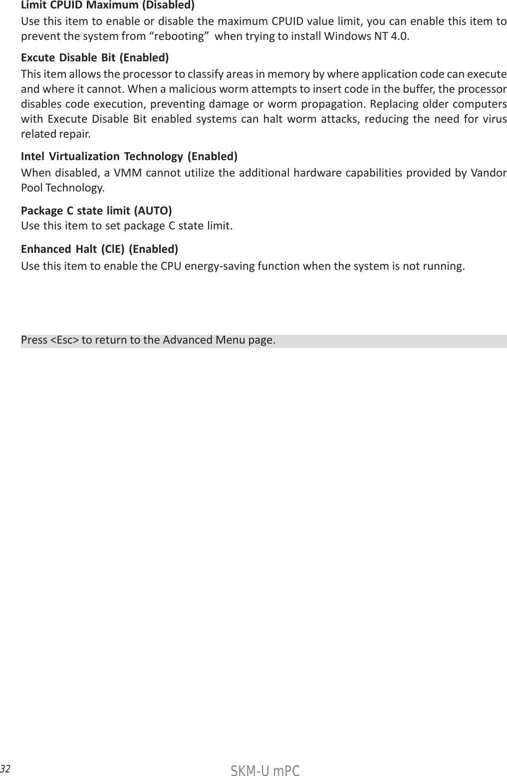
![31SKM-U mPC CPU ConfigurationThis item in the menu shows the CPU Configuration.Aptio Setup Utility - Copyright (C) 2016 American Megatrends, Inc.AdvancedCPU ConfigurationIntel (R) Core (TM) i5-6260U CPU @ 1.80GHzEM64T SupportedProcessor Speed 1800 MHzProcessor Stepping 406E3Microcode Revision 8AProcessor Cores 2Intel HT Technology SupportedIntel VT-x Technology SupportedHyper-threading [Enabled]Active Processor Cores [All]Limit CPUID Maximum [Disabled]Execute Disable Bit [Enabled]Intel Virtualization Technology [Enabled]Package C State limit [AUTO]Enhanced Halt (C1E) [Enabled] Version 2.17.1255. Copyright (C) 2016 American Megatrends, Inc.Enabled for windows XP andLinnux (OS optimaized forHyper-Threading Technology)and Disabled for other OS (OSnot optimaized forHyper-Threading Technolofy).when Disabled only one thraeadper enabled core is enabled. : Select Screen : General Help : Change Opt.Enter : Select : Select Item : Previous Values : Optimized Defaults : Save & ExitESC : Exit+/-F1F2F3F4Processor Speed (1800 MHz)This item shows the processor speed.EM64T (Supported)This item shows the computer supports EMT64.Processor Stepping (406E3)This item shows the processor stepping version.Intel (R) Core (TM) i5-6260U CPU @ 1.80GHzThis is display-only field and displays the informaton of the CPU installed in your computer.Microcode Revision (8A)This item shows the Microcode version.Processor Cores (2)This item shows the number of cores of the processor.Intel HT Technology (Supported)This item shows the computer supports Intel HT technology or not.Intel VT-x Technology (Supported)This item shows the computer supports Intel VT-x technology or not.Hyper-threading (Enabled)This item only available when the chipset supports Hyper-threading and you are using a Hyper-threading CPU.Active Processor Cores (All)Use this item to control the number of active processor cores.](https://usermanual.wiki/ELITEGROUP-COMPUTER-SYSTEMS/SKM-U-MPCM/User-Guide-3171951-Page-39.png)
![33SKM-U mPC ACPI SettingsThis item in the menu shows the highest ACPI sleep state when system enters suspend.Aptio Setup Utility - Copyright (C) 2016 American Megatrends, Inc.AdvancedSATA ConfigurationSATA Controller (s) [Enabled]SATA Mode [AHCI]SATA Port1Not PresentM.2TS128GMTS800 (128.0GB) Version 2.17.1255. Copyright (C) 2016 American Megatrends, Inc.Enable or disable the SATA Contrller : Select Screen : General Help : Change Opt.Enter : Select : Select Item : Previous Values : Optimized Defaults : Save & ExitESC : Exit+/-F1F2F3F4SATA Controllers (Enabled)This item allows you to to enable or disable SATA controllers.SATA Mode (AHCI)Use this item to select SATA mode.SATA Port1 (Not Present/M.2)This motherboard supports one SATA channel and one M.2_SSD, each channel allows one SATAdevice to be installed. Use these items to configure each device on the SATA channel and theM.2_SSD.Press <Esc> to return to the Advanced Menu page.](https://usermanual.wiki/ELITEGROUP-COMPUTER-SYSTEMS/SKM-U-MPCM/User-Guide-3171951-Page-41.png)
![34SKM-U mPC USB ConfigurationUse this item to show the information of USB configuration.Aptio Setup Utility - Copyright (C) 2016 American Megatrends, Inc.AdvancedUSB ConfigurationAll USB Devices [Enabled]Legacy USB Support [Enabled]USB3.0 Controller [Enabled] Version 2.17.1255. Copyright (C) 2016 American Megatrends, Inc.USB Support Parameters : Select Screen : General Help : Change Opt.Enter : Select : Select Item : Previous Values : Optimized Defaults : Save & ExitESC : Exit+/-F1F2F3F4All USB Devices (Enabled)Use this item to enable or disable all USB devicesLegacy USB Support (Enabled)Use this item to enable or disable support for legacy USB devices.USB3.1 Contrller (Enabled)Use this item to enable or disable USB3.1 contrller.Press <Esc> to return to the Advanced Menu page.](https://usermanual.wiki/ELITEGROUP-COMPUTER-SYSTEMS/SKM-U-MPCM/User-Guide-3171951-Page-42.png)
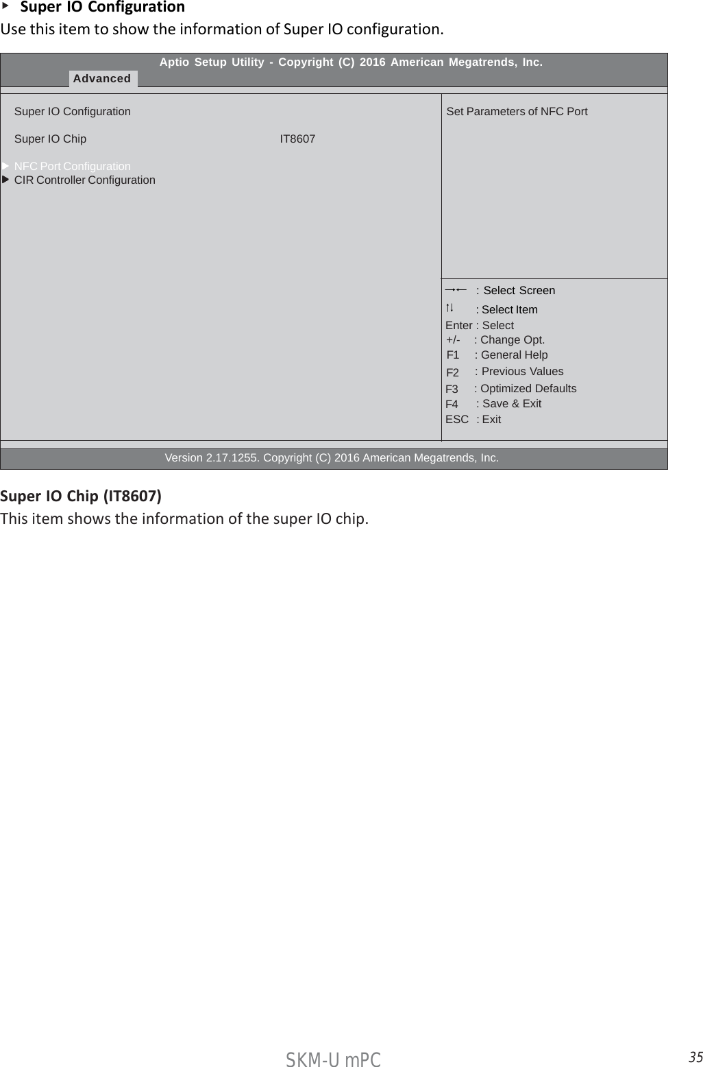
![36SKM-U mPC NFC Port ConfigurationScroll to this item and press <Enter> to view the following screen.Aptio Setup Utility - Copyright (C) 2016 American Megatrends, Inc.AdvancedNFC Port ConfigurationNFC Port [Enabled]Device Settings IO-3F8h; IRQ=4;Change Settings [Auto] Version 2.17.1255. Copyright (C) 2016 American Megatrends, Inc.Enabled or disabled NFC Port : Select Screen : General Help : Change Opt.Enter : Select : Select Item : Previous Values : Optimized Defaults : Save & ExitESC : Exit+/-F1F2F3F4NFC Port (Enabled)This item allows you to enable or disable NFC.Device Settings (IO=3F8h; IRQ=4;)This item shows the information of the device settings.Change Settings (Auto)Use this item to change device settings.Press <Esc> to return to the Advanced Menu page.Press <Esc> to return to the Super IO Configuration page.](https://usermanual.wiki/ELITEGROUP-COMPUTER-SYSTEMS/SKM-U-MPCM/User-Guide-3171951-Page-44.png)
![37SKM-U mPC CIR Controller ConfigurationScroll to this item and press <Enter> to view the following screen.Aptio Setup Utility - Copyright (C) 2016 American Megatrends, Inc.AdvancedCIR Controller ConfigurationCIR Controller [Enabled]Device Settings IO-3E0h; IRQ=10;Change Settings [Auto] Version 2.17.1255. Copyright (C) 2016 American Megatrends, Inc.Enabled or disabled CIRController : Select Screen : General Help : Change Opt.Enter : Select : Select Item : Previous Values : Optimized Defaults : Save & ExitESC : Exit+/-F1F2F3F4CIR Controller (Enabled)This item allows you to enable or disable CIR Controller.Device Settings (IO=3E0h; IRQ=10;)This item shows the information of the device settings.Change Settings (Auto)Use this item to change device settings.Press <Esc> to return to the Advanced Menu page.Press <Esc> to return to the Super IO Configuration page.](https://usermanual.wiki/ELITEGROUP-COMPUTER-SYSTEMS/SKM-U-MPCM/User-Guide-3171951-Page-45.png)
![38SKM-U mPC Trusted ComputingUse this item to show the information of trusted computing configuration.Aptio Setup Utility - Copyright (C) 2016 American Megatrends, Inc.AdvancedTPM20 Device FoundTPM Support [Enabled]TPM State [Enabled]HashPolicy [Sha-1] Version 2.17.1255. Copyright (C) 2016 American Megatrends, Inc.Enabled or disabled BIOSsupport for security device.O.S. will not show SecurityDevice. TCG EFI protocol andINDIA interface will not beavailable. : Select Screen : General Help : Change Opt.Enter : Select : Select Item : Previous Values : Optimized Defaults : Save & ExitESC : Exit+/-F1F2F3F4TPM Support (Enabled)Use this item to enable or disable the TPM support. OS will nor show TPM. Reset of platform isrequired.TPM State (Enabled)Use this item to enable or disable the security device.HashPolicy (Sha-1)Select the Hash policy to use. SHA-2 is most secure but might not be supported by all OperatingSystems.Press <Esc> to return to the Advanced Menu page.](https://usermanual.wiki/ELITEGROUP-COMPUTER-SYSTEMS/SKM-U-MPCM/User-Guide-3171951-Page-46.png)
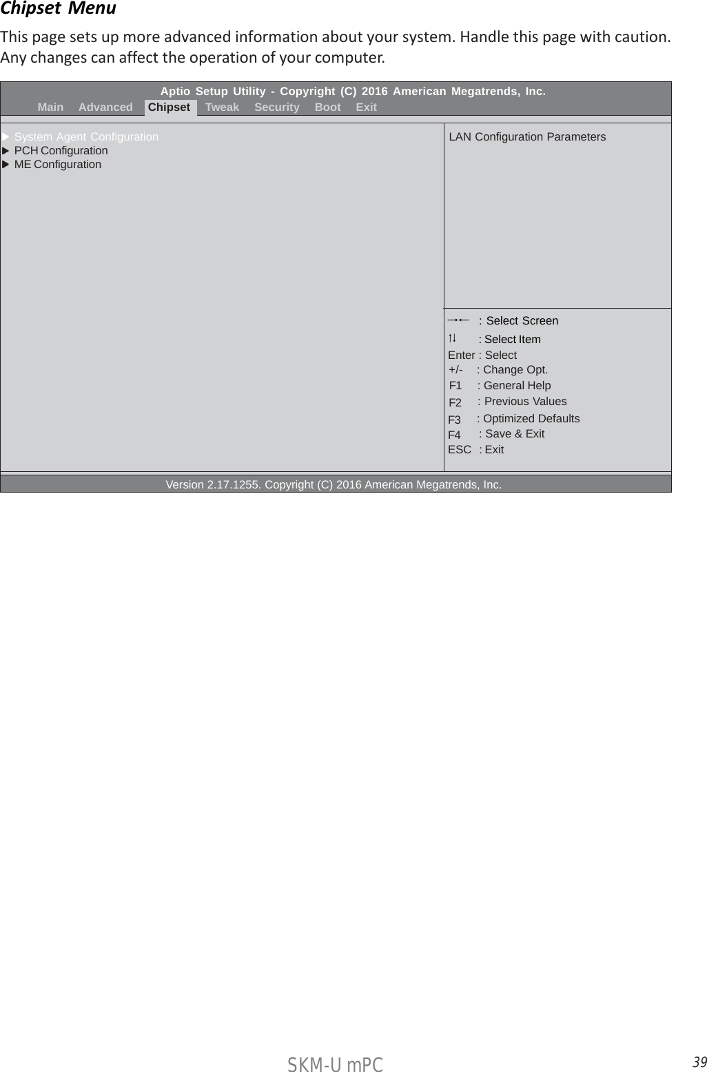
![40SKM-U mPC System Agent ConfigurationScroll to this item and press <Enter> and view the following screen:Press <Esc> to return to the Chipset Menu page.Aptio Setup Utility - Copyright (C) 2016 American Megatrends, Inc.ChipsetSystem Agent ConfigurationIGD Memory [64M]DVMT Memory [256M] Version 2.17.1255. Copyright (C) 2016 American Megatrends, Inc.Select DVMT 5.0 Pre-Allocated(Fixed) Graphics Memory sizeused by the Internal GraphicsDevice. : Select Screen : General Help : Change Opt.Enter : Select : Select Item : Previous Values : Optimized Defaults : Save & ExitESC : Exit+/-F1F2F3F4IGD Memory (64M)This item shows the information of the IGD (Internal Graphics Device) memory.DVMT Memory (256M)When set to Fixed Mode, the graphics driver will reserve a fixed positon of the system memory asgraphics memory, according to system and graphics equirements.](https://usermanual.wiki/ELITEGROUP-COMPUTER-SYSTEMS/SKM-U-MPCM/User-Guide-3171951-Page-48.png)
![41SKM-U mPC PCH ConfigurationScroll to this item and press <Enter> and view the following screen:Press <Esc> to return to the Chipset Menu page.Aptio Setup Utility - Copyright (C) 2016 American Megatrends, Inc.ChipsetPCH ConfigurationRestore AC Power Loss [Power Off]Audio ConfigurationAzalia HD Audio [Enabled] Version 2.17.1255. Copyright (C) 2016 American Megatrends, Inc.Select DVMT 5.0 Pre-Allocated(Fixed) Graphics Memory sizeused by the Internal GraphicsDevice. : Select Screen : General Help : Change Opt.Enter : Select : Select Item : Previous Values : Optimized Defaults : Save & ExitESC : Exit+/-F1F2F3F4Restore AC Power Loss (Power Off)This item enables your computer to automatically restart or return to its operating status.Azalia HD Audio (Enabled)This item enables or disables Azalia HD audio.](https://usermanual.wiki/ELITEGROUP-COMPUTER-SYSTEMS/SKM-U-MPCM/User-Guide-3171951-Page-49.png)
![42SKM-U mPC ME ConfigurationScroll to this item and press <Enter> and view the following screen:Press <Esc> to return to the Chipset Menu page.Aptio Setup Utility - Copyright (C) 2016 American Megatrends, Inc.ChipsetManagement Engine Technology ConfigurationME Control [Enabled]ME FW Version 11.0.0.1202 Version 2.17.1255. Copyright (C) 2016 American Megatrends, Inc.Enable/Disable ME Firmware : Select Screen : General Help : Change Opt.Enter : Select : Select Item : Previous Values : Optimized Defaults : Save & ExitESC : Exit+/-F1F2F3F4ME Control (Enabled)Use this item to enable or disable the ME Firmware.ME FW Version (9.1.0.1120)This item shows the ME FW version.](https://usermanual.wiki/ELITEGROUP-COMPUTER-SYSTEMS/SKM-U-MPCM/User-Guide-3171951-Page-50.png)
![43SKM-U mPCAptio Setup Utility - Copyright (C) 2016 American Megatrends, Inc. Main Advanced Chipset Tweak Security Boot ExitTweakTurbo Boost [Enabled]Intel (R) Core (TM) i5-6260U CPU @ 1.80GHzProcessor Speed 1800 MHzMemory Frequency 2133 MHzTotal Memory 4096 MB Version 2.17.1255. Copyright (C) 2016 American Megatrends, Inc.Turbo Boost : Select Screen : General Help : Change Opt.Enter : Select : Select Item : Previous Values : Optimized Defaults : Save & ExitESC : Exit+/-F1F2F3F4Tweak MenuThis page enables you to monitor or set some information of the processor you have installed inyour system.Turbo Boost (Enabled)This item allows you to enable or disable the turbo boost.Intel(R) Core (TM) i5-6260U CPU @ 1.80GHzThis is display-only field and displays the information of the CPU installed in your computer.Total Memory (4096 MB)This item shows the total memory.Processor Speed (1800 MHz)This item shows the current CPU speed.Memory Frequency (2133 MHz)This item shows the memory frequency.](https://usermanual.wiki/ELITEGROUP-COMPUTER-SYSTEMS/SKM-U-MPCM/User-Guide-3171951-Page-51.png)
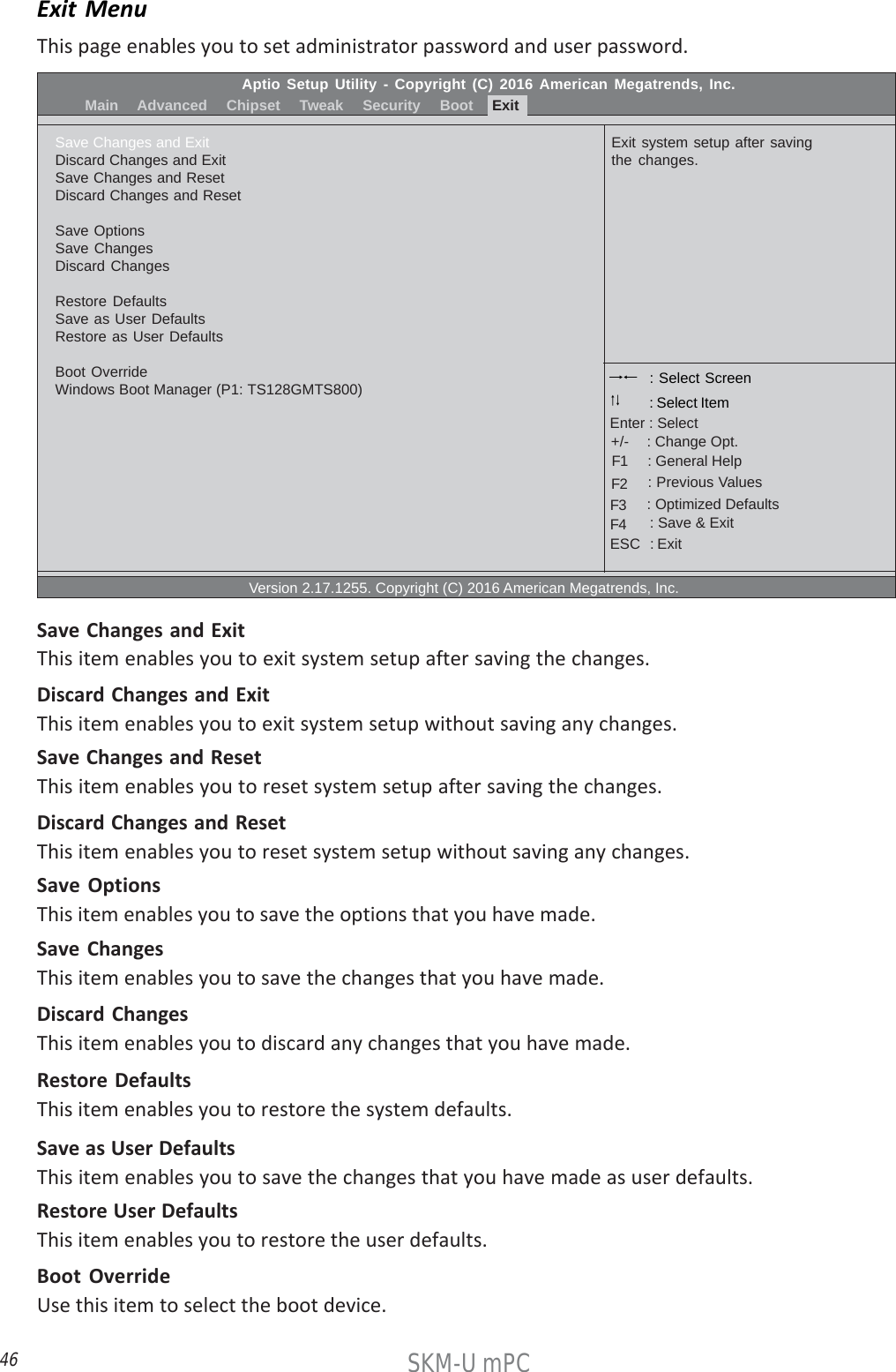
![44SKM-U mPCAptio Setup Utility - Copyright (C) 2016 American Megatrends, Inc. Main Advanced Chipset Tweak Security Boot ExitAdministrator PasswordAdministrator Password Not InstallUser Password Status Not InstallSystem Mode state SetupSecure Boot state Not ActiveSecure Boot [Enabled]Secure Boot Mode [Standard] Version 2.17.1255. Copyright (C) 2016 American Megatrends, Inc.Set Adiministrator Password : Select Screen : General Help : Change Opt.Enter : Select : Select Item : Previous Values : Optimized Defaults : Save & ExitESC : Exit+/-F1F2F3F4Security MenuThis page enables you to set administrator password and user password.Administrator Password Status (Installed)This item shows administrator password installed or not.User Password Status (Not Installed)This item shows user password installed or not.System Mode state (Setup)This item shows system mode setup or not.Secure Boot state (Not Active)This item allows you to enable or disable the secure boot state.Secure Boot (Enabled)This item is used to control the secure boot flow, it is possible only if system runs in User Mode.Secure Boot Mode (Standard)This item is used to select secure booe mode, when you select standard mode, secure boot policyis fixed; when you select custom mode, the image execution policy and secure boot key datebasesare changeable.](https://usermanual.wiki/ELITEGROUP-COMPUTER-SYSTEMS/SKM-U-MPCM/User-Guide-3171951-Page-52.png)
![45SKM-U mPCAptio Setup Utility - Copyright (C) 2016 American Megatrends, Inc. Main Advanced Chipset Tweak Security Boot ExitBoot ConfigurationOperating System Select [Windows 8.x / 10]Launch PXE OpROM [Disabled]Launch Storage OpROM [Enabled]Bootup MumLock State [On]Quiet Boot [Enabled]Boot Mode Select [UEFI]Fixed BOOT ORDER PrioritiesBoot Option #1 [Hard Disk: windows B...]Boot Option #2 [USB Hard Disk]Boot Option #3 [USB CD/DVD]Boot Option #4 [USB Key]Boot Option #5 [USB Floppy]Boot Option #6 [Network]UEFI Hard Disk Drive Priorities Version 2.17.1255. Copyright (C) 2016 American Megatrends, Inc.Windows 7 or other OS: Bootpolicy for Legacy OSWindows 8.x / 10: Boot policyfor UEFI OS withoutCompatibility SupportModule (CSM)Manual: User cusomiazed CSMparameters & boot policy : Select Screen : General Help : Change Opt.Enter : Select : Select Item : Previous Values : Optimized Defaults : Save & ExitESC : Exit+/-F1F2F3F4Boot MenuThis page enables you to set the keyboard NumLock state.UEFI Hard Disk Drive PrioritiesThis item enables you to specify the sequence of loading the operating system from the installingHard Disk drive.(This item only shows when there is boot device connecting)Press <Enter> to see the submenu.Operating System Select (Windows 8.x / 10)This item is used to select the operating system.Launch PXE OpROM (Disabled)This item enables or disables launch PXE Option ROMLaunch Storage OpROM (Enabled)This item enables or disables the Storage OpROM.Bootup NumLock State (On)This item enables you select NumLock state.Quiet Boot (Enabled)This item enables or disables the boot LOGO.Boot Mode Select (UEFI)Use this item to select boot mode.Boot Option #1~6 (UEFI)These items show the boot priorities and can be used to set the boot priorities of various devicecategories.](https://usermanual.wiki/ELITEGROUP-COMPUTER-SYSTEMS/SKM-U-MPCM/User-Guide-3171951-Page-53.png)