ELITEGROUP COMPUTER SYSTEMS TRBC41CD1 Wireless Motherboard User Manual TR10CD3 MB guide 04 14
ELITEGROUP COMPUTER SYSTEMS CO., LTD Wireless Motherboard TR10CD3 MB guide 04 14
User manual
FEDERAL COMMUNICATIONS
COMMISSION INTERFERENCE
STATEMENT
This equipment has been tested and found to
comply with the limits for a Class B digital
device, pursuant to part 15 of the FCC Rules.
These limits are designed to provide
reasonable protection against harmful
interference in a residential installation. This
equipment generates, uses and can radiate
radio frequency energy and, if not installed and
used in accordance with the instructions, may
cause harmful interference to radio
communications. However, there is no
guarantee that interference will not occur in a
particular installation. If this equipment does
cause harmful interference to radio or
television reception, which can be determined
by turning the equipment off and on, the user is
encouraged to try to correct the interference by
one or more of the following measures:
Reorient or relocate the receiving antenna.
Increase the separation between the equipment
and receiver.
Connect the equipment into an outlet on a
circuit different from that to which the receiver
is connected.

2
CAUTION:
Any changes or modifications not expressly
approved by the grantee of this device could void
the user's authority to operate the equipment.
This device complies with Part 15 of the FCC Rules.
Operation is subject to the following two conditions:
(1) this device may not cause harmful interference,
and (2) this device must accept any interference
received, including interference that may cause
undesired operation.
RF exposure warning
This equipment must be installed and operated
in accordance with provided instructions and the
antenna(s) used for this transmitter must be
installed to provide a separation distance of at least
20 cm from all persons and must not be co-located
or operating in conjunction with any other antenna
or transmitter. End-users and installers must be
provide with antenna installation instructions and
transmitter operating conditions for satisfying RF
exposure compliance.

3
End Product Labeling
This transmitter module is authorized only for use in
device where the antenna may be installed such
that 20cm may be maintained between the antenna
and users. The final end product must be labeled in
a visible area with the following: "Contains FCC ID:
WL6-TRBC41CD1”
Information for the OEMs and Integrators
The following statement must be included with all
versions of this document supplied to an
OEM or integrator, but should not be distributed to
the end user.
1) This device is intended for OEM integrators only.
2) Please see the full Grant of Equipment document
for other restrictions.
This radio transmitter FCC ID: WL6-TRBC41CD1
has been approved by FCC to operate with the
antenna types listed below with the maximum
permissible gain and required antenna impedance
for each antenna type indicated. Antenna types not
included in this list, having a gain greater than the
maximum gain indicated for that type, are strictly
prohibited for use with this device.

4
Antenna List
No. Manufacturer Part No. Antenna Type Peak Gain
WGT 13H130-JV1050 PIFA Antenna(Main) 1.65 dBi For 2.4GHz
2.36 dBi For 5.15~5.35GHz
1.78 dBi For 5.47~5.725GHz
1.78 dBi For 5.725~5.850GHz
1
Pulse 02H475-006500 Chip Antenna (Aux) 3.2 dBi For 2.4GHz
4.2 dBi For 5.15~5.35GHz
4.2 dBi For 5.47~5.725GHz
4.2 dBi For 5.725~5.850GHz
JEM 13H130-JV1070 PIFA Antenna (Main) 1.77 dBi For 2.4GHz
1.55 dBi For 5.15~5.35GHz
-0.56 dBi For 5.47~5.725GHz
-0.14 dBi For 5.725~5.850GHz
2
Pulse 02H475-006500 Chip Antenna (Aux) 3.2 dBi For 2.4GHz
4.2 dBi For 5.15~5.35GHz
4.2 dBi For 5.47~5.725GHz
4.2 dBi For 5.725~5.850GHz
Note: The antenna connector is I-PEX type.
5
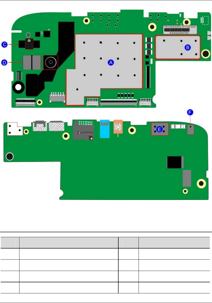
Motherboard Layout
Main components
No. Name No. Name
A CPU+PMIC+DDR E TPM
B EMMC+Audio Codec F Microphone
C Microphone
D Rear facing camera
6
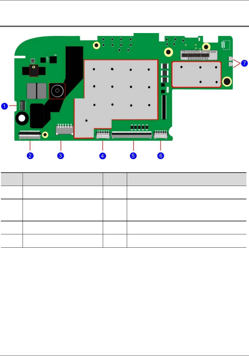
System connectors
No. Name No. Name
1 Power key connector 5 LCD Connector
2 Front camera
connector 6 Touch panel connector
3 Battery Connector 7 Speaker Connectors
4 Volumkey connector
7
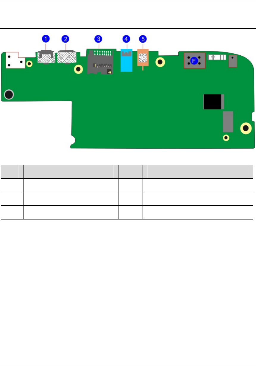
I/O Ports
No. Name No. Name
1 Micro USB port 4 Headphone plug
2 Mini HDMI port 5 DC-in jack
3 Micro SD card slot