Elk ELK-6030X PIR Sensor User Manual 6030 PIR Instruction 4 pg sig v3 pmd
ELK Products, Inc. PIR Sensor 6030 PIR Instruction 4 pg sig v3 pmd
UserManual.wiki
>
Elk
>
ELK 6030X User Manual
User Manual
Navigation menu
Upload a User Manual
Namespaces
Wiki Guide
HTML
PDF
Info
Views
User Manual
Discussion / Help
Navigation

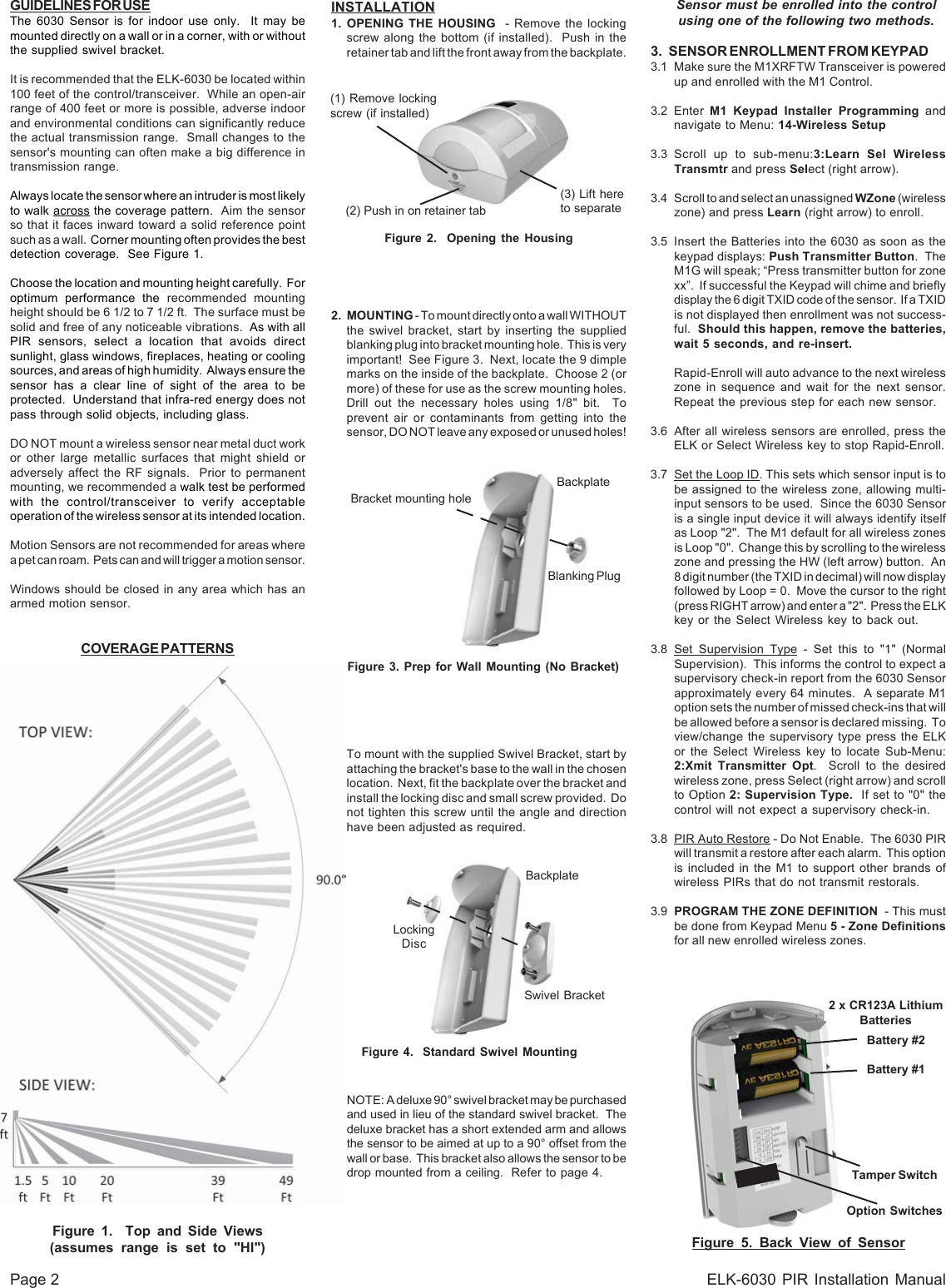
![Page 4 ELK-6030 PIR Installation ManualLIMITATIONSWhile the 6030 Passive Infrared (PIR) Motion Detectoris a highly reliable intrusion detection device, it does notoffer guaranteed protection against burglary. Anyintrusion detection device is subject to compromise orfailure to warn for a variety of reasons:PIR Detectors can only detect movement within aspecific coverage area as diagrammed in this manual.To detect movement, the PIR Detector senses theinfrared energy that is emitted from an intruder movingacross the sensor's field of view.PIR Detectors do not provide volumetric area protection.They create multiple beams of protection. Intrusion canonly be detected in unobstructed areas covered bythose beams.PIR Detectors cannot detect motion or intrusion thattakes place behind walls, ceilings, floors, closed doors,glass partitions, glass doors, or windows.The radio transceiver only provides communications.It does not have anything to do with detecting motion.LIMITED WARRANTYThe 6030 Wireless PIR Sensor is warranted to be freefrom defects and workmanship for a period of 2 yearsfrom date of manufacture. Batteries used with wirelessdevices are not warranted. Elk makes no warranty,express or implied, including that of merchantability orfitness for any particular purpose with regard to batteriesused with wireless devices. Refer to Elk’s website forfull warranty statement and details.PO Box 100 3266 US Hwy 70 WestHildebran, NC 28637828-397-4200 828-397-4415 Fax http://www.elkproducts.comPrinted in USAL645 Rev. A 11/19/12A deluxe 90° swivel bracket may be purchased and usedin lieu of the standard swivel bracket. This bracket hasa short extended arm and allows the sensor to be aimedat up to a 90° offset from the wall or base. This bracketalso allows the sensor to be drop mounted from a ceiling.OPTIONAL DELUXE 90° SWIVEL MOUNTANTI-TAMPER SWITCHThis switch detects the separation of the front housingfrom the backplate. When this is tripped a signal istransmitted to the control/transceiver, causing theassociated zone to become violated. Snapping the fronthousing back onto the backplate transmits a restoral.Note: Tamper can be ignored for any sensor (zone)by setting its Zone Type to 1=Normally Closed.FUNCTIONAL 'SYSTEM' TESTINGA system test should be done by physically walkingacross the 6030 coverage pattern while the system isfully armed. NOTE: Allow time for the Sleep Cycle Timerto expire before testing. Always notify the CentralMonitoring Station prior to performing any testing.BATTERIESThe 6030 battery compartment holds 2 x CR123A Lithiumbatteries. The estimated service life of these batteriesis 5 to 7 years in typical residential usage with the SleepCycle set to LG (Long),Battery #1 (lower) is supervised for low voltage. Whenthe sensor detects the voltage has reached 2.6 VDC orless (under load), a Sensor Low Battery trouble will betransmitted to the control/transceiver. This trouble willbe attached to all future transmissions until fresh newbatteries are installed. Battery #1 is the primary powersource for all critical functions (motion detect and radiotransmission) of the 6030 sensor.Battery #2 (upper) is not-supervised for low voltage.This battery is a secondary (reserve) power source forthe 6030 critical functions, but it is the primary (sole)power source for the White Security/Convenience LED.The White Security/Convenience LED will not operatewithout a good battery installed in Battery #2 location.We strongly recommend installing a battery in bothlocations. These 2 batteries are electrically isolated insuch a way that critical functions of the 6030 can drawpower either battery, but the White Convenience LEDcan only draw power from Battery #2.To clear a sensor low battery trouble condition, installnew batteries and then trip the sensor a couple of times.This clears the low battery trouble and sends "all good"to the control/transceiver.Caution: Excessive use of the White Security/Convenience LED will rapidly reduce the life ofBattery #2. More importantly, because the 6030sensor is able to tap into Battery #2 for secondarypower, any reduction of its life naturally reducesthe overall operational life of the sensor. If maximumsensor operational life is the top priority, theSecurity/Convenience LED may be disabled byturning DIP Switch #3 OFF.BATTERY REPLACEMENTUse only CR123A 3V Lithiums. Replace both batteriesat the same time. If possible, both batteries shouldhave the same manufactured date code. Replacementscan be obtained from Alarm Distributors.1. Remove sensor from back housing.2. Observe correct polarity when installing the newbatteries. Do not bend or damage the metal batteryholder contacts. Approved Batteries: 3V Lithium -Panasonic CR123A, Duracell DL123A, Varta CR123A,Sanyo CR123A3. Re-test sensor operation with the control.BATTERY WARNING: Risk of fire, explosionand burns. Do not attempt to recharge ordisassemble. Do not incinerate or expose toheat above 212° F (100° C). Dispose of usedbatteries properly. Keep away from children.ACTIVATING THE WHITESECURITY/CONVENIENCE LIGHT TMThis high-intensity LED projects light out the front of thesensor. There are five (5) modes of operation: 1)Flashduring an audible alarm activation. 2)On Solid whenmotion is detected and either the control is armed AWAYmode or when output 4 is On. 3) Flash on command fromcontrol. 4)On Solid by command from control. 5)Quickblip in walk test mode when motion is detected.Note: For all conditions EXCEPT Walk Test, thewhite LED may be totally disabled by DIP Switch #3.1) Flash upon audible alarm activationIf DIP Switch #3 is ON, ANY audible alarm activationfrom the Control (not Silent 24hr Police) will cause theWhite LED to flash. This flash will continue until eitherthe Alarm Cutoff timer expires, the Control is disarmed,or Battery #2 (the upper battery) is drained.Note: The 6030 reacts to two-way wireless commandsfrom the M1 Control. Please understand that it cantake several seconds for the 6030 to receive acommand. The time delay is typically 8 seconds orless. Be prepared for this delay during testing andoperation. Do not expect instantaneous reaction.Activating the white LED via ElkRP RulesThe white LED may be controlled via ElkRP Rules usingM1 Outputs 4, 5, & 6. These outputs do not appear onthe M1 board and are generally only used as rule flags.The 6030 detects the state of these 3 outputs andperforms as follows:2) On Solid if Motion Detected while armed to AwayAny motion detected while the control is armed to AWAYmode will result in the white LED turning On for approx.18 seconds. {DIP Switch #3 must be ON}OR On Solid if Motion Detected and Output 4 is onAny motion detected while M1 Output 4 is On will causethe white LED to turn On for approx. 18 seconds.Additional motion can restart this time. Output 4 can beturned On at a specific time, date, or condition using anElkRP rule. E.G. "When Sunset - Then Turn Output 4On." Use another ElkRP rule to turn Output 4 Off whenthis LED action is no longer desired. E.G. "When Sunrise- Then Turn Output 4 Off."3) Flash - on command [M1 Output 5]When the 6030 sees M1 Output 5 turn On it will start thewhite LED flashing for approx. 18 seconds. Output 5can be turned On at a specific time, date, or conditionusing an ElkRP rule. E.G. "When 5:30PM (Close Time?)- Then Turn Output 5 On for 15 seconds." (15 secondsis an arbitrary value) The crucial point is that Output 5must first be turned Off before it can again be turnedback On to restart the white LED Flash.Solid On - on command [M1 Output 6]When the 6030 sees M1 Output 6 turn On it will turn thewhite LED On Solid for approx. 18 seconds. Output 6can be turned On at specific time, date, or condtionusing an ElkRP rule. E.G. When Entry Delay Starts- Then Turn Output 6 On for 15 seconds." (15 secondsis an arbitrary value) The crucial point is that Output 6must first be turned Off before it can be turned backOn to restart the white LED Solid On.Examples of Rules for the Security/Convenience Light:Whenever Sunset Then Turn On Output 4 On.Whenever Sunrise Then Turn Off Output 4 Off.Whenever Time is 6:00pm (e.g. dinner time) Then Turn On Output 5 for 15 seconds.Whenever Entry Delay Starts Then Turn On Output 6 for 15 seconds.NOTES: DIP Switch #3 allows each individual 6030sensor to be excluded from the above operations.FCC COMPLIANCE STATEMENT:This device complies with Part 15 of the FCC Rules.Operation is subject to the following two conditions:(1) this device may not cause harmful interference,and (2) this device must accept any interferencereceived, including interference that may causeundesired operation.Part # Description FCC ID #ELK-6030 Wireless PIR Sensor TMA ELK-6030NOTE: ELK PRODUCTS IS NOT RESPONSIBLEFOR ANY CHANGES OR MODIFICATIONS NOTEXPRESSLY APPROVED BY THE PARTYRESPONSIBLE FOR COMPLIANCE. SUCHMODIFICATIONS COULD VOID THE USER’SAUTHORITY TO OPERATE THE EQUIPMENT.BackplateDeluxe 90°SwivelBracketLockingDiscFigure 8. Deluxe 90° Swivel Bracket(Separate purchase P/N: ELK-603022)](https://usermanual.wiki/Elk/ELK-6030X/User-Guide-1913807-Page-4.png)