Elk ELK-6030X PIR Sensor User Manual 6030 PIR Instruction 4 pg sig v3 pmd
ELK Products, Inc. PIR Sensor 6030 PIR Instruction 4 pg sig v3 pmd
Elk >
User Manual
ELK-6030 PIR Installation Manual Page 1
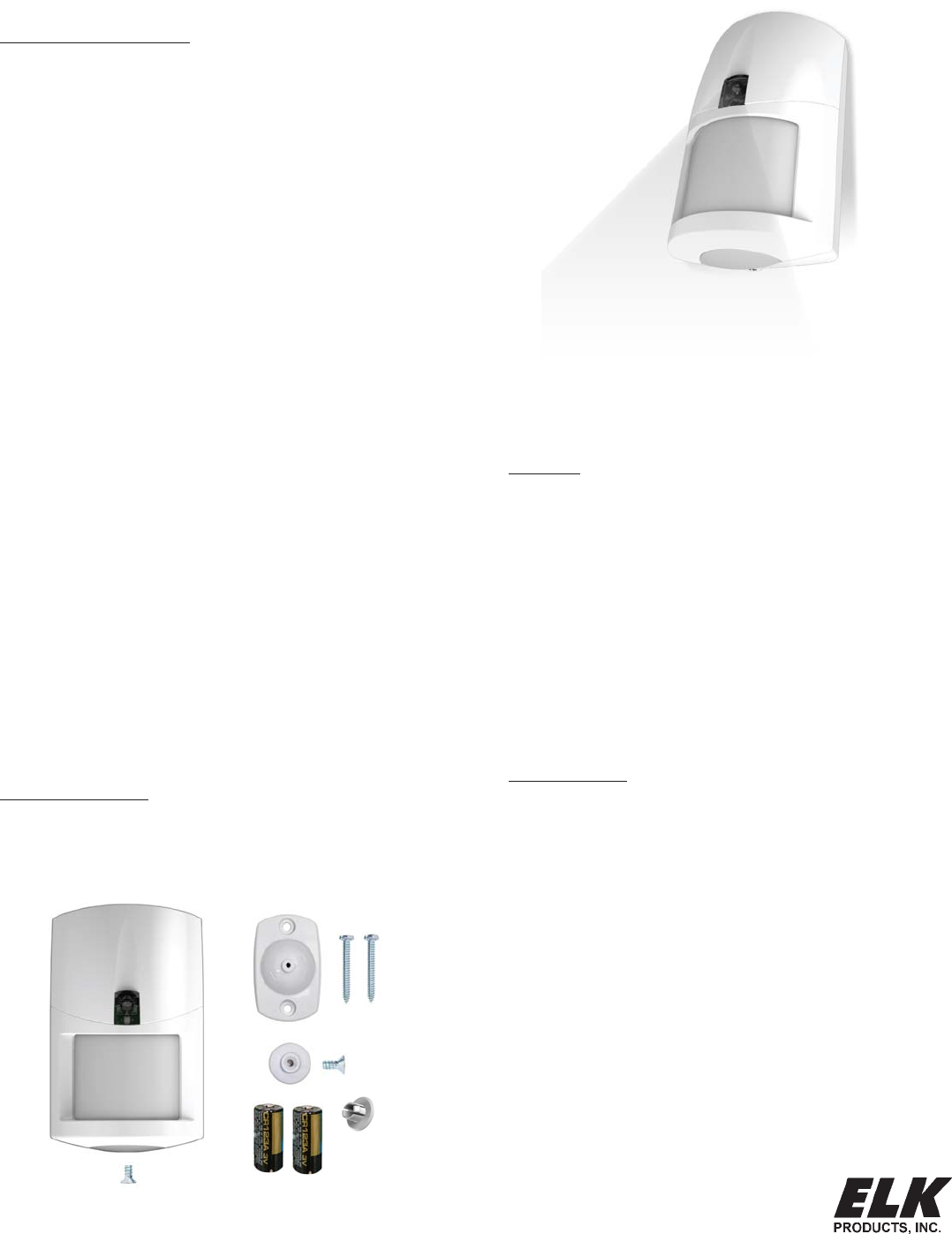
ELK-6030
Wireless PIR Motion Sensor
For the latest downloadable version of this manual visit our website: http://www.elkproducts.com
Installation and Setup Guide
APPLICATION & OVERVIEW
The ELK-6030 Wireless PIR Motion Sensor is designed for use with
control/transceivers that accept Elk's two-way technology; such as
the ELK-M1XRFTW. It is intended for use in residential and light
commercial installations and incorporates many features designed to
ensure its reliable performance.
The dual element pyroelectric sensor in the 6030 detects movement
within a specific coverage area, by sensing the infrared energy that is
emitted from an intruder moving across the sensor's field of view. A
change in the infrared energy creates a temperature change in the
sensor's zones, which is then processed to determine if the occurrence
qualifies as a legitimate motion detect event. If it does then the built-in
radio will be triggered.
The two-way radio (RF) in the 6030 transmits alarm, tamper, supervisory,
and low battery messages to the control/receiver. Each sensor has a
unique TXID number which is enrolled into the control during installation.
With its two-way capability, the 6030 radio listens after every
transmission for a positive acknowledgment from the control. This
makes the sensor very energy efficient since it doesn't waste battery
power repeating transmissions unless they are not acknowledged.
Like all battery powered motion detectors, the 6030 has a mandatory
sleep cycle function to help extend the battery life. After detecting
motion, the sensor's radio will transmit the event to the control and wait
for acknowledgment. Upon acknowledgment the sensor will enter the
mandatory sleep cycle. During the sleep cycle time it cannot transmit
additional events. There are two (2) time choices for the sleep cycle, both
selected via DIP Switch #4. After the sleep cycle expires the sensor will
once again be capable of transmitting a new event.
The 6030 introduces the industry's first Security/Convenience Light.TM
This high-intensity white LED projects a beam of light out in front of the
sensor. It offers five (5) activation/operation modes: 1)Flash during
any audible alarm activation as a visual deterent. 2)On Solid for a timed
period when motion is detected and control is armed to the Away mode.
(This can be disabled or modified so that it only works during certain
conditions or time periods) 3)Flash on command for a timed period as
a special attention grabber or general purpose indicator. 4)On Solid on
command for a timed period to illuminate the immediate area (camera
surveillance, etc.) 5)Quick blip in walk test mode when a coverage zone
is tripped.
FEATURES
• Wireless two-way communication
• Dual-element pyroelectric sensor
• Selectable pulse count
• Selectable Hi/Lo range
• Excellent immunity from white light, RF, and ESD interference
• Green/Red (Bi-Color) RF Acknowledge LED
• White LED - Security/Convenience Light TM
• Long life Lithium batteries {supplied}
• Low battery trouble signal
• Sleep Cycle "Battery Saver" (2 time settings)
• Hourly supervision (check-in) signals
• Cover tamper protection
• Swivel mounting bracket included
• Optional deluxe 90° swivel bracket for ceilings sold separately
SPECIFICATIONS
• Dimensions: 2.8"W x 4.4"H x 1.9"D
• Mounting Height: 6 1/2 to 7 1/2' ft
• Sensor: Dual element pyroelectric
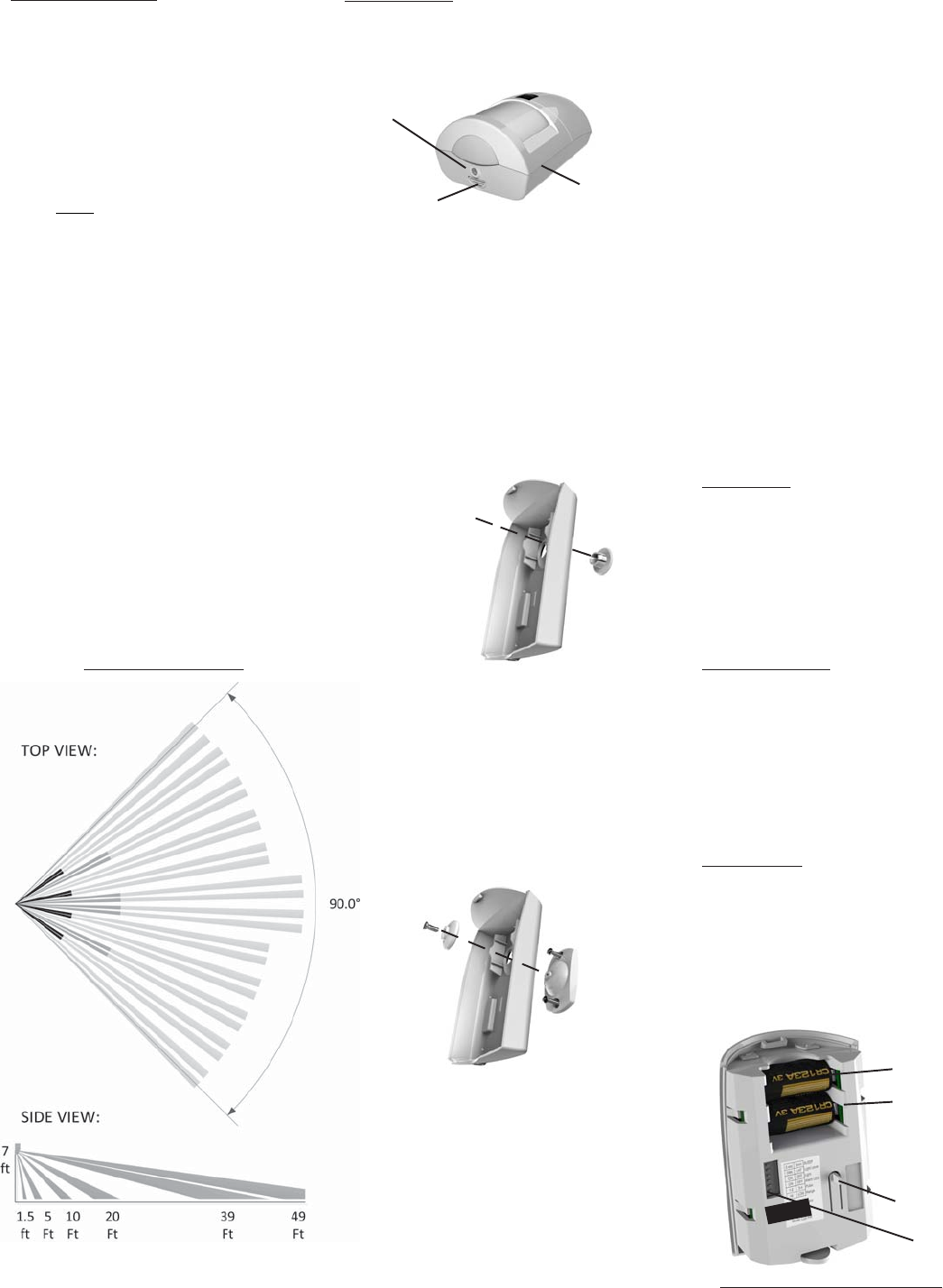
• Coverage: 39 ft x 49 ft (12m x 15m) @ 88.2°
20 dual element zones (2 Long, 10 intermediate, 4 mid, 4 short)
plus look down (creep zone)
• Pulse Count: 1-2 or 3-4, selectable
• Sleep Time: Selectable 30 sec. or 120 sec.
• RF Signal Acknowledge Indication: Green/Red (Bi-Color) LED
• Security/Convenience Light: White LED
• Warm Up Period: 10 seconds
• Operating Voltage: 3.0 Volts DC
• Battery Type & Size: 2 x Lithium CR123A
• Quiescent Current: < 10 µA
• Operating Temp: 32° to +120° degrees F
• Humidity: 95% RH (max.), non-condensing
• Frequency: 902 - 928 Mhz channel hopping
PACKAGE CONTENTS
1 - 6030 PIR electronics assembly & back housing
1 - Standard swivel bracket, locking disc, screws & anchors
1 - Blanking plug
2 - CR123A Lithium Batteries
1 - Cover locking screw
UNIQUE 'INDUSTRY FIRST'
SECURITY/CONVENIENCE LIGHT TM
Page 2 ELK-6030 PIR Installation Manual
INSTALLATION
1. OPENING THE HOUSING - Remove the locking
screw along the bottom (if installed). Push in the
retainer tab and lift the front away from the backplate.
2. MOUNTING - To mount directly onto a wall WITHOUT
the swivel bracket, start by inserting the supplied
blanking plug into bracket mounting hole. This is very
important! See Figure 3. Next, locate the 9 dimple
marks on the inside of the backplate. Choose 2 (or
more) of these for use as the screw mounting holes.
Drill out the necessary holes using 1/8" bit. To
prevent air or contaminants from getting into the
sensor, DO NOT leave any exposed or unused holes!
To mount with the supplied Swivel Bracket, start by
attaching the bracket's base to the wall in the chosen
location. Next, fit the backplate over the bracket and
install the locking disc and small screw provided. Do
not tighten this screw until the angle and direction
have been adjusted as required.
Sensor must be enrolled into the control
using one of the following two methods.
3. SENSOR ENROLLMENT FROM KEYPAD
3.1 Make sure the M1XRFTW Transceiver is powered
up and enrolled with the M1 Control.
3.2 Enter M1 Keypad Installer Programming and
navigate to Menu: 14-Wireless Setup
3.3 Scroll up to sub-menu:3:Learn Sel Wireless
Transmtr and press Select (right arrow).
3.4 Scroll to and select an unassigned WZone (wireless
zone) and press Learn (right arrow) to enroll.
3.5 Insert the Batteries into the 6030 as soon as the
keypad displays: Push Transmitter Button. The
M1G will speak; “Press transmitter button for zone
xx”. If successful the Keypad will chime and briefly
display the 6 digit TXID code of the sensor. If a TXID
is not displayed then enrollment was not success-
ful. Should this happen, remove the batteries,
wait 5 seconds, and re-insert.
Rapid-Enroll will auto advance to the next wireless
zone in sequence and wait for the next sensor.
Repeat the previous step for each new sensor.
3.6 After all wireless sensors are enrolled, press the
ELK or Select Wireless key to stop Rapid-Enroll.
3.7 Set the Loop ID. This sets which sensor input is to
be assigned to the wireless zone, allowing multi-
input sensors to be used. Since the 6030 Sensor
is a single input device it will always identify itself
as Loop "2". The M1 default for all wireless zones
is Loop "0". Change this by scrolling to the wireless
zone and pressing the HW (left arrow) button. An
8 digit number (the TXID in decimal) will now display
followed by Loop = 0. Move the cursor to the right
(press RIGHT arrow) and enter a "2". Press the ELK
key or the Select Wireless key to back out.
3.8 Set Supervision Type - Set this to "1" (Normal
Supervision). This informs the control to expect a
supervisory check-in report from the 6030 Sensor
approximately every 64 minutes. A separate M1
option sets the number of missed check-ins that will
be allowed before a sensor is declared missing. To
view/change the supervisory type press the ELK
or the Select Wireless key to locate Sub-Menu:
2:Xmit Transmitter Opt. Scroll to the desired
wireless zone, press Select (right arrow) and scroll
to Option 2: Supervision Type. If set to "0" the
control will not expect a supervisory check-in.
3.8 PIR Auto Restore - Do Not Enable. The 6030 PIR
will transmit a restore after each alarm. This option
is included in the M1 to support other brands of
wireless PIRs that do not transmit restorals.
3.9 PROGRAM THE ZONE DEFINITION - This must
be done from Keypad Menu 5 - Zone Definitions
for all new enrolled wireless zones.
GUIDELINES FOR USE
The 6030 Sensor is for indoor use only. It may be
mounted directly on a wall or in a corner, with or without
the supplied swivel bracket.
It is recommended that the ELK-6030 be located within
100 feet of the control/transceiver. While an open-air
range of 400 feet or more is possible, adverse indoor
and environmental conditions can significantly reduce
the actual transmission range. Small changes to the
sensor's mounting can often make a big difference in
transmission range.
Always locate the sensor where an intruder is most likely
to walk across the coverage pattern. Aim the sensor
so that it faces inward toward a solid reference point
such as a wall. Corner mounting often provides the best
detection coverage. See Figure 1.
Choose the location and mounting height carefully. For
optimum performance the recommended mounting
height should be 6 1/2 to 7 1/2 ft. The surface must be
solid and free of any noticeable vibrations. As with all
PIR sensors, select a location that avoids direct
sunlight, glass windows, fireplaces, heating or cooling
sources, and areas of high humidity. Always ensure the
sensor has a clear line of sight of the area to be
protected. Understand that infra-red energy does not
pass through solid objects, including glass.
DO NOT mount a wireless sensor near metal duct work
or other large metallic surfaces that might shield or
adversely affect the RF signals. Prior to permanent
mounting, we recommended a walk test be performed
with the control/transceiver to verify acceptable
operation of the wireless sensor at its intended location.
Motion Sensors are not recommended for areas where
a pet can roam. Pets can and will trigger a motion sensor.
Windows should be closed in any area which has an
armed motion sensor.
NOTE: A deluxe 90° swivel bracket may be purchased
and used in lieu of the standard swivel bracket. The
deluxe bracket has a short extended arm and allows
the sensor to be aimed at up to a 90° offset from the
wall or base. This bracket also allows the sensor to be
drop mounted from a ceiling. Refer to page 4.
COVERAGE PATTERNS
(2) Push in on retainer tab
(3) Lift here
to separate
Figure 2. Opening the Housing
(1) Remove locking
screw (if installed)
Tamper Switch
2 x CR123A Lithium
Batteries
Option Switches
Figure 5. Back View of Sensor
Battery #2
Battery #1
Figure 3. Prep for Wall Mounting (No Bracket)
Blanking Plug
Bracket mounting hole
Backplate
Figure 4. Standard Swivel Mounting
Swivel Bracket
Locking
Disc
Backplate
Figure 1. Top and Side Views
(assumes range is set to "HI")
ELK-6030 PIR Installation Manual Page 3
6. After enrolling the sensor into the control and setting
the Option Switches, reposition sensor over the
back housing and snap it into place. This action will
activate the Walk Test mode for the next 10
minutes. Perform an immediate Walk Test accord-
ing to the procedure that follows.
7. If the swivel mount bracket was used then it will be
possible to adjust (fine tune) the Sensor coverage.
If the swivel bracket was not used, and the sensor
was fixed mounted to the wall, the coverage pattern
is based on the mounting height and position.
8. After Walk Testing has been completed, secure the
sensor to the back housing using the locking screw
provided (small countersunk screw).
WALK TESTING
Walk testing is a way to verify that a sensor has been
installed in the optimum location and is working properly.
This involves taking short and deliberate steps across
the coverage zones in both directions. When motion is
detected the White LED should blink once followed by
a quick blink of the Green RF ACK LED. The Green LED
is indicating that the sensor transmitted and was
acknowledged by the control/transceiver. For more
information read the paragraph titled: RF ACK (Acknowl-
edge) GREEN/RED LED
NOTE: Walk Test mode bypasses the Sleep Cycle timer
allowing the Sec./Convenience LED and the RF ACK
LED to operate regardless of DIP switches 2, 3, and 4.
There are two methods for Walk Testing.
1. Sensor Walk Test - This is started by opening and
closing the sensor housing to violate the tamper
switch. Sensor Walk Test will end after 10 minutes.
NOTE: Sensor Walk Test can be forced to end by
either arming the M1 (any arm mode) or by
entering and exiting the System Walk Test mode.
2. System Walk Test - This is started by activating
Keypad User Menu 3 - Walk Test Area. A wireless
command is sent to the 6030 telling it to join the
System Walk Test mode. As each sensor is tripped
the keypad will chime and display visual results.
The M1 will speak the relative signal strength of
each sensor's transmission. Press the asterisk (*)
key to end this walk test mode.
NOTE: Two-way commands are not immediate. It
can take several seconds for the sensor to receive
the command to enter or exit the walk test mode.
RF ACK (Acknowledge) GREEN/RED LED
This bi-color LED is located in the clear lens on the
sensor front. It provides visual status of the two-way
acknowledge (response) from the control/transceiver.
In may be difficult to see this LED in bright lighting
conditions. DIP Switch #2 allows this LED to be disabled
for all operations except the Walk Test Mode.
GREEN blink = Sensor has successfully transmitted
a signal to the control/transceiver and the signal was
positively acknowledged.
RED blink = Sensor was not successful in transmitting
to the control/transceiver after multiple attempts.
POSSIBLE CAUSE: a)The distance between the
sensor and the transceiver may be too great. b)The
control/transceiver might be off-line or unpowered.
Check the following:
A. Verify that the M1XRFTW Transceiver is powered
on and that its status LED is blinking.
B. Verify that the M1 Control is powered on.
C. Trip a different wireless sensor to determine if
it can successfully communicate.
C. If steps A,B, & C are OK, temporarily move the
failed sensor closer to the transceiver and
retest. If sensor successfully communicates at
the closer range then it may be necessary to:
1. Relocate the transceiver to a closer and more
central location to this and all other sensors.
OR
2. Purchase and install an additional “remote”
transceiver to cover the area where this sensor
was mounted.
DISABLING THE RF ACK LED
DIP Switch #2 allows the RF ACK (Acknowledge) LED
to be disabled for regular operation. This prevents
unauthorized persons from learning the coverage pat-
terns. It also helps extend battery life. Place DIP Switch
#2 in the "NO" position to disable the RF ACK LED, or
in the "YES" position to enable the RF ACK LED.
NOTES: DIP Switch #2 does not disable this LED from
working in the Walk Test Mode.
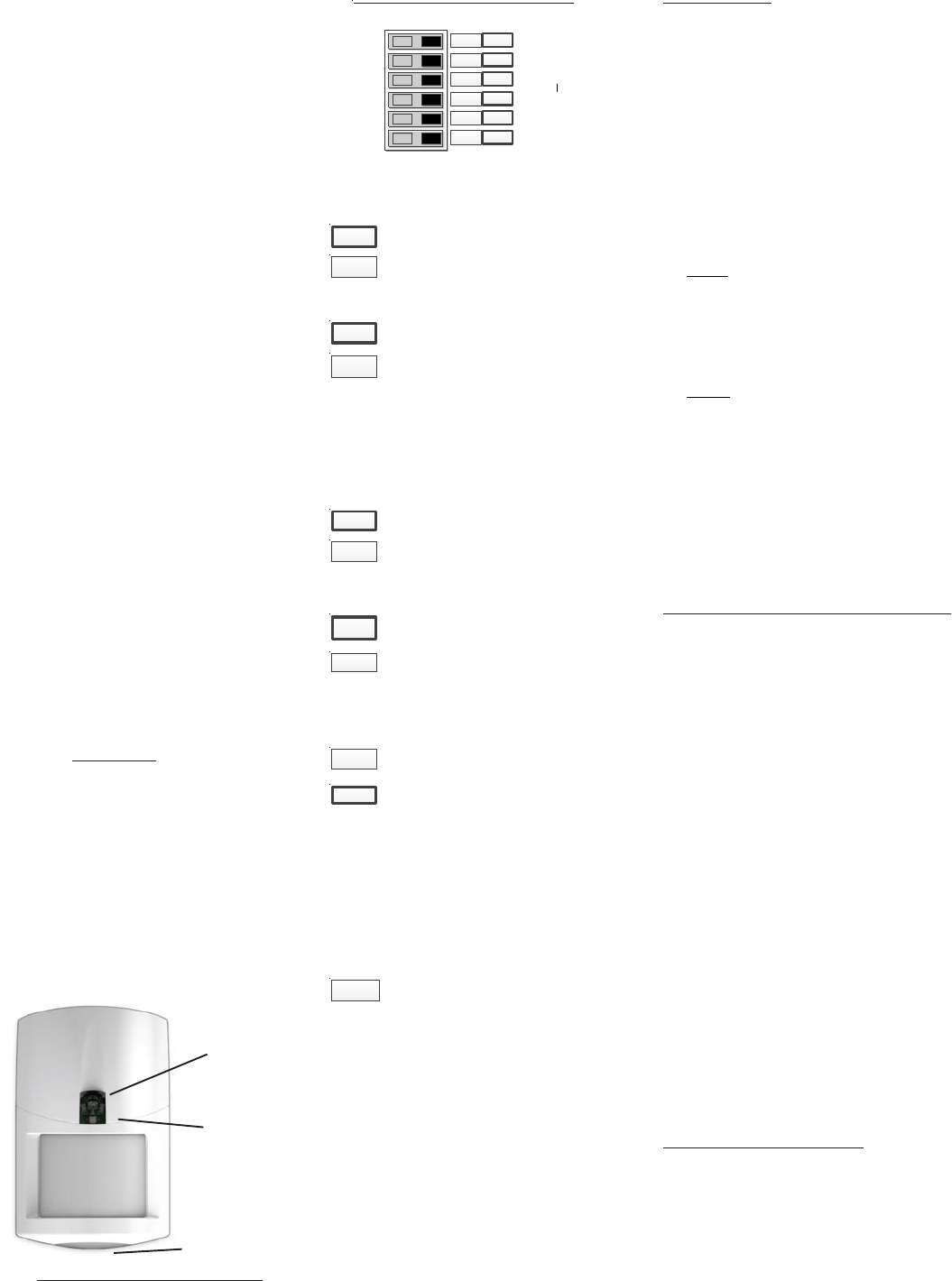
PULSE COUNT
RANGE
SLEEP CYCLE
SEC/CONV. LED
RF ACK. LED
- Future use -
ON OFF
Factory Default Settings Outlined in BOLD
6
5
4
2
3
1
3 - 4 1 - 2
HI LO
SH LG
YES NO
NO YES
N/A N/A
PULSE COUNT (Switch 6)
Sensor must detect 1 or 2 events in the
coverage area before an alarm is created.
FUTURE (Switch 1)
Sensor must detect 3 or 4 events in the
coverage area before an alarm is created.
RANGE (Switch 5)
Sensor is set for the shorter detection range
(approximately 39ft.)
Sensor is set for the longest detection range
(approximately 49ft.)
To extend battery life, a mandatory sleep cycle (2 time
settings) begins after each alarm transmission. After
the Sleep Cycle expires, there must be ~8 seconds of
quiet (no movement) before the sensor will be allowed
to detect and send another radio transmission.
Long (120 secs.) Until this timer expires the
sensor cannot transmit another event.
SECURITY/CONVENIENCE LED (Switch 3)
This switch is not currently utilized.
Short (30 secs.) Until this timer expires the
sensor cannot transmit another event.
Sec/Convenience LED is NOT ENABLED
except for the Walk Test Mode.
Sec/Convenience LED is ENABLED for
other functions besides just the Walk Test
Mode. See back page for details.
RF ACK "Alarm" LED (Switch 2)
RF ACK LED (Green/Red) is NOT ENABLED
except during the Walk Test Mode.
RF ACK LED (Green/Red) is ENABLED. It
should blink Green or Red after each detect.
3 - 4
1 - 2
LO
HI
LG
SH
NO
YES
N/A
SLEEP CYCLE (Switch 4)
YES
NO
4. SENSOR ENROLLMENT FROM ELKRP
4.1 Launch the ElkRP PC software and open the
desired Customer Account file.
4.2 Click the "+" next to Zones (Inputs) to expand the
view. Look to see if there are any existing wireless
zone groups. If there are none then it will be
necessary to add or create a new group. To create
a wireless group, right click on Zones (Inputs) and
click New Wireless Zones. Place a check mark
in the box to be added, starting with Group 2). Click
OK. Repeat if more wireless groups are required.
NOTE: The M1 Control requires all expanded
zones to be defined in groups of 16. E.G. Zones
17-32 = Group 2, zones 33-48 = Group 3, etc. And
it requires the M1XRFTW Two-Way Transceiver
to always be enrolled as the first expander
(databus address 2). For this reason, the first
group of wireless sensors must be defined as
group 2. M1 allows a maximum of 144 wireless
zones, therefore the last potential wireless
zone will be Zone 160. So, If a large number
wireless zones is ever anticipated, it would be
a good idea to avoid conflict with any future
Hardwired Zones in the 17 to 160 range by NOT
enrolling any Hardwired Zone Expanders
(M1XIN) at data bus addresses below 10.
4.3 Double click on Wireless - Group _ (the group just
added) and double click one zone at a time to define
the Zone Name, Definition, Type, Attributes, etc.
4.4 The next step is to enter the sensor's TXID and the
other wireless setup data. This may be done
directly from each zone definition screen (click the
Wireless Setup button) OR from the separate
Wireless Setup menu accessed from the folders
column.
4.5 Place a check mark in the Enabled box.
4.6 Set Supervision type to "1" (Normal Supervision)
for the 6030 Sensor. A setting of "0" means the
control will not expect a supervisory check-in from
the sensor. For additional details refer to Supervision
on the previous page.
4.7 Skip past the block titled: This device is a PIR (auto
restore). Do Not Enable. The 6030 PIR will transmit
a restore after each alarm as long as all functions
return to normal. This M1 option is for other
supported brands of wireless PIRs that do not
transmit restorals.
4.8 Skip to the TXID box and enter the Sensor TXID that
is printed on the small label attached to the sensor.
4.9 Skip to the LOOP box and enter a 2.
4.10 Click Save. Repeat the entire step 4 for each
additional Wireless Zone and Sensor.
5. DIP SWITCH OPTION SETTINGS
Green = Sensor transmitted and received a positive
ACK (acknowledgment) from the Control/
Transceiver.
Red = Sensor transmitted (or attempted to) but it did
not receive an ACK (acknowledgment) from
the Control/Transceiver.
Creep Zone
"Lookdown"
Security/
Convenience
(White) LED
RF ACK
(Green/Red) LED
Figure 6. Front View of Sensor
Figure 7. DIP Switches

Page 4 ELK-6030 PIR Installation Manual
LIMITATIONS
While the 6030 Passive Infrared (PIR) Motion Detector
is a highly reliable intrusion detection device, it does not
offer guaranteed protection against burglary. Any
intrusion detection device is subject to compromise or
failure to warn for a variety of reasons:
PIR Detectors can only detect movement within a
specific coverage area as diagrammed in this manual.
To detect movement, the PIR Detector senses the
infrared energy that is emitted from an intruder moving
across the sensor's field of view.
PIR Detectors do not provide volumetric area protection.
They create multiple beams of protection. Intrusion can
only be detected in unobstructed areas covered by
those beams.
PIR Detectors cannot detect motion or intrusion that
takes place behind walls, ceilings, floors, closed doors,
glass partitions, glass doors, or windows.
The radio transceiver only provides communications.
It does not have anything to do with detecting motion.
LIMITED WARRANTY
The 6030 Wireless PIR Sensor is warranted to be free
from defects and workmanship for a period of 2 years
from date of manufacture. Batteries used with wireless
devices are not warranted. Elk makes no warranty,
express or implied, including that of merchantability or
fitness for any particular purpose with regard to batteries
used with wireless devices. Refer to Elk’s website for
full warranty statement and details.
PO Box 100 3266 US Hwy 70 West
Hildebran, NC 28637
828-397-4200 828-397-4415 Fax http://www.elkproducts.com
Printed in USA
L645 Rev. A 11/19/12
A deluxe 90° swivel bracket may be purchased and used
in lieu of the standard swivel bracket. This bracket has
a short extended arm and allows the sensor to be aimed
at up to a 90° offset from the wall or base. This bracket
also allows the sensor to be drop mounted from a ceiling.
OPTIONAL DELUXE 90° SWIVEL MOUNT
ANTI-TAMPER SWITCH
This switch detects the separation of the front housing
from the backplate. When this is tripped a signal is
transmitted to the control/transceiver, causing the
associated zone to become violated. Snapping the front
housing back onto the backplate transmits a restoral.
Note: Tamper can be ignored for any sensor (zone)
by setting its Zone Type to 1=Normally Closed.
FUNCTIONAL 'SYSTEM' TESTING
A system test should be done by physically walking
across the 6030 coverage pattern while the system is
fully armed. NOTE: Allow time for the Sleep Cycle Timer
to expire before testing. Always notify the Central
Monitoring Station prior to performing any testing.
BATTERIES
The 6030 battery compartment holds 2 x CR123A Lithium
batteries. The estimated service life of these batteries
is 5 to 7 years in typical residential usage with the Sleep
Cycle set to LG (Long),
Battery #1 (lower) is supervised for low voltage. When
the sensor detects the voltage has reached 2.6 VDC or
less (under load), a Sensor Low Battery trouble will be
transmitted to the control/transceiver. This trouble will
be attached to all future transmissions until fresh new
batteries are installed. Battery #1 is the primary power
source for all critical functions (motion detect and radio
transmission) of the 6030 sensor.
Battery #2 (upper) is not-supervised for low voltage.
This battery is a secondary (reserve) power source for
the 6030 critical functions, but it is the primary (sole)
power source for the White Security/Convenience LED.
The White Security/Convenience LED will not operate
without a good battery installed in Battery #2 location.
We strongly recommend installing a battery in both
locations. These 2 batteries are electrically isolated in
such a way that critical functions of the 6030 can draw
power either battery, but the White Convenience LED
can only draw power from Battery #2.
To clear a sensor low battery trouble condition, install
new batteries and then trip the sensor a couple of times.
This clears the low battery trouble and sends "all good"
to the control/transceiver.
Caution: Excessive use of the White Security/
Convenience LED will rapidly reduce the life of
Battery #2. More importantly, because the 6030
sensor is able to tap into Battery #2 for secondary
power, any reduction of its life naturally reduces
the overall operational life of the sensor. If maximum
sensor operational life is the top priority, the
Security/Convenience LED may be disabled by
turning DIP Switch #3 OFF.
BATTERY REPLACEMENT
Use only CR123A 3V Lithiums. Replace both batteries
at the same time. If possible, both batteries should
have the same manufactured date code. Replacements
can be obtained from Alarm Distributors.
1. Remove sensor from back housing.
2. Observe correct polarity when installing the new
batteries. Do not bend or damage the metal battery
holder contacts. Approved Batteries: 3V Lithium -
Panasonic CR123A, Duracell DL123A, Varta CR123A,
Sanyo CR123A
3. Re-test sensor operation with the control.
BATTERY WARNING: Risk of fire, explosion
and burns. Do not attempt to recharge or
disassemble. Do not incinerate or expose to
heat above 212° F (100° C). Dispose of used
batteries properly. Keep away from children.
ACTIVATING THE WHITE
SECURITY/CONVENIENCE LIGHT
TM
This high-intensity LED projects light out the front of the
sensor. There are five (5) modes of operation: 1)Flash
during an audible alarm activation. 2)On Solid when
motion is detected and either the control is armed AWAY
mode or when output 4 is On. 3) Flash on command from
control. 4)On Solid by command from control. 5)Quick
blip in walk test mode when motion is detected.
Note: For all conditions EXCEPT Walk Test, the
white LED may be totally disabled by DIP Switch #3.
1) Flash upon audible alarm activation
If DIP Switch #3 is ON, ANY audible alarm activation
from the Control (not Silent 24hr Police) will cause the
White LED to flash. This flash will continue until either
the Alarm Cutoff timer expires, the Control is disarmed,
or Battery #2 (the upper battery) is drained.
Note: The 6030 reacts to two-way wireless commands
from the M1 Control. Please understand that it can
take several seconds for the 6030 to receive a
command. The time delay is typically 8 seconds or
less. Be prepared for this delay during testing and
operation. Do not expect instantaneous reaction.
Activating the white LED via ElkRP Rules
The white LED may be controlled via ElkRP Rules using
M1 Outputs 4, 5, & 6. These outputs do not appear on
the M1 board and are generally only used as rule flags.
The 6030 detects the state of these 3 outputs and
performs as follows:
2) On Solid if Motion Detected while armed to Away
Any motion detected while the control is armed to AWAY
mode will result in the white LED turning On for approx.
18 seconds. {DIP Switch #3 must be ON}
OR
On Solid if Motion Detected and Output 4 is on
Any motion detected while M1 Output 4 is On will cause
the white LED to turn On for approx. 18 seconds.
Additional motion can restart this time. Output 4 can be
turned On at a specific time, date, or condition using an
ElkRP rule. E.G. "When Sunset - Then Turn Output 4
On." Use another ElkRP rule to turn Output 4 Off when
this LED action is no longer desired. E.G. "When Sunrise
- Then Turn Output 4 Off."
3) Flash - on command [M1 Output 5]
When the 6030 sees M1 Output 5 turn On it will start the
white LED flashing for approx. 18 seconds. Output 5
can be turned On at a specific time, date, or condition
using an ElkRP rule. E.G. "When 5:30PM (Close Time?)
- Then Turn Output 5 On for 15 seconds." (15 seconds
is an arbitrary value) The crucial point is that Output 5
must first be turned Off before it can again be turned
back On to restart the white LED Flash.
Solid On - on command [M1 Output 6]
When the 6030 sees M1 Output 6 turn On it will turn the
white LED On Solid for approx. 18 seconds. Output 6
can be turned On at specific time, date, or condtion
using an ElkRP rule. E.G. When Entry Delay Starts
- Then Turn Output 6 On for 15 seconds." (15 seconds
is an arbitrary value) The crucial point is that Output 6
must first be turned Off before it can be turned back
On to restart the white LED Solid On.
Examples of Rules for the Security/Convenience Light:
Whenever Sunset
Then Turn On Output 4 On.
Whenever Sunrise
Then Turn Off Output 4 Off.
Whenever Time is 6:00pm (e.g. dinner time)
Then Turn On Output 5 for 15 seconds.
Whenever Entry Delay Starts
Then Turn On Output 6 for 15 seconds.
NOTES: DIP Switch #3 allows each individual 6030
sensor to be excluded from the above operations.
FCC COMPLIANCE STATEMENT:
This device complies with Part 15 of the FCC Rules.
Operation is subject to the following two conditions:
(1) this device may not cause harmful interference,
and (2) this device must accept any interference
received, including interference that may cause
undesired operation.
Part # Description FCC ID #
ELK-6030 Wireless PIR Sensor TMA ELK-6030
NOTE: ELK PRODUCTS IS NOT RESPONSIBLE
FOR ANY CHANGES OR MODIFICATIONS NOT
EXPRESSLY APPROVED BY THE PARTY
RESPONSIBLE FOR COMPLIANCE. SUCH
MODIFICATIONS COULD VOID THE USER’S
AUTHORITY TO OPERATE THE EQUIPMENT.
Backplate
Deluxe 90°
Swivel
Bracket
Locking
Disc
Figure 8. Deluxe 90° Swivel Bracket
(Separate purchase P/N: ELK-603022)