Elk ELK-M1XRFTWM ELK M1XRFTWM Wireless Transceiver User Manual Manual
ELK Products, Inc. ELK M1XRFTWM Wireless Transceiver Manual
UserManual.wiki
>
Elk
>
ELK M1XRFTWM User Manual
Manual
Navigation menu
Upload a User Manual
Namespaces
Wiki Guide
HTML
PDF
Info
Views
User Manual
Discussion / Help
Navigation


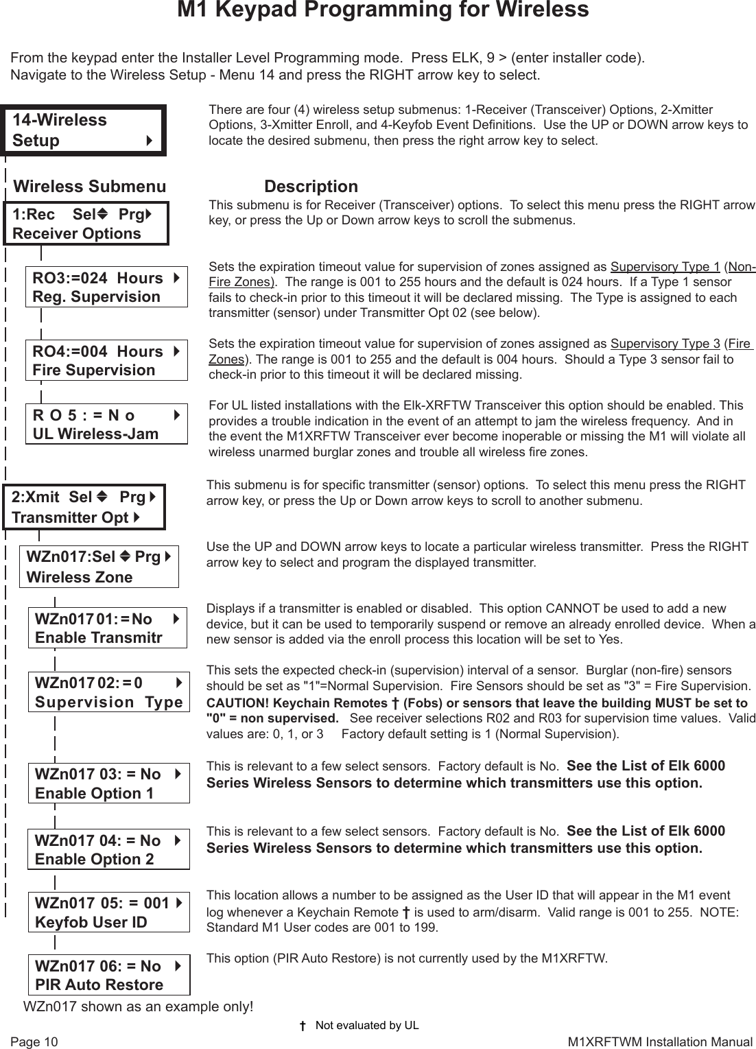
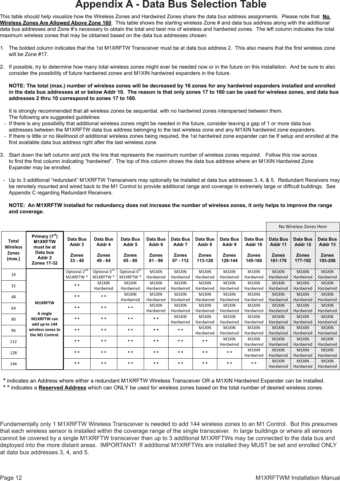
![M1XRFTWM Installation Manual Page 11Select the zone for the new transmitter (sensor) by entering the three (3) digit zone number OR by scrolling to the zone number using the UP and DOWN arrow keys. NOTE: If a transmitter is already enrolled for this zone the display will resemble 3c below. Otherwise, it will display "TransmitrToLrn".Press the RIGHT arrow key to select and program the zone.As this message is displayed the M1 will speak: "Press Transmitter Button for Zone XXX". Go to the transmitter (sensor) and execute the enroll process according the sensor instructions. In most cases this requires inserting the battery. If successful the keypad will chime and M1 will speak: "[Zone Number/Name] Enrollment." Refer to step 3c below.The TXID of the newly enrolled transmitter (sensor) will momentarily display. Rapid Enroll will then auto-advance to the next zone (step 3b) to permit sequential enrollment of transmitters. Press the ELK key twice to exit the enrollment after all new sensors have been enrolled.DELETING A WIRELESS SENSOR - To delete an existing sensor navigate to option "WZnxxx 01" and select "No". NOTE: Manually setting the Loop to 0 will also delete a sensor. SETTING THE LOOP #. Refer to the "Elk 6000 Series Wireless Sensors" chart for more infor-mation on the loop setting of each sensor. For single internal reed sensors the Loop # setting will be 2. It is VERY IMPORTANT to follow the directions outlined in the referenced chart and set the Loop # correctly. From step 3a press the Keypad LEFT arrow marked "HW". The TXID in decimal notation will display on the lower left. Press the RIGHT arrow to move the cursor over to Loop =. Enter 1, 2, or 3 according to the sensor instructions. Refer to the "Elk 6000 Series Wireless Sensors" for more information. This submenu is used to manually enroll transmitters (sensors). To select this menu press the RIGHT arrow key, or press the Up or Down arrow keys to scroll submenus.This submenu is used to program the operation or "action" for Keychain Remote † (FOB) but-tons. Each button can be assigned one of six (6) separate operations as explained below. To select this menu press the RIGHT arrow key. Press the UP or DOWN arrow keys to select a key (button) 1 to 8. Some models may not support all the programmable buttons. The event or operation for each button is set by a four (4) digit event code. The range of event codes is 0000 to 0030 See M1 Installer Manual, Appendix A, Event Codes. Factory default = Only keys (buttons) 1 and 2 have a default setting. Key (Button) & Symbol M1 Factory Default Event & OperationKey1 - Lock Event=0027 - KeyMomAway (Arm the Control)Key2 - Unlock Event=0029 - KeyMomDisarm (Disarm the Control)Key3 - i Status Inquiry Event=0000 - unprogrammed See NOTE 1 belowKey4 - Red Triangle Event=0000 - unprogrammed See NOTE 2 belowNOTE 1: Key (button) 3 on a 6010 Keychain Remote ALWAYS performs a system status Inqui-ry when pressed momentarily. This same key may be pressed and held for four (4) seconds to activate M1 programmable Key3 event. Factory default is 0000 (do nothing)NOTE 2: Key (button) 4 on a 6010 Keychain Remote REQUIRES a press and hold for two (2) full seconds in order to activate M1 programmable Key4 event. This can be any event, howev-er the most common use is for emergency panic (Police Panic event 0023 or 0024). Factory default is 0000 (do nothing)DOUBLE KEY (BUTTON) PRESSESM1 programmable Key7 event may be triggered by pressing the top 2 keys (buttons) together for ~3 seconds, and Key8 event may be triggered by pressing and holding the bottom 2 keys.SWAPPING THE KEY (BUTTON) FUNCTIONSThe M1 programmable keychain events are GLOBAL for all units. While it is not possible to fully customize the keys for multiple persons, it is possible to swap keys 1,2,3,4 to become keys 5,6,7,8. This allows 2 different remotes or people to activate different events. Enable Option 1 from Menu 14, sub-menu 2:Xmit Transmitter Opt. WZone = 17 shown as example3b3c3d3a† Not evaluated by UL † WZone = xxx Push TransmiterButtonWZone = 017 HW lTransmitrToLrn r3:Learn Selb Prg rWirelessTransmtrWZone = xxx Enrolled ABCDE14:KeyfobSelbPrgrEvent DenitionWZone = xxx HW l A0000000 Loop=0Key=1 Evt=0000 r[name of event]Key=2 Evt=0000 r[name of event]Key=3 Evt=0000 r[name of event]Key=4 Evt=0000 r[name of event]Key=5 Evt=0000 r[name of event]Key=6 Evt=0000 r[name of event]Key=7 Evt=0000 r[name of event]Key=8 Evt=0000 r[name of event]](https://usermanual.wiki/Elk/ELK-M1XRFTWM/User-Guide-3083082-Page-11.png)