Elk ELK-M1XRFTW ELK M1 INTERFACE TRANSCEIVER User Manual M1XRFTW Elk Wireless Receiver pmd
ELK Products, Inc. ELK M1 INTERFACE TRANSCEIVER M1XRFTW Elk Wireless Receiver pmd
UserManual.wiki
>
Elk
>
ELK M1XRFTW User Manual
Users Manual
Navigation menu
Upload a User Manual
Namespaces
Wiki Guide
HTML
PDF
Info
Views
User Manual
Discussion / Help
Navigation
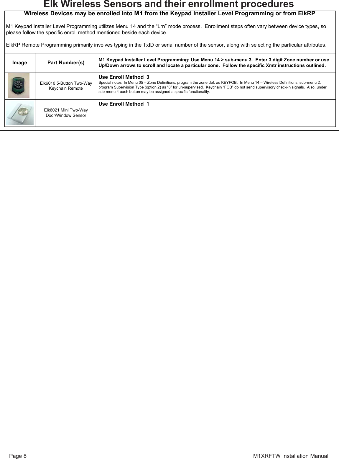
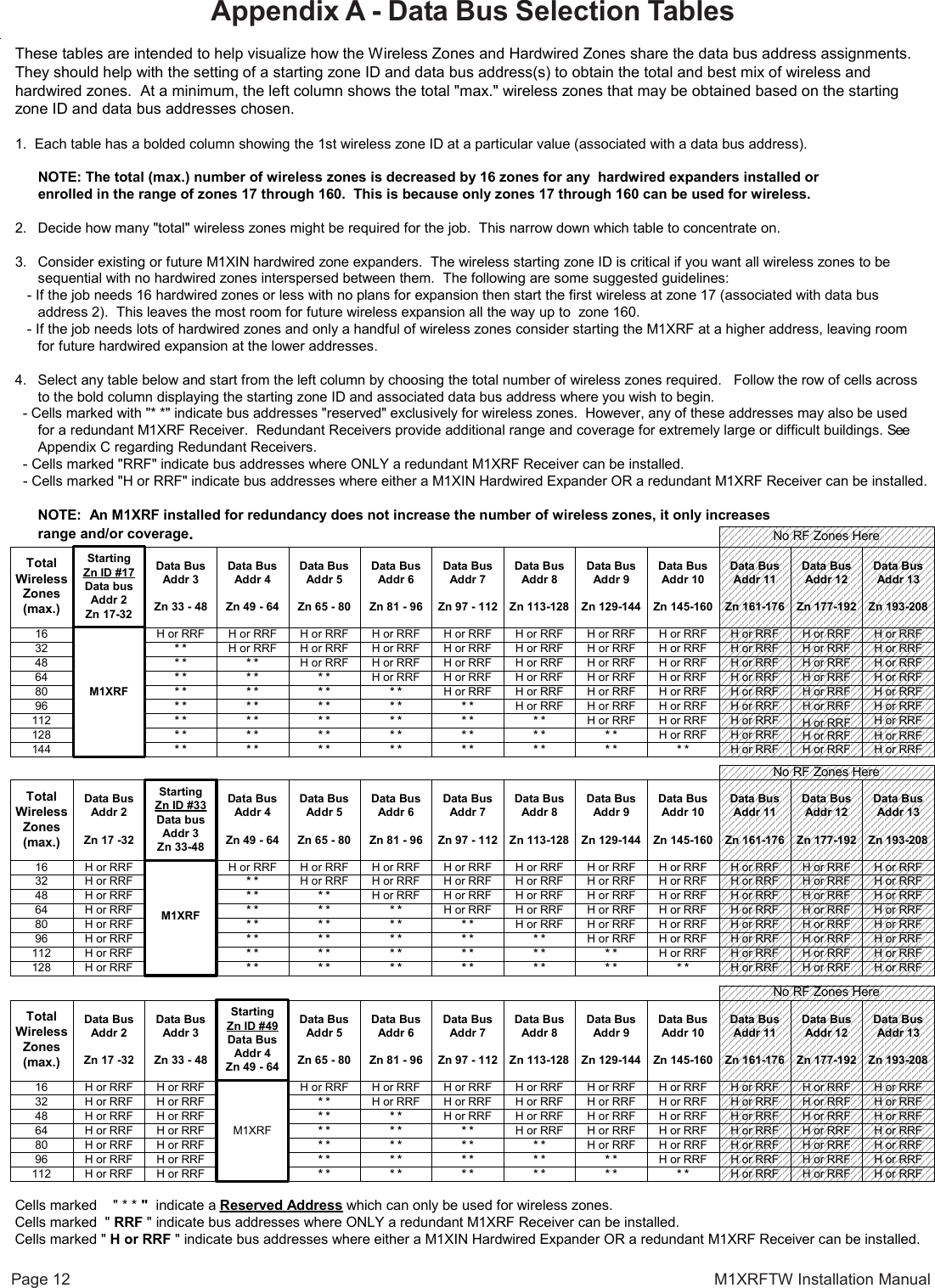
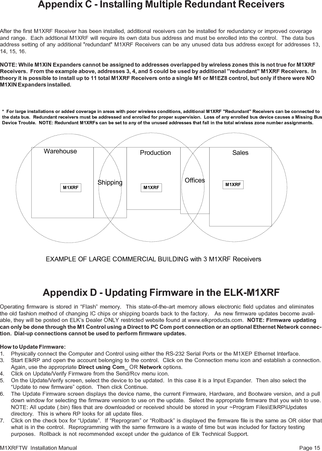
![Page 10 M1XRFTW Installation ManualWireless Submenu DescriptionThis submenu is for Receiver options. To select this menu press the RIGHT arrow key, orpress the Up or Down arrow keys to scroll the submenus.Rec. Option R03 is the time value for zones programmed as Supervisory Type 1 or "Non-Fire"transmitters (see Xmit Transmitter Opt 02 below). The range is 001 to 255 hours. If a Type 1sensor fails to check-in prior to the expiration of this time it is considered "missing". Factorydefault setting is 024 hours. NOTE: A value less than 4 hours is NOT RECOMMENDED!Rec. Option R04 is the time value for zones programmed as Supervisory Type 2 or "Fire"transmitters (see Xmit Transmitter Opt 02 below). The range is 001 to 255 hours. If a Type 2sensor fails to check-in prior to the expiration of this time it is considered "missing". Factorydefault setting is 004 hours. NOTE: A value less than 4 hours is NOT RECOMMENDED!This submenu is for specific transmitter options. Some options are not applicable to thismodel of the M1XRF. To select this menu press the RIGHT arrow key, or press the Up orDown arrow keys to scroll the submenus.Use the UP and DOWN arrow keys to locate a particular wireless transmitter. Press theRIGHT arrow key to select and program the displayed transmitter.Displays whether a transmitter is enabled or disabled. This option CANNOT be used to add anew device, but it can be used to temporarily suspend an already enrolled device. The enrollprocess must be used to add a new transmitter, after which this location will be set to Yes.Supervision type sets the expected check-in interval of a sensor. KeyChain Remotes (Fobs)or devices which may leave the building program set this "0" = non supervised. BurglarSensors should have this option set as "1"=Normal Supervision. Fire Sensors should havethis option set as "3" = HI Supervision. See receiver selections R02 and R03 for supervisiontime values. Valid values are: 0, 1, or 3 Factory default setting is 1 (Normal Supervision).Pertains only to certain types of Transmitters. For KeyChain Remotes setting this option toYes converts buttons 1,2,3,4 to be instead buttons 5,6,7,8. Default is No. See list ofcompatible Transmitters to determine which (if any) transmitters use this option.Pertains to transmitters with Ext. contact terminals. Setting this to Yes permits Open Circuit[N/O] switches. If set to No then only Closed Circuit [N/C] switches may be connected.Default is No. See list of compatible Transmitters to determine which (if any)transmitters use this option.Used to program the User ID which will be logged when a Keychain Remote assigned to thiszone is used to arm of disarm. Valid range is 001 to 255. Numbers 001 to 199 mirror keypaduser codes. Note: Open/Close reports may be programmed for every User code.Not used. If set to Yes the zone is auto-restored to normal in 8 seconds with no restoralsignal from the transmitter.1:Rec Selb PrgrReceiver OptionsThere are four (4) wireless setup submenus: 1-Receiver Options, 2-Xmitter Options, 3-XmitterEnroll, and 4-Keyfob Event Definitions. Use the UP or DOWN arrow keys to locate the desiredsubmenu, then press the right arrow key to select.14-WirelessSetup r† Not evaluated by UL2:Xmit Sel b PrgrTransmitter Opt rWZn017 04: = No rEnable Option 2WZn017 01: = No rEnable TransmitrWZn017 02: = 0 rSupervision TypeWZn017 03: = No rEnable Option 1RO3:=024 Hours rReg. SupervisionWZn017:Sel bPrgrWireless ZoneWZn017 05: = 001 rKeyfob User IDWZn017 06: = No rPIR Auto RestoreRO4:=004 Hours rFire SupervisionFrom the keypad enter the Installer Level Programming mode. Press ELK, 9 > (enter installer code).Navigate to the Wireless Setup - Menu 14 and press the RIGHT arrow key to select.Programming via Keypad< continued on next page >WZn017 shown as an example only!](https://usermanual.wiki/Elk/ELK-M1XRFTW/User-Guide-1519520-Page-10.png)
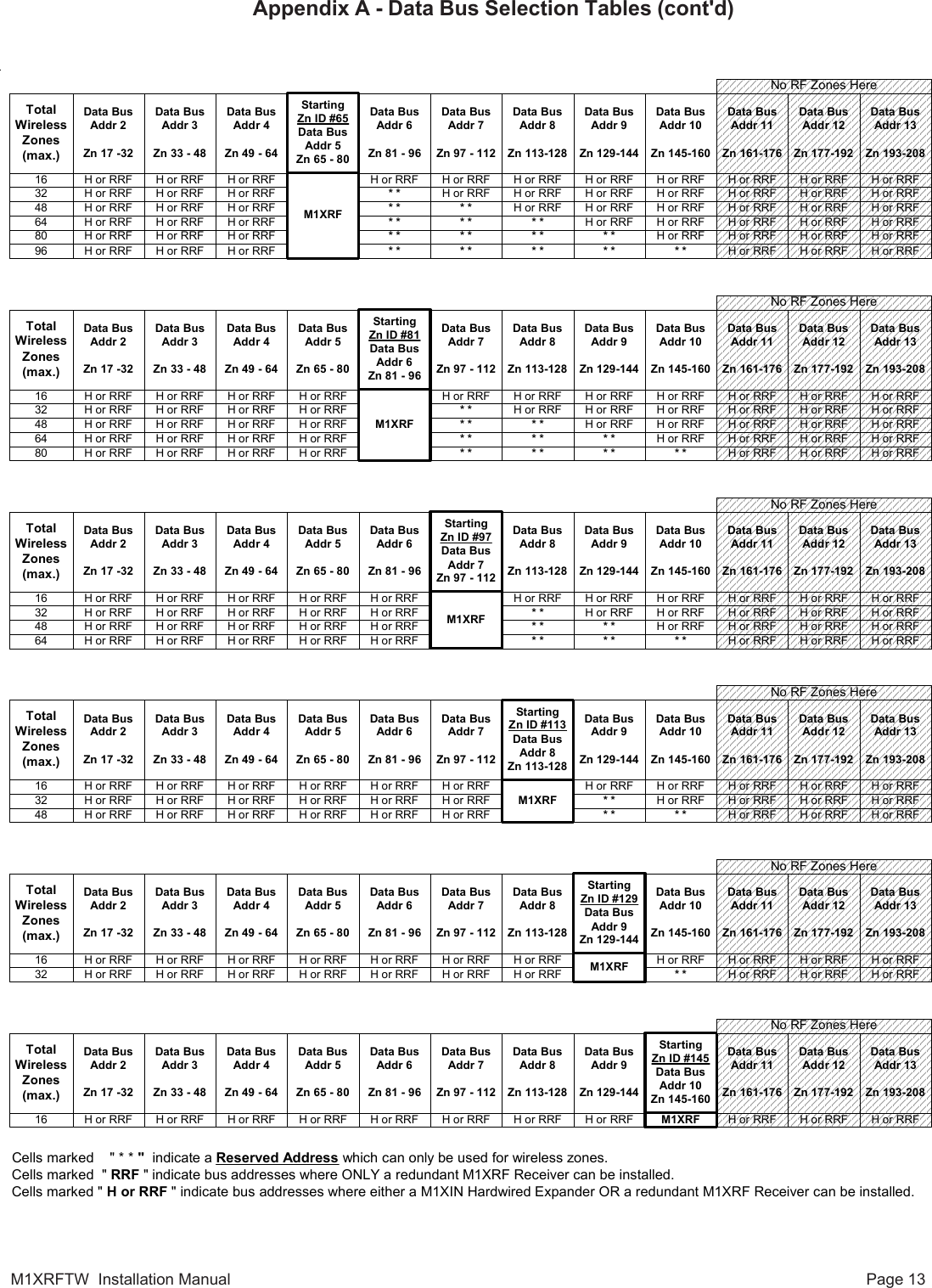
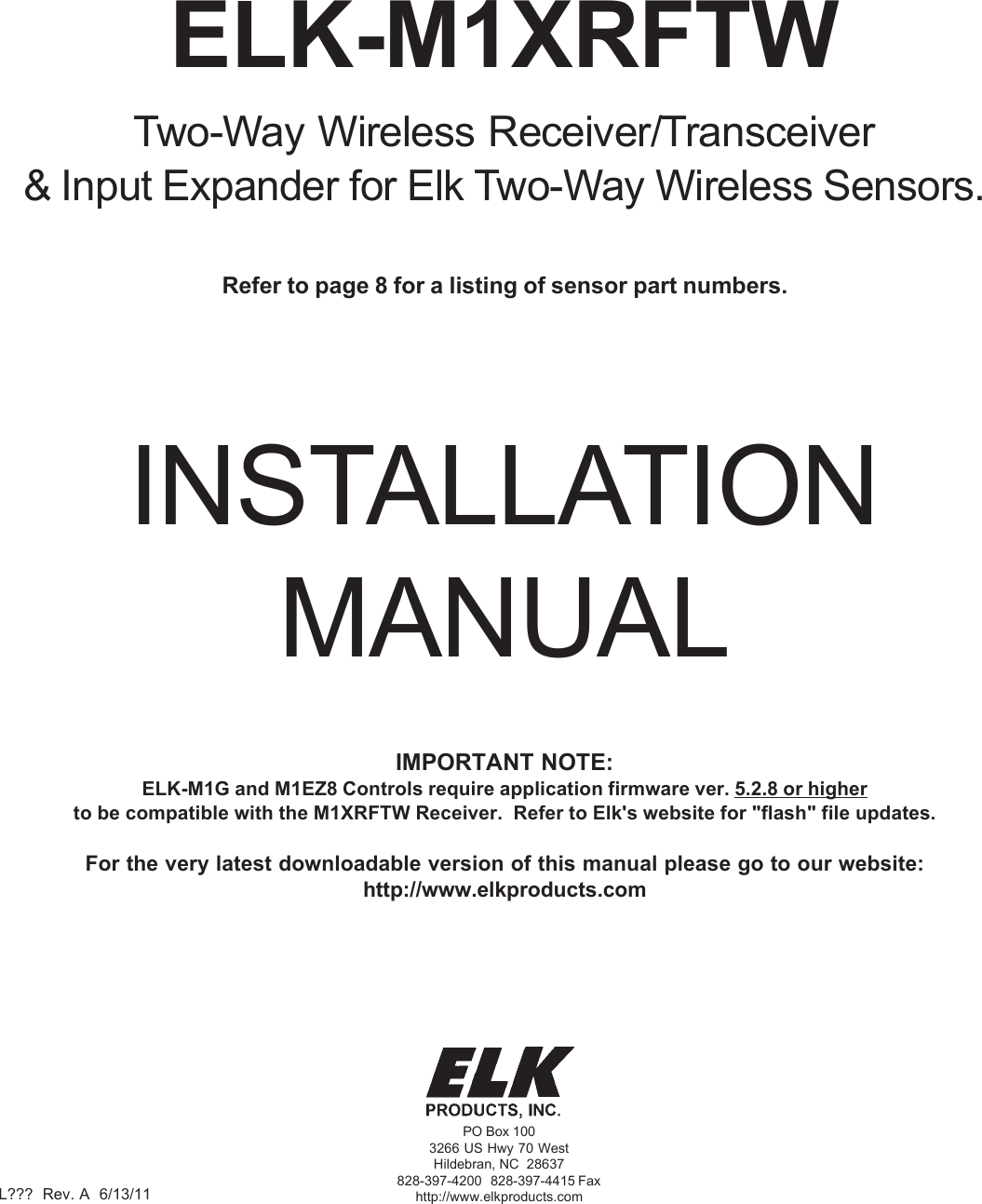
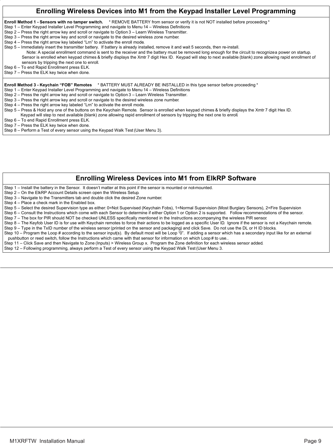
![M1XRFTW Installation Manual Page 11Select the zone to enroll a new transmitter by entering the three (3) digit zone number OR byscrolling to the zone number using the UP and DOWN arrow keys. NOTE: If a transmitter isalready enrolled for this zone the display will resemble 3c below. Otherwise, it will display"TransmitrToLrn".Press the RIGHT arrow key to select and program that zone.This message will display and the M1 will speak: "Press Transmitter Button for Zone XXX",UNLESS a transmitter is already enrolled (see below). Proceed to the transmitter and executethe enroll process. I.E. Insert the batteyr or press the tamper button, etc. If successful thekeypad will chime and M1 will speak: "[Zone Name] Enrollment."Displays the zone number and ID of the enrolled transmitter. NOTE: After a new transmitter isenrolled this display advances to the next zone number and the M1 speaks "Press Transmit-ter Button for Zone xxx." This permits rapid enrollment of additional transmitters in sequentialorder. When enrollment is complete press the ELK key twice to exit the enrollment.IMPORTANT! To delete or replace an existing transmitter navigate to transmitter option"WZnxxx 01" and select "No". This will disable the existing transmitter.Pressing the LEFT arrow marked "HW" at step 3a will produce display 3d. The left numberrepresents the transmitter ID in decimal notation. Press the RIGHT arrow key to move cursorover to Loop. For most Elk transmitters the Loop should automatically be set to "0". However,for a sensor that offers both an internal reed switch PLUS external inputs for an externalcontact the Loop would need to be changed to "1" in order for the external contact to befunctional.WZone = xxx PushTransmiterButtonWZone = 017 HW lTransmitrToLrn r3:Learn Selb PrgrWirelessTransmtrThis submenu is used for manually enrolling transmitters. To select this menu press theRIGHT arrow key, or press the Up or Down arrow keys to scroll submenus.This menu is used to program the operation or "action" for Keychain Remote (FOB) buttons.Each button can be assigned one of six (6) separate operations as explained below. Toselect this menu press the RIGHT arrow key.Press the UP or DOWN arrow keys to select a key (button) 1 to 8. Some keys (buttons) maynot be usable depending on the model. The definition or operation is programmed using afour (4) digit event code derived from the Zone Definitions table located in the M1 InstallationManual. The range is 0000 to 0030 See M1 Installer Manual, Appendix A, Event Codes.By factory default the M1 programming is assigned to the following keyfob buttons withprinted symbols. Key # / (ICON) M1 Default Value OperationKey 1 / Lock Event=0027 KeyMomAway (Arm the Control)Key 2 / Unlock Event=0029 KeyMomDisarm (Disarm the Control)Key 3 / Light Event=0000 "No default function"Key 4 / Asterisk Event=0000 "No default function"Center Key on Elk6010 KeyChain Remote is not programmable. It is permanently set tofunctin as a Information "I" key which can query the Elk Receiver for StatusDOUBLE KEY PRESSESPressing the Lock and Unlock buttons together momentarily will trigger the event assignedto Key 7. The M1 Default Event Value is "0000" or "No default function".Pressing the Light and Asterisk buttons together momentarily will trigger the event assignedto Key 8. The M1 Default Event Value is "0000" or "No default function".WZone = 17 shown as example only!WZone = xxxEnrolled ABCDE1Key=1 Evt=0000r[name of event]Key=2 Evt=0000r[name of event]Key=3 Evt=0000r[name of event]Key=4 Evt=0000r[name of event]Key=5 Evt=0000r[name of event]Key=6 Evt=0000r[name of event]Key=7 Evt=0000r[name of event]Key=8 Evt=0000r[name of event]4:KeyfobSelb PrgrEvent DefinitionWZone = xxx HW lA0000000 Loop=03b3c3d3a](https://usermanual.wiki/Elk/ELK-M1XRFTW/User-Guide-1519520-Page-11.png)