Elk ELK-M1XRFTW ELK M1 INTERFACE TRANSCEIVER User Manual M1XRFTW Elk Wireless Receiver pmd
ELK Products, Inc. ELK M1 INTERFACE TRANSCEIVER M1XRFTW Elk Wireless Receiver pmd
Elk >
Users Manual

ELK-M1XRFTW
Two-Way Wireless Receiver/Transceiver
& Input Expander for Elk Two-Way Wireless Sensors.
Refer to page 8 for a listing of sensor part numbers.
INSTALLATION
MANUAL
L??? Rev. A 6/13/11
PO Box 100
3266 US Hwy 70 West
Hildebran, NC 28637
828-397-4200 828-397-4415 Fax
http://www.elkproducts.com
IMPORTANT NOTE:
ELK-M1G and M1EZ8 Controls require application firmware ver. 5.2.8 or higher
to be compatible with the M1XRFTW Receiver. Refer to Elk's website for "flash" file updates.
For the very latest downloadable version of this manual please go to our website:
http://www.elkproducts.com

Page 2 M1XRFTW Installation Manual
Table of Contents
General Installation and Setup ..................................................................................................... 4
Setting the M1XRF Data Bus Address and the Starting Wireless Zone ID ............................................... 5
Data Bus Enrollment:: .............................................................................................................................. 6
Data Bus Address Switches..................................................................................................................... 6
Operation ....................................................................................................................................... 7
Diagnostic LEDs: ..................................................................................................................................... 7
What makes the Elk Two-Way technology different from existing "older" wireless technology? .............. 7
Elk Wireless Sensors and their enrollment procedures ............................................................. 8
Programming via Keypad ........................................................................................................... 10
Appendix A - Data Bus Selection Tables ................................................................................... 12
Appendix B - Examples of Zone Configurations ...................................................................... 14
Appendix C - Installing Multiple Redundant Receivers ............................................................ 15
Appendix D - Updating Firmware in the ELK-M1XRF ............................................................... 15
FEATURES:
•Adds up to 144 individual wireless zones (sensors/points)
•Operates from the 4 wire RS485 Data Bus
•Multiple Receivers (up to 11) may be connected to a single M1 or M1EZ8 Control for redundancy and greater coverage
•Flash Memory allows field updating of operating Firmware
•Compatible with Elk complete line of Two-Way Wireless Sensors.
SPECIFICATIONS:
•Operating Frequency: 902 Mhz to 928 Mhz
•Transmission Duration (active on-time): 50 ms
•Sensitivity: >105 dbm
•Operating Temperature: 0 to +120 degrees F
•Operating Voltage: 12 Volts D.C.
•Current Draw: 25mA Receiving, 85mA Transmitting
•Indoor Range: 300 to 500 ft. ** line of sight
** Laboratory tests have achieved greater distances, however walls and metal objects generally reduce actual operating range.
FCC COMPLIANCE STATEMENT:
This device complies with Part 15 of the FCC Rules. Operation is subject to the following two conditions:
(1) this device may not cause harmful interference, and
(2) this device must accept any interference received, including interference that may cause undesired operation.
NOTE: ELK PRODUCTS IS NOT RESPONSIBLE FOR ANY CHANGES OR MODIFICATIONS NOT EXPRESSLY APPROVED BY THE PARTY RESPONSIBLE
FOR COMPLIANCE. SUCH MODIFICATIONS COULD VOID THE USER’S AUTHORITY TO OPERATE THE EQUIPMENT.
Part Number Description FCC ID Number
ELK-M1XRFTW M1 Two-Way Receiver FCC ID: TMA ELK-M1XRFTW
ELK-6010 KeyChain Remote "FOB" FCC ID: TMA ELK-6010
ELK-6021 Mini Door & Window Sensor FCC ID: TMA ELK-6021
M1XRFTW Installation Manual Page 3
OVERVIEW
The "TW" model of the ELK-M1XRF Wireless RF Receiver (part # ELKM1XRFTW) allows an ELK-M1 and ELK-M1EZ8
Controls to accept Elk's complete line of Two-Way Wireless Sensors. Refer to the list of available transmitters in this manual.
Including this new Elk Two-Way Receiver, Elk now produces three (3) different models of wireless receivers for the M1 Control.
One is for Elk sensors (M1XRFTW), one is for GE sensors (M1XRF2G), and one is for Honeywell sensors (M1XRF2H).
Regardless of the receiver model, they each attach directly to the M1 via the four (4) wire Keypad Data Bus. And they enroll
and integrate in much the same way as a hardwired zone expander, with the exception that a single M1XRF can handle up
to 144 wireless Sensors/Zones. The benefits of operating from the data bus are: 1) Receiver(s) do not have to be installed
adjacent to the control, rather they can be installed virtually anywhere in a building up to the maximum distance of the data
bus. This provides optimum convenience and coverage. 2) Multiple receivers (up to 11 total) can be connected to a single
control, providing greater coverage as well as redundancy. Utilizing multiple receivers it is possible to cover hundreds if not
thousands of square feet with a receiver placed in strategic locations.
A strong point of the Elk Receivers is that all transmitter serial numbers and setup information is stored in the control panel
rather than in the receiver(s). There are two advantages of this: 1) Sensors need only be enrolled one time, yet they can
be received by any compatible format "redundant" receiver in the building. This is especially great for coverage of portable
Keychain (FOB) Remotes. 2) Should a receiver ever become damaged or need replacement it will not be necessary to re-
enroll the transmitters. Simply replace the receiver and perform a data bus enrollment of the receiver to the control panel.
IMPORTANT NOTE - THE BRAND OF TRANSMITTERS INSTALLED MUST BE MATCHED TO THE CORRECT RECEIVER.
Receiver brands can be mixed on a single M1 Control, allowing a mixture of transmitter brands. While this is
great for takeover situations, extreme care must be taken to assure that each transmitter is within range of it's
respective receiver model. In other words, the receiver/transmitters are physically and electronically different
and are only compatible within their own brands.
Page 4 M1XRFTW Installation Manual
General Installation and Setup
1. Mounting - Two (2) #6 x 1/2" screws (not provided), one on each side of the housing should be used for mounting. The
receiver connects to the M1's Keypad data bus and may be remotely located up to several thousand feet away from the
control. Mounting inside a metal enclosure or on metalized wallpaper is NOT RECOMMENDED! Mount at least 10 feet
away from any electrical device that generates noise including the M1 Control. Electrical noise can and may reduce the
receiver sensitivity. For increased signal coverage or redundancy additional M1XRF Receivers (up to 11 max.) may be
connected to the same M1 Controller. See Appendix C.
2. Wiring Connections - Before making any wiring connections, turn the power Off on the Control Panel. Connect
terminals +12V, A, B, and Neg from the receiver to the M1's Keypad Data Bus (terminals +VKP, Data A, Data B, & Neg).
NOTE: Refer to the M1 Installation Manual and the M1DBH information in this manual about proper con-
nections of data bus devices with multiple homerun cables.
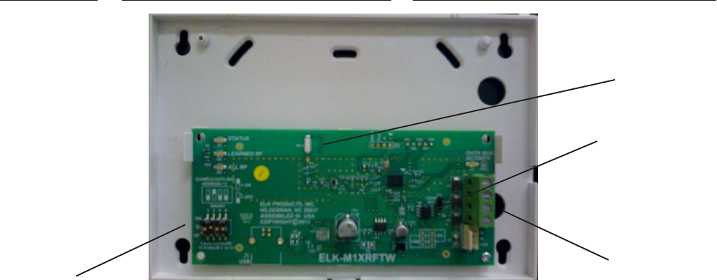
3. Antenna - The M1XRFTW uses a single on-board ceramic antenna. There is no external antenna re-
quired.
DIAGNOSTIC LED INDICATORS:
There a four (4) LEDs on the board that provide valuable information as to the operation of the M1XRF:
STATUS (Data Bus Status) - Multiple conditions exist for this LED:
OFF = No Power to the M1XRF
ON Solid = Power is good but it is not yet enrolled with the M1 or the Microprocessor is not functioning.
BLINKING = 2 different blink rates:
- Slow "one blink per second" indicates Normal Operating mode.
- Rapid "two quick blinks with a brief off time" indicated the Receiver is in Bootloader mode, indicating it has
not yet been flashed with application firmware. This should only occur if you are field updating the unit.
It will not be operational until application firmware has been flashed into the unit using ElkRP.
LEARNED RF - This LED will momentarily turn on when the M1XRF receives a valid transmitter and is in the process of
sending the signal packet back to the M1 Controller. As soon as the packet is acknowledged by the M1 Controller
the LED will turn Off.
ALL RF - This LED blinks whenever ANY Elk RF transmitter is heard or detected.
DATA BUS ACTIVE - This LED blinks near continuously and indicated activity on the M1 Data Bus.
INSTALL UNIT * SET ADDRESS AND OPTION JUMPERS * ACTIVATE M1 BUS ENROLLMENT PROCESS
RS-485
Data Bus
Connections
Data Bus
Address
Switches
NOTE: Jumper JP1makes it convenient to terminate the RS-485 Data Bus if this is the last installed device.
ELK-M1XRFTW Two-Way Receiver/Transceiver
ELK-M1XRFEG
JP1 Bus
Terminating
Jumper
ANT1
On-board
Antenna

M1XRFTW Installation Manual Page 5
Setting the M1XRF Data Bus Address and the Starting Wireless Zone ID
Every device on the M1 RS-485 4-wire data bus must have a valid address setting (from 1 to 15) within it's device type.
TYPE 1 is for Keypads, TYPE 2 is for Hardwire and Wireless Input expanders, TYPE 3 is for Output expanders, TYPE 4 is
for Serial expanders. The device types allow address numbers to be re-used in each different device type. There are 4
address switches, each with an OFF or ON position (binary value 0 or 1) and decimal equiv. value of (1, 2, 4, or 8). The
total decimal value of the "ON" switches determines the data bus address. Set the switches to the desired data bus
address by referring to Tables 1-1 and 1-2. A small screwdriver may be helpful. See important information before
proceeding to "Data Bus Enrollment".
VERY IMPORTANT! PLEASE READ!
Since Hardwire and Wireless expanders share the same device type and same bus address range,
unintentional data bus "Conflicts" are possible with M1XRF Wireless Receiver(s) and M1XIN Hardwired
Expander(s) installed on the same control. These conflicts can be avoided with proper understanding of
the issues and careful planning and execution during installation. The important point to remember is
that M1XRF Wireless Receivers and M1XIN Zone Expanders share the same data bus addresses. Below
are some issues and recommendations to avoid addressing conflicts:
M1XIN Expanders: A single ELK-M1XIN Hardwired Zone Expander (M1XIN) provides 16 hardwired zones. The data bus
address SETS THE ID OF THE STARTING ZONE of each 16 zone group. See Table 1-1. If additional M1XINs are installed,
each must have a different address (usually the next available) to set the starting zone of the next 16 zone group. I.E., Each data
bus address equates to a specific group of 16 zone IDs. Everything works fine as long as there are NO DUPLICATE addresses.
M1XRF Receivers: The differences between a ELK-M1XRF Wireless Receiver and a ELK-M1XIN Zone Expander are:
1) A single M1XRF Receiver can add up to 144 wireless zones to the control. These are assigned in groups of 16 at a time.
One stipulation is that to have 144 total wireless zones the first group of 16 must begin at zone 17 and the balance of the
wireless zones must be sequential through zone 160. If any hardwired zone expanders are enrolled in the range of
zones 17 through 160 you lose one entire group of 16 wireless zones for every hardwired (16 zone) expander installed.
2) For added range and coverage redundancy multiple "like branded" M1XRF Wireless Receivers can be installed on the
bus. Redundant receivers can be assigned to any unused data bus address as long as it doesn't conflict with another
Type 2 device.
NOTE: The data bus address of an M1XRF Receiver does not inherently set starting wireless zone number. Even so,
Elk strongly encourages Installers to set the data bus address of the first M1XRF Receiver to the starting zone ID as
depicted in Tables 1-1 and 1-2. While the actual data bus address of the M1XRF could be address 10 and the first
group of 16 wireless zones could be programmed as 17-32, the disadvantages of doing this are potential zone
numbering conflicts when M1XIN Hardwired Zones Expanders exist.
Other important considerations when installing an M1XRF:
a) Although wireless zones are allocated in Groups with a minimum number of 16 zones each, you are not required to
utilize all 16 of the zones in each group.
b) Care must be taken to ensure that wireless zones NEVER spill over into data bus addresses already assigned to a
M1XIN Hardwired Zone Expander, or vs. versa.
c) Regardless of where the wireless zones start we strongly suggest that all additional wireless zones be contiguous and
that no M1XIN Hardwired Zone Expanders be installed at data bus addresses associated with those wireless zone
numbers. Data Bus Addresses whose zone IDs are effectively "overlapped" by wireless zones are considered
"reserved" for wireless use and should not be used by a hardwired zone expander. See Appendix C.
d) The last wireless zone number can NEVER be assigned higher than zone 160. Put another way, zones 161 through 208
cannot be wireless zones.
e) The maximum number of wireless zones is 144, therefore the last wireless zone number cannot be greater than 160.
Example: You decide to create 64 contiguous wireless zones. And the starting wireless zone ID is set to "17" (associated
with data bus address 2). That would mean that zones 17 to 31, 32 to 48, 49 to 64, and 65 to 80 are going to be wireless
zones. Based on Tables 1-1 and 1-2 it can be seen that zones 17 to 31 are associated with data bus address 2. Zones 32 to
48, 49 to 64, and 65 to 80 are associated with data bus addresses 3, 4, and 5 respectively. As a result, addresses 3,4, and 5
ARE NOT AVAILABLE for use by M1XIN Expanders because the wireless zones are overlapping these addresses.
NOTE: Consider whether the system may ever required more wireless or hardwired zones. If the answer is yes it
would be good to plan the data bus address assignments in such a way that future growth is possible without having
to default the control or totally re-arrange the addresses at a future date.

Page 6 M1XRFTW Installation Manual
Switch Settings
S1 S2 S3 S4
Off On Off Off
On On Off Off
Off Off On Off
On Off On Off
Off On On Off
On On On Off
Off Off Off On
On Off Off On
Off On Off On
--- -
--- -
--- -
--- -
--- -
Data Bus
Address
2
3
4
5
6
7
8
9
10
11
12
13
14
15
Other Jumper
Settings:
JP1 - Used to
engage a 120
Ohm resistor for
terminating the
RS-485 Data Bus.
See Data bus
wiring instructions
before use.
Suggested Wireless
"Starting Point"
Zone 17
Zone 33
Zone 49
Zone 65
Zone 81
Zone 97
Zone 113
Zone 129
Zone 145
not valid
not valid
not valid
not valid
not valid
Switch Settings
S1 S2 S3 S4
Off On Off Off
On On Off Off
Off Off On Off
On Off On Off
Off On On Off
On On On Off
Off Off Off On
On Off Off On
Off On Off On
On On Off On
Off Off On On
On Off On On
--- -
--- -
Data Bus
Address
2
3
4
5
6
7
8
9
10
11
12
13
14
15
Starting and Ending
Zone Numbers
Zones 17 - 32
Zones 33 - 48
Zones 49 - 64
Zones 65 - 80
Zones 81 - 96
Zones 97 - 112
Zones 113 - 128
Zones 129 - 144
Zones 145 - 160
Zones 161 - 176
Zones 177 - 192
Zones 193 - 208
not valid
not valid
Table 1-1 Table 1-2
M1XRF Wireless ReceiversM1XIN Zone Expanders
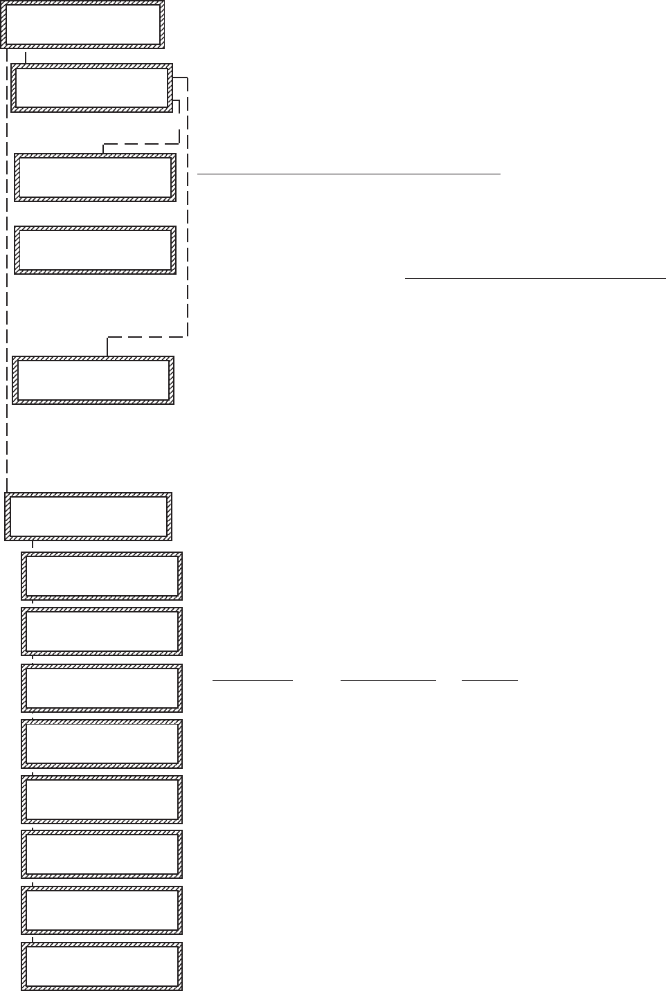
Data Bus Enrollment::
Once the address is set and the M1XRF is powered up it will be necessary to manually ENROLL the device so that the M1
Control knows it is present. This is accomplished either from keypad programming "Menu 1 - Bus Module Enrollment" or
from the ElkRP Remote Programming Software.
(The steps below require an M1 LCD Keypad)
1. Press the ELK key, then press 9 (or scroll up) to display 9 - Installation Programming. Press the
RIGHT arrow key to select this menu. The Installer Program Code (PIN) must be entered to access
this menu.
2. Enter the Installer Program Code. (The default code is 172839)
3. The first Installer Programming menu displayed will be "Bus Module Enrollment"
4. Press the RIGHT arrow key to select this menu. "Enrolling Bus Modules" will display
5. The control will transmit an enrollment message to all data bus devices, followed by a display
showing the total Bus Modules that are enrolled. To view the enrolled devices and/or remove a
device press the RIGHT arrow key next to the word Edit.
6. Press the * or Exit keys to exit Installer Programming.
XX Bus Modules
Enrolled, Edit rr
rr
r
Auth. Required
Enter Valid Pin
01-Bus Module
Enrollment
Data Bus Address Switches
M1XRFTW Installation Manual Page 7
Operation
What makes the Elk Two-Way technology different from existing "older" wireless technology?
Elk's Two-Way technology is vastly superior to traditional one-way wireless. Each transmission from an Elk sensor is
looking for an acknowledgement from the receiver. Positive acknowledgement of a transmission results in the sensor
generally only needing to send a single transmission. In a rare case where the transmission is not acknowledged by the
receiver, the sensor intelligently resends the transmission. Each sensor also monitors and adjusts its ideal RF power,
using only enough power to get a signal through, thereby maximizing the battery life of the sensor.
Confidence of signal strength at the time of installation another unique feature of the Elk Two-Way technology. As long
as the Installer mounts the sensor in it's final intended location prior to enrollingand activates the enrollment process
after mounting, a positive acknowledgement from the Receiver automatically indicates there is sufficient signal strength
for continued reliable operation.
Requirements for Programming the Receiver and Enrolling Transmitters:
The Receiver and wireless transmitters may be programmed using either the M1 Keypad Installer Programming or the ElkRP
Remote Programming software. The following pages document the options and steps for programming from the keypad.
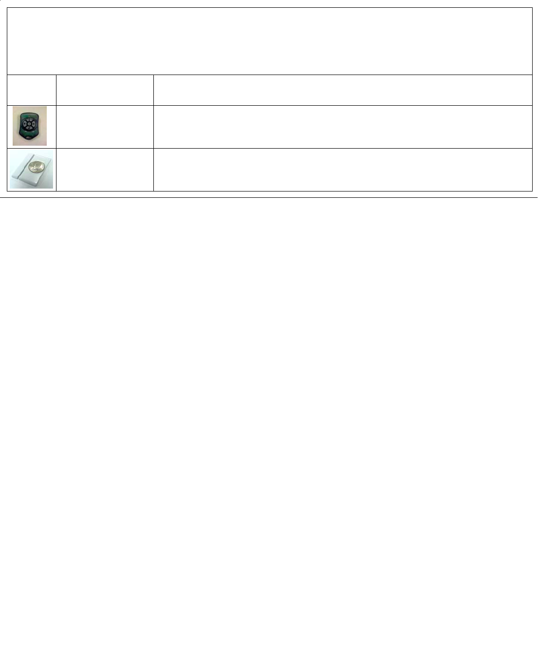
Page 8 M1XRFTW Installation Manual
ELK6050 Smoke Detector
Two-Way with Internal Sounder
Elk6021 Mini Two-Way
Door/Window Sensor
Use Enroll Method 1
Heat 'Rate Of Rise' Xmtr
Ademco Part # 5809
Glassbreak Xmtr
Ademco Part # 5853
Shock Sensor
Ademco Part # 5800SSI
Elk6010 5-Button Two-Way
Keychain Remote
Elk6022 Universal Two-Way
Door/Window Sensor, 2
Zones
1 Reed & 1 Ext. contact
ELK6030 Two-Way PIR
Motion Detector
Elk6020 Slim Two-Way Door/
Window Sensor
Single Channel
Shock Processor Xmtr,
3 Channels, 2 Ext. & 1 Reed
Sw.
Ademco Part # 5819
M1 Keypad Installer Level Programming: Use Menu 14 > sub-menu 3. Enter 3 digit Zone number or use
Up/Down arrows to scroll and locate a particular zone. Follow the specific Xmtr instructions outlined.
Part Number(s)Image
Use Enroll Method 2B NOTE: This Xmtr has 2 inputs and can be enrolled into 2 zones. The inputs have Loop # assignments
which must be set for each zone. The 1st zone could be assigned to Loop 1, the other to Loop 2. See sensor instructions. Repeat the
enroll process for the other zone prior to setting it's Loop #. Ext. inputs are N/C by default, but can be changed to N/O by setting zone
option WZnxxx 04 (Enable Option 2) to YES.
Use Enroll Method 2
Use Enroll Method 3
Special notes: In Menu 05 – Zone Definitions, program the zone def. as KEYFOB. In Menu 14 – Wireless Definitions, sub-menu 2,
program Supervision Type (option 2) as “0” for un-supervised. Keychain “FOB” do not send supervisory check-in signals. Also, under
sub-menu 4 each button may be assigned a specific functionality.
Use Enroll Method 2
Use Enroll Method 2
Use Enroll Method 2
Use Enroll Method 4
Use Enroll Method 4
Wireless Devices may be enrolled into M1 from the Keypad Installer Level Programming or from ElkRP
M1 Keypad Installer Level Programming utilizes Menu 14 and the “Lrn” mode process. Enrollment steps often vary between device types, so
please follow the specific enroll method mentioned beside each device.
ElkRP Remote Programming primarily involves typing in the TxID or serial number of the sensor, along with selecting the particular attributes.
Single Button Panic Xmtr
Ademco Part # 5802, 5802MN
Holdup Switch Xmtr
Ademco Part # 5869
Use Enroll Method 3 NOTE: Program Zone Def. as KEYFOB. The single button responds as KEY 4 and MUST be assigned a
functionality as Key # 4 under SubMenu 4. Consider setting the zone as non-supervised if customer is likely to carry sensor away from
the premises. This helps prevent nuisance missing transmitter troubles. Refer to WZnxxx 02 (Supervision Type).
Enroll Manually by typing in the Xmtr ID NOTE: Select Zone and press the left arrow "HW". Type in the Xmtr Decimal ID
shown on the unit. Set Loop to "1". Since this type of holdup sensor is generally fix mounted, the zone can and should be programmed
as supervised. Refer to WZnxxx 02 (Supervision Type).
Wireless Outdoor Motion Sensor
Xmtr
Ademco Part # 5800PIR-OD
Use Enroll Method 2
Panic Xmtr w/Dbl Key Press
Ademco Part # 5802MN2
Enroll Manually by typing in the Xmtr ID NOTE: Select Zone and press the left arrow "HW". Type in Xmtr Decimal ID
shown on the unit. Set Loop to "1". Program Zone Def. as desired. Consider setting the zone as non-supervised if customer is likely to
carry sensor away from the premises. This prevents nuisance missing transmitter troubles. Refer to WZnxxx 02 (Supervision Type).
Flood / Temperature Xmtr,
3 Channels
Ademco Part # 5821
Use Enroll Method 2B NOTE: This Xmtr has 3 inputs and can be enrolled into 3 zones. The inputs have Loop # assignements
which must be set for each zone. The 1st zone could be Loop 1, the 2nd Loop 2, and the 3rd Loop 3. See sensor instructions. Repeat
the enroll process each of the other zones prior to setting their Loop #. Ext. inputs are N/C by default, but can be changed to N/O by
setting zone option WZnxxx 04 (Enable Option 2) to YES.
Use Enroll Method 2B NOTE: This Xmtr can be configured as a stand-alone temperature sensor and/or as either a Remote
Temperature Sensor OR Flood Detector. Each channel must have its own zone and Loop # assignment of 1, 2, or 3. Refer to sensor
instructions. Repeat the enroll process for each of the other zones prior to setting their Loop #.
Elk Wireless Sensors and their enrollment procedures

M1XRFTW Installation Manual Page 9
Enroll Method 3 - Keychain “FOB” Remotes * BATTERY MUST ALREADY BE INSTALLED in this type sensor before proceeding *
Step 1 – Enter Keypad Installer Level Programming and navigate to Menu 14 – Wireless Definitions
Step 2 – Press the right arrow key and scroll or navigate to Option 3 – Learn Wireless Transmitter.
Step 3 – Press the right arrow key and scroll or navigate to the desired wireless zone number.
Step 4 – Press the right arrow key labeled “Lrn” to activate the enroll mode.
Step 5 – Press & Hold any one of the buttons on the Keychain Remote. Sensor is enrolled when keypad chimes & briefly displays the Xmtr 7 digit Hex ID.
Keypad will step to next available (blank) zone allowing rapid enrollment of sensors by tripping the next one to enroll.
Step 6 – To end Rapid Enrollment press ELK.
Step 7 – Press the ELK key twice when done.
Step 8 – Perform a Test of every sensor using the Keypad Walk Test (User Menu 3).
Enroll Method 2 – Single channel Sensors with a tamper switch. * REMOVE BATTERY from Sensor or verify it is NOT installed before proceeding *
Step 1 – After selecting the 3 digit zone number for this Sensor press the right arrow labeled “Lrn.” Note: This step may not be necessary if another Sensor has just been
enrolled and the Keypad automatically stepped forward (Rapid Enrollment).
Step 2 – Insert Battery into the Sensor. Sensor is enrolled when keypad chimes & briefly displays the 7 digit Sensor serial number (7 digit Hexidecimal number).
To permit Rapid Enrollment of multiple Sensors the Keypad will automatically step to next available zone.
Step 3 - To end rapid enrollment press ELK.
Step 4 - Press ELK twice when done.
Enroll Method 4 - Smoke & Heat Sensors * Verify Xmtr battery is installed before proceeding *
Step 1 - Twist off or separate main detector from backplate so tamper is activated.
Step 2 - Press the keypad right arrow labeled "Lrn". With a Smoke detector activate the test button procedure to trip sensor so that it transmits.
With a Heat detector press the activation button located on underside of circuit board. Sensor is enrolled when Keypad chimes & briefly displays 7 digit Hex ID.
Keypad will step to next available (blank) zone allowing rapid enrollment of sensors (except type that requires loop to be set first) by tripping the next one to enroll.
Step 3 - To end rapid enrollment press ELK.
Step 4 - To view the Xmtr Decimal ID & set the Loop # it is necessary to reselect the zone number and press the left arrow "HW".
Step 5 - Move cursor over to Loop using the right arrow. Set Loop # for smoke and heat Xmtr to a "1". When done press ELK twice.
Enroll Method 2B - Sensors with 2 or 3 channels and a tamper switch. * Verify Xmtr battery is installed before proceeding *
Step 1 - Remove sensor cover so that tamper is activated.
Step 2 - Press the keypad right arrow labeled "Lrn". Activate sensor so it transmits. Sensor is enrolled when keypad chimes & briefly displays Xmtr 7 digit Hex ID.
Keypad will step to next available (blank) zone allowing rapid enrollment of sensors (except type that requires loop to be set first) by tripping the next one to enroll.
Step 3 - To end rapid enrollment press ELK.
Step 4 - To view the Xmtr Decimal ID & set the Loop # it is necessary to reselect the zone number and press the left arrow "HW".
Step 5 - Move cursor to Loop with right arrow. Program Loop according to which Xmtr input this zone is using. Refer to Xmtr Mfg. supplied instructions. External input(s)
generally start at lower Loop (1 or 2), internal reed switches are generally the last Loop (2 or 3). When done press ELK twice.
NOTE: To use multiple channels select another zone for each & repeat the enrollment. Make sure to set the loop for each zone to an appropriate value.
Enroll Method 1 - Sensors with no tamper switch. * REMOVE BATTERY from sensor or verify it is not NOT installed before proceeding *
Step 1 – Enter Keypad Installer Level Programming and navigate to Menu 14 – Wireless Definitions
Step 2 – Press the right arrow key and scroll or navigate to Option 3 – Learn Wireless Transmitter.
Step 3 – Press the right arrow key and scroll or navigate to the desired wireless zone number.
Step 4 – Press the right arrow key labeled “Lrn” to activate the enroll mode.
Step 5 – Immediately insert the transmitter battery. If battery is already installed, remove it and wait 5 seconds, then re-install.
Note: A special enrollment command is sent to the receiver and the battery must be removed long enough for the circuit to recognize a power on startup.
Sensor is enrolled when keypad chimes & briefly displays the Xmtr 7 digit Hex ID. Keypad will step to next available (blank) zone allowing rapid enrollment of
sensors by tripping the next one to enroll.
Step 6 – To end Rapid Enrollment press ELK.
Step 7 – Press the ELK key twice when done.
Enrolling Wireless Devices into M1 from the Keypad Installer Level Programming
Enrolling Wireless Devices into M1 from ElkRP Software
Step 1 – Install the battery in the Sensor. It doesn’t matter at this point if the sensor is mounted or not-mounted.
Step 2 – On the ElkRP Account Details screen open the Wireless Setup.
Step 3 – Navigate to the Transmitters tab and double click the desired Zone number.
Step 4 – Place a check mark in the Enabled box.
Step 5 – Select the desired Supervision type as either: 0=Not Supervised (Keychain Fobs), 1=Normal Supervision (Most Burglary Sensors), 2=Fire Supervision
Step 6 – Consult the Instructions which come with each Sensor to determine if either Option 1 or Option 2 is supported. Follow recommendations of the sensor.
Step 7 – The box for PIR should NOT be checked UNLESS specifically mentioned in the Instructions accompanying the wireless PIR sensor.
Step 8 – The Keyfob User ID is for use with Keychain remotes to force their actions to be logged as a specific User ID. Ignore if the sensor is not a Keychain remote.
Step 9 – Type in the TxID number of the wireless sensor (printed on the sensor and packaging) and click Save. Do not use the DL or H ID blocks.
Step 10 – Program the Loop # according to the sensor input(s). By default most will be Loop “0”. If adding a sensor which has a secondary input like for an external
pushbutton or reed switch, follow the Instructions which came with that sensor for information on which Loop # to use..
Step 11 – Click Save and then Navigate to Zone (Inputs) > Wireless Group x. Program the Zone definition for each wireless sensor added.
Step 12 – Following programming, always perform a Test of every sensor using the Keypad Walk Test (User Menu 3.

Page 10 M1XRFTW Installation Manual
Wireless Submenu Description
This submenu is for Receiver options. To select this menu press the RIGHT arrow key, or
press the Up or Down arrow keys to scroll the submenus.
Rec. Option R03 is the time value for zones programmed as Supervisory Type 1 or "Non-Fire"
transmitters (see Xmit Transmitter Opt 02 below). The range is 001 to 255 hours. If a Type 1
sensor fails to check-in prior to the expiration of this time it is considered "missing". Factory
default setting is 024 hours. NOTE: A value less than 4 hours is NOT RECOMMENDED!
Rec. Option R04 is the time value for zones programmed as Supervisory Type 2 or "Fire"
transmitters (see Xmit Transmitter Opt 02 below). The range is 001 to 255 hours. If a Type 2
sensor fails to check-in prior to the expiration of this time it is considered "missing". Factory
default setting is 004 hours. NOTE: A value less than 4 hours is NOT RECOMMENDED!
This submenu is for specific transmitter options. Some options are not applicable to this
model of the M1XRF. To select this menu press the RIGHT arrow key, or press the Up or
Down arrow keys to scroll the submenus.
Use the UP and DOWN arrow keys to locate a particular wireless transmitter. Press the
RIGHT arrow key to select and program the displayed transmitter.
Displays whether a transmitter is enabled or disabled. This option CANNOT be used to add a
new device, but it can be used to temporarily suspend an already enrolled device. The enroll
process must be used to add a new transmitter, after which this location will be set to Yes.
Supervision type sets the expected check-in interval of a sensor. KeyChain Remotes (Fobs)
or devices which may leave the building program set this "0" = non supervised. Burglar
Sensors should have this option set as "1"=Normal Supervision. Fire Sensors should have
this option set as "3" = HI Supervision. See receiver selections R02 and R03 for supervision
time values. Valid values are: 0, 1, or 3 Factory default setting is 1 (Normal Supervision).
Pertains only to certain types of Transmitters. For KeyChain Remotes setting this option to
Yes converts buttons 1,2,3,4 to be instead buttons 5,6,7,8. Default is No. See list of
compatible Transmitters to determine which (if any) transmitters use this option.
Pertains to transmitters with Ext. contact terminals. Setting this to Yes permits Open Circuit
[N/O] switches. If set to No then only Closed Circuit [N/C] switches may be connected.
Default is No. See list of compatible Transmitters to determine which (if any)
transmitters use this option.
Used to program the User ID which will be logged when a Keychain Remote assigned to this
zone is used to arm of disarm. Valid range is 001 to 255. Numbers 001 to 199 mirror keypad
user codes. Note: Open/Close reports may be programmed for every User code.
Not used. If set to Yes the zone is auto-restored to normal in 8 seconds with no restoral
signal from the transmitter.
1:Rec Selb Prgr
Receiver Options
There are four (4) wireless setup submenus: 1-Receiver Options, 2-Xmitter Options, 3-Xmitter
Enroll, and 4-Keyfob Event Definitions. Use the UP or DOWN arrow keys to locate the desired
submenu, then press the right arrow key to select.
14-Wireless
Setup r
† Not evaluated by UL
2:Xmit Sel b Prgr
Transmitter Opt r
WZn017 04: = No r
Enable Option 2
WZn017 01: = No r
Enable Transmitr
WZn017 02: = 0 r
Supervision Type
WZn017 03: = No r
Enable Option 1
RO3:=024 Hours r
Reg. Supervision
WZn017:Sel bPrgr
Wireless Zone
WZn017 05: = 001 r
Keyfob User ID
WZn017 06: = No r
PIR Auto Restore
RO4:=004 Hours r
Fire Supervision
From the keypad enter the Installer Level Programming mode. Press ELK, 9 > (enter installer code).
Navigate to the Wireless Setup - Menu 14 and press the RIGHT arrow key to select.
Programming via Keypad
< continued on next page >
WZn017 shown as an example only!
M1XRFTW Installation Manual Page 11
Select the zone to enroll a new transmitter by entering the three (3) digit zone number OR by
scrolling to the zone number using the UP and DOWN arrow keys. NOTE: If a transmitter is
already enrolled for this zone the display will resemble 3c below. Otherwise, it will display
"TransmitrToLrn".
Press the RIGHT arrow key to select and program that zone.
This message will display and the M1 will speak: "Press Transmitter Button for Zone XXX",
UNLESS a transmitter is already enrolled (see below). Proceed to the transmitter and execute
the enroll process. I.E. Insert the batteyr or press the tamper button, etc. If successful the
keypad will chime and M1 will speak: "[Zone Name] Enrollment."
Displays the zone number and ID of the enrolled transmitter. NOTE: After a new transmitter is
enrolled this display advances to the next zone number and the M1 speaks "Press Transmit-
ter Button for Zone xxx." This permits rapid enrollment of additional transmitters in sequential
order. When enrollment is complete press the ELK key twice to exit the enrollment.
IMPORTANT! To delete or replace an existing transmitter navigate to transmitter option
"WZnxxx 01" and select "No". This will disable the existing transmitter.
Pressing the LEFT arrow marked "HW" at step 3a will produce display 3d. The left number
represents the transmitter ID in decimal notation. Press the RIGHT arrow key to move cursor
over to Loop. For most Elk transmitters the Loop should automatically be set to "0". However,
for a sensor that offers both an internal reed switch PLUS external inputs for an external
contact the Loop would need to be changed to "1" in order for the external contact to be
functional.
WZone = xxx Push
TransmiterButton
WZone = 017 HW l
TransmitrToLrn r
3:Learn Selb Prgr
WirelessTransmtr
This submenu is used for manually enrolling transmitters. To select this menu press the
RIGHT arrow key, or press the Up or Down arrow keys to scroll submenus.
This menu is used to program the operation or "action" for Keychain Remote (FOB) buttons.
Each button can be assigned one of six (6) separate operations as explained below. To
select this menu press the RIGHT arrow key.
Press the UP or DOWN arrow keys to select a key (button) 1 to 8. Some keys (buttons) may
not be usable depending on the model. The definition or operation is programmed using a
four (4) digit event code derived from the Zone Definitions table located in the M1 Installation
Manual. The range is 0000 to 0030 See M1 Installer Manual, Appendix A, Event Codes.
By factory default the M1 programming is assigned to the following keyfob buttons with
printed symbols.
Key # / (ICON) M1 Default Value Operation
Key 1 / Lock Event=0027 KeyMomAway (Arm the Control)
Key 2 / Unlock Event=0029 KeyMomDisarm (Disarm the Control)
Key 3 / Light Event=0000 "No default function"
Key 4 / Asterisk Event=0000 "No default function"
Center Key on Elk6010 KeyChain Remote is not programmable. It is permanently set to
functin as a Information "I" key which can query the Elk Receiver for Status
DOUBLE KEY PRESSES
Pressing the Lock and Unlock buttons together momentarily will trigger the event assigned
to Key 7. The M1 Default Event Value is "0000" or "No default function".
Pressing the Light and Asterisk buttons together momentarily will trigger the event assigned
to Key 8. The M1 Default Event Value is "0000" or "No default function".
WZone = 17 shown as example only!
WZone = xxx
Enrolled ABCDE1
Key=1 Evt=0000r
[name of event]
Key=2 Evt=0000r
[name of event]
Key=3 Evt=0000r
[name of event]
Key=4 Evt=0000r
[name of event]
Key=5 Evt=0000r
[name of event]
Key=6 Evt=0000r
[name of event]
Key=7 Evt=0000r
[name of event]
Key=8 Evt=0000r
[name of event]
4:KeyfobSelb Prgr
Event Definition
WZone = xxx HW l
A0000000 Loop=0
3b
3c
3d
3a
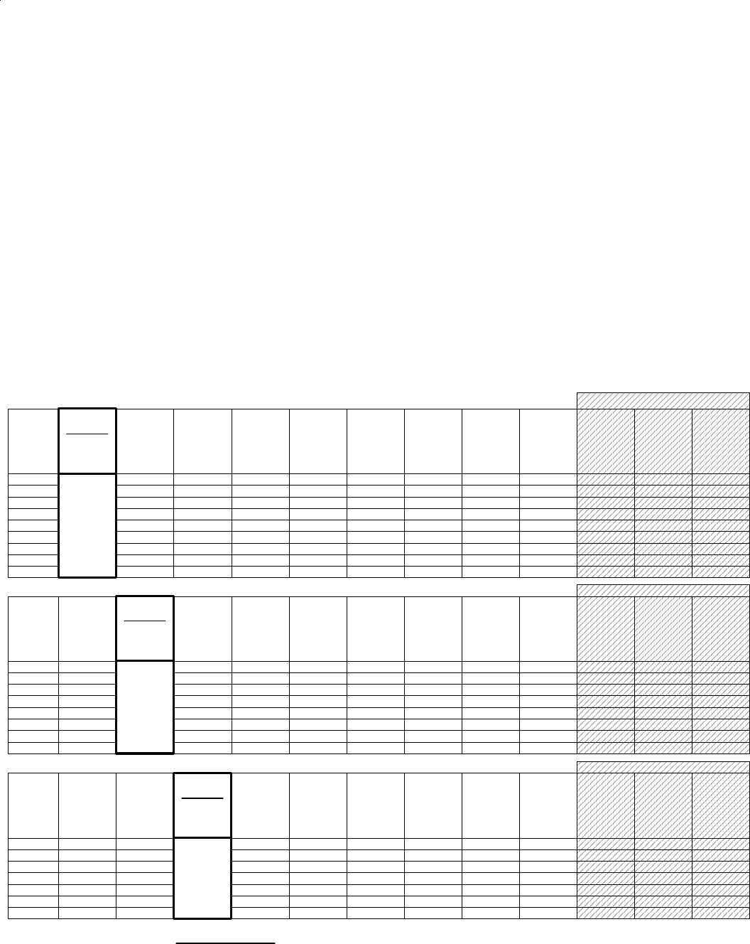
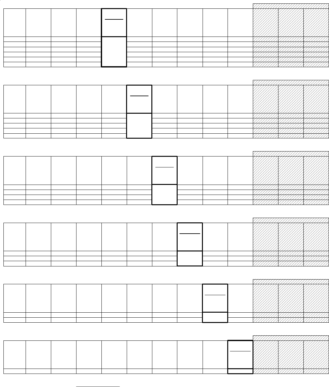
Page 12 M1XRFTW Installation Manual
H or RRF
Total
Wireless
Zones
(max.)
16 H or RRF H or RRF H or RRF H or RRF H or RRF H or RRF H or RRF H or RRF H or RRF H or RRF
Data Bus
Addr 12
Zn 177-192
* * H or RRF H or RRF H or RRF H or RRF H or RRF H or RRF H or RRF
H or RRF H or RRF H or RRF H or RRF H or RRF H or RRF H or RRF
H or RRF H or RRF H or RRF H or RRF H or RRF H or RRF H or RRF
* * * ** * H or RRF H or RRF H or RRF H or RRF H or RRF H or RRF
* ** * * * * ** * H or RRF H or RRF H or RRF H or RRF H or RRF
* * * ** * * * * ** * H or RRF H or RRF H or RRF H or RRF
* ** * * * * * * ** * H or RRF H or RRF H or RRF
* * * * * * * * * * * * H or RRF H or RRF* ** *
* *
H or RRF
H or RRF
H or RRF
H or RRF
H or RRF
H or RRF
H or RRF
H or RRF
Data Bus
Addr 13
Zn 193-208
Data Bus
Addr 9
Zn 129-144
Data Bus
Addr 11
Zn 161-176
Data Bus
Addr 8
Zn 113-128
Data Bus
Addr 6
Zn 81 - 96
Data Bus
Addr 3
Zn 33 - 48
Data Bus
Addr 4
Zn 49 - 64
Data Bus
Addr 7
Zn 97 - 112
Data Bus
Addr 5
Zn 65 - 80
Data Bus
Addr 10
Zn 145-160
32
48
64
80
96
112
128
144
* * * *
H or RRF
* * * * * *
H or RRF
H or RRF
* *M1XRF
Starting
Zn ID #17
Data bus
Addr 2
Zn 17-32
H or RRF
Total
Wireless
Zones
(max.)
16 H or RRF H or RRF H or RRF H or RRF H or RRF H or RRF H or RRF H or RRFH or RRF H or RRF
Data Bus
Addr 12
Zn 177-192
* * H or RRF H or RRF H or RRF H or RRFH or RRF H or RRF H or RRF
H or RRF H or RRF H or RRF H or RRF H or RRFH or RRF H or RRF
H or RRF H or RRF H or RRF H or RRF H or RRFH or RRF H or RRF
* * * ** * H or RRF H or RRF H or RRF H or RRFH or RRF H or RRF
* ** * * * * ** * H or RRF H or RRF H or RRFH or RRF H or RRF
* * * ** * * * * ** * H or RRF H or RRFH or RRF H or RRF
* ** * * * * * * ** * H or RRFH or RRF H or RRF* *
H or RRF
H or RRF
H or RRF
H or RRF
H or RRF
H or RRF
H or RRF
Data Bus
Addr 13
Zn 193-208
Data Bus
Addr 9
Zn 129-144
Data Bus
Addr 11
Zn 161-176
Data Bus
Addr 8
Zn 113-128
Data Bus
Addr 6
Zn 81 - 96
Data Bus
Addr 4
Zn 49 - 64
Data Bus
Addr 7
Zn 97 - 112
Data Bus
Addr 5
Zn 65 - 80
Data Bus
Addr 10
Zn 145-160
32
48
64
80
96
112
128
* * * *
H or RRF
* * * * * *
H or RRF
H or RRF
* *
M1XRF
Data Bus
Addr 2
Zn 17 -32
Starting
Zn ID #33
Data bus
Addr 3
Zn 33-48
H or RRF
Total
Wireless
Zones
(max.)
16 H or RRF H or RRF H or RRF H or RRF H or RRF H or RRF H or RRF H or RRFH or RRF H or RRF
Data Bus
Addr 12
Zn 177-192
* * H or RRF H or RRF H or RRF H or RRFH or RRF H or RRF H or RRF
H or RRF H or RRF H or RRF H or RRF H or RRFH or RRF H or RRF
H or RRF H or RRF H or RRF H or RRF H or RRFH or RRF H or RRF
* * * ** * H or RRF H or RRF H or RRF H or RRFH or RRF H or RRF
* ** * * * * ** * H or RRF H or RRF H or RRFH or RRF H or RRF
* * * ** * * * * ** * H or RRF H or RRFH or RRF H or RRF
H or RRF
H or RRF
H or RRF
H or RRF
H or RRF
H or RRF
Data Bus
Addr 13
Zn 193-208
Data Bus
Addr 9
Zn 129-144
Data Bus
Addr 11
Zn 161-176
Data Bus
Addr 8
Zn 113-128
Data Bus
Addr 6
Zn 81 - 96
Data Bus
Addr 7
Zn 97 - 112
Data Bus
Addr 5
Zn 65 - 80
Data Bus
Addr 10
Zn 145-160
32
48
64
80
96
112
* * * *
H or RRF
* * * * * *
H or RRF
H or RRF
* *
Data Bus
Addr 2
Zn 17 -32
Data Bus
Addr 3
Zn 33 - 48
Starting
Zn ID #49
Data Bus
Addr 4
Zn 49 - 64
M1XRF
Cells marked " * * " indicate a Reserved Address which can only be used for wireless zones.
Cells marked " RRF " indicate bus addresses where ONLY a redundant M1XRF Receiver can be installed.
Cells marked " H or RRF " indicate bus addresses where either a M1XIN Hardwired Expander OR a redundant M1XRF Receiver can be installed.
These tables are intended to help visualize how the Wireless Zones and Hardwired Zones share the data bus address assignments.
They should help with the setting of a starting zone ID and data bus address(s) to obtain the total and best mix of wireless and
hardwired zones. At a minimum, the left column shows the total "max." wireless zones that may be obtained based on the starting
zone ID and data bus addresses chosen.
1. Each table has a bolded column showing the 1st wireless zone ID at a particular value (associated with a data bus address).
NOTE: The total (max.) number of wireless zones is decreased by 16 zones for any hardwired expanders installed or
enrolled in the range of zones 17 through 160. This is because only zones 17 through 160 can be used for wireless.
2. Decide how many "total" wireless zones might be required for the job. This narrow down which table to concentrate on.
3. Consider existing or future M1XIN hardwired zone expanders. The wireless starting zone ID is critical if you want all wireless zones to be
sequential with no hardwired zones interspersed between them. The following are some suggested guidelines:
- If the job needs 16 hardwired zones or less with no plans for expansion then start the first wireless at zone 17 (associated with data bus
address 2). This leaves the most room for future wireless expansion all the way up to zone 160.
- If the job needs lots of hardwired zones and only a handful of wireless zones consider starting the M1XRF at a higher address, leaving room
for future hardwired expansion at the lower addresses.
4. Select any table below and start from the left column by choosing the total number of wireless zones required. Follow the row of cells across
to the bold column displaying the starting zone ID and associated data bus address where you wish to begin.
- Cells marked with "* *" indicate bus addresses "reserved" exclusively for wireless zones. However, any of these addresses may also be used
for a redundant M1XRF Receiver. Redundant Receivers provide additional range and coverage for extremely large or difficult buildings. See
Appendix C regarding Redundant Receivers.
- Cells marked "RRF" indicate bus addresses where ONLY a redundant M1XRF Receiver can be installed.
- Cells marked "H or RRF" indicate bus addresses where either a M1XIN Hardwired Expander OR a redundant M1XRF Receiver can be installed.
NOTE: An M1XRF installed for redundancy does not increase the number of wireless zones, it only increases
range and/or coverage.No RF Zones Here
No RF Zones Here
No RF Zones Here
Appendix A - Data Bus Selection Tables
M1XRFTW Installation Manual Page 13
H or RRF
Total
Wireless
Zones
(max.)
16 H or RRF H or RRF H or RRF H or RRF H or RRFH or RRFH or RRFH or RRFH or RRF H or RRF
Data Bus
Addr 12
Zn 177-192
* * H or RRF H or RRFH or RRFH or RRFH or RRF H or RRF H or RRF
H or RRF H or RRFH or RRFH or RRFH or RRFH or RRF H or RRF
H or RRF H or RRFH or RRFH or RRFH or RRFH or RRF H or RRF
H or RRF
H or RRF
H or RRF
Data Bus
Addr 13
Zn 193-208
Data Bus
Addr 9
Zn 129-144
Data Bus
Addr 11
Zn 161-176
Data Bus
Addr 8
Zn 113-128
Data Bus
Addr 10
Zn 145-160
32
48
64
* * * *
H or RRF
* * * * * *
H or RRF
H or RRF
M1XRF
Data Bus
Addr 2
Zn 17 -32
Data Bus
Addr 3
Zn 33 - 48
Data Bus
Addr 4
Zn 49 - 64
Data Bus
Addr 5
Zn 65 - 80
Data Bus
Addr 6
Zn 81 - 96
Starting
Zn ID #97
Data Bus
Addr 7
Zn 97 - 112
H or RRF
Total
Wireless
Zones
(max.)
16 H or RRF H or RRF H or RRF H or RRFH or RRFH or RRFH or RRFH or RRFH or RRF H or RRF
Data Bus
Addr 12
Zn 177-192
* * H or RRFH or RRFH or RRFH or RRFH or RRF H or RRF H or RRF
H or RRFH or RRFH or RRFH or RRFH or RRFH or RRF H or RRF
H or RRF
H or RRF
Data Bus
Addr 13
Zn 193-208
Data Bus
Addr 9
Zn 129-144
Data Bus
Addr 11
Zn 161-176
Data Bus
Addr 10
Zn 145-160
32
48 * * * *
H or RRF H or RRF
H or RRF
M1XRF
Data Bus
Addr 2
Zn 17 -32
Data Bus
Addr 3
Zn 33 - 48
Data Bus
Addr 4
Zn 49 - 64
Data Bus
Addr 5
Zn 65 - 80
Data Bus
Addr 6
Zn 81 - 96
Data Bus
Addr 7
Zn 97 - 112
Starting
Zn ID #113
Data Bus
Addr 8
Zn 113-128
H or RRF
Total
Wireless
Zones
(max.)
16 H or RRF H or RRF H or RRFH or RRFH or RRFH or RRFH or RRFH or RRFH or RRF H or RRF
Data Bus
Addr 12
Zn 177-192
* *H or RRFH or RRFH or RRFH or RRFH or RRF H or RRF H or RRF
H or RRF
Data Bus
Addr 13
Zn 193-208
Data Bus
Addr 11
Zn 161-176
Data Bus
Addr 10
Zn 145-160
32 H or RRF H or RRF
M1XRF
Data Bus
Addr 2
Zn 17 -32
Data Bus
Addr 3
Zn 33 - 48
Data Bus
Addr 4
Zn 49 - 64
Data Bus
Addr 5
Zn 65 - 80
Data Bus
Addr 6
Zn 81 - 96
Data Bus
Addr 7
Zn 97 - 112
Data Bus
Addr 8
Zn 113-128
Starting
Zn ID #129
Data Bus
Addr 9
Zn 129-144
Total
Wireless
Zones
(max.)
16 H or RRF H or RRFH or RRFH or RRFH or RRFH or RRFH or RRFH or RRFH or RRF H or RRF
Data Bus
Addr 12
Zn 177-192
H or RRF
Data Bus
Addr 13
Zn 193-208
Data Bus
Addr 11
Zn 161-176
M1XRF
Data Bus
Addr 2
Zn 17 -32
Data Bus
Addr 3
Zn 33 - 48
Data Bus
Addr 4
Zn 49 - 64
Data Bus
Addr 5
Zn 65 - 80
Data Bus
Addr 6
Zn 81 - 96
Data Bus
Addr 7
Zn 97 - 112
Data Bus
Addr 8
Zn 113-128
Data Bus
Addr 9
Zn 129-144
Starting
Zn ID #145
Data Bus
Addr 10
Zn 145-160
H or RRF
Total
Wireless
Zones
(max.)
16 H or RRF H or RRF H or RRF H or RRF H or RRF H or RRFH or RRFH or RRFH or RRF H or RRF
Data Bus
Addr 12
Zn 177-192
* * H or RRF H or RRF H or RRFH or RRFH or RRF H or RRF H or RRF
H or RRF H or RRF H or RRFH or RRFH or RRFH or RRF H or RRF
H or RRF H or RRF H or RRFH or RRFH or RRFH or RRF H or RRF
* * * ** * H or RRF H or RRFH or RRFH or RRFH or RRF H or RRF
H or RRF
H or RRF
H or RRF
H or RRF
Data Bus
Addr 13
Zn 193-208
Data Bus
Addr 9
Zn 129-144
Data Bus
Addr 11
Zn 161-176
Data Bus
Addr 8
Zn 113-128
Data Bus
Addr 7
Zn 97 - 112
Data Bus
Addr 10
Zn 145-160
32
48
64
80
* * * *
H or RRF
* * * * * *
H or RRF
H or RRF
* *
M1XRF
Data Bus
Addr 2
Zn 17 -32
Data Bus
Addr 3
Zn 33 - 48
Data Bus
Addr 4
Zn 49 - 64
Data Bus
Addr 5
Zn 65 - 80
Starting
Zn ID #81
Data Bus
Addr 6
Zn 81 - 96
Cells marked " * * " indicate a Reserved Address which can only be used for wireless zones.
Cells marked " RRF " indicate bus addresses where ONLY a redundant M1XRF Receiver can be installed.
Cells marked " H or RRF " indicate bus addresses where either a M1XIN Hardwired Expander OR a redundant M1XRF Receiver can be installed.
H or RRF
Total
Wireless
Zones
(max.)
16 H or RRF H or RRF H or RRF H or RRF H or RRF H or RRF H or RRFH or RRFH or RRF H or RRF
Data Bus
Addr 12
Zn 177-192
* * H or RRF H or RRF H or RRFH or RRFH or RRF H or RRF H or RRF
H or RRF H or RRF H or RRF H or RRFH or RRFH or RRF H or RRF
H or RRF H or RRF H or RRF H or RRFH or RRFH or RRF H or RRF
* * * ** * H or RRF H or RRF H or RRFH or RRFH or RRF H or RRF
* ** * * * * ** * H or RRF H or RRFH or RRFH or RRF H or RRF
H or RRF
H or RRF
H or RRF
H or RRF
H or RRF
Data Bus
Addr 13
Zn 193-208
Data Bus
Addr 9
Zn 129-144
Data Bus
Addr 11
Zn 161-176
Data Bus
Addr 8
Zn 113-128
Data Bus
Addr 6
Zn 81 - 96
Data Bus
Addr 7
Zn 97 - 112
Data Bus
Addr 10
Zn 145-160
32
48
64
80
96
* * * *
H or RRF
* * * * * *
H or RRF
H or RRF
* *
M1XRF
Data Bus
Addr 2
Zn 17 -32
Data Bus
Addr 3
Zn 33 - 48
Data Bus
Addr 4
Zn 49 - 64
Starting
Zn ID #65
Data Bus
Addr 5
Zn 65 - 80
No RF Zones Here
No RF Zones Here
No RF Zones Here
No RF Zones Here
No RF Zones Here
No RF Zones Here
Appendix A - Data Bus Selection Tables (cont'd)
Page 14 M1XRFTW Installation Manual
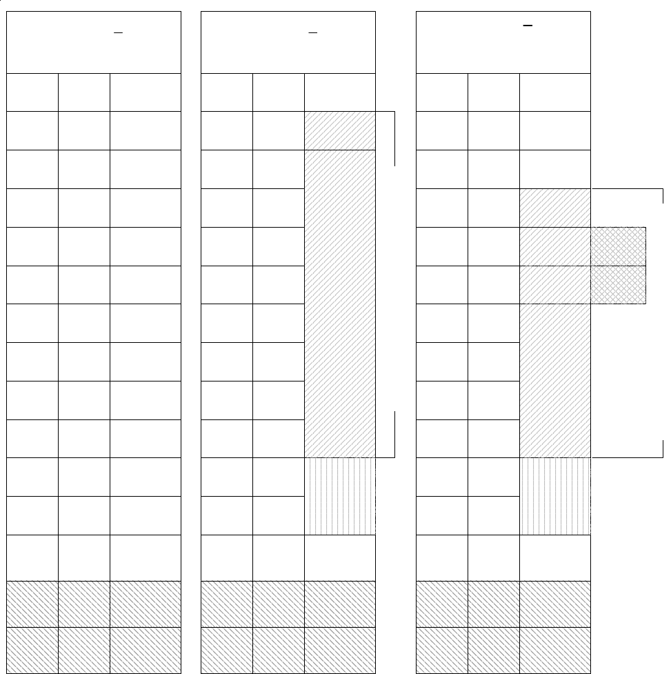
Example A
All 208 Zones as Hardwired
Zones
1-16
Inputs on
Main Panel
Zones
17-32 M1XIN
Zones
33-48
Zones
49-64
Zones
65-80
Zones
81-96
Zones
97-112
Zones
113-128
Zones
129-144
Zones
145-160
Zones
161-176
Zones
177-192
Zones
193-208
Example B
16 Hardwired Zones
144 Wireless Zones
NO
M1XIN
Expanders
on these
addresses
Example C
48 Hardwired Zones
112 Wireless Zones
PLUS 2 Redundant Receivers
Bus
Addr x
Bus
Addr 2
M1XIN
Bus
Addr 3
M1XIN
Bus
Addr 4
M1XIN
Bus
Addr 5
M1XIN
Bus
Addr 6
M1XIN
Bus
Addr 7
M1XIN
Bus
Addr 8
M1XIN
Bus
Addr 9
M1XIN
Bus
Addr 10
M1XIN
Bus
Addr 11
M1XIN
Bus
Addr 12
M1XIN or
Keypad
Zones
Bus
Addr 13
Zones
1-16
Inputs on
Main Panel
Zones
17-32
Zones
33-48
Zones
49-64
Zones
65-80
Zones
81-96
Zones
97-112
Zones
113-128
Zones
129-144
Zones
145-160
Zones
161-176
Zones
177-192
Zones
193-208
Bus
Addr x
Bus
Addr 2
Bus
Addr 3
Bus
Addr 4
Bus
Addr 5
Bus
Addr 6
Bus
Addr 7
Bus
Addr 8
Bus
Addr 9
Bus
Addr 10
M1XIN or
Keypad
Zones
Bus
Addr 13
M1XRF
M1XIN or
Redundant
M1XRF *
NO
M1XIN
Expanders
on these
addresses
Zones
1-16
Inputs on
Main Panel
Zones
17-32
Zones
33-48
Zones
49-64
Zones
65-80
Zones
81-96
Zones
97-112
Zones
113-128
Zones
129-144
Zones
145-160
Zones
161-176
Zones
177-192
Zones
193-208
Bus
Addr x
Bus
Addr 2
Bus
Addr 3
Bus
Addr 4
Bus
Addr 5
Bus
Addr 6
Bus
Addr 7
Bus
Addr 8
Bus
Addr 9
Bus
Addr 10
M1XIN or
Keypad
Zones
Bus
Addr 13
M1XRF
M1XIN
M1XIN
Bus
Addr 14
Bus
Addr 15
N/A
N/A
N/A
N/A
Maximum of 112 Wireless Zones
< ------- Redundant M1XRF *
< ------- Redundant M1XRF *
Maximum of 144 Wireless Zones
M1XIN or
Redundant
M1XRF *
Bus
Addr 11
Bus
Addr 12
Bus
Addr 11
Bus
Addr 12
Bus
Addr 14
Bus
Addr 15
N/A
N/A
N/A
N/A
Bus
Addr 14
Bus
Addr 15
N/A
N/A
N/A
N/A
Appendix B - Examples of Zone Configurations
M1XRFTW Installation Manual Page 15
Appendix D - Updating Firmware in the ELK-M1XRF
Operating firmware is stored in “Flash” memory. This state-of-the-art memory allows electronic field updates and eliminates
the old fashion method of changing IC chips or shipping boards back to the factory. As new firmware updates become avail-
able, they will be posted on ELK’s Dealer ONLY restricted website found at www.elkproducts.com. NOTE: Firmware updating
can only be done through the M1 Control using a Direct to PC Com port connection or an optional Ethernet Network connec-
tion. Dial-up connections cannot be used to perform firmware updates.
How to Update Firmware:
1. Physically connect the Computer and Control using either the RS-232 Serial Ports or the M1XEP Ethernet Interface.
3. Start ElkRP and open the account belonging to the control. Click on the Connection menu icon and establish a connection.
Again, use the appropriate Direct using Com_ OR Network options.
4. Click on Update/Verify Firmware from the Send/Rcv menu icon.
5. On the Update/Verify screen, select the device to be updated. In this case it is a Input Expander. Then also select the
“Update to new firmware” option. Then click Continue.
6. The Update Firmware screen displays the device name, the current Firmware, Hardware, and Bootware version, and a pull
down window for selecting the firmware version to use on the update. Select the appropriate firmware that you wish to use.
NOTE: All update (.bin) files that are downloaded or received should be stored in your ~Program Files\ElkRP\Updates
directory. This is where RP looks for all update files.
7. Click on the check box for “Update”. If “Reprogram” or “Rollback” is displayed the firmware file is the same as OR older that
what is in the control. Reprogramming with the same firmware is a waste of time but was included for factory testing
purposes. Rollback is not recommended except under the guidance of Elk Technical Support.
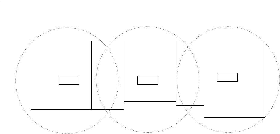
After the first M1XRF Receiver has been installed, additional receivers can be installed for redundancy or improved coverage
and range. Each addtional M1XRF will require its own data bus address and must be enrolled into the control. The data bus
address setting of any additional "redundant" M1XRF Receivers can be any unused data bus address except for addresses 13,
14, 15, 16.
NOTE: While M1XIN Expanders cannot be assigned to addresses overlapped by wireless zones this is not true for M1XRF
Receivers. From the example above, addresses 3, 4, and 5 could be used by additional "redundant" M1XRF Receivers. In
theory it is possible to install up to 11 total M1XRF Receivers onto a single M1 or M1EZ8 control, but only if there were NO
M1XIN Expanders installed.
* For large installations or added coverage in areas with poor wireless conditions, additional M1XRF "Redundant" Receivers can be connected to
the data bus. Redundant receivers must be addressed and enrolled for proper supervision. Loss of any enrolled bus device causes a Missing Bus
Device Trouble. NOTE: Redundant M1XRFs can be set to any of the unused addresses that fall in the total wireless zone number assignments.
Offices
Shipping M1XRF
M1XRF M1XRF
Warehouse Production Sales
EXAMPLE OF LARGE COMMERCIAL BUILDING with 3 M1XRF Receivers
Appendix C - Installing Multiple Redundant Receivers
Page 16 M1XRFTW Installation Manual