ELPRO Technologies E2900AA1 900 MHz FREQUENCY HOPPING SPREAD SPECTRUM TRANSCEIVER User Manual man E2 1 0 10 3 Scott
ELPRO Technologies Pty Ltd 900 MHz FREQUENCY HOPPING SPREAD SPECTRUM TRANSCEIVER man E2 1 0 10 3 Scott
Users Manual
ELPRO Technologies, 9/12 Billabong Street, Stafford Qld, 4053 Australia.
Tel: +61 7 3352 8600 Fax: +61 7 3352 8677 Email: sales@elprotech.com
Web: www.elprotech.com
ELPRO Support Help-line America (866) 713 4409 Rest of the world +617 3352 8624
V1.0
E2
User Manual

E2 Wireless I/O Page 1
Page 2 E2 Wireless I/O
Thank you for your selection of the E2 Modem. We trust it will give you many years of
valuable service.
ATTENTION!
Incorrect termination of supply wires may cause internal damage and will void warranty. To
ensure your E2 module enjoys a long life, double check ALL your connections with the user
manual before turning the power on.
CAUTION:
To comply with FCC RF Exposure requirements in section 1.1310 of the FCC Rules,
antennas used with this device must be installed to provide a separation distance of at
least 20 cm from all persons to satisfy RF exposure compliance.
All equipment must be properly grounded for safe operations. All equipment should be
serviced only by a qualified technician
Do Not:
operate the transmitter when someone is within 20 cm of the antenna
operate the transmitter unless all RF connectors are secure and any open connectors are
properly terminated
operate the equipment near electrical blasting caps or in an explosive atmosphere
SAFETY Notice:
Exposure to RF energy is an important safety consideration. The FCC has adopted a
safety standard for human exposure to radio frequency electromagnetic energy emitted by
FCC regulated equipment as a result of its actions in Docket 93-62 and OET Bulletin 65
Edition 97-01.

E2 Wireless I/O Page 3
FCC Notice:
This device complies with Part 15.247 of the FCC Rules.
Operation is subject to the following two conditions:
This device may not cause harmful interference and
This device must accept any interference received, including interference that may cause
undesired operation.
This device must be operated as supplied by ELPRO. Any changes or modifications made
to the device without the written consent of ELPRO may void the user’s authority to operate
the device.
This device must be installed by professional installers in compliance with 47 CFR Part 15
Subpart C Section 15.204 and 15.205, who will be responsible for maintaining EIRP no
greater than 36 dBm in accordance with 47 CFR Part 15 Subpart C Section 15.247
(b)(2)(4).
In accordance with 47 CFR Part 15 Subpart C Section 15.204 only the following
antenna/coax cable kits can be used.
Manufacturer Model Number Coax Kit Net
Elpro SG-900-6 CC10/900 5dBi Gain
Elpro SG-900-6 CC20/900 2dBi Gain
Elpro YU6/900 CC20/900 4dBi Gain
• Part 15 –This device has been tested and found to comply with the limits for a Class
A digital device, pursuant to Part15 of the FCC rules (Code of Federal Regulations
47CFR Part 15). Operation is subject to the condition that this device does not
cause harmful interference.
• Notice Any changes or modifications not expressly approved by ELPRO could void
the user’s authority to operate this equipment.
This Device should only be connected to PCs that are covered by either FCC DoC or are
FCC certified.

Page 4 E2 Wireless I/O
IMPORTANT Notice:
ELPRO products are designed to be used in industrial environments, by experienced
industrial engineering personnel with adequate knowledge of safety design
considerations.
ELPRO radio products are used on unprotected license-free radio bands with radio noise
and interference. The products are designed to operate in the presence of noise and
interference, however in an extreme case, radio noise and interference could cause
product operation delays or operation failure. Like all industrial electronic products,
ELPRO products can fail in a variety of modes due to misuse, age, or malfunction. We
recommend that users and designers design systems using design techniques intended to
prevent personal injury or damage during product operation, and provide failure tolerant
systems to prevent personal injury or damage in the event of product failure. Designers
must warn users of the equipment or systems if adequate protection against failure has
not been included in the system design. Designers must include this Important Notice in
operating procedures and system manuals.
These products should not be used in non-industrial applications, or life-support systems,
without consulting ELPRO first.
• A radio license is not required in some countries, provided the module is installed
using the aerial and equipment configuration described in the E2 Installation Guide.
Check with your local distributor for further information on regulations.
• Operation is authorized by the radio frequency regulatory authority in your country
on a non-protection basis. Although all care is taken in the design of these units,
there is no responsibility taken for sources of external interference. Systems should
be designed to be tolerant of these operational delays.
• To avoid the risk of electrocution, the aerial, aerial cable, serial cables and all
terminals of the E2 module should be electrically protected. To provide maximum
surge and lightning protection, the module should be connected to a suitable earth
and the aerial, aerial cable, serial cables and the module should be installed as
recommended in the Installation Guide
• To avoid accidents during maintenance or adjustment of remotely controlled
equipment, all equipment should be first disconnected from the E2 module during
these adjustments. Equipment should carry clear markings to indicate remote or
automatic operation. E.g. "This equipment is remotely controlled and may start
without warning. Isolate at the switchboard before attempting adjustments."
• The E2 module is not suitable for use in explosive environments without additional
protection.
• The E2 Operates unlicensed Radio frequencies and proprietary protocols to
communicate over the radio. Nevertheless, If your system is not adequately
secured, third parties may be able to gain access to your data or gain control of
your equipment via the radio link. Before deploying a system make sure you have
considered the security aspects of your installation carefully.

E2 Wireless I/O Page 5
Limited Lifetime Warranty, Disclaimer and Limitation of
Remedies
ELPRO products are warranted to be free from manufacturing defects for the “serviceable
lifetime” of the product. The “serviceable lifetime” is limited to the availability of electronic
components. If the serviceable life is reached in less than three years following the original
purchase from ELPRO, ELPRO will replace the product with an equivalent product if an
equivalent product is available.
This warranty does not extend to:
• Failures caused by the operation of the equipment outside the particular product's
specification, or
• Use of the module not in accordance with this User Manual, or
• Abuse, misuse, neglect or damage by external causes, or
• Repairs, alterations, or modifications undertaken other than by an authorized Service
Agent.
ELPRO liability under this warranty is limited to the replacement or repair of the product.
This warranty is in lieu of and exclusive of all other warranties. This warranty does not
indemnify the purchaser of products for any consequential claim for damages or loss of
operations or profits and ELPRO is not liable for any consequential damages or loss of
operations or profits resulting from the use of these products. ELPRO is not liable for
damages, losses, costs, injury or harm incurred as a consequence of any representations,
warranties or conditions made by ELPRO or its representatives or by any other party,
except as expressed solely in this document.

Page 6 E2 Wireless I/O
TABLE OF CONTENTS
1 CHAPTER 1 – INTRODUCTION.........................................................................................8
1.1 Overview.........................................................................................................................................................8
1.2 Module Structure .........................................................................................................................................10
1.3 Getting Started.............................................................................................................................................11
2 CHAPTER 2 – INSTALLATION........................................................................................12
2.1 General..........................................................................................................................................................12
2.2 Power/Supply ...............................................................................................................................................12
2.3 Radio.............................................................................................................................................................13
900 MHz Spread Spectrum radio ....................................................................................................................13
Meshing capability...........................................................................................................................................14
2.4 Antenna.........................................................................................................................................................15
Dipole and Collinear antennas. .......................................................................................................................17
Yagi antennas..................................................................................................................................................17
2.5 Connections.................................................................................................................................................18
Ethernet port....................................................................................................................................................18
USB Device Port for configuration...................................................................................................................18
RS-232 port .....................................................................................................................................................18
RS-485 port with Modbus Support. .................................................................................................................19
“Factory Boot” switch.......................................................................................................................................20
USB Host port..................................................................................................................................................20
Dipswitch “Bank”..............................................................................................................................................20
Front panel connections..................................................................................................................................21
Digital Inputs....................................................................................................................................................21
Pulsed Inputs..................................................................................................................................................22
Digital Outputs (Pulsed Outputs).....................................................................................................................22
Digital Outputs (Pulsed Outputs).....................................................................................................................23
Analog Inputs...................................................................................................................................................24
Floating Differential Analog Inputs (AIN 1 & 2 only) ........................................................................................24
Single Ended Current Inputs (AIN 3 & 4 only).................................................................................................25
Single Ended Voltage Inputs ...........................................................................................................................25
Analog Outputs................................................................................................................................................26
3 CHAPTER 3 – OPERATION.............................................................................................27
3.1 Overview.......................................................................................................................................................27
3.2 Indications....................................................................................................................................................27
Front Panel Indications....................................................................................................................................27
I/O Indications..................................................................................................................................................28
Ethernet Indications.........................................................................................................................................28
3.3 System Design Tips.....................................................................................................................................29
System Dynamics............................................................................................................................................29
3.4 WIBMesh.......................................................................................................................................................30

E2 Wireless I/O Page 7
4 CHAPTER 4 – CONFIGURATION ....................................................................................31
4.1 First time.......................................................................................................................................................31
Default Configuration.......................................................................................................................................31
Accessing Configuration for the first time........................................................................................................31
4.2 Network Configuration................................................................................................................................34
4.3 Radio Settings..............................................................................................................................................35
4.4 WIBMesh Configuration......................................................................................................................37
4.5 WIBMesh Mappings.....................................................................................................................................38
Write Mappings ...............................................................................................................................................38
Read Mappings ...............................................................................................................................................39
Gather/Scatter Write Mappings.......................................................................................................................40
4.6 Serial Configuration ....................................................................................................................................42
Modbus TCP to RTU Gateway........................................................................................................................42
4.7 I/O Configuration .........................................................................................................................................44
Analog Inputs...................................................................................................................................................44
Analog Outputs................................................................................................................................................45
Digital Input......................................................................................................................................................46
Digital Output...................................................................................................................................................46
Pulsed Inputs...................................................................................................................................................46
4.8 Module Information .....................................................................................................................................47
4.9 System Tools ...............................................................................................................................................48
Reading Configuration File..............................................................................................................................48
Writing Configuration File................................................................................................................................48
Firmware Upgrade...........................................................................................................................................48
4.10 Address Map ..............................................................................................................................................48
Standard E2 I/O (Basic Local I/O with no expansion modules).......................................................................49
CHAPTER 5 – DIAGNOSTICS ............................................................................................51
5.1 IO Diagnostics.......................................................................................................................................51
5.2 Diagnostic Information.........................................................................................................................52
Connectivity .....................................................................................................................................................52
Statistics ..........................................................................................................................................................52
5 APPENDIX A.....................................................................................................................54
6 Appendix A I/O Store ...............................................................................................................................54
“Output Coils” ..................................................................................................................................................54
“Input Bits” .......................................................................................................................................................54
“Input Registers”..............................................................................................................................................55
“Holding Registers”..........................................................................................................................................56

Page 8 E2 Wireless I/O
1Chapter 1 – Introduction
1.1 Overview
The E2 range of I/O modules has been designed to provide standard “off-the-shelf”
telemetry functions, for an economic price. Telemetry is the transmission of data or
signals over a long distance via radio or twisted-pair wire cable.
Although the E2 Series is intended to be simple in its application, it provides many
sophisticated features, which will be explained in the following chapters.
This manual should be read carefully to ensure that the modules are configured and
installed to give reliable performance.
The E2 telemetry module replaces the earlier 105 and 905 E-series modules. It
provides on-board I/O via a front mounting 20-way connector and has provision for
extra expansion modules (ELPRO 115S or MODBUS devices) to be connected using a
standard RS485 serial connection.
The module can monitor the following types of signals
• Digital on/off signals - Contact Closure or Switch
• Analog continuously variable signals – Tank level, Motor speed, temperature, etc
• Pulsed signal - Frequency signal – Metering, accumulated total, rainfall, etc
• Internal Signals – Supply voltage, Supply failure, battery status, etc.
The modules monitor the input signals and transmit the values by radio or Ethernet
cabling to another module or modules that have been configured to receive this
information.
The E2 radio has been designed to meet the requirements of unlicensed operation for
remote monitoring and control of equipment. A radio licence is not required for the E2 in
many countries.
The E2 product will seamlessly operate with existing 905U wireless I/O modules the E3
products, which use the same basic hardware but extend the functionality with
additional interfaces including an LCD and multiple radio functionality.
The E2 operates on unlicensed radio channels in the 902-915MHz bands.
Input signals that are connected to the module are transmitted and appear as output
signals on other modules. A transmission occurs whenever a "change-of-state" occurs
on an input signal. A "change-of-state" of a digital or an internal digital input is a change
from "off" to "on" or vice-versa. A "change-of-state" for an analog input, internal analog
input or pulse input rate is a change in value of the signal of 3% (configurable from 0.8
to 75 %).
In addition to change-of-state messages, update messages are automatically
transmitted on a configurable time basis. This update ensures the integrity of the
system.

E2 Wireless I/O Page 9
Pulse inputs counts are accumulated and the total count is transmitted regularly
according to the configured update time.
The E2 modules transmit the input/output data using radio or Ethernet. The data frame
includes the "address" of the transmitting module and the receiving module, so that
each transmitted message is acted on only by the correct receiving unit. Each message
includes error checking to ensure that no corruption of the data frame has occurred due
to noise or interference. The module with the correct receiving "address" will
acknowledge the message with a return transmission (acknowledgement). If the original
module does not receive a correct acknowledgement, it will retry up to five times before
setting the communications fail status of that path. In critical paths, this status can be
reflected on an output on the module for alert purposes. The module will continue to try
to establish communications and retry, each time an update or change-of-state occurs.
A system can be a complex network or a simple pair of modules. An easy-to-use
configuration procedure allows the user to specify any output destination for each input.
Two versions of the E2 are available. The Legacy version provides for operation with
existing ELPRO wireless I/O devices (905 series and 105 series modules) The second
version provides enhanced features, including IP addressing, allowing thousands of
modules to exist in a system, and allowing Automatic routing of messages through
repeater stations.
Each E2 radio in a system may have up to 24 expansion I/O modules (ELPRO 115S)
connected by RS485 twisted pair. Any input signal at any module may be configured to
appear at any output on any module in the entire system.
Modules can be used as repeaters to re-transmit messages on to the destination
module. Repeaters can repeat messages on the radio channel or from the radio
channel to the serial channel (and serial to radio). Using Legacy protocol, up to five
repeater addresses may be configured for each input-to-output link. The meshing
protocol will automatically select other stations to act as repeaters as required.
The units may be configured by using a web browser connected to the Ethernet port or
using supplied system configuration software connected to the Module’s USB port. The
default configuration and software configuration is defined in Section 4 Configuration.
Page 10 E2 Wireless I/O
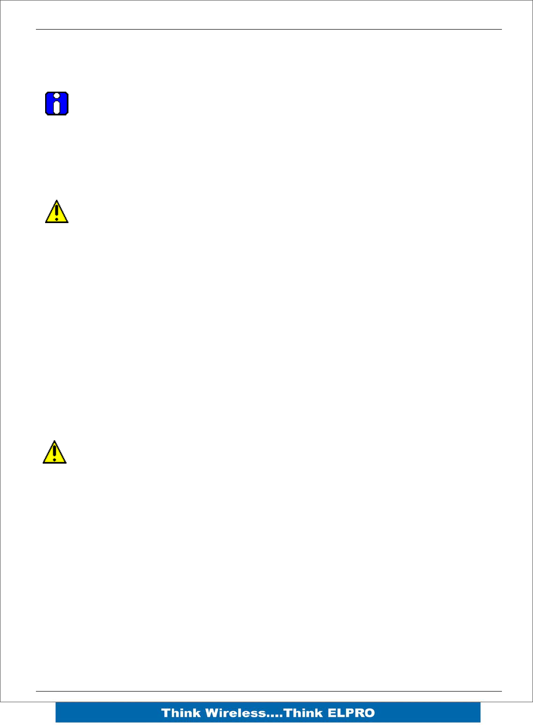
1.2 Module Structure
The E2 is made up of a number of basic sections, which all interface with a central
Input and output storage area (I/O Store).
The I/O Data Store provides storage for I/O data as well as providing services to other
processes in the system. The I/O Store provides eight different blocks of data - two
containing input and output bit data, two containing input and output word data, two
containing long-word type data and two containing floating-point data. The two files of
each type in turn support inputs and outputs on the local machine, and data storage for
the gateway function of the machine. These files are mapped into the address map as
described below. There are other register values within the database that can be used
for system management - these will be discussed later in this manual.
The Radio Interface allows the E2 to communicate with other modules within the
system using a proprietary radio protocol called “WIB-Net”. Messages from other E2
modules are received by the radio port and used to update the input values in the I/O
Data Store. The WIB-Net protocol is an extremely efficient protocol for radio
communications. Radio messages can be sent using exception reporting - that is, when
there is a change of an input signal - or by read/write messages. Each message will be
comprised of multiple I/O values termed as a “block” of I/O). There are also update
messages, which are sent for integrity purposes. Messages include error checking, with
the destination address sending a return acknowledgment. Up to five attempts are
made to transmit the message if an acknowledgment is not received. The WIB-Net
protocol is designed to provide reliable radio communications on an open license-free
radio channel.
The On-Board I/O in the form of - 8 discrete I/O, 2 single ended analog inputs, 2
differential analog inputs and 2 current sourcing analog outputs. Each discrete I/O is
either a discrete input (voltage free contact input) or discrete output (transistor output).
Each I/O point is linked to separate I/O registers within the I/O Data Store.

E2 Wireless I/O Page 11
There are also a number of Internal I/O that can be accessed from the I/O Data Store.
These inputs can be used to interpret the status of a single modules or the entire
system
• Supply voltage status – If the primary supply fails, this status is set on.
• Low battery voltage – Monitors the internal battery charger to trickle charge a
back-up battery. If the battery voltage is low, this status is set.
• Battery voltage – The actual value of the connected battery voltage.
• Loop Supply – Monitors the +24V DC ALS supply, used for powering analog
loops
• Expansion Module Volts – Monitors the Supply voltage of the connected
expansion modules
• RSSI – Will indicate the radio signal level for the selectable address.
• Comms Fail – Will indicate a Communications fail for the selected address.
(either Fail to RX or Fail to TX)
Lastly, the Expansion port, which enables 115S expansion I/O modules to be added to
the module. Expansion module I/O is dynamically added to the I/O of the E2 by adding
an offset to the address.
1.3 Getting Started
Most applications for the E2 require little configuration. The E2 has many sophisticated
features, however if you do not require these features, this section will allow you to
configure the units quickly.
First, read Section 2, “Installation”, which will go through the power supply connections
and Antenna/coax connections.
Power the E2 and make an Ethernet connection to your PC (refer to section 3.2
“Configuration for the first time”)
Set the E2 address settings as per section 3.2 “Configuration for the first time”
Save the configuration - the E2 is now ready to use.
Before installing the E2, bench test the system as it is a lot easier to fault find problems
when the equipment is all together, rather than scattered in multiple locations.
There are other configuration settings, which may or may not improve the operation of
the system. For details on these settings, refer to “Chapter 4 – Configuration”.
Page 12 E2 Wireless I/O
2Chapter 2 – Installation
2.1 General
All E2 Series modules will be housed in a plastic enclosure with DIN rail mounting,
providing options for up to 20 I/O points, and separate power & communications
connectors. The enclosure measures 170 x 150 x 33 mm including connectors. The
antenna protrudes from the top
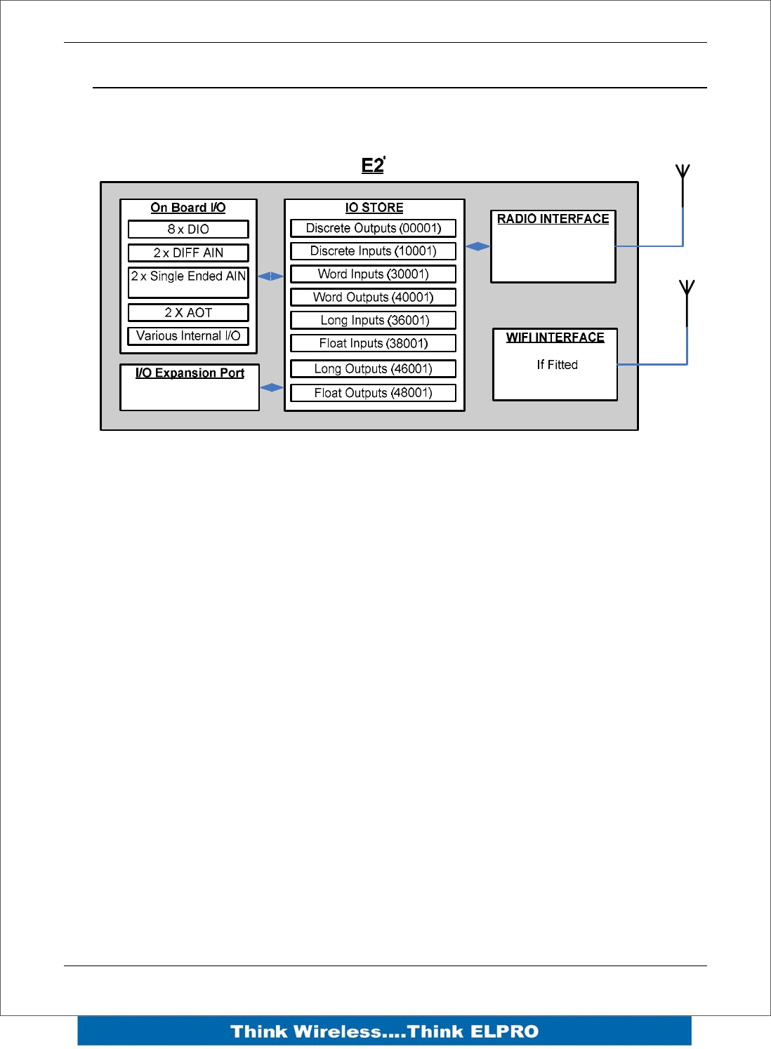
2.2 Power/Supply
The E2 power supply is of switch-mode design and will accept a 15 - 30 volt DC power
source connected to the “Sup + & Sup -” terminals.
• Note: AC supply requires external rectifier board and Solar requires and External
regulator for charging of battery.
Power Supply rating will depend a
whether the module has expansion I/O
modules connected and if a backup
battery is being used.
Allow 500mA for the radio, 200mA for
the module 1 Amp if expansion I/O
modules (115S) connected and 1 Amp
if a battery is connected and requires
charging.
E.g. If no battery or expansion I/O
modules are connected then the minimum current requirement will be 700mA @13,8V.
If I/O modules are connected and a backup battery is required then the minimum
current requirement will be approximately 2.7Amps @13.8V.
The power supply should be CSA Certified Class 2 approved for normal operation and
if being used in Class 1 Div 2 explosive areas, the power supply must be approved for
this area.
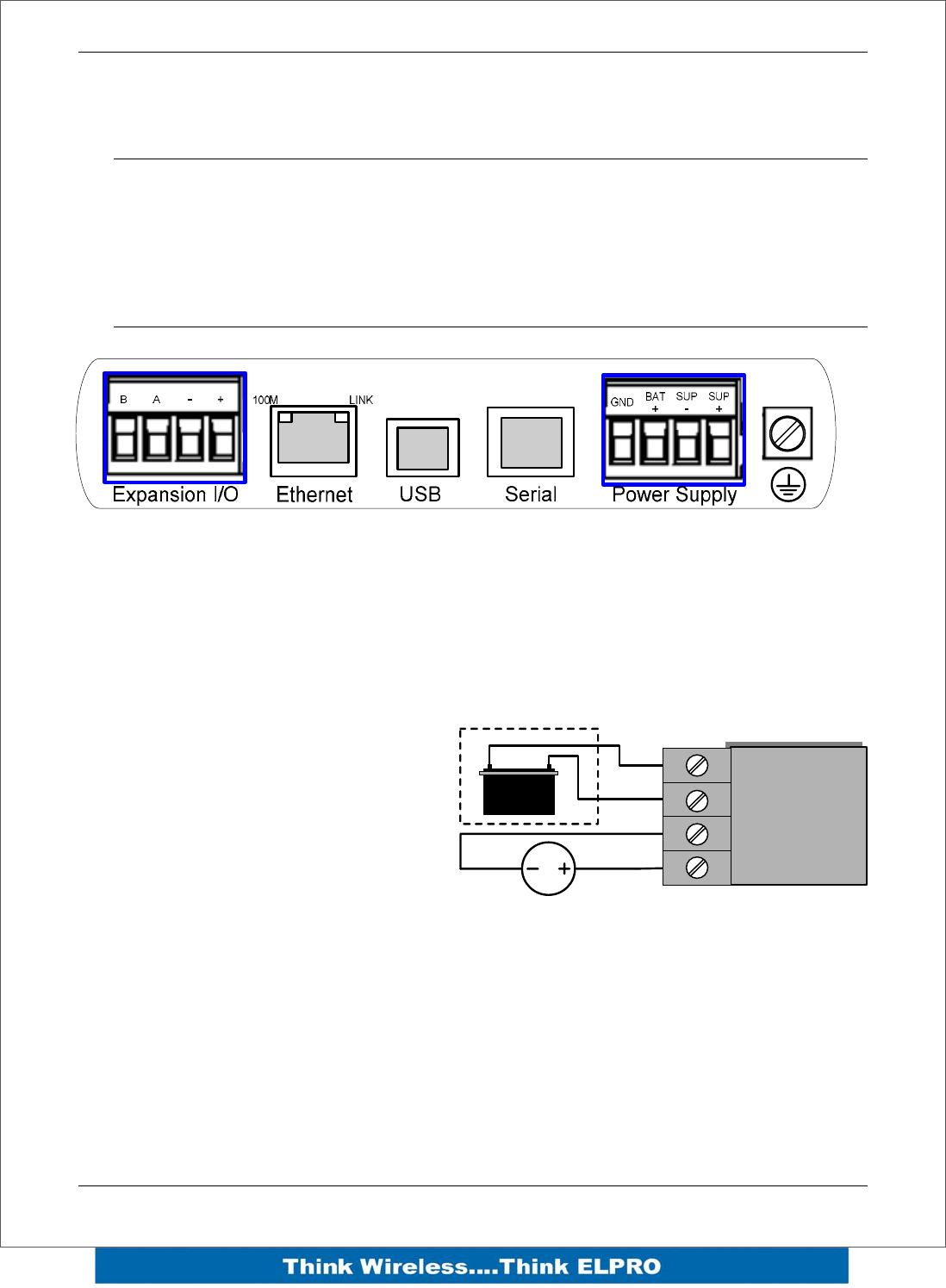
Automatic charging of a 13.8V Sealed Lead-Acid battery connected to the “BAT+” and
“GND” terminals at up to 1A.
SUP -
SUP +
POWER SUPPLY
GND
BAT +
15-30V DC Supply
+
_
External “Sealed Lead
Acid” battery if required
E2 Wireless I/O Page 13
The power supply input and battery charging are hosted on a 4-way terminal on the
bottom edge of the module labeled “Power Supply”.
To allow increased I/O Capacity, a second 4-way terminal labeled “Expansion I/O”
provides a +12 Volt supply and RS485 communications for any 115S serial expansion
I/O modules.
Up to three 115S-11, one 115S-12, or one 115S-13 may be powered by the Expansion
I/O Power Connection
The onboard power supply provides up to 1 Amp for battery charging, and up to 1 Amp
to supply I/O modules.
2.3 Radio
The following radio variants are available in the E2 dependent on the country of
operation.
900 MHz Spread Spectrum radio
The radio operates in the 902-928 MHz ISM band and uses frequency hopped spread
spectrum modulation, which is a method of transmitting radio signals by rapidly
switching the carrier among many frequency channels, using a pseudorandom
sequence known to both transmitter and receiver.
There are eight different pseudo random sequences known as “Hops sets”. Each Hop
set uses 50 channels and steps through these channels after every transmission.
The receiver is continually scanning all 50 channels and when a valid data packet is
heard it locks on to the channel and receives the data.
A spread-spectrum transmission offers some advantages over a fixed-frequency
transmission. These are - Spread-spectrum signals are more resistant to narrowband
interference, they are difficult to intercept or eavesdropper because of the
pseudorandom transmission sequences and transmissions can share a frequency band
with other types of conventional transmissions with minimal interference.
BA-+
E2 Expansion
I/O
BA-+
115S- XX
BA-+
115S- XX

Page 14 E2 Wireless I/O
Meshing capability
The ELPRO WIBMesh protocol is based on the “Ad hoc On Demand Distance Vector”
(AODV) routing algorithm which is a routing protocol designed for ad hoc networks.
AODV is capable of unicast and multicast routing and is an on demand algorithm,
meaning that it builds and maintains these routes only as long as they are needed by
the source devices.
The Protocol creates a table, which shows the connection routes to other device in the
system. The Protocol uses sequence numbers to ensure the routes are kept as current
as possible. It is loop-free, self-starting, and can scale to a large numbers of nodes.
See section 3.4 “WIBMesh” for more details on configuration.

E2 Wireless I/O Page 15
2.4 Antenna
The E2 module will operate reliably over large distances. The distance, which may be
reliably achieved, will vary with each application - depending on the type and location of
antennas, the degree of radio interference, and obstructions (such as hills or trees) to
the radio path.
Typical reliable distances are detailed below however longer distances can be achieved
if antennas are mounted in elevated locations – such as on a hill or on a radio mast.
Using the 900 MHz spread Spectrum radio the distances achievable will be:
USA/Canada 15 miles 6dB net gain antenna configuration permitted (4W ERP)
Australia/NZ 12 km Unity gain antenna configuration (1W ERP)
To achieve the maximum transmission distance, the antennas should be raised above
intermediate obstructions so the radio path is true “line of sight”. Because of the
curvature of the earth, the antennas will need to be elevated at least 15 feet (5 metres)
above ground for paths greater than 3 miles (5 km). The modules will operate reliably
with some obstruction of the radio path, although the reliable distance will be reduced.
Obstructions, which are close to either antenna, will have more of a blocking effect than
obstructions in the middle of the radio path. For example, a group of trees around the
antenna is a larger obstruction than a group of trees further away from the antenna.
The E2 module provides a range of test features, including displaying the radio signal
strength. Line-of-sight paths are only necessary to obtain the maximum range.
Obstructions will reduce the range however, but may not prevent a reliable path. A
larger amount of obstruction can be tolerated for shorter distances. For very short
distances, it is possible to mount the antennas inside buildings. An obstructed path
requires testing to determine if the path will be reliable - refer the section 6 of this
manual. Where it is not possible to achieve reliable communications between two
modules, then a third module may be used to receive the message and re-transmit it.
This module is referred to as a repeater. This module may also have input/output (I/O)
signals connected to it and form part of the I/O network - refer to Chapter 4
Configuration of this manual.
An antenna should be connected to the module via 50 ohm coaxial cable (e.g. RG58,
RG213, Cellfoil, etc) terminated with a male SMA coaxial connector. The higher the
antenna is mounted, the greater the transmission range will be, however as the length
of coaxial cable increases so do cable losses. For use on unlicensed frequency
channels, there are several types of antennas suitable for use. It is important antennas
are chosen carefully to avoid contravening the maximum power limit on the unlicensed
channel - if in doubt refer to an authorised service provider.
The net gain of an antenna/cable configuration is the gain of the antenna (in dBi) less
the loss in the coaxial cable (in dB).
Page 16 E2 Wireless I/O
At 900MHz the maximum net gain of the antenna/cable configuration permitted is
Country Max. Gain (dB)
USA / Canada 6
Australia / New Zealand 0
Europe 0
At 900MHz the gains and losses of typical antennas are
Antenna Gain (dB)
Dipole with integral 15’ cable 0
5dBi Collinear (3dBd) 5
8dBi Collinear (6dBd) 8
6 element Yagi 10
9 element Yagi 12
16 element Yagi 15
Cable type Loss (dB per 30 ft / 10 m)
RG58 -5
RG213 -2.5
Cellfoil -3
The net gain of the antenna/cable configuration is determined by adding the antenna
gain and the cable loss. For example, a 6 element Yagi with 70 feet (20 metres) of
Cellfoil has a net gain of 4dB (10dB – 6dB).
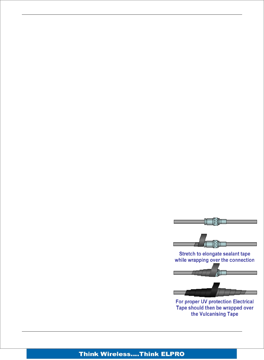
Connections between the antenna and coaxial cable
should be carefully taped to prevent ingress of
moisture. Moisture ingress in the coaxial cable is a
common cause for problems with radio systems, as it
greatly increases the radio losses. We recommend that
the connection be taped, firstly with a layer of PVC
Tape, then with a vulcanising tape such as “3M 23
tape”, and finally with another layer of PVC UV
Stabilised insulating tape. The first layer of tape allows
the joint to be easily inspected when trouble shooting
as the vulcanising seal can be easily removed.
Where antennas are mounted on elevated masts, the
masts should be effectively earthed to avoid lightning
surges. For high lightning risk areas, surge suppression
devices between the module and the antenna are recommended. If the antenna is not
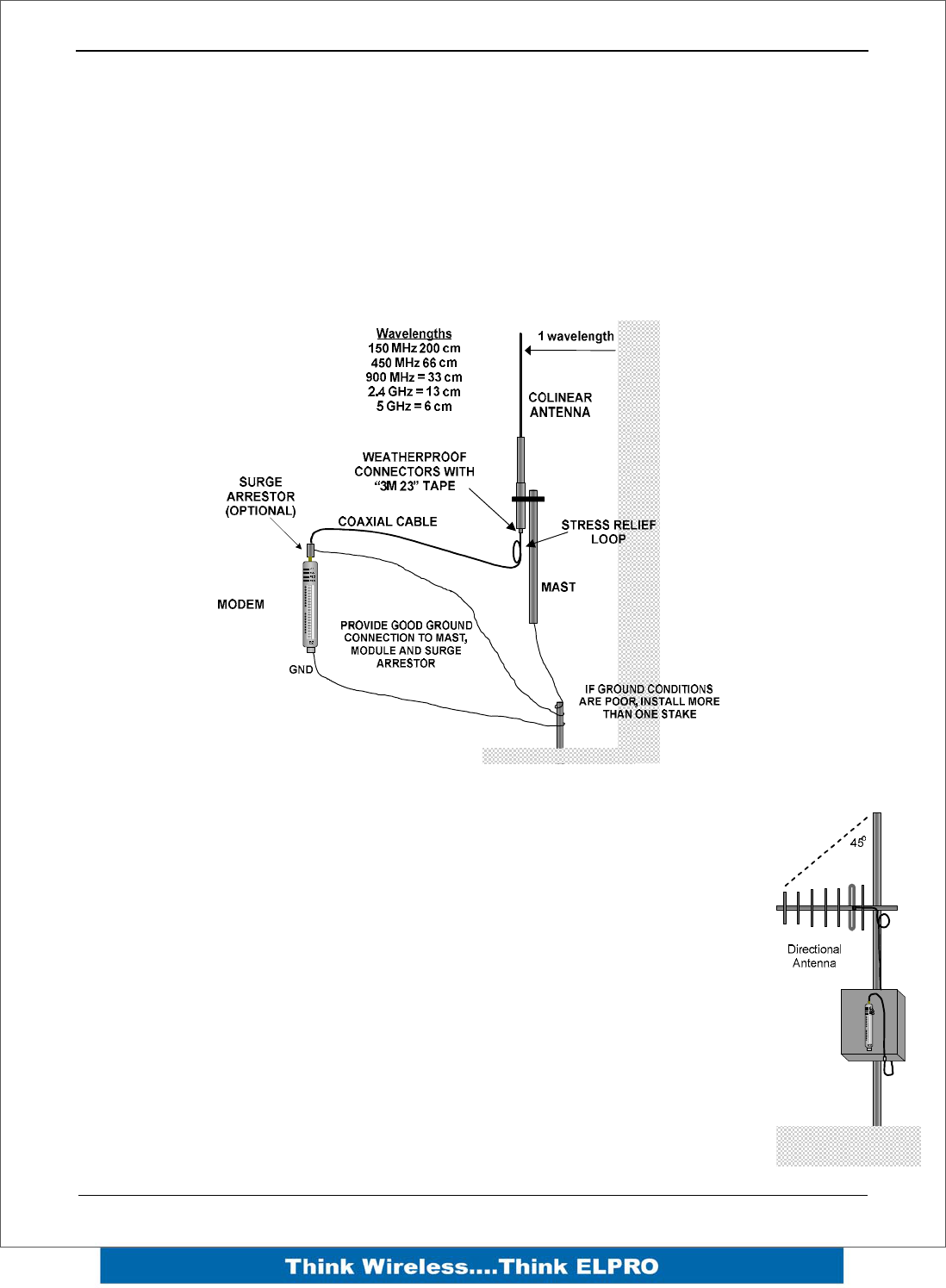
E2 Wireless I/O Page 17
already shielded from lightning strike by an adjacent earthed structure, a lightning rod
may be installed above the antenna to provide shielding.
Dipole and Collinear antennas.
A collinear antenna transmits the same amount of radio power in all directions - as such
they are easy to install and use. The dipole antenna with integral 15 ‘cable does not
require any additional coaxial cable; however a cable must be used with the collinear
antennas.
Collinear and dipole antennas should be mounted vertically, preferably 1 wavelength
(dependent on frequency) away from a wall or mast to obtain maximum range.
Yagi antennas.
A Yagi antenna provides high gain in the forward direction, but lower gain
in other directions. This may be used to compensate for coaxial cable loss
for installations with marginal radio path.
The Yagi gain also acts on the receiver, so adding Yagi antennas at both
ends of a link provides a double improvement.
Yagi antennas are directional. That is, they have positive gain to the front
of the antenna, but negative gain in other directions.
Hence, Yagi antennas should be installed with the central beam horizontal
and must be pointed exactly in the direction of transmission to benefit from
the gain of the antenna. The Yagi antennas may be installed with the
elements in a vertical plane (vertically polarised) or in a horizontal plane
(horizontally polarised). For a two-station installation, with both modules
using Yagi antennas, horizontal polarisation is recommended. If there are
more than two stations transmitting to a common station, then the Yagi
Page 18 E2 Wireless I/O
antennas should have vertical polarisation, and the common (or “central” station should
have a collinear (non-directional) antenna.
Also, note that Yagi antennas normally have a drain hole on the folded element - the
drain hole should be located on the bottom of the installed antenna.
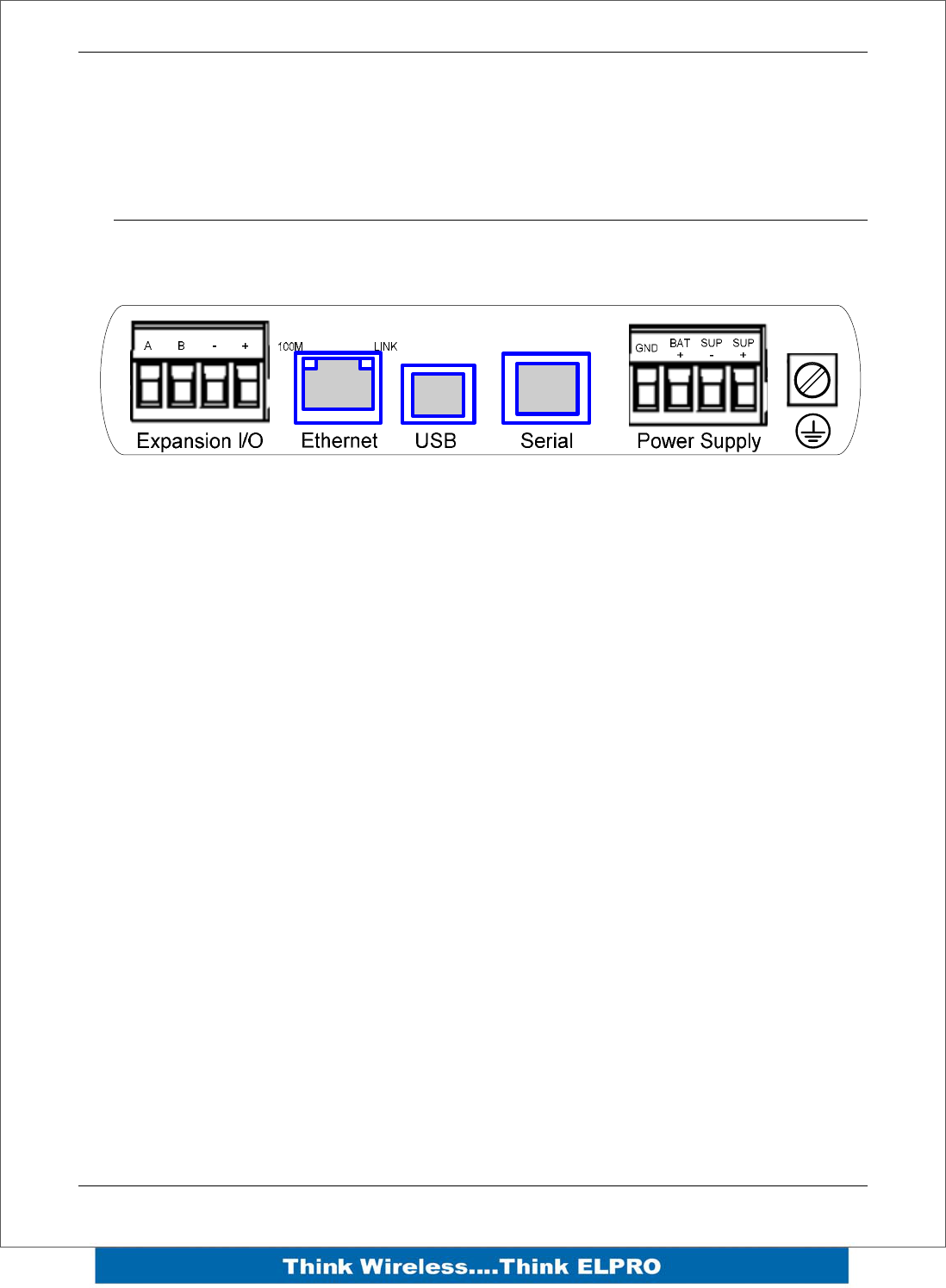
2.5 Connections
Bottom panel connections
Ethernet port
The E2 modules provides a standard RJ-45 Ethernet port compliant to IEEE 802.3
10/100 BaseT. This port provides full access to the module, including configuration,
diagnostics, log file download and firmware upload, of both the local and remote units.
Additionally the Ethernet port can provide network connectivity for locally connected
third-party devices with Ethernet functionality.
USB Device Port for configuration
The E2 module also provides a USB-device (USB-B) connector. This connector
provides configuration of the device and remote configuration access to other devices in
the radio network.
RS-232 port
The E2 module provides an RS-232 serial port, which support operations at data rates
up to 115,200 baud. This port supports MODBUS as well as “serial device server”,
bringing modem functionality to the E-Series products.
The RS-232 port is provided by an RJ-45 connector wired as a DCE according to EIA-
562.
E2 Wireless I/O Page 19
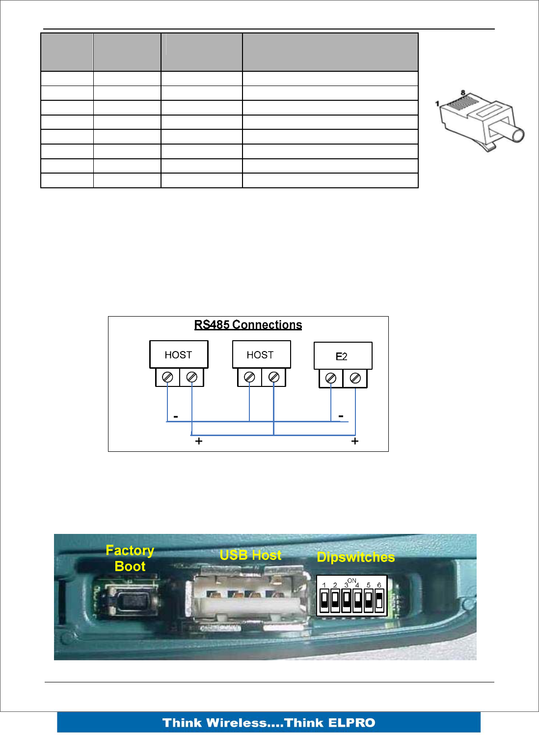
RS-485 port with Modbus Support.
The E2 module provides an RS-485 serial port, which support operations at data rates
up to 115,200 baud. This port Supports MODBUS functionality, as well as functionality
as “serial device server”, bringing modem functionality to the E-Series products
The RS-485 port is provided by two screw terminals. On-board termination of the RS-
485 circuit is built-in.
Side Access Configuration Panel
On the side of the module is a small access cover that hides a “Factory Boot” switch, a
USB Host port and a small bank of dipswitches that are used for Analog input
voltage/current selection, External Boot and Default configuration settings.
RJ-45 Signal
Name Required Signal name
1 RI Ring Indicator
2 DCD Data Carrier Detect
3 DTR Y Data Terminal Ready
4 GND Y Signal Common
5 RXD Y Receive Data (from Modem)
6 TXD Y Transmit Data (to Modem)
7 CTS Clear to Send
8 RTS Request to Send
Page 20 E2 Wireless I/O
“Factory Boot” switch
The “Factory Boot” switch is used to allow restoration of the firmware to a module that
has become non-functional. This switch should not normally be used, except if advised
by ELPRO support.
USB Host port
This port is a USB Host (Master port), which allows interface with a USB storage device
for data logging and for Firmware update to the module.
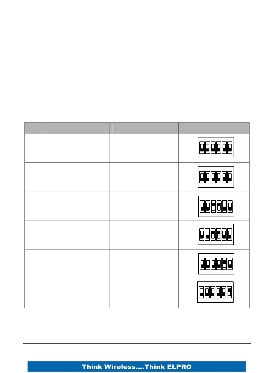
Dipswitch “Bank”
The Dipswitches are used to select a number of functions within the module; the table
below indicates switch positions.
DIP Off On Setting
1 AIN3 Voltage I/P AIN3 Current I/P
2 AIN3 Voltage I/P AIN3 Current I/P
3 AIN4 Voltage I/P AIN4 Current I/P
4 AIN4 Voltage I/P AIN4 Current I/P
5 Hardware Watchdog
Disabled Hardware Watchdog
Enabled
6 User Configuration
Active Default Configuration
Active
Dipswitches – 1 to 4 select if analog inputs 3 and 4 will be measuring Current or
Voltage. Set switches 1 and 2 OFF to measure voltage (0-5V) on Analog input 3. Set
switches ON to measure current on Analog input 3 (4-20mA). Set switches 3 and 4 OFF
1
ON
23456
1
ON
23456
1
ON
23456
1
ON
23456
1
ON
23456
1
ON
23456
E2 Wireless I/O Page 21
to measure voltage on Analog input 4. Set switches ON to measure current on Analog
input 4.
Dipswitch 5 – Factory use only. This switch should be set to ON to enable the hardware
watchdog protection feature.
Dipswitch 6 – When set to ON, the module will boot up with a known factory default
including a default IP address for Ethernet connection. (Refer to section 4.1)
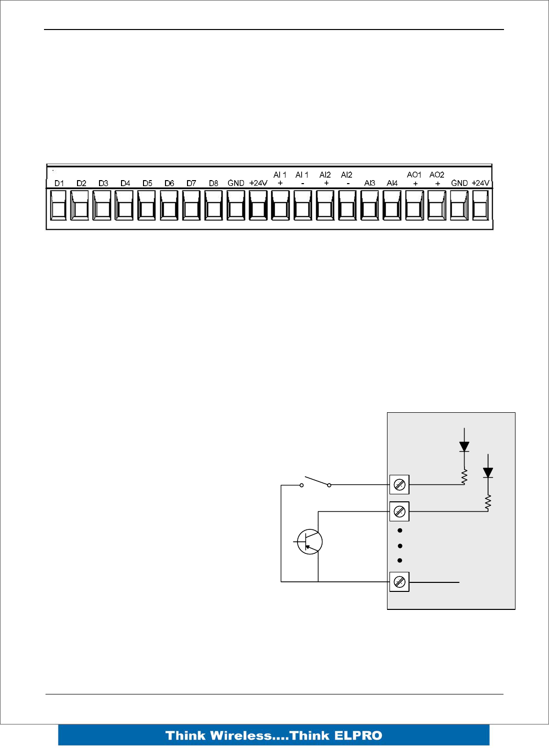
Front panel connections
The E2 front panel provides connections for eight Digital Input /Output (DIO1-8), two
“Floating” 16 bit, 0.1% accuracy differential analog inputs, two single ended 12 bit, 0.1%
accuracy analog inputs, two 15 bit, 0.1% accuracy current sourcing analog outputs and
connection terminals for Common and +24V Analog Loop Supply.
Digital Inputs
Each digital I/O channel on the E2 can act as either an input or an output. The
input/output direction is automatically determined by the connections and configuration
of the I/O.
If you have an I/O channel wired as an
input but operate the channel as an
output. No electrical damage will occur
however, the I/O system will not operate
correctly.
If operating the channel as an output
and performing a “read inputs” on this
location it will indicate the status of the
output.
Digital inputs signals share the same
terminals as the Digital output signals,
marked DIO1-8 on the E2 module.
A digital input is activated by connecting
the input terminal to EARTH or
Common, either by voltage-free contact
or by a transistor switch.
Voltage Free Contact
Transistor
Switch Device
V+
V+
V-
DIO1
DIO2
Common
E2 Module Inputs
Discrete Input / Output Used as input
Page 22 E2 Wireless I/O
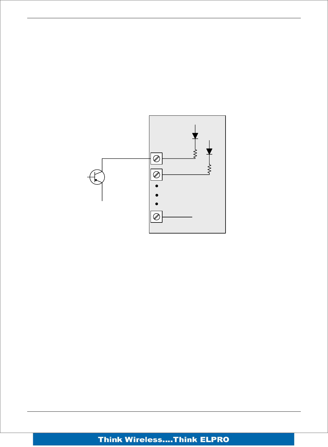
Pulsed Inputs
The E2 supports 8 digital signals, of which inputs 1-4 can be used as pulsed inputs.
The maximum pulse frequency is 50 KHz for Input 1 & 2 and 10 KHz for Input 3 & 4.
Digital/Pulsed inputs are suitable for voltage-free contacts, or NPN-transistor switch
devices.
Transistor
Switch Device
V+
V+
V-
DIO1
DIO2
Common
E2 Module Inputs
Pulsed Inputs
E2 Wireless I/O Page 23
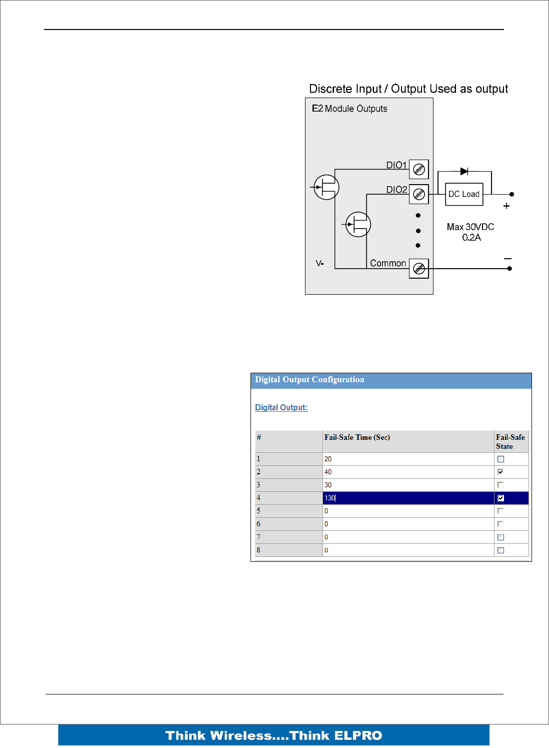
Digital Outputs (Pulsed Outputs)
Digital outputs are open-collector transistors and are able to switch loads up to 30VDC,
200mA.
The 8 digital outputs share the same
terminals as the digital input. These
terminals are marked DIO1-8.
When active, the digital outputs provide a
transistor switch to EARTH (Common).
To connect a digital output, refer to the
diagram across. A bypass diode is
recommended to protect against switching
surges for inductive loads such as relay
coils.
The digital channels DIO1-8 on the E2
module can be used as pulse outputs with a
maximum output frequency of 10KHz.
As well as indicating the Digital Output status (on / off), the LEDs can also indicate a
Fail Safe status by flashing the Output LED. This feature can be utilised by configuring
a Fail Safe time and status on the “I/O Configuration” web page as shown below.
The output will reflect the status on
the input which is done using a
Change of State message and an
update message. We use these
update messages to establish if the
Output has not been updated and
can then trigger the Fail Safe State.
The output expects to receive an
update message at a regular interval
and if it fails to receive this message
after the said time can then activate
the Fail Safe State. The Fail Safe
Time is the time the output needs to
count down before activating the Fail
Safe state.
The recommend time configured should be a little more than twice the update time of
the input that is mapped to it.
This is because the countdown is restarted whenever it received an update so if we
send two updates and fail to receive both we can then put the output into a Failsafe
state.
Page 24 E2 Wireless I/O
The Failsafe state if ticked (ON) will indicate with the LED being on and briefly flicking
off.
The Failsafe state if un-ticked (OFF) will indicate with the LED being off and briefly
flicking on.
Analog Inputs
The E2 provides two floating differential analog inputs and two grounded single-ended
analog inputs.
Analog Input 1 & 2 can be configured to measurement current (0-20 mA) or Voltage (0-
25V).
Analog input 3 & 4 can be configured to measure current (0-20mA) or voltage (0-5V).
An internal 24V analog loop supply (ALS) provides power for any current loops with a
maximum current limit of 175mA.
The LEDs have an analog diagnostic function and will indicate the status of the input.
If the current is less than 3.0 mA the LED will be off and if greater than 20.5mA the LED
will be on (Depending on scaling).
The LED will flicker with the duty cycle relative to the analog reading in this range. (Note
by default there is a 5 second delay on the input because of the Filter)
LEDs beside AI1+, AI2+ flash according to current on these inputs. LEDs beside AI1-
and AI2- flash according to the voltage on the Analog inputs.
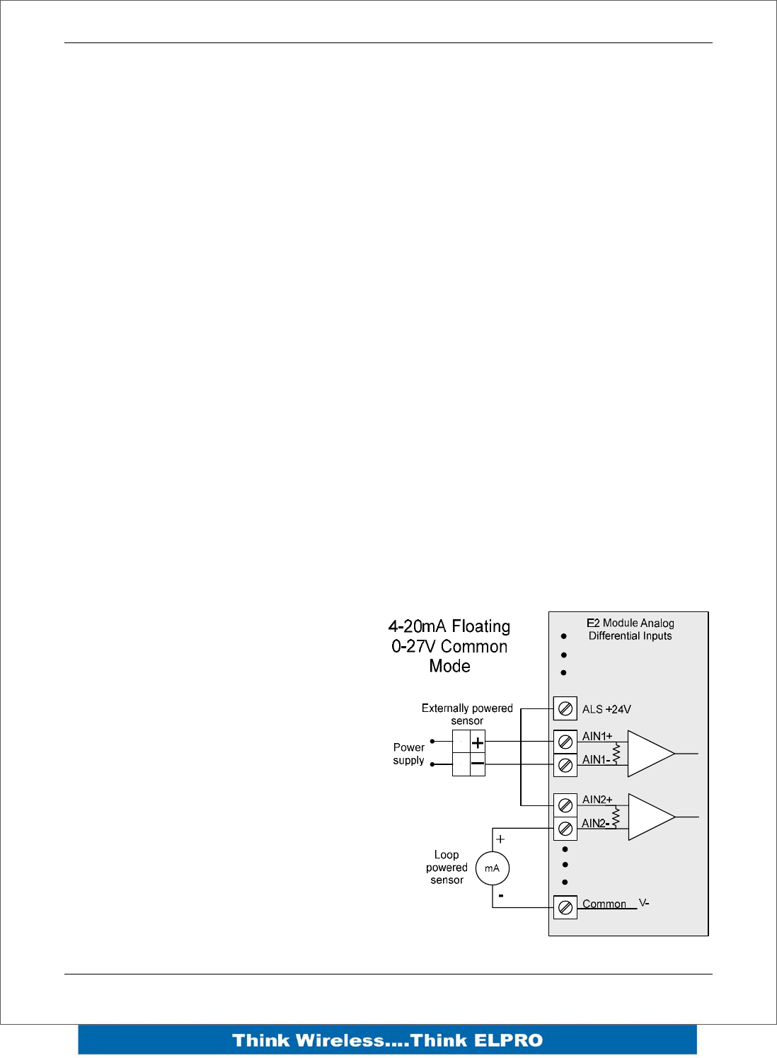
Floating Differential Analog Inputs (AIN 1 & 2 only)
Differential mode current inputs should
be used when measuring a current loop,
which cannot be connected to earth or
ground. This allows the input to be
connected anywhere in the current loop.
Common mode voltage can be up to
27VDC.
The diagram across indicates how to
connect Loop powered or externally
powered devices to the E2 Differential
Inputs.
E2 Wireless I/O Page 25
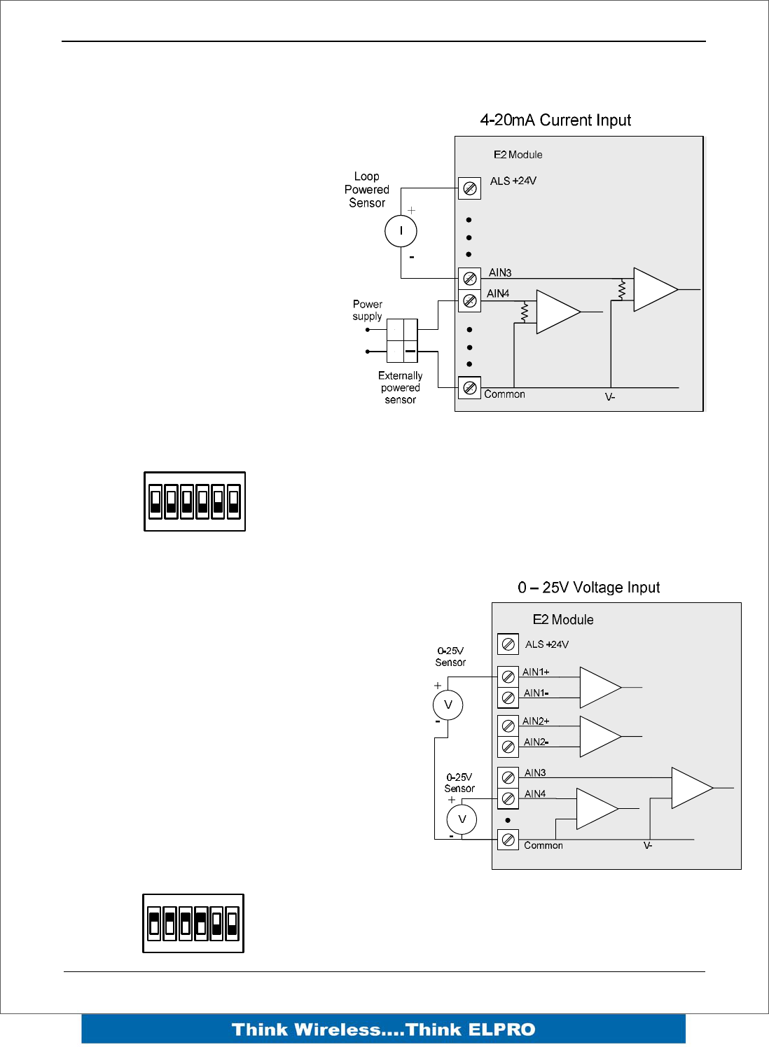
Single Ended Current Inputs (AIN 3 & 4 only)
Single-ended current input mode is
useful if the sensor loop is
grounded to the E2 module.
Devices can be powered externally
from the 24V Analog Loop Supply
supplied internally within the
module.
The Dip Switches are used to
determine if the inputs will be
current or voltage. .
Dip Switches 1 & 2 are used for or
Analog 3 and Dip Switches 3 & 4
are used for Analog 4
For Current set both Dip Switches
to the “On” position, for Voltage set
both to “Off”
Refer below for Dipswitch settings
when both analog inputs 3&4 are used for current
Single Ended Voltage Inputs
All analog inputs can be setup to read
voltage.
If using Analog input 1 & 2 connect the
voltage source across the positive terminal of
the input and Common.
If using Analog input 3 & 4 then connect
across the input terminal and Common.
Note: default scaling gives 0-10V for 4-20mA
output
If using Analog input 3 & 4 for Voltage set
both Dip Switches to the “Off” position,
Analog input 1 &2 do not require switch
setup.
DIP switch settings used for voltage
+
1
ON
23456
1
ON
23456
Page 26 E2 Wireless I/O
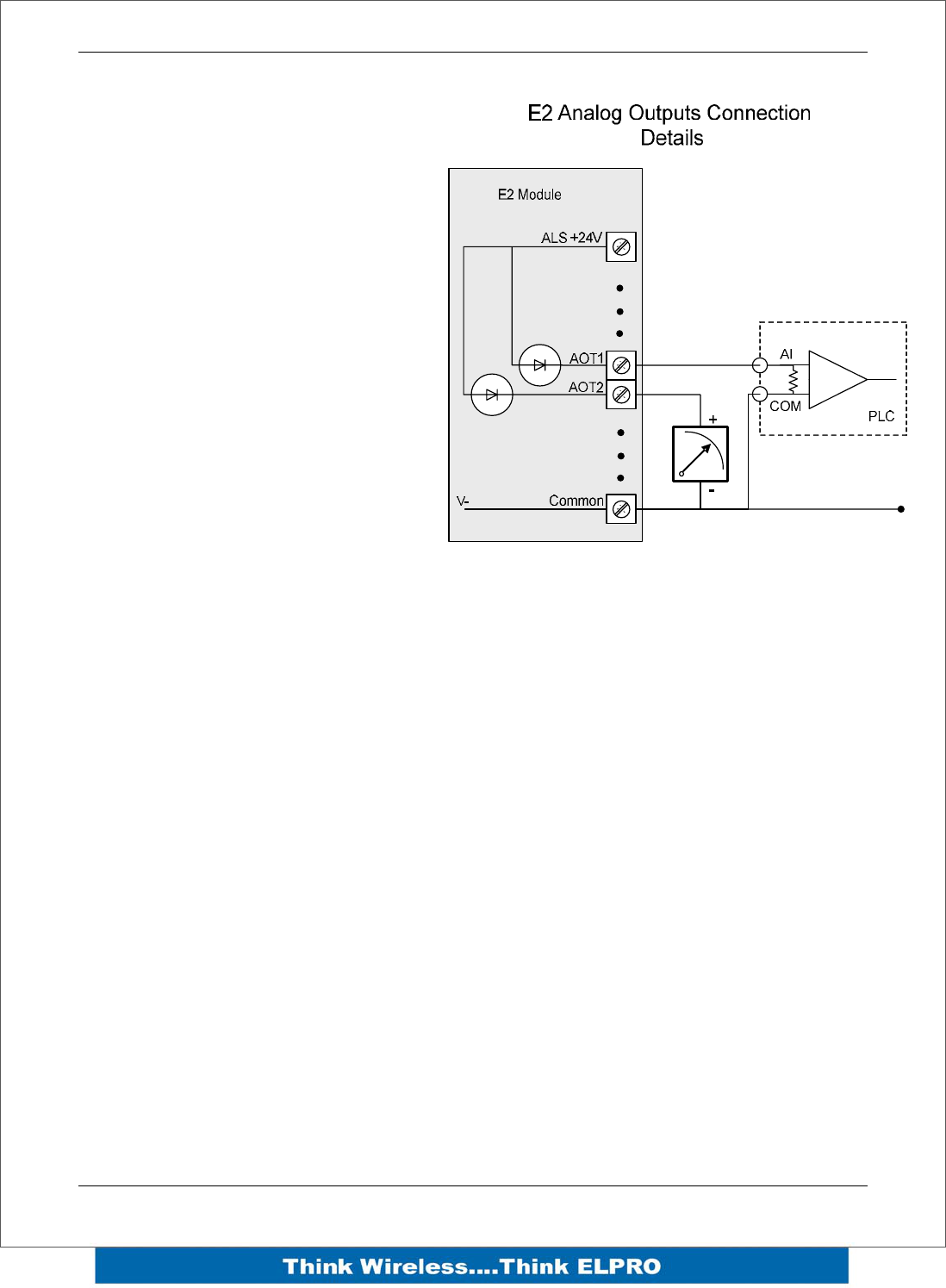
Analog Outputs
The E2 module provides two 0 - 24
mA DC analog outputs for
connecting to instrument indicators
for the display of remote analog
measurements.
The E2 Analog outputs are a
sourcing output and should be
connected from the analog output
terminal through the device or
indicator to Common. See diagram
for connections.
The LEDs function as a primitive
level indicator depending on current -
Dim for 4mA and Bright for 20mA

E2 Wireless I/O Page 27
3Chapter 3 – Operation
3.1 Overview
The E2 range of I/O modules has been designed to provide standard “off-the-shelf”
telemetry functions, for an economic price. Telemetry is the transmission of data or
signals over a long distance via radio or twisted-pair wire cable.
3.2 Indications
When power is initially connected to the module it will go through an internal diagnostics
check where it will perform some internal setup and diagnostics checks to determine if
the module is operating correctly. These checks will take approximately 90 seconds.
The table below indicates the correct LED indications.
Front Panel Indications
LED
Indicator Condition Meaning
PWR GREEN System OK
PWR Fast Flash System Boot – Stage 1
PWR SLOW Flash System Boot – Stage 2
PWR RED System Failure
RF GREEN Receiving Radio data
RF RED Transmitting Radio data
232 GREEN Receiving RS232 data
232 RED Transmitting RS232 data
232 ORANGE Transmitting and Receiving RS232 data
485 GREEN Receiving RS485 data
485 RED Transmitting RS485 data

Page 28 E2 Wireless I/O
I/O Indications
LED
Indicator Condition Meaning
DIO 1-8 ORANGE Digital input ON
DIO 1-8 FLASHING ORANGE
– Mostly On Update Failure – Failsafe state On
DIO 1-8 FLASHING ORANGE
– Mostly Off Update Failure – Failsafe state Off
AI 1 & 2 #1 ORANGE Analog input current indication
AI 1 & 2 #2 ORANGE Analog input voltage indication
AI 1 & 2
FLASHING ORANGE Duty cycle relative to the analog reading
Slow =4mA, Fast=20mA
AI3 & 4 ORANGE Analog input current / voltage indication
AO1 & 2 ORANGE Analog output current indication
LED’s display the status of each of the eight digital inputs (If the LED is lit then the input
is on).
If the DIO are used as outputs then the LEDs will, display the status of each of the
digital output (If the LED is lit then the output is on).
Two LEDs exist for each Differential analog input (Channel 1 & 2). The first is used to
indicate the set point and the second whether the analogue input is reading zero or
negative.
For each of the single ended analog channels, the LED indicates when the analogue
input loop is in loop mode.
The two lowest Analog output LEDs are in series with the analog Output and will
indicate the output current. (Dim for 4mA Bright for 20mA).
Ethernet Indications
On the end plate, the ethernet socket incorporates two LED’s These LEDs indicating
the Ethernet status
100M – GREEN LED indicates presence of a 100 Mbit /s
Ethernet connection, with a 10 Mbit /s connection the LED will
be off.
LINK – ORANGE indicates an Ethernet connection and LED
briefly flashed off with ethernet activity.

E2 Wireless I/O Page 29
3.3 System Design Tips
System Dynamics

Page 30 E2 Wireless I/O
3.4 WIBMesh
The ELPRO WIBMesh protocol is based on the “Ad hoc On-demand Distance Vector”
(AODV) routing algorithm which is a routing protocol designed for ad hoc networks.
AODV is capable of unicast (single addressed message) and multicast (Broadcast to
all) routing and is an “on-demand” protocol, meaning that it builds and maintains these
routes only as long as they are needed by the source devices. Another words the
network is silent until a connection is needed. The Protocol creates a table, which
shows the connection routes to other device in the system and uses sequence numbers
to ensure the routes are kept as current as possible.
When a module in a network needs to make a connection to another module it
broadcasts a request for connection. Other modules forward this message, and record
the module address that they heard it from, creating a table of temporary routes back to
the starting module. If a module receives a message and it already has an existing
route to it, it will send a message backwards through the temporary route to the
requesting module.
Each request for a route has a sequence number. Modules use this sequence number
so that they do not repeat route requests that they have already passed on. Another
such feature is that the route requests have a "time to live" number that limits how many
times they can be retransmitted. Another such feature is that if a route request fails,
another route request may not be sent until twice as much time has passed as the
timeout of the previous route request.
The original starting module then begins using the route that has the least number of
hops. Unused entries in the routing tables are recycled after a time.
When a link fails, a routing error is passed back to a transmitting node, and the process
repeats.
E2 Wireless I/O Page 31
4Chapter 4 – Configuration
4.1 First time
The E2 has a built-in web server, containing web pages for analyzing and modifying the
module’s configuration. The configuration can be accessed using Microsoft® Internet
Explorer.
Default Configuration
The default factory configuration of the E2 is
IP address192.168.0.1XX, where XX is the last two digits of the serial number (the
default IP address is shown on the printed label on the back of the module)
netmask 255.255.255.0
Username is “user” and the default password is “user”
The E2 will temporarily load some factory-default settings if
powered up with the #6 dipswitch under the side configuration
panel switched on. When in SETUP mode, wireless operation is
disabled. The previous configuration remains stored in non-volatile
memory and will only change if a configuration parameter is
modified and the change saved.
Do not forget to set the switch back to the OFF position and re-cycle the
power at the conclusion of the configuration for normal operation otherwise, it
will continue to boot into the default IP address.
Accessing Configuration for the first time
The Default IP address is in the range 192.168.0.XXX
and so will require a PC on this network or be able to
change the network settings to access the module
configuration.
This is the procedure for changing A PC network
settings.
methods for accessing the configuration for the first
time.
You will need a “straight-through” Ethernet cable
between the PC Ethernet port and the E2. The factory
default Ethernet address for the E2 is 192.168.0.1XX
where XX are the last two digits of the serial number
(check the label on the back of the module).
Connect the Ethernet cable between unit and the PC
configuring the module.
Page 32 E2 Wireless I/O
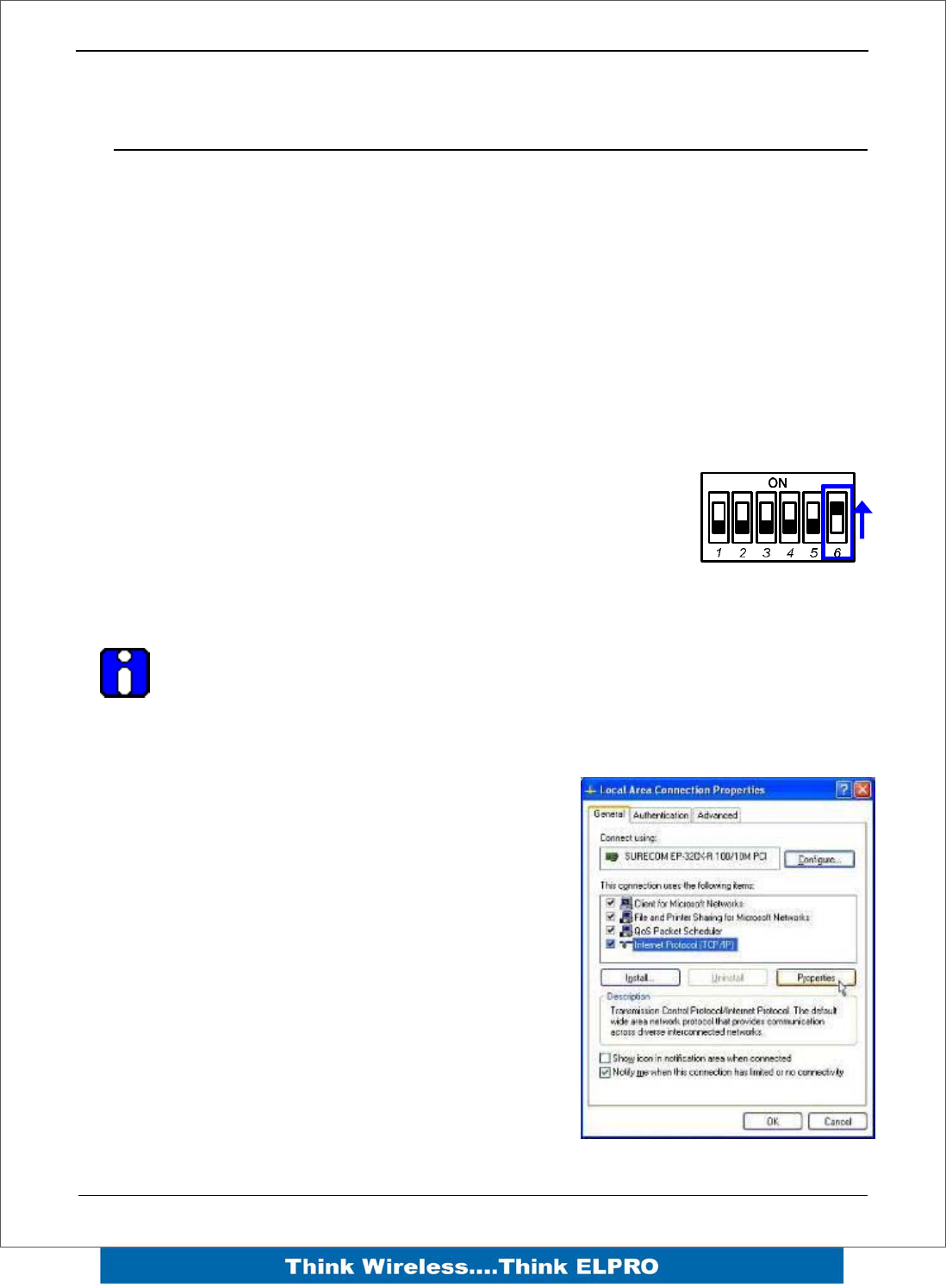
Open the side configuration panel and set the #6 Dipswitch to ON Switch to the ON
position. This will always start the E2 with Ethernet IP address 192.168.0.1XX, subnet
mask 255.255.255.0, gateway IP 192.168.0.1 and the radio disabled. Do not forget to
set the switch back to the OFF position and restart the module at the conclusion of
configuration.
Power up the E2 module.
Open “Network Settings” on your PC under Control Panel. The following description is
for Windows XP - earlier Windows operating systems have similar settings.
Open “Properties” of Local Area Connection.
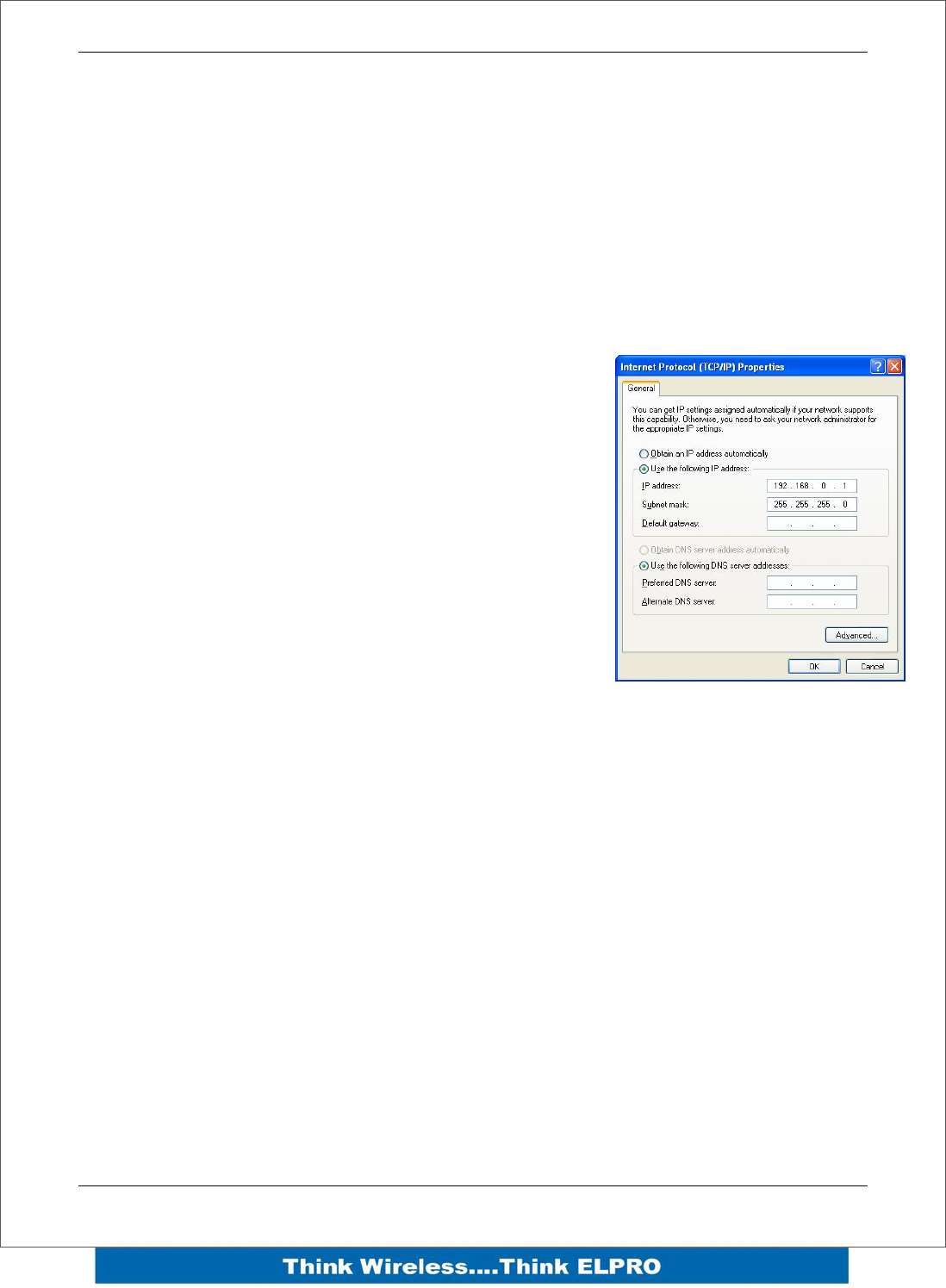
Select Internet Protocol (TCP/IP) and click on Properties.
On the General tab enter IP address 192.168.0.1, Subnet
mask 255.255.255.0 and press “OK”
Open Internet Explorer and ensure that settings will allow
you to connect to the IP address selected. If the PC uses
a proxy server, ensure that Internet Explorer will bypass
the Proxy Server for local addresses.
This option may be modified by opening Tools -> Internet
Options -> Connections Tab -> LAN Settings->Proxy
Server -> bypass proxy for local addresses.
Enter the default IP address for the E2
https://192.168.0.1XX where XX is the last two digits of
the serial number.
Enter the username “user” and default password “user”.
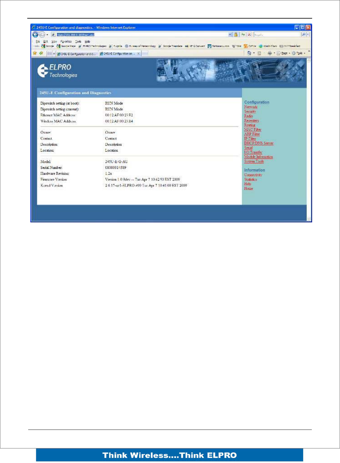
E2 Wireless I/O Page 33
Figure 1 – Welcome Webpage
To resume normal configured operation when Configuration is complete, switch Factory
Default dip-switch on the E2 to RUN and cycle power.
Note: Security Certificates. Configuration of the E2 uses an encrypted link (https). The
security certificate used by the E2 is issued by ELPRO and matches the IP address
192.168.0.100.
When you first connect to the E2, your web browser will issue a warning that ELPRO is
not a trusted authority. Ignore this warning and proceed to the configuration web page.
To avoid seeing this warning in future, you can install the certificate into your browser.
Internet Explorer 7 has an additional address check on security certificates. Unless the
E2 has the address 192.168.0.100, when you first connect to the E2, Internet Explorer
7 will issue a warning about mismatched security certificate address. You can turn off
this behaviour in IE7 by selecting
“Tools > Internet Options > Advanced > Security > Warn about certificate address
mismatch*”

Page 34 E2 Wireless I/O
4.2 Network Configuration
You can view or modify Ethernet network parameters by selecting the “Network” menu.
When prompted for username and password, enter “user” as the username, and “user”
as the password in the password field (This is the factory default – See section 4.8
“Module Information” to change). If you have forgotten the IP address or password, the
Factory Default switch may be used to access the existing configuration. Refer to
section above for this procedure.
The Network Configuration page allows configuration of parameters related to the wired
and wireless Ethernet interfaces. In general, IP address selection will be dependant
upon the connected wired Ethernet device(s) – before connecting to an existing LAN
consult the network administrator.
Device Mode
Default Gateway This is the address that the device will use to forward
messages to remote hosts that are not connected to any of
the local bridged network (Ethernet or Wireless). This is only
required if the wired LAN has a Gateway unit which connects
to devices beyond the LAN - for example, Internet access. If
there is no Gateway on the LAN, set to the same address as
the “Ethernet IP Address” below.
Obtain IP Address
Automatically Checking this item enables DHCP client on the E2. A DHCP
client requests its IP address from a DHCP server, which
assigns the IP Address automatically. Default is unchecked.
Ethernet Interface
MAC Address This is the unique hardware address of the E2 and is
assigned in the Factory. The E2 has two MAC addresses,
one for each interface (Ethernet and Wireless) The Ethernet
MAC is the primary MAC Address.
IP Address The IP address of the E2 on its wired (Ethernet Interface) port
and wireless (Wireless Interface) port. This should be set to
the IP address you require. If the device mode is set to
bridge, then the wired and wireless ports will have the same
IP address.
IP Subnet Mask The IP network mask of the E2 on its wired (Ethernet
Interface) port and wireless (Wireless Interface) port. This
should be set to appropriate subnet mask for your system
(Typically 255.255.255.0).

E2 Wireless I/O Page 35
Radio Interface
IP Address The IP address of the E2 on its wired (Ethernet Interface) port
and wireless (Wireless Interface) port. This should be set to
the IP address you require. If the device mode is set to
bridge, then the wired and wireless ports will have the same
IP address.
IP Subnet Mask The IP network mask of the E2 on its wired (Ethernet
Interface) port and wireless (Wireless Interface) port. This
should be set to appropriate subnet mask for your system
(Typically 255.255.255.0).
Save Changes Save changes to non-volatile memory. The module will need
to be restarted before the changes take effect.
Save Changes and
Reset. Save settings to non-volatile memory, and reboot E2. Once
the module has completed the reboot sequence, all changes
are in effect.
4.3 Radio Settings
The E2 can be configured for different radio transmission rates. A reduction in rate
increases the reliable range (transmission distance). The factory-default data rate
settings are suitable for the majority of applications and should only be modified by
experienced users.
The E2 allows for configurable fixed or fallback radio transmission Data Rates. When a
fixed rate is configured, the radio transmission rate is never altered, even under
extremely poor conditions. The fallback rates allow a maximum rate to be configured
whilst enabling the unit to automatically reduce the rate when transmit errors occur.
When a radio transmission is unsuccessful, the E2 will automatically drop to the next
lowest data rate and enter probation. If subsequent transmissions are successful at the
lower rate, the E2 will attempt to increase to the next highest rate when probation has
ended. When a station connects to an access point the two devices negotiate a data
rate based which is within configured range of radio data rates for both devices. If there
is no common data rate, then the devices will not be able to connect.
Select the “Radio” Menu to change the following configuration parameters. If a change
is made, you need to select “Save Changes” to retain the changes. Changes will not
take effect until the unit is reset.

Page 36 E2 Wireless I/O
Radio Settings
Transmit Power
Level This allows adjustment of the radio power. Do not set the
radio power above the allowed setting for your country You
can reduce the power for short range applications, or to
allow the use of high gain transmitter antennas while still
complying with the emission requirements of your country.
See “Appendix D” for dBm to mW conversion
Transmit Data Rate • The radio baud rate in Mega (million) bits per second
(Mbps) for point to point radio transmissions. The
default value is Auto. Select a fixed rate to force the
radio to use the selected rate. Select a fallback rate
to allow the radio to select a lower rate if there are
communications problems. Normally an Access point
is configured with either auto or a fallback data rate to
allow clients to connect with different data rates.
Channel Select available channel, frequency and bandwidth from
drop down list. Australia only has 1 channel available
(Channel 41).
Radio Channels 1 to 11 may be configured at the Access
Point. Default radio channel is set to 3.
Save Changes Save changes to non-volatile memory. The module will need
to be restarted before the changes take effect.
Save Changes and
Reset. Save settings to non-volatile memory, and reboot E2. Once
the module has completed the reboot sequence, all
changes are in effect.
E2 Wireless I/O Page 37
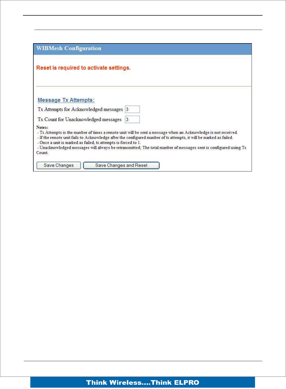
4.4 WIBMesh Configuration
The “TX Attempts for Acknowledged messages” is now many times the configured
module will attempt to communicate a message to another module (message reties).
After failing to communicate the module will be flagged as being in comms fail.
Every time it tries to communicate to the remote module, it will reduce the number of
attempts down to one as it has been flagged as being in Comms fail.
If communications is restored the module will go back to transmitting the number of
time configured in “Tx Attempts for Acknowledged messages”.
The “TX count for unacknowledged messages” is the number of times it transmit the
same data message. It is used if the E2 has been setup as a transmit only module
(similar to the older Elpro 905U-K or 505U-K modules)
Being a Transmit only module there is no communication handshake between modules
so transmitting the same message a number of times gives a greater reliability in
communications.
Page 38 E2 Wireless I/O
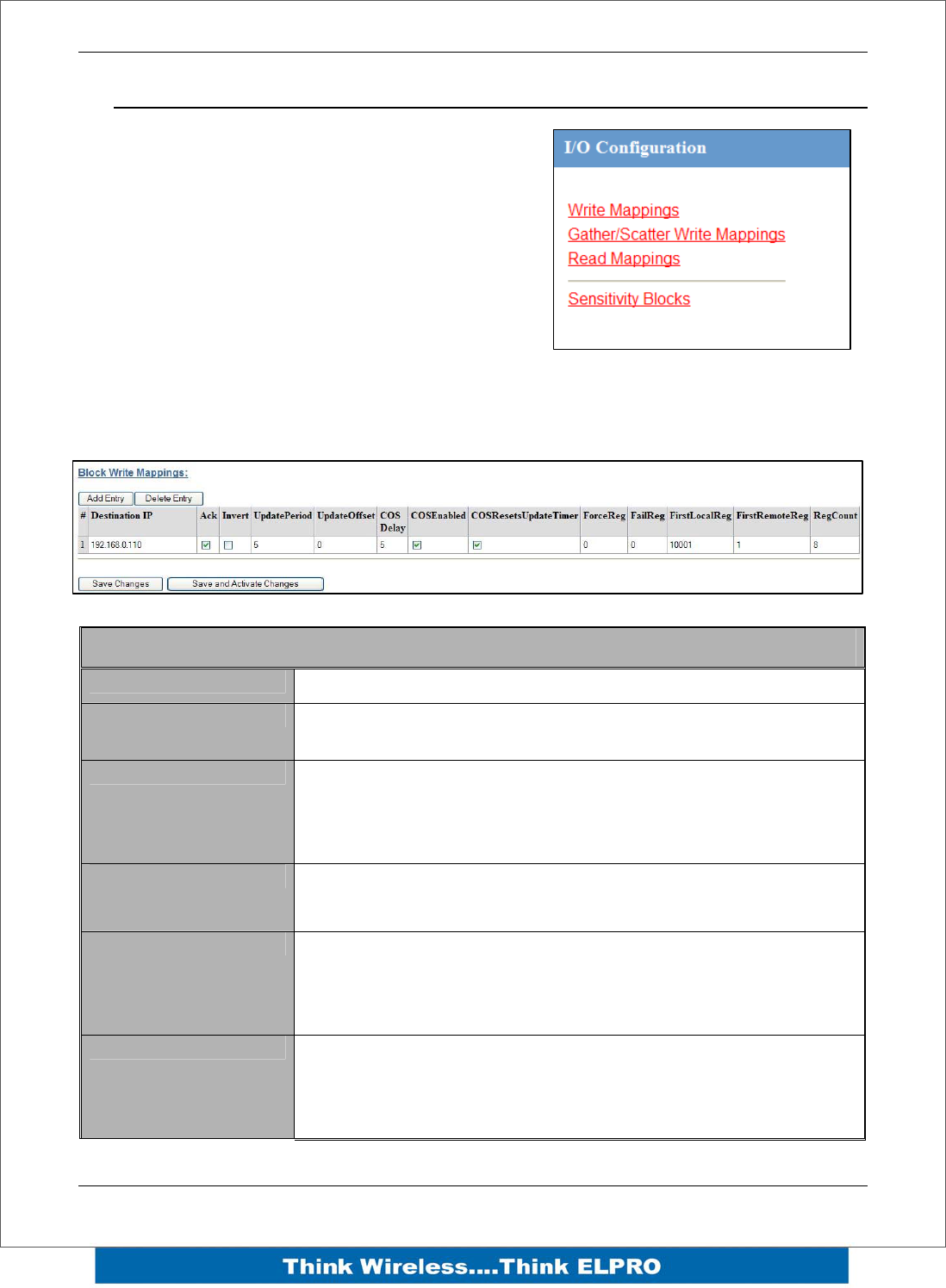
4.5 WIBMesh Mappings
Selecting WIBMesh Mappings from the right hand
side of the main menu will show the I/O
Configuration screen.
This is where you configure Read, Write and
Gather/Scatter mappings as well as any Sensitivity
Blocks.
Write Mappings
Add or delete mapping by using the buttons then select “Save and Activate Changes”.
Block Write Mapping
Destination IP This is the IP address that you wish to write the I/O to.
Ack Selecting this box will mean the mapping will be
acknowledged
Invert This will allow the mapping to be inverted. E.g. if the digital
input is on and inverted then the output will be off and visa
versa. Applies to all the I/O in the mapping and can only be
used with Words and Bits, No Floating Point or Long values
Update Period This is the period that the mappings are sent as an update or
check signal.
Update Offset Allows an offset to be configured for each mapping. Used to
stagger the transmissions so on start-up the module does not
try to send all mapping at the same time. Default it will be 0
however the normal would be around 10 minutes
COS Delay You can enter a delay period such that the message is
delayed from sending for the configured time. Used to hold
off the transmissions to allow more COS (Change of State)
messages to be added to the mapping.
E2 Wireless I/O Page 39
COS Enabled Can enable or disable the COS message. If disabled
messages would only be sent on the update period.
COS Resets Update
Timer Enabling this timer will mean If a COS is received in between
update messages it will reset the Update timer, meaning it will
not receive another update until the further Update period has
passed.- used to reduce the amount of radio traffic
Force Reg Register location that when written to will force the Write
Mapping to be sent. E.g. External device can initiate the
transmissions.
Fail Reg Register location that will indicate a failure to communicate
with the remote Destination Address configured
First Local Reg Starting Local address that values will be written to.
First Remote Reg Starting Remote address that the values will read from.
Reg Count Total number of register values (consecutive)
Save Changes Save changes to non-volatile memory. The module will need
to be restarted before the changes take effect.
Save Changes and
Reset. Save settings to non-volatile memory, and reboot E2. Once
the module has completed the reboot sequence, all changes
are in effect.
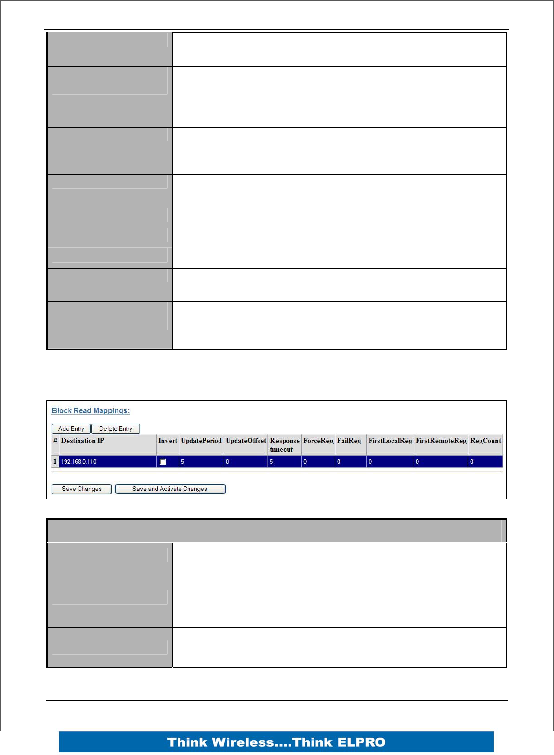
Read Mappings
Block Read Mapping
Destination IP This is the Module IP address that you wish to read I/O from.
Invert
This will allow the mapping to be inverted. E.g. if the digital
input is on and inverted then the output will be off and visa
versa. Applies to all the I/O in the mapping and can only be
used with Words and Bits, No Floating Point or Long values
Update Period This is the period that the mappings are sent as an update or
check signal.
Page 40 E2 Wireless I/O
Update Offset
Allows an offset to configured for each mapping. Used to
stagger the transmissions so on start-up the module does not
try to read all mapping at the same time. Default it will be 0
however the normal would be around 10 minutes
Response Timeout Time before a response Failure is registered
Force Reg
Register location that when written to will force the Read
Mapping to be sent. E.g. External device can initiate the
transmissions.
Fail Reg Register location that will indicate a failure to communicate
with the remote Destination Address configured
First Local Reg Starting Local address that values will be written to.
First Remote Reg Starting Remote address that the values will read from.
Reg Count Total number of register values (consecutive)
Save Changes Save changes to non-volatile memory. The module will need
to be restarted before the changes take effect.
Save Changes and
Reset.
Save settings to non-volatile memory, and reboot E2. Once
the module has completed the reboot sequence, all changes
are in effect.
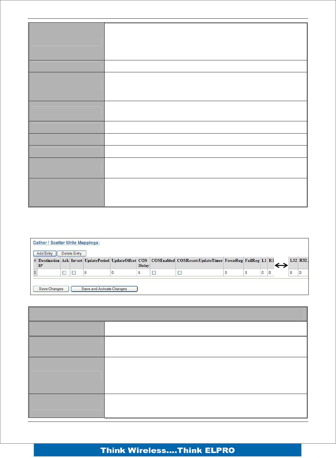
Gather/Scatter Write Mappings
Gather/Scatter Write Mapping
Destination IP This is the Module IP address that you wish to read I/O from.
Ack Selecting this box will mean the mapping will be
acknowledged
Invert
This will allow the mapping to be inverted. E.g. if the digital
input is on and inverted then the output will be off and visa
versa. Applies to all the I/O in the mapping and can only be
used with Words and Bits, No Floating Point or Long values
Update Period This is the period that the mappings are sent as an update or
check signal.

E2 Wireless I/O Page 41
Update Offset
Allows an offset to configured for each mapping. Used to
stagger the transmissions so on start-up the module does not
try to send all mapping at the same time. Default it will be 0
however the normal would be around 10 minutes
COS Delay You can enter a delay period such that the message is
delayed from sending for the configured time. Used to hold
off the transmissions to allow more COS messages to be
added to the mapping.
COS Enabled Can enable or disable the COS messaged. If disabled
messages would only be sent on the update period.
COS Resets Update
Timer Enabling this timer will mean If a COS is received in between
any updates it will reset the Update timer, meaning it will not
receive another update until the further Update period has
passed.- used to reduce the amount of radio traffic
Force Reg Register location that when written to will force the Write
Mapping to be sent. E.g. External device can initiate the
transmissions.
Fail Reg Register location that will indicate a failure to communicate
with the remote Destination Address configured
Reg Count Total number of register values (consecutive)
L1 & R2 – L32 & R32 Local and Remote pairs indicating up to 32 scattered local I/O
registers can be mapped to 32 remote I/O registers
Save Changes Save changes to non-volatile memory. The module will need
to be restarted before the changes take effect.
Save Changes and
Reset.
Save settings to non-volatile memory, and reboot E2. Once
the module has completed the reboot sequence, all changes
are in effect.
Page 42 E2 Wireless I/O
4.6 Serial Configuration
The E2 has an RS-232, and RS-485 port for serial communications. These ports may
be used to connect external Modbus RTU devices via the Modbus TCP to RTU
Gateway.
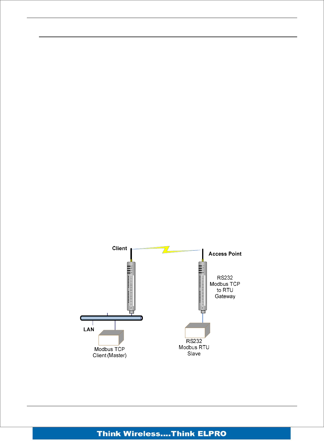
Modbus TCP to RTU Gateway
The Modbus TCP to RTU Gateway allows an Ethernet Modbus/TCP Client (Master) to
communicate with a serial Modbus RTU Slave. The E2 makes this possible by internally
performing the necessary protocol conversion. The conversion is always performed by
the E2, which is directly connected to the Modbus serial device (i.e. only this module
needs to have Modbus TCP to RTU Gateway enabled).
The example below demonstrates how a Modbus/TCP Client (Master) can connect to
one or more Modbus RTU (i.e serial) Slaves. In this example the E2 Access Point is
configured with the “RS232 Modbus/TCP to RTU Gateway” enabled.
Once enabled, the gateway converts the Modbus/TCP queries received from the
Master into Modbus RTU queries and forwards these over the RS232 port to the Slave.
When the serial response to the query arrives from the Slave, it is converted to a
Modbus/TCP response and forwarded via the network to the Modbus/TCP Master. If no
response was received serially by the E2 within the configured Response Timeout, the
E2 will initiate a number of retries specified by the configured Maximum Request
Retries.
The Modbus TCP to RTU Gateway may be configured to operate on either the RS-232
or RS-485 port.
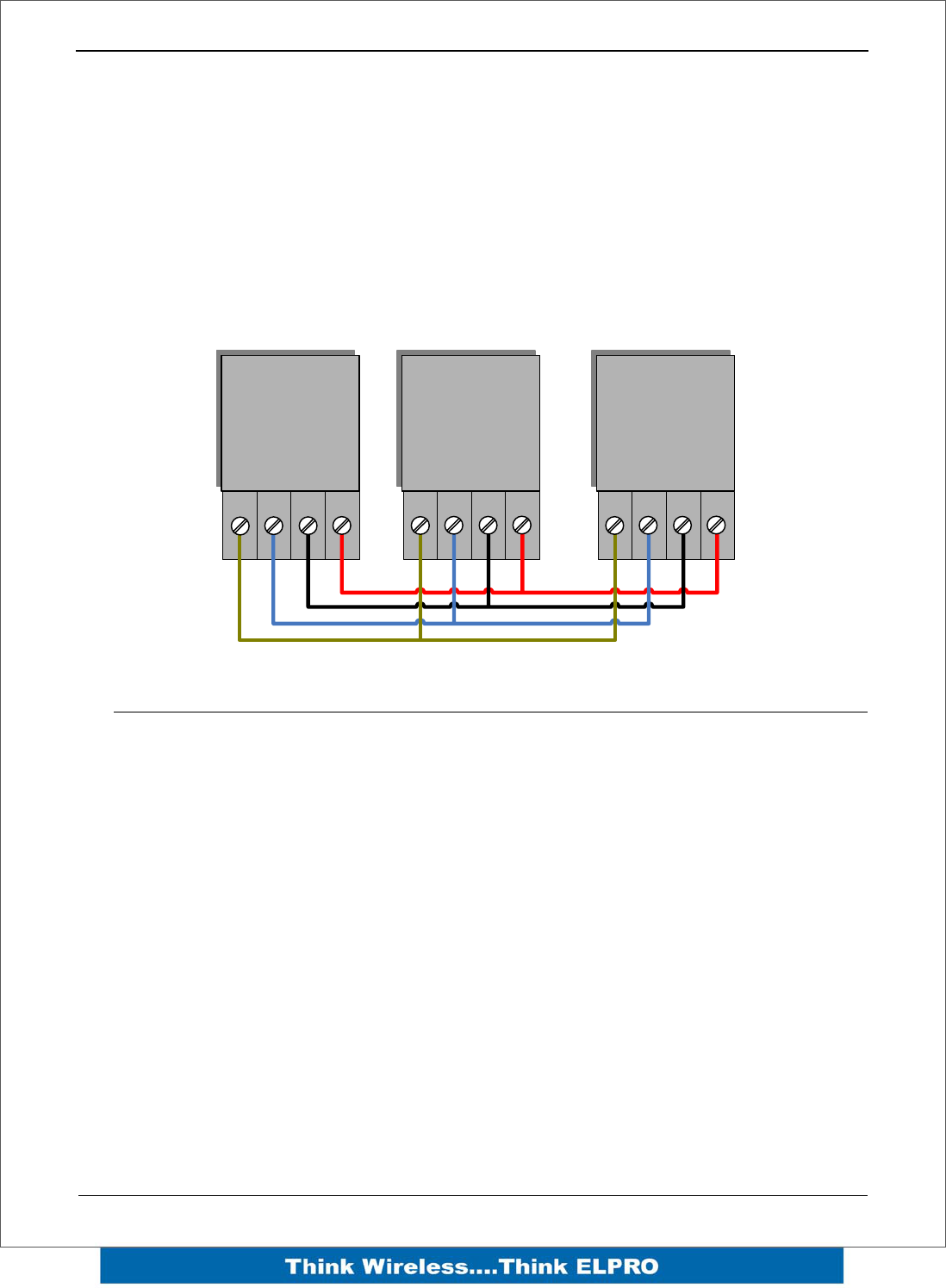
D1 D2 D3 D4 D5 D6 D7 D8 AI 1 AI2 AI3 AI4 AO1 AO2
COM+24V+-+- COM+24V++
D1 D2 D3 D4 D5 D6 D7 D8 AI 1 AI2 AI3 AI4 AO1 AO2
COM+24V+-+- COM+24V++

E2 Wireless I/O Page 43
RS232 / RS485 Serial Port Configuration
RS232 Port Select the desired functionality. Select either Serial Gateway
or Modbus TCP to RTU
Data Rate The serial data rate desired. Serial data rates available range
from 110bps to a maximum of 230,400bps.
Data Format The data format desired. All the standard data formats are
supported.
Flow Control Selects CTS/RTS or None
RS232 / RS485 Modbus TCP / RTU Converter
Pauses Between
Requests Enter the delay between serial request retries in milliseconds
Response Timeout
Enter the serial response timeout in milliseconds – a serial
retry will be sent if a response is not received within this
timeout.
Connection Timeout
Enter the TCP connection timeout in seconds – if no
Modbus/TCP data is received within this timeout then the TCP
connection will be dropped. Set this field to zero for no
timeout.
Maximum Request
Retries
Enter the maximum number of request retries performed
serially.
Maximum
Connections
Enter the maximum number of simultaneous TCP connections
to the server allowed.
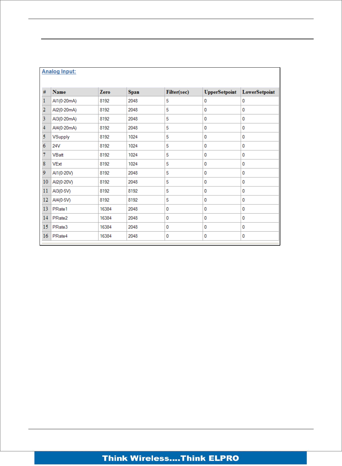
Page 44 E2 Wireless I/O
4.7 I/O Configuration
Analog Inputs
The following configuration parameters are available on the E2 Analog inputs
Name – Can re-name the inputs or use the default, up to 30 characters including
spaces.
Zero / Span – These variables will change the Scale of the Analog Inputs.
Filter (sec) – The Filter time is the time for the analog to reach 63% of its settled value
on a step change. By default the Pulsed inputs are not filtered.
Setpoints – All of the analogs have an Upper and a Lower setpoint, which can be used
as an indicator locally or remotely. The internal setpoint status must be mapped to an
output for this option to have effect.
The setpoints operate with a deadband or a windowed function depending on what
values are entered in each setpoint location. Setpoint values are in whatever the raw
input is , i.e. AI 1-4 will be mA, AI5-12 will be Volts and AI13-16 will be in Hertz.
• Upper setpoint: Positive indicates deadband function, Negative indicates
windowed function.
• Lower Setpoint: Positive indicates normal function, Negative indicates inverted
function.
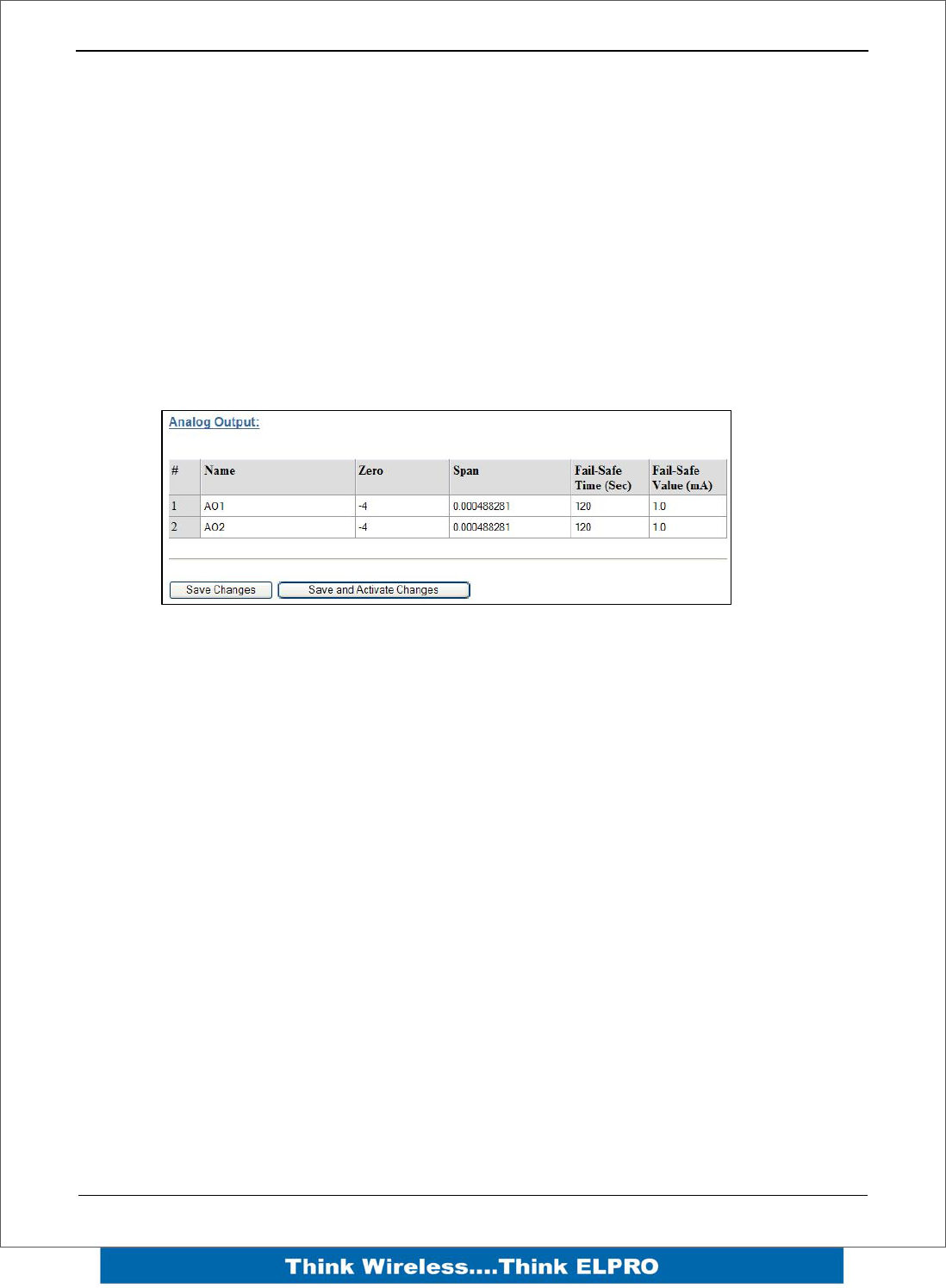
E2 Wireless I/O Page 45
Deadband - If the Analog Input is less than the Lower Set point, the set-point status will
be active (on, “1”) and remain active until the Analog Input is greater than the Upper Set
Point, the set-point status will be reset (off, “0”). Note that the Upper Set Point must
always be higher than the Lower Set Point.
Windowed –The Upper and Lower sets are used to setup a “window” within the analog
range. If the analog value is inside of this window, the setpoint will be active (on, “1”),
and if the analog value is outside of this window, the setpoint will be reset (off, “0”)
Inverted - If the Upper and Lower setpoint values are entered as negative numbers the
inverse of the “Deadband” and “Windowed” will occur, i.e. The function is exactly the
same however the setpoint logic will be inverted. (If setpoint was on, inverted will be off)
Analog Outputs
Name – Can re-name the outputs or use the default, up to 30 characters including
spaces.
Zero / Span – These variables will change the Scale of the Analog Outputs.
Failsafe Time (sec) – The Fail Safe Time is the time the output needs to count down
before activating the failsafe state. Receiving an update or a COS message will reset
the Fail Safe Timer back to its starting value. If the Fail Safe Timer gets down to zero
then the output will be set to the Fail Safe state (mA)
It is recommend this Fail Safe Time be configured for a little more than twice the update
time of the input that is mapped to it, that way the output will reset if it fails to receive
two update messages.
Failsafe Time (sec) – The value that you wish the output the reset to.
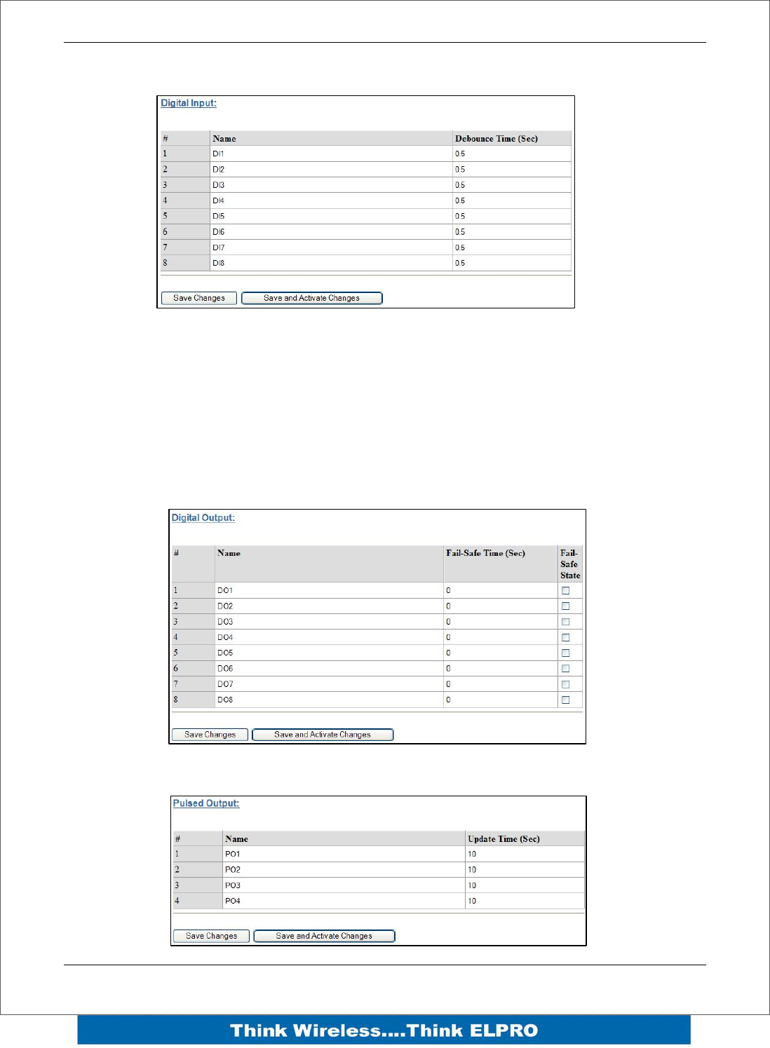
Page 46 E2 Wireless I/O
Digital Input
Name – Can re-name the inputs or use the default, up to 30 characters including
spaces.
Debounce Time (sec) – Debounce is the time which an input must stay stable before
the module decides that a change of state has occurred. If a digital input changes (on -
off) and changes again (off - on) in less than the debounce time, then the module will
ignore both changes. Default debounce time is .5 seconds.
Digital Output
Pulsed Inputs

E2 Wireless I/O Page 47
4.8 Module Information
This configuration page is primarily for information purposes. With the exception of the
password, the information entered here is displayed on the home configuration
webpage of the E2.
Username Configuration of Username. This is the username used to
access the configuration on the E2. Take care to remember
this username if you change it as it will be needed to access
the E2 in future.
Password
Configuration of Password. This is the password used to
access the configuration on the E2. Take care to remember
this password if you change it as it will be needed to access
the module in future.
Device Name A text field if you wish to label the particular E2.
Owner A text field for owner name.
Contact A text field for owner phone number, email address etc.
Description A text field used for a description of the purpose of the unit.
Location A text field used to describe the location of the E2.
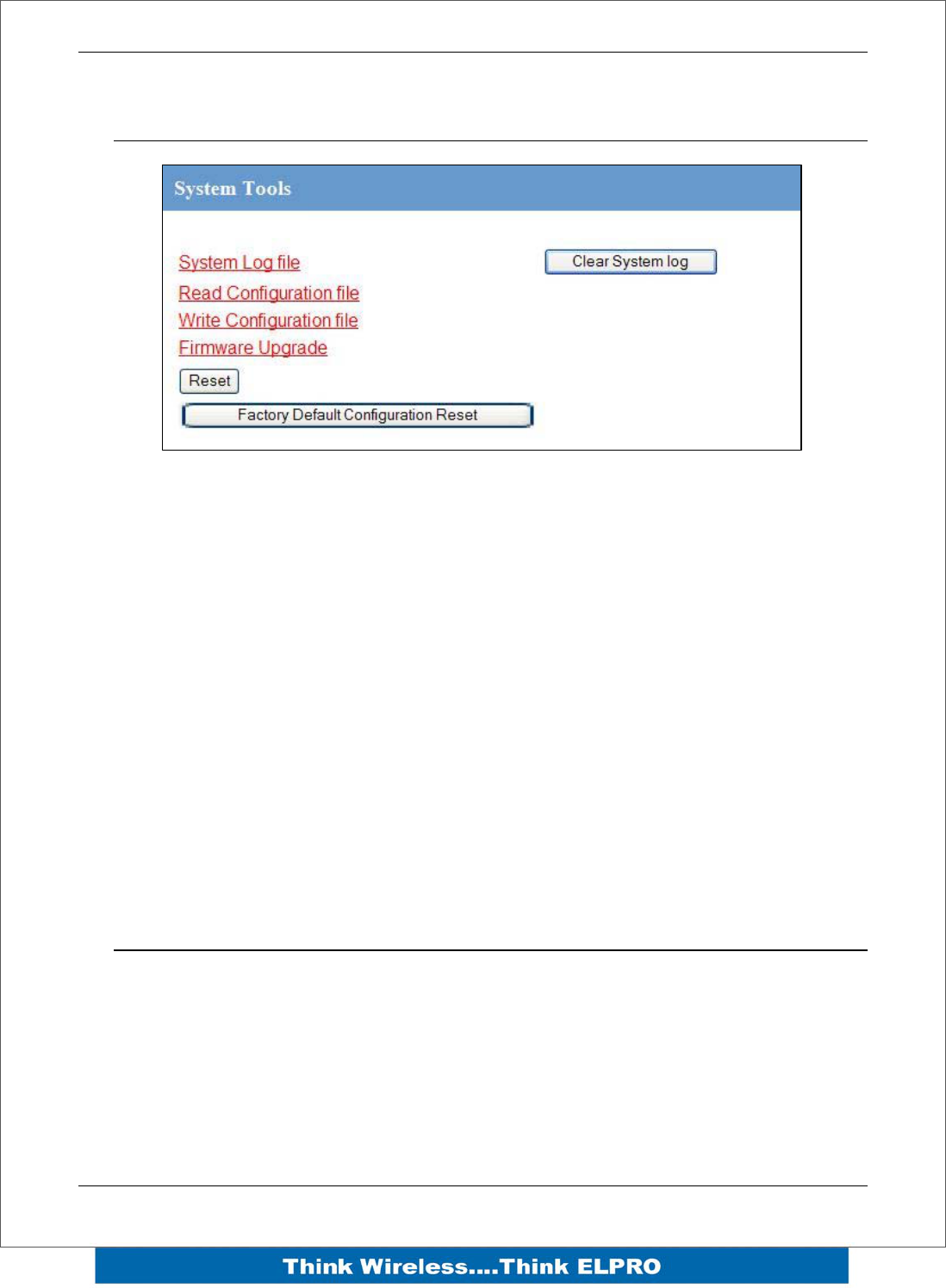
Page 48 E2 Wireless I/O
4.9 System Tools
This screen is where you can log system instructions, etc to the screen and from there
you can save to a file.
This screen also is where any uploading and saving of the configuration is done.
Reading Configuration File
Reads the module configuration into an XML file for saving.
Writing Configuration File
Allows you to load an XML configuration file into the module and then reset
Firmware Upgrade
This option allows the module firmware to be updated by loading a special firmware file
into the module and then performing a reset. The module will then go through a boot
routine and loads the new firmware.
4.10 Address Map
The I/O data store provides storage of all I/O data in the system. The data store
provides services to other processes, and is configured indirectly by the other
processes making use of it’s services.
The I/O Store provides eight different “data files”. Two bit files, two word files, two long-
word files and two floating point files. The two files of each type in turn support inputs
and outputs on the local machine, and data storage for the gateway function of the
machine.
E2 Wireless I/O Page 49
These files are mapped into the address map as described below.
Store name Type Size Address
dot discrete outputs 3000 (bits) 00001
din discrete inputs 2500 (bits) 10001
ain word inputs (16-bit) 2500 (words) 30001
aot word outputs(16-bit) 2500 (words) 40001
pin long inputs (32-bit) 20 (longwords) 36001
real_ain float inputs (32-bit) 20 (floats) 38001
pot long outputs (32-bit) 20 (longwords) 46001
real_aot float outputs (32-bit) 20 (floats) 48001
The E2 provides an address map, which maps the internal register files to addresses.
Addresses are common for ELPRO protocol and for Modbus Protocol. The table also
details the internal IO Store name for each of the address ranges.
The following table shows the basic onboard I/O available in a standard E2 module with
no expansion I/O connected. For a more detailed I/O map (showing the full register
range), see Appendix A at the end of the manual.
Standard E2 I/O (Basic Local I/O with no expansion modules)
Address Input / Output Description
0001
0008 Local DIO1 – DIO8 (as Outputs)
10001
10008 Local DIO1 – DIO8 (as inputs)
10009
10020
Setpoint status from Analog inputs 1 through 12. (AI1,2,3,4 Current
Mode), (Internal Supplies), (AI1,2,3,4 Voltage Mode)
30001
30004
Local AI1 – AI4. (Current Mode)
( AI1, AI2 4-20mA diff., AI3, AI4 4-20mA Sink)
30005
30006
30007
30008
Local Supply voltage (8-40V scaling)
Local Battery voltage
Local 24V loop voltage
115S Supply Voltage

Page 50 E2 Wireless I/O
30009
30012
Local AI1 – AI4. (Voltage Mode)
( AI1, AI2 0-10V, AI3, AI4 0-5V)
30013
30016 Local Pulse rate inputs PI1 – PI4
40001
40002
Local AO1 – AO2
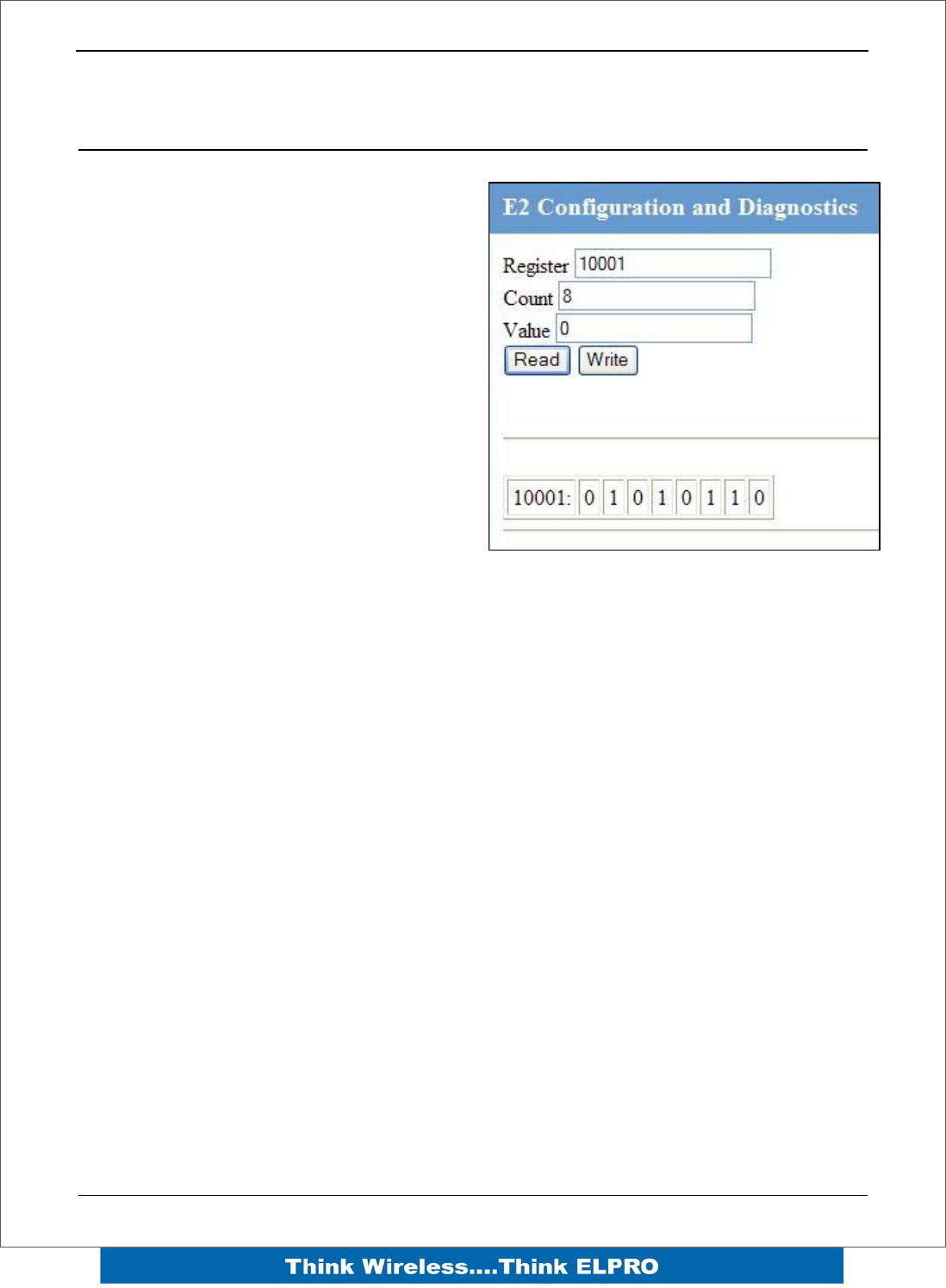
E2 Wireless I/O Page 51
Chapter 5 – Diagnostics
5.1 IO Diagnostics
By selecting this option on the main screen
will allow some basic reading and writing of
the I/O store within the module.
To read a location, enter an address
location, e.g. 10001 (for digital Inputs),
enter a count (number of consecutive
registers) and then press the “Read” button
Below the buttons, you will see the returned
address location and values
To Write to outputs , enter the address
location, count and value and then press
the “Write” button.
You will then see the outputs change to the
value you entered.
E.g. Write to Register 1 with a count of 8 and a value of 65535 will turn all the Local
Digital Outputs on.
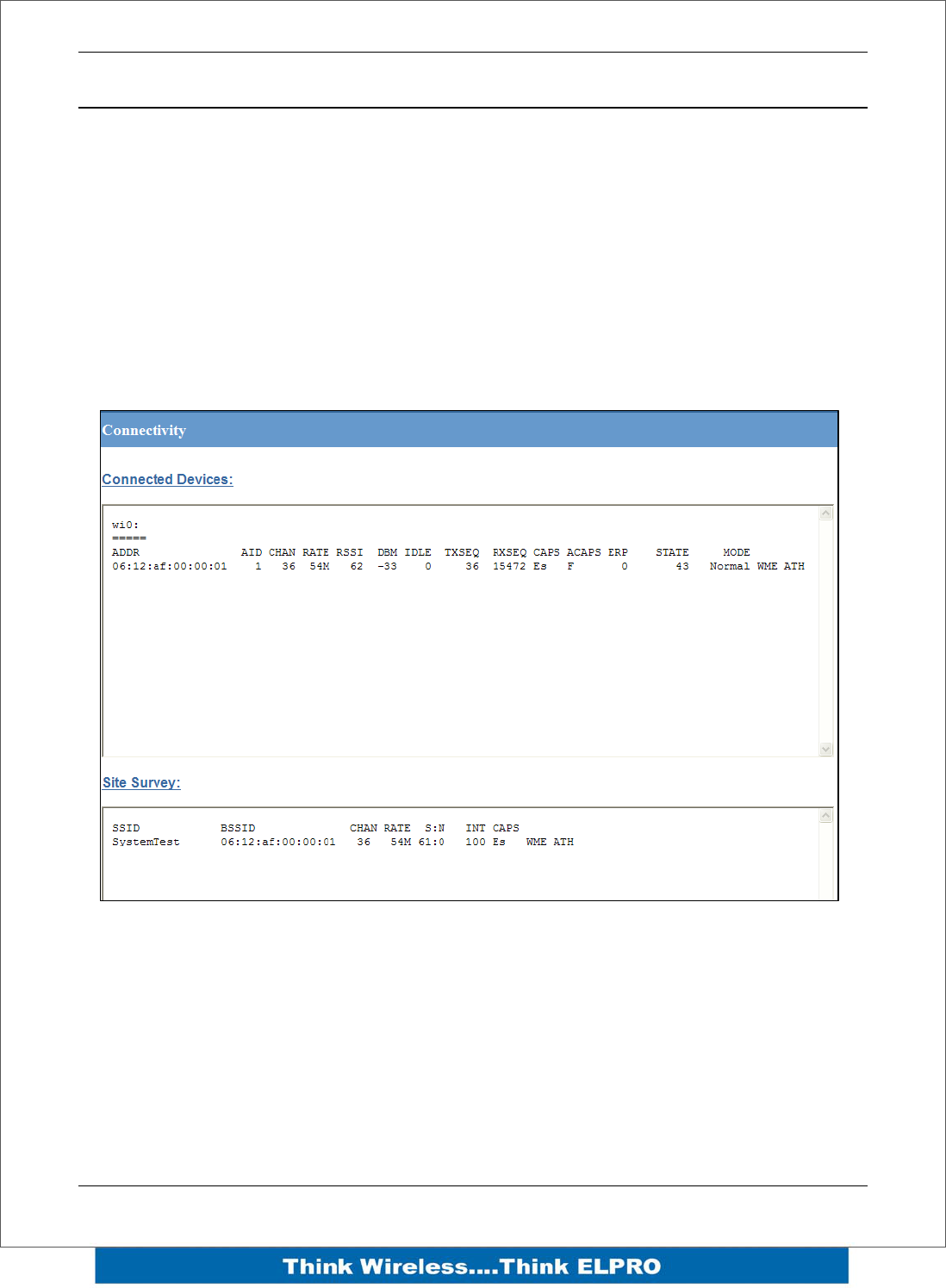
Page 52 E2 Wireless I/O
5.2 Diagnostic Information
Connectivity
The Connectivity webpage displays connections and available networks. The
“Connected Devices” section displays the radio channel, received signal strength, and
radio data rate for each Client or Access Point by their MAC Address. The readings
shown are based upon the last received data message from the Access Point or Client.
Client stations also display a list of detected Access points (Site Survey), including
network name (SSID), channel and maximum data rate.
Note that when updating the Connectivity webpage, it is necessary to hold down the
<ctrl> key while pressing the refresh button. Otherwise, the information will not be
updated.
Statistics
The Statistics webpage is used for advanced debugging of E2. This webpage details
the state of the E2 and performance information. This page is typically useful to ELPRO
technical support personnel in diagnosing problems with the module.
Note that when updating the Statistics webpage, it is necessary to hold down the <ctrl>
key while pressing the refresh button. Otherwise, the information will not be updated.
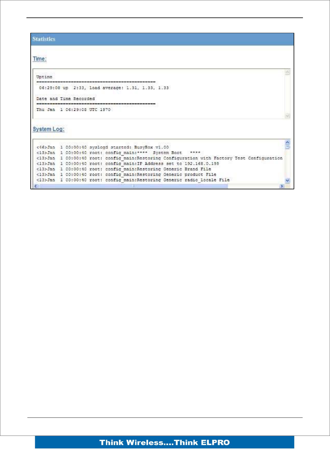
E2 Wireless I/O Page 53

Page 54 E2 Wireless I/O
5Appendix A
6Appendix A I/O Store
“Output Coils”
0001
0008 Local DIO1 – DIO8 (as Outputs) at address 1-8.
0009
0020 Spare
0021
0040
Locally attached 115s modules DIO Outputs
(See 115S detail below)
0041
0500 (space for up to 24 115S modules – 20 registers)
0501
3000
General Purpose Bit Storage – Used for:
• Staging area for data concentrator
• Fieldbus Mappings storage
• Force Mapping registers (assigned in Config)
3001
10000 Not Available
“Input Bits”
10001
10008
Local DIO1 – DIO8 (as inputs) at address 1-8.
(115S-11 DIO1-DIO16)
10009
10020 SetPoint status from Analog inputs 1 through 12.
10021
10040
Locally attached 115s modules DIO Inputs
(See 115S detail below)
10041
10500
(space for up to 24 115S modules)
10501
10595 Comm Fail Status to remote with address (location -10500)
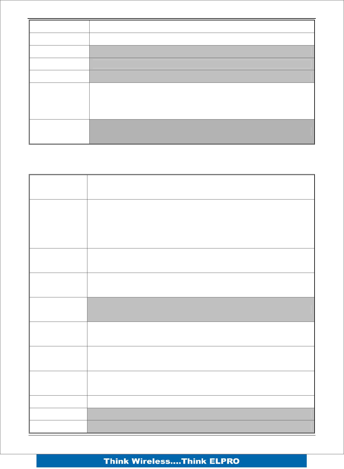
E2 Wireless I/O Page 55
10596 Message Buffers Exhausted Alarm
10597 Message Buffers Exhausted Alarm Latch
10598 Spare
10599 Spare
10600 Spare
10601
12500
General Purpose Bit Storage – Used for:
• Staging area for data concentrator
• Fieldbus Mappings storage
12501
30000 Not Available
“Input Registers”
30001
30004
Local AI1 – AI4. (Current Mode)
( AI1, AI2 4-20mA diff., AI3, AI4 4-20mA Sink)
30005
30006
30007
30008
Local Supply voltage (8-40V scaling)
Local Battery voltage
Local 24V loop voltage
115S Supply Voltage
30009
30012
Local AI1 – AI4. (Voltage Mode)
( AI1, AI2 0-10V, AI3, AI4 0-5V)
30013
30016 Local Pulse rate inputs PI1 – PI4
30018
30020 Spare
30021
30040
Locally attached 115smodules
(See 115S detail below)
30041
30500
(space for up to 24 115S modules)
30501
30595 RSSI Level from Neighbour with address (location -30500)
30596 Message Buffer Exhausted Counter
30597 Spare
30598 Spare
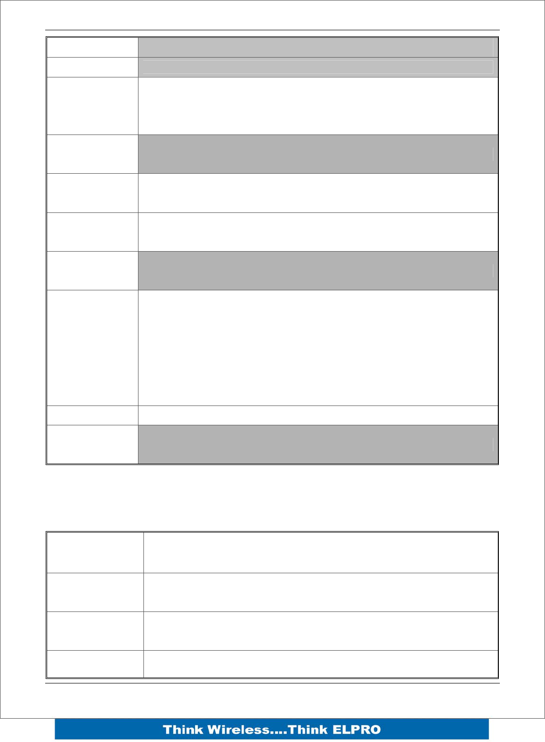
Page 56 E2 Wireless I/O
30599 Spare
30600 Spare
30601
32500
General Purpose word Storage – Used for:
• Staging area for data concentrator
• Fieldbus Mappings storage
32501
36000 Not Available
36001
36008
Local Pulsed inputs 1-4.B.E Format.
Most significant word at lower / odd address.
36009
36040 spare
36041
38000 Not Available
38001
38032
Local Analog inputs as floating point values
Modscan Format (Sign + Exponent + Most significant 7 bits of
significant at Even / Higher Addressed location. Lower 16 bits of
Significant at lower / Odd addressed location)
(12.3 => 38001=CCCD, 38002=4144)
38033 - 38040 Spare space for floating point values
32501
40000 Not Available
“Holding Registers”
40001
40002
Local AO1 – AO2
40003
40020 Spare
40021
40040
Locally attached 115smodules
(See 115S detail below)
40041
(space for up to 24 115S modules)

E2 Wireless I/O Page 57
40500
40501
42500
General Purpose word Storage – Used for:
• Staging area for data concentrator
Fieldbus Mappings storage
42501
46000 Not Available
46001
46008
Local Pulsed Outputs 1-4. B.E Format. Most significant word at
lower / odd address.
46009
46040 spare
36041
38000 Not Available
48001
48004
Local Analog outputs as floating point values
Modscan Format (Sign + Exponent + Most significant 7 bits of
significant at Even / Higher Addressed location. Lower 16 bits of
Significant at lower / Odd addressed location)
(12.3 => 48001=CCCD, 48002=4144)
40005
48040 Spare space for floating point values
48041
onwards Not Available