ELPRO Technologies ELP905K Spread Spectrum Radio Modem User Manual man FCC 905K 1 0
ELPRO Technologies Pty Ltd Spread Spectrum Radio Modem man FCC 905K 1 0
UserManual.wiki
>
ELPRO Technologies
>
ELP905K User Manual
>
User manual
Contents
1.
User manual
2.
Professional installation details
3.
Yagi antenna with CC20 900 cable
4.
RF exposure information
5.
Ammended user manual re professional installation
User manual
Navigation menu
Upload a User Manual
Namespaces
Wiki Guide
HTML
PDF
Info
Views
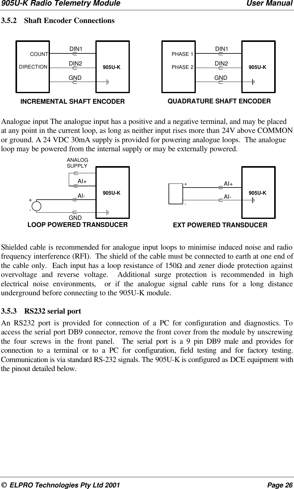
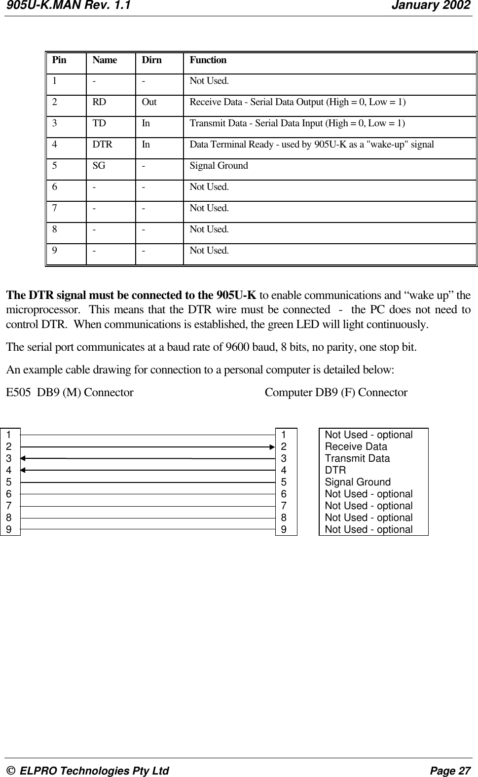
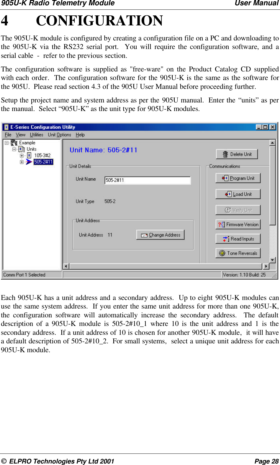
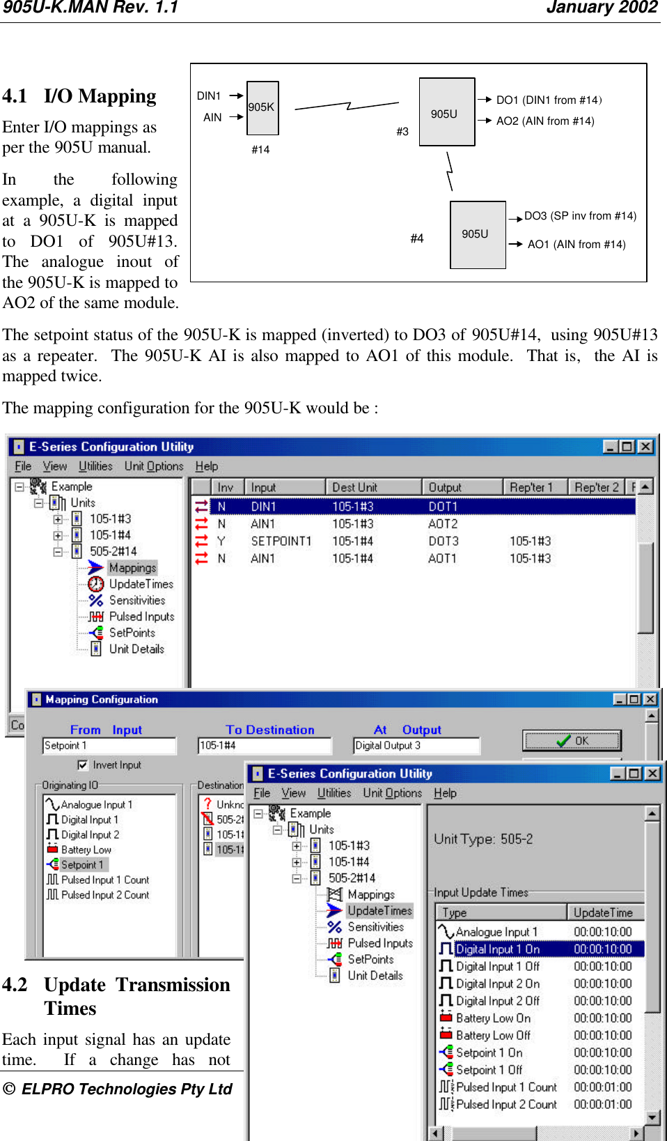
User Manual
Discussion / Help
Navigation