ELPRO Technologies ELPSS0D Frequency hopping spreadspectrum transmitter User Manual Man 905UD 2 0
ELPRO Technologies Pty Ltd Frequency hopping spreadspectrum transmitter Man 905UD 2 0
Contents
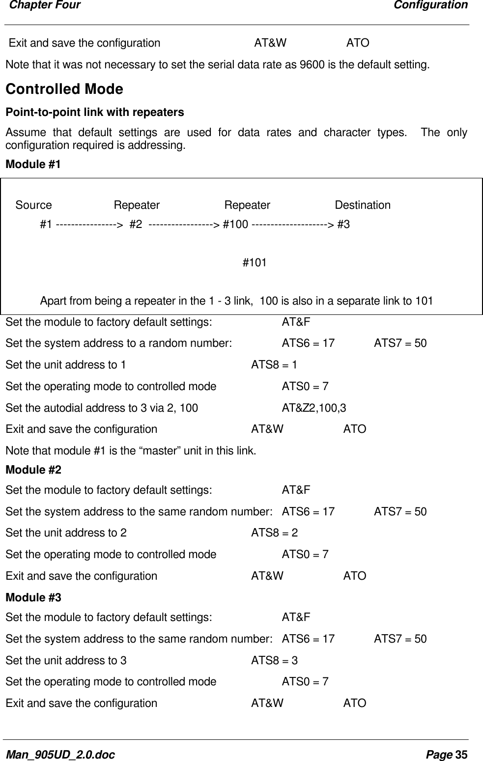
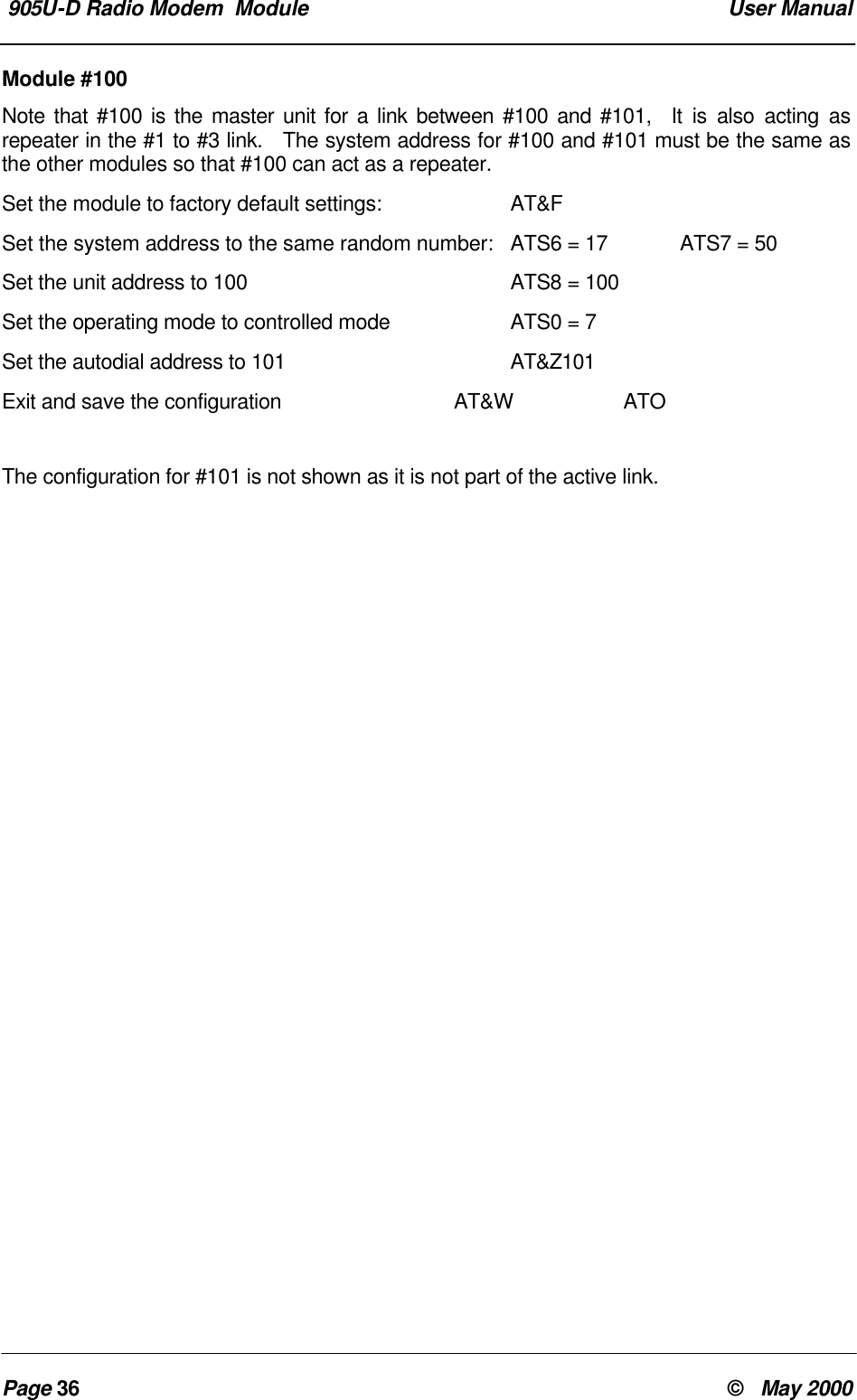
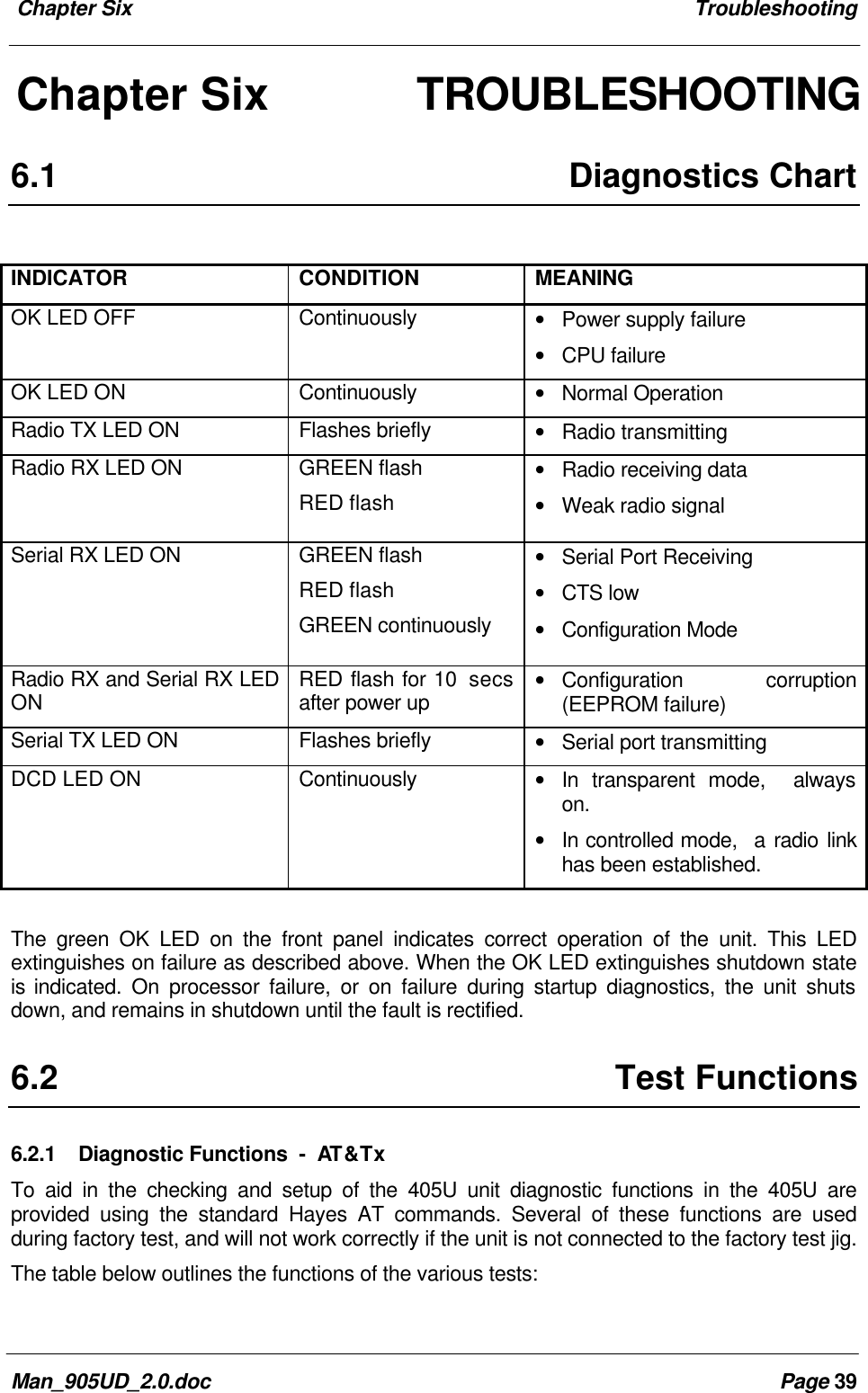
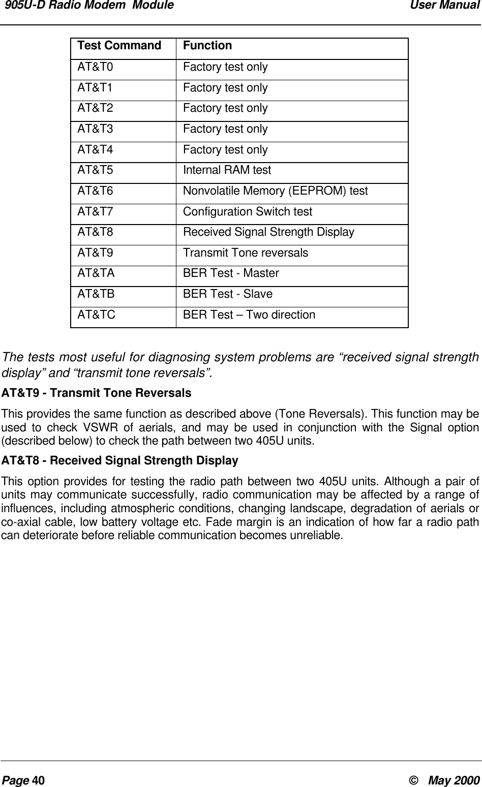
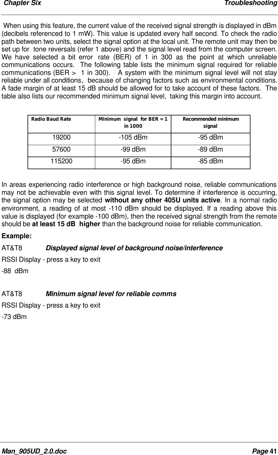
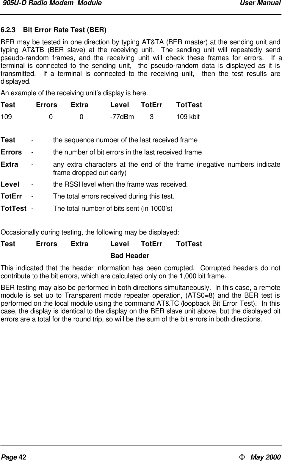
- 1. Users manual
- 2. Revised user manul
- 3. Revised User Manual
Revised user manul