ELPRO Technologies ELPSS0D Frequency hopping spreadspectrum transmitter User Manual man 905ud 2 0
ELPRO Technologies Pty Ltd Frequency hopping spreadspectrum transmitter man 905ud 2 0
Contents
- 1. Users manual
- 2. Revised user manul
- 3. Revised User Manual
Users manual

905U-D Radio Modem Module User Manual
Page 2© May 2000
Thank you for your selection of the 905U-D radio modem. We trust it
will give you many years of valuable service.
ATTENTION!
Incorrect termination of supply wires may
cause internal damage and will void warranty.
To ensure your 905U-D enjoys a long life,
double check ALL your connections with
the user’s manual
before turning the power on.

Contents
Man_905UD_2.0.doc Page 3
FCC Notice:
This user’s manual is for the ELPRO 905U-D radio modem. This device complies with Part
15.247 of the FCC Rules.
Operation is subject to the following two conditions:
1) This device may not cause harmful interference and
2) This device must accept any interference received, including interference that may
cause undesired operation.
This device must be operated as supplied by ELPRO Technologies Pty Ltd. Any changes or
modifications made to the device without the written consent of ELPRO Technologies Pty.
Ltd. May void the user’s authority to operate the device.
End user products that have this device embedded must be supplied with non-standard
antenna connectors, and antennas available from vendors specified by ELPRO
Technologies. Please contact ELPRO Technologies for end user antenna and connector
recommendations.
Notices:
Safety:
Exposure to RF energy is an important safety consideration. The FCC has adopted a safety
standard for human exposure to radio frequency electromagnetic energy emitted by FCC
regulated equipment as a result of its actions in General Docket 79-144 on March 13, 1996.
CAUTION:
To comply with FCC RF Exposure requirements in section 1.1310 of the FCC Rules,
antennas used with this device must be installed to provide a separation distance of at least
20 cm from all persons to satisfy RF exposure compliance.
DO NOT:
• operate the transmitter when someone is within 20 cm of the antenna
• operate the transmitter unless all RF connectors are secure and any open connectors
are properly terminated.
• operate the equipment near electical blasting caps or in an explosive atmosphere
All equipment must be properly grounded for safe operations. All equipment should be
serviced only by a qualified technician.

905U-D Radio Modem Module User Manual
Page 4© May 2000
How to Use This Manual
To receive the maximum benefit from your 905U-D product,
please read the Introduction, Installation and Operation
chapters of this manual thoroughly before putting the 905U-D to
work.
Chapter Four Configuration details the configurations available
and explains the diverse operation of the product in detail.
Chapter Five Specifications details the features of the product
and lists the standards to which the product is approved.
Chapter Six Troubleshooting will help if your system has
problems and Chapter Seven specifies the Warranty and
Service conditions.
The foldout sheet 905U-D Installation Guide is an installation
drawing appropriate for most applications.

Contents
Man_905UD_2.0.doc Page 5
WARNING
1. In some countries, a radio licence is not required for the 905U-D telemetry modules
provided the module is installed using the aerial and equipment configuration
described in the 905U-D Installation Guide. In other countries, refer to the relevant
Regulatory Authority. Check the Installation Guide for your country listing.
2. Where a radio licence is not required, operation is authorised by the relevant
Authority in your country on a non-protection basis. Although all care is taken in the
design of these units, there is no responsibility taken for sources of external
interference. Some delay in the operation of the module may occur during periods of
interference. Systems should be designed to be tolerant of these delays.
3. To avoid the risk of electrocution, the aerial, aerial cable, and all terminals of the
905U-D module should be electrically protected. To provide maximum surge and
lightning protection, the module should be connected to a suitable earth and the
aerial, aerial cable, and the module should be installed as recommended in the
Installation Guide.
4. To avoid accidents during maintenance or adjustment of remotely controlled
equipment, all equipment should be first disconnected from the 905U-D module
during these adjustments. Equipment should carry clear markings to indicate remote
or automatic operation. eg. "This equipment is remotely controlled and may start
without warning. Isolate at the switchboard before attempting adjustments."
5. The 905U-D module is not suitable for use in explosive environments without
additional protection.

905U-D Radio Modem Module User Manual
Page 6© May 2000
CONTENTS
CHAPTER ONE INTRODUCTION..........................................................................................8
1.1 GENERAL .........................................................................................................................8
1.2 TRANSPARENT MODE .......................................................................................................9
1.3 CONTROLLED MODE ......................................................................................................10
1.4 REPEATER UNITS ...........................................................................................................11
CHAPTER TWO INSTALLATION..........................................................................................12
2.1 GENERAL .......................................................................................................................12
2.2 AERIAL INSTALLATION .....................................................................................................12
2.2.1 Dipole aerial......................................................................................................13
2.2.2 Three element Yagi aerial.................................................................................13
2.2.3 Collinear (3dB) aerial........................................................................................14
2.3 POWER SUPPLY.............................................................................................................15
2.4 SERIAL CONNECTIONS ...................................................................................................15
2.4.1 RS232 Serial Port.............................................................................................15
2.4.2 RS485 Serial Port.............................................................................................16
2.5 COMMUNICATIONS OK (DCD) OUTPUT..........................................................................17
CHAPTER THREE OPERATION ..........................................................................................18
3.1 POWER-UP AND NORMAL OPERATION .............................................................................18
3.2 SERIAL AND RADIO DATA ................................................................................................19
3.2.1 Character Type.................................................................................................19
3.2.2 Serial Data Rate...............................................................................................19
3.2.3 Radio Data Rate...............................................................................................20
3.3 TRANSPARENT MODE .....................................................................................................21
3.4 CONTROLLED MODE ......................................................................................................21
3.5 WHAT OPERATING MODE TO USE ?.................................................................................25
3.6 OPERATING PROBLEMS ..................................................................................................26
CHAPTER FOUR CONFIGURATION...................................................................................28
4.1 BEFORE CONFIGURING ..................................................................................................28
4.2 CONFIGURATION MODE ..................................................................................................28
4.3 HAYES COMMANDS .........................................................................................................28
4.3.1 Unit Reset.........................................................................................................29
4.3.2 Storing Configuration Parameters - Write Registers.......................................29
4.3.3 Default Values - Restore Factory Defaults ......................................................29
4.3.4 S-Registers ......................................................................................................29
4.3.5 Changing Destination/Repeater Address - autodial.......................................33
4.3.6 Connecting to a Remote Module – single dial.................................................34
4.3.7 Reading Configuration Parameters..................................................................34
4.3.8 Unit Test commands - AT&Tx........................................................................34

Contents
Man_905UD_2.0.doc Page 7
4.3.9 Version Information - ATI...............................................................................34
4.3.10 Character Type - AT&Bx.................................................................................35
4.3.11 Character Type - AT&Mx.................................................................................35
4.3.12 Verbose mode control, Local Echo control, and Quiet mode..........................35
4.3.13 Responses .......................................................................................................35
4.4 CONFIGURATION EXAMPLES............................................................................................36
CHAPTER FIVE SPECIFICATIONS ......................................................................................39
CHAPTER SIX TROUBLESHOOTING.................................................................................41
6.1 DIAGNOSTICS CHART .....................................................................................................41
6.2 TEST FUNCTIONS...........................................................................................................41
6.2.1 Radio Testing using Tone Reversals...............................................................41
6.2.2 Diagnostic Functions - AT&Tx .......................................................................42
6.2.3 Bit Error Rate Test (BER)................................................................................44
CHAPTER SEVEN WARRANTY & SERVICE.......................................................................45
APPENDIX A SWITCH CONFIGURATION..........................................................................46
1.0 INTRODUCTION...............................................................................................................46
1.0.1 Default Configuration........................................................................................47
1.0.2 Transparent Mode ............................................................................................47
1.0.3 Controlled Mode................................................................................................47
1.1 CONFIGURATION PARAMETERS .......................................................................................51
1.1.1 Operating Mode................................................................................................52
1.1.2 Tail Time...........................................................................................................52
1.1.3 Message Length...............................................................................................52
1.1.4 Serial Data Rate...............................................................................................53
1.1.5 Radio Data Rate...............................................................................................53
1.1.6 Transmit Hold-off Time.....................................................................................53
1.1.7 Receive Hold-off Time......................................................................................54
1.1.8 Character Type.................................................................................................54
1.1.9 Connect Update Time......................................................................................55
1.1.10 Reset to Factory Default Settings ....................................................................55
1.2 CONFIGURATION EXAMPLE..............................................................................................55
APPENDIX B DECIMAL TO BINARY TABLE.......................................................................58
905U-D Radio Modem Module User Manual
Page 8© May 2000
Chapter One INTRODUCTION
1.1 General
The 905U-D radio modem module has been designed to provide flexible and reliable radio
modem functions, at an economical price. Radio modems transmit serial data over a long
distance via radio. The serial data is not changed - the output data is the same as the input
data. Although the 905U-D is intended to be simple in its application, it also provides many
sophisticated features. This manual should be read carefully to ensure that the modules are
configured and installed to give reliable performance.
Each 905U-D module will connect to a host device by RS232 or RS485 serial connection.
Examples of host devices are PLC’s, data loggers, intelligent transducers and computers.
The 905U-D unit can receive data from the host device and transmit this data by radio to
another (or several) 905U-D module. The other module will recreate the serial data and
output it as either a RS232 or RS485 serial signal. The 905U-D unit provides two-way
communications - each module can accept serial data and also output serial data.
The 905U-D module includes power supply, microprocessor controller, serial input/output
circuits and a UHF radio transceiver - no external electronics are required. The 905U-D radio
frequency has been selected to meet the requirements of unlicensed operation for remote
monitoring and control of equipment. That is, a radio licence is not required for the 905U-D
modules in many countries. See Chapter Five Specifications for details. The units are
configured from a terminal using Hayes commands or by using switches under the plastic
cover on the front of the unit.
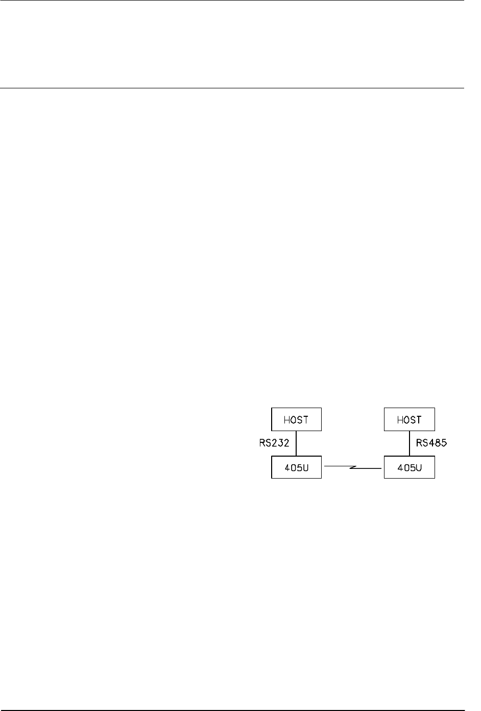
RS232 is an electrical standard format for a full duplex point-to-point serial connection.
RS485 is an electrical standard format for a
half-duplex multidrop serial connection. Up
to 32 devices can communicate on a
common RS485 serial bus. Each 905U-D
unit can only connect to one serial signal -
either RS232 or RS485. However different
modules in the same system can connect
to different types of serial signals. For
example, RS232 data from one host device
can be transmitted to a remote 905U-D unit
and output as RS485 data to another host device.
The 905U-D has been designed to be flexible enough to cover a wide range of applications.
The user is able to configure many different parameters such that the 905U-D unit will
connect reliably to different types of host devices. Before the radio modem can be used,
these parameters must be configured. Some of these parameters are :-
• Character type - the 905U-D will accept a variety of 7 or 8 data bit characters
• Serial Data Rate - between 75 and 38400 bits/sec
• Radio Data Rate - between 1200 and 9600 bits/sec
• Operating mode - transparent mode or controlled mode .
The operation of the 905U-D radio modem is relatively simple. As data is received at the
serial port, the data is transmitted on the radio channel. Up to 520 bytes of data can be
Chapter One Introduction
Man_905UD_2.0.doc Page 9
transmitted in one transmission. The
radio transmission commences when the
first data byte is received, and ends when
there are no more data bytes in the input
buffer, or when the number of bytes
transmitted equals the maximum message
length (user configurable - default 520
bytes). If more than 520 bytes is input, the
905U-D unit will transmit the first 520
bytes, then the next 520 bytes, and so on
until all of the data has been transmitted.
Because the radio data rate could be less
than the input serial data rate, an input
memory buffer of 8Kbytes is provided.
The RS232 connection provides CTS
control to prevent the buffer overflowing.
There are no data flow control signals for RS485.
A radio channel cannot provide as secure a data channel as a wired connection. The 905U-
D uses a UHF radio channel with a very low level of natural or industrial noise, however there
is a chance of interference from other users of the unlicensed radio channel. We
recommend that the flow of data over the radio channel is controlled by using error detection
and “handshaking” - that is, returning an acknowledgment transmission if a data packet is
received on the radio channel without error. This function can be performed by either the
host devices or the 905U-D modules. The modules may be configured by the user to
operate in one of two modes. In transparent mode, it is assumed that the host devices
control the flow of data. In controlled mode, the 905U-D units control the flow of data.
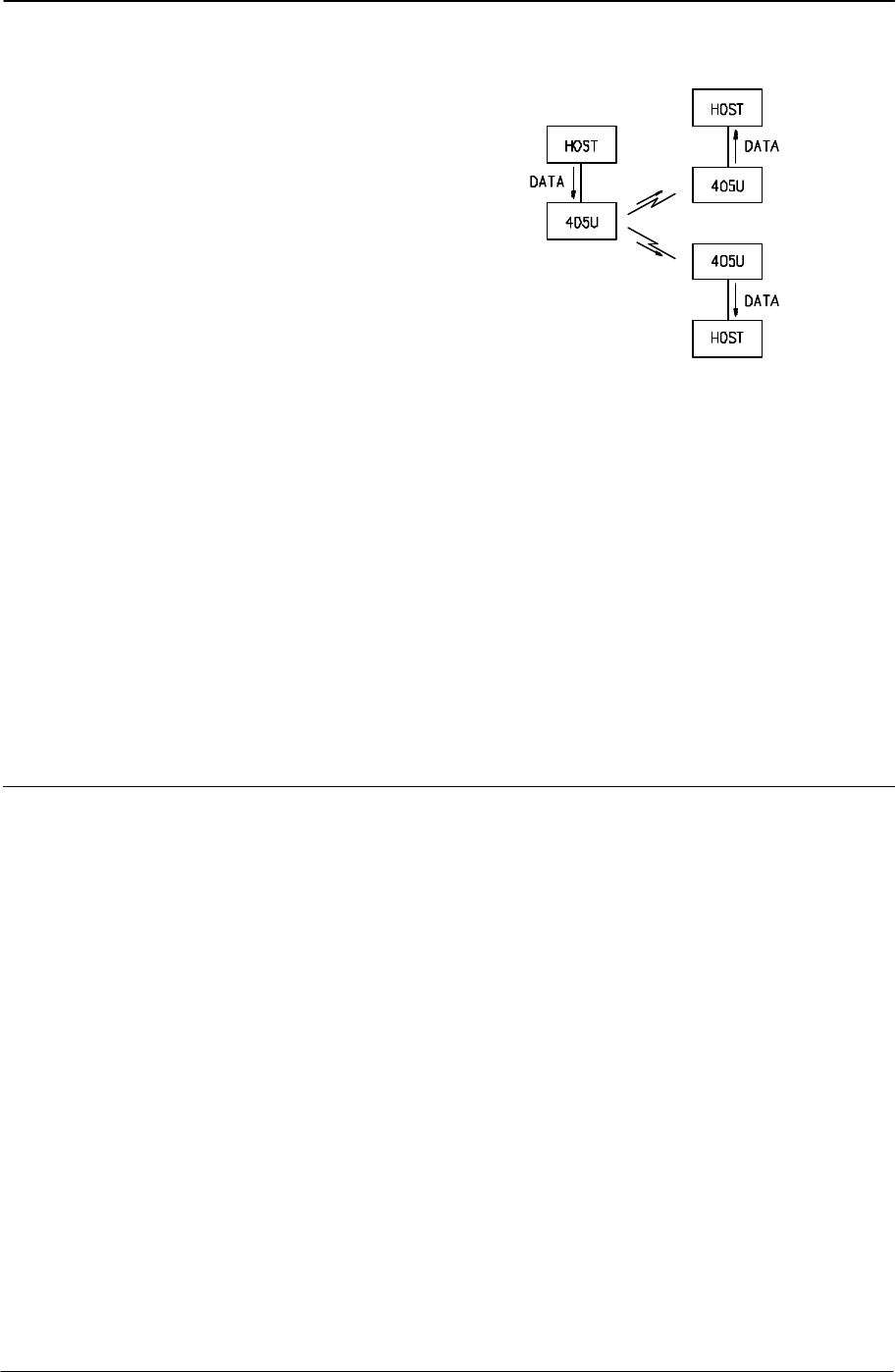
1.2 Transparent Mode
The default configuration of the 905U-D modem is transparent mode - the modules are set
in this mode at the factory. In transparent mode, there is no control of the data
transmissions. Input data is simply transmitted by radio and every other 905U-D unit in that
system which receives the transmission will output the data. This mode relies on the host
devices to perform the “handshaking” function, and re-transmitting serial data if the data is
corrupted (no “handshake”). It also relies on the host devices to include any addressing
necessary in the data. In this mode, modules are not configured with a unit address. Data
is “broadcast” - every other 905U-D in the system will receive the data and output the data
to their individual host devices. The user may configure the 905U-D modems to add error
checking to each data packet transmitted - if error checking is configured, data will not be
output if it is received without a correct error-check. This feature provides additional
protection against corruption of the data during the radio transmission. If error-checking is
not configured, then the data received by radio will be output without checking for errors.
Transparent mode is suitable for a host device which is able to communicate on a multi-drop
“bus” type network. An example of an application is the use of radio modems to extend a PLC
RS485 network. The serial messages from the PLC’s already include PLC addressing and
error detection/correction to control the flow of data.
905U-D Radio Modem Module User Manual
Page 10 © May 2000
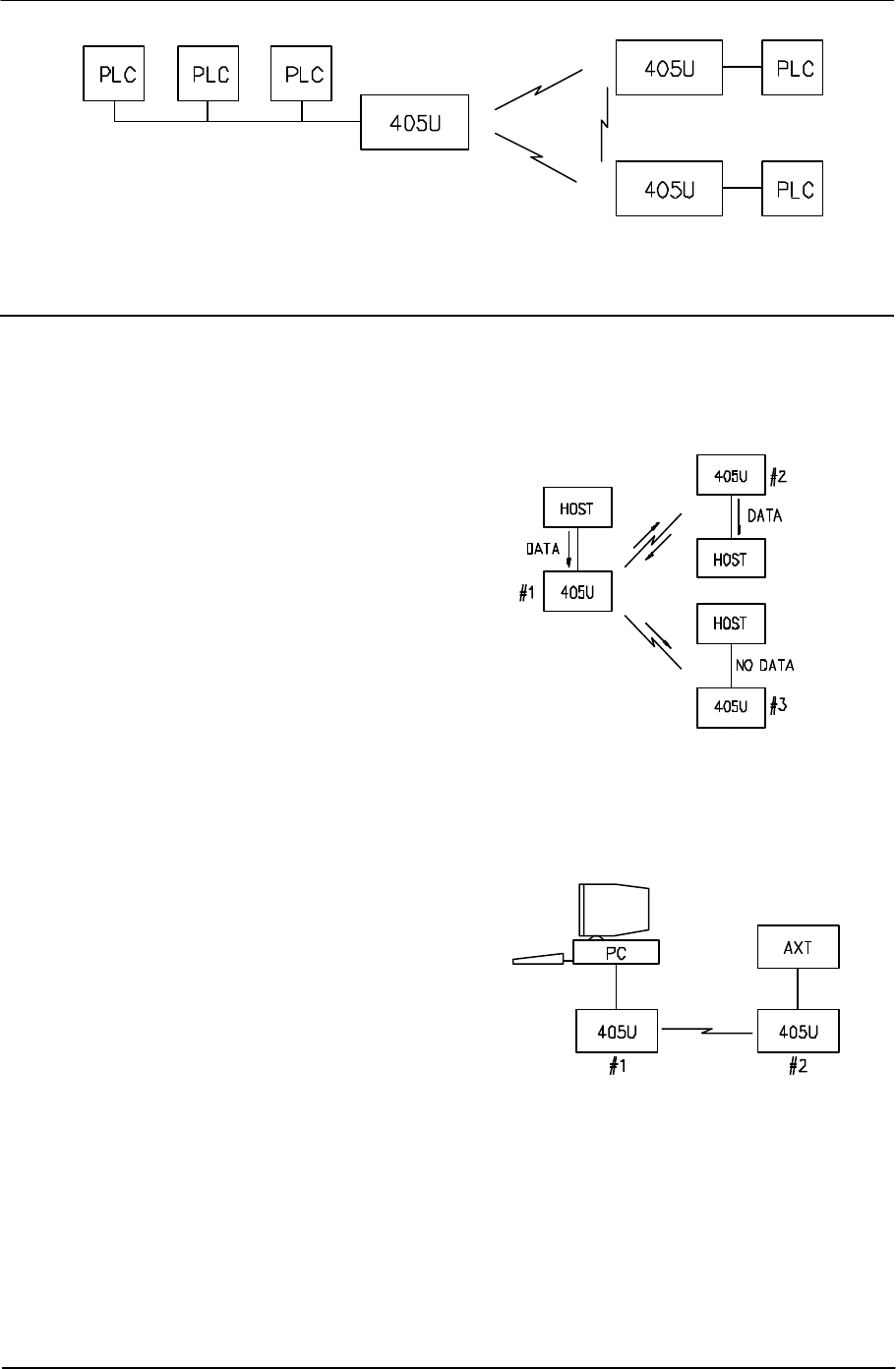
1.3 Controlled Mode
In “controlled” mode, the flow of data is controlled by the 905U-D units. Each 905U-D unit is
configured with an address by the user, and a destination address for the data to be
transmitted to. Data is transmitted addressed to the destination module, and only this
module will output the serial data. The source module will add an error-check (16 bit CRC) to
the data transmitted by radio. The
destination module will process the error-
check, and if correct, it will transmit an
acknowledgment message (ACK) back to
the source module. If the error-check is not
correct, then the destination module will
transmit a “fail” message (NACK) back to
the source module. If the source module
receives a NACK return, or does not
receive any return within 1 second, it will
re-transmit the data. The source module
will attempt to transmit the data up to five
times, until an acknowledgment (ACK) is
received. If an acknowledgment is still not received, then a “communications failure” output
will be activated, and the source module will not accept any more input data from its host
device.
An example of an application using controlled
mode would be a radio modem link between
an intelligent gas analyser and a monitoring
computer system. Intelligent transducers do
not normally provide addressing or error
checking functions - these would be provided
by the 905U-D modules.
In controlled mode, the destination address
may be set by the host device by initially
sending a “Hayes” command to the 905U-D
module, or by on-board miniature switches.
Hayes commands are a standard set of commands used with conventional telephone
modems. An example of an application that would use Hayes command to set destination
addresses would be a central computer polling data loggers for periodic information.
Chapter One Introduction
Man_905UD_2.0.doc Page 11
1.4 Repeater Units
A 905U-D unit may be used as a repeater to re-
transmit radio messages. The purpose of a
repeater unit is to extend radio range.
In transparent mode, only one module per
system may be used as a repeater. If more
than one module is configured as a repeater,
any message transmitted in the system will be
continually re-transmitted between the repeater
units. The repeater in transparent mode will
repeat every transmission it receives.
In controlled mode, up to five repeaters may be
configured for any transmission path.

905U-D Radio Modem Module User Manual
Page 12 © May 2000
Chapter Two INSTALLATION
2.1 General
The 905U-D module is housed in an rugged aluminium case, suitable for DIN-rail mounting.
Terminals will accept wires up to 2.5 sqmm in size.
Normal 110-240V mains supply should not be connected to any terminal of the 905U-D
module. Refer to Section 2.3 Power Supply.
Before installing a new system, it is preferable to bench test the complete system.
Configuration problems are easier to recognise when the system units are adjacent.
Following installation, the most common problem is poor communications caused by
incorrectly installed aerials, or radio interference on the same channel, or the radio path being
inadequate. If the radio path is a problem (ie path too long, or obstructions in the way), then
higher performance aerials or a higher mounting point for the aerial may rectify the problem.
Alternately, use an intermediate 905U-D Module as a repeater.
The foldout sheet 905U-D Installation Guide provides an installation drawing appropriate to
most applications. Further information is detailed below.
Each 905U-D module should be effectively earthed via the "GND" terminal on the 905U-D
module - this is to ensure that the surge protection circuits inside the 905U-D module are
effective.
2.2 Aerial Installation
The 905U-D module will operate reliably over large distances. The distance which may be
reliably achieved will vary with each application - depending on the type and location of
aerials, the degree of radio interference, and obstructions (such as hills or trees) to the radio
path. See the 905U-D Installation Guide for expected ranges in your country. Note that the
expected range is for radio data rates of up to 4800 bits/sec. If 9600 bit/sec rate is
configured, the transmitted data will not have the same range. The radio range for 9600
bit/sec rate will be approx 70% of the range at lower data rates.
Where it is not possible to achieve reliable communications between two 905U-D modules,
then a third 905U-D module may be used to receive the message and re-transmit it. This
module is referred to as a repeater.
An aerial must be connected to each 905U-D module using the BNC female connector at the
top of the module.
To achieve the maximum transmission distance, the aerials should be raised above
intermediate obstructions such that the radio path is true “line of sight”. Because of the
curvature of the earth, the aerials will need to be elevated at least 5 metres above ground for
paths greater than 5 km (3 miles). For short distances, the modules will operate reliably with
some obstruction of the radio path. Obstructions which are close to either aerial will have
more of a blocking effect than obstructions in the middle of the radio path. For example, a
group of trees around the aerial is a large obstruction, and the aerial should be raised above
the trees. However if there is at least 100 metres of clear path before a group of trees, the
trees will have little affect on the radio path.

Chapter Two Installation
Man_905UD_2.0.doc Page 13
An aerial should be connected to the module via 50 ohm coaxial cable (eg RG58 or RG213)
terminated with a male BNC connector. The higher the aerial is mounted, the greater the
transmission range will be, however as the length of coaxial cable increases so do cable
losses. For use on unlicensed frequency channels, there are several types of aerials
suitable for use. It is important aerials are chosen carefully to avoid contravening the
maximum power limit on the unlicensed channel - if in doubt refer to an authorised service
provider.
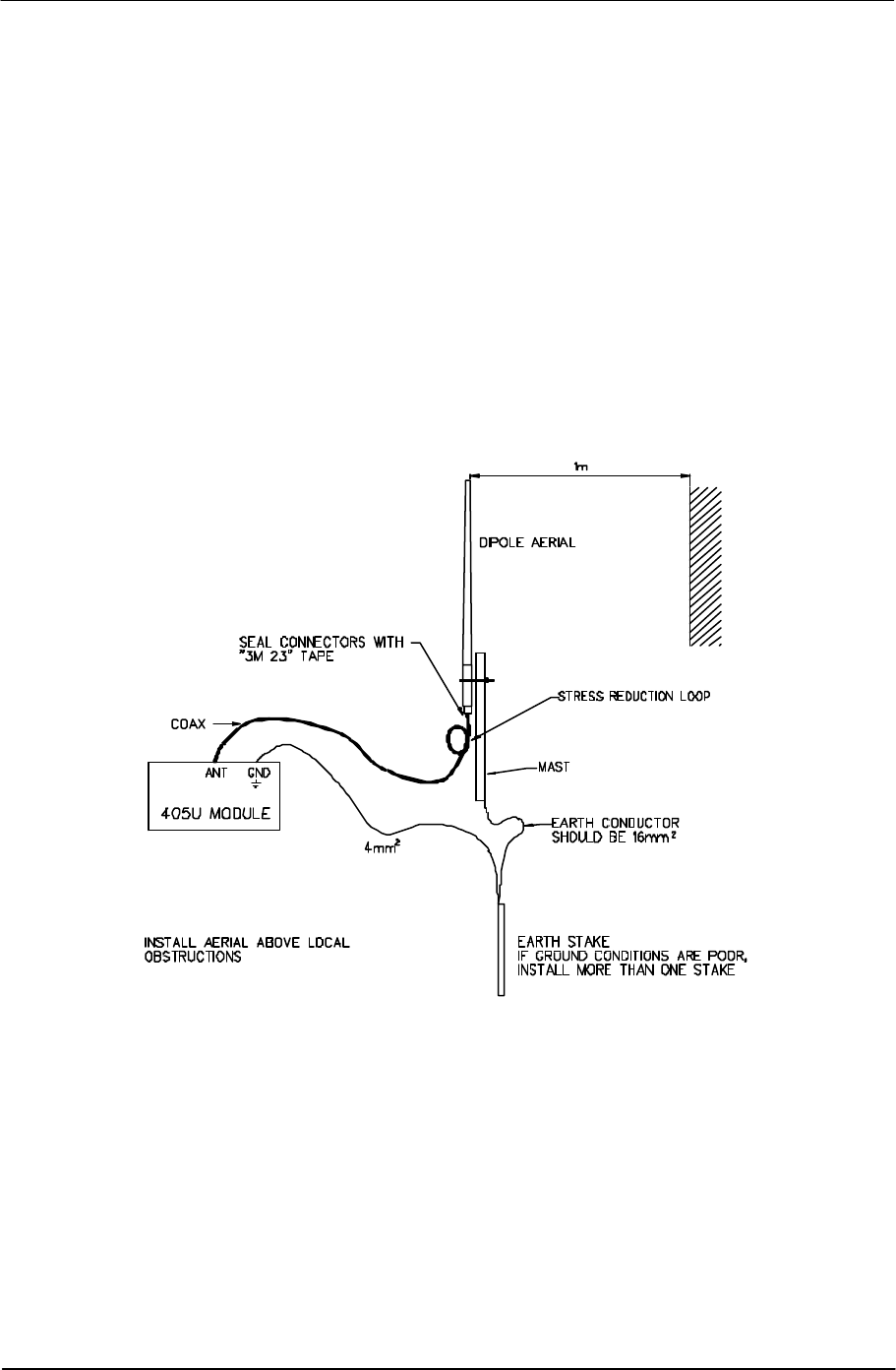
Connections between the aerial and coaxial cable should be carefully taped to prevent
ingress of moisture. Moisture ingress in the coaxial cable is a common cause for problems
with radio systems, as it greatly increases the radio losses. We recommend that the
connection be taped with a layer of PVC insulating tape, then a layer of vulcanising tape such
as “3M 23 tape”, with a final layer of PVC insulating tape.
Where aerials are mounted on elevated masts, the masts should be effectively earthed to
avoid lightning surges. Although the 905U-D module is fitted with surge protection, additional
surge suppression devices are recommended if lightning surge problems are experienced. If
the aerial is not already shielded from lightning strike by an adjacent earthed structure, a
lightning rod may be installed above the aerial to provide shielding.
2.2.1 Dipole aerial.
A unity gain dipole is the normal aerial for use on unlicensed channels. As it does not provide
any gain, then the power transmitted from the aerial will be the same as the power out of the
module, and hence will not exceed the permitted power of the unlicensed channel.
For marginal radio paths, the following lengths are the recommended maximum for the
coaxial cable to the dipole aerial. RG58 10 metres RG213 20 metres. Note that this
applies to marginal paths only - if the radio path has a strong radio signal, then longer
lengths of cable ( and hence more cable loss) can be tolerated. If more than 20 metres of
cable is required for a marginal path installation, then a low loss cable such as RG9913
should be used. Alternatively, a higher gain aerial may be used to compensate for losses.
Dipole aerials should be mounted vertically, at least 1 metre away from a wall or mast.
2.2.2 Three element Yagi aerial.
A 3 element Yagi aerial provides approx 4 dB of gain. This may be used to compensate for
coaxial cable loss for installations with marginal radio path. Note that these aerials should not
be used if the coaxial cable lengths are less than the following minimum lengths, otherwise
the power transmitted from the aerial will exceed the power permitted for the unlicensed
channel.
RG58 10 metres
RG213 20 metres.
Yagi aerials are directional. That is, they have positive gain to the front of the aerial, but
negative gain in other directions. Hence Yagi aerials should be installed with the central
beam horizontal and must be pointed exactly in the direction of transmission to benefit from
the gain of the aerial. Also note that Yagi aerials normally have a drain hole on the folded
element - the drain hole should be located on the bottom of the installed aerial.
905U-D Radio Modem Module User Manual
Page 14 © May 2000
The Yagi aerials may be installed with the elements in a vertical plane (vertically polarised) or
in a horizontal plane (horizontally polarised). For a two station installation, with both modules
using Yagi aerials, horizontal polarisation is recommended. If there are more than two
stations transmitting to a common station, then the Yagi aerials should have vertical
polarisation, and the common (or “central”) station should have a dipole or collinear aerial.
Yagi aerials should not be used where a module is receiving messages from more than one
other module such as repeater of “base-station” situations. An omni-directional aerials such
as a dipole or a collinear aerial should be used.
2.2.3 Collinear (3dB) aerial.
A 3dB collinear aerial may be used in the same way as a 3 element Yagi to compensate for
the losses in long lengths of coaxial cable. This type of aerial is generally used at a central
site with more than one remote site. The collinear aerial looks similar to the dipole, except
that it is longer.
Chapter Two Installation
Man_905UD_2.0.doc Page 15
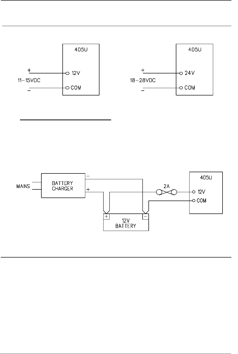
2.3 Power Supply
The 905U-D module may be powered by either a 12VDC or a 24VDC supply.
The negative side of the supply is connected to "COM" and may be connected to “ground”.
The supply negative is connected to the “GND” terminal internally. The positive side of the
supply must not be connected to earth. The DC supply may be a floating supply or
negatively grounded.
The 12V supply is suitable for an unregulated DC supply. Where battery backup is required,
a 12V battery charger may be used to supply the 905U-D module as well as charging the
battery.
The power requirements of the 905U-D units is 155mA at 12VDC or 100mA at 24VDC. The
supply is protected by an internal 1A fuse, accessible at the bottom of the unit.
2.4 Serial Connections
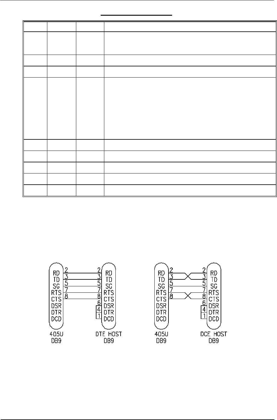
2.4.1 RS232 Serial Port
The serial port is a 9 pin DB9 female and provides for connection to a host device as well as
a PC terminal for configuration, field testing and for factory testing. This port is internally
shared with the RS485 - ensure that the RS485 is disconnected before attempting to use the
RS232 port. Communication is via standard RS232 signals. The 905U-D is configured as
DCE equipment with the pinout detailed below.
905U-D Radio Modem Module User Manual
Page 16 © May 2000
DB9 Connector Pinout
Pin Name Direction Function
1DCD Out Data carrier detect - not connected Rev. 1.03 software & earlier
Rev. 1.04 & later - driven when link is established in controlled mode
- driven always in transparent mode
2RD Out Transmit Data - Serial Data Output
3TD In Receive Data - Serial Data Input
4DTR In Data Terminal Ready - not connected Rev 1.03 & earlier,
Rev. 1.04 & later: When in controlled mode, will autodial if destination
address is configured In control mode, an inactive DTR will force the 905U-
D to low-power mode.
Rev. 1.11 & later: When in controlled mode, will autodial if destination
address is configured In control mode, an inactive DTR will force the 905U-
D stop communicating by radio. If low power mode is selected, an inactive
DTR will also force the 905U-D to low power mode.
5SG Signal Ground
6DSR Out Data Set Ready - always high when unit is powered on.
7RTS In Request to Send - hardware flow control
8CTS Out Clear to send - hardware flow control
9RI Ring indicator - not used or connected
Hardware handshaking using the CTS/RTS lines is provided. The CTS/RTS lines may be
used to reflect the status of the local unit’s input buffer, or may be configured to reflect the
status of CTS/RTS lines at the remote site. The 905U-D does not support XON/XOFF.
Example cable drawings for connection to a DTE host (a PC) or another DCE host (or
modem) are detailed below. These example are for transparent mode. Controlled mode
may require the use of DTR or DCD signals.
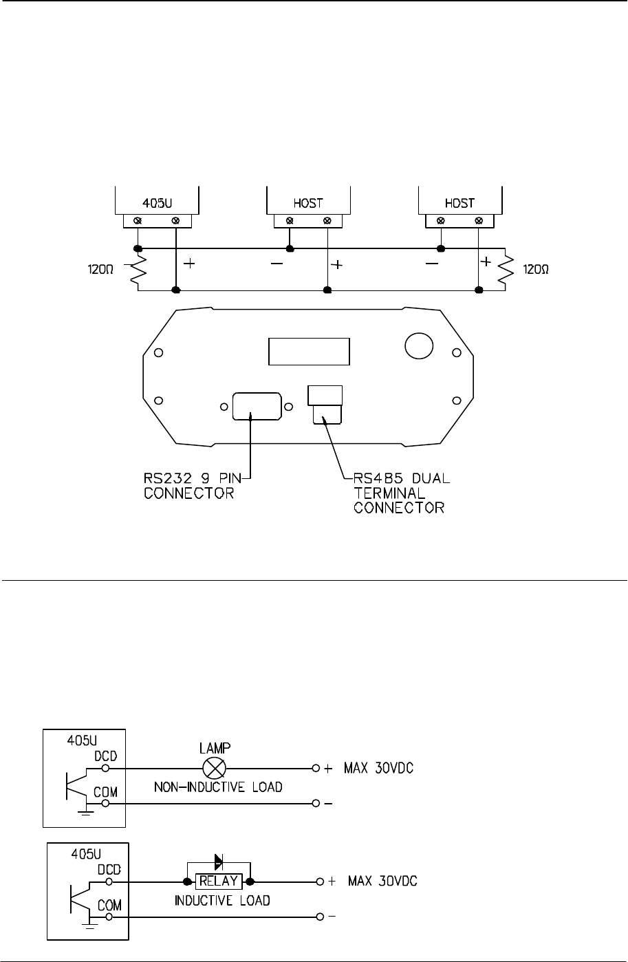
2.4.2 RS485 Serial Port
The RS485 port provides for communication between the 905U-D unit and its host device
using a multi-drop cable. Up to 32 devices may be connected in each multi-drop network.
Note that the RS485 port is shared internally with the RS232 port - make sure that the RS232
port is disconnected before using the RS485 port.
Chapter Two Installation
Man_905UD_2.0.doc Page 17
As the RS485 communication medium is shared, only one of the units in the system may
send data at any one time. Thus communication protocols based on the RS-485 standard
require some type of arbitration. The 905U-D “holds off” for three character times after
receiving data from the RS-485 port before transmitting on the RS-485 port.
RS485 is a balanced, differential standard but it is recommended that shielded, twisted pair
cable be used to interconnect modules to reduce potential RFI. An RS485 network should be
wired as indicated in the diagram below and terminated at each end of the network with a 120
ohm resistor. It is important to maintain the polarity of the two RS485 wires.
2.5 Communications OK (DCD) Output
The 905U-D provides a digital output signal to indicate “communications OK” in controlled
mode. The DCD (data carrier detect) output is “on” or active when a radio link has been
established with the destination module. The output will reset (switch “off”) if a
communications failure occurs. If the 905U-D unit does not receive an acknowledgment
message after attempting to transmit a data packet five times, it will reset the DCD output.
The output is a FET output to common, rated at 30VDC 500 mA.
- +

905U-D Radio Modem Module User Manual
Page 18 © May 2000
Chapter Three OPERATION
3.1 Power-up and Normal Operation
When power is initially connected to the 905U-D module, the module will perform internal
diagnostics to check its functions. The following table details the status of the indicating
LEDs on the front panel under normal operating conditions.
LED Indicator Condition Meaning
OK On Normal Operation
Radio RX GREEN flash
RED flash
Radio receiving data
Weak radio signal
Radio TX Flash Radio Transmitting
Serial RX GREEN flash
RED flash
GREEN continuously
Serial Port Receiving
CTS low
Configuration Mode
Serial TX GREEN flash Serial Port Transmitting
DCD On Transparent mode - always on
Controlled mode - on when
communications link is established
DCD Off Communications failure or link not
established
Other conditions indicating a fault are described in Chapter Six Troubleshooting.
Low Power Operation
The 905U-D may be forced to a low power condition where it switches off its receiver -
power consumption is reduced to approx 20% of normal. The low power condition will occur
if the 905U-D is configured for controlled mode (modes 6 or 7), AND if an autodial address is
configured, AND if the low power mode feature is configured in the “character type”
selection, AND if the DTR signal is “low” or “off”.
The use of this low power operation may be applicable in remote locations where there is a
limited power supply such as solar panels. In this situation, the DTR signal from the host
device is used to “wake-up” the 905U-D unit. The 905U-D unit will then operate normally until
the DTR signal is reset by the host device.
Chapter Three Operation
Man_905UD_2.0.doc Page 19
3.2 Serial and Radio Data
Data input at the serial port is placed into the input buffer. This buffer will store 8Kbytes of
data, and CTS control is provided on the RS232 port to prevent overflow.
When the 905U-D unit detects data in the input buffer, it initiates a radio message. The radio
message will end when the number of transmitted bytes reaches the maximum message
length (configurable by the user). The message will also end if the input buffer becomes
empty, however the radio transmitter will remain active for a delay time in case more bytes
are input at the serial port. The delay time is called the “tail time” and is configurable by the
user.
3.2.1 Character Type
The 905U-D may be configured by the user to recognise the following types of characters.
Data
Bits
Start
Bits
Stop
Bits Parity
7 1 1 even
7 1 1 odd
7 1 2 none
7 1 2 even
7 1 2 odd
8 1 1 none
8 1 1 odd
8 1 1 even
8 1 2 none
Most applications will require the character type to be the same at each 905U-D
modem in the system. Nevertheless, the character type may be configured to be
different at different 905U-D modems. Data is transmitted by radio as an eight-bit
byte without stop or start bits. If the input data is 7 data bits without parity, then the
byte transmitted by radio comprises the 7 bits plus a zero bit. If the input data is 7
data bits with parity, then the byte transmitted comprises the same byte. Input
characters with 8 bits are transmitted as just the 8 data bits, with no parity. Because
the data may be transmitted without parity, the user may configure CRC error
checking to be added to each transmitted data packet. Data is output at the
destination module based on the character type configured at that module - that is,
the start/stop bits and parity is added to the radio data.3.2.2 Serial Data Rate
The communications baud rates supported on both the RS232 serial port and the RS485
serial port are 50, 75, 150, 300, 600, 1200, 2400, 4800, 9600, 19200, and 38400 baud - the
user selects one of these rates during the configuration of the modem.

905U-D Radio Modem Module User Manual
Page 20 © May 2000
3.2.3 Radio Data Rate
The data is transmitted by radio as direct modulated synchronous data at a rate between
1200 and 9600 bits per second. The user must configure the radio data rate at each 905U-D
module. The configured radio data rates must be the same for each module in a system.
The 905U-D operates on a 12.5KHz radio channel. At 9600 bits/sec, a 905U-D unit cannot
achieve the same reliable radio range as at 4800 bits/sec or less. The range at 9600 bits/sec
is approx 70% of the normal range. On noisy radio channels, the range at 9600 baud will be
less than 70% - as the noise level increases, the range difference between 4800 baud and
9600 baud increases.
The radio message also includes the following :-
• A 40 msec leading sequence of alternating 1’s and 0’s provides the receiving unit with
time to capture and lock onto the incoming signal.
•A system address is superimposed on each message to provide discrimination
between different 905U-D systems on the same radio channel. Each 905U-D unit in
the same system must be configured with the same system address - refer Section
4, Configuration. Although other 905U-D modules will hear the radio transmissions,
because they have a different system address, the radio transmission is ignored and
no serial data is output.
•A “frame flag” appears once at the beginning of each message, and once at the end of
each message. It indicates the start and end of a message packet.
•An “idle flag” may be used to allow the message to idle for a short period after each
character is sent. This allows the 905U-D unit to effectively transfer data when the data
rate arriving at the serial port is lower than the radio data transfer rate. After each
character is sent, the transmission remains active waiting for the next character. This
is controlled by the "tail time". The tail time may be configured for between 0 and 2.55
seconds - refer Section 4, Configuration.
•The RTS status of the source unit is included in the message. In controlled mode only,
this is used to set the CTS signal at the destination module.
•In controlled mode, unit addressing is included.
• An error-check (16 bit CRC) may be configured by the user.
Up to 520 bytes of data may be transmitted in a message - the maximum message size is
configurable between 10 and 520 bytes. The data consists of a sequence of 8 bit bytes.
Start, stop and parity bits are not transmitted, but they are re-generated at the receiving unit
(if configured).
A “transmit delay” time and a “receive delay” time may also be configured. After each
message is transmitted, a 905U-D unit will not transmit another message during the transmit
delay time. After a message is received, a message will not be transmitted during the
receive delay time. These parameters may be used to fine tune and give priority to different
905U-D units in a system.
The default time of the transmit delay (70 msec) is selected for polling applications. If the
host device sends more than one poll command, the second poll message will be delayed to
allow a response to be received for the first poll message. The user can reduce this transmit
delay time if it is not required.

Chapter Three Operation
Man_905UD_2.0.doc Page 21
3.3 Transparent Mode
In transparent mode, radio messages are transmitted without unit addressing. Units do not
provide handshaking functions to control the flow of data. Every unit which receives the radio
message, and has the correct system address, will output the data. Transparent mode
operation is effectively a broadcast system.
Data received at the serial port is transmitted out of the radio port. Data received from the
radio is transmitted out of the serial port. Prior to transmitting, units will listen to the radio
channel to ensure that it is clear - units will hold off from transmitting until the radio channel
is clear. At the RS232 port, the CTS pin is high while there is space in the input data buffer.
Host devices should provide a suitable protocol to ensure that error checking, handshaking
and implementation of an appropriate re-transmission scheme is provided. This mode of
operation is particularly suited to devices designed to operate over a multidrop network, such
as PLC systems designed for operation over a RS-485 network.
One 905U-D unit may be configured as a repeater. This unit will not output data at its serial
ports. Any message received at the radio port, with the correct system address, will be re-
transmitted.
The time taken to transmit a message is :-
lead-insystem addr data error check (if configured)
|---------------|-----------------|------------------------------------------|-------------------|
40msec 2 bytes 1.9ms per byte 2 bytes
4ms @ 4.8KB @ 4.8KB 4ms @ 4.8KB
If error checking is not configured at the receiving unit, data will start to be output
approximately 1 msec after the system address has been received. If error checking is
configured, data will be output approx 2msec after the end of the message. For example, a
message with 20 bytes of data transmitted at 4800 bits/sec will be output approx 45msec
after the data is input, if there is no error checking, or 82msec after the data is input if error
checking is configured.
The time between transmissions is set by the transmit and receive hold-off times configured
by the user.
3.4 Controlled Mode
In controlled mode, data is only transferred between two modules (that is, a point to point
link). One of the modules is configured as a “master” unit and the other as a “slave” unit.
There can also be up to five intermediate repeaters in the link. Each 905U-D unit is
configured with a unit address - only the unit with an address matching the destination
address of the radio message will process the message and output the serial data.
To establish a link, the master will transmit a special “connect” message. This initial
message will not include any data. If the “slave” unit receives the initial message, and is not
already connected to another 905U-D unit, it will return an acknowledgment message. Both
units will activate their DCD LED, and also activate their DCD output signal. If the master

905U-D Radio Modem Module User Manual
Page 22 © May 2000
unit does not receive the acknowledgment, the DCD output will reset. When the connection
is made (DCD set), the 905U-D units can transmit data to each other.
The destination address may be configured two ways. The AT&Z command (see Section 4,
Configuration) enters an “auto-dial” address. The ATD command enters a “single-dial”
address. The AT&Z command only has to entered once, and the 905U-D remembers the
destination address. The ATD command has to be used each time a connection is to be
made - the 905U-D will not remember the previous destination address. If an auto-dial
address is configured, the master will transmit the “connect” message every ten seconds
until it receives an acknowledgment. If a single-dial address , the master unit will try to
connect five times - if no acknowledgment is received, a “BUSY” or “NO ANSWER”
response is sent to the host connected to the master. The host must then issue the ATD
dial command to the 905U-D before it will try to connect again.
The auto-dial operation is similar to a fixed line modem, where the destination address is
always the same. Once the auto-dial address is configured, it does not need to be entered
again. If the communications link fails (DCD resets), the master unit will automatically send
connect messages to re-establish the link.
The single-dial operation is similar to a dial-up modem. The 905U-D will make a connection
to another unit only when it is told to by the host device. If the communications link fails for
any reason, the master unit will not send a connect message until it receives another ATD
command.
Either of the two modules at the end of the link can be the “master” unit - the “master” unit
has the responsibility of establishing the radio link and periodically checking the link. Data
can be transferred in both directions - from the “master” to the “slave” and from the “slave”
to the “master”.
Once the communications channel has been established, the 905U-D unit will accept input
data and send radio messages with data. On the RS232 port, if CTS/RTS is enabled, the
CTS signal will be active when the input data buffer is not full, AND the RTS signal at the
destination module is active. The local CTS/RTS status will reflect the remote CTS/RTS
status, as well as the local input buffer. Note that CTS/RTS is disabled in the default
configuration - if this feature is required, it must be enabled (refer Configuration Chapter 4).
If CTS/RTS is not enabled, then data will be lost after the input buffer (8KB) is full.
When a 905U-D unit receives a radio message, it will check the system address and
destination address, and also the error-check (optional). If these are correct, it will return a
ACK (acknowledgment) message to the source unit. If the system address or destination
address is not correct, then no return message is sent. If the addresses are correct, but
the error-check incorrect, then a NACK (error) message is sent to the source unit.
If the source unit receives a NACK message, or does not receive any message within 1
second, it will re-transmit the same message. It will attempt to transmit the message up to
five times, with a 5 second delay between attempts. If the unit still does not receive an ACK
message after five attempts, it will reset the DCD LED, and reset the DCD output. The
unsuccessful message will be held in the input buffer until the communications link is re-
established. If the source module is the “master” unit, then it will immediately send
“connect” messages every ten seconds to the “slave” unit. If the source module was the
“slave” unit, then it will wait until it receives a “connect” message from the “master” and the
communications channel is re-established.
During normal operation, if there has been no radio activity for a period (called the “update”
period), the “master” unit will transmit the “connect” message to check the radio path. The
update period is a time configured by the user.

Chapter Three Operation
Man_905UD_2.0.doc Page 23
Establishing a Communications Link
Master Unit Slave Unit
• Listen to ensure channel is clear
•
If clear, transmit “connect”
message
• Radio TX LED flashes
-------------------> • Receives message
• Radio RX LED flashes
•
Check system and destination
address
•
If OK, set DCD LED and
output
• Radio RX LED flashes <-------------------
•
If message OK, transmit back
an ACK message.
• Radio TX LED flashes
•
Acknowledgment received okay
communication link established
• Set DCD LED and output
Successful Communications
Source Module Destination Module
• Serial data is received
• Serial RX LED flashes
• Listen to ensure channel is clear
• If clear, transmit message
• Radio TX LED flashes ------------------->
• Receive message
• Radio RX LED flashes
•
Check system and destination
address
• If OK, check error-check
• Radio RX LED flashes <-------------------
•
If message okay, transmit
back an ACK message.
• Radio TX LED flashes
• Acknowledgment received okay -
communication complete • Serial data is output
• Serial TX LED flashes

905U-D Radio Modem Module User Manual
Page 24 © May 2000
Unsuccessful Communications
Source Module Destination Module
• Listen to ensure channel is clear
• If clear, transmit message
• TX LED flashes
-------------------> • Receives message
• RX LED flashes
•
Check system and destination
address
•
If incorrect, transmit no
message and no serial output.
• Radio RX LED flashes <-------------------
•
If addresses are correct,
check error-check.
•
If incorrect, transmit a NACK
message
• TX LED flashes
•
NACK message or no message
received
• Retry up to four times ------------------->
•
If no ACK message received
after five attempts
• “Comms fail” output activated
• DCD signal and DCD LED reset
The time taken to transmit a message is :-
|------------------HEADER--------------------|--------------------DATA-----------|
lead-in system unit repeater dest. zero data error check (if configured)
40msec address addr addrs's addr byte
No. of bytes 2 1 0 - 5 1 1 no. of data bytes 2
The time for each HEADER byte is 3.8mSec @4800 bits/sec, and the time for each DATA
byte is 1.9msec @ 4800 bits/sec.
If error checking is not configured at the receiving unit, data will start to be output approx
1msec after the "zero" byte has been received. If error checking is configured, data will be
output approx 2msec after the end of the message. For example, a message with 20 bytes
of data transmitted at 4800 bits/sec with no repeaters, will be output approx 88msec after the
data is input, assuming that error checking is configured.
The time between transmissions is set by the transmit and receive hold-off times configured
by the user.
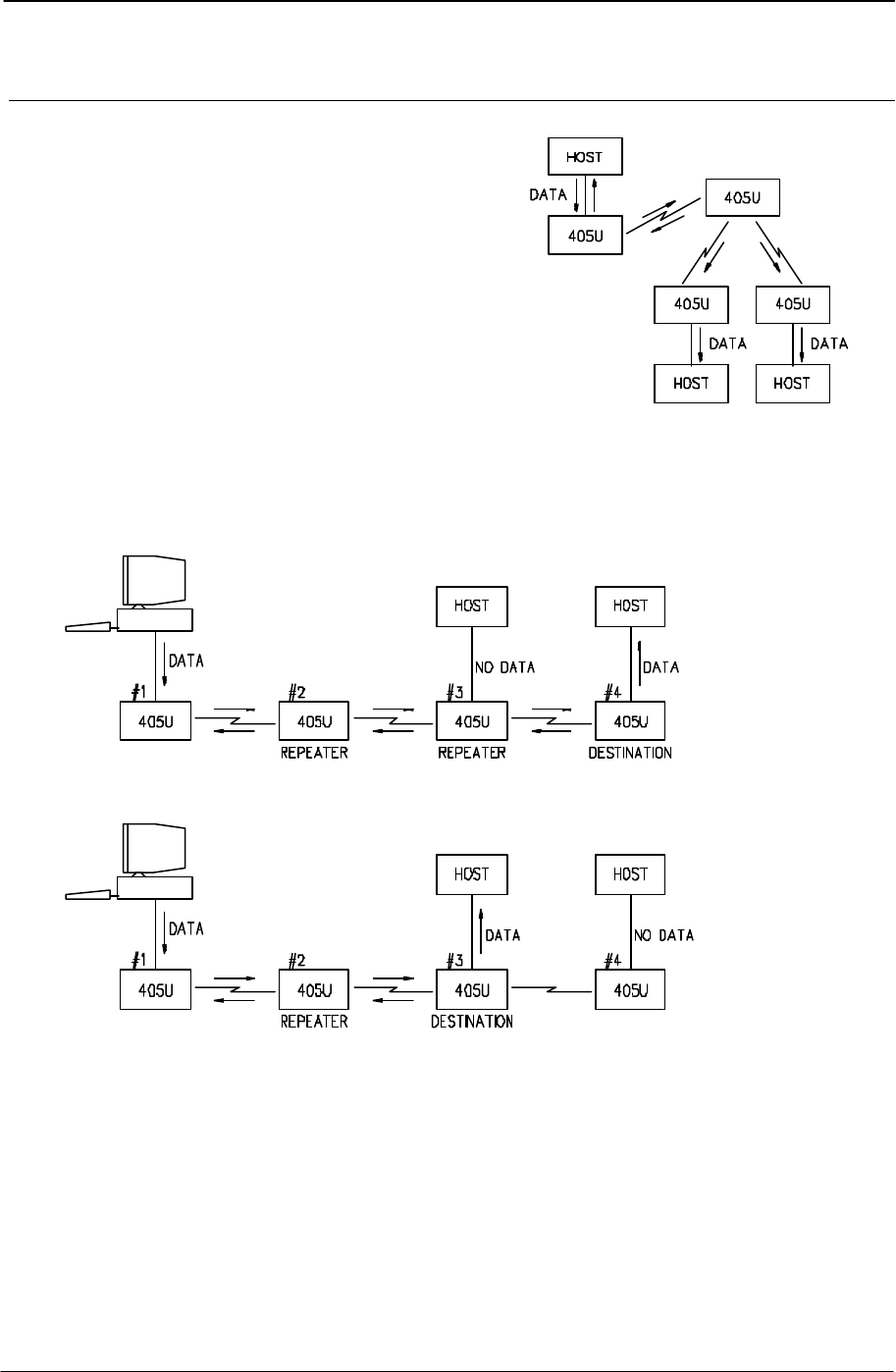
Intermediate Repeaters
Where intermediate repeaters are configured, each repeater will re-transmit the message
onto the next address. When the destination address is reached, the destination module
will return an acknowledgment (ACK) with the reverse address structure as the received
message.

Chapter Three Operation
Man_905UD_2.0.doc Page 25
If error-checking is selected, then the destination module will only return a ACK if the error
check is valid. If the error check is not valid, then a NACK message is returned. If the error-
checking function is not selected, then the destination module will return an ACK every time
it receives a message (a NACK is never sent). Each repeater will re-transmit the ACK or
NACK message until it is received by the source module.
The source module will calculate a waiting time for the acknowledgment - this time is based
on the radio baud rate, the message length (number of bytes) and the number of repeaters.
If the source module receives a NACK, or it does not receive an ACK within the waiting time,
it will transmit the same message again. The 905U-D will transmit the message up to five
times. If it does not receive an ACK after the 5th attempt, it will assume communications
failure and reset its DCD status. The unsuccessful message will not be re-transmitted and
will be lost.
Repeater Communications
Successful
Unit A
Source
• Transmit
message
Receive ACK
--->
<---
Unit B
Repeater
• Receive
message
• Re-transmit
message
• Receive ACK
• Re-transmit
ACK
--->
<---
Unit C
Repeater
• Receive
message
• Re-transmit
message
• Receive ACK
• Re-transmit
ACK
--->
<---
Unit D
Destination
• Receive
message
• Transmit
ACK
• Output data
Repeater units may also act as destination addresses for some transmissions and output
data to a host device.
3.5 What Operating Mode to Use ?
Transparent or Controlled Mode?
Transparent mode provides faster operation as the units do not acknowledge transmissions
received. However reliable operation in transparent mode will only occur if the host devices
check the messages and return acknowledgments. Generally, if a device is able to operate
on a RS485 multi-drop serial link, it is suitable for transparent mode.
Controlled mode is suitable for point-to-point links, rather than multi-point networks.
If it is not known whether a device is suitable for transparent mode, then controlled mode
should be used. If faster operation is desired, then transparent mode can be tried, and if the
system operates reliably, then transparent mode is suitable.

905U-D Radio Modem Module User Manual
Page 26 © May 2000
It is possible to configure different units in the same system with different operating modes,
however the system will not operate. A 905U-D unit configured in one mode will not process
a message received from a unit in the alternate mode.
Error Check ?
Error-checking may be configured in both transparent and controlled mode. When the error-
check is configured, two additional bytes are attached to the end of each message. These
bytes are used to detect any corruption of the data when it is received at another 905U-D unit.
When a unit with error-check configured receives a radio message, it will not output data
until it has received the whole message and ensures that the error-check is correct. If the
unit does not have error-check configured, then it will output data as it is received. Hence
operation of the units is faster if error-check is not configured.
We recommend that units in the same system have the same error-check configuration,
however it is possible for users to configure the units differently. If a unit without error-check
configured receives a message which includes an error-check, then the unit will treat the
additional two bytes as data and output them to the host device. If a unit with error-check
configured, receives a message without an error-check, it will treat the last two data bytes
as the error check - the error-check will always be incorrect and no data will be output.
Error-check is strongly recommended for controlled mode operation. If error-check is not
configured, then a 905U-D unit will transmit an acknowledgment message (ACK) whenever
it receives a radio message, without checking for errors. If error-check is configured, the
unit will only transmit an ACK message if the error-check is correct. If it is incorrect, an error
message (NACK) is returned to the source address.
Autoconnect or Host-connect modes?
If the 905U-D is connected to a PC and the PC will automatically set-up the 905U-D on start-
up, then a host-connect mode should be used (modes 0 – 3). In host-connect, the 905U-D
will start up in configuration mode.
If you want the 905U-D to start up in operating mode, then use the autoconnect modes (4 –
7).
3.6 Operating Problems
Most operating problems relate to an inadequate radio path, or radio interference. Before
installing a system, bench test the complete system with the 905U-D units near each other.
This test eliminates the radio path or interference as a factor, and ensures that the system
will operate in the way that you want. It is not necessary to connect aerials, however a small
length of wire should be inserted into the middle pin of the coaxial connector - this will act as
an aerial.
If the bench test does not give adequate performance, then you need to adjust the
configuration parameters. We recommend that you do not install the system until you are
happy with the bench test performance.
If a system gives poor performance after it is installed, check the adequacy of the radio path
- refer to the Diagnostics Section 6.

Chapter Three Operation
Man_905UD_2.0.doc Page 27
Interference will only cause a problem if the amplitude of the interference is comparable to
the radio signal from the 905U-D units. If the interference level is relatively small, then it will
not affect the performance of the system. If interference is causing a problem, try to improve
the normal radio level by mounting the aerials higher or in a better location. This not always
possible.
System performance may be improved by changing the following parameters :-
• If in transparent mode, try controlled mode.
• If configured for a radio data rate of 9600 bits/sec, reduce the rate to 4800 bits/sec.
• If large radio messages are being transmitted, reduce the maximum message length,
and transmit the data in more messages of smaller size.

905U-D Radio Modem Module User Manual
Page 28 © May 2000
Chapter Four CONFIGURATION
4.1 Before Configuring
Configuration comprises selecting parameter values for the operation of the 905U-D unit.
Before you start configuration, parameter settings must be decided.
The main parameters are :-
• Character type. You need to find out the character type of the host devices connected to
the 905U-D units. The most common character type is 8 data bits, no parity, 1 start bit
and 1 stop bit.
• Serial Data Rate. You need to find out the serial data rate used by the host devices. The
most common serial data rate is 9600 bits/sec.
• Radio Data Rate. You need to decide what radio data rate you wish to use. It does not
have to be the same as the serial data rate. Remember that the radio range for 9600
bits/sec will not be as good as that for lower data rates. Generally the data sent between
process control equipment is small, and 9600 bit/sec is not required. We recommend
that you use 4800 bits/sec unless your application requires the faster data rate.
• Operating mode . You need to decide which operating mode you wish to use. Modes are
transparent or controlled, error-checked or no-error-check, and autoconnect or host-
connect. These modes are discussed in more detail in following sections.
The other configuration parameters do not need to be selected, and are provided as a
means of "fine tuning" the operation of the 905U-D units.
Configuration may be performed from a terminal using Hayes commands, or by using the
miniature switches under the blue cover on the front of the unit.
The first step in configuration is to put the radio modem into Configuration Mode.
4.2 Configuration Mode
A 905U-D network comprises modules with the same "system" address. In controlled mode,
each module is also configured with a unit address between 0 and 127 - there can only be
127 modules in the one system. In transparent mode, modules are not configured with a unit
address, and there is no limit to the number of modules in a system (except for the capacity
of the radio channel).
4.3 Hayes Commands
The 905U-D unit may be configured by a host device using Hayes AT commands.
Configuration may be done by a user (with a PC terminal as the host device) or it can be
done automatically by a host device such as PLC or SCADA. The AT commands are ASCII
messages designed for use with conventional telephone modems.

Chapter Four Configuration
Man_905UD_2.0.doc Page 29
Before a 905U-D unit will accept Hayes commands, it must be in configuration mode. A
host device may force the unit to configuration mode by sending three “escape” characters -
“+++”. The default escape character is “+”, however this may be changed as it is one of the
configuration parameters Note that in the Host-connect operating modes, the 905U-D units
start up in configuration mode. These modes (0, 1, 2 or 3) simulate the operation of
telephone or leased-line modems, and may be used with standard host software designed
with Hayes command control.
Once in configuration mode, the 905U-D unit will accept a string of Hayes commands, and
the configuration changes made. The changes will not however be stored in permanent
memory (EEPROM) unless the Hayes command for recording the configuration (AT&W) is
sent. When the configuration changes are made, the module must be put back into its
operating mode by using the “online” Hayes command, ATO
The 905U-D will automatically change from configuration mode to operating mode if there
has been no AT command entry within a certain time. This time is one of the configuration
parameters.
The following Hayes commands are accepted by the 905U-D unit :
4.3.1 Unit Reset
The ATZ command resets the unit as if power had been switched off and on. After power up,
the configuration will be the last saved configuration - that is, the last configuration saved by
the AT&W command.
4.3.2 Storing Configuration Parameters - Write Registers
Once configuration parameters have been changed, they can be stored to non-volatile
memory with the AT&W command. When the unit is reset from power up or via the ATZ
command, the stored parameters are restored.
4.3.3 Default Values - Restore Factory Defaults
The AT&F command will reset the configuration parameters to the default values. To reset
the values and save them to nonvolatile memory, use AT&F&W
Refer to Appendix A section 1.1.10 for using the configuration switches to reset to factory
defaults.
4.3.4 S-Registers
The E405 provides 15 S-Registers to configure the operation of the unit. S-Registers may be
read using the Hayes command ATSn = xxx, where n is the number of the configuration
parameter, and xxx is the value shown below for each parameter. The entire configuration
parameters may be viewed by the Hayes command AT&V.
The configuration parameters and values are :

905U-D Radio Modem Module User Manual
Page 30 © May 2000
Operating mode (S0) ATS0 = xxx Default = 4
xxx Option Connect Mode
0Transparent mode without error-check Host
1Transparent mode with error-check Host
2Controlled mode without error-check Host
3Controlled mode with error-check Host
4Transparent mode without error-check Auto
5Transparent mode with error-check Auto
6Controlled mode without error-check Auto
7Controlled mode with error-check Auto
8Transparent mode repeater Auto
NOTE The operating mode may also be changed using the mode command (AT&Mx)
Operating modes 0 to 3 try to duplicate the operation of conventional telephone modems,
and can be used with software designed to operate with telephone modems. The 905U-D
units will start up in configuration mode, expecting Hayes command configuration. See 3.3
Controlled Mode for a description of operation.
Tail time (S1) ATS1 = xxx Default = 0
where xxx is the tail time in 10 msec increments ( xxx = 20 for 200 msec )
A tail time may be configured which keeps the radio transmitter active at the end of each
message. The maximum tail time is 2.55 seconds. The tail time value is the 8-bit binary
equivalent of the desired time in 10 msec increments.
Escape character (S2) ATS2 = xxx Default = 43 (“+”)
where xxx is the decimal ASCII value of the character. The default value is 43 (“+”).
A host device may force the unit to configuration mode by sending three “escape” characters
- “+++”. The default escape character is “+”, however this may be changed by the host
device.
ATS2 = 255 will prevent the unit entering command mode.
Maximum message length (S3) ATS3 = xxx Default = 265
where the maximum message length in bytes is equal to twice xxx plus 10, or 2 *
(xxx) + 10.
For example, ATS3 = 10 gives a maximum length of 30 bytes.
The message length parameter selects the maximum length (in bytes) of the data sent in
each radio message. The length may be selected between 10 bytes and 520 bytes. The
message length is equal to 2x(VALUE)+10, where VALUE is the decimal equivalent of the 8-
bit code entered.
Serial data rate (S4) ATS4 = xxx Default = 8
To select or change the serial data rate, enter the following VALUE code. The serial data
rate can be different at different 905U-D modules in the same system. The default value is
9600 bits/sec.

Chapter Four Configuration
Man_905UD_2.0.doc Page 31
Bits/sec xxx Bits/sec xxx
50 0 2400 6
75 1 4800 7
150 2 9600 8
300 3 19200 9
600 4 38400 10
1200 5
Radio data rate (S5) ATS5 = xxx Default = 1
To select or change the radio data rate, enter the following VALUE code. The radio data rate
should be the same at each 905U-D module in the same system. The default value is 4800
bits/sec.
Bits/sec xxx Bits/sec xxx
1200 3 4800 1
2400 2 9600 0
System address, high byte (S6) AT S6 = xxx
where xxx is the Decimal value of the first byte of the system address.
The system address comprises two bytes. Note that the high byte cannot be more
than 127.
System address, low byte (S7) ATS7 = xxx
where xxx is the Decimal value of the second byte of the system address.
Unit address (S8) ATS8 = xxx
where xxx is the decimal value of the unit address.
Note that xxx cannot be 0 (zero) or more than 127.
In controlled mode, each module is configured with a unit address between 1 and 127 -
there can only be 127 modules in the one system. In transparent mode, modules are not
configured with a unit address (the value of S8 is ignored), and there is no limit to the number
of modules in a system (except for the capacity of the radio channel).
Character Type (S9) ATS9 = x Default = 4
The Character Type parameter configures the character format, the flow control on the serial
port, and the use of DTR low power mode. The character format is the data bits, start bits,
and parity configuration. The serial port flow control may be configured for to enable or
disable RTS/CTS control. In all RS-485 applications and some RS-232 applications,
RTS/CTS control must be disabled. DTR low power mode is explained in sections 3.1 and
4.3.5 of this manual - it is only used in modes 6 or 7 with an autodial address.
The character type in the 905U-D will change as soon as the ATS9 entry is made. The
character type on the configuration terminal should change at the same time such that the
905U-D understands any subsequent commands.

905U-D Radio Modem Module User Manual
Page 32 © May 2000
NOTE : These values are valid for software version 1.11 and later. For earlier versions,
refer to your distributor. To find out the software version, use the ATI command.
Data
Bits
Start
Bits
Stop
Bits
Parity CTS/ RTS control VALUE
DTR low power
mode
VALUE
DTR normal power
mode
7 1 1 even enabled 8 40
7 1 1 odd enabled 9 41
7 1 2 even enabled 11 43
7 1 2 odd enabled 16 48
7 1 2 none enabled 3 35
8 1 1 even enabled 1 33
8 1 1 odd enabled 2 34
8 1 1 none enabled 0 32
8 1 2 none enabled 10 42
7 1 1 even disabled 12 44
7 1 1 odd disabled 13 45
7 1 2 even disabled 15 47
7 1 2 odd disabled 20 52
7 1 2 none disabled 7 39
8 1 1 even disabled 5 37
8 1 1 odd disabled 6 38
8 1 1 none disabled 4 36
8 1 2 none disabled 14 46
Display Mode (S10) ATS10 = x Default = 3
NOTE : These values are valid for software version 1.11 and later. For earlier versions,
refer to your distributor. To find out the software version, use the ATI command.
ECHO VERBOSE QUIET VALUE
“RINGING”
response
VALUE
no “RINGING”
response
Disabled Disabled Disabled 0 8
Enabled Disabled Disabled 1 9
Disabled Enabled Disabled 2 10
Enabled Enabled Disabled 3 11

Chapter Four Configuration
Man_905UD_2.0.doc Page 33
ECHO VERBOSE QUIET VALUE
“RINGING”
response
VALUE
no “RINGING”
response
Disabled Disabled Enabled 4 12
Enabled Disabled Enabled 5 13
Disabled Enabled Enabled 6 14
Enabled Enabled Enabled 7 15
NOTE: This register is accessible by the “Echo” command (ATE0, or ATE1), “Quiet”
command (ATQ0, or ATQ1), and “Verbose” command (ATVO, or ATV1)
Refer to section 4.3.6 for an explanation of the “Ringing” response feature.
Command Mode Timeout (S11) ATS11 = x Default = 60
Where x = timeout in seconds
If there has been no AT commands entered within this time, the 905U-D will automatically
change from configuration mode to operating mode. If S11 is set to 0 (zero), the 905U-D will
not automatically change, and will only change to operating mode when a ATO command is
entered.
NOTE : These values are valid for software version 1.09 and later. For earlier versions,
refer to your distributor. To find out the software version, use the ATI command.
Transmit Hold-off Time (S12) ATS12 = xxx Default = 70
where xxx is the hold-off time in 1 msec increments ( xxx = 20 for 20 msec )
A delay time may be configured such that the 405U unit will not transmit during the hold-off
time after transmitting a previous message. The maximum hold-off time is 255 msec. The
transmit hold-off time value is the 8-bit binary equivalent of the desired time in 1 msec
increments.
Receive Hold-off Time (S13) ATS13 = xxx Default = 20
where xxx is the hold-off time in 1 msec increments ( xxx = 20 for 20 msec )
A delay time may be configured such that the 405U unit will not transmit a message during
the hold-off time after receiving a message. The maximum hold-off time is 255 msec. The
receive hold-off time value is the 8-bit binary equivalent of the desired time in 1 msec
increments.
Connect Update Time (S14) ATS14 = xxx Default =
100
where xxx is the hold-off time in 0.1 minute increments ( xxx = 20 for 2 min.)
In controlled mode, the 405U unit will transmit a “connect” message if there has been no
activity on the radio channel for the update time. The connect update time value is the 8-bit
binary equivalent of the desired time in 0.1 minute increments.
4.3.5 Changing Destination/Repeater Address - autodial
The destination address and repeater addresses may be changed with the AT&Z command:-
AT&Z <first repeater>,<second repeater>,. . . . . ,<destination>

905U-D Radio Modem Module User Manual
Page 34 © May 2000
The module will automatically attempt to connect to the destination address.
For example, to set the destination address to 18 with repeater addresses 2 and 8, the
command would be - AT&Z2,8,18
If the destination address was to be 105 with no repeaters, the command would be
AT&Z105 or AT&Z105&W (this command also stores the change in permanent memory).
To clear the address values, use the command AT&Z<enter>
In modes 6 and 7, the 405U will only connect if the DTR signal is high (active). If the DTR
signal goes low (inactive), the 405U will break the connection. If low power mode is selected
at S9, then the 405U will also go to low power mode.
4.3.6 Connecting to a Remote Module – single dial
If the 405U unit is already connected to a remote module, then the connection should be
cancelled by using the “hang-up” command, ATH
To connect to a remote module, use the “dial” command
ATD <first repeater>,<second repeater>,. . . . . ,<destination>
For example, to set the destination address to 67 with repeater addresses 32 and 48, the
command would be - ATD32,48,67
The module will respond with one of the following messages :-
RINGING the module is in the process of connecting (only if “RINGING” is
selected at S10).
CONNECT the module has successfully connected
BUSY the destination module is already connected to another module
NO ANSWER the module was unable to connect to the destination address
If the destination address was to be 119 with no repeaters, the command would be ATD119.
To cancel or “hang-up” a connection, use the ATH command. The ATD and ATH
commands may be mixed. For example, ATHD119 (this command also clears the previous
connection before trying to make the new connection).
4.3.7 Reading Configuration Parameters
Host devices are able to read the value of configuration parameters by using the ATSn?
command, where "n" is the number of the configuration parameter.
4.3.8 Unit Test commands - AT&Tx
Test commands are available via the command AT&Tx, where x is the test number
requested. Many of these tests will be successful only during factory test. Refer to the
Diagnostics section of this manual (chapter 6) for a detailed listing of the test commands
available.
4.3.9 Version Information - ATI
The command ATI will result In a response from the 405U module with the software version
of the 405U. For example, “405U V1.09”

Chapter Four Configuration
Man_905UD_2.0.doc Page 35
4.3.10 Character Type - AT&Bx
This command allows configuration of the character format and flow control used on the
serial port. The x value is the same as the character type command under S-register 9.
Note: The value of this setting is also available via S-register S9
4.3.11 Character Type - AT&Mx
This command allows configuration of the operating mode. The x value is the same as the
character type command under S-register 0.
Note: The value of this setting is also available via S-register S0.
4.3.12 Verbose mode control, Local Echo control, and Quiet mode
The following commands from the host control the responses of the 405U unit to the Hayes
commands.
ATV0 numeric responses
ATV1 verbal responses
ATQ0 response displayed
ATQ1 No response displayed
ATE0 disable local echo
ATE1 enable local echo
Note: the values of these settings are also available via S-register S10.
4.3.13 Responses
The 405U modules provide responses to the Hayes commands. The responses will be
either in verbal (ASCII) or numeric, depending on the “ATV” configuration. The following
responses will be issued by the module :-
VERBAL NUMERIC MEANING
OK 0Command accepted
CONNECT 1Connected to remote unit
NO CARRIER 3Connection lost to remote unit
ERROR 4Invalid command
BUSY 7Destination unit already connected
NO ANSWER 8No response from destination address
RINGING 13 Attempting to connect to destination unit

905U-D Radio Modem Module User Manual
Page 36 © May 2000
4.4 Configuration Examples
Transparent Mode
Extending a PLC Network
Unit No. 1 Configuration
Set the module to factory default settings: AT&F
Set the system address to a random number: ATS6 = 38 ATS7 = 92
Set the serial data rate to 38400 ATS4 = 10
Set the radio data rate to 9600 ATS5 = 0
Set the character type to 7,1,2,even ATS9 = 15
Exit and save the configuration AT&W ATO
The operating mode will already be in transparent mode from the factory default settings.
The other default values for the other parameters will likely be OK.
Repeater Configuration
Set the module to factory default settings: AT&F
Set the system address to the same random number: ATS6 = 38 ATS7 = 92
Set the radio data rate to 9600 ATS5 = 0
Set the operating mode to Transparent Repeater ATS0 = 8
Exit and save the configuration AT&W ATO
Unit No. 2 Configuration
Set the module to factory default settings: AT&F
Set the system address to the same random number: ATS6 = 38 ATS7 = 92
Set the radio data rate to 9600 ATS5 = 0
Set the character type to 7,1,2,even ATS9 = 15
PLC PLC
RS485
38.4KB
405U 405U
9.6KB 9.6KB 405U
PLC
RS485
9.6KB
REPEATER
DATA = 7 DATA BITS, 1 START, 2 STOP, EVEN PARITY

Chapter Four Configuration
Man_905UD_2.0.doc Page 37
Exit and save the configuration AT&W ATO
Note that it was not necessary to set the serial data rate as 9600 is the default setting.
Controlled Mode
Point-to-point link with repeaters
Assume that default settings are used for data rates and character types. The only
configuration required is addressing.
Module #1
Set the module to factory default settings: AT&F
Set the system address to a random number: ATS6 = 17 ATS7 = 50
Set the unit address to 1 ATS8 = 1
Set the operating mode to controlled mode ATS0 = 7
Set the autodial address to 3 via 2, 100 AT&Z2,100,3
Exit and save the configuration AT&W ATO
Note that module #1 is the “master” unit in this link.
Module #2
Set the module to factory default settings: AT&F
Set the system address to the same random number: ATS6 = 17 ATS7 = 50
Set the unit address to 2 ATS8 = 2
Set the operating mode to controlled mode ATS0 = 7
Exit and save the configuration AT&W ATO
Module #3
Set the module to factory default settings: AT&F
Set the system address to the same random number: ATS6 = 17 ATS7 = 50
Set the unit address to 3 ATS8 = 3
Set the operating mode to controlled mode ATS0 = 7
Exit and save the configuration AT&W ATO
Source Repeater Repeater Destination
#1 ----------------> #2 -----------------> #100 --------------------> #3
#101
Apart from being a repeater in the 1 - 3 link, 100 is also in a separate link to 101

905U-D Radio Modem Module User Manual
Page 38 © May 2000
Module #100
Note that #100 is the master unit for a link between #100 and #101, It is also acting as
repeater in the #1 to #3 link. The system address for #100 and #101 must be the same as
the other modules so that #100 can act as a repeater.
Set the module to factory default settings: AT&F
Set the system address to the same random number: ATS6 = 17 ATS7 = 50
Set the unit address to 100 ATS8 = 100
Set the operating mode to controlled mode ATS0 = 7
Set the autodial address to 101 AT&Z101
Exit and save the configuration AT&W ATO
The configuration for #101 is not shown as it is not part of the active link.

Chapter Five Specifications
Man_905UD_2.0.doc Page 39
Chapter Five SPECIFICATIONS
General
EMC specification EN55022 (CISPR 22)
EN 50082-1,
EN 300 683
AS 3548
89/336/EEC
Radio specification MPT 1329 UK
EN-300-220
AS 4268.2 AUST
RFS29 NZ
458 MHz, 500 mW EIRP
430 - 450 MHz, 10 - 500 mW
472 MHz, 100 mW EIRP
458 MHz, 500 mW EIRP
Housing 130 x 185 x 60mm
DIN rail mount
Powder-coated, extruded
aluminium
Terminal blocks Removable Suitable for 2.5sqmm conductors
LED indication OK operation, Serial RX
and TX, Radio RX and
TX, DCD active
Operating Temperature -20 to 60 degrees C
Power Supply
Nominal supply 12VDC or 24VDC
12V supply 11.3 - 15 VDC Overvoltage and reverse voltage
protected
24V supply 18 - 28 VDC Overvoltage and reverse voltage
protected
Current Drain @ 12VDC 150 mA quiescent
30mA (low power mode)
During transmission 500mA
Current Drain @ 24VDC 80 mA quiescent
20mA (low power mode)
During transmission 300mA
Radio Transceiver
Single channel synthesised, selectable
band 4MHz Direct frequency modulation
Frequency 405 - 490 MHz
220 – 235 MHz
12.5 kHz channel spacing
Transmit power 10 - 500 mW
5W
405-490 MHz
220 – 235 MHz

905U-D Radio Modem Module User Manual
Page 40 © May 2000
Spurious emissions RX - <-57 dBm
TX - <-37 dBm
Frequency Stability +/- 1. 0 kHz
Receiver Sensitivity 0.4uV at 12dB SINAD
Signal detect / RSSI -120 to -80 dBm
Expected line-of-sight range
@ 4800 bit/sec
2 km @ 10mW EIRP
5 km @ 100mW EIRP
10 km @ 500 mW EIRP
Range may be extended by up to
5 intermediate modules as
repeaters, in controlled mode
Aerial Connector Female BNC coaxial Protected by gas discharge
surge arrestor
Serial Ports
RS232 Port DB9 male DCE RTS/CTS/DCD hardware signals
provided
RS485 Port 2 pin terminal block Typical distance 1 - 2 km
Data rate (bit/sec) -
configurable 50, 75, 150, 300, 600,
1200, 2400, 4800, 9600,
19200, 38400
Byte format 7 or 8 data bits Stop/start/parity bits configurable
Output Signal
DCD (communications)
active FET output, 30 VDC
500mA In transparent mode:
always ON.
In controlled mode:
ON when radio link is established
System Parameters
Operating modes Transparent mode
Controlled mode
Broadcast system
Addressed communications with
acknowledged
System address Configurable 15 bit
User Configuration Hayes commands from host
device.
Or via on-board DIP switches

Chapter Six Troubleshooting
Man_905UD_2.0.doc Page 41
Chapter Six TROUBLESHOOTING
6.1 Diagnostics Chart
INDICATOR CONDITION MEANING
OK LED OFF Continuously • Power supply failure
• CPU failure
OK LED ON Continuously • Normal Operation
Radio TX LED ON Flashes briefly • Radio transmitting
Radio RX LED ON GREEN flash
RED flash
• Radio receiving data
• Weak radio signal
Serial RX LED ON GREEN flash
RED flash
GREEN continuously
• Serial Port Receiving
• CTS low
• Configuration Mode
Radio RX and Serial RX LED
ON RED flash for 10 secs
after power up
•
Configuration corruption
(EEPROM failure)
Serial TX LED ON Flashes briefly • Serial port transmitting
DCD LED ON Continuously
•
In transparent mode, always
on.
•
In controlled mode, a radio link
has been established.
The green OK LED on the front panel indicates correct operation of the unit. This LED
extinguishes on failure as described above. When the OK LED extinguishes shutdown state
is indicated. On processor failure, or on failure during startup diagnostics, the unit shuts
down, and remains in shutdown until the fault is rectified.
6.2 Test Functions
6.2.1 Radio Testing using Tone Reversals
This function allows the unit to be configured to continuously transmit a sequence of alternate
zeros and ones on the radio. This function provides the facility to check VSWR of aerials
during installation, as well as checking the fade margin of the path between two units (see
below - received signal strength indication).
905U-D Radio Modem Module User Manual
Page 42 © May 2000
The tone reversals function is initiated by setting all of the DIL switches to ON, and holding
down the red button for approximately 5 seconds (until the Serial RX LED indicates RED
continuously). On releasing the button, the RX LED will flash continuously, and the TX LED
will light, indicating that the radio transmitter is on.
6.2.2 Diagnostic Functions - AT&Tx
To aid in the checking and setup of the 405U unit diagnostic functions in the 405U are
provided using the standard Hayes AT commands. Several of these functions are used
during factory test, and will not work correctly if the unit is not connected to the factory test jig.
The table below outlines the functions of the various tests:
Test Command Function
AT&T0 Factory test only
AT&T1 Factory test only
AT&T2 Factory test only
AT&T3 Factory test only
AT&T4 Factory test only
AT&T5 Internal RAM test
AT&T6 Nonvolatile Memory (EEPROM) test
AT&T7 Configuration Switch test
AT&T8 Received Signal Strength Display
AT&T9 Transmit Tone reversals
AT&TA BER Test - Master
AT&TB BER Test - Slave
AT&TC BER Test – Two direction
The tests most useful for diagnosing system problems are “received signal strength
display” and “transmit tone reversals”.
AT&T9 - Transmit Tone Reversals
This provides the same function as described above (Tone Reversals). This function may be
used to check VSWR of aerials, and may be used in conjunction with the Signal option
(described below) to check the path between two 405U units.
AT&T8 - Received Signal Strength Display
This option provides for testing the radio path between two 405U units. Although a pair of
units may communicate successfully, radio communication may be affected by a range of
influences, including atmospheric conditions, changing landscape, degradation of aerials or
co-axial cable, low battery voltage etc. Fade margin is an indication of how far a radio path
can deteriorate before reliable communication becomes unreliable.

Chapter Six Troubleshooting
Man_905UD_2.0.doc Page 43
When using this feature, the current value of the received signal strength is displayed in dBm
(decibels referenced to 1 mW). This value is updated every half second. To check the radio
path between two units, select the signal option at the local unit. The remote unit may then be
set up for tone reversals (refer 1 above) and the signal level read from the computer screen.
We have selected a bit error rate (BER) of 1 in 300 as the point at which unreliable
communications occurs. The following table lists the minimum signal required for reliable
communications (BER > 1 in 300). A system with the minimum signal level will not stay
reliable under all conditions, because of changing factors such as environmental conditions.
A fade margin of at least 15 dB should be allowed for to take account of these factors. The
table also lists our recommended minimum signal level, taking this margin into account.
Radio Baud Rate Minimum signal for BER
= 1 in 300 Recommended minimum
signal
9600 -100 dBm -85 dBm
4800 -107 dBm -92 dBm
In areas experiencing radio interference or high background noise, reliable communications
may not be achievable even with this signal level. To determine if interference is occurring,
the signal option may be selected without any other 405U units active. In a normal radio
environment, a reading of at most -110 dBm should be displayed. If a reading above this
value is displayed (for example -100 dBm), then the received signal strength from the remote
should be at least 15 dB higher than the background noise for reliable communication.
Example:
AT&T8 Displayed signal level of background noise/interference
RSSI Display - press a key to exit
-88 dBm
AT&T8 Minimum signal level for reliable comms
RSSI Display - press a key to exit
-73 dBm
When using directional aerials (YAGI aerials) this feature may be used to align the aerial in
the correct direction by selecting the peak signal when moving the aerial. Setup the remote
unit to transmit tone reversals as described above, and observe the signal indication while
adjusting the orientation of the aerial. A peak in signal level indicates optimum orientation of
the aerial.

905U-D Radio Modem Module User Manual
Page 44 © May 2000
6.2.3 Bit Error Rate Test (BER)
BER may be tested in one direction by typing AT&TA (BER master) at the sending unit and
typing AT&TB (BER slave) at the receiving unit. The sending unit will repeatedly send
pseudo-random frames, and the receiving unit will check these frames for errors. If a
terminal is connected to the sending unit, the pseudo-random data is displayed as it is
transmitted. If a terminal is connected to the receiving unit, then the test results are
displayed.
An example of the receiving unit’s display is here.
Test Errors Extra Level TotErr TotTest
109 0 0 -77dBm 3109 kbit
Test -the sequence number of the last received frame
Errors -the number of bit errors in the last received frame
Extra -any extra characters at the end of the frame (negative numbers indicate
frame dropped out early)
Level -the RSSI level when the frame was received.
TotErr -The total errors received during this test.
TotTest -The total number of bits sent (in 1000’s)
Occasionally during testing, the following may be displayed:
Test Errors Extra Level TotErr TotTest
Bad Header
This indicated that the header information has been corrupted. Corrupted headers do not
contribute to the bit errors, which are calculated only on the 1,000 bit frame.
BER testing may also be performed in both directions simultaneously. In this case, a remote
module is set up to Transparent mode repeater operation, (ATS0=8) and the BER test is
performed on the local module using the command AT&TC (loopback Bit Error Test). In this
case, the display is identical to the display on the BER slave unit above, but the displayed bit
errors are a total for the round trip, so will be the sum of the bit errors in both directions.

Chapter Seven Warranty and Service
Man_905UD_2.0.doc Page 45
Chapter Seven WARRANTY & SERVICE
We are pleased that you have purchased this product. Your purchase is guaranteed against
defects for a 365 day warranty period, commencing from the date of purchase.
This warranty does not extend to:
-Failures caused by the operation of the equipment outside the particular product's
specification.
-use of the 405U module not in accordance with this User Manual, or
-abuse, misuse, neglect or damage by external causes, or
-repairs, alterations, or modifications undertaken other than by an authorised Service
Agent.
Full product specifications and maintenance instructions are available from your Service
Agent, your source of purchase, or from the master distributor in your country upon request
and should be noted if you are in any doubt about the operating environment for your
equipment purchase
In the unlikely event of your purchase being faulty, your warranty extends to free repair or
replacement of the faulty unit, after its receipt at the master distributor in your country. Our
warranty does not include transport or insurance charges relating to a warranty claim.
This warranty does not indemnify the purchaser of products for any consequential claim for
damages or loss of operations or profits.
Should you wish to make a warranty claim, or obtain service, please forward the module to
the nearest authorised Service Agent along with proof of purchase. For details of authorised
Service Agents, contact your sales distributor.
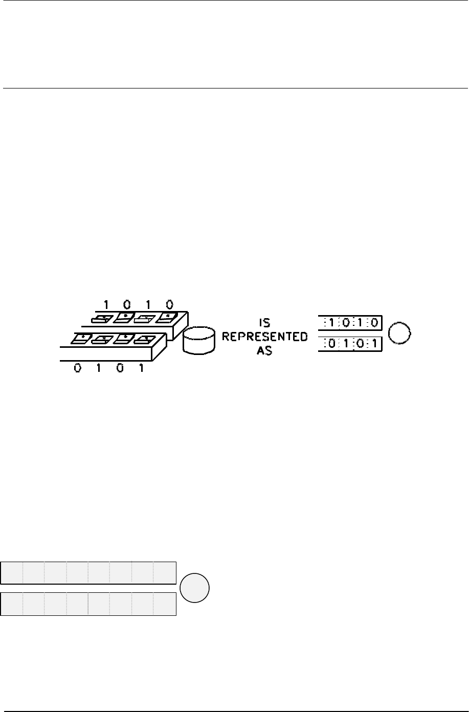
905U-D Radio Modem Module User Manual
Page 46 © May 2000
Appendix A Switch Configuration
1.0 Introduction
In order to configure the 405U unit, or to change the configuration, the unit must be placed
into Configuration Mode. When in this mode, the unit will not operate as transparent or
controlled mode.
Module configuration may be performed using the on-board miniature (DIP) switches or from
the host device using Hayes AT command codes (refer to Section 4.3).
In order to avoid radio interference between adjacent 405U networks, a "system address" is
required to be configured. Each module within the one network must have the same system
address. The system address may be any number between 1 and 32 767.
To simplify matters, the system address may be just an arbitrary pattern of off and on
switches (“0”s and “1”s) - it is not important what the actual system address value is - as
long as each module in the network has the same switch pattern for the system address. A
system address of zero (all 0's) is not acceptable.
NOTE:
The configuration used in your system should be recorded for future reference. This information
will be required when the unit is initially configured, if a unit is replaced, if the system is to be
expanded, or if units are tested with the internal Self Test configuration. Configuration record
sheets are provided at the end of this manual. These sheets should be used to assist in planning
the network for your application and to have the data readily available for entry.
Entering a system address puts the 405U in Configuration Mode:
• Carefully remove the blue plastic cover in the centre of the module to reveal the switches
and red pushbutton underneath.
•
Set the chosen system address on the
DIP switches as shown. Make sure the
switch marked ‘0’ is set to ‘0’. Other
switches can be in any chosen position.
•
Press the red button for approx. 3
seconds - until the Serial RX LED
indicates RED.
•
The Serial RX LED will indicate GREEN
on release of the button indicating the unit
is in “Configuration Mode”
-------SYSTEM--------
---------ADDRESS--------
0
Appendix A Switch Configuration
Man_905UD_2.0.doc Page 47
Once the module is in configuration mode, transparent or controlled mode may be selected.
This is achieved by entering in another switch pattern. If transparent mode is selected, no
further configuration is required, and the module will automatically exit configuration mode. If
controlled mode is selected, further entries are required for the addressing of the
communications link.
1.0.1 Default Configuration
The default configuration is the configuration set in the factory. When you receive new
modules, they will have this configuration. The default configuration is transparent mode
without error-checking, autoconnect mode, with serial data rates of 9600 bits/sec, and radio
data rate of 4800 bit/sec. The serial ports will be set up for a byte format of 8 data bits, 1
start bit, 1 stop bit and no parity. Further details of default settings are included in Appendix A
– Section 1.1.10.
1.0.2 Transparent Mode
To select transparent mode the following switch pattern is entered after the system address
is entered :-
• First enter the system address
• Enter the switch pattern
•
Configuration mode will automatically
exit and the RX LED will reset.
The operating mode will be set to mode 4 (Transparent mode without error check). Refer to
Configuration Parameters in Appendix A – Section 1.1.
1.0.3 Controlled Mode
In controlled mode, each module within a network must be configured with an individual unit
address. Each module must have a unique unit address within the one system. Each
controlled mode system may have up to 127 modules. Addresses may be in the range 1 to
127. Note that address 0 is not accepted - if this address is entered, the module exits
configuration mode and you must start configuration again. This address is coded in binary
on the DIP switches. Appendix B lists the switch code for each address between 1 and 127.
To configure controlled mode, switch patterns are entered consecutively with the module
unit address, any repeater addresses and the destination address. These switch patterns
are entered after the system address has been entered. If more than one repeater is used in
the radio link, then each repeater address is entered in order, starting with the first repeater
and then the next repeater and so on. Up to five repeater addresses may be entered. If only
one repeater is used, then only one repeater address is entered. If three are used, then
three repeater addresses are entered - etc. The destination address is always the last
address entered. If there are no repeaters used, then the destination address is entered
immediately after the unit address. After the destination address is entered, a switch pattern
with all “0”s (all the switches off) is entered. The module then exits configuration mode.
0 0 0 0 0 0 0 0
0 0 0 0 0 0 0 0
905U-D Radio Modem Module User Manual
Page 48 © May 2000
Note that repeater and destination addresses are only entered for the “master” unit
in each link. For “slave” units, only the unit address is entered. For modules which will just
act as a repeater unit, just a unit address need be entered. For these modules, enter the exit
pattern of all zero’s after the unit address.
To select controlled mode the following switch pattern is entered after the system address
has been entered.
• First enter the system address
• Enter the unit address
•
Enter the repeater addresses (if any)
in order, and then enter the
destination address.
• When all of the addresses have
been entered
• Enter all 0’s
•
Configuration mde will automatically
exit and the RX LED will reset.
The operating mode will be set to Controlled Mode with Error-Checking (mode 7) - refer to
Appendix A – Section 1.1, Configuration Parameters.
Example
Module #1 Configuration
Module #1 is configured as the master unit .
• System address 100 1001 0001 0010.
Source Repeater Repeater Destination
#1 ----------------> #2 -----------------> #100 --------------------> #3
#101
Apart from being a repeater in the 1 - 3 link, 100 is also in a separate link to 101
----- ADDRESS -----
0 0 0 0 0 0 0 1
0 0 0 0 0 0 0 0
0 1 0 0 1 0 0 1
0
0 0 0 0 0 0 0 0
0 0 0 1 0 0 1 0
Appendix A Switch Configuration
Man_905UD_2.0.doc Page 49
• Unit address is 0000001 (#1)
• First repeater address is 0000010 (#2)
•
Second repeater address is 1100100
(#100)
• Destination address is 0000011 (#3)
• Configuration complete
Module #2 Configuration
Module #2 is the first repeater. As there is no host device connected, a destination address
is not required.
• System address 100100100010010.
• Unit address is 0000010 (#2)
0 0 0 0 0 0 0 1
0 0 0 0 0 0 0 1
0 0 0 0 0 0 0 1
0 0 0 0 0 0 0 1
0 0 0 0 0 0 0 0
0 1 0 0 1 0 0 1
0 0 0 0 0 0 0 1
0 0 0 0 0 0 0 1
0 0 0 0 0 0 1 0
0 1 1 0 0 1 0 0
0 0 0 0 0 0 1 1
0 0 0 0 0 0 0 0
0 0 0 1 0 0 1 0
0 0 0 0 0 0 1 0
905U-D Radio Modem Module User Manual
Page 50 © May 2000
• Configuration complete
Module #100 Configuration
Module #100 is the second repeater in the link between #1 and #3. It also has a host device
and transmits data to #101. It is configured as the “master” unit for the #100 - #101 link. As it
has the unit address #100, it will also act as a repeater for #1 - #3. Note that the system
address for #100 and #101 has to be the same as #1 and #3.
If module #100 was the “slave” unit for the #100 - #101 link, then only the unit address would
be required for the #100 configuration.
• System address 100100100010010.
• Unit address is 1100100 (#100)
• Destination address is 1100101 (#101)
• Configuration complete
0 0 0 0 0 0 0 0
0 1 0 0 1 0 0 1
0 0 0 0 0 0 0 1
0 0 0 0 0 0 0 1
0 0 0 0 0 0 0 0
0 0 0 0 0 0 0 0
0 0 0 1 0 0 1 0
0 1 1 0 0 1 0 0
0 1 1 0 0 1 0 1
0 0 0 0 0 0 0 0
Appendix A Switch Configuration
Man_905UD_2.0.doc Page 51
Module #3 Configuration
As module #3 is the “slave” unit for this link, only the unit address is required for the
configuration.
• System address 100100100010010.
• Unit address is 0000011 (#3)
• Configuration complete
1.1 Configuration Parameters
Configuration parameters may be configured or changed at any time by entering the
appropriate switch code and pressing the red button continuously until the Serial RX LED
indicates RED. When the red button is released, the RX LED will return to normal. The
405U module will reset and start-up as if power had been disconnected.
Each parameter has a default value which is set in the factory. All of the parameters do not
need to be set - only those which you wish to change..
Each switch entry will be of the following pattern :-
•
Enter the code with the parameter
code (PARAM) and the parameter
value (VALUE) chosen and press
button until RX LED lights.
--PARAM--
-----------VALUE----------
0 1 0 0 1 0 0 1
0 0 0 0 0 0 0 1
0 0 0 0 0 0 0 0
1 0 0 0
0 0 0 1 0 0 1 0
0 0 0 0 0 0 1 1
0 0 0 0 0 0 0 0

905U-D Radio Modem Module User Manual
Page 52 © May 2000
1.1.1 Operating Mode
PARAM = 0 0 0 0 Default = 0 0 0 0 0 1 0 0
Mode Value Option Connect
Mode
00 0 0 0 0 0 0 0 Transparent mode without error-check Host
10 0 0 0 0 0 0 1 Transparent mode with error-check Host
20 0 0 0 0 0 1 0 Controlled mode without error-check Host
30 0 0 0 0 0 1 1 Controlled mode with error-check Host
40 0 0 0 0 1 0 0 Transparent mode without error-check Auto
50 0 0 0 0 1 0 1 Transparent mode with error-check Auto
60 0 0 0 0 1 1 0 Controlled mode without error-check Auto
70 0 0 0 0 1 1 1 Controlled mode with error-check Auto
80 0 0 0 1 0 0 0 Transparent mode repeater Auto
Host connect modes are suitable for use with host devices that can drive leased-line or dial-
up modems. Units in Host-connect mode power-up in Configuration Mode. They require a
Hayes command to make a connection. eg. ATO for Leased-line or ATDxx - see 4.3 Hayes
Commands.
Autoconnect modes will automatically establish a connection on power-up and automatically
try to re-establish a connection if it is lost.
Note that the programming of a system, unit or destination address using the DIL switches
will cause the unit to default to Mode 4 transparent mode or Mode 7 controlled mode. For this
reason, the Operating Mode parameter must be programmed (if mode 4 or mode 7 are
unsuitable) after entering the address information.
1.1.2 Tail Time
PARAM = 0 0 0 1 Default = 0 0 0 0 0 0 0 0
A tail time may be configured which keeps the radio channel open at the end of each
message. The maximum tail time is 2.55 seconds. The tail time value is the 8-bit binary
equivalent of the desired time in 10 msec increments. Hence for a desired tail time of 100
msec, a VALUE code of ten (00001010 ) is entered. For the maximum time of 2.55 secs, a
VALUE code of 255 (11111111) is entered. The default tail time is zero seconds - that is, no
tail time. Appendix A lists the 8-bit patterns for each value between 0 and 255.
1.1.3 Message Length
PARAM = 0 0 1 1 Default = 1 1 1 1 1 1 1 1
The message length parameter selects the maximum length (in bytes) of the data sent in
each radio message. The length may be selected between 10 bytes and 520 bytes. The
message length is equal to 2x(VALUE)+10, where VALUE is the decimal equivalent of the 8-
bit code entered.

Appendix A Switch Configuration
Man_905UD_2.0.doc Page 53
Hence for a desired message of 10 bytes, a VALUE code of zero (00000000 ) is entered.
For the maximum length of 520 bytes, a MESSL code of 255 (11111111) is entered. The
default message length is 520 bytes.
1.1.4 Serial Data Rate
PARAM = 0 1 0 0 Default = 0 0 0 0 1 0 0 0
To select or change the serial data rate, enter the following VALUE code. The serial data
rate can be different at different 405U modules in the same system. The default value is
9600 bits/sec.
Serial Data Rate VALUE
(bits/sec)
50 0 0 0 0 0 0 0 0
75 0 0 0 0 0 0 0 1
150 0 0 0 0 0 0 1 0
300 0 0 0 0 0 0 1 1
600 0 0 0 0 0 1 0 0
1200 0 0 0 0 0 1 0 1
Serial Data Rate VALUE
(bits/sec)
2400 0 0 0 0 0 1 1 0
4800 0 0 0 0 0 1 1 1
9600 0 0 0 0 1 0 0 0
19200 0 0 0 0 1 0 0 1
38400 0 0 0 0 1 0 1 0
1.1.5 Radio Data Rate
PARAM = 0 1 0 1 Default = 0 0 0 0 0 0 0 1
To select or change the radio data rate, enter the following VALUE code. The radio data rate
should be the same at each 405U module in the same system. The default value is 4800
bits/sec.
Radio Data Rate VALUE
(bits/sec)
1200 0 0 0 0 0 0 1 1
2400 0 0 0 0 0 0 1 0
Radio Data Rate VALUE
(bits/sec)
4800 0 0 0 0 0 0 0 1
9600 0 0 0 0 0 0 0 0
1.1.6 Transmit Hold-off Time
PARAM = 1 1 0 0 Default = 0 0 1 0 1 0 0 0
A delay time may be configured such that the 405U unit will not transmit during the hold-off
time after transmitting a previous message. The maximum hold-off time is 255 msec. The
transmit hold-off time value is the 8-bit binary equivalent of the desired time in 1 msec
increments. Hence for a desired hold-off time of 10 msec, a VALUE code of ten (00001010 )
is entered. For the maximum time of 255 msec, a VALUE code of 255 (11111111) is
entered. The default tail time is 40 msec. Appendix B lists the 8-bit patterns for each value
between 0 and 255.
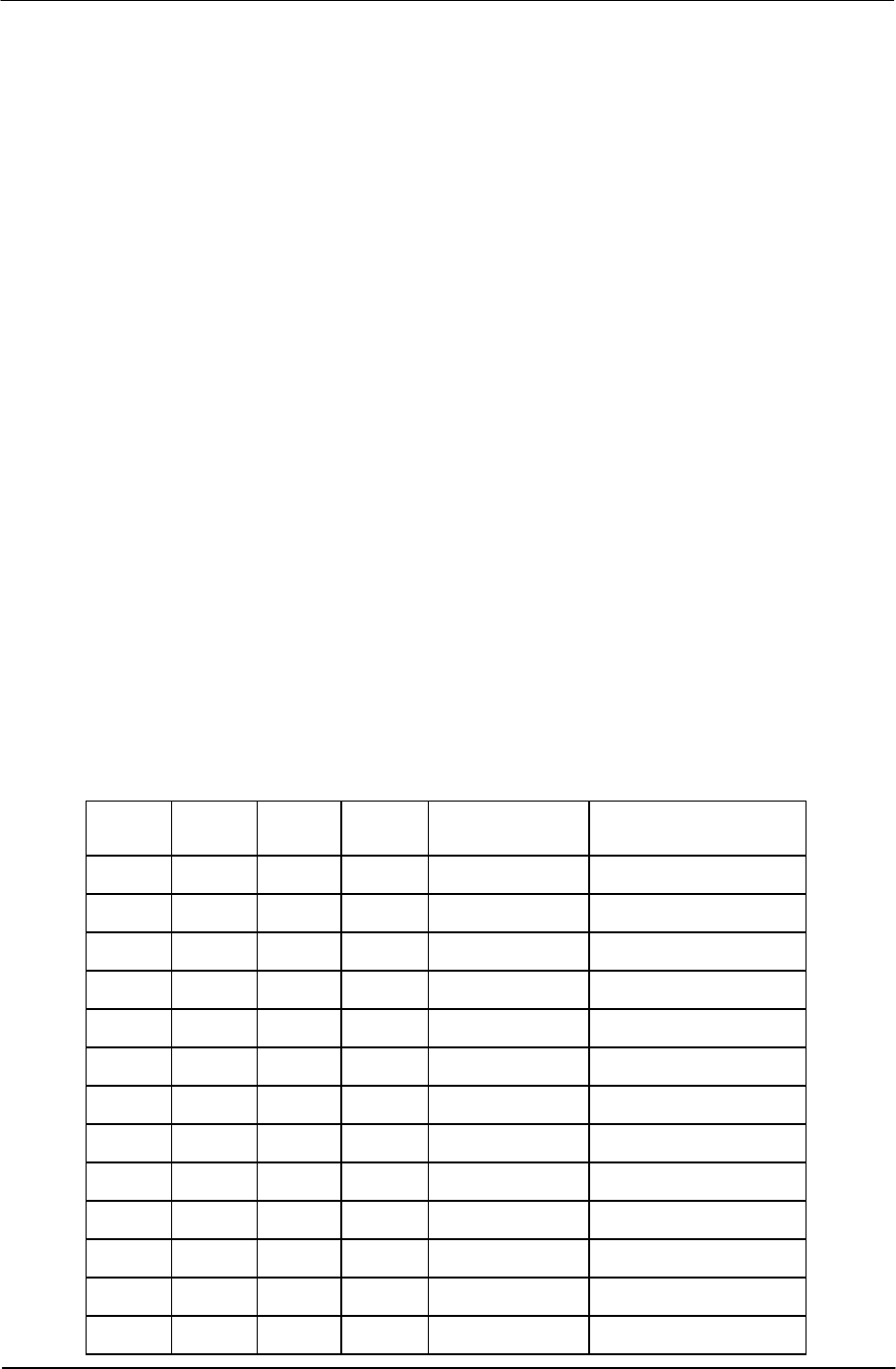
405U Radio Modem Module User Manual
Page 54 © May 2000
1.1.7 Receive Hold-off Time
PARAM = 1 1 0 1 Default = 0 0 0 1 0 1 0 0
A delay time may be configured such that the 405U unit will not transmit a message during
the hold-off time after receiving a message. The maximum hold-off time is 255 msec. The
receive hold-off time value is the 8-bit binary equivalent of the desired time in 1 msec
increments. Hence for a desired hold-off time of 10 msec, a VALUE code of ten (00001010 )
is entered. For the maximum time of 255 msec, a VALUE code of 255 (11111111) is
entered. The default tail time is 20 msec. Appendix B lists the 8-bit patterns for each value
between 0 and 255.
1.1.8 Character Type
PARAM = 1 0 0 1 Default = 0 0 0 0 0 1 0 0
To select or change the data character type, enter the following VALUE code. The
character type should match the type of data handled by the host device connected to that
405U module. The character type is normally the same at each 405U module in the same
system.
The Character Type parameter configures both the character format and the flow control on
the serial port. The character format comprises the number of data bits, start bits, and parity
configuration. The serial port flow control may be configured to enable or disable RTS/CTS
control. In all RS-485 applications and some RS-232 applications, RTS/CTS control must be
disabled.
The default type is 8 data bits, 1 start bit, 1 stop bit, no parity, with disabled RTS/CTS.
NOTE: These values are valid for software Versions 1.11 or later, with configurations
requiring DTR Low Power Mode only. Modules requiring DTR Normal Power Mode
will need to be configured using Register S9 - Character Type.
Data
Bits Start
Bits Stop
Bits Parity CTS/ RTS
control VALUE
8 1 1 none enabled 0 0 0 0 0 0 0 0
811even enabled 0 0 0 0 0 0 0 1
8 1 1 odd enabled 0 0 0 0 0 0 1 0
7 1 2 none enabled 0 0 0 0 0 0 1 1
711even enabled 0 0 0 0 1 0 0 0
7 1 1 odd enabled 0 0 0 0 1 0 0 1
8 1 2 none enabled 0 0 0 0 1 0 1 0
712even enabled 0 0 0 0 1 0 1 1
7 1 2 odd enabled 0 0 0 1 0 0 0 0
8 1 1 none disabled 0 0 0 0 0 1 0 0
811even disabled 0 0 0 0 0 1 0 1
8 1 1 odd disabled 0 0 0 0 0 1 1 0
7 1 2 none disabled 0 0 0 0 0 1 1 1
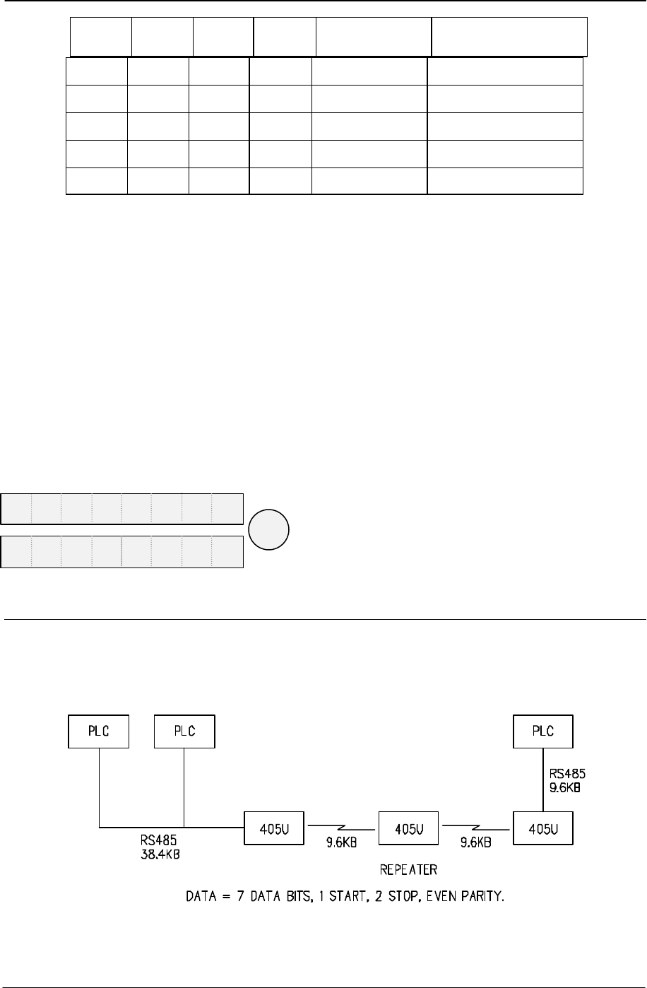
Appendix A Switch Configuration
Man_905UD_2.0.doc Page 55
Data
Bits Start
Bits Stop
Bits Parity CTS/ RTS
control VALUE
711even disabled 0 0 0 0 1 1 0 0
7 1 1 odd disabled 0 0 0 0 1 1 0 1
8 1 2 none disabled 0 0 0 0 1 1 1 0
712even disabled 0 0 0 0 1 1 1 1
7 1 2 odd disabled 0 0 0 1 0 1 0 0
1.1.9 Connect Update Time
PARAM = 1 1 1 0 Default = 0 1 1 0 0 1 0 0
In controlled mode, the 405U unit will transmit a “connect” message if there has been no
activity on the radio channel for the update time. The connect update time value is the 8-bit
binary equivalent of the desired time in 0.1 minute increments. Hence for a desired hold-off
time of 1 minute, a VALUE code of ten (00001010 ) is entered. For the maximum time of
25.5 minutes, a VALUE code of 255 (11111111) is entered. The default update time is 10
minutes. Appendix B lists the 8-bit patterns for each value between 0 and 255.
1.1.10 Reset to Factory Default Settings
The following switch pattern will reset the configurations to the factory default values. Note
that this also includes the original factory set system address.
•
Enter the code with and press button
until Serial RX LED indicates RED.
1.2 Configuration Example
Transparent Mode
Extending a PLC Network
1 1 0 0 0 0 0 0
0 0 0 0 0 0 0 0
405U Radio Modem Module User Manual
Page 56 © May 2000
Unit No. 1 Configuration
• Set the System Address
•
Press the red button for approx. 3
seconds - until the Serial RX LED
indicates RED.
•
Configuration mde will automatically
exit as Transparent Mode
•
Set serial data rate to 38400 bits/sec
and press button until RX LED lights.
•
Set radio data rate to 9600 bits/sec
and press button until RX LED lights.
•
Set the character type to 7,1,2,E,
disabled control, and press button
until RX LED lights.
Note that as RS485 is used, the
CTS/RTS control is disabled.
Repeater Configuration
• Set the System Address
•
Press the red button for approx. 3
seconds - until the RX LED comes on.
0 0 0 1 0 1 0 1
0 0 0 0 0 0 0 0
1 0 0 0 0 1 0 0
1 0 0 0 0 1 0 1
1 0 0 0 1 0 0 1
0 0 0 1 0 1 0 1
0 0 0 1 0 1 0 1
0 0 0 0 0 0 0 0
0 0 0 0 1 0 1 0
0 0 0 0 0 0 1 1
0 0 0 0 0 1 1 1
0 0 0 1 0 1 0 1
Appendix A Switch Configuration
Man_905UD_2.0.doc Page 57
•
Configuration mde will automatically
exit as Transparent Mode
•
Set Operating Mode to Transparent
Repeater and press button until RX
LED lights.
Unit No. 2 Configuration
• Set the System Address
•
Press the red button for approx. 3
seconds - until the RX LED comes on.
•
Configuration mde will automatically
exit as Transparent Mode
•
Set serial data rate to 9600 bits/sec
and press button until RX LED lights.
•
Set radio data rate to 9600 bits/sec
and press button until RX LED lights.
•
Set the character type to 7,1,2,E,
disabled control, and press button
until RX LED lights.
Note that as RS485 is used, the
CTS/RTS control is disabled.
0 0 0 0 0 0 0 0
1 0 0 0 0 0 0 0
0 0 0 1 0 1 0 1
0 0 0 0 0 0 0 0
1 0 0 0 0 1 0 0
1 0 0 0 0 1 0 1
1 0 0 0 1 0 0 1
0 0 0 0 0 0 0 0
0 0 0 0 1 0 0 0
0 0 0 1 0 1 0 1
0 0 0 0 0 0 0 0
0 0 0 0 1 0 0 0
0 0 0 0 0 0 1 1
0 0 0 0 0 1 1 1

405U Radio Modem Module User Manual
Page 58 © May 2000
Appendix B DECIMAL TO BINARY TABLE
VALUE 8 BIT PATTERN VALUE 8 BIT PATTERN VALUE 8 BIT PATTERN
00 0 0 0 0 0 0 0 38 0 0 1 0 0 1 1 0 76 0 1 0 0 1 1 0 0
10 0 0 0 0 0 0 1 39 0 0 1 0 0 1 1 1 77 0 1 0 0 1 1 0 1
20 0 0 0 0 0 1 0 40 0 0 1 0 1 0 0 0 78 0 1 0 0 1 1 1 0
30 0 0 0 0 0 1 1 41 0 0 1 0 1 0 0 1 79 0 1 0 0 1 1 1 1
40 0 0 0 0 1 0 0 42 0 0 1 0 1 0 1 0 80 0 1 0 1 0 0 0 0
50 0 0 0 0 1 0 1 43 0 0 1 0 1 0 1 1 81 0 1 0 1 0 0 0 1
60 0 0 0 0 1 1 0 44 0 0 1 0 1 1 0 0 82 0 1 0 1 0 0 1 0
70 0 0 0 0 1 1 1 45 0 0 1 0 1 1 0 1 83 0 1 0 1 0 0 1 1
80 0 0 0 1 0 0 0 46 0 0 1 0 1 1 1 0 84 0 1 0 1 0 1 0 0
90 0 0 0 1 0 0 1 47 0 0 1 0 1 1 1 1 85 0 1 0 1 0 1 0 1
10 0 0 0 0 1 0 1 0 48 0 0 1 1 0 0 0 0 86 0 1 0 1 0 1 1 0
11 0 0 0 0 1 0 1 1 49 0 0 1 1 0 0 0 1 87 0 1 0 1 0 1 1 1
12 0 0 0 0 1 1 0 0 50 0 0 1 1 0 0 1 0 88 0 1 0 1 1 0 0 0
13 0 0 0 0 1 1 0 1 51 0 0 1 1 0 0 1 1 89 0 1 0 1 1 0 0 1
14 0 0 0 0 1 1 1 0 52 0 0 1 1 0 1 0 0 90 0 1 0 1 1 0 1 0
15 0 0 0 0 1 1 1 1 53 0 0 1 1 0 1 0 1 91 0 1 0 1 1 0 1 1
16 0 0 0 1 0 0 0 0 54 0 0 1 1 0 1 1 0 92 0 1 0 1 1 1 0 0
17 0 0 0 1 0 0 0 1 55 0 0 1 1 0 1 1 1 93 0 1 0 1 1 1 0 1
18 0 0 0 1 0 0 1 0 56 0 0 1 1 1 0 0 0 94 0 1 0 1 1 1 1 0
19 0 0 0 1 0 0 1 1 57 0 0 1 1 1 0 0 1 95 0 1 0 1 1 1 1 1
20 0 0 0 1 0 1 0 0 58 0 0 1 1 1 0 1 0 96 0 1 1 0 0 0 0 0
21 0 0 0 1 0 1 0 1 59 0 0 1 1 1 0 1 1 97 0 1 1 0 0 0 0 1
22 0 0 0 1 0 1 1 0 60 0 0 1 1 1 1 0 0 98 0 1 1 0 0 0 1 0
23 0 0 0 1 0 1 1 1 61 0 0 1 1 1 1 0 1 99 0 1 1 0 0 0 1 1
24 0 0 0 1 1 0 0 0 62 0 0 1 1 1 1 1 0 100 0 1 1 0 0 1 0 0
25 0 0 0 1 1 0 0 1 63 0 0 1 1 1 1 1 1 101 0 1 1 0 0 1 0 1
26 0 0 0 1 1 0 1 0 64 0 1 0 0 0 0 0 0 102 0 1 1 0 0 1 1 0
27 0 0 0 1 1 0 1 1 65 0 1 0 0 0 0 0 1 103 0 1 1 0 0 1 1 1
28 0 0 0 1 1 1 0 0 66 0 1 0 0 0 0 1 0 104 0 1 1 0 1 0 0 0
29 0 0 0 1 1 1 0 1 67 0 1 0 0 0 0 1 1 105 0 1 1 0 1 0 0 1
30 0 0 0 1 1 1 1 0 68 0 1 0 0 0 1 0 0 106 0 1 1 0 1 0 1 0
31 0 0 0 1 1 1 1 1 69 0 1 0 0 0 1 0 1 107 0 1 1 0 1 0 1 1
32 0 0 1 0 0 0 0 0 70 0 1 0 0 0 1 1 0 108 0 1 1 0 1 1 0 0
33 0 0 1 0 0 0 0 1 71 0 1 0 0 0 1 1 1 109 0 1 1 0 1 1 0 1
34 0 0 1 0 0 0 1 0 72 0 1 0 0 1 0 0 0 110 0 1 1 0 1 1 1 0
35 0 0 1 0 0 0 1 1 73 0 1 0 0 1 0 0 1 111 0 1 1 0 1 1 1 1
36 0 0 1 0 0 1 0 0 74 0 1 0 0 1 0 1 0 112 0 1 1 1 0 0 0 0
37 0 0 1 0 0 1 0 1 75 0 1 0 0 1 0 1 1 113 0 1 1 1 0 0 0 1

Appendix B Decimal to Binary Table
Man_905UD_2.0.doc Page 59
VALUE 8 BIT PATTERN VALUE 8 BIT PATTERN VALUE 8 BIT PATTERN
114 0 1 1 1 0 0 1 0 151 1 0 0 1 0 1 1 1 188 1 0 1 1 1 1 0 0
115 0 1 1 1 0 0 1 1 152 1 0 0 1 1 0 0 0 189 1 0 1 1 1 1 0 1
116 0 1 1 1 0 1 0 0 153 1 0 0 1 1 0 0 1 190 1 0 1 1 1 1 1 0
117 0 1 1 1 0 1 0 1 154 1 0 0 1 1 0 1 0 191 1 0 1 1 1 1 1 1
118 0 1 1 1 0 1 1 0 155 1 0 0 1 1 0 1 1 192 1 1 0 0 0 0 0 0
119 0 1 1 1 0 1 1 1 156 1 0 0 1 1 1 0 0 193 1 1 0 0 0 0 0 1
120 0 1 1 1 1 0 0 0 157 1 0 0 1 1 1 0 1 194 1 1 0 0 0 0 1 0
121 0 1 1 1 1 0 0 1 158 1 0 0 1 1 1 1 0 195 1 1 0 0 0 0 1 1
122 0 1 1 1 1 0 1 0 159 1 0 0 1 1 1 1 1 196 1 1 0 0 0 1 0 0
123 0 1 1 1 1 0 1 1 160 1 0 1 0 0 0 0 0 197 1 1 0 0 0 1 0 1
124 0 1 1 1 1 1 0 0 161 1 0 1 0 0 0 0 1 198 1 1 0 0 0 1 1 0
125 0 1 1 1 1 1 0 1 162 1 0 1 0 0 0 1 0 199 1 1 0 0 0 1 1 1
126 0 1 1 1 1 1 1 0 163 1 0 1 0 0 0 1 1 200 1 1 0 0 1 0 0 0
127 0 1 1 1 1 1 1 1 164 1 0 1 0 0 1 0 0 201 1 1 0 0 1 0 0 1
128 1 0 0 0 0 0 0 0 165 1 0 1 0 0 1 0 1 202 1 1 0 0 1 0 1 0
129 1 0 0 0 0 0 0 1 166 1 0 1 0 0 1 1 0 203 1 1 0 0 1 0 1 1
130 1 0 0 0 0 0 1 0 167 1 0 1 0 0 1 1 1 204 1 1 0 0 1 1 0 0
131 1 0 0 0 0 0 1 1 168 1 0 1 0 1 0 0 0 205 1 1 0 0 1 1 0 1
132 1 0 0 0 0 1 0 0 169 1 0 1 0 1 0 0 1 206 1 1 0 0 1 1 1 0
133 1 0 0 0 0 1 0 1 170 1 0 1 0 1 0 1 0 207 1 1 0 0 1 1 1 1
134 1 0 0 0 0 1 1 0 171 1 0 1 0 1 0 1 1 208 1 1 0 1 0 0 0 0
135 1 0 0 0 0 1 1 1 172 1 0 1 0 1 1 0 0 209 1 1 0 1 0 0 0 1
136 1 0 0 0 1 0 0 0 173 1 0 1 0 1 1 0 1 210 1 1 0 1 0 0 1 0
137 1 0 0 0 1 0 0 1 174 1 0 1 0 1 1 1 0 211 1 1 0 1 0 0 1 1
138 1 0 0 0 1 0 1 0 175 1 0 1 0 1 1 1 1 212 1 1 0 1 0 1 0 0
139 1 0 0 0 1 0 1 1 176 1 0 1 1 0 0 0 0 213 1 1 0 1 0 1 0 1
140 1 0 0 0 1 1 0 0 177 1 0 1 1 0 0 0 1 214 1 1 0 1 0 1 1 0
141 1 0 0 0 1 1 0 1 178 1 0 1 1 0 0 1 0 215 1 1 0 1 0 1 1 1
142 1 0 0 0 1 1 1 0 179 1 0 1 1 0 0 1 1 216 1 1 0 1 1 0 0 0
143 1 0 0 0 1 1 1 1 180 1 0 1 1 0 1 0 0 217 1 1 0 1 1 0 0 1
144 1 0 0 1 0 0 0 0 181 1 0 1 1 0 1 0 1 218 1 1 0 1 1 0 1 0
145 1 0 0 1 0 0 0 1 182 1 0 1 1 0 1 1 0 219 1 1 0 1 1 0 1 1
146 1 0 0 1 0 0 1 0 183 1 0 1 1 0 1 1 1 220 1 1 0 1 1 1 0 0
147 1 0 0 1 0 0 1 1 184 1 0 1 1 1 0 0 0 221 1 1 0 1 1 1 0 1
148 1 0 0 1 0 1 0 0 185 1 0 1 1 1 0 0 1 222 1 1 0 1 1 1 1 0
149 1 0 0 1 0 1 0 1 186 1 0 1 1 1 0 1 0 223 1 1 0 1 1 1 1 1
150 1 0 0 1 0 1 1 0 187 1 0 1 1 1 0 1 1 224 1 1 1 0 0 0 0 0
225 1 1 1 0 0 0 0 1 236 1 1 1 0 1 1 0 0 247 1 1 1 1 0 1 1 1
226 1 1 1 0 0 0 1 0 237 1 1 1 0 1 1 0 1 248 1 1 1 1 1 0 0 0
227 1 1 1 0 0 0 1 1 238 1 1 1 0 1 1 1 0 249 1 1 1 1 1 0 0 1
228 1 1 1 0 0 1 0 0 239 1 1 1 0 1 1 1 1 250 1 1 1 1 1 0 1 0
229 1 1 1 0 0 1 0 1 240 1 1 1 1 0 0 0 0 251 1 1 1 1 1 0 1 1

405U Radio Modem Module User Manual
Page 60 © May 2000
VALUE 8 BIT PATTERN VALUE 8 BIT PATTERN VALUE 8 BIT PATTERN
230 1 1 1 0 0 1 1 0 241 1 1 1 1 0 0 0 1 252 1 1 1 1 1 1 0 0
231 1 1 1 0 0 1 1 1 242 1 1 1 1 0 0 1 0 253 1 1 1 1 1 1 0 1
232 1 1 1 0 1 0 0 0 243 1 1 1 1 0 0 1 1 254 1 1 1 1 1 1 1 0
233 1 1 1 0 1 0 0 1 244 1 1 1 1 0 1 0 0 255 1 1 1 1 1 1 1 1
234 1 1 1 0 1 0 1 0 245 1 1 1 1 0 1 0 1
235 1 1 1 0 1 0 1 1 246 1 1 1 1 0 1 1 0