ELTA ADT406S ELT model ADT 406S (Emergency Locator Transmitter) User Manual ADT 406 S User Handbook
ELTA ELT model ADT 406S (Emergency Locator Transmitter) ADT 406 S User Handbook
UserManual.wiki
>
ELTA
>
ADT406S User Manual
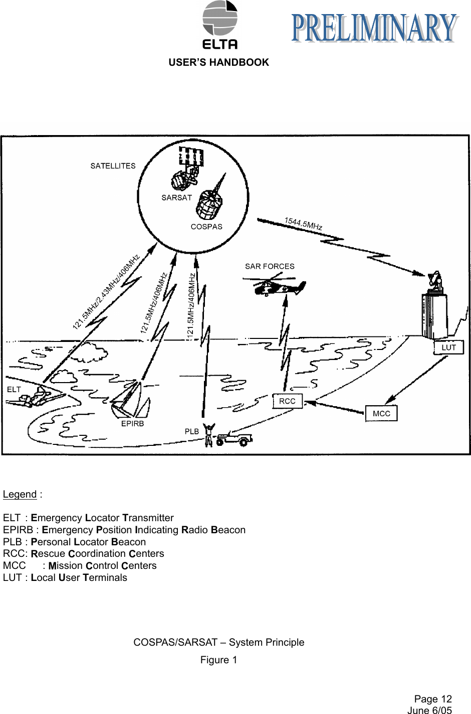
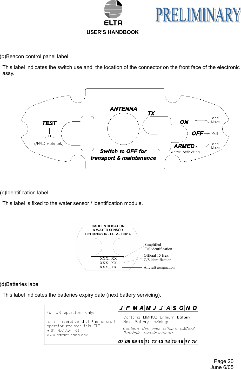
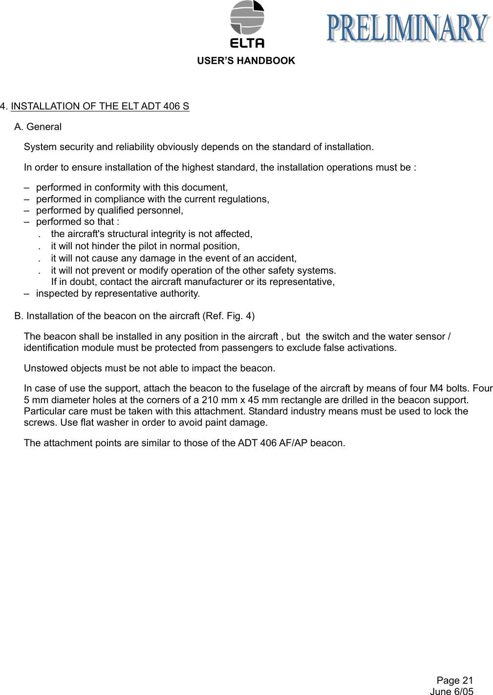
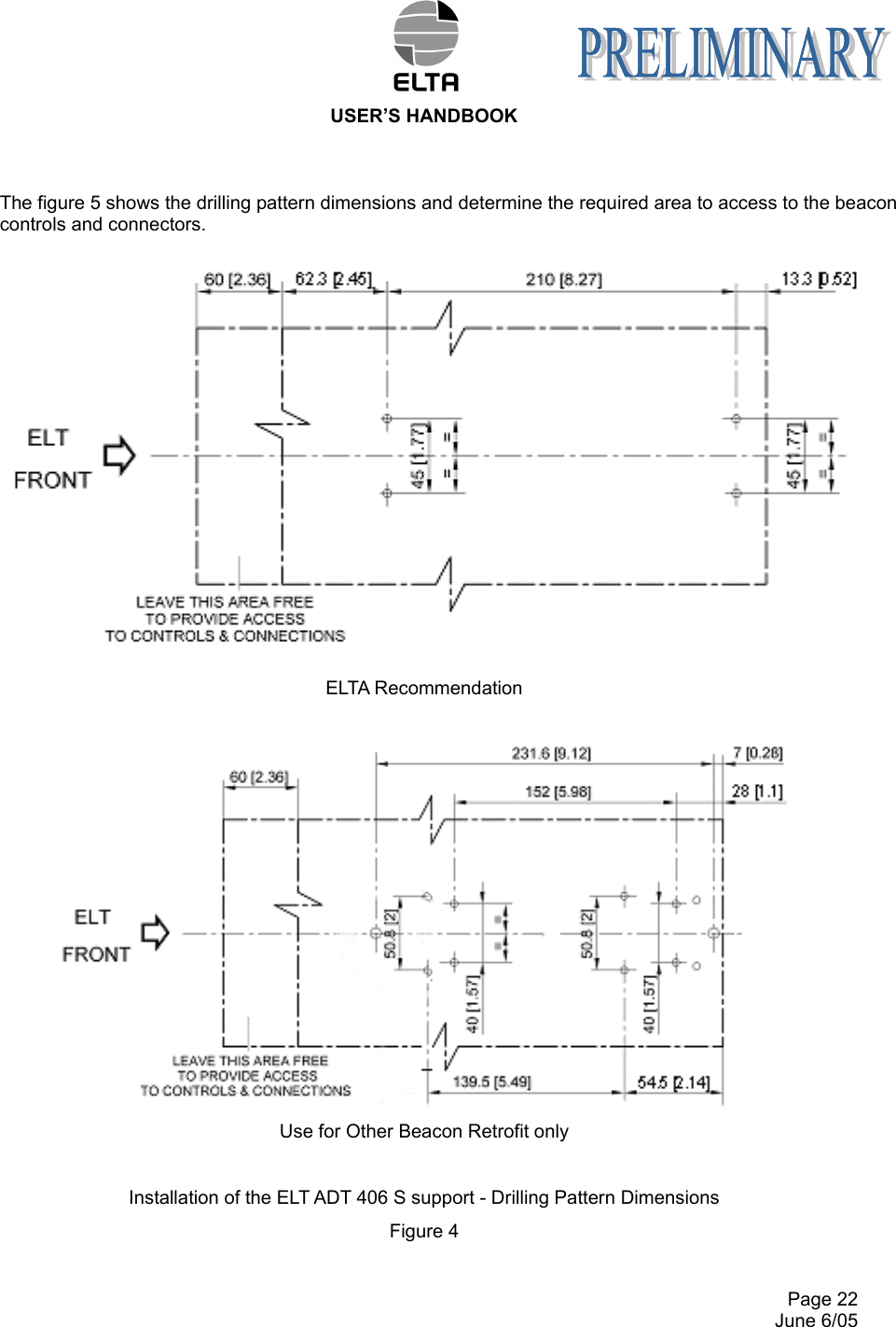
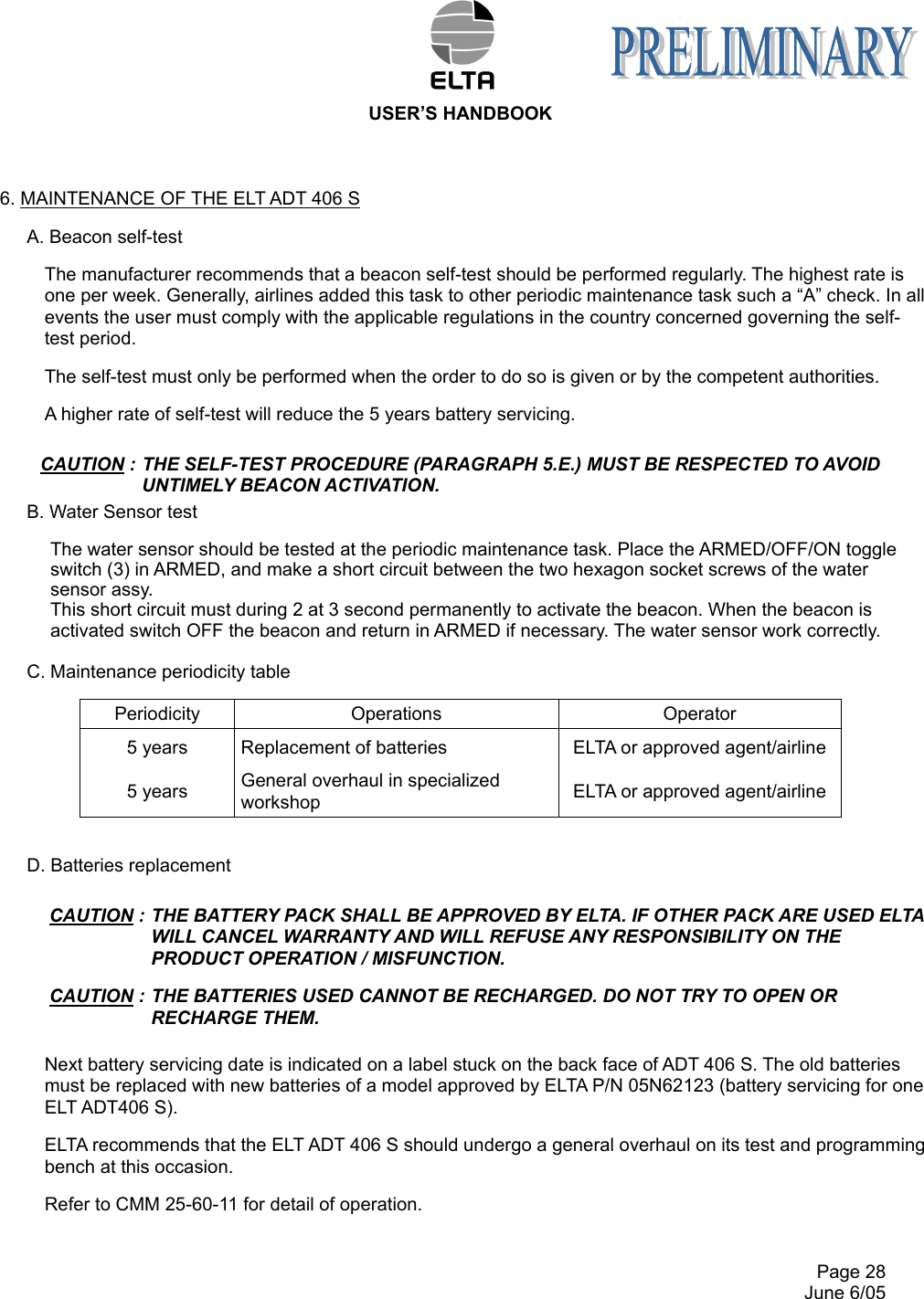
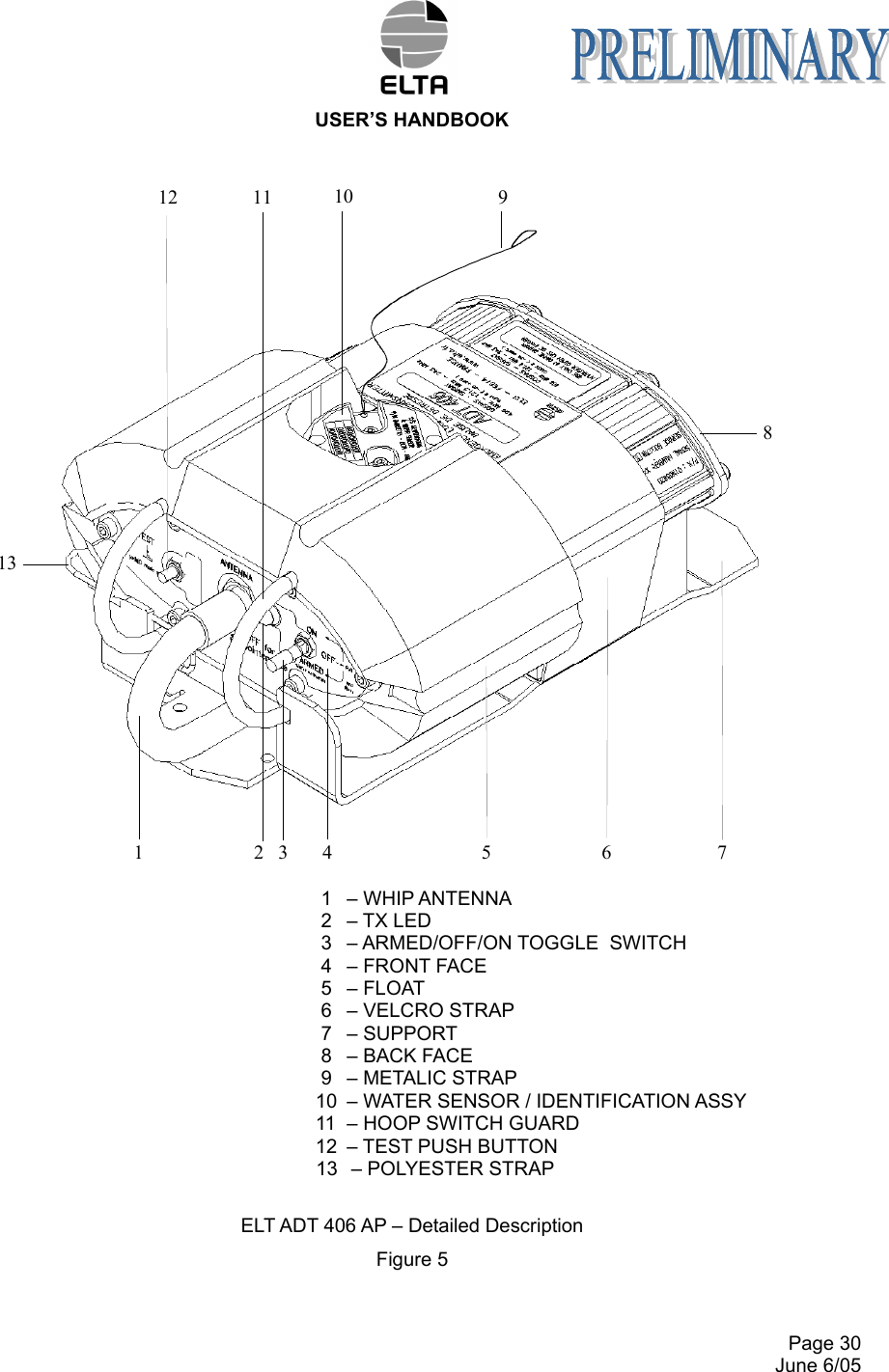
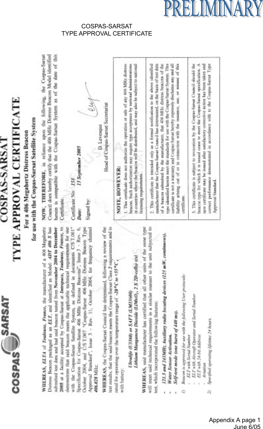
ADT 406 S User Handbook
Navigation menu
Upload a User Manual
Namespaces
Wiki Guide
HTML
PDF
Info
Views
User Manual
Discussion / Help
Navigation