EMCEE Broadcast MBSR100MW Repeater User Manual
EMCEE Broadcast Products Repeater Users Manual
Users Manual

Installation Instructions
MBSR100MW MBS Repeater
U.S Patent #4,791,717, #5,020,149
READ ME FIRST!
The EMCEE MBSR100MW is a professional solid state low-power MBS Band
retransmission repeater (amplifier) system, and is formed from a combination of
a pre-selected frequency input pre-amplifier module (P/N 701007) and an AGC
controlled 100mW post amplifier module (P/N 50800002A), each of which is in a
separate chassis/housing and connected via an interconnecting coaxial cable
with Type ‘N’ connectors. The system is capable of retransmitting from one to
seven MBS channels with either analog NTSC or digital modulation. The system
provides an end-to-end electrical gain typically 70dB. The system has no
frequency generating circuits, and as such, the output carrier frequencies and
modulations are dependent on the inputs. The pre-amplifier contains a dual
section inter-digital filter system which provides high Q MBS pass-band circuitry
at the input stage. This is to prevent pre-amplifier input overloads due to out of
band interference from close stations utilizing the LBS and UBS bands. The input
pre-selection also prevents the retransmission of out of band signals. The output
(post) amplifier has an output AGC range of 20dB, with a 20dBm average power
output power threshold. The AGC circuitry is designed to provide a constant low
distortion output with varying input signal power levels due to fades and other
signal anomalies.
The system has the following average output power capability:
1 Channel @ 20dBm/Channel ±1dB (20dBm Composite Power)
2 Channels @ 17dBm/Channel ±1dB (20dBm Composite Power)
4 Channels @ 14dBm/Channel ±1dB (20dBm Composite Power)
7 Channels @ 11dBm/Channel ±1dB (20dBm Composite Power)
Warning: DO NOT EXCEED 20dBm Composite Power Output!
PLANNING the INSTALLATION
Proper installation pre-planning will yield the best performance of the installed
system.
DANGER WATCH FOR
WIRES
You can be KILLED!
If this product comes near
electric power lines.

EMCEE MBSR100MW Installation Instructions
Page 2
DANGER WATCH FOR
WIRES
You can be KILLED!
If this product comes near
electric power lines.
©2007 EMCEE Communications
Field deployment and configuration of the system includes fitting the system with
the appropriate receive and re-transmit antennas. Typically, narrow beam
parabolic reflectors are used to provide the necessary input/output link budget
and output coverage area. The system, fully into the AGC range, has a
maximum input power level of -35 dBm and is labeled “DO NOT EXCEED -35
dBm Input” accordingly.
A typical installation will have input link characteristics as follows:
Base Station EIRP (maximum) 60.0 dBm
10 Mile Path Loss -124.9 dB
Receive Antenna Gain (typical) 24.0 dBi
System Input Level - 40.9 dBm
System Gain 70.0 dB
Inter-Connecting Cable Loss -3.0 dB
Transmit Antenna Gain (typical) 24.0 dBi
EIRP 50.1 dBm
Using a spectrum analyzer in the channel power mode, measure the RF output
power level from the prospective receive antenna and confirm that the input
power level is between -35 and -47dBm. If necessary, use a larger or smaller
antenna to adjust the input level accordingly. As an alternate method, if the
receive antenna output level is too high, a 50 Ohm, type ‘N’ attenuator may be
used. Note: DO NOT use attenuators between the pre-amp and post-amp
sections of the system.
The repeater system has ~70dB of electrical gain plus the gain of the receive and
transmit antennas. It is important that the transmit and receive antenna
installation provides a high degree of isolation (at least 100dB) between them so
the system does not oscillate due to feedback. This can be accomplished
through vertical separation and cross-polarization of the antennas (50 feet
recommended), providing input to output shielding by using building blockage or
other means, while using good field engineering and installation practices.
Install the pre-amplifier module as close as possible to the receive antenna to
minimize the noise figure of the system. Also install the post-amp module as
close as possible to the transmit antenna. Utilize a premium low-loss cable with
quality connectors between the pre-amp and post-amp modules for the best
performance results.

EMCEE MBSR100MW Installation Instructions
Page 3
DANGER WATCH FOR
WIRES
You can be KILLED!
If this product comes near
electric power lines.
©2007 EMCEE Communications
Choose a transmit antenna that will provide the best coverage pattern for the
shadowed area to be served.
SERVICING the SYSTEM
There are no internal user adjustments or user serviceable parts inside the unit.
Do not disassemble the unit; the Warranty will be void if the unit is opened. If
either module does not properly function, return it to the factory for repair or
replacement.
UNPACKING the SYSTEM
Remove the power supply, then insert a finger into the finger hole of the inner
carton liner, lift to expose unit and accessories.
Remove the “L-Screw” from the mounting bracket and
replace the bracket as shown. Install the power supply
indoors close to an available AC outlet. Use a good quality
RG-6 cable (min.) to connect the power supply between
module power input and the power inserter.
ATTACHING MODULES to the ANTENNA MAST
Mount the modules with the connectors facing down. Slide
the mounting clamp into the indentations on the housing and
up into place. Hand-Tighten the “L-Screw” to secure the
module to the antenna mast or tower leg. DO NOT use a
wrench or pliers to tighten the “L-Screw”. Mast or tower leg
size can be 1” to 2-1/2”.
CONNECTING THE MODULES
Connect the antenna output connector to the RF Input ‘N’ connector on the pre-
amp module. Connect the RF inter-connecting cable ‘N’ connector to the ‘N’ jack
marked RF output. Connect the RF inter-connecting cable ‘N’ connector to the
RF input connector of the post-amp module.
EMCEE MBSR100MW Installation Instructions
Page 4
DANGER WATCH FOR
WIRES
You can be KILLED!
If this product comes near
electric power lines.
©2007 EMCEE Communications
Hand-Tighten all connectors! DO NOT use a wrench or pliers on any of the
connectors. Use only good quality solid conductor cables and self-sealing
connectors. Connectors may be weather-proofed if desired.
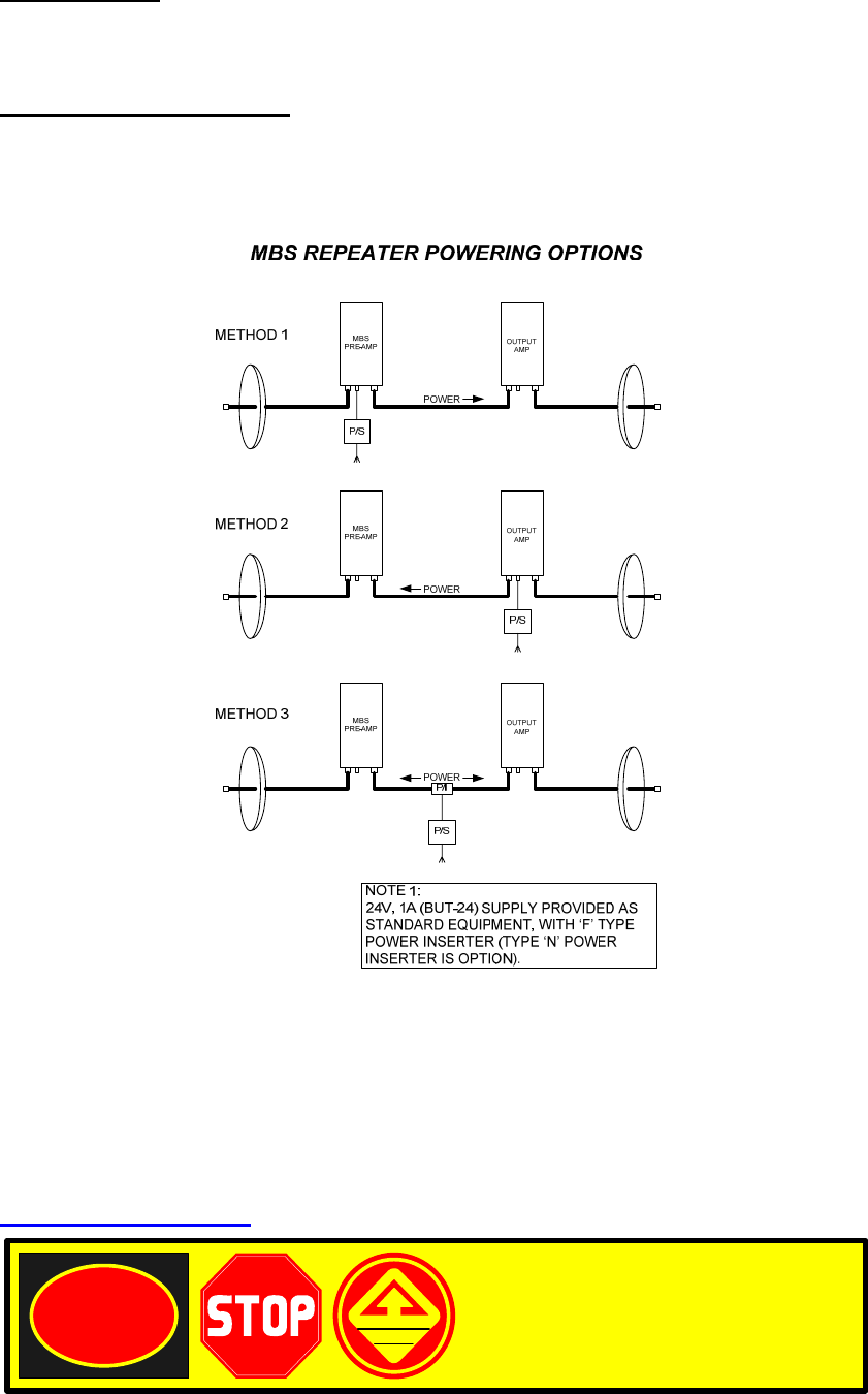
POWERING the SYSTEM
Using the diagram below, select the system powering option most suitable to the
installation.
For Further Technical Information Contact:
EMCEE Communications
1635 W. 12 Place
Tempe, AZ 85281 USA
Tel. 480-315-1661
Fax 480-315-0679
www.emceecom.com

EMCEE MBSR100MW Installation Instructions
Page 5
DANGER WATCH FOR
WIRES
You can be KILLED!
If this product comes near
electric power lines.
©2007 EMCEE Communications
MBS-BAND LOW NOISE PREAMPLIFIER-Design Specifications
EMCEE Part Number 701007
Input Frequency 2572-2614 MHz
Noise Figure 4.5 dB Typical
Gain 35 dB ±2 dB
Gain Flatness ±1.5 dB
P-out-1dB Compression Point +12/+5 dBm (single carrier)
Output 3rd Order Intercept Point +21/+14 dBm
Input VSWR 1.5:1
Output VSWR 1.5:1
Input Connector 50 Ohm, Type ‘N’ Female
Output Connector 50 Ohm, Type ‘N’ Female
DC Supply Voltage +16 to 24 VDC
Current 60ma Typical
Power Supply Connector Type ‘F’ Female or Thru Output Connector
Temperature Limits:
Operating -40°C to +50°C
Storage -50°C to +85°C
Weatherproofing Tongue and Groove Case with Full Gasket
Leak Testing Per CWT DT-2005.1
Finish Polyester Powder Coat Paint
Physical Dimensions:
Size 10.0”x 4.75“x2.0 in (254x120x50 mm)
Weight 2.5 lbs. (1.18 Kg)

EMCEE MBSR100MW Installation Instructions
Page 6
DANGER WATCH FOR
WIRES
You can be KILLED!
If this product comes near
electric power lines.
©2007 EMCEE Communications
MBS-BAND LOW-POWER REPEATER AMPLIFIER-Design Specifications
EMCEE Part Number 50800002A
Input Frequency 2572-2614 MHz
Noise Figure 1.2 dB Typical (At AGC Threshold)
Open Loop Gain 35 dB ±2 dB
Gain Flatness ±1.0 dB
Gain over Temperature ±1.0 dB
AGC Dynamic Range 20dB Typical
Output Power (6MHz Channel) +20dBm per Channel (1 Channel)
+17dBm per Channel (2 Channels)
+14dBm per Channel (4 Channels)
+11dBm per Channel (7 Channels)
Input VSWR 1.5:1
Output VSWR 1.5:1
Input Connector 50 Ohm, Type ‘N’ Female
Output Connector 50 Ohm, Type ‘N’ Female
DC Supply Voltage +16 to 28 VDC
Current 550ma Typical @ 16VDC Input
Power Supply Connector Type ‘F’ Female or Thru Input Connector
Temperature Limits: Operating -40°C to +50°C
Storage -50°C to +85°C
Weatherproofing Tongue and Groove Case with Full Gasket
Leak Testing Per CWT DT-2005.1
Finish Polyester Powder Coat Paint
Physical Dimensions: Size 10.0”x 4.75“x2.0 in (254x120x50 mm)
Weight 2.6 lbs. (1.19 Kg)

EMCEE MBSR100MW Installation Instructions
Page 7
DANGER WATCH FOR
WIRES
You can be KILLED!
If this product comes near
electric power lines.
©2007 EMCEE Communications