EMCEE Broadcast TTU1000FA UHF LPTV Transmitter User Manual TTU1000FA Mnl Cover Pg 1
EMCEE Broadcast Products UHF LPTV Transmitter TTU1000FA Mnl Cover Pg 1
UserManual.wiki
>
EMCEE Broadcast
>
TTU1000FA User Manual
>
TTU1000FA Manual
Contents
1.
TTU1000FA Manual
2.
RF Communications Model 2000 Modulator Manual
TTU1000FA Manual
Navigation menu
Upload a User Manual
Namespaces
Wiki Guide
HTML
PDF
Info
Views
User Manual
Discussion / Help
Navigation

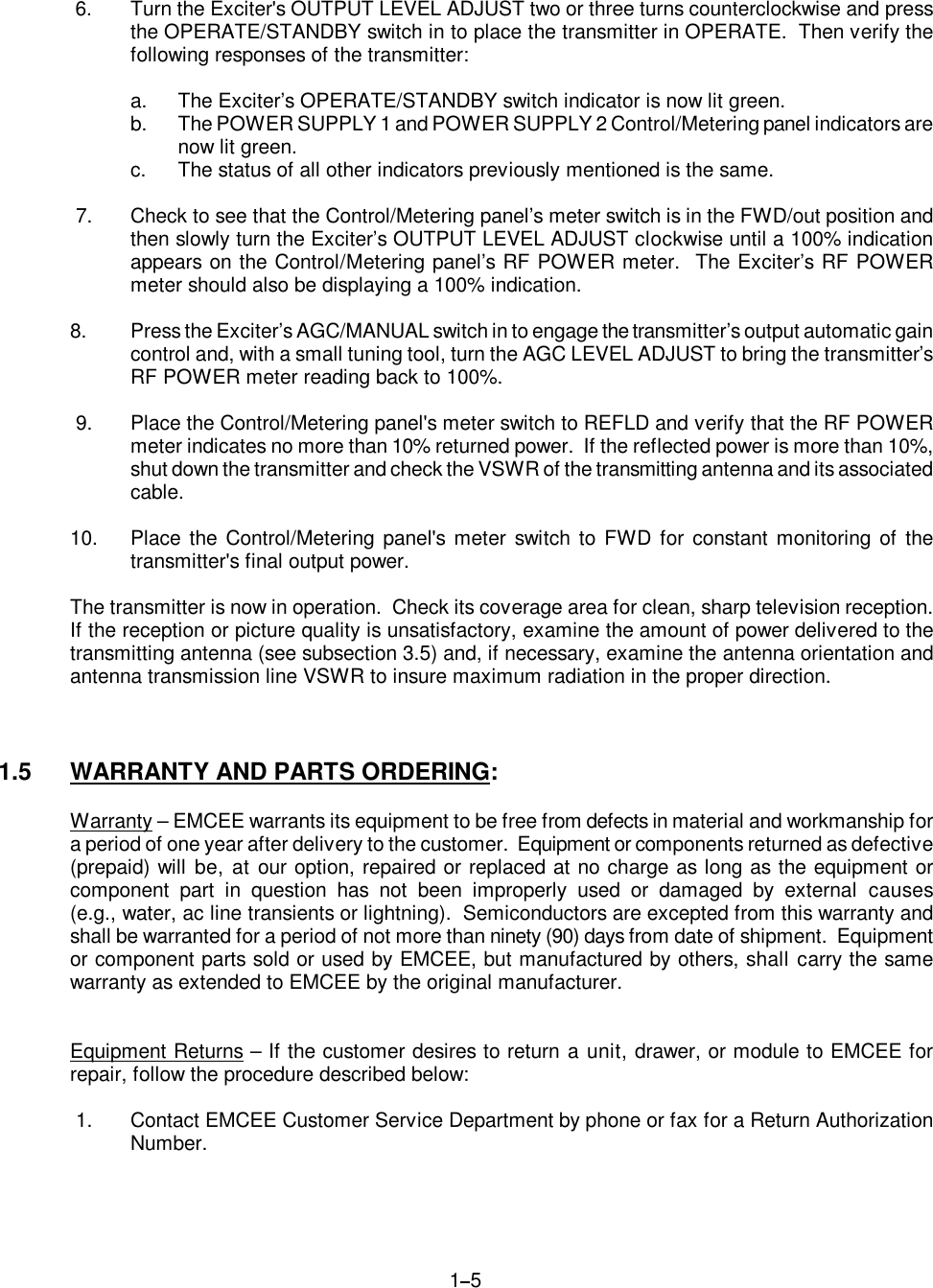

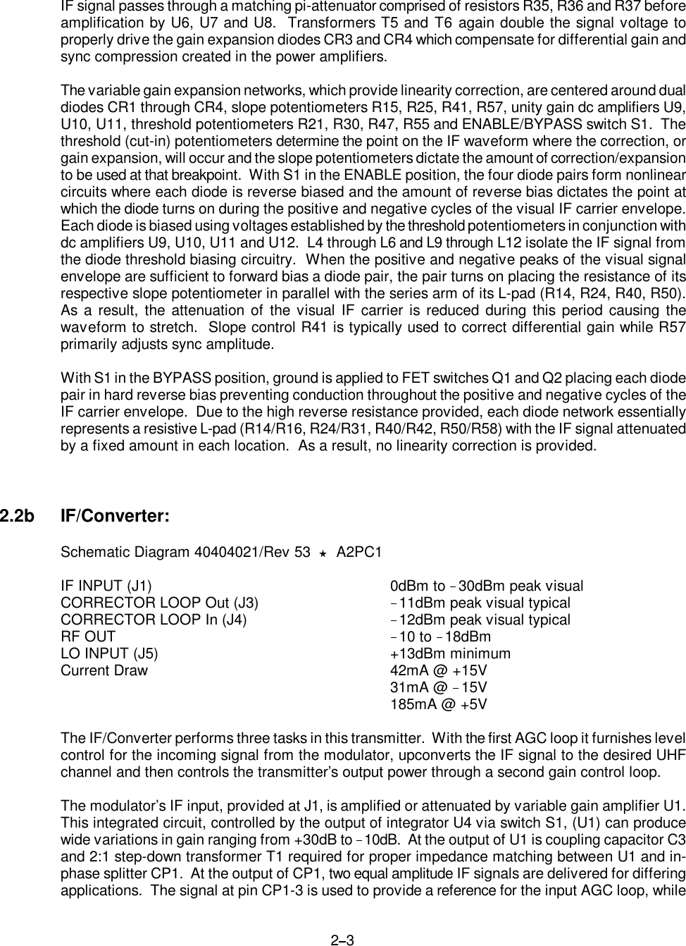
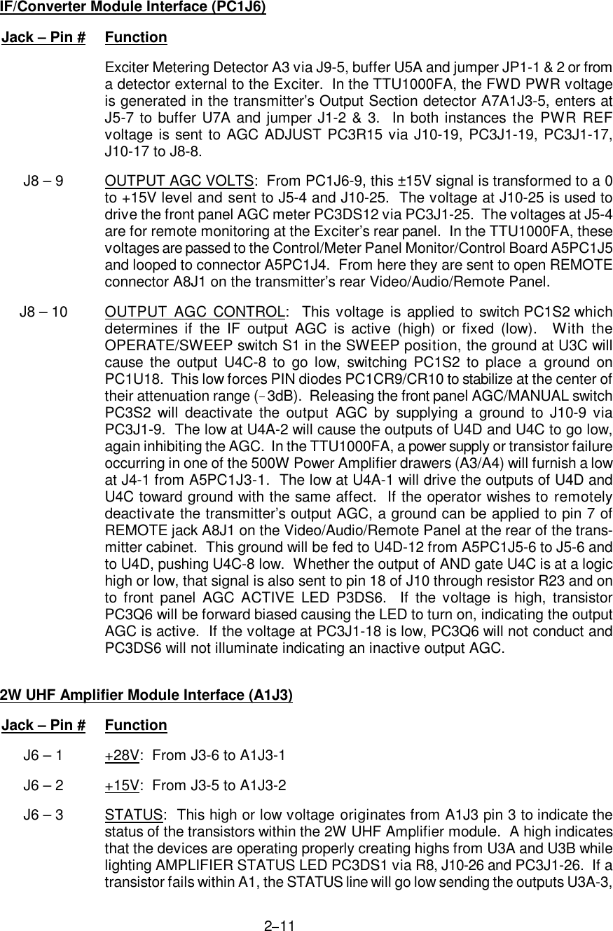
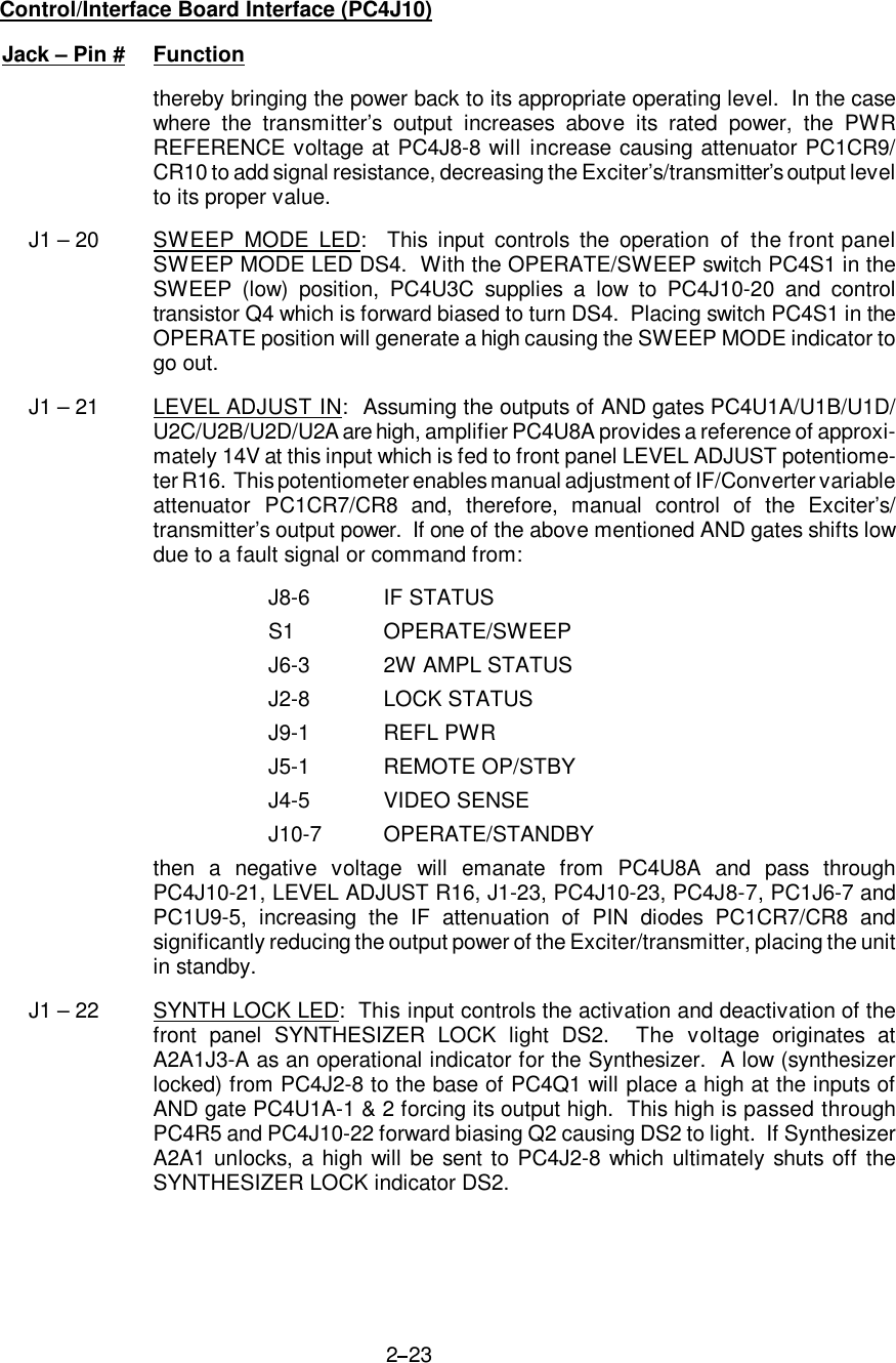
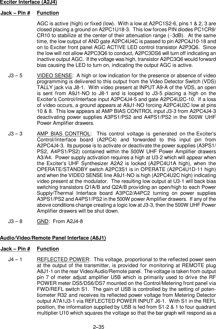
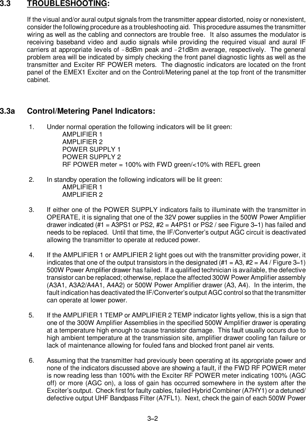
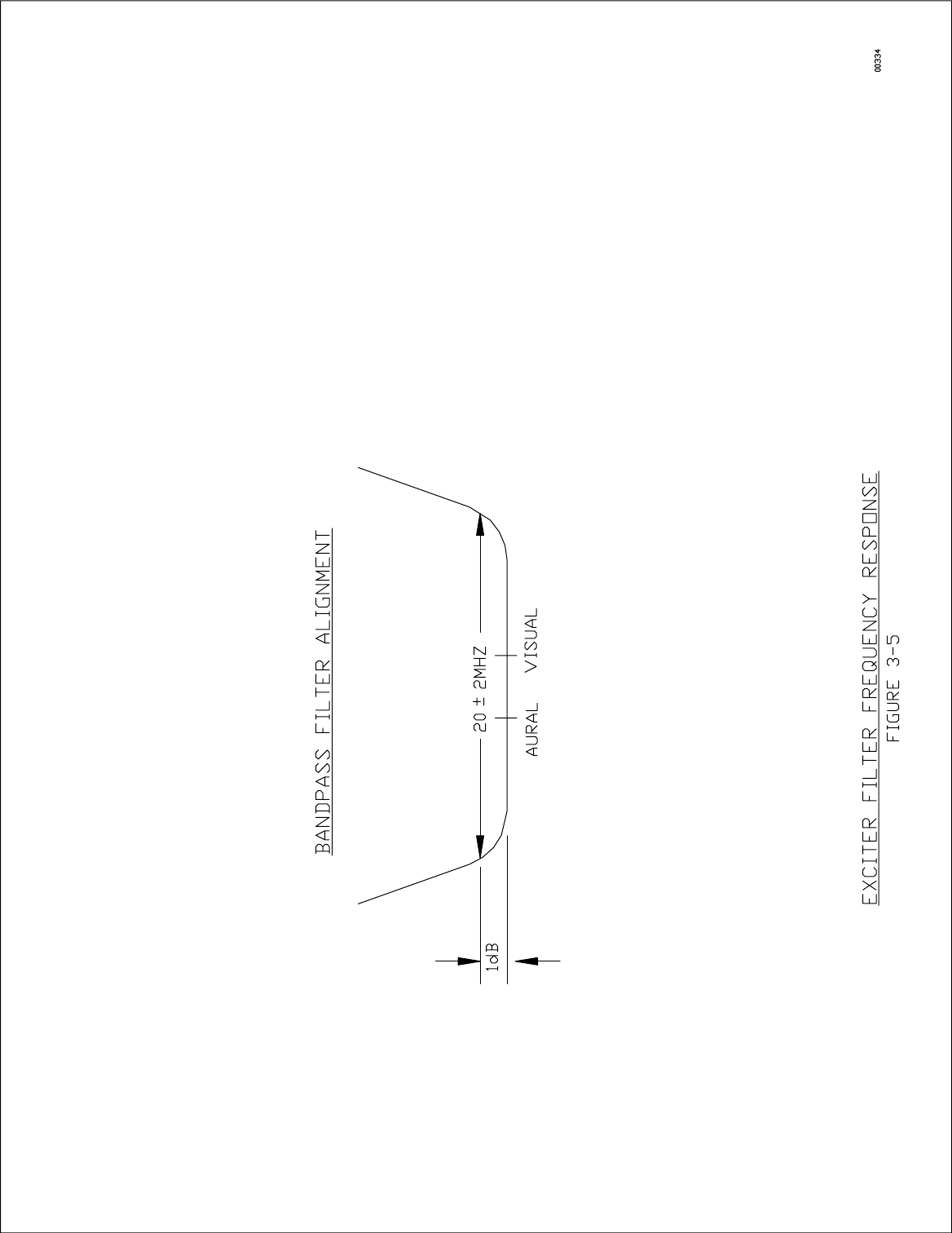
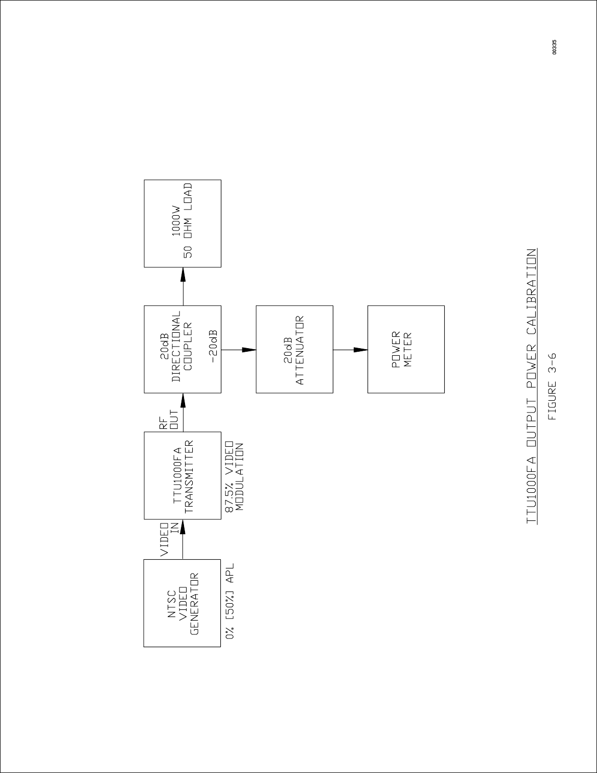
![3 83.5 OUTPUT POWER CALIBRATION:To ensure proper operation, the transmitter’s output power level and RF POWER meter calibrationshould be checked once every year. With the meter switch in the FWD position, the RF POWERmeter has been factory calibrated for 100% with the transmitter providing 1000 watts peak visualand 50 watts average aural. The following calibration procedures assume that the composite signalfrom the transmitter has the aural carrier 13dB down from the peak visual with the visual carrierhaving 87.5% video modulation and 0% (sync only) average picture level (APL). The power levelsstated in the steps below are those expected at the output of the transmitter. Therefore, whenmeasuring these power levels using the equipment shown in Figure 3 6, be sure to take intoaccount the attenuation factor provided by the 20dB directional coupler and the 20dB attenuator.Power levels at 50% APL (5 Step/Ramp/50% Flat Field) are included in brackets following thepower level at 0% APL.3.5a Forward Power: 1. Assuming the transmitter is in operation, place the Exciter’s OPERATE/STANDBY switchto STANDBY and set up the test equipment shown in Figure 3 6. 2. Using sync only video, verify that the modulator is providing 87.5% video modulation withthe aural carrier 13dB below the visual carrier. Release the Exciter AGC/MANUAL switchto the MANUAL position and the transmitter RF POWER meter switch to FWD. Place theExciter OPERATE/STANDBY switch to OPERATE. 3. Wait for the transmitter to come up to power and, using a small tuning tool, rotate theOUTPUT LEVEL ADJUST for an external power meter reading of 645W [390W]. Noticethat 1000 watts of peak visual power at 0% [50%] APL plus 50 watts of average aural powerat 13dB down equals 645W [390W] power on the external average power meter. 4. To check and adjust visual to aural ratio, replace the power meter in Figure 3 6 with aspectrum analyzer. Set the modulator’s aural carrier level adjustment for the desired visual/aural ratio. Remove the spectrum analyzer, return the power meter to the transmitter outputand recheck power. Set the OUTPUT LEVEL ADJUST again for an external power meterreading of 645W [390W]. 5. With the external power meter reading correctly, place the Control/Metering panel meterswitch to FWD and check the transmitter's RF POWER meter for a 100% indication. If thisreading is not obtained, adjust FORWARD POWER potentiometer A5PC1R32, locatedbehind the Control/Metering panel (A5) and accessible through the METER ADJUST holemarked FWD, for the correct indication. 6. Activate the transmitter’s output gain control by pushing in the Exciter AGC/MANUAL buttonand recheck the power indication on the external meter for 645 watts [390W]. If the meterreading is not correct, slowly turn the AGC LEVEL ADJUST (small tuning tool required) tocorrect the transmitter output power. The output AGC circuit has a very long time constantwhich requires the operator to wait for the transmitter power to settle after each smallmovement of the AGC LEVEL ADJUST.](https://usermanual.wiki/EMCEE-Broadcast/TTU1000FA.TTU1000FA-Manual/User-Guide-147269-Page-65.png)
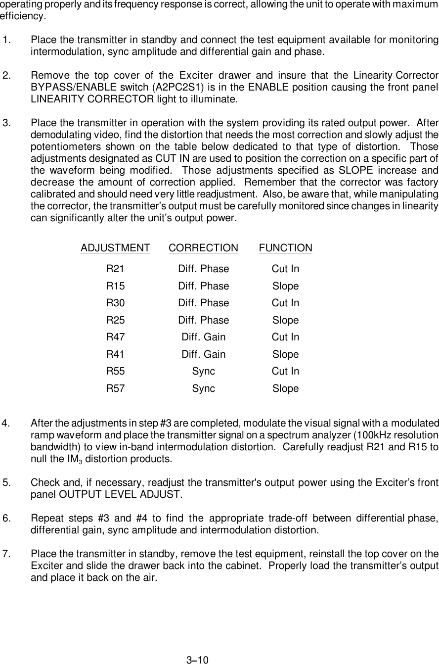
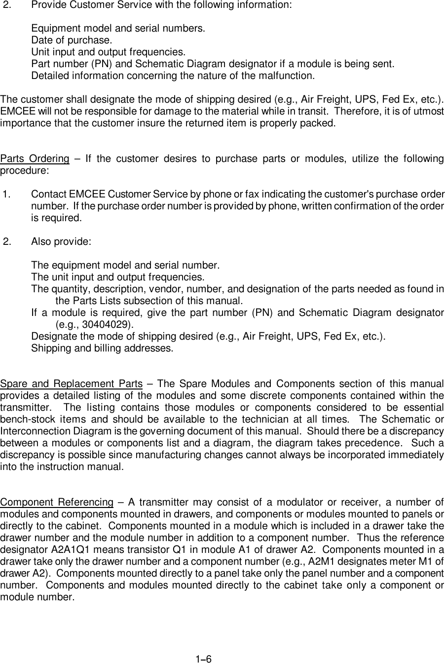
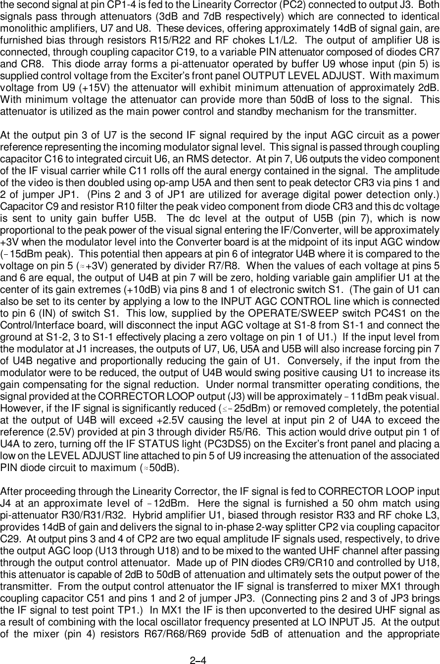
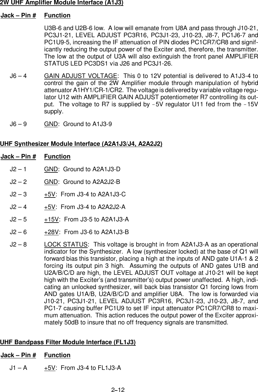
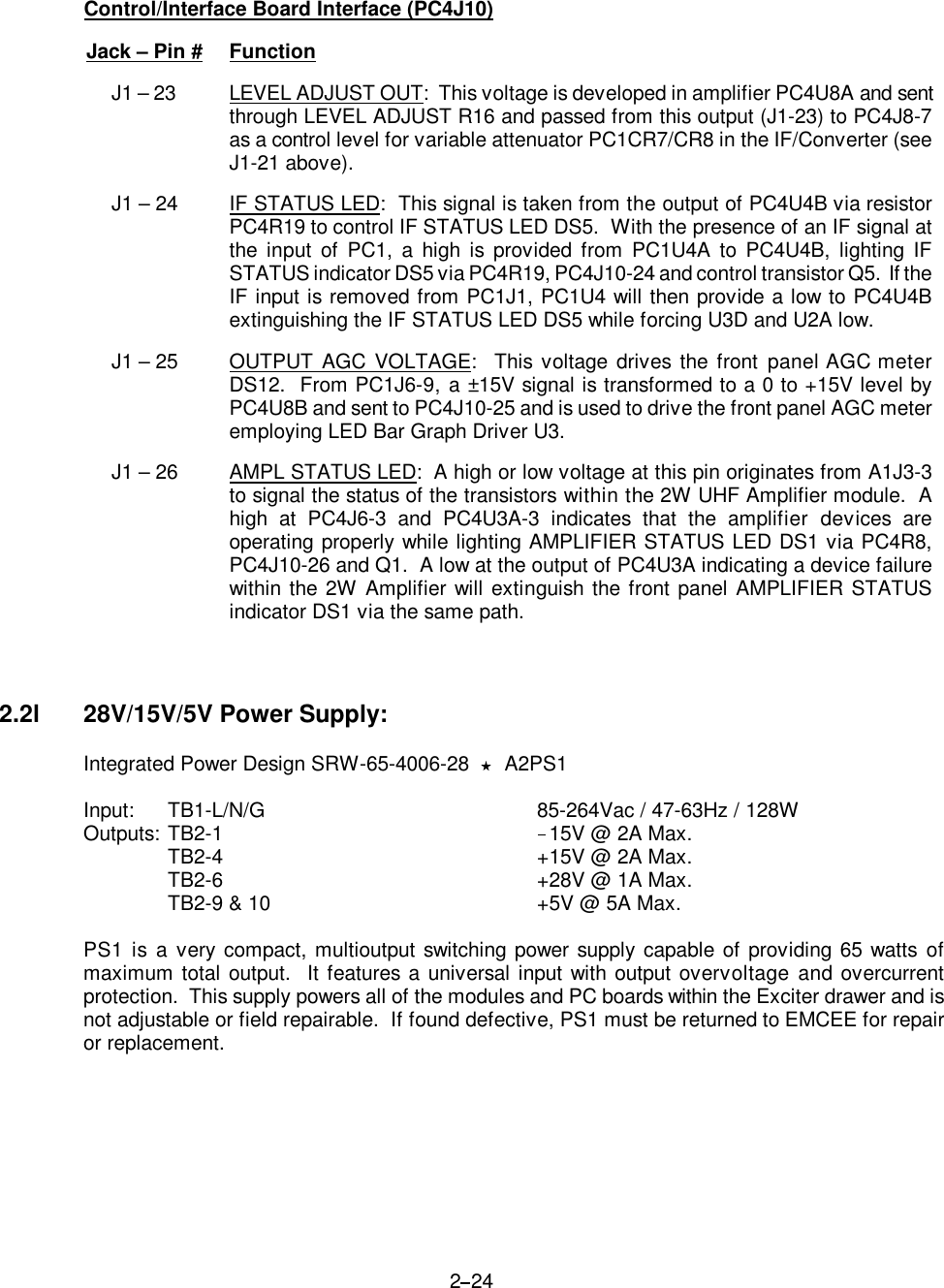
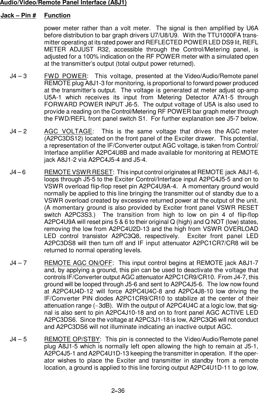
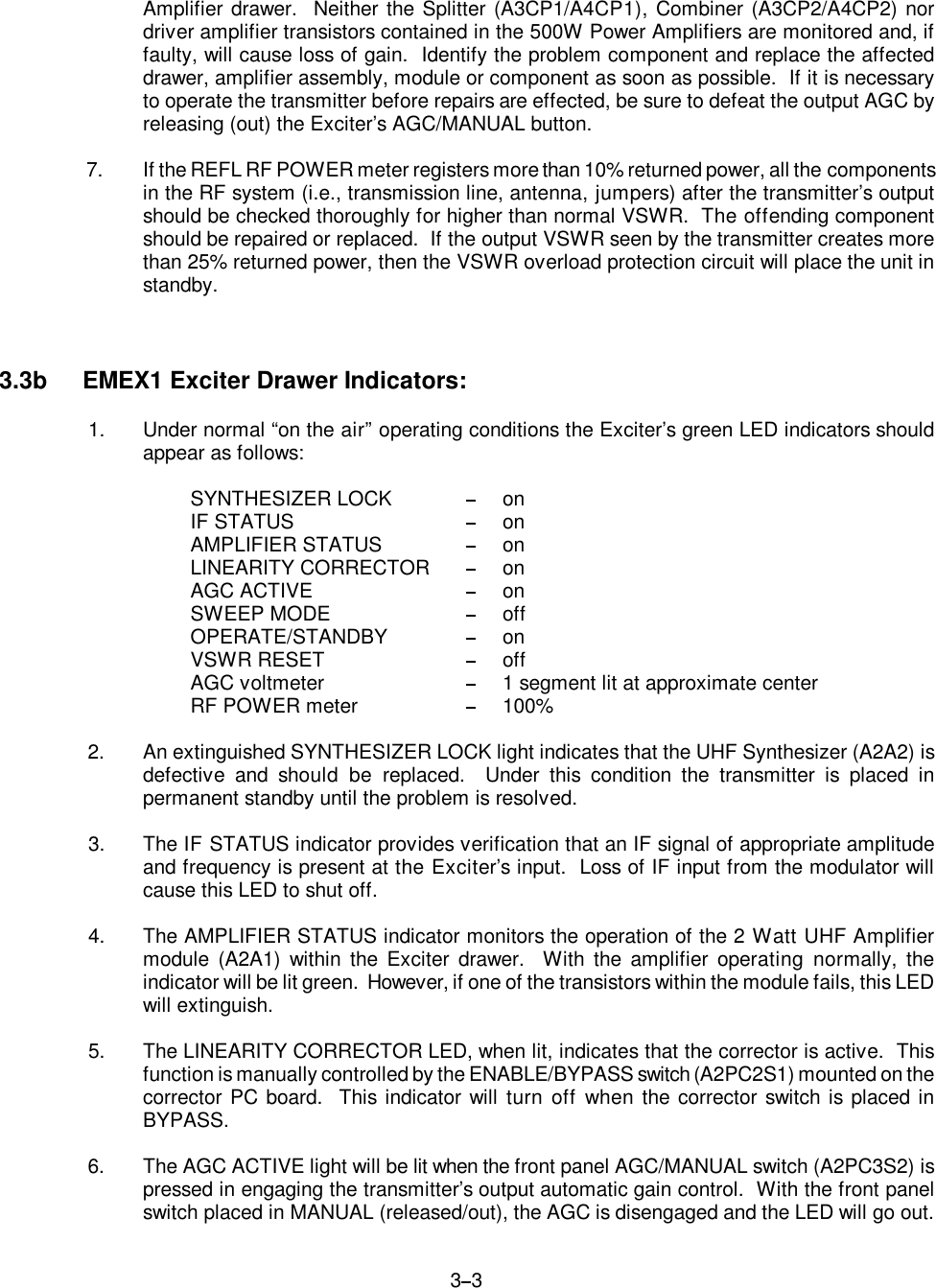
![3 93.5b Reflected Power:(OPTIONAL) 7. Carefully pull out the Exciter drawer and remove its top cover. On the Control/Interfaceboard find VSWR OVLD REF potentiometer A2PC4R12 and turn it fully counterclockwiseto disable the VSWR overload detection circuit. Place the Control/Metering panel RFPOWER meter switch to REFL. 8. Place the Exciter’s OPERATE/STANDBY switch to STANDBY and the AGC/MANUALswitch to MANUAL. Switch the INCIDENT (J3) and REFLD (J4) coupling port cables on theMetering Coupler (A7DC1). J2 (REFLD) of the Metering Detector (A5A1) should now beconnected to J3 (INCIDENT) of the Metering Coupler. This simulates an open circuit at thetransmitter's RF OUTput delivering maximum returned power to the reflected powerdetector. 9. Place the OPERATE/STANDBY switch to OPERATE and wait until the external powermeter reading of 645 watts [390W] is reached. Check the front panel RF POWER meterfor a 100% reading. If the meter is incorrect, adjust it using REFLECTED POWERpotentiometer A5PC1R32 accessible through the METER ADJUST hole marked REFL onthe Control/Metering panel (A5).10. Using the Exciter’s OUTPUT LEVEL ADJUST, decrease the transmitter's power to 25% asseen on the RF POWER meter. This power level is used for setting the trip point of theVSWR overload detection circuit. Return to the Exciter’s Control/Interface board andslowly adjust VSWR OVLD REF potentiometer A2PC4R12 clockwise until the Exciter’sVSWR RESET indicator illuminates red.11. Check the VSWR OVLD trip point by pressing the momentary VSWR RESET switch on theExciter front panel which will reactivate the transmitter. As the transmitter power rises to25%, the VSWR overload circuit should again trip. If it does not, carefully rotate the VSWROVLD REF adjust further clockwise and repeat this step to recheck the trip point.12. Place the OPERATE/STANDBY switch to STANDBY and return the metering cables to theiroriginal coupler ports (DC1J3/J4). Remove all test equipment from the transmitter, replacethe top cover on the Exciter and push the drawer back into the rack.13. After properly loading the transmitter, place the unit in operation by pressing the OPERATE/STANDBY switch in and resetting the OUTPUT LEVEL ADJUST for a 100% indication onthe RF POWER bar graph meter. Reactivate the transmitter’s output AGC as explained instep #6 above.3.6 LINEARITY CORRECTOR ADJUSTMENT:Adjustment of the transmitter linearity is accomplished using eight potentiometers on the ExciterLinearity Corrector board (A2PC1). Since the Linearity Corrector can produce unwanted distortionif adjusted incorrectly, this circuit should not be realigned unless absolutely necessary. The testequipment which should be available for readjustment of the precorrector is a spectrum analyzerwhich provides demodulated video for measurement of sync and intermodulation and/or a videomeasurement set with television demodulator for sync, differential gain, differential phase andICPM measurements. Acquire as much of this test equipment as possible since the precorrectionaccuracy will depend on equipment versatility. It is assumed that all the transmitter's circuits are](https://usermanual.wiki/EMCEE-Broadcast/TTU1000FA.TTU1000FA-Manual/User-Guide-147269-Page-66.png)