EMCEE Broadcast TUA100FA UHF LPTV Power Amplifier User Manual TUA100F Mnl Cover Pg 1
EMCEE Broadcast Products UHF LPTV Power Amplifier TUA100F Mnl Cover Pg 1
UserManual.wiki
>
EMCEE Broadcast
>
TUA100FA User Manual
TUA100FA Users Manual
Navigation menu
Upload a User Manual
Namespaces
Wiki Guide
HTML
PDF
Info
Views
User Manual
Discussion / Help
Navigation


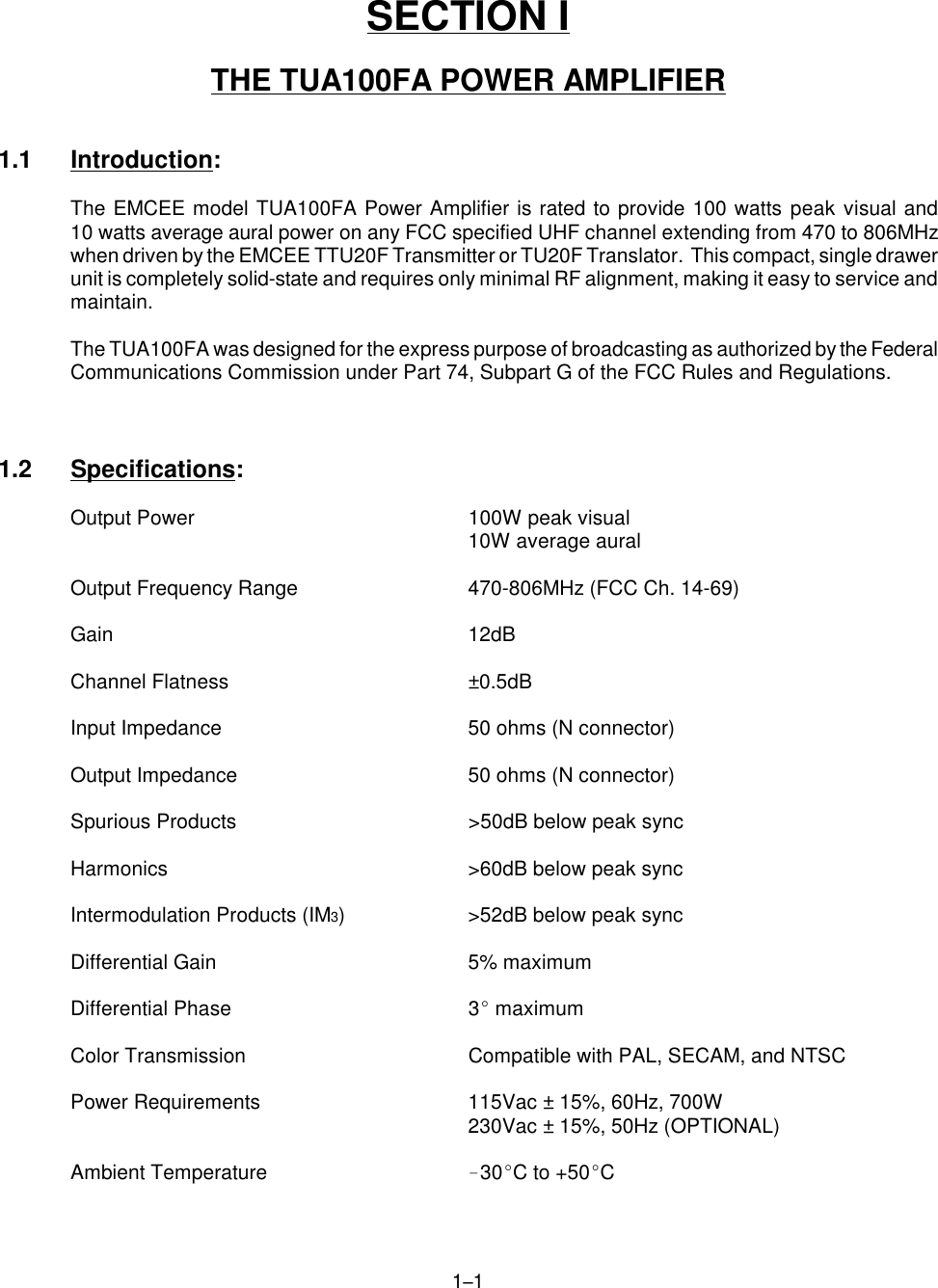
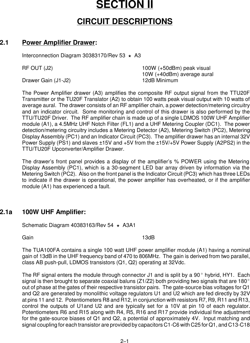
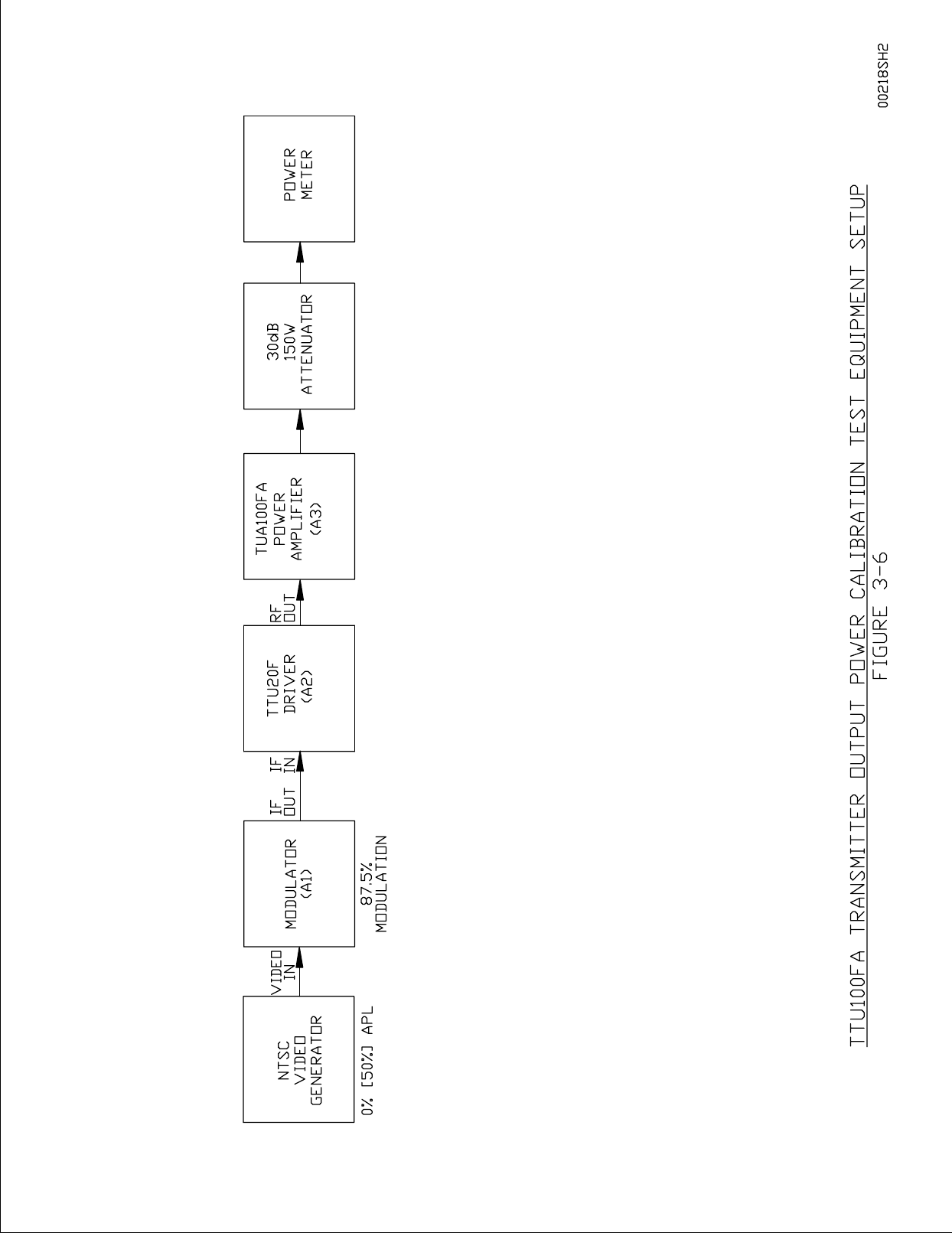
![365 2. Verify that the modulator is operating and providing 87.5% video modulation. Place the100 Watt Amplifier POWER switch to ON and make sure the Amplifier’s Meter Switch is inthe FWD position. Place the TTU20F Transmitter STANDBY switch to OPERATE. 3. To set the output power, adjust the TTU20F POWER ADJUST for an external power meterreading of 69.5W [44W]. Note that 100W peak visual at 0% [50%] APL and 87.5%modulation plus 10W average aural equals 69.5W [44W] average power. 4. To check or adjust the visual to aural carrier ratio, replace the power meter in Figure 366 witha spectrum analyzer. Adjust the aural carrier level on the modulator for the desired ratio.Remove the spectrum analyzer and return the power meter to the Transmitter’s output andreset the output power for an external power meter reading of 69.5W [44W]. 5. With the external power meter showing the correct power, place the meter switch to FWDand check the TUA100FA front panel % Power Meter for a 100% indication. If this readingis not obtained, adjust potentiometer R9 of the Metering Detector (A3) for a 100% indication.The Metering Detector is mounted on the right-hand side wall near the front of the amplifierdrawer and is accessible through the holes in the side wall. The % Power Meter on theTTU20F Transmitter/Driver will indicate less than 100% which is an appropriate reading.3.5b Reflected Power (OPTIONAL): 6. On the right side wall of the TUA100FA Power Amplifier drawer, adjust potentiometer R30of the Metering Detector fully clockwise to disable the VSWR overload detection circuit.Place the amplifier drawer meter switch to REFL. 7. Place the Transmitter/Driver OPERATE/STANDBY switch to STANDBY and the OPERATE/ALIGN switch to ALIGN. Remove and reverse the forward power (J3) and reflected power(J4) coupling port cables on the Metering Coupler (DC1). J1 and J3 of the Metering Detector(A3) should now be connected to J4 and J3 of the Metering Coupler (DC1), respectively.This simulates an open circuit at the amplifier's RF OUTput (J2) delivering maximumreturned power to the REFL port of the Metering Detector. Insert a step attenuator betweenthe modulator's IF OUTPUT and the transmitter's IF INPUT and set the step attenuator for10dB attenuation. 8. Place the Transmitter/Driver OPERATE/STANDBY switch to OPERATE. Remove theattenuation from the step attenuator for an external power meter reading of 69.5W [44W].Check the amplifier drawer's front panel REFL meter for a 100% [70%] reading. Ifnecessary, adjust potentiometer R27 of the amplifier Metering Detector for the properreading. R7 is accessible through the right-hand side wall of the drawer. 9. Decrease the transmitter's power to 50% by increasing the step attenuator 3dB for anexternal power meter reading of 34.75W [22W]. This power level is used for setting the trippoint of the VSWR overload detection circuit. Adjust R30 of the amplifier’s Metering Detectorslowly counterclockwise until the front panel VSWR OVLD indicator illuminates red and theTransmitter/Driver is placed in standby.](https://usermanual.wiki/EMCEE-Broadcast/TUA100FA/User-Guide-97058-Page-21.png)
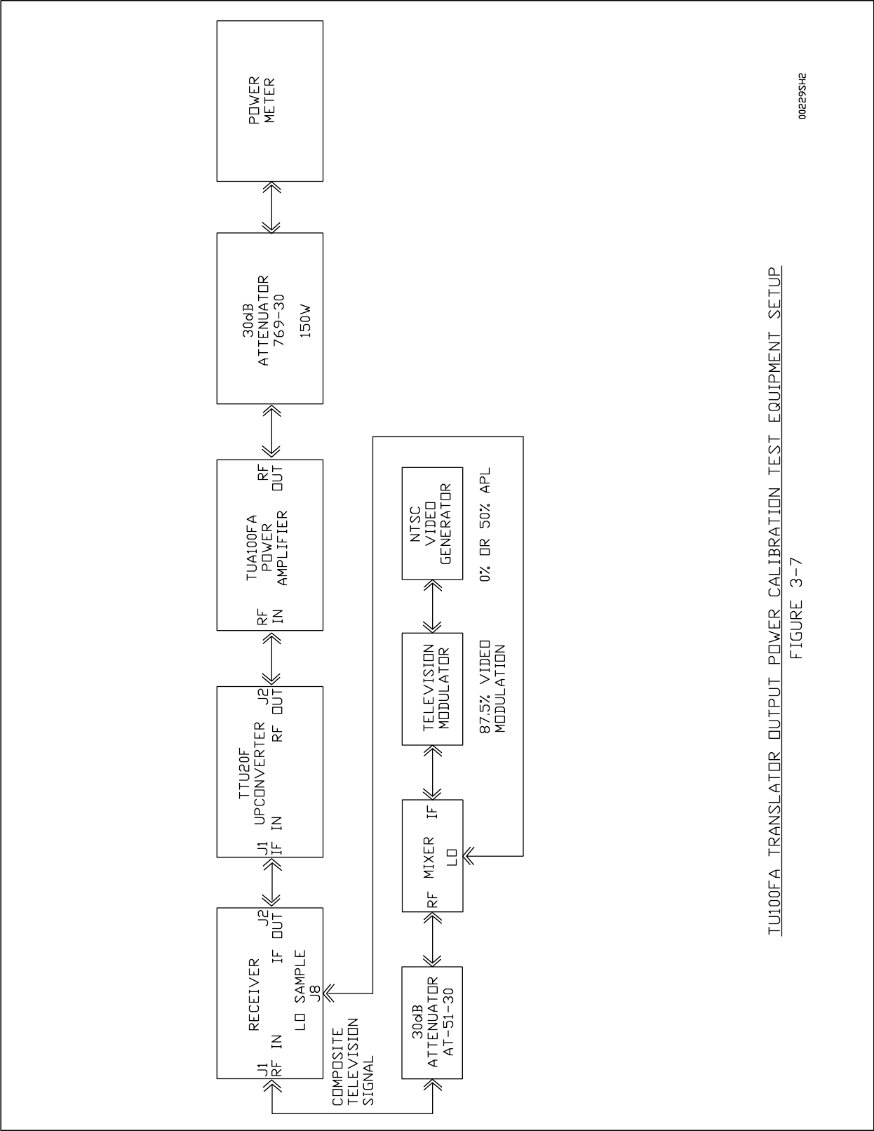
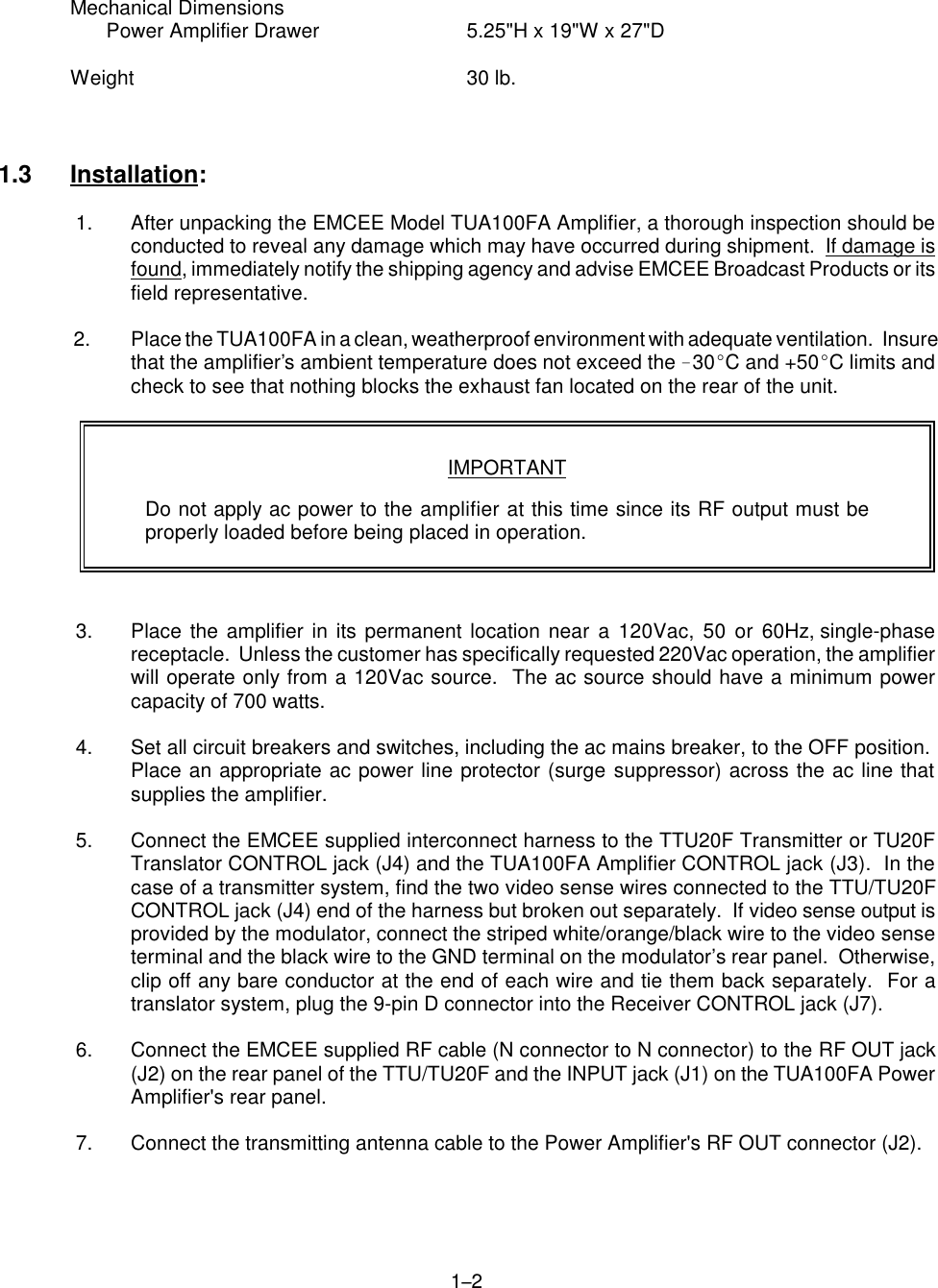
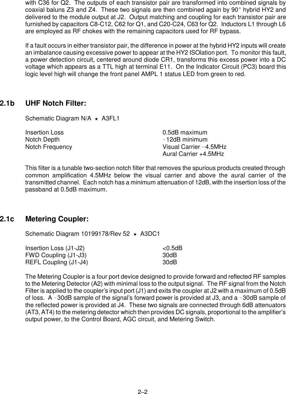
![36610. Check the VSWR OVLD trip point by setting the step attenuator for an additional 1dB ofattenuation. Press the momentary VSWR RESET switch to reset the transmitter andremove the additional 1dB of attenuation from the step attenuator. The VSWR OVLD circuitshould again trip. If it does not, repeat this section beginning at step #6.11. Place the OPERATE/STANDBY switch to STANDBY. Return the Metering Coupler cablesto their original ports, J3 and J4. Reinstall the top cover, slide the drawer back into thecabinet and secure it properly. Properly load the transmitter and place the Driver OPERATE/ALIGN and OPERATE/STANDBY switches to OPERATE.3.6 TU100FA Translator Power Calibration:To ensure proper transmission, the output power level and % Power Meter calibration of thetranslator should be checked once every year. With the meter switch in the FWD position, theTUA100FA Amplifier % Power Meter has been factory calibrated for 100% with the translatorproviding 100 watts peak visual and 10 watts average aural. The following calibration procedureassumes that the composite signal received by the translator has the aural carrier 10dB down fromthe visual with the visual carrier having 87.5% video modulation and 0% average picture level (APL).In the following steps, the power levels stated are those expected at the output of the translator.Therefore, when measuring these power levels as shown in Figure 367, be sure to take into accountthe 30dB factor provided by the attenuator. Power levels at 50% APL (stair steps) are included inbrackets following the power levels at 0% APL (SYNC only).This procedure also assumes the setup in Figure 367 is being used and that the output of thereceiver drawer has been correctly calibrated. If the received broadcast channel frequency is in theVHF band (Ch.2-13), the mixer can be deleted from the test setup and a VHF agile modulator seton the correct channel may be connected directly to the RF INput (J1) of the Receiver drawerthrough an attenuator.3.6a Forward Power: 1. With the TU20F Translator drawer in STANDBY and the TUA100FA Amplifier POWER ONcircuit breaker switch open (down), set up the test equipment as shown in Figure 367. 2. Verify that the modulator is providing 87.5% video modulation with the aural 10dB below thevisual and that the input signal is at the correct frequency (Receiver’s input channel) and atan amplitude between !40dBm to !47dBm. Place the TUA100FA 100 Watt Power Amplifierinto operation and make sure the Meter Switch is displaying FWD power. Turn the TU20FTransmitter/Driver ON and place both the OPERATE/STANDBY and OPERATE/ALIGNswitches to OPERATE. 3. To set the output power, adjust the Driver’s POWER ADJUST control for an external powermeter reading of 69.5W [44W]. Note that 100W peak visual at 0% [50%] APL and 87.5%modulation plus 10W average aural equals 69.5W [44W].](https://usermanual.wiki/EMCEE-Broadcast/TUA100FA/User-Guide-97058-Page-22.png)
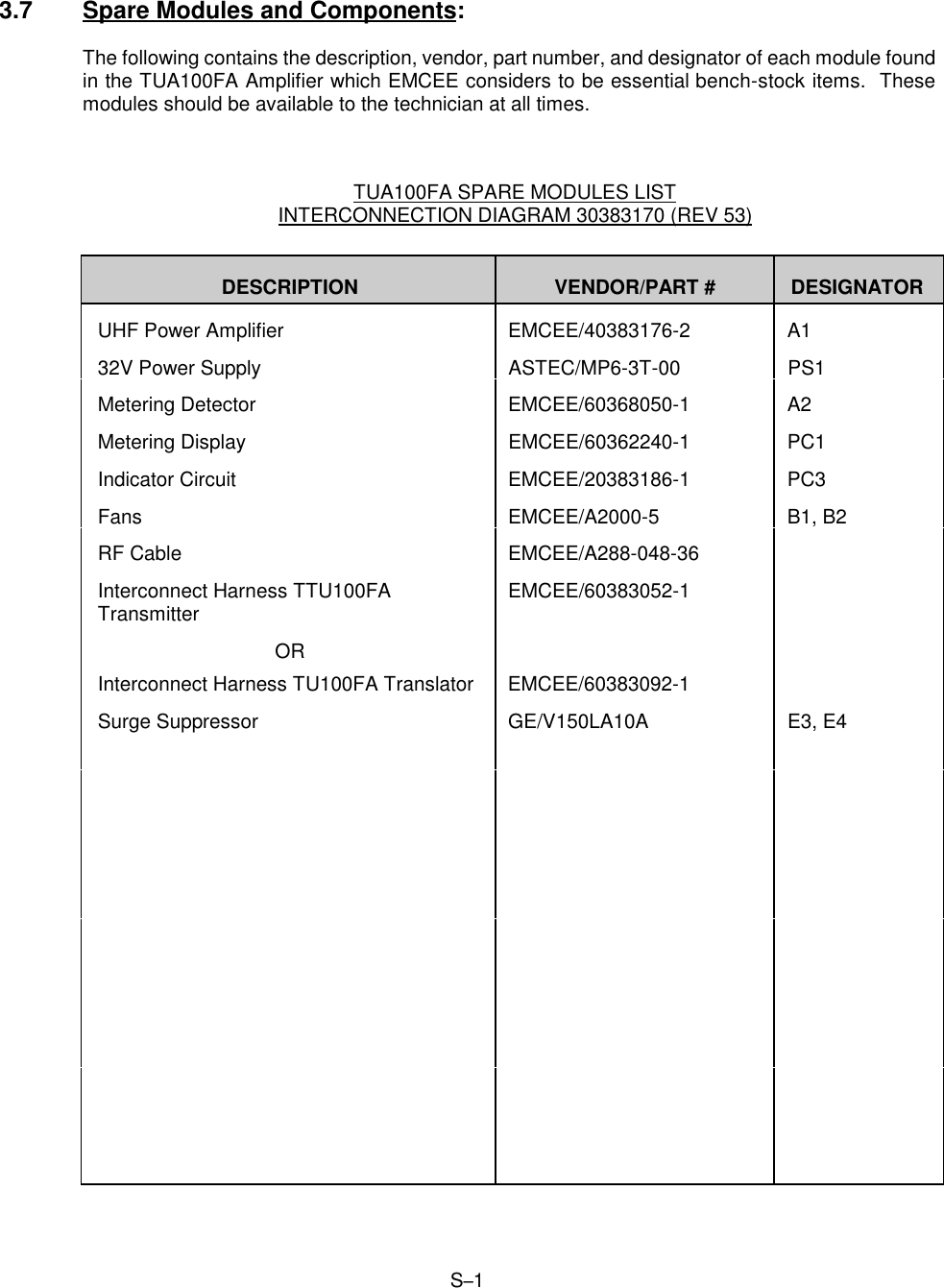
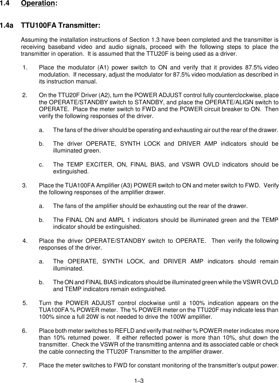
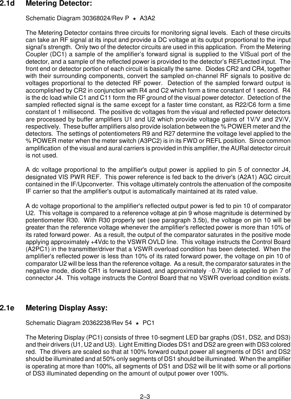
![367 4. With the external power meter reading the correct output power, place the meter switch toFWD and check the TUA100FA Amplifier front panel % Power Meter for a 100% indication.If this reading is not obtained, adjust potentiometer R9 of the Metering Detector (A3) for a100% indication. The Metering Detector is mounted on the right-hand side wall near the frontof the amplifier drawer and is accessible through the holes in the side wall. The % PowerMeter on the TU20F Driver will read less than 100% which is an appropriate indication.3.6b Reflected Power (OPTIONAL): 5. On the right side wall of the 100W Power Amplifier drawer, adjust potentiometer R30 of theMetering Detector fully clockwise to disable the VSWR overload detection circuit and placethe meter switch to REFL. 6. Place the Transmitter/Driver OPERATE/STANDBY switch to STANDBY and the OPERATE/ALIGN switch to ALIGN. In the amplifier drawer remove and reverse the forward power (J3)and reflected power (J4) coupling port cables on the Metering Coupler (DC1). J1 and J3 ofthe Metering Detector (A3) should now be connected to J4 and J3 of the Metering Coupler(DC1), respectively. This simulates an open circuit at the amplifier’s RF OUTput (J2)delivering maximum returned power to the REFL port of the Metering Detector. Insert a stepattenuator between the Receiver’s IF OUTPUT and the Transmitter’s IF INPUT and set thestep attenuator for 10dB attenuation. 7. Place the Transmitter’s OPERATE/STANDBY switch to OPERATE. Remove attenuationfrom the stepper for an external power meter reading of 69.5W [44W]. Check the amplifierdrawer's front panel meter for a 100% [70%] reading and, if necessary, adjust potentiometerR27 of the Amplifier’s Metering Detector for the proper reading. R27 is accessible throughthe right-hand side wall of the drawer. 8. Decrease the translator's power to 50% by increasing the step attenuator 3dB for an externalpower meter reading of 34.75W [22W]. This power level is used for setting the trip point ofthe VSWR overload detection circuit. Adjust R30 of the Amplifier’s Metering Detector slowlycounterclockwise until the front panel VSWR OVLD indicator illuminates red and theTranslator/Driver drops into standby. 9. Check the VSWR OVLD trip point by increasing the step attenuator an additional 1dB. Pressthe momentary VSWR RESET switch to reactivate the Translator and remove the additional1dB of attenuation from the attenuator. The VSWR OVLD circuit should again trip. If it doesnot, repeat this section beginning at step #5.10. Place the OPERATE/STANDBY switch to STANDBY. Return the Amplifier Metering Couplercables to their original ports, J3 and J4. Reinstall the top cover, slide the drawer back intothe cabinet and secure it properly. Properly load the Translator and place both theOPERATE/ALIGN and the OPERATE/STANDBY switches to OPERATE.](https://usermanual.wiki/EMCEE-Broadcast/TUA100FA/User-Guide-97058-Page-23.png)