EMI Air Handler (indoor Blower&evap) Manual L0612529
User Manual: EMI EMI Air Handler (indoor blower&evap) Manual EMI Air Handler (indoor blower&evap) Owner's Manual, EMI Air Handler (indoor blower&evap) installation guides
Open the PDF directly: View PDF ![]() .
.
Page Count: 40
Enviromaster International LLC
5780 Success Dr.
Rome, NY 13440
www.enviromaster.com
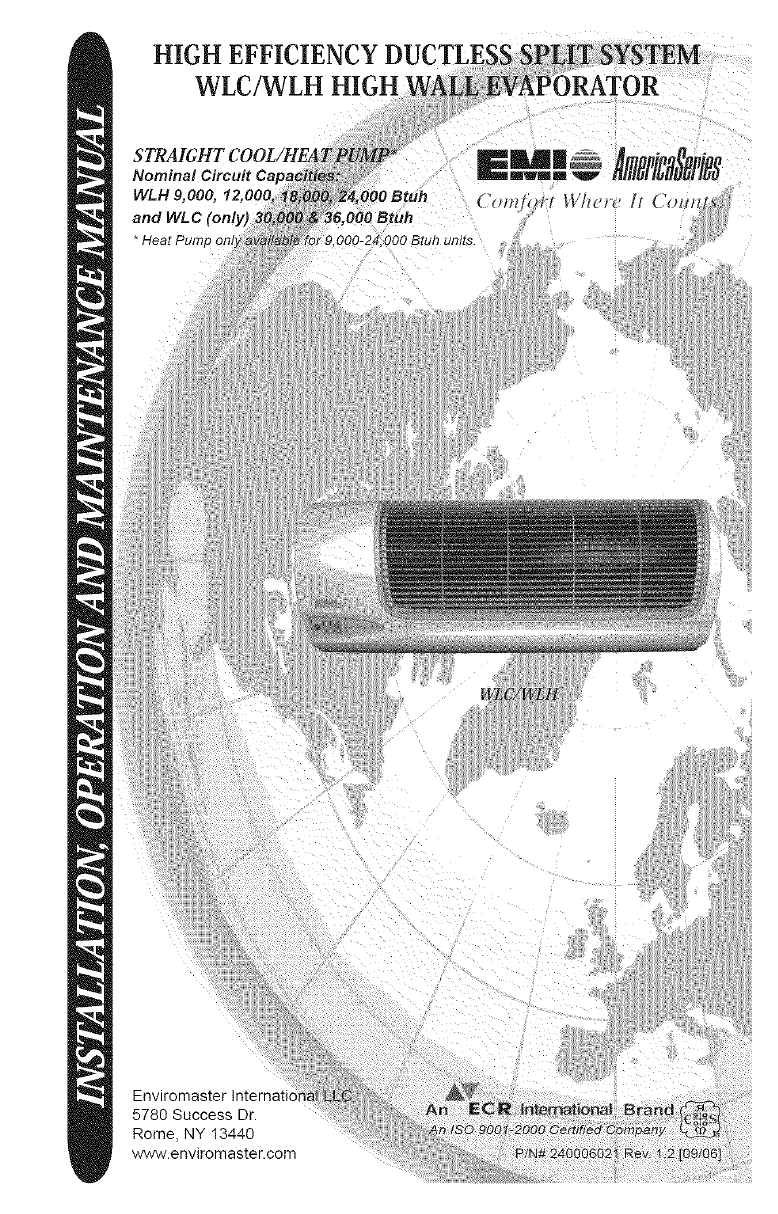
INSTALLATION,OPERATIONANDMAINTENANCEMANUAL
P/N240006021,Rev.1.2[09/06]
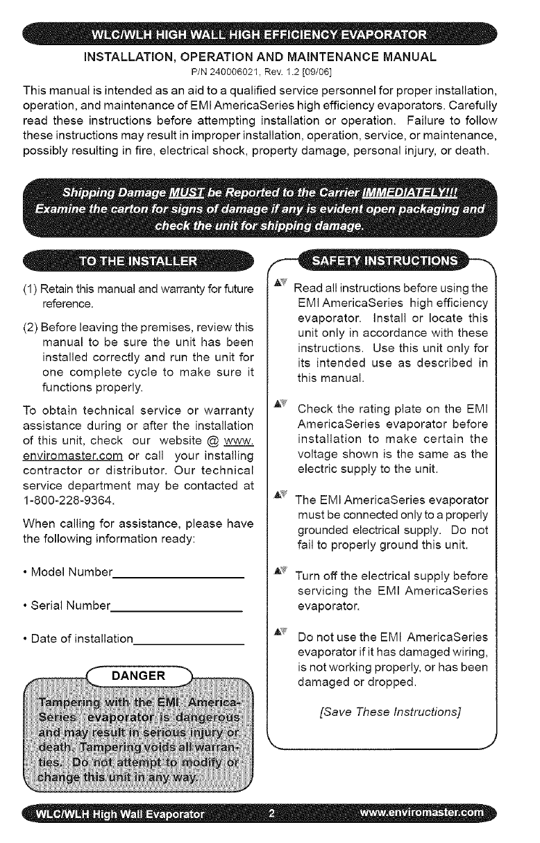
Thismanualisintendedasanaidtoaqualifiedservicepersonnelforproperinstallation,
operation,andmaintenanceofEMIAmericaSerieshighefficiencyevaporators. Carefully
read these instructions before attempting installation or operation. Failure to follow
these instructions may result in improper installation, operation, service, or maintenance,
possibly resulting in fire, electrical shock, property damage, personal injury, or death.
(1) Retain this manual and warranty for future
reference.
(2) Before leaving the premises, review this
manual to be sure the unit has been
installed correctly and run the unit for
one complete cycle to make sure it
functions properly.
To obtain technical service or warranty
assistance during or after the installation
of this unit, check our website @ www.
enviromaster.com or call your installing
contractor or distributor. Our technical
service department may be contacted at
1-800-228-9364.
When calling for assistance, please have
the following information ready:
• Model Number
• Serial Number
• Date of installation
DANGER
'_' Read all instructions before using the
EMI AmericaSeries high efficiency
evaporator. Install or locate this
unit only in accordance with these
instructions. Use this unit only for
its intended use as described in
this manual.
Check the rating plate on the EMI
AmericaSeries evaporator before
installation to make certain the
voltage shown is the same as the
electric supply to the unit.
The EMI AmericaSeries evaporator
must be connected only to a properly
grounded electrical supply. Do not
fail to properly ground this unit.
Turn off the electrical supply before
servicing the EMI AmericaSeries
evaporator.
Do not use the EMI AmericaSeries
evaporator if it has damaged wiring,
is not working properly, or has been
damaged or dropped.
[Save These Instructions]
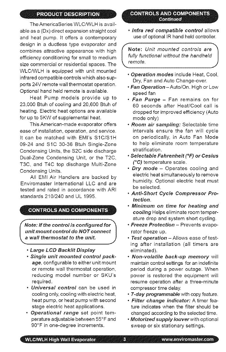
The AmericaSeries WLC/WLH is avail-
able as a (Dx) direct expansion straight cool
and heat pump. It offers a contemporary
design in a ductless type evaporator and
combines attractive appearance with high
efficiency conditioning for small to medium
size commercial or residential spaces. The
WLC/WLH is equipped with unit mounted
infrared compatible controls which also sup-
ports 24V remote wall thermostat operation.
Optional hand held remote is available.
Heat Pump models provide up to
23,000 Btuh of cooling and 20,600 Btuh of
heating. Electric heat options are available
for up to 5KW of supplemental heat.
This American-made evaporator offers
ease of installation, operation, and service.
It can be matched with EMl's $1C/81H
09-24 and S1C 30-36 Btuh Single-Zone
Condensing Units, the $2C side discharge
Dual-Zone Condensing Unit, or the T2C,
T3C, and T4C top discharge Multi-Zone
Condensing Units.
All EMI Air Handlers are backed by
Enviromaster International LLC and are
tested and rated in accordance with ARI
standards 210/240 and UL 1995.
ote: If the control is configured for_
nit mount control do NOT connect I
wall thermostat to the unit. .J
•Large LCD Backlit Display
•Single unit mounted control pack-
age, configurable to either unit mount
or remote wall thermostat operation,
reducing model number or 8KU's
required.
•Universal control can be used in
cooling only, cooling with electric heat,
heat pump, or heat pump with second
stage electric heat applications.
•Operational range set point tem-
perature adjustable between 55°F and
90°F in one-degree increments.
•Infra red compatible control allows
use of optional IR hand held controller.
!uOte: Unit mounted controls are_
Ily functional without the handheld|
emote. J
•Operation modes include Heat, Cool,
Dry, Fan and Auto Change-over.
•Fan Operation-AutolOn. High or Low
speed fan
•Fan Purge - Fan remains on for
60 seconds after Heat/Cool call is
dropped for improved efficiency (Auto
mode only)
•Room air sampling: Selectable time
intervals ensure the fan will cycle
on periodically, in Auto Fan Mode
to help eliminate room temperature
stratification.
•Selectable Fahrenheit (°F) or Cesius
(°C) temperature scale.
•Dry mode - Operates cooling and
electric heat simultaneously to remove
humidity. Optional electric heat must
be selected.
•Anti-Short Cycle Compressor Pro-
tection.
•Minimum on time for heating and
cooling Helps eliminate room temper-
ature drop and system short cycling.
•Freeze Protection - Prevents evapo-
rator freeze up.
•Test operation - Allows ease of test-
ing after installation (all timers are
eliminated).
•Non-volatile back-up memory will
maintain control settings for an indefinite
period during a power outage. When
power is restored the equipment will
resume operation after a three-minute
compressor time delay.
• 7-day programmable with copy feature.
•Filter change indicator: A timer fea-
ture indicates when the filter should be
changed according to the selected time.
•Motorized supply Iouverwith optional
sweep or six stationary settings.
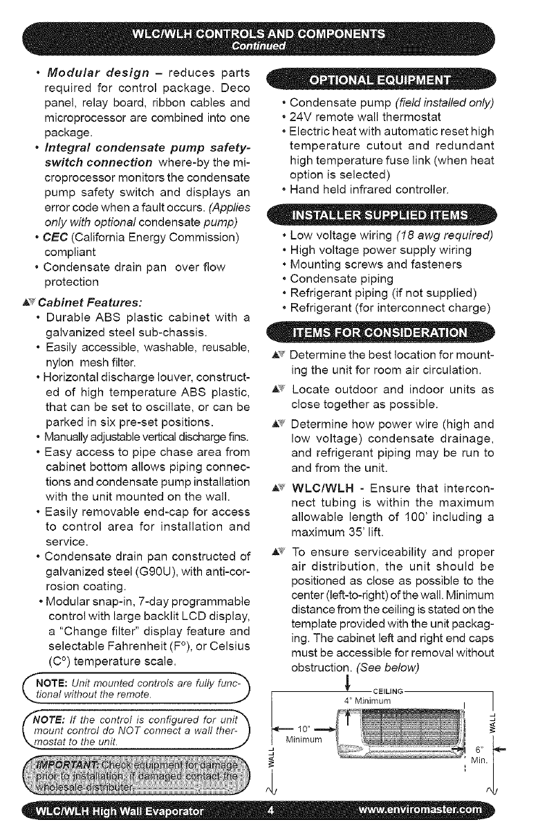
•Modular design - reduces parts
required for control package. Deco
panel, relay board, ribbon cables and
microprocessor are combined into one
package.
•Integral condensate pump safety-
switch connection where-by the mi-
croprocessor monitors the condensate
pump safety switch and displays an
error code when a fault occurs. (Applies
only with optional condensate pump)
•CEC (California Energy Commission)
compliant
• Condensate drain pan over flow
protection
A_ Cabinet Features:
• Durable ABS plastic cabinet with a
galvanized steel sub-chassis.
• Easily accessible, washable, reusable,
nylon mesh filter.
• Horizontal discharge louver, construct-
ed of high temperature ABS plastic,
that can be set to oscillate, or can be
parked in six pre-set positions.
• Manually adjustable vertical discharge fins.
• Easy access to pipe chase area from
cabinet bottom allows piping connec-
tions and condensate pump installation
with the unit mounted on the wall.
• Easily removable end-cap for access
to control area for installation and
service.
• Condensate drain pan constructed of
galvanized steel (Gg0U), with anti-cor-
rosion coating.
• Modular snap-in, 7-day programmable
control with large backlit LCD display,
a "Change filter" display feature and
selectable Fahrenheit (F°), or Celsius
(C °) temperature scale.
NOTE: Unit mounted controls are fully fun_-_
OTE: If the control is configured for unit_
ount control do NOT connect a wall ther- )
£statto theun!t_ _/
• Condensate pump (field installed only)
• 24V remote wall thermostat
• Electric heat with automatic reset high
temperature cutout and redundant
high temperature fuse link (when heat
option is selected)
• Hand held infrared controller.
•Low voltage wiring (18 awg required)
• High voltage power supply wiring
• Mounting screws and fasteners
• Condensate piping
• Refrigerant piping (if not supplied)
•Refrigerant (for interconnect charge)
O" ® I " _ •
• ._ Determine the best location for mount-
ing the unit for room air circulation.
_ Locate outdoor and indoor units as
close together as possible.
,t_" Determine how power wire (high and
low voltage) condensate drainage,
and refrigerant piping may be run to
and from the unit.
,_ WLC/WLH - Ensure that intercon-
nect tubing is within the maximum
allowable length of 100' including a
maximum 35' lift.
,_'¢ To ensure serviceability and proper
air distribution, the unit should be
positioned as close as possible to the
center (left-to-right) of the wall. Minimum
distance from the ceiling is stated on the
template provided with the unit packag-
ing. The cabinet left and right end caps
must be accessible for removal without
obstruction. (See below)
CEILING
4" Minimum
Minimum
]
d
J
The WLC/WLH must be mounted
plumb and level to a vertical surface to
prevent unit vibration and/or unwanted
noise. It is recommended that the unit
be mounted directly to a smooth surface
such as Sheetrock ® wallboard or similar
material. If mounting to a masonry block
wall, there should be a smooth barrier
between the unit and the masonry block
surface to absorb any potential vibration
and prevent the formation of condensation
on the wall.
"NOTE: If excessive noise or vibration is ex-_
perienced from a unit mounted toa masonry I
block wall, check to ensure the unit is plumb I
and level. If noise or vibration persists, con- I
_act the Wholesale Distributor. ,._
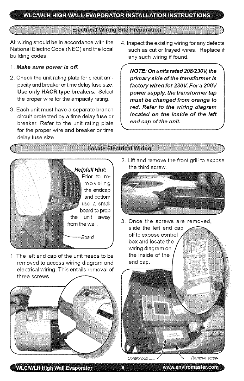
1. After determining the best location for 5. Secure the bracket to the wall with the
the unit, use the cardboard template appropriate screws (for wood) or an-
provided in the packaging, chors (for masonry). Ensure the bracket
is mounted in a manner that will support
the weight of the unit.
NoOte: The wall hanging bracket slot is NOT_
cared in the center of the unit. J
2. Mark where the piping, electrical wiring
and condensate drain should penetrate
the wall.
3. Determine the appropriate hole size and
cut through the wall. slot
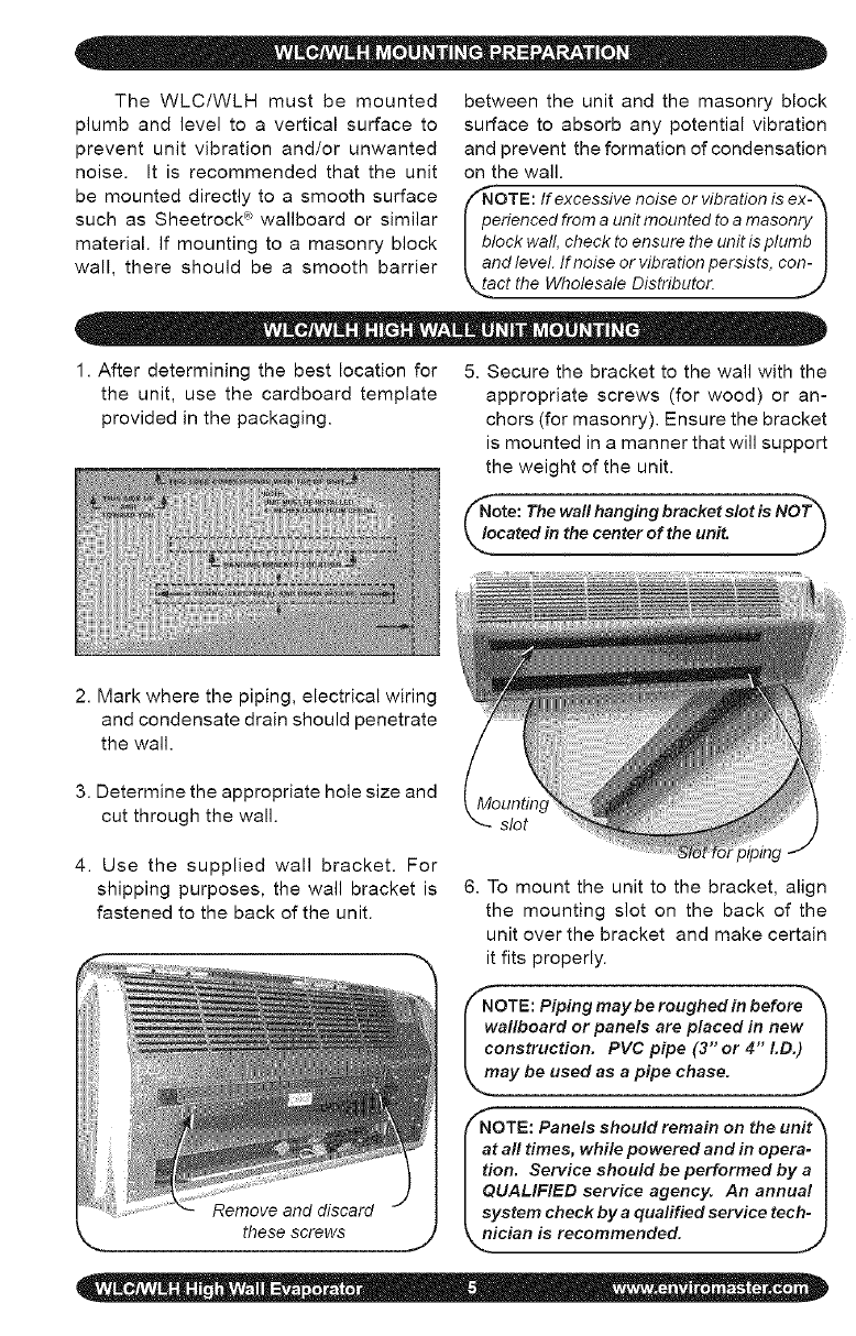
4. Use the supplied wall bracket. For
shipping purposes, the wall bracket is
fastened to the back of the unit.
6. To mount the unit to the bracket, align
the mounting slot on the back of the
unit over the bracket and make certain
it fits properly.
(_NOTE: Piping may be roughed in before'_
wallboard or panels are placed in new I
construction. PVC pipe (3 or 4 LD.) I
_, may be used as a pipe chase. J
_NOTE: Panels should remain on the unit_
at all times, while powered and in opera-
tion. Service should be performed by a
QUALIFIED service agency. An annual
system check by aqualified service tech-
_nician is recommended.
lJ
these screws
F
All wiring should be in accordance with the
National Electric Code (NEC) and the local
building codes.
1. Make sure power is off.
2. Check the unit rating plate for circuit am-
pacity and breaker or time delay fuse size.
Use only HACR type breakers. Select
the proper wire for the ampacity rating.
3. Each unit must have a separate branch
circuit protected by a time delay fuse or
breaker. Refer to the unit rating plate
for the proper wire and breaker or time
delay fuse size.
4. Inspect the existing wiring for any defects
such as cut or frayed wires. Replace if
any such wiring if found.
fNOTE: On units rated 208/230V, the
primary side of the transformer is
factory wired for 230V. For a 208V
power supply, the transformer tap
must be changed from orange to
red. Refer to the wiring diagram
located on the inside of the left
k_. end cap of the unit. .J
2. Lift and remove the front grill to expose
the third screw.
unit
1. The left end cap of the unit needs to be
removed to access wiring diagram and
electrical wiring. This entails removal of
three screws.
3. Once the screws are removed,
slide the left end cap
off to expose control
box and locate the
wiring diagram on
the inside of the
end cap.
Control box Remove screw
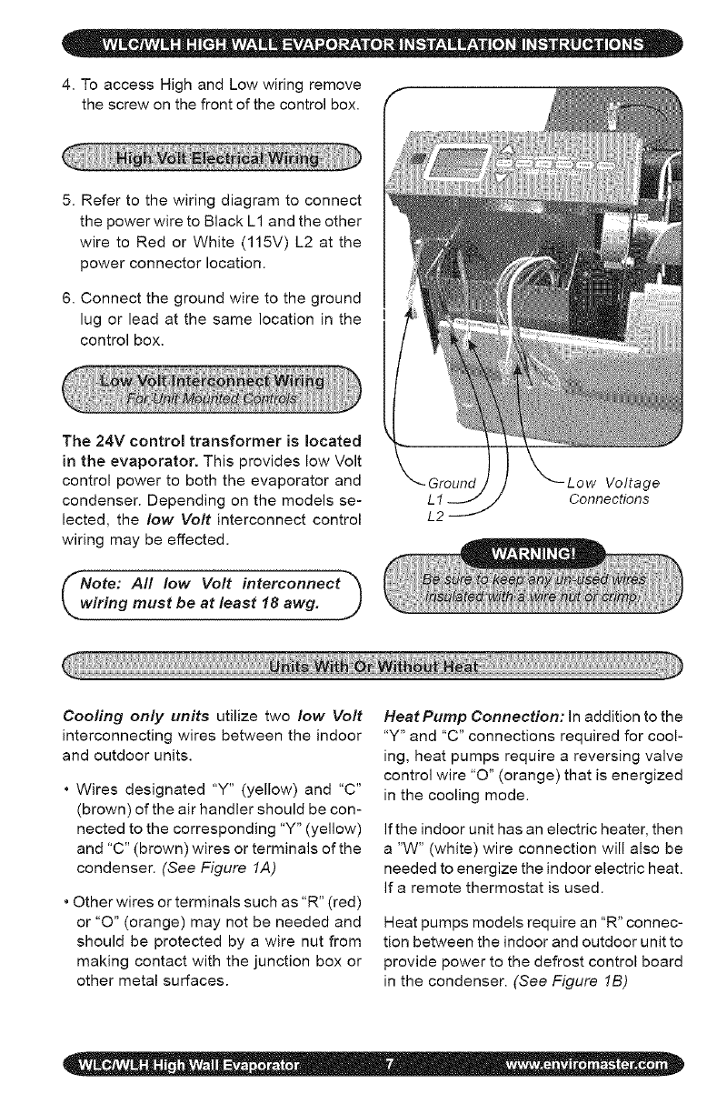
4. To access High and Low wiring remove
the screw on the front of the control box.
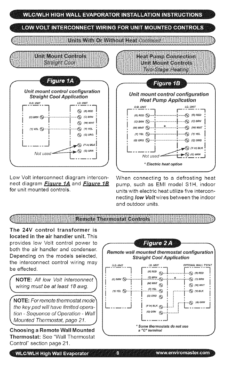
5. Refer to the wiring diagram to connect
the power wire to Black L1 and the other
wire to Red or White (115V) L2 at the
power connector location.
6. Connect the ground wire to the ground
lug or lead at the same location in the
control box.
The 24V control transformer is located
in the evaporator. This provides low Volt
control power to both the evaporator and
condenser. Depending on the models se-
lected, the low Volt interconnect control
wiring may be effected.
Note: All low Volt interconnect *_
rWiHng must be at least 18 awg. J
L2
Voltage
Connections
Cooling only units utilize two low Volt
interconnecting wires between the indoor
and outdoor units.
* Wires designated "Y" (yellow) and "C"
(brown) of the air handler should be con-
nected to the corresponding "Y" (yellow)
and "C" (brown) wires or terminals of the
condenser. (See Figure 1A)
* Other wires or terminals such as "R" (red)
or "O" (orange) may not be needed and
should be protected by a wire nut from
making contact with the junction box or
other metal surfaces.
Heat Pump Connection: in addition to the
"Y" and "C" connections required for cool-
ing, heat pumps require a reversing valve
control wire "0" (orange) that is energized
in the cooling mode.
If the indoor unit has an electric heater, then
a "W" (white) wire connection will also be
needed to energize the indoor electric heat.
If a remote thermostat is used.
Heat pumps models require an "R" connec-
tion between the indoor and outdoor unit to
provide power to the defrost control board
in the condenser. (See Figure 1B)
Unit mount control oonfiguration
Straight Cool Appitcation
__*®1................I'__ _°_i
_ J
Low Volt interconnect diagram intercon-
nect diagram FiL_ure IA and Figure IB
for unit mounted controls.
Unit mount control configuration
Heat Pump App#eadon
_le_et¢ heat @p#@t_
_., .J
When connecting to a defrosting heat
pump, such as EMI model S1H, indoor
units with electric heat utilize five intercon-
necting low Voltwires between the indoor
and outdoor units.
The 24V control transformer is
located in the air handler unit. This
provides low Volt control power to
both the air handler and condenser.
Depending on the models selected,
the interconnect control wiring may
be effected.
_NOTE: All low Volt interconnect_
wiring must be at least 18 awg. J
fNoTE: For remote thermostat mode_
the key pad will have limited opera- I
tion -Sequence of Operation -Wall I
_.Mounted Thermostat, page 21. .t)
Choosing a Remote Wall Mounted
Thermostat: See "Wall Thermostat
Control" section page 21.
Remote wall mounted thermostat configuration
Straifht Cool Appfeattoo
...... q........F{;o=°-
Se_ thermostats de net t_e
_C* termlnat J
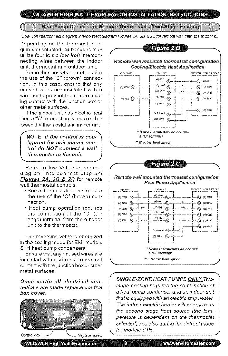
Low Volt interconnect diagram interconnect diagram Fiqures 2A. 2B & 2C for remote wall thermostat control.
Depending on the thermostat re-
quired or selected, air handlers may
utilize four to six low Volt intercon-
necting wires between the indoor
unit, thermostat and outdoor unit.
Some thermostats do not require
the use of the "C" (brown) connec-
tion. In this case, ensure that any
unused wires are insulated with a
wire nut to prevent them from mak-
ing contact with the junction box or
other metal surfaces.
If the indoor unit has electric heat
then a "W" connection is required be-
tween the thermostat and indoor unit.
NOTE: If the control is con- _
figured for unit mount con- I
trot do NOT connect awa!l I
thermostat to the unit. J
Refer to low Volt interconnect
diagram interconnect diagram
Fiures 2A 2B & 2C for remote
wall thermostat controls.
• Some thermostats do not require
the use of the "C" (brown) con-
nection.
• Heat pump operation requires
the connection of the "0" (or-
ange) terminal from the outdoor
unit to the thermostat.
The reversing valve is energized
in the cooling mode for EMI models
S1H heat pump condensers.
Ensure that any unused wires are
insulated with a wire nut to prevent
contact with the junction box or other
metal surfaces.
Once certin all electrical con=
netions are made replace control
box cover,
Replace screw
Remote wait meunt_ thermostat configuration
Cooling/Electric Heat Application
I
_C__rrI_nat
Remote waft meonted thermostat oonfig#ratien
Heat Pomp Appfioa#en
_<'_°°=®-i ........i---__;:__®--i----*---{-"® <"_=
_*_=__ ...................... @ ............... @
........ J I
a _" tertctlia_
f
SINGLE-ZONE HEAT PUMPS ONLY Two-
stage heating requires the combination of
a heat pump condenser and an indoor unit
that is equipped with an electric strip heater.
The indoor electric heater will energize as
the second stage heat source (the tem-
perature is dependent on the thermostat
selected) and also during the defrost mode
for models S 1H.
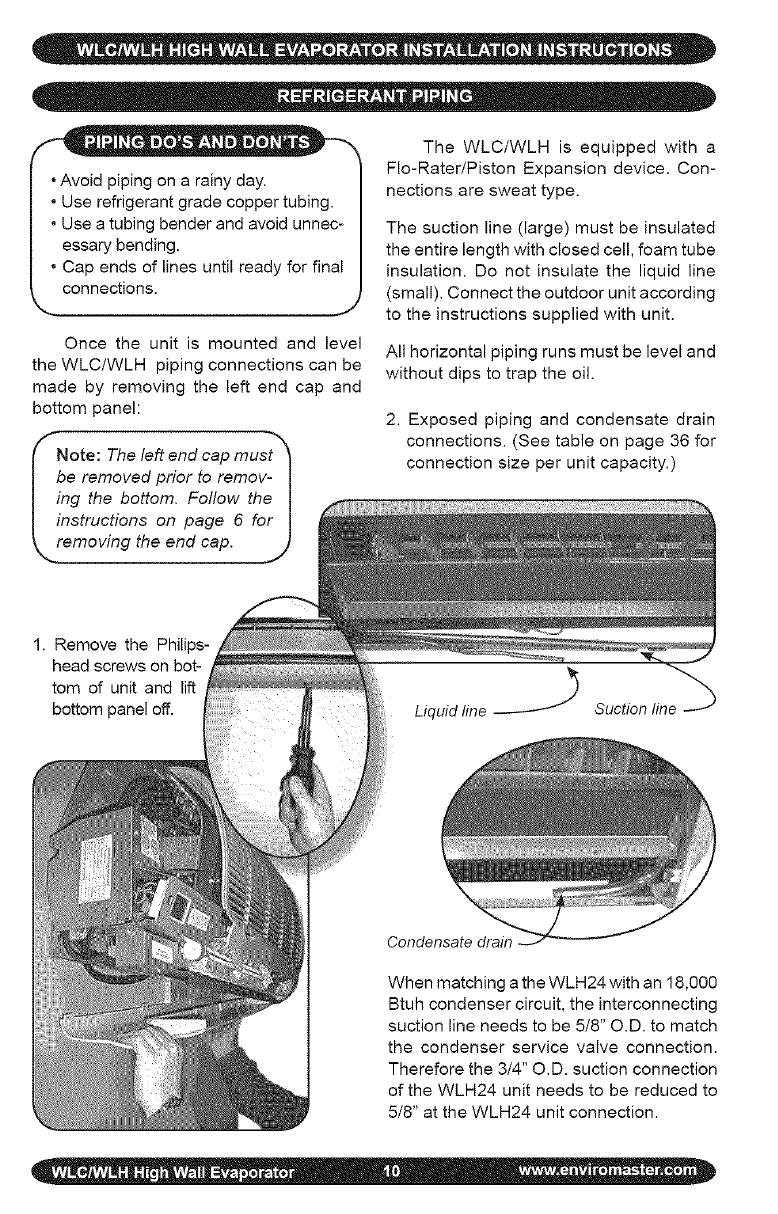
- - _® • _ Be The WLC/WLH is equipped with a
Fie-Rater/Piston Expansion device. Con-
, Avoid piping on a rainy day. nections are sweat type.
• Use refrigerant grade copper tubing.
• Use a tubing bender and avoid unnec-
essary bending.
• Cap ends of lines until ready for final
connections.
J
Once the unit is mounted and level
the WLC/WLH piping connections can be
made by removing the left end cap and
bottom panel:
Note: The left end cap must_
be removed prior to remov- I
ing the bottom. Follow the I
instructions on page 6 for I
removing the end cap. .]j,
The suction line (large) must be insulated
the entire length with closed cell, foam tube
insulation. Do not insulate the liquid line
(small). Connect the outdoor unit according
to the instructions supplied with unit.
All horizontal piping runs must be level and
without dips to trap the oil.
2. Exposed piping and condensate drain
connections. (See table on page 36 for
connection size per unit capacity.)
1. Remove the Philips-
head screws on bot-
tom of unit and lift
bottom panel off. Liquid line Suction line -_
Condensate drain
When matching a the WLH24 with an 18,000
Btuh condenser circuit, the interconnecting
suction line needs to be 5/8" O.D. to match
the condenser service valve connection.
Therefore the 3/4" O.D. suction connection
of the WLH24 unit needs to be reduced to
5/8" at the WLH24 unit connection.
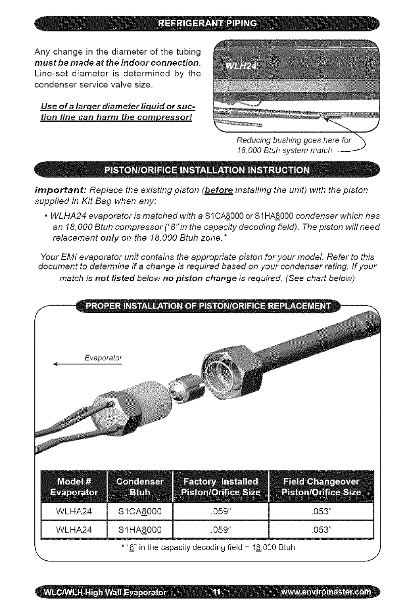
Anychangeinthediameterofthetubing
must be made at the indoor connection.
Line-set diameter is determined by the
condenser service valve size.
Use ofa larqer diameter liquid or suc-
tion line can harm the compressor!
Reducing bushing goes here for "_
18,000 Btuh system match
Important: Replace the existing piston (before instafling the unit) with the piston
supplied in Kit Bag when any:
•WLHA24 evaporator is matched with a S1CAS_000 or $1 HA8000 condenser which has
an 18,000 Btuh compressor ("8"in the capacity decoding field). The piston will need
relacement only on the 18,000 Btuh zone.*
Your EMI evaporator unit contains the appropriate piston for your model. Refer to this
document to determine if a change is required based on your condenser rating. If your
match is not fisted below no piston change is required. (See chart below)
*"8" in the capacity decoding field = 18,000 Btuh
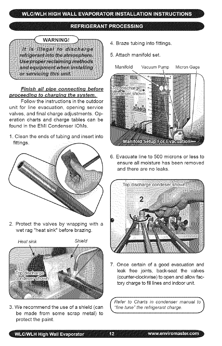
WARNING! 4.Brazetubingintofittings.
5.Attachmanifoldset.
ManifoldVacuumPumpMicron Gage
Finish a!l _ eonnectinq before
roceedin to char in the s stem.
Follow the instructions in the outdoor
unit for line evacuation, opening service
valves, and final charge adjustments. Op-
eration charts and charge tables can be
found in the EMi Condenser IOMs.
1. Clean the ends of tubing and insert into
fittings.
6. Evacuate line to 500 microns or less to
ensure all moisture has been removed
and there are no leaks.
2. Protect the valves by wrapping with a
wet rag "heat sink" before brazing.
Heat sink Shield
7. Once certain of a good evacuation and
leak free joints, back-seat the valves
(counter-clockwise) to open and allow fac-
tory charge to fill lines and indoor unit.
(_Refer to Charts in condenser manual t_
3. We recommend the use of a shield (can L"fine tune" the refrigerant charge.
be made from some scrap metal) to --"
protect the paint.
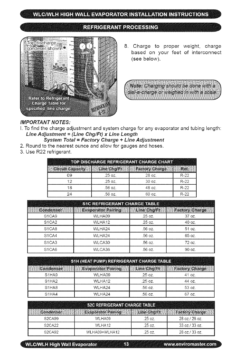
8. Chargeto properweight,charge
basedon yourfeetof interconnect
(seebelow).
IMPORTANT NOTES:
I. To find the charge adjustment and system charge for any evaporator and tubing length:
Line Adjustment =(Line Chg/Ft) x Line Length
System Total =Factory Charge + Line Adjustment
2. Round to the nearest ounce and allow for gauges and hoses.
3. Use R22 refrigerant.
09 25 oz. 28 oz
12 25 oz. 30 oz
18 56 oz. 48 oz
24 56 oz. 60 oz
S1CA9 WLHA09 25 oz. 37 oz.
S1CA2 WLHA12 25 oz. 40 oz.
S1CA8 WLHA24 56 oz. 51 oz.
S1CA4 WLHA24 56 oz. 65 oz.
S1CA3 WLCA30 56 oz. 72 oz.
S1CA6 WLCA36 56 oz. 90 oz.
S1HA9 WLHA09 25 oz 41 oz.
$1 HA2 WLHA12 25 oz 44 oz.
$1 HA8 WLHA24 56 oz 53 oz.
$1 HA4 WLHA24 56 oz 67 oz.
S2CA99 WLHA09 .25 oz. 28 oz./28 oz.
$2CA22 WLHA12 .25 oz. 33 oz./33 oz.
S2CA92 WLHA09+WLHA12 .25 oz. 28 oz./33 oz.
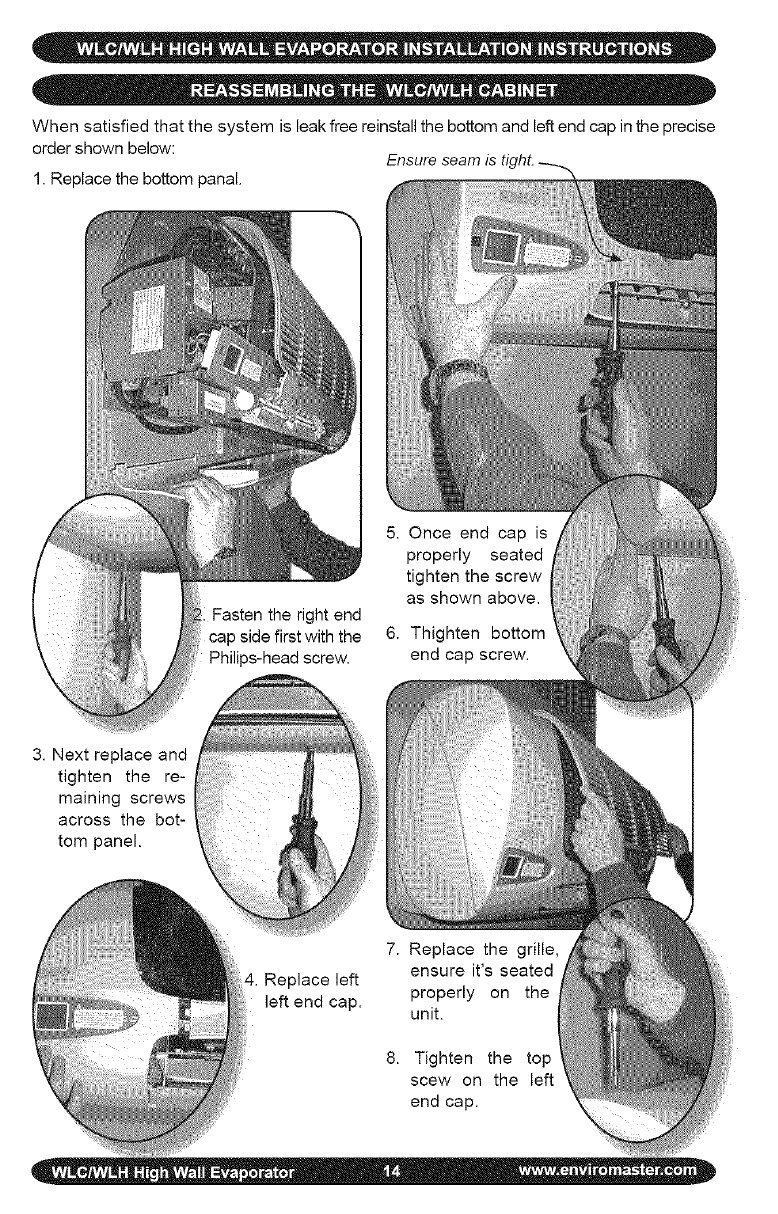
When satisfied that the system is leak free reinstall the bottom and left end cap in the precise
order shown below:
1. Replace the bottom panal.
5. Once end cap is
properly seated
tighten the screw
as shown above.
6. Thighten bottom
end cap screw.
3. Next replace and
tighten the re-
maining screws
across the bot-
tom panel.
4. Replace left
left end cap.
7. Replace the grille,
ensure it's seated
properly on the
unit.
8. Tighten the top
scew on the left
end cap.
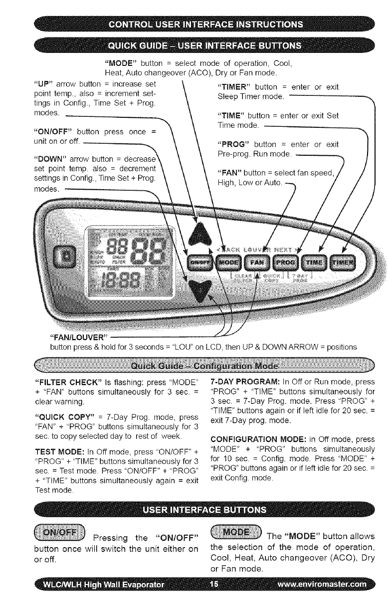
"MODE"button=selectmodeofoperation,Cool,
Heat,Autochangeover(ACO),DryorFanmode.
"UP"arrowbutton=increaseset
pointtemp.,also=incrementset-
tingsinConfig.,TimeSet+Prog.
modes.
"ON/OFF"buttonpressonce=
unitonoroff.
"DOWN"arrowbutton=
setpointtemp.also= decrement
settingsinConfig.,TimeSet+Prog.
modes.
"TIMER"button= enterorexit
SleepTimermode.
"TIME"button=enterorexitSet
Timemode.
"PROG"button= enterorexit
Pre-prog.Runmode.
"FAN"button=selectfanspeed,
High,LoworAuto.
"FAN/LOUVER"
buttonpress&holdfor3seconds="LOU"onLCD,thenUP&DOWNARROW=positions
"FILTERCHECK" Is flashing: press "MODE"
+ "FAN" buttons simultaneously for 3 sec. =
clear warning.
"QUICK COPY" = 7-Day Prog. mode, press
"FAN" + "PROG" buttons simultaneously for 3
sec. to copy selected day to rest of week.
TEST MODE: In Oft mode, press "ON/OFF' +
"PROG *'+ "TIME" buttons simultaneously for 3
sec. = Test mode. Press "ON/OFF" + "PROG"
+ "TIME *' buttons simultaneously again = exit
Test mode.
7-DAY PROGRAM: In Off or Run mode, press
"PROG" + "TIME" buttons simultaneously for
3 sec. = 7-Day Prog. mode. Press "PROG" +
"TIME" buttons again or if left idle for 20 sec. =
exit 7-Day prog. mode.
CONFIGURATION MODE: in Off mode, press
"MODE" + "PROG" buttons simultaneously
for 10 sec. = Config. mode. Press "MODE" +
"PROG" buttons again or if left idle for 20 sec. =
exit Config. mode.
Pressing the "ON/OFF" The "MODE" button allows
button once will switch the unit either on the selection of the mode of operation,
or off. Cool, Heat, Auto changeover (ACO), Dry
or Fan mode.
The"FAN"buttonwillselect
thefanspeed,High,LoworAuto.High
andlowareconstantfanspeedsettings
andcanbeselectedinallmodesexcept
Drymode.InDrymode,thefanwillop-
erateconstantlyat lowspeed.Autofan
modeis notavailableinFan(only),Dry
andRemotewallthermostatmodes.
vermode.Toenterthelouvermodepress
andholdtheFan/Louverbuttonforthree
seconds.Whilein louversetmodethe
word"Lou"willdisplayontheLCD.
The"PROG"buttonisused
to enteror exitthe Pre-programRun
mode.ThePre-programRunmodecan
beenteredwhilethecontrolisin"Cool",
"Heat"or"Auto"modes.Pre-programRun
modecannotbeenteredwhileinDry,
FanorOffmodes.Whilethecontrolisin
Pre-program Run mode the word "PRO-
GRAM" will be displayed on the LCD.
The "TIME" button is used
to enter or exit the Set Time mode. The Set
Time mode can be entered while the con-
trol is in any mode including Off mode. To
enter the Set Time mode, press and hold
the "TIME" button in for three seconds. To
exit press the "TIME" button momentarily.
The "TIMER" button is used
to enter or exit the Sleep Timer mode.
When the "FILTER CHECK" indicator
warning is flashing on the LCD, pressing the
"MODE" and "FAN" buttons simultaneously
for three seconds will clear the warning.
While in 7-day programming mode, press-
ing the "FAN" and "PROG" buttons simul-
taneously for three seconds will copy the
selected day to the rest of the week.
When the unit is either in the Off or Run
mode, pressing the "PROG" and "TIME"
buttons simultaneously for three seconds
will enter the 7-Day Programming mode.
Pressing the "PROG" and "TIME" buttons
again or if left idle for 20 seconds, will exit
the 7-Day program mode.
The "UP" arrow button is used to increase
the set point temperature. Also, the "UP"
arrow button is used to increment settings
in the Configuration, Time Set, Program
and Louver Set modes.
When the unit is in the Off mode, pressing
the "MODE" and "PROG" buttons simulta-
neously for 10 seconds will enter the Con-
figuration mode. Pressing the "MODE" and
"PROG" buttons again or if left idle for 20
seconds, will exit the Configuration mode.
The "DOWN" arrow button is used to de-
crease the set point temperature. Also,
the "DOWN" arrow button is used to dec-
rement settings in the Configuration, Time
Set, Program and Louver Set modes.
The Fan/Louver button is
used to enter the louver mode. The louver
mode allows selection of six different fixed
louver positions or auto (oscillation) Iou-
When the unit is in the Off mode, pressing
the "ON/OFF", "PROG" and "TIME" but-
tons simultaneously for three seconds will
enter Test mode. Pressing the "ON/OFF",
"PROG" and "TIME" buttons simultaneously
again will exit Test mode
fCAUTION:
Do not cycle the unit on and_'_
off repeatedly while in Test mode as this I
will cause damage to the compressor. Do I
not leave the unit in Test mode. ]
For unit mounted key pad operation
the control must be configured through
the Configuration mode. Be sure to select
Remote - OFF in the configuration menu.
(See Configuration mode)
ote: When power is first applied to the_
ontrol or after a power outage there is I
three minute delay before the corn- I
ressor or electric heat will energize. I
is is to protect the unit from short cy- I
ng due to loss of power. ,j
Pressing the "ON/OFF" button once
will switch the unit either on or off. In the
Off mode, the LCD will display the time of
day and day of the week. In the On mode
the LCD display will also display the room
temperature and the mode of operation
Cool, Heat, Auto (Auto changeover), Dry
or Fan mode. While in the On mode, the
set point temperature will display momen-
tarily with the push of any button except
the ON/OFF button.
The FAN button will allow the selection of
the desired fan setting in all modes except
Dry mode. In Dry mode, the fan will oper-
ate constantly at low speed. The LCD will
indicate fan speed selection.
High and Low are constant fan settings.
The fan will operate continuous regardless
of set point or room temperatures. Auto
mode is for cycling fan operation.
Auto Fan mode can only be selected if
the unit is in Heat, Cool or Auto Change-
over modes. In Auto Fan mode the fan
will cycle with the call for Heat or Cool.
Fan speed will be determined by the mi-
croprocessor and speed adjustment will
be made according to room and setpoint
temperatures. The fan will switch to High
speed when room temperature deviates by
more than two degrees from setpoint. The
fan will switch to Low speed if the devia-
tion is one degree or less. When the room
temperature reaches setpoint temperature
the heat/cool call will then be dropped. The
fan will stay on for an additional 60 sec. to
purge unit of any residual energy.
If the Room Air Sampling feature has
been enabled in the Configuration mode
(see Configuration mode), after the fan
has been off for the selected time, it will
then cycle on for 60 seconds. The unit will
circulate room air to remove any temper-
ature stratification by the unit so the mi-
croprocessor can determine an accurate
room temperature. After the 60 second
room air sample time has elapsed, and
if the setpoint temperature remains satis-
fied, the fan will cycle off.
When the unit is in Dry mode the fan
speed will remain constant at Low speed.
While the unit is in Fan mode, Auto is by-
passed and only High or Low are available.
The "MODE" button allows the se-
lection of the mode of operation, Cool,
Heat, Auto changeover (ACO). Dry or
Fan mode. In Fan mode either "HIGH" or
"LOW" will be displayed on the LCD.
The indoor unit utilizes a two-speed
motor with three operational fan modes.
When the control is in the Off mode the
louver will remain in the closed position.
When the unit is turned on via the ON/OFF
button the louver will open and operate ac-
cording to the setting selected in the Lou-
ver Configuration mode.
To enter the Louver Configuration
mode, press and hold the Fan/Louver
button in for three seconds. This will enter
the Louver Configuration mode and "Lou"
will display on the LCD. Pressing the Up
orDownarrowbuttonswillallowselection
of sixdifferentfixedlouverpositionsor
auto(oscillation)mode.Thesequenceis
01,02,03,04,05,06andAuto.Oncethe
desiredsettingisselected,presstheFan/
Louverbuttonmomentarilyorletidlefor
10secondstoexitthelouversetmode.
Whilethecontrolis intheOnmode,
thelouverwill remainin theselected
louverposition.IfAutolouveroperation
isselected,thelouverwilloscillateonly
whenthefanisrunning.Whenthecontrol
isturnedoffviatheON/OFFbuttonthe
louverwillreturntotheclosedposition.
Forcoolingoperationfirstturntheunit
onviatheON/OFFbutton.SelectCool
modeviatheMODEbutton.Theroom
temperatureandsetpointtemperature
willbedisplayed.Thesetpointtempera-
turecanbechangedwitheachsucces-
sivepressoftheUporDownarrowbut-
tonsorbyholdingthebuttonin.
Placethesetpointtemperaturebelow
theroomtemperature.Thecompressor
willstartandcoolingwillcontinuefora
minimumoftwominutesandaslongas
thesetpointremainsbelowroomtemper-
ature.Oncetheroomtemperatureissat-
isfiedforatleast60secondsandthetwo-
minuteminimumruntimehaselapsed
thecompressorwillcycleoff.Thefanwill
operateasdescribedin"FanOperation".
OTE:Once the compressor is_'_
witched off, or after a power outage |
here is a three-minute delay before |
he compressor will re-start. J
J
_,_ Optional Electric Heat Operation
(Non Heat pump condenser units only):
For operation with electric heat the
control must first be configured properly
(Heat source - "ON", Heat pump -"OFF").
See: Configuration Interface mode.
For electric heat operation, first turn the
unit on via the ON/OFF button. Then se-
lect Heat mode via the MODE button. The
room temperature and setpoint tempera-
ture will be displayed. Press either the
Up or Down arrow buttons to change the
setpoint temperature. The setpoint tem-
perature will change by one degree with
each successive press of the Up or Down
arrow buttons. Holding the button in will
change the temperature rapidly.
Place the setpoint temperature above
room temperature. The electric heat will
energize and heating will continue as
long as the setpoint remains above room
temperature. When the room temperature
has been satisfied for at least 60 seconds
and the two minute minimum on time has
expired, the electric heat will switch off.
The fan will operate as described in "Fan
Operation".
_'_ Optional Heat Pump With Electric
Heat (2-stage heating):
For heat pump operation with electric
heat the control must first be configured
properly (Heat source - "ON", Heat pump -
"ON"). See: Configuration Interface mode.
For heat pump operation with backup
electric heat, first turn the unit on via the
ON/OFF button. Then select Heat mode
via the Mode button.
The room temperature and setpoint
temperature will be displayed. Press either
the Up or Down arrow buttons to change
the setpoint temperature. The setpoint
temperature will change by one degree
with each successive press of the Up or
Down arrow buttons. Holding the button in
will change the temperature rapidly.
Place the setpoint temperature above
the room temperature by one degree. The
compressor will start and heating will con-
tinue for a minimum of two minutes and as
long as the setpoint remains above room
temperature. When the room temperature
has been satisfied for at least 60 seconds
and the minimum on time has elapsed,
the compressor will switch off. The fan will
operate as described in "Fan Operation".
Next, place the setpoint temperature
above the room temperature by at least
two degrees. The compressor will start
and, the electric will also energize after a
30 second delay, thus two-stage heating.
The electric heat will run for a minimum
of two minutes and until the deviation
betweenroomtemperatureandsetpoint
temperatureislessthantwodegrees.At
thattimetheelectricheatwillswitchoff
andtheheatpump(compressor)willtake
overtheheatingdemand.Theelectric
heaterwillnotre-startuntilathreeminute
delayhaselapsed.Oncetheroomtem-
peratureissatisfiedandthetwo-minute
minimumruntimehaselapsed,thecom-
pressorwillcycleoff.Thecompressorwill
notre-startuntilathreeminutedelayhas
elapsed.Thefanwilloperateasdescribed
in"FanOperation".
peraturebytwodegrees,heatingwillstop
andcoolingwillcontinuetobringtheroom
temperaturebackdowntosetpointtemper-
ature.Thefanwilloperatecontinuouslyat
lowspeedwhileinDryMode.
Inordertopreventshortcyclingthere
isatwominuteminimumontimeforboth
coolingandheating.Theminimumofftime
is3minutes.Alsothereisa30secondde-
laybetweenthestartof thecompressor
andthestartoftheheatsource.
ForDryModeoperationtheunitmust
haveanelectricheater.Alsothecontrol
mustfirstbeconfiguredproperly(Heat
source-"ON").See:ConfigurationInter-
facemode.
Drymodewillremovehumidityfrom
theairwhilemaintainingaspecificsetpoint
temperature.Thisisdonebyenergizingthe
compressorincoolingalongwiththeelectric
heater.Drymodewillnotmaintainaspecific
humiditylevel.Theunitmustbeequipped
withanoptionalelectricheatelement.
ForDryModeoperation,firstturnthe
unitonviatheON/OFFbutton.SelectDry
modeviatheMODEbutton.Theroom
temperatureandsetpointtemperaturewill
bedisplayed.PresseithertheUporDown
arrowbuttonstochangethesetpointtem-
perature.Thesetpointtemperaturewill
changebyonedegreewitheachsucces-
sivepressoftheUporDownarrowbut-
tons.Holdingthebuttoninwillchangethe
temperaturerapidly.
Placethesetpointtemperatureat a
desiredroomtemperature.Dependingon
thedifferencebetweenroomtemperature
andsetpointtemperaturethecompressor
and/orheatsourcewillenergize.If the
roomtemperatureandsetpointtempera-
turearethesamethecompressorwillop-
erateincoolingandtheelectricheatwill
alsoenergize.
Shouldtheroomtemperaturefallbe-
lowthesetpointtemperaturebytwode-
grees,thecompressorwillstopandheating
willcontinuetoboosttheroomtemperature
backuptosetpointtemperature.Iftheroom
temperaturerisesabovethesetpointtern-
ForAutoChangeoverMode(ACO)
theunitmusthaveaheatsource.Alsothe
controlmustfirstbeconfiguredproperly
(Heatsource- "ON").See:Configuration
Interfacemode.
AutoChangeovermodewilloperate
eitherCoolingmodeor Heatingmode.
Thecontrolwillselectthemodeofopera-
tiondependingonthesetpointtempera-
ture,roomtemperatureandthedifferen-
tialsettingselectedintheConfiguration
mode(SeeConfigurationmode).
ForAutoChangeovermode,firstturn
theunitonviatheON/OFFbutton.Select
AutomodeviatheModebutton.Theroom
temperatureandsetpointtemperaturewill
bedisplayed.PresseithertheUporDown
arrowbuttonstochangethesetpointtem-
perature.Thesetpointtemperaturewill
changebyonedegreewitheachsucces-
sivepressoftheUporDownarrowbut-
tons.Holdingthebuttoninwillchangethe
temperaturerapidly.
Placethesetpointtemperaturebe-
lowtheroomtemperaturebythedead
bandamountselectedintheconfigura-
tionmode.Thecompressorwillstartand
theunitwillruncoolingoperationasde-
scribedunder"CoolMode".
Ifthesetpointtemperatureisabove
theroomtemperaturebythedeadband
amountselectedin the configuration
mode,theunitwillrunheatingoperation
asdescribedunder"HeatMode"
The"TIME"buttonis usedto enter
orexittheSetTimemode.TheSetTime
modecanbeenteredwhilethecontrolisin
anymodeincludingtheOffmode.Toen-
tertheSetTimemode,pressthe"TIME"
buttonin for threeseconds.Pressing
the"PROG"(NEXT)buttonwilladvance
tothenextitem.Theorderis(1)Dayof
week,(2)Hourand(3)Minute.Pressing
the"MODE"(BACK)buttonwillreturnto
thepreviousitem.Thetimeof dayand
dayofweekcanbechangedusingtheup
ordownarrowbuttons.
Whenthe"TIME"buttonis pressed
againorleftidlefor20seconds,thecon-
trolshallsavethenewsettingsandreturn
tothepreviousmode.
The7-dayprogrammingmodeisused
tostorethesettingsforthePre-program
Runmode.
WhentheunitisineithertheOfforRun
mode,the7-DayProgrammingmodecan
beenteredbypressingthe"PROG"and
"TIME"buttonssimultaneouslyforthree
seconds.Whenthe"PROG"and"TIME"
buttonsarepressedsimultaneouslyagain
orleftidlefor20seconds,thecontrolshall
savethenewsettingsandreturntothe
previousinterfacemode.
Whileinthe7-Dayprogrammingmode,
usetheupordownarrowstochangethe
time,temperatureorperiodsettings.Use
the"MODE"(BACK)or"PROG"(NEXT)
buttonstoselectthemodetobechanged.
Settingsfor(1)Dayofweek,(2)Pe-
riodofday,(3)Hour,(4),Minute,(5)Cool
setpointtemperature,(6) Heatsetpoint
temperatureand(7)Autosetpointtem-
peraturecanbeentered.
Quickcopyisa featureofthe7-day
programmingmode.Itisusedtocopythe
settingsofanydaytotherestoftheweek.
Whilein7-dayprogramming,selectthe
dayto becopied.Then,pressthe"FAN"
and"PROG"buttonssimultaneouslyfor
threeseconds.Theselecteddaywillbe
copiedtotherestoftheweek.
Thisisnormaloperating(nonpre-pro-
gramrun)mode.Settingsfortemperature,
modeandfanspeedareselectedbythe
userandwillnotchangewiththepassing
oftime.Theword"PROGRAM"doesNOT
displayontheLCD.
Thisfeatureallowsthesetpointtem-
peraturetobechangedaccordingtothe
pre-programmedsetpointandtimeofday
settings.Thesetpointandtimesettings
areprogrammedintothecontrolthrough
the7-dayprogramminginterface.
ThePre-programmedRunmodecan
beenteredfromCool,HeatorAutomodes
only.Pre-programmedrun modecan-
notbeenteredfromDryorFanmodes.
Pressingthe"PROG"buttonmomentari-
lywillenterorexitthePre-programrun
mode.Theword"PROGRAM"willappear
intheLCDdisplay.Then,withthepass-
ingoftime,thesetpointwillchangetothe
programmedsettingatthetimeselected.
Toaidinfiltermaintenance,themicro-
processorwillkeeptrackoftheunitsrun
time.Then,afterthefilterchecktimehas
elapsed,a"FILTERCHECK"warningwill
appeartheLCDdisplay.Thefiltercheck
timeisselectablethroughtheconfigura-
tionmode.Availablesettingsare250,
500,750,1000,and1250hours.Alsoif
fourevaporatorfreezeupsoccurwithina
24hourperiod,(SeefaultconditionE03)
thefiltercheckindicatorwillappear.
Afterfiltermaintenancehasbeenper-
formed,pressthe"MODE"and"FAN"but-
tonssimultaneouslyforthreesecondsto
clearthefiltercheckwarning.
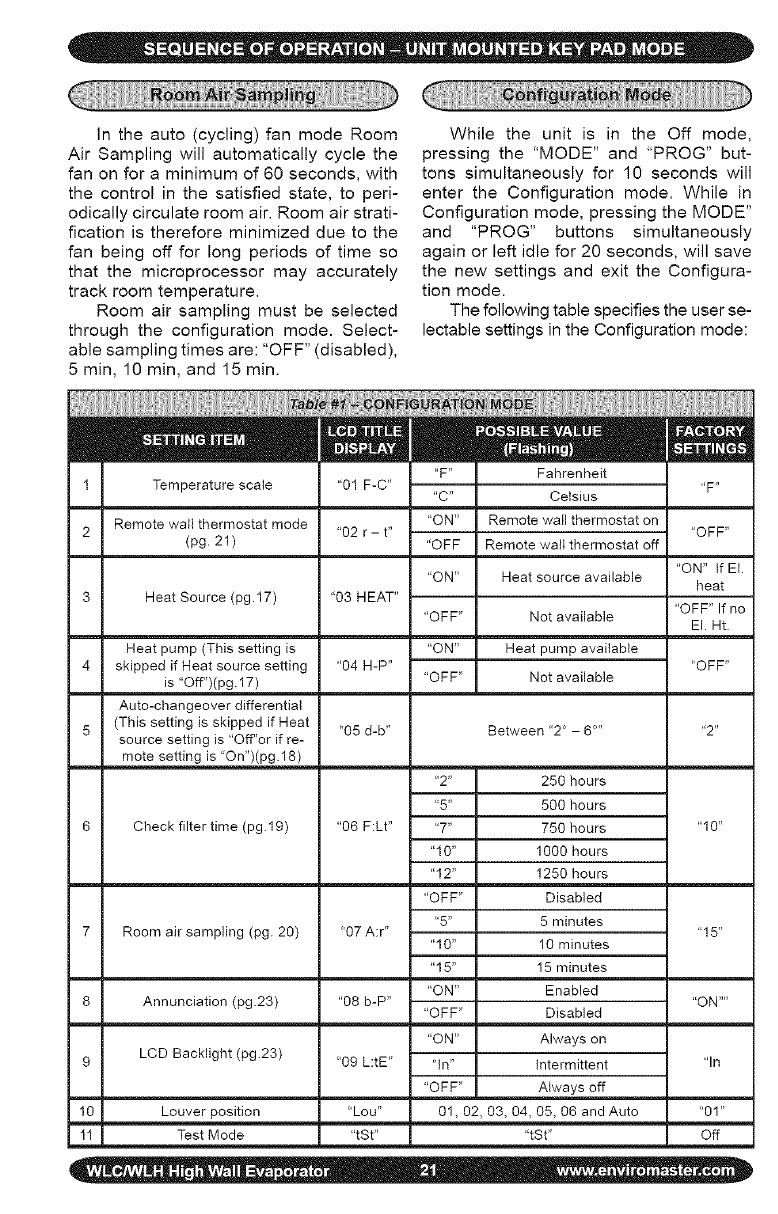
Intheauto(cycling)fanmodeRoom
AirSamplingwillautomaticallycyclethe
fanonforaminimumof60seconds,with
thecontrolinthesatisfiedstate,toperi-
odicallycirculateroomair.Roomairstrati-
ficationisthereforeminimizedduetothe
fanbeingoffforlongperiodsof timeso
thatthemicroprocessormayaccurately
trackroomtemperature.
Roomairsamplingmustbeselected
throughtheconfigurationmode.Select-
ablesamplingtimesare:"OFF"(disabled),
5min,10min,and15min.
Whiletheunitis in the Offmode,
pressingthe"MODE"and"PROG"but-
tonssimultaneouslyfor 10secondswill
entertheConfigurationmode.Whilein
Configurationmode,pressingtheMODE"
and "PROG"buttonssimultaneously
againorleftidlefor20seconds,willsave
thenewsettingsandexittheConfigura-
tionmode.
Thefollowingtablespecifiestheuserse-
lectablesettingsintheConfigurationmode:
"F" Fahrenheit
1 Temperature scale "01F-C" "F"
"C" Celsius
Remote wall thermostat mode "ON" Remote wall thermostat on
2 "02 r - t .... OFF"
(pg. 21 ) "OFF Remote wall thermostat off
"ON" If El.
"ON" Heat source available heat
3 Heat Source (pg.17) "03 HEAT" "OFF" If no
"OFF" Not available El. Ht.
Heat pump (This setting is "ON" Heat pump available
4 skipped if Heat source setting "04 H-P .... OFF"
is "Off")(pg. 17) "OFF" Not available
Auto-changeover differential
5 (This setting is skipped if Heat "05 d-b" Between '2 ° - 6..... 2"
source setting is "Off"or if re-
mote setting is 'On")(pg. 18)
"2" 250 hours
"5" 500 hours
Check filter time (pg.19) "06 F:Lt .... 7" 750 hours "10"
"10" 1000 hours
"12" 1250 hours
"OFF" Disabled
"5" 5 minutes
7 Room air sampling (pg. 20) "07 A:r .... 15"
"10" 10 minutes
"15" 15 minutes
"ON" Enabled
8 Annunciation (pg.23) "08 b-P .... ON ....
"OFF" Disabled
"ON" Always on
9 LCD Backlight (pg.23) "09 L:tE" "In" Intermittent "In
"OFF" Always off
10 Louver position "Lou" 01, 02, 03, 04, 05, 06 and Auto "01"
11 Test Mode "tSt .... tSt" Off
The SLEEP TIMER feature allows the
user, with the push of a single button, to
have the unit switch off using the preset tim-
er. When the control is in the "On" mode,
pressing the "TIMER" will enter or exit the
Sleep Timer mode. When in Sleep Timer
mode, the word "TIMER" will appear on the
LCD display. The unit will continue to oper-
ate for thirty (30) minutes then switch off.
To enter Test mode the control must
first be in the Off mode. Then by press-
ing the "ON/OFF", "PROG" and "TIME"
buttons simultaneously for three seconds
the unit will enter the Test mode. While in
Test mode the display will flash "tSt" pe-
riodically. The operation of the unit can
be checked without having to wait out the
delays. To exit the Test mode press the
"ON/OFF", "PROG" and "TIME" buttons
simultaneously again or by cycling off the
main power to the control.
Test mode is a feature where by all
timers are reduced or eliminated. Test
mode is intended to aid the technician
while checking system operation after in-
stallation or during trouble shooting. Test
mode is not intended for the end user or
for normal operation. Also test mode is
not available while in Remote Wall Ther-
mostat mode".
IAUTION: Do not cycle the unit" I
n and off repeatedly while in Test
ode as this will cause damage to
he compressor. Do not leave the
nit in Test mode J
For Wall mounted thermostat op-
eration the control must be configured
through the Configuration mode. Be sure
to select Remote - ON in the configura-
tion menu. (See Configuration mode)
In Remote Thermostat mode the unit
mounted keypad will have limited capabil-
ity. Some of the buttons will not be oper-
able. Only the FAN and TIME buttons will
function. The ability to clear the FILTER
CHECK warning will also be available by
pressing the MODE and FAN buttons si-
multaneously.
_Choosing a Thermostat:
EMI offers several remote thermostats
that are compatible with the Ductless split
system air handlers. See the latest price
list for a list of available thermostats. It is
important to choose a thermostat that will
match the equipment that you have se-
lected. For single stage cooling or heart-
ing choose a single stage Heat/Cool ther-
mostat. If you have selected an outdoor
heat pump unit and an indoor unit with
electric heat then chose a two-stage heat-
ing, single-stage cooling thermostat.
,_ Selecting a thermostat "by others"
When selecting a thermostat other than
those offered by EMI, it is important to
choose a 24V thermostat that matches
your application. EMI equipment is com-
patible with most mercury bulb, digital or
power steeling thermostats.
_Cooling Only:
Select a thermostat that is compatible
with a cooling system. The thermostat
should have "R", "Y" and "G" terminals
and may also have a "C" terminal.
,_ Cooling only with Electric Heat:
Select a thermostat that is compatible
with a cooling - electric heat system. The
thermostat should have "R", "Y", "W" and
"G" terminals. The thermostat may also
have a "C" terminal.
h;_Heat Pump with Electric Heat:
Select a thermostat that is compatible
with a single stage cooling, two-stage
heat, heat pump system. The thermostat
should have "R", "Y", "O', "W (or W2)"
and "G" terminals. The thermostat may
also have a "C" terminal. If the indoor unit
is not equipped with electric heat then a
single stage heat pump thermostat is ad-
equate.
_" Fan Operation
The indoor unit utilizes a two-speed mo-
tor. The FAN button will allow the selection
of the desired fan speed setting (High or
Low). The wall thermostat will control the
call for fan operation (On or Off) through
the low volt terminals "R" and "G".
After the room thermostat has been sat-
isfied and the call for fan has been re-
moved, the indoor fan to remain on for
an additional 60 seconds. This increases
efficiency by pulling the remaining energy
from the unit.
Some thermostats are equipped with an
"AUTO/ON" fan switch. When this switch
is placed in the "ON" position the indoor
fan will run continuous. When the switch
is in the "AUTO" position the indoor fan will
cycle with the call for heating or cooling.
_ Cooling operation:
The wall thermostat will control the call for
cooling operation (On or Off) through the
low volt terminals "R" and "Y". After con-
necting the thermostat to the unit, place
the system switch in Cool mode. Adjust
the set-point temperature below the room
temperature. The compressor and fan
motors will start and cooling will begin.
Next, place the set-point temperature
above the room temperature. The outdoor
condenser will stop. The fan will operate
as described in Fan Operation.
ote: Once the cooling has cycled off_
r following a power outage, the com- I
ressor will not start for at least three I
inures (See Short Cycle Protection)J
• _/Electric heat operation:
For remote thermostat operation with
electric heat the control must first be
configured properly (Remote - ON, Heat
source- "ON"). See: Configuration Inter-
face mode.
The wall thermostat will control the call for
electric heat operation (On or Off) through
the low volt terminals "R" and "W". After
connecting the thermostat to unit, place
the system switch in Heat mode. Adjust
the set-point temperature above the room
temperature. The electric heat will ener-
gize along with the indoor fan motor. Heat-
ing will continue so long as the set-point
remains above room temperature. Next,
place the set-point temperature below
room temperature. The Electric heater will
switch off and the indoor fan will remain
on for an additional sixty seconds.
!ote: Once the heating has cycled off_
r following a power outage, the heat- I
ng will not resume for at least three I
•_Optional Heat Pump With Electric
Heat (2-stage heating):
For remote thermostat operation for two
stage heating including a heat pump
condenser and indoor electric heat, the
control must first be configured properly
(Remote - ON, Heat source - "ON"). See:
Configuration Interface mode.
The wall thermostat will control the call for
electric heat operation (On or Off) through
the low Volt terminals "R" and "W" for
compressor (heat pump) heating through
terminals "R" and "Y". After connecting the
two stage heating thermostat to the unit,
place the system switch in Heat mode.
Adjust the set-point temperature above
the roomtemperature.Thecompres-
sorandfanmotorswillstartandheating
willbegin.Dependingonthethermostat
selected,electricheatwillalsoenergize
whenthedeviationbetweenroomtem-
peratureandsetpointtemperatureishigh
enoughtocallforsecondstageheating.
(Seethethermostatowner'smanualfor
thisfeature)Placetheset-pointtempera-
turebelowthe roomtemperature.The
outdoorcondenserandelectricheatwill
stopwhiletheindoorfanwillremainonfor
anadditionalsixtyseconds.
•_Short Cycle Protection (ASCT):
The electronic control incorporates an
anti-short cycle timer (ASCT) feature de-
signed to protect the compressor from
short cycling. The ASCT is activated im-
mediately following the off cycle of the
outdoor unit. Once the room temperature
is satisfied and the outdoor unit switches
off, the ASCT will not allow the outdoor to
restart unit a three-minute time period has
elapsed.
This feature will prevent the compres-
sor and heat source from rapid re-starts.
Once switched off, including following a
power outage, the compressor or heat
source shall not re-start for a minimum of
three minutes.
_Staggered Start Protection:
Designed for systems with electric heat,
in heat pump and dry modes the stag-
gered start feature will prevent the com-
pressor and electric heater from starting
simultaneously. There is a thirty-second
delay between the start of the compres-
sor and start of the electric heater while in
Dry mode and Heat pump mode.
A__Minimum Run Time:
Once started, the minimum on time pre-
vents either the compressor or heat
source from cycling off prematurely. The
minimum ON time for both the compressor
and electric heat is two minutes. Minimum
on time is available only while the control
is configured for Unit mounted keypad op-
eration. Minimum on times are disables
while in Remote thermostat mode.
A¢ LCD Back Light:
The LCD display can be illuminated using
the LCD back light feature. The selectable
settings are "Off", "On", and "intermittent"
and can be set in the Configuration mode.
By selecting "Off" the backlight will remain
offat all times. By selecting "On" the back-
light will remain on at all times including
while in the Off mode interface. If "Inter-
mittent" is selected, the backlight will re-
main for 10 seconds after the push of any
button while the control is in the On mode
or after the push of the "ON/OFF" button
while in the Off mode interface.
A_ Drain Pan Sensor:
The drain pan sensors monitor the con-
densate level in each of the units drain
pans. Should the water in either pan
reach a critical level, the monitor will auto-
matically signal the main control unit. The
controls microprocessor will in turn switch
off the condensing unit for a minimum of
three minutes and until the fault condi-
tion has been cleared, to prevent further
condensate production. A fault code "E02"
will then flash on the controls LCD display
and will automatically reset once the fault
condition is cleared.
A_'Annunciation:
The unit is equipped with an annunciation
feature where by the control will beep pro-
viding the user with audio feedback confirm-
ing that the microprocessor has received its
commands. The annunciation feature must
be activated in the Configuration mode. The
selections are "Off" and "On". If "Off" is se-
lected, annunciation will remain off. If "On"
is selected then annunciation will beep with
the push of any button in the On mode or
with the push of the "ON/OFF" button while
in the Off mode interface.
ote: While in Remote thermostat_
ode (see configuration), only the|
N" and "TIME" buttons are acti-|
ated and will beep when pressed. J
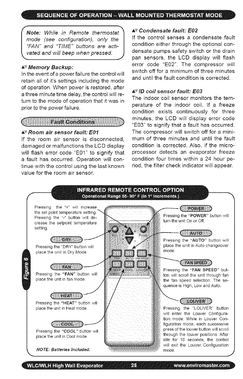
_' Memory Backup:
In the event of a power failure the control will
retain all of it's settings including the mode
of operation. When power is restored, after
a three minute time delay, the control will re-
turn to the mode of operation that it was in
prior to the power failure.
_s Room air sensor fault: E01
If the room air sensor is disconnected,
damaged or malfunctions the LCD display
will flash error code "E01" to signify that
a fault has occurred. Operation will con-
tinue with the control using the last known
value for the room air sensor.
A_ Condensate fault: E02
If the control senses a condensate fault
condition either through the optional con-
densate pumps safety switch or the drain
pan sensors, the LCD display will flash
error code "EO2". The compressor will
switch off for a minimum of three minutes
and until the fault condition is corrected.
_ID coil sensor fault: E03
The indoor coil sensor monitors the tem-
perature of the indoor coil. If a freeze
condition exists continuously for three
minutes, the LCD will display error code
"E03" to signify that a fault has occurred.
The compressor will switch off for a mini-
mum of three minutes and until the fault
condition is corrected. Also, if the micro-
processor detects an evaporator freeze
condition four times within a 24 hour pe-
riod, the filter check indicator will appear.
Pressing the "+" will increase
the set point temperature settinc
Pressing the "-" button will de-
crease the setpoint temperature
setting
Pressing the "DRY" button will
place the unit in Dry Mode
Pressing the "FAN" button will
place the unit in fan mode
Pressing the "POWER" button will
turn the unit On or Off.
Pressing the "AUTO" button will
place the unit in Auto changeover
mode.
Pressing the "FAN SPEED" but-
ton will scroll the unit through fan
the fan speed selection. The se-
quence is High, Low and Auto.
Pressing the "HEAT" button will
place the unit in Heat mode.
Pressing the "COOL" button will
place the unit in Cool mode
NOTE: Batteries Included.
Pressing the "LOUVER" button
will enter the Louver Configura-
tion mode While in Louver Con-
figuration mode, each successive
pressof the louver buttonwill scroll
through the louver positions. After
idle for 10 seconds, the control
will exit the Louver Configuration
mode. ,J
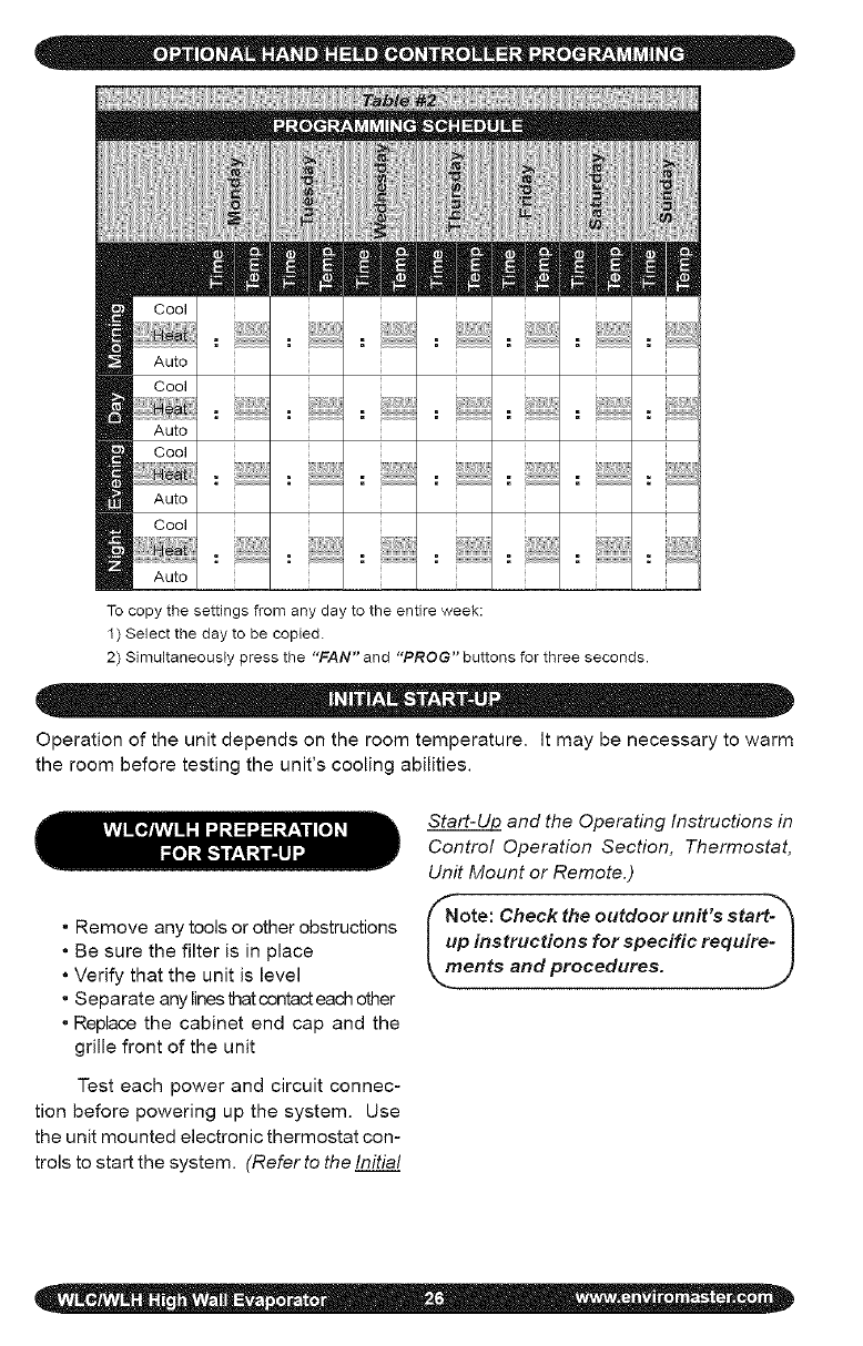
To copy the settings from any day to the entire week:
1) Select the day to be copied.
2) Simultaneously press the "FAN" and "PROG" buttons for three seconds.
Operation of the unit depends on the room temperature. It may be necessary to warm
the room before testing the unit's cooling abilities.
• Remove any tools or other obstructions
• Be sure the filter is in place
• Verify that the unit is level
• Separate any lines that contact each other
• Replace the cabinet end cap and the
grille front of the unit
Test each power and circuit connec-
tion before powering up the system. Use
the unit mounted electronic thermostat con-
trols to start the system. (Refer to the Initial
Start-Ul2 and the Operating Instructions in
Control Operation Section, Thermostat,
Unit Mount or Remote.)
_ote: Check the outdoor unit's start-_
p instructions for specific require- I
ents and procedures. ]
j,
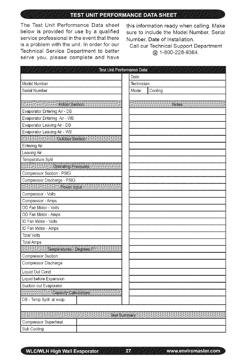
TheTestUnitPerformanceDatasheet
belowisprovidedforusebya qualified
serviceprofessionalintheeventthatthere
isaproblemwiththeunit.Inorderforour
TechnicalServiceDepartmentto better
serveyou,pleasecompleteandhave
thisinformationreadywhencalling.Make
suretoincludetheModelNumber,Serial
Number,DateofInstallation.
CallourTechnicalSupportDepartment
@1-800-228-9364.
iModelNumber
SerialNumber
Date:
Technician:
Mode:ICooling
EvaporatorEnteringAir-DB
EvaporatorEnteringAir-WB
iEvaporatorLeavingAir-DB
iEvaporatorLeavingAir-WB
EnteringAir
iLeavingAir
TemperatureSplit
iCompressor Suction - PSIG
Compressor Discharge - PSIG
iCompressor - Volts
Compressor - Ampe
OD Fan Motor- Volts
OD Fan Motor- Amps
IDFan Motor- Volts
IDFan Motor-Amps
TotalVolts
Compressor Suction
Compressor Discharge
Liquid Out Cond
Liquid before Expansion
Suction out Evaporator
DB - Temp Split at evap.
I
CompressorSuperheat
SubCooling
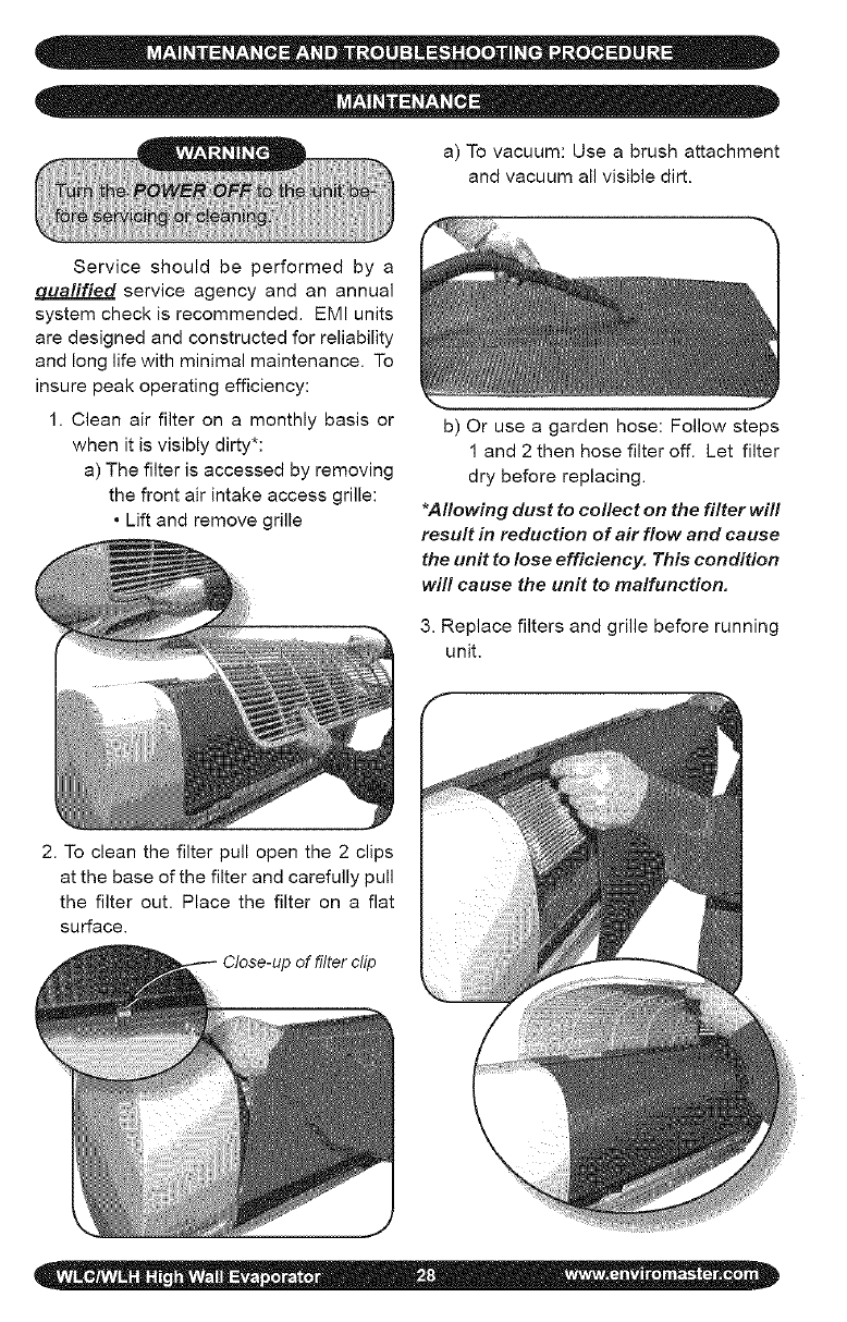
a)Tovacuum:Useabrushattachment
andvacuumallvisibledirt.
Serviceshouldbeperformedbya
£1ualifiedserviceagencyandanannual
systemcheckisrecommended.EMIunits
aredesignedandconstructedforreliability
andlonglifewithminimalmaintenance.To
insurepeakoperatingefficiency:
1.Cleanairfilterona monthlybasisor
whenitisvisiblydirty*:
a)Thefilterisaccessedbyremoving
thefrontairintakeaccessgrille:
•Liftandremovegrille
b)Oruseagardenhose:Followsteps
1and2thenhosefilteroff.Letfilter
drybeforereplacing.
*Allowing dust to collect on the filter will
result in reduction of air flow and cause
the unit to lose efficiency. This condition
will cause the unit to malfunction.
3. Replace filters and grille before running
unit.
2. To clean the filter pull open the 2 clips
at the base of the filter and carefully pull
the filter out. Place the filter on a flat
surface.
of filter clip
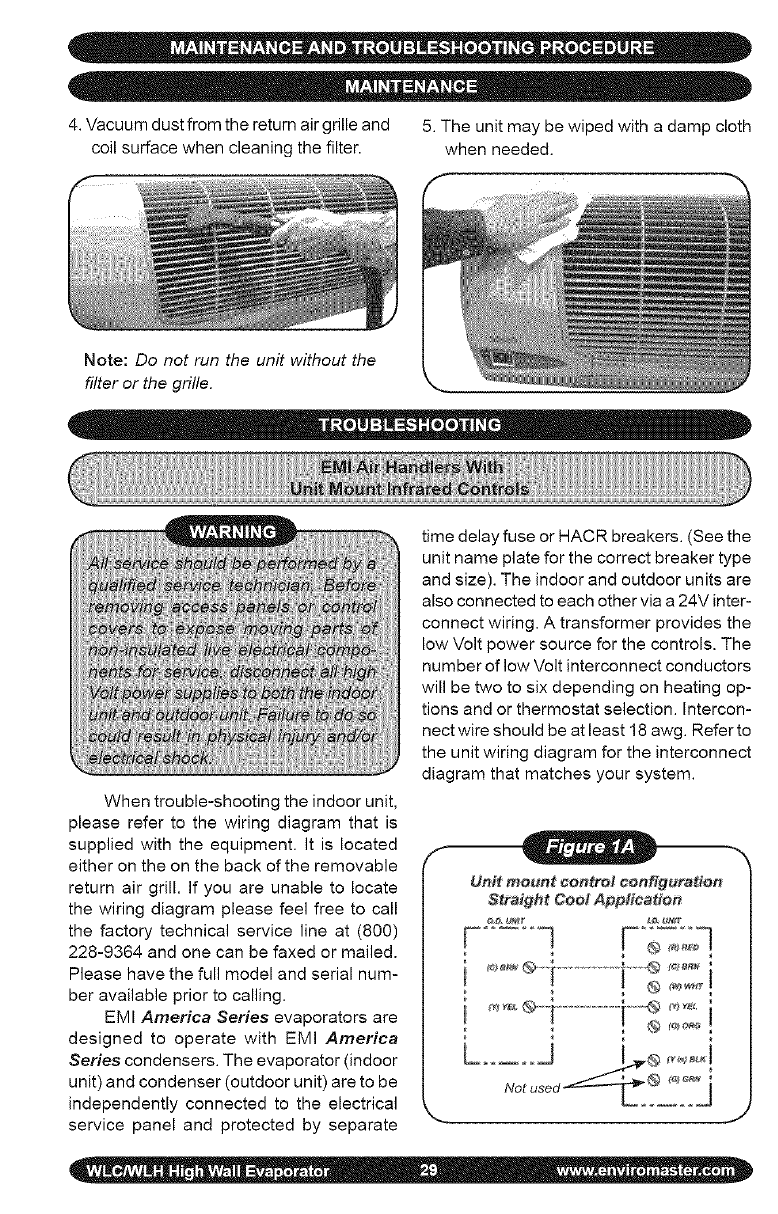
4. Vacuum dust from the return air grille and 5. The unit may be wiped with a damp cloth
coil surface when cleaning the filter, when needed.
Note: Do not run the unit without the
filter or the grille.
When trouble-shooting the indoor unit,
please refer to the wiring diagram that is
supplied with the equipment. It is located
either on the on the back of the removable
return air grill. If you are unable to locate
the wiring diagram please feel free to call
the factory technical service line at (800)
228-9364 and one can be faxed or mailed.
Please have the full model and serial num-
ber available prior to calling.
EMI America Series evaporators are
designed to operate with EMI America
Series condensers. The evaporator (indoor
unit) and condenser (outdoor unit) are to be
independently connected to the electrical
service panel and protected by separate
time delay fuse or HACR breakers. (See the
unit name plate for the correct breaker type
and size). The indoor and outdoor units are
also connected to each other via a 24V inter-
connect wiring. A transformer provides the
low Volt power source for the controls. The
number of low Volt interconnect conductors
will be two to six depending on heating op-
tions and or thermostat selection. Intercon-
nect wire should be at least 18 awg. Refer to
the unit wiring diagram for the interconnect
diagram that matches your system.
Unit mount ¢entro/ configuration
Heat Pump Application
' !
Remote wall mounted thermostat configuration i
Heat Pump Application
F:;2;] -F:;;;q ......................
jJ
aeta a meu ted thermostatcoo guration
Straight CootApplication
c]F;;=;q...........F;;,::]
J
When trouble shooting any EMI prod-
uct, it is important to first check the rating
plate for proper field voltage and breaker
size. Secondly using a voltmeter check the
incoming power supply to see that it agrees
with the rating plate. The incoming power
should not exceed the nameplate voltage.
Also, the incoming power should not be
below the minimum voltage stated on the
rating plate (197V for units rated 208/230V
and 104V for units rated 115V).
A check for low voltage power should
also be made. By placing a voltmeter
across low Volt terminals "R" and "C" at
the indoor unit, there should be a reading
of 24V.
TestMode is available for unit mounted
control configuration only. Use of test mode
can aid in the functional check of the unit.
It can also be a helpful tool when trouble
shooting to solve a problem.
To enter test mode, while the unit is in
off mode, press "On/Off", 'PROG" AND
"Time" buttons simultaneously for three
seconds. To exit press again or remove
power to the unit. While in test mode all
timers are shortened.
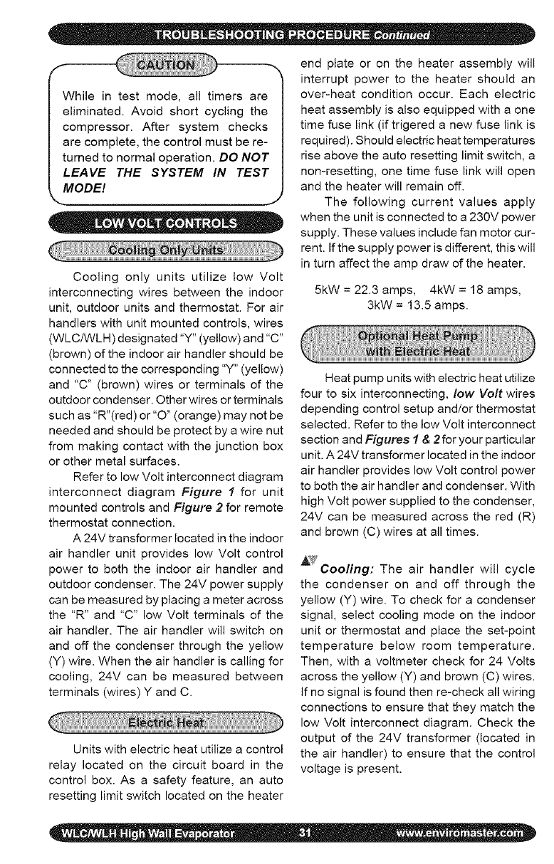
While in test mode, all timers are
eliminated. Avoid short cycling the
compressor. After system checks
are complete, the control must be re-
turned to normal operation. DO NOT
LEAVE THE SYSTEM IN TEST
MODEl
•• • =e
Cooling only units utilize low Volt
interconnecting wires between the indoor
unit, outdoor units and thermostat. For air
handlers with unit mounted controls, wires
(WLC/WLH) designated "Y" (yellow) and "C"
(brown) of the indoor air handler should be
connected to the corresponding "Y" (yellow)
and "C" (brown) wires or terminals of the
outdoor condenser. Other wires or terminals
such as "R"(red) or "O" (orange) may not be
needed and should be protect by a wire nut
from making contact with the junction box
or other metal surfaces.
Refer to low Volt interconnect diagram
interconnect diagram Figure I for unit
mounted controls and Figure 2 for remote
thermostat connection.
A 24V transformer located in the indoor
air handler unit provides low Volt control
power to both the indoor air handler and
outdoor condenser. The 24V power supply
can be measured by placing a meter across
the "R" and "C" low Volt terminals of the
air handler. The air handler will switch on
and off the condenser through the yellow
(Y) wire. When the air handier is calling for
cooling, 24V can be measured between
terminals (wires) Y and C.
Units with electric heat utilize a control
relay located on the circuit board in the
control box. As a safety feature, an auto
resetting limit switch located on the heater
end plate or on the heater assembly will
interrupt power to the heater should an
over-heat condition occur. Each electric
heat assembly is also equipped with a one
time fuse link (if trigered a new fuse link is
required). Should electric heat temperatures
rise above the auto resetting limit switch, a
non-resetting, one time fuse link will open
and the heater will remain off.
The following current values apply
when the unit is connected to a 230V power
supply. These values include fan motor cur-
rent. If the supply power is different, this will
in turn affect the amp draw of the heater.
5kW = 22.3 amps, 4kW = 18 amps,
3kW = 13.5 amps.
Heat pump units with electric heat utilize
four to six interconnecting, low Volt wires
depending control setup and/or thermostat
selected. Refer to the low Volt interconnect
section and Figures 1&2for your particular
unit. A 24V transformer located in the indoor
air handler provides low Volt control power
to both the air handler and condenser. With
high Volt power supplied to the condenser,
24V can be measured across the red (R)
and brown (C) wires at all times.
A?fCooling: The air handler will cycle
the condenser on and off through the
yellow (Y) wire. To check for a condenser
signal, select cooling mode on the indoor
unit or thermostat and place the set-point
temperature below room temperature.
Then, with a voltmeter check for 24 Volts
across the yellow (Y) and brown (C) wires.
If no signal is found then re-check all wiring
connections to ensure that they match the
low Volt interconnect diagram. Check the
output of the 24V transformer (located in
the air handler) to ensure that the control
voltage is present.
EMIheatpumpsystemsutilizeareversing
valveisthatisenergizedinthecooling
mode.Thereversing-valvesignalisprovided
throughtheorange(O)lowVoltwireofthe
airhandlerorthermostat.Itshouldremain
energizedconstantlyaslongastheindoor
unitorthermostatremainsincoolingmode.
Tocheckfor24Vreversingvalvevoltage,at
theoutdoorunit,placeavoltmeteracross
thebrown(C)andorange(O)wireswhile
inthecoolingmode.
_Heating: Heatpumpunits can
accommodate two-stage heating when
an optional electric strip heater is present
along with a heat pump condenser. The
first stage being the compressor and the
second is electric heat. The air handler or
wall thermostat will cycle the condenser
through the yellow (Y) wire as it does
in cooling however the reversing valve
will no___ttbe energized. To check for a
condenser signal, place the indoor unit or
wall thermostat in heating. Next place the
set-point temperature one degree above
room temperature to call the first stage of
heating. Then, with a voltmeter check for
24 Volts across the yellow (Y) and brown
(C) wires at the condenser. The electric
heat should be off at this point. Select a
set-point temperature that is more than
two degrees above the room temperature
to call for the second stage of heating. The
electric heat should energize along with
the 24V compressor signal between "Y"
and "C". Check to see that the amp draw
corresponds with the electric heat rating.
The following current values apply
when the unit is connected to a 230V power
supply. These values include indoor fan mo-
tor current. If the supply power is different,
this will affect the amp draw of the heater.
Units with electric heat utilize a control
relay located on the circuit board in the
control box. As a safety feature, an auto
resetting limit switch located on the heater
end plate or on the heater assembly will
interrupt power to the heater should an over-
heat condition occur. Each electric heat
assembly is also equipped with a one time
fuse link. Should electric heat temperatures
rise above the auto resetting limit switch, a
non-resetting, one time fuse link will open
and the heater will remain off (to restart a
new fuse link is required).
EMI Air Handlers are available with an
optional condensate pump. Condensate
pumps are recommended when it is not
possible to gravity drain the condensation
from the indoor unit. Depending on the
pump manufacture the maximum lift for the
pump will vary. Consult the pump instruc-
tions for the maximum lift for the particular
pump being used.
Condensation generated by the evapo-
rator will collect in the pumps' reservoir.
When the water level is high enough, a float
switch will close and energize the pump
motor clearing the water from the reservoir.
Should for any reason the water exceed the
maximum preset level, a safety switch will
open, there by interrupting the (Y) signal to
the condenser. This will prevent the evapo-
rator from generating more condensation
and spilling out of the unit.
5kW = 22.3 amps, 4kW = 18 amps,
3kW = 13.5 amps.
Q:Thesystemhasjustbeeninstalledus-
inganEMIindoorunitanda non-EMI
condenser.Thereisnodisplayandthe
unitwillnotoperate.
A: EMIairhandlersaremanufacturedwith
alowVolttransformerinstalled.When
connectinganEMIevaporatortoanon-
EMIcondenser,checktoensurethat
thereisno24Vcontroltransformerin
theoutdoorunit.Onlyonetransformer
isrequired.Ifboththeindoorunitand
outdoorunitcontainatransformer,one
mustberemovedfromthesystem.
Q:Thecondenserwillnotstartalthough
theindoorunitappearsnormal.What
shouldIdo?
A: Attheindoorunit,makesurethatthe
controlisincoolingandthesetpoint
temperatureisbelowroomtemperature.
Next,usingavoltmeter,checkfor24V
acrosstheyellow(Y)andbrown(C)
wires.If24Vispresentthencheckfor
wiringbreaksorimproperconnections
betweentheindoorandoutdoorunits.
A: Some EMI condensers are equipped
with a manual reset high-pressure
switch. It is located on the high side of
the refrigerant system usually on the
discharge line of the compressor. To
reset, simply push the red button in. If
the switch was tripped there will be a
"click" when it resets.
A: If the unit is equipped with a condensate
pump check to see if the safety float
has been tripped. This can be done by
first disconnecting both ends of the float
switch. Then with an Ohmmeter, check
for continuity across the switch. If the
switch is open then the pump is not
clearing or the switch may be bad.
Q: The display on the indoor unit is blank.
What should I do?
A: Check the power supply (see "Power
supply check" Section). If the unit still
fails to turn on via the On/off button
then inspect the control box for any
apparent wires that may have come
loose during shipping. Also inspect the
circuit boards for burnt components. If
no obvious problem can be found then
replace all circuit boards including the
unit keypad. Do not attempt to trouble
shoot the individual circuit boards.
Q: The display tends to flicker at times. Is
this normal?
A: A small amount of flickering of the dis-
play is normal. Depending on the room
lighting, flickering may be noticeable at
some times more than others.
Q: How long will the fan run?
A: While the unit is in cooling or heating
and auto fan mode is selected, Fan
speed will be determined by the micro-
processor and speed adjustment will be
made according to room and setpoint
temperatures. The fan will switch to
High speed when room temperature
deviates by more than two degrees
from setpoint. The fan will switch to Low
speed if the deviation is one degree.
When the room temperature reaches
setpoint temperature the heat/cool call
is dropped. The fan will then stay on for
an additional 60 seconds to purge unit
of any residual energy. If High or Low
is selected then the fan will operate
continuous regardless of set point or
room temperatures.
Q: What causes my indoor unit to freeze-up?
A: Evaporator freeze up is usually the
symptom of another problem. Units with
infrared compatible, unit mounted con-
trols are equipped with freeze protection
topreventfreezeupfromoccurring.If
freezeupdoesoccurthencheckthe
following.
• Checkthatthefreezesensorlocated
inthelowestpartofthecoil.Generally
thisiswherefreezeupwillbegin.
• Checkthatthefreezesensorinserted
fullyandsnuginthecoilfin.Ifnot
anotherlocationmayneedto be
selected.Becarefulnottoinsertthe
sensordirectlyintothecoiltuberather
insertthesensorbetweentwotubes.
• Checktheindoorairfilter.Itshould
becleanandfreeofdirt.Adirtyfilter
willreduceairflowandefficiency.
Alsocheckthatthecoilisclean.
Ifthecoilisdirtythenitshouldbe
cleanedusinganappropriatecoil
cleanerormilddetergent.
Istheequipmentbeingoperated
in coolingmodewhenoutdoor
temperaturesarebelow60°F?Ifit
is,thenthecondensershouldbe
fittedwithlowambientcontrolso
thatthepropersystempressures
aremaintained.
Doesthesystemhavetheproper
refrigerantcharge?A systemlow
onrefrigerantcancauseevaporator
freeze-up.Tochecksystemcharge
youwillneedtocontactaqualified
refrigerationservicetechnician.
Refrigerantchargeinformationcan
befoundin IOMfortheoutdoor
condensingunit.
NOTE:Due to EMI's ongoing development programs,
design and specifications may change without notice.
B
t_1 ½"
t
WLHA09
WLHA12
WLHA24
WLCA30
WLCA36
Z
HE
26 ½"
26 ½"
36 ½"
46 ½"
46 ½"
WLHA09 58.00
WLHA12 60.25
WLHA24 66.20
WLCA30 90.10
WLCA36 91.10
09/12 45
18/24 56
30/36 60
MODEL
#
m
09/12
VOLTSIHZIPH HP
I15/60/1 0.02
I15/60/1 0.02
208/230/60/1 0.02
208/230/60/1 0.02
0.083
0.083
0.083
0.070
0.070
0.070
208/230/60/1 1/I0
208/230/60/I 1/10
115/60/1
115/60/1
I15/60/1
208/230/60/I
208/230/60/1
208/230/60/I
24
m
30/36
HEATER
K.W.
0.75
3.00
0.75
1.25
3.00
5.00
5.00
AIViPS
6.50
13.04
E
6.52
10.90
TOTAL
AMPS
0.64
7.14
0.34
13.38
1.20
7.72
12.10
0.56
13.04 13.60
21.74 22.30
- 0.80
21.74 22.54
m
MIN
VOLT
I04
I04
197
197
104
104
I04
I97
197
I97
197
I97
m m
HACR
M.C.A. BRKR
0.8 15
8.9 15
0.4 15
16.7 20
1.5 15
9.7 15
15.1 20
0.7 15
17.0 20
27.9 30
1.0 15
28.2 30
E
M_
o_
3(
3
l-'lld 11_
4OO
75O
1,100
35(
37._
)oc
ARI Standard ARI Standard
2101240UAC 2!10t240UHP
)ry 900 15
)ry 1,225 25
)ry 1,250 27
09
12
18
24
30
36
*WLC/WLH Suction Connection size is 3/4" O.D.
and must bush down at the WLC/WLH UniL
** WLC Suction Connection size is 5/8" O.D. a
factory supplied kit is provided to transition to
3/4" O.D. interconnect.
!
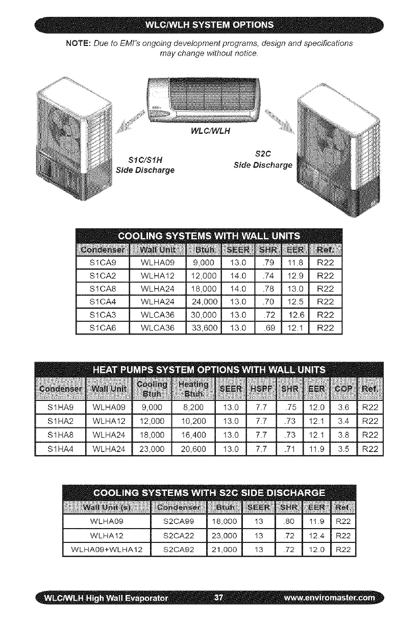
NOTE: Due to EMI's ongoing development programs, design and specifications
may change without notice.
WLC/WLH
S2C
SIC/SIH
Side Discharge Side Discharge
S1CA9 WLHA09
S1CA2 WLHA12
S1CA8 WLHA24
S1CA4 WLHA24
S1CA3 WLCA36
m
S1CA6 WLCA36
..................[[[[[R_[ [
11.8 R22
12.9 R22
13.0 R22
12.5 R22
12.6 R22
12.1 R22
S1HA9 WLHA09 8,200
S1HA2 WLHA12 I0,200
S1HA8 WLHA24 I6,400
S1HA4 WLHA24 20,600
_EEF NSPF
13.0 7.7
13.0 7.7
13.0 7.7
13.0 7.7
mE m
-5 12.0 3.6
.?3 12.1 3.4
.?3 12.1 3.8
.71 11.9 3.5
||
:_2
R2
:_2
:_2
WLHA09 S2CA99
WLHA12 S2CA22
WLHA09+WLHA12 S2CA92
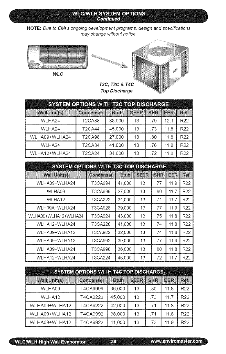
NOTE: Due to EMI's ongoing development programs, design and specifications
may change without notice.
WLC
T2C, T3C & T4C
Top Discharge
36,000 13 .79 12.1 R22
45,000 13 .73 11.8 R22
27,000 13 .80 11.8 R22
41,000 13 .76 11.8 R22
34,000 13 .72 11.8 R22
WLHA24 T2CA88
WLHA24 T2CA44
WLHA09+WLHA24 T2CA98
WLHA24 T2CA84
WLHA12+WLHA24 T2CA24
WLHA09+WLHA24 T3CA994 41,000 13 .77 11.9 R22
WLHA09 T3CA999 27,000 13 .80 11.7 R22
WLHA12 T3CA222 34,000 13 .71 11.7 R22
WLH09A+WLHA24 T3CA928 39,000 13 .77 11.9 R22
WLHA09+WLHA12+WLHA24 T3CA924 43,000 13 .75 11.8 R22
WLHA12+WLHA24 T3CA228 41,000 13 .74 11.8 R22
WLHA09+WLHA12 T3CA922 32,000 13 .74 11.8 R22
WLHA09+WLHA12 T3CA992 30,000 13 .77 11.9 R22
WLHA09+WLHA24 T3CA998 36,000 13 .80 11.8 R22
WLHA12+WLHA24 T3CA224 46,000 13 .72 11.7 R22
zE mm
tun EER _HR Ref.
WLHA09 T4CA9999 ,000 13 .80 1.8 R22
WLHA12 T4CA2222 ,000 13 .73 1.7 R22
WLHA09+WLHA12 T4CA9222 ,000 13 .71 1.8 R22
WLHA09+WLHA12 T4CA9992 ,000 13 .71 1.8 R22
WLHA09+WLHA12 T4CA9922 ,000 13 .73 1.9 R22
ALL PRODUCT LiMiTED WARRANTY
Enviromaster International LLC (EMI) warrants to the purchaser/owner that EMI prod-
ucts will be free from defects in material and workmanship under the normal use and
maintenance for a period of twelve months for all components and sixty months on unit
compressors from the date of original installation, or fifteen months for all components
and sixty-three months on unit compressors from the date of manufacture, whichever
comes first.
WHAT WE WILL COVER
EMI will replace any defective part returned to EMI's approved service organization with
a new or rebuilt part at no charge. The replacement part assumes that unused portion
of this warranty.
WHAT WE DON'T COVER
THIS WARRANTY DOES NOT iNCLUDE LABOR or other costs incurred for repairing,
removing, installing, shipping, servicing, or handling of either defective or replacement
parts.
EMI IS NOT RESPONSIBLE FOR:
*Normal maintenance
*Damage or repairs required as a consequence of faulty installation or application by
others.
,Failure to start due to voltage conditions, blown fuses, open circuit breakers, or other
damages due to the inadequacy or interruption of electrical service.
o Damage or repairs needed as a consequence of any misapplication, abuse, improper
servicing, unauthorized alteration, or improper operation.
*Damage as a result of floods, winds, fires, lightening, accidents, corrosive atmosphere,
or other conditions beyond the control of EMI.
*Parts not supplied or designated by EMI.
,Products installed outside the United States or Canada.
o Any damages to person or property of whatever kind, direct or indirect, special or
consequential, Whether resulting from use or toss of use of the product.
LiMITATiON OF WARRANTIES
This warranty is exclusive and in lieu of any implied warranties of merchantability and
fitness for a particular purpose and all other warranties express or implied, The remedies
provided for in this warranty are exclusive and shall constitute the only liabilities on the part
of EMI including any statements made by any individual which shall be of no effect.
FOR SERVICE OR REPAIR:
(1) Contact the Installer
(2) Call the nearest Distributor
(3) Call or write:
Enviromaster international LLC
5780 Success Drive, Rome, NY 13440
www.enviromaster.com
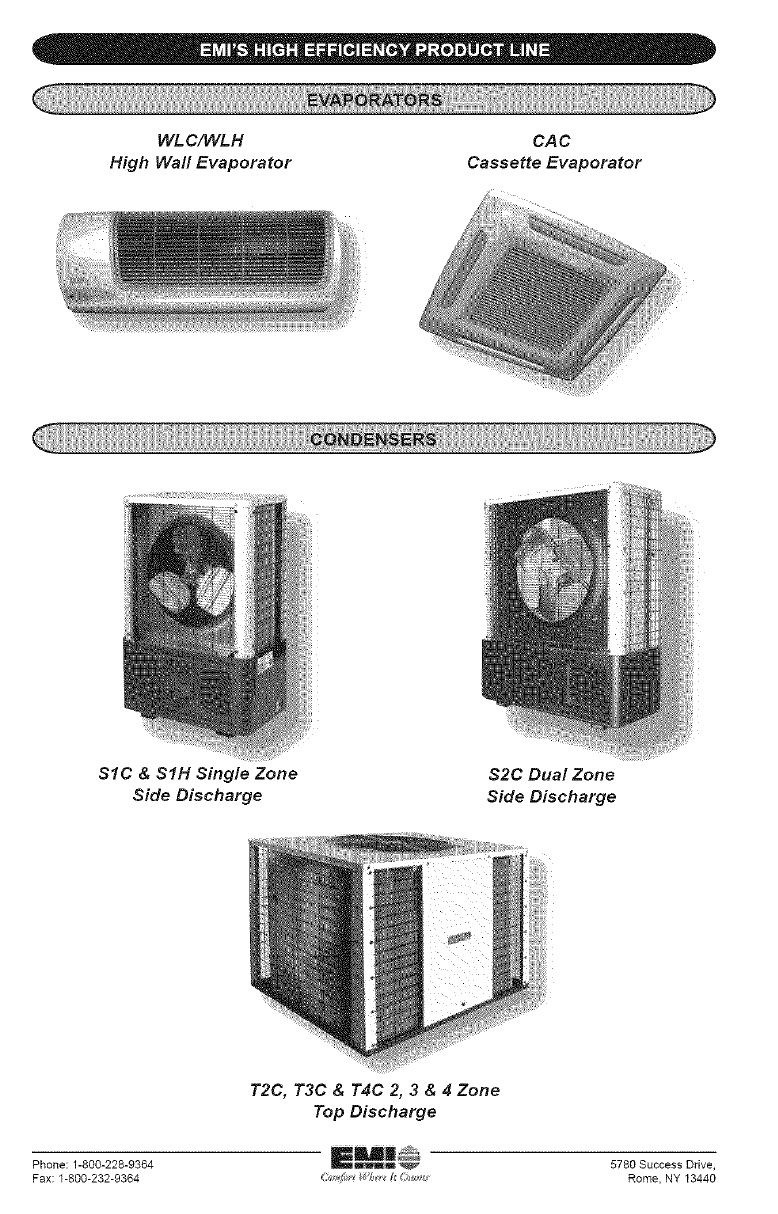
WL C/WLH
High Wall Evaporator
CAC
Cassette Evaporator
SIC & SIH Single Zone
Side Discharge
$2C Dual Zone
Side Discharge
T2C, T3C & T4C 2, 3 & 4 Zone
Top Discharge
Phone: 1-800-228-9364 5780 Success Drive,
Fax: 1-800-232-9364 i_J_ _f_ _i _ Rome, NY 13440
