EMS Technologies Canada A781 A781 Satcom Transceiver User Manual MN 1394 10078
EMS Technologies Canada, Ltd. A781 Satcom Transceiver MN 1394 10078
UserManual.wiki
>
EMS Technologies Canada
>
A781 User Manual
A781 User Manual
Navigation menu
Upload a User Manual
Namespaces
Wiki Guide
HTML
PDF
Info
Views
User Manual
Discussion / Help
Navigation


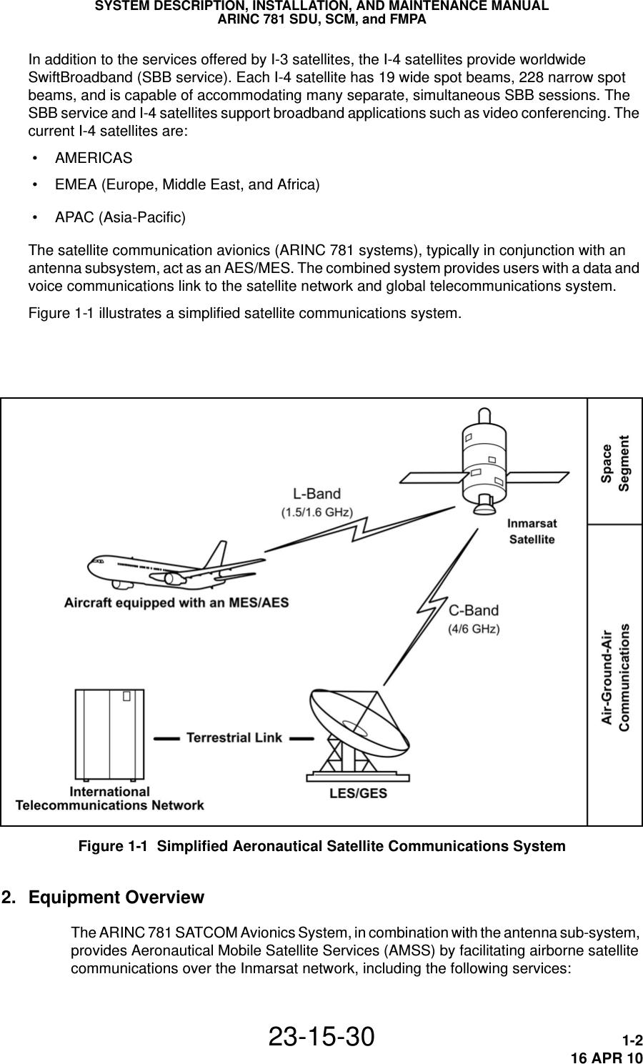
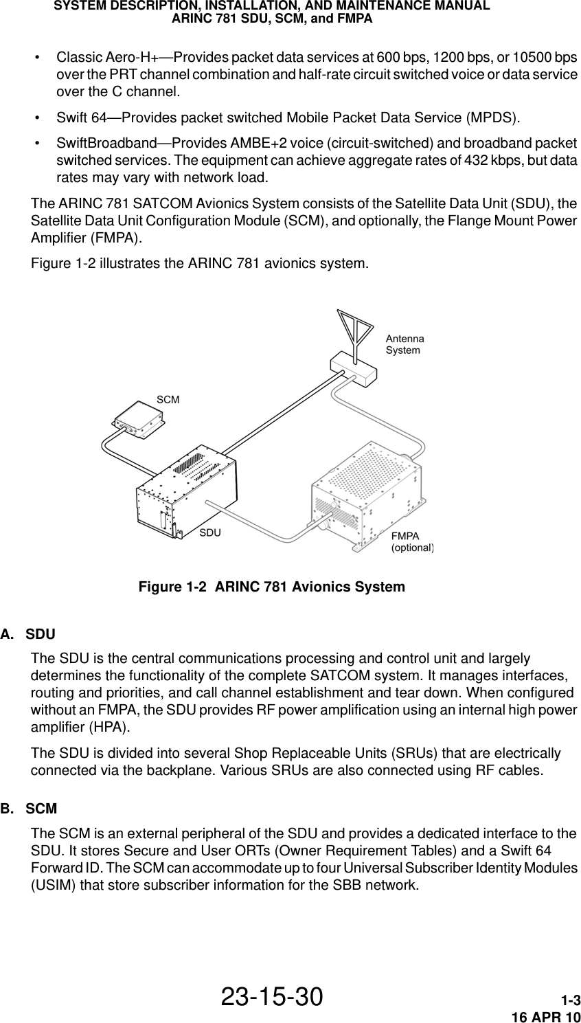
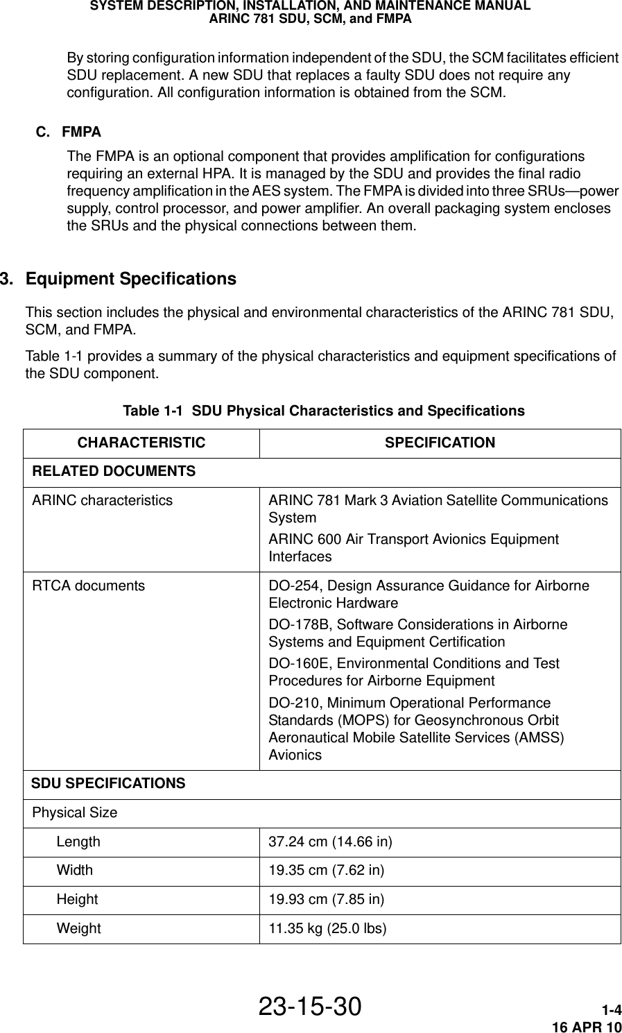
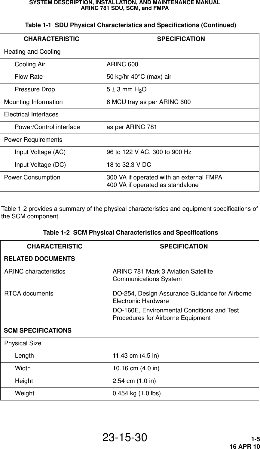
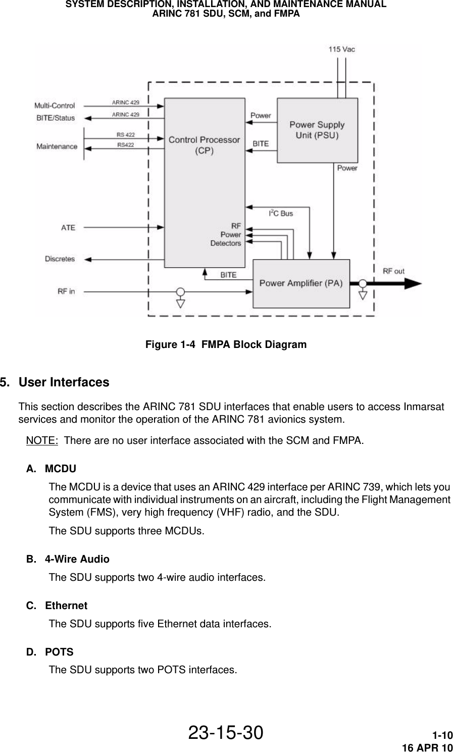
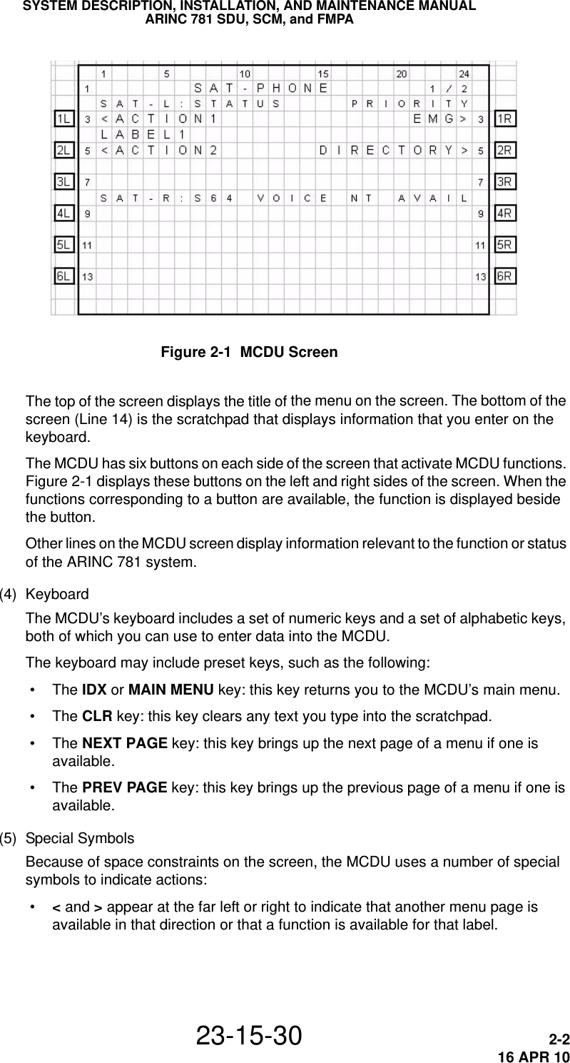
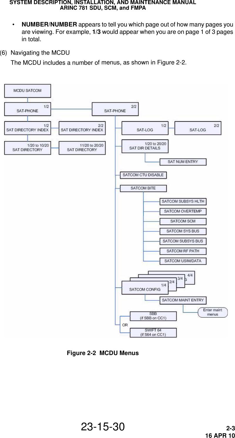
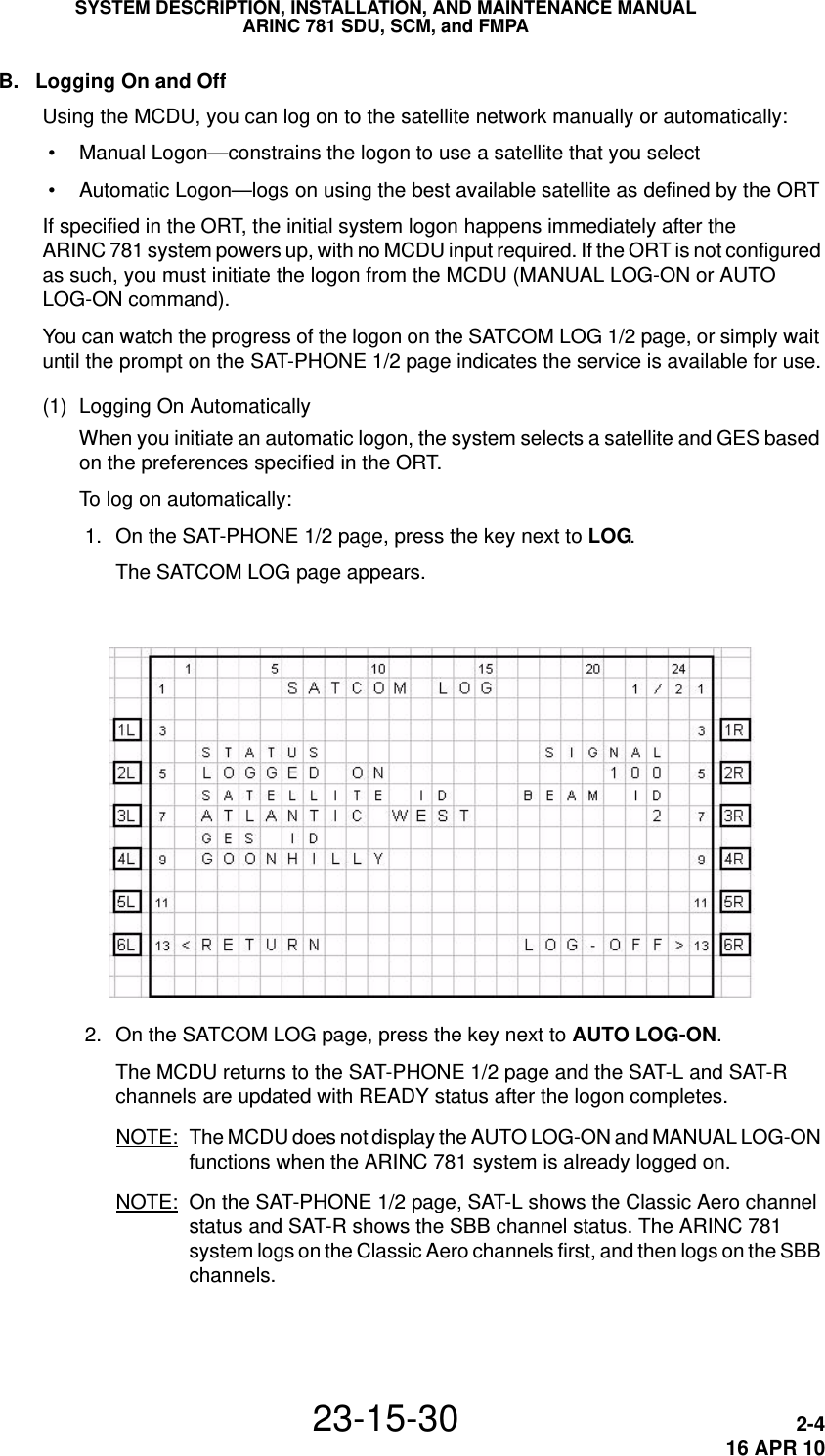
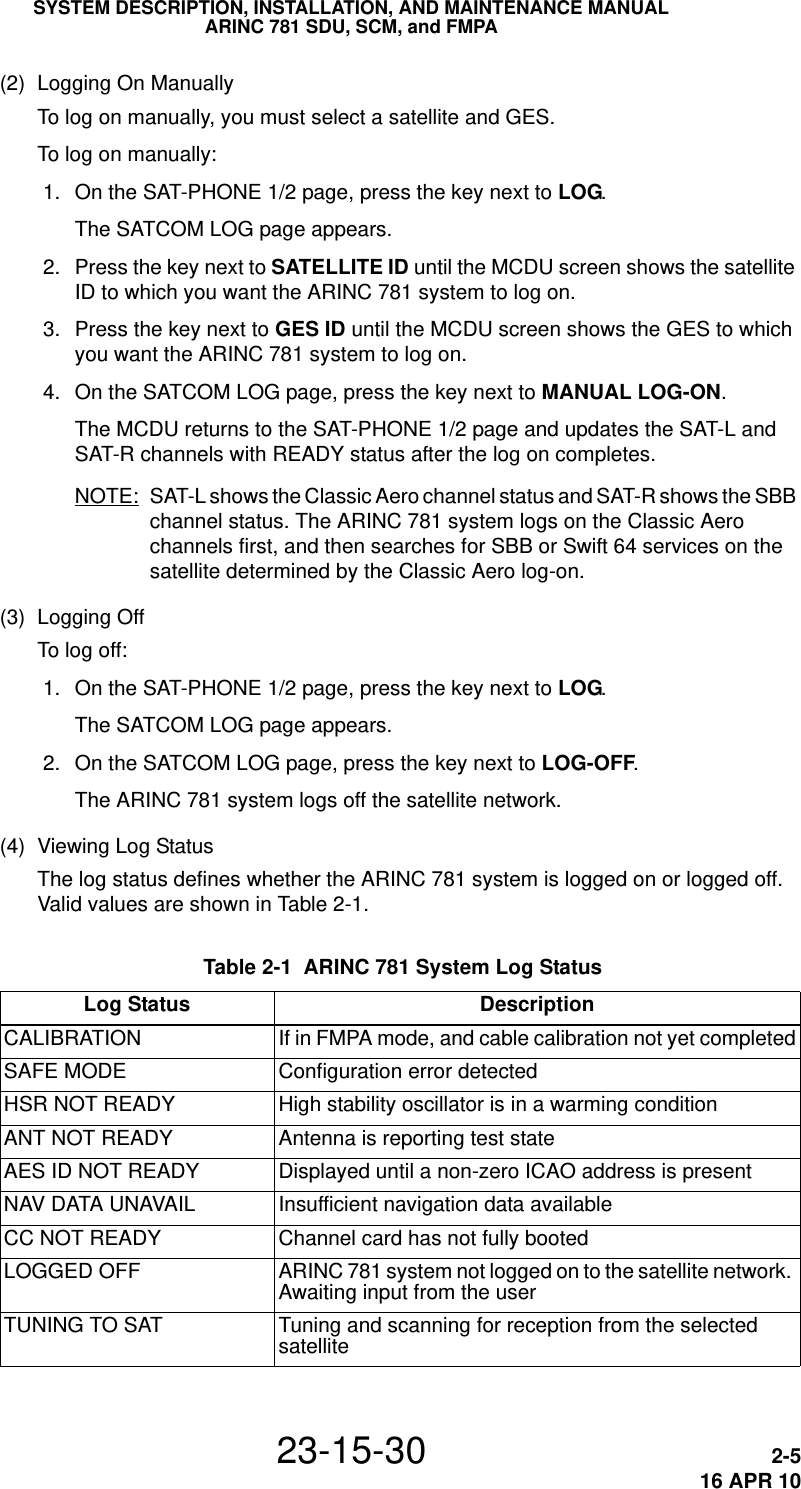
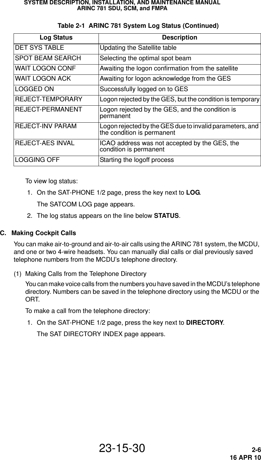
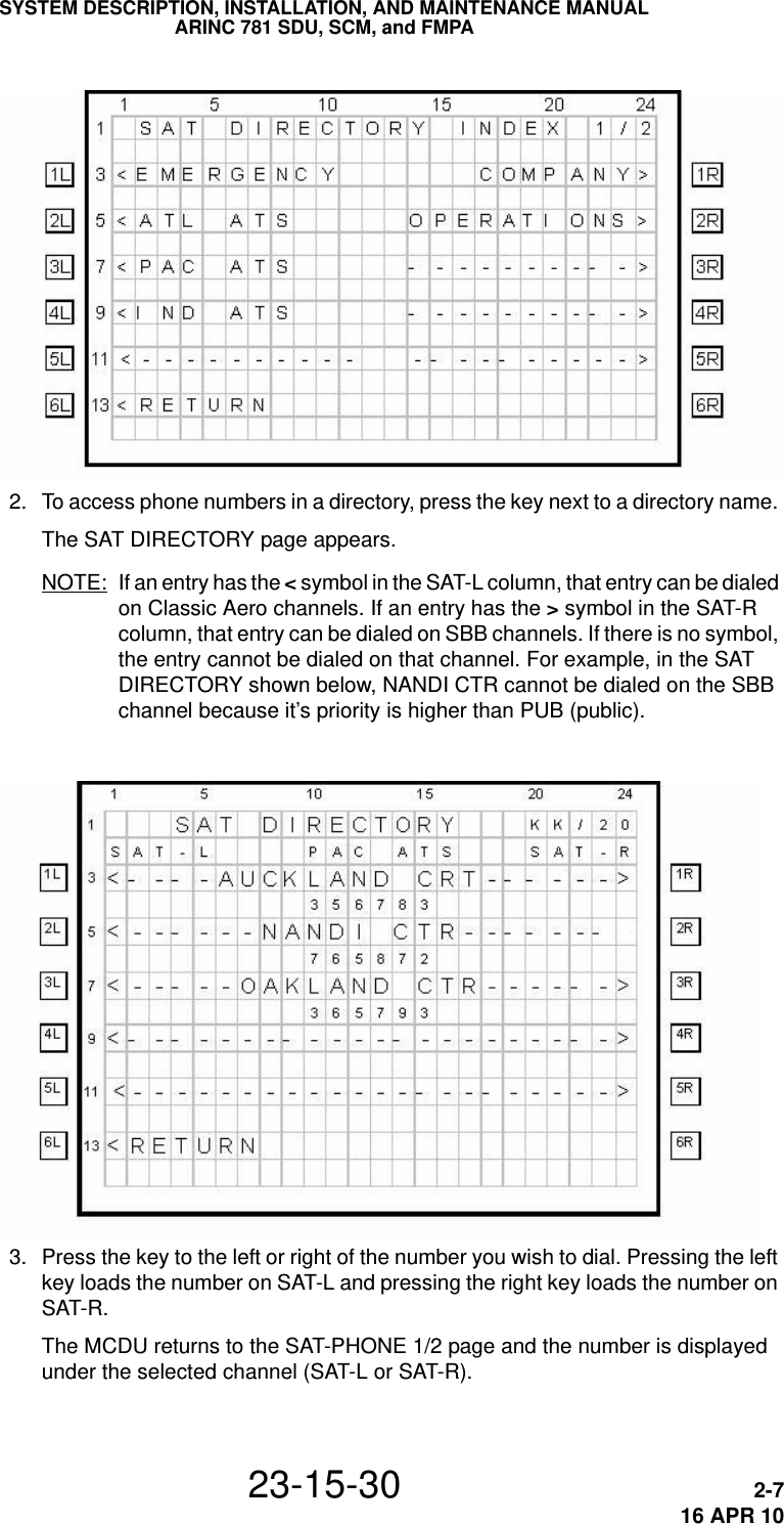
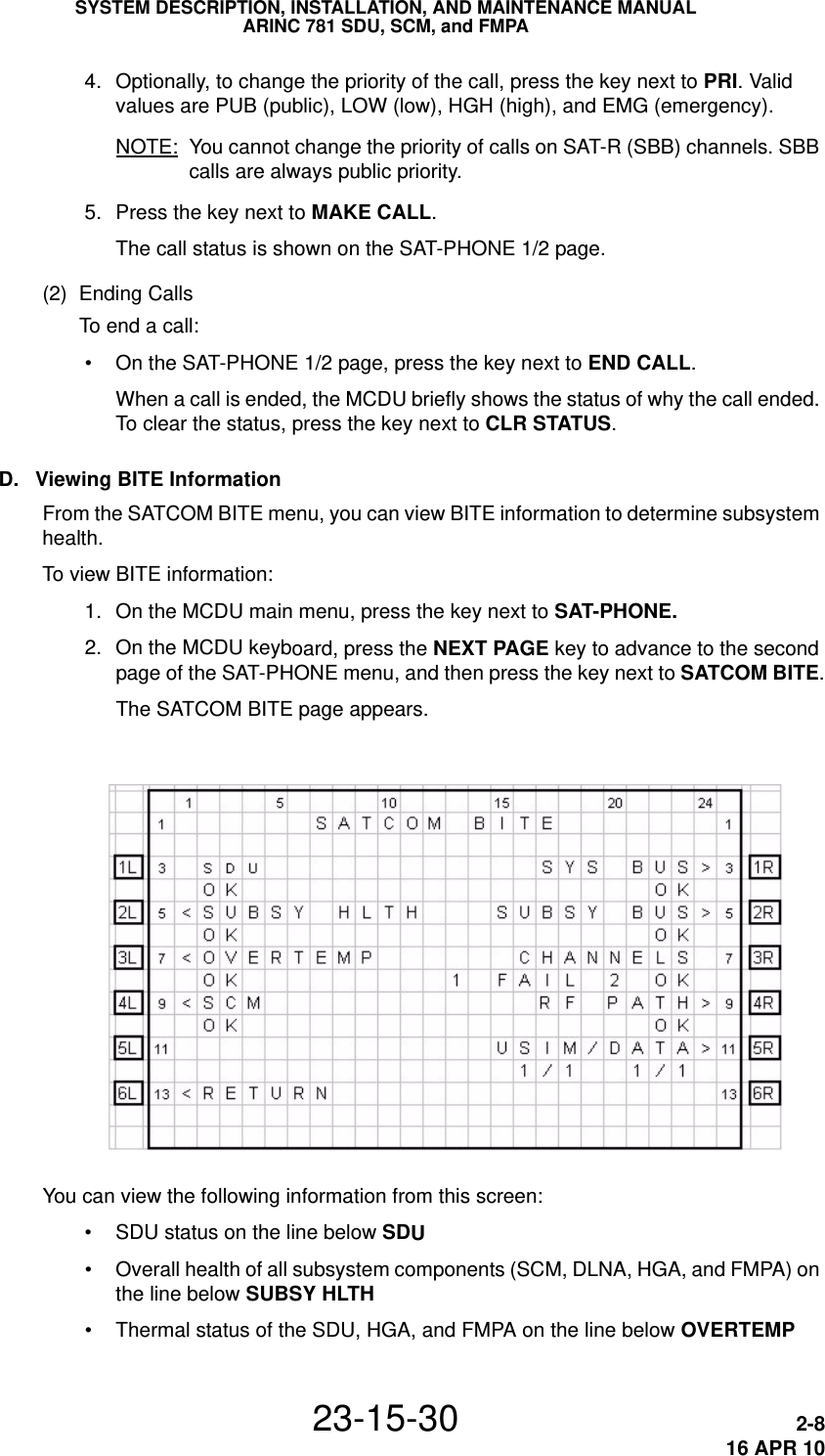


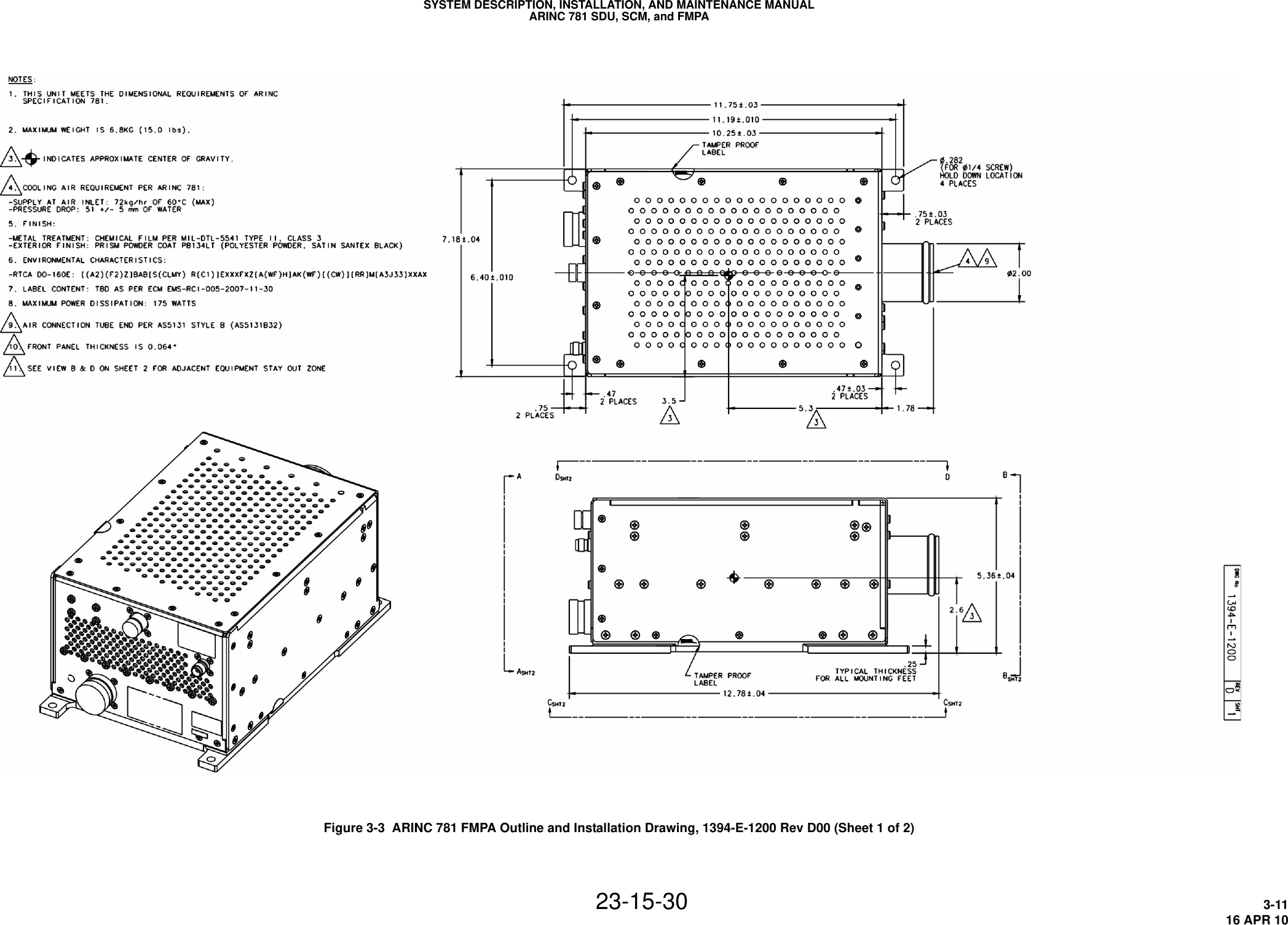

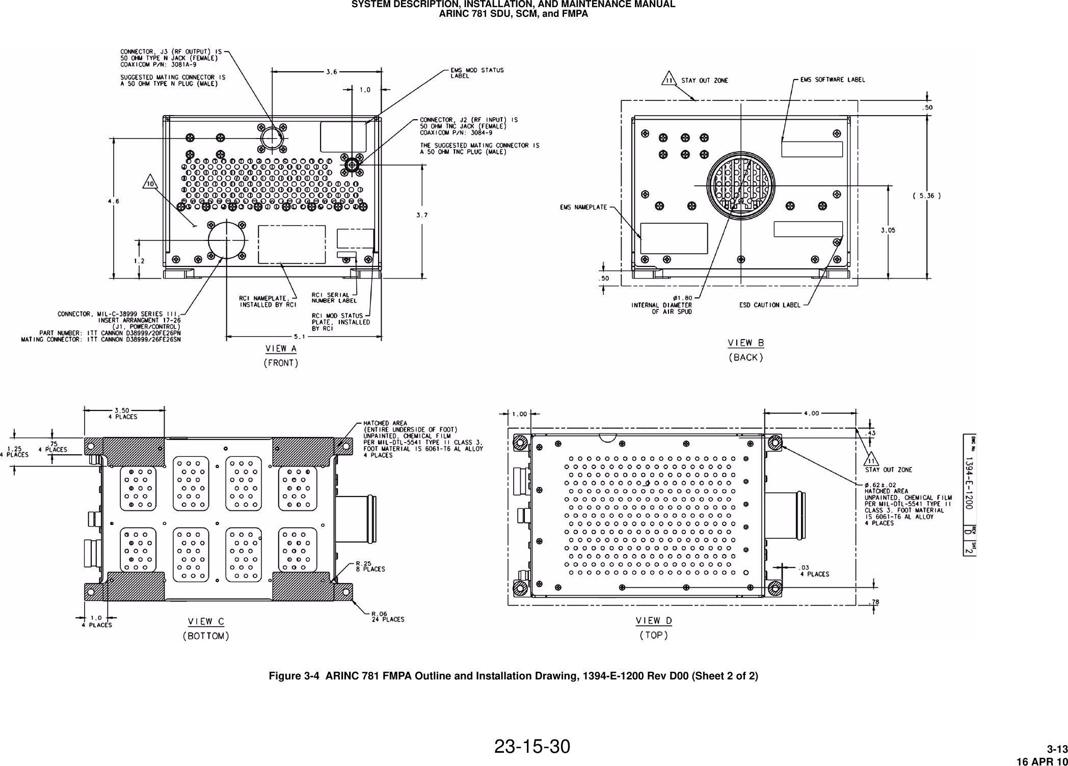

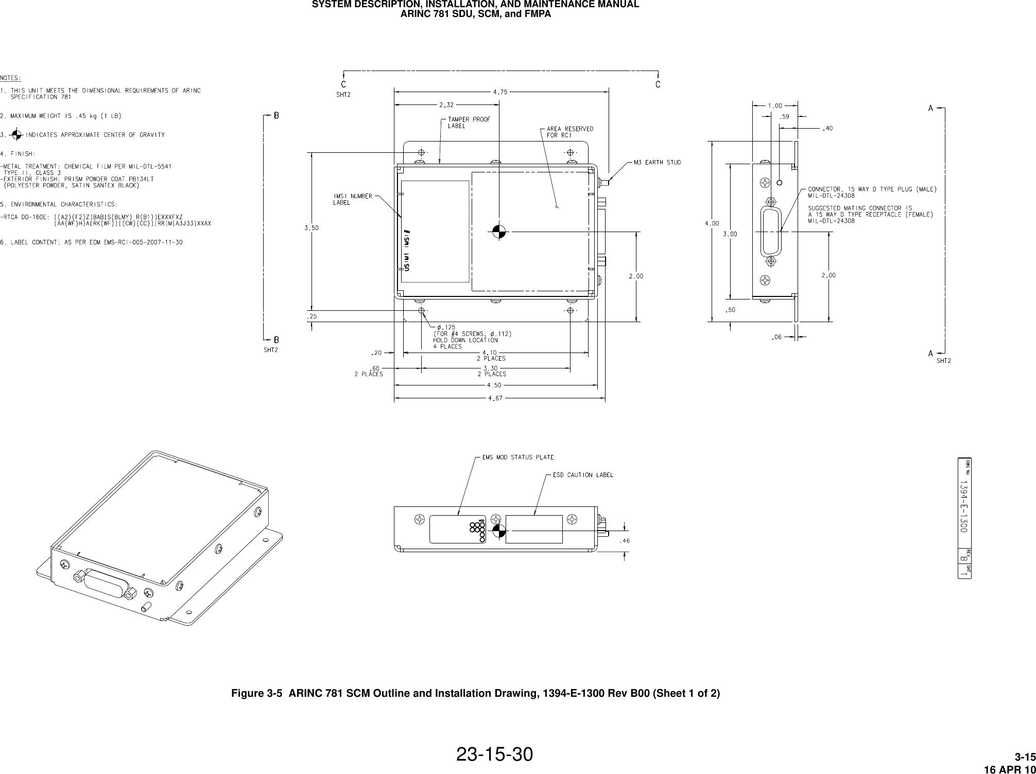

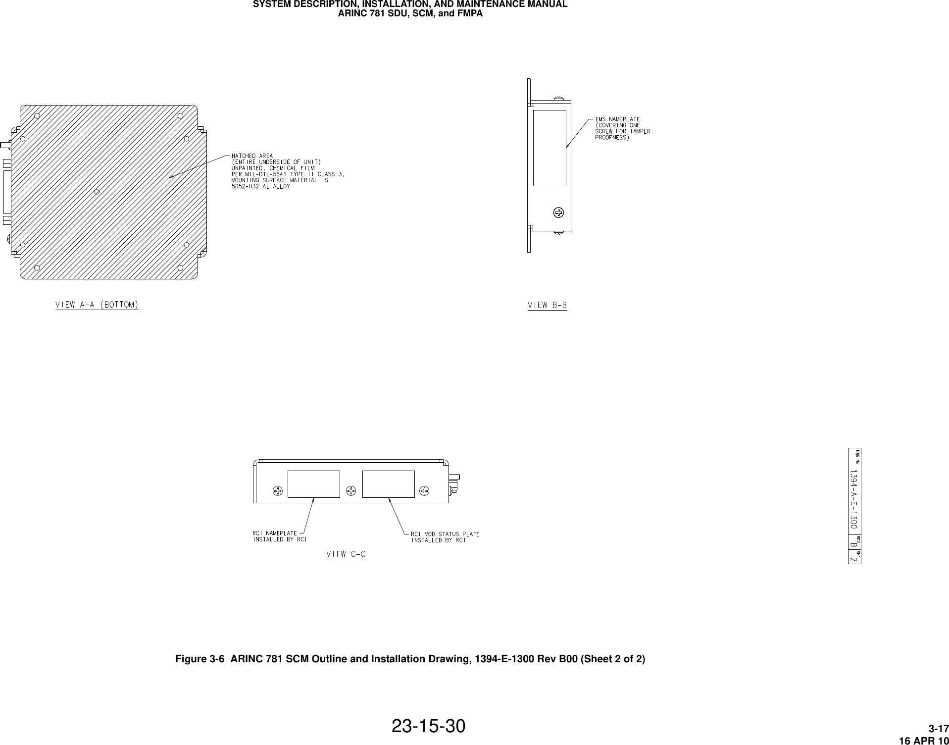

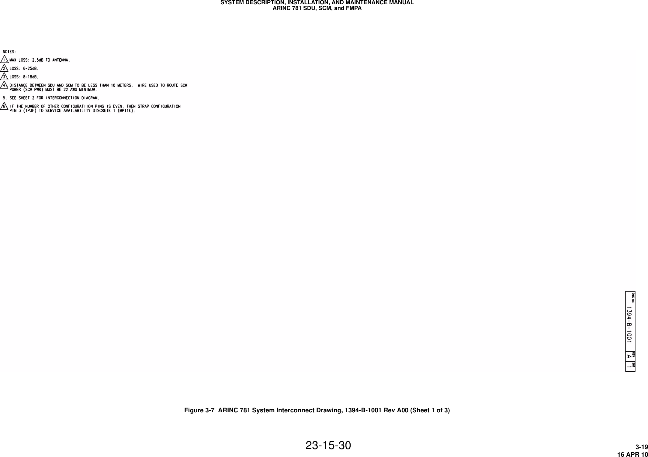

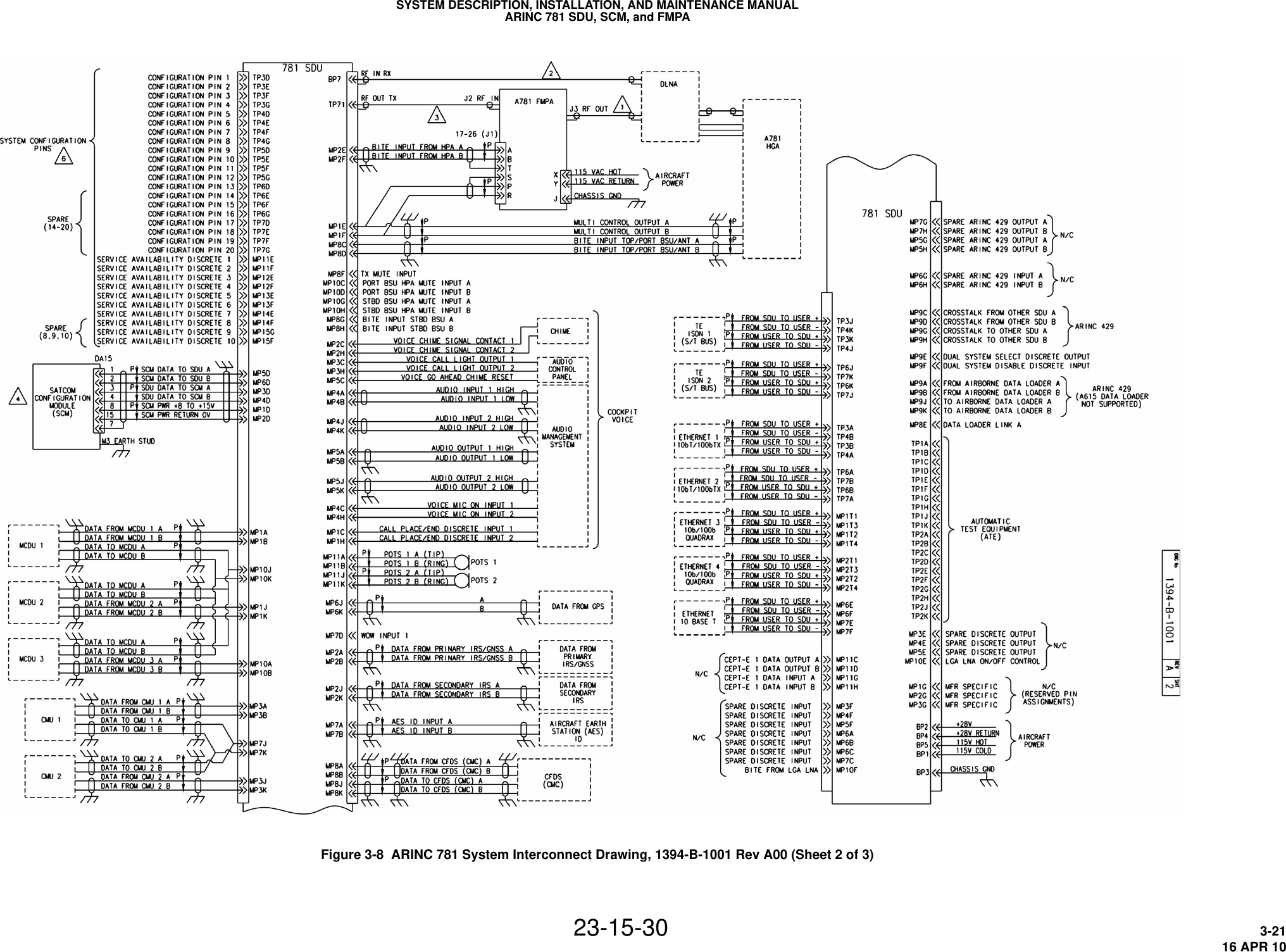

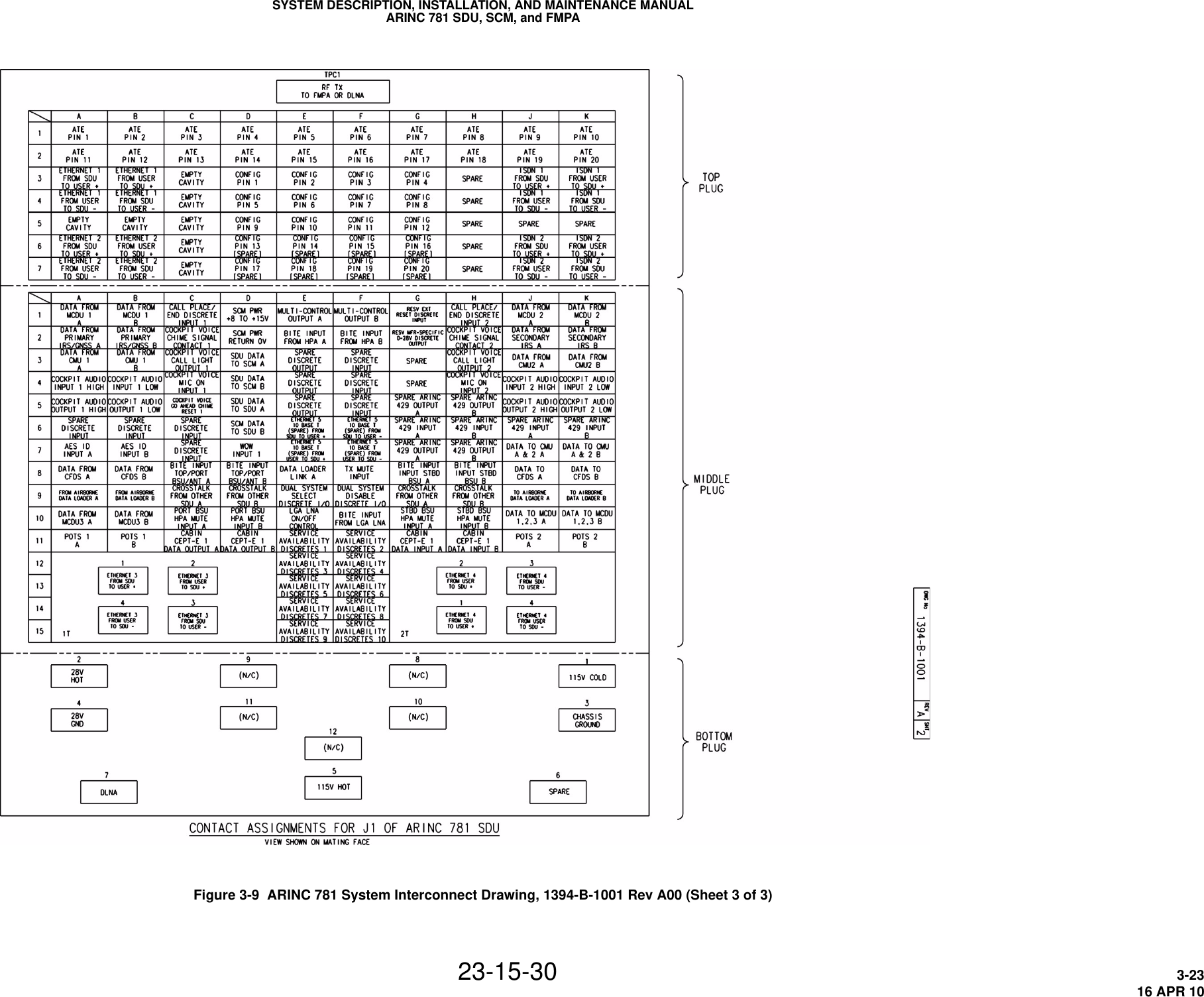

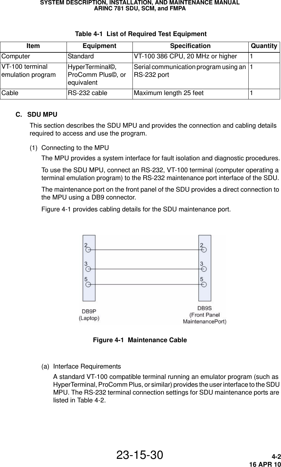
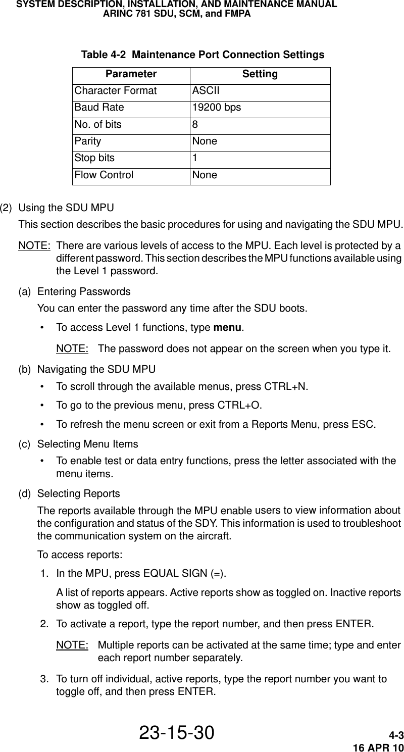
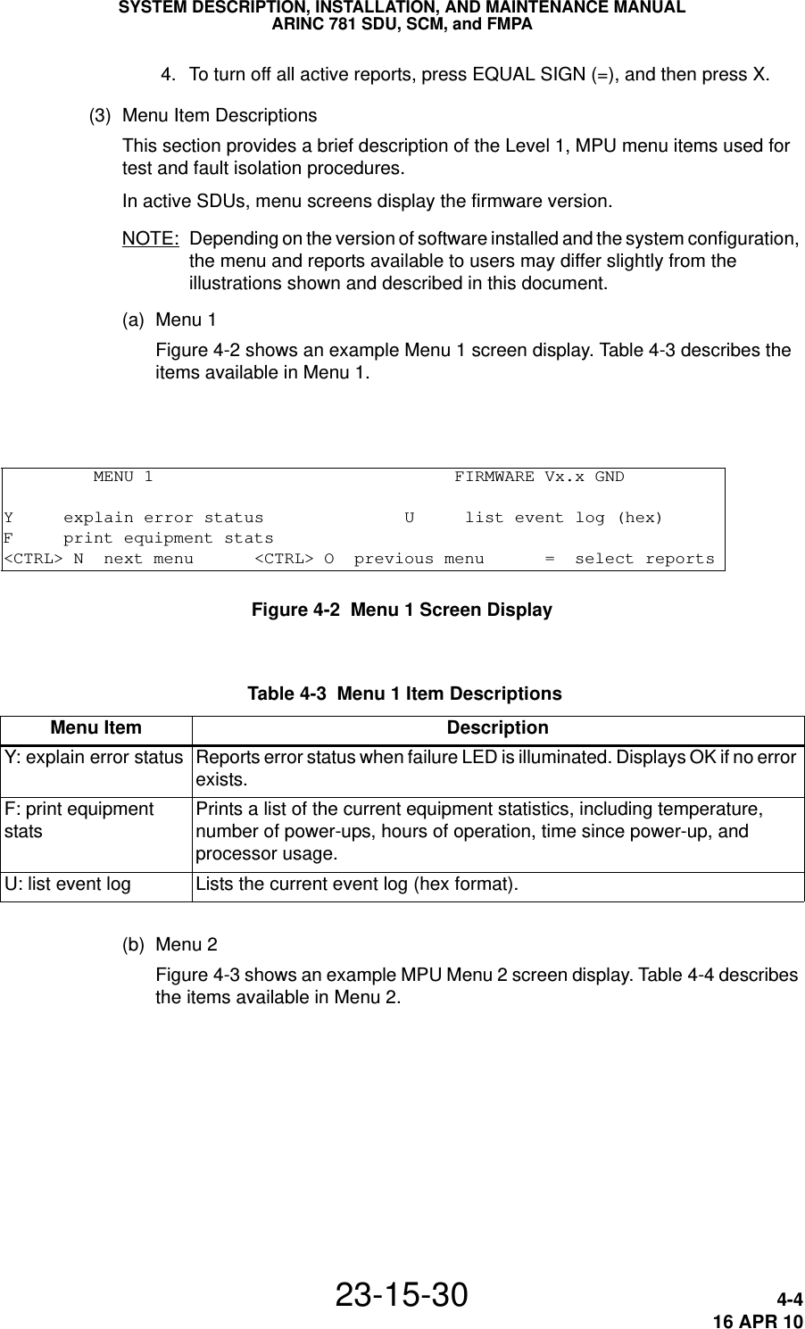
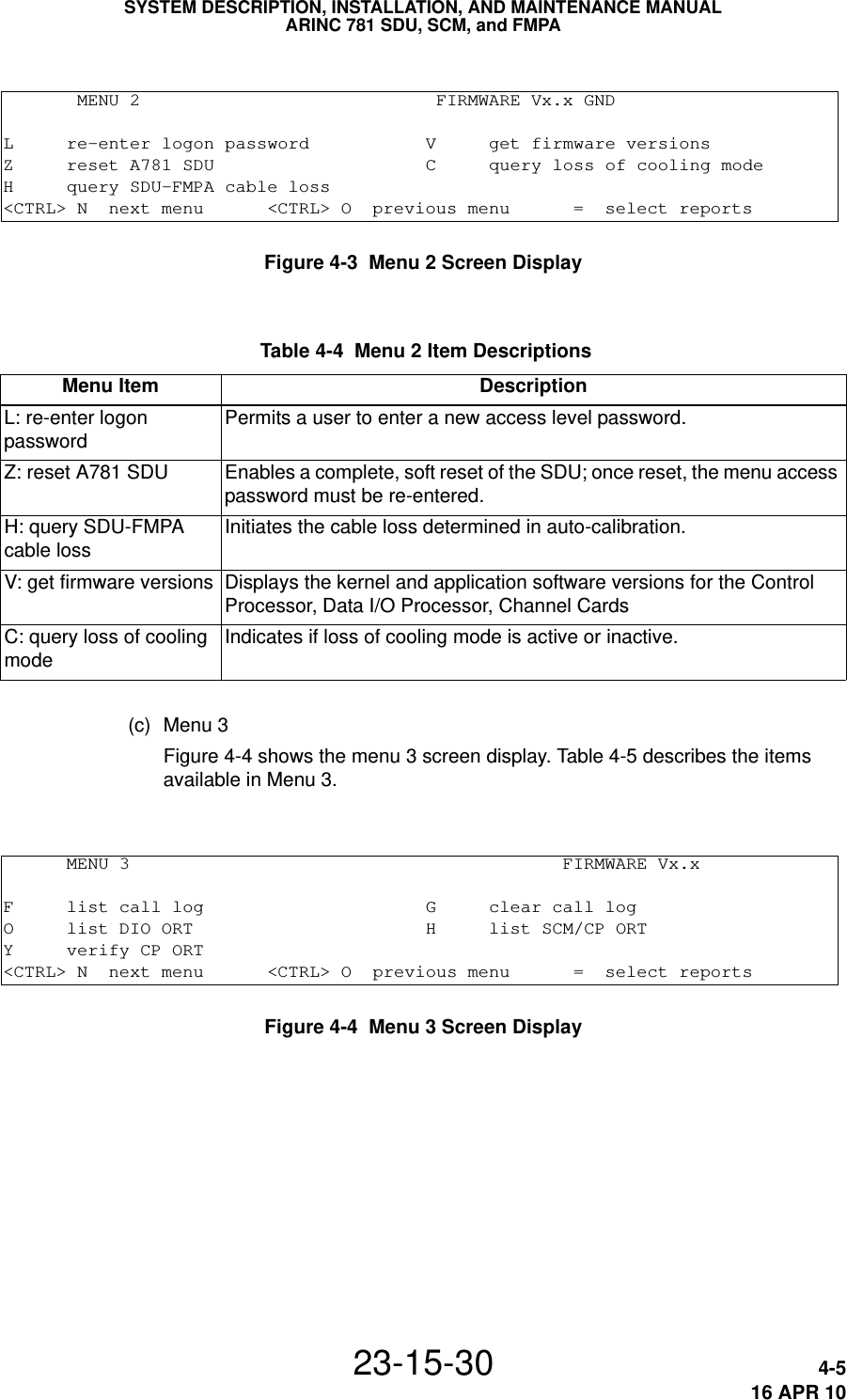
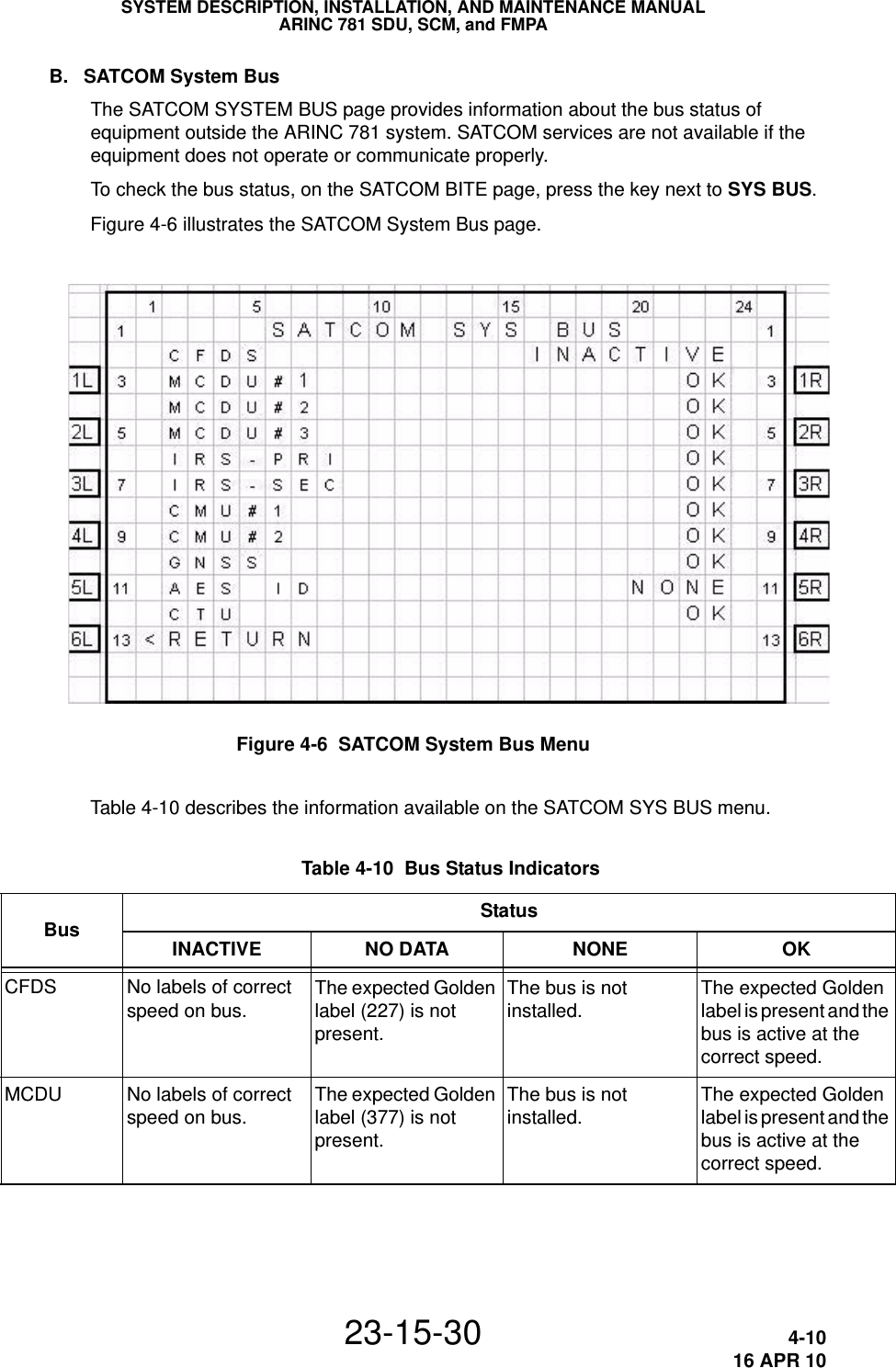
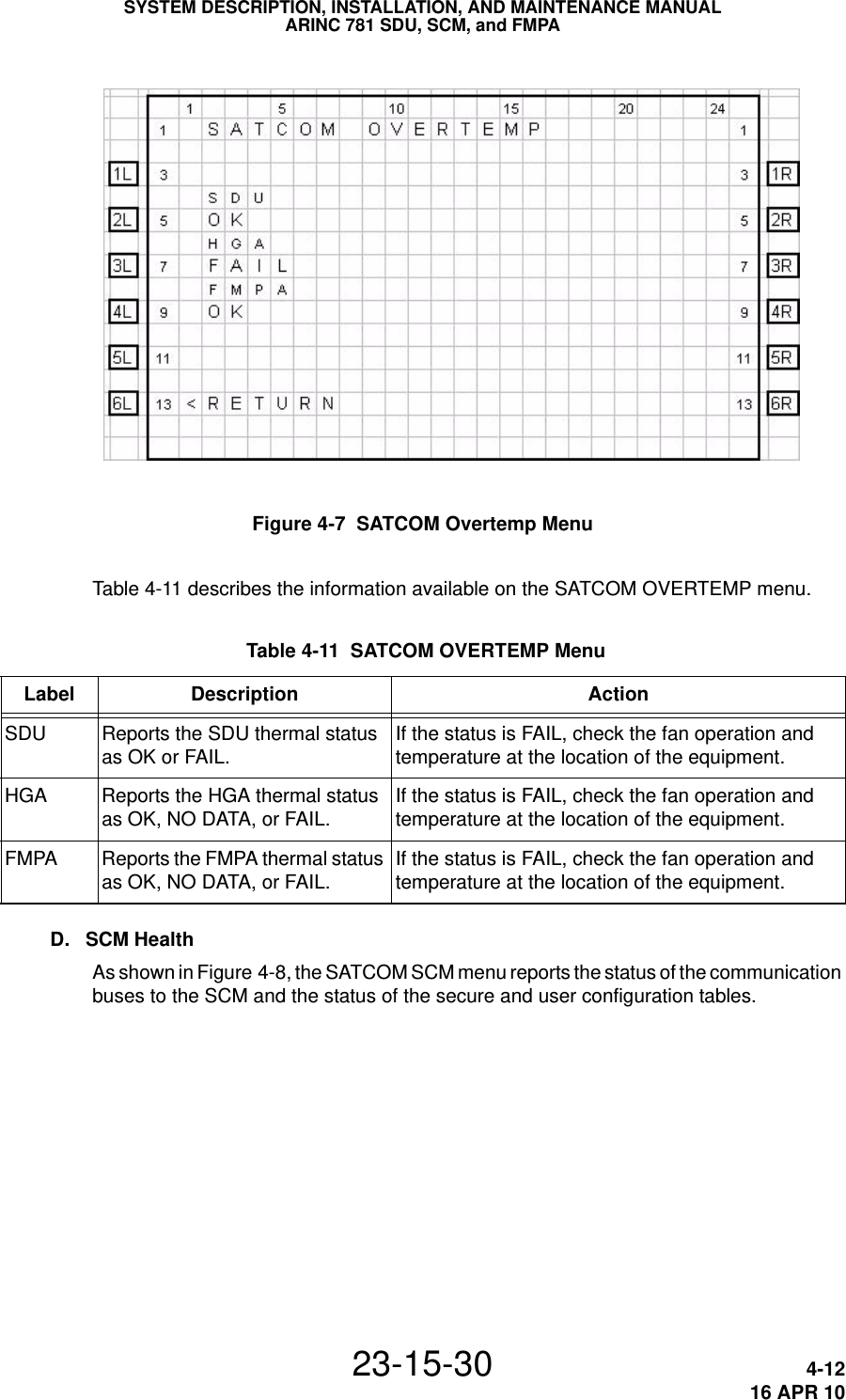
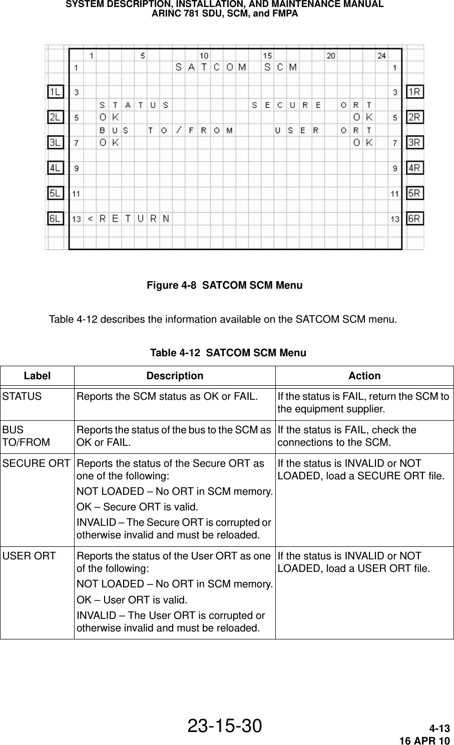
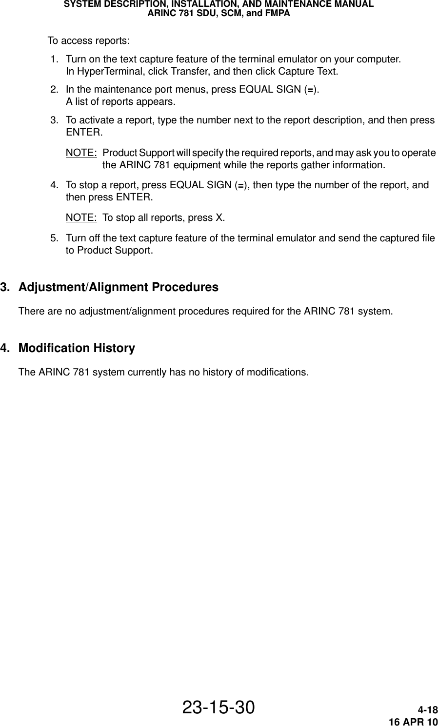
![SYSTEM DESCRIPTION, INSTALLATION, AND MAINTENANCE MANUALARINC 781 SDU, SCM, and FMPA23-15-30 5-116 APR 10MAINTENANCE AND REPAIRThis section provides maintenance and repair information for the ARINC 781 system, including the following sections: • Maintenance • Repair • Instructions for Continued Airworthiness • Visual Inspection and Check1. MaintenanceThe ARINC 781 system does not require routine maintenance.2. RepairIf functional problems occur, the SDU BITE identifies the faulty LRU.As per continued airworthiness instructions, if an SDU, SCM, or FMPA is inoperative, use the Standard Practices Chapter of the Aircraft Maintenance Manual to: • remove the unit • secure cables and wiring • collar applicable switches and circuit breakers, and placard them as “inoperative”Before flight, revise the equipment list and weight and balance data as applicable, and record the removal of the unit in the log book [refer to section 91.213 of the FAR or the aircraft’s minimum equipment list (MEL)].All repairs must be performed at the equipment supplier factory.3. Instructions for Continued AirworthinessPeriodic inspections of the mechanical and electrical interfaces of the ARINC 781 system components to the aircraft should be completed as defined by the governing airworthiness body’s Instructions for Continued Airworthiness (ICA) for the installation (for example, Transport Canada, the FAA, the EASA).Installation of the ARINC 781 SATCOM Avionics System on an aircraft by Supplemental Type Certificate (STC) obligates the aircraft operator to include the maintenance information supplied by this manual in the operator’s Aircraft Maintenance manual and the operator’s Aircraft Scheduled Maintenance Program. This section provides the special instructions and maintenance requirements for continued airworthiness of the ARINC 781 system.](https://usermanual.wiki/EMS-Technologies-Canada/A781/User-Guide-1291613-Page-89.png)