EMS Technologies Canada HSD-440 eNfusion HSD-440 Aeronautical Satcom Transceiver User Manual MN 1252 33077
EMS Technologies Canada, Ltd. eNfusion HSD-440 Aeronautical Satcom Transceiver MN 1252 33077
UserManual.wiki
>
EMS Technologies Canada
>
HSD 440 User Manual
HSD-440 Users Manual
Navigation menu
Upload a User Manual
Namespaces
Wiki Guide
HTML
PDF
Info
Views
User Manual
Discussion / Help
Navigation

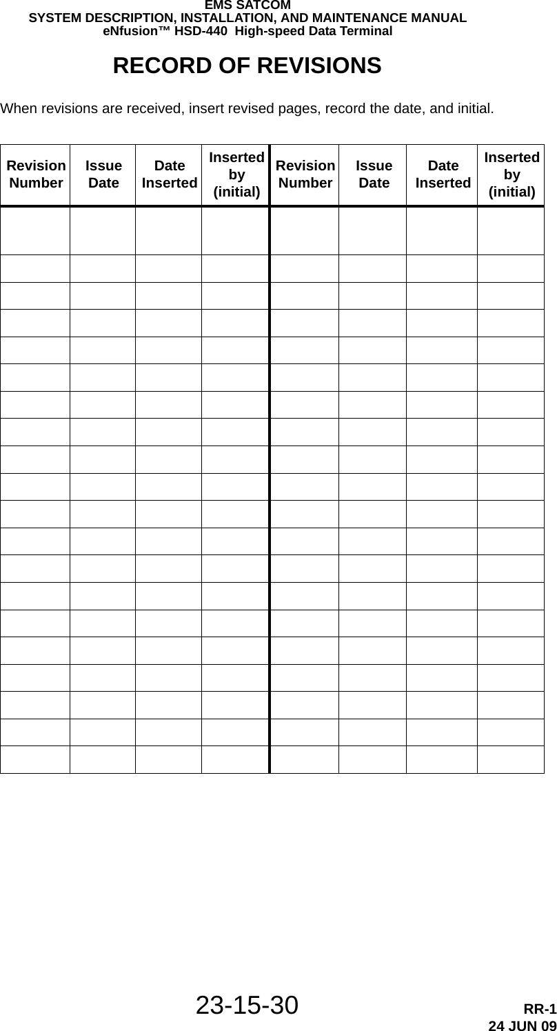


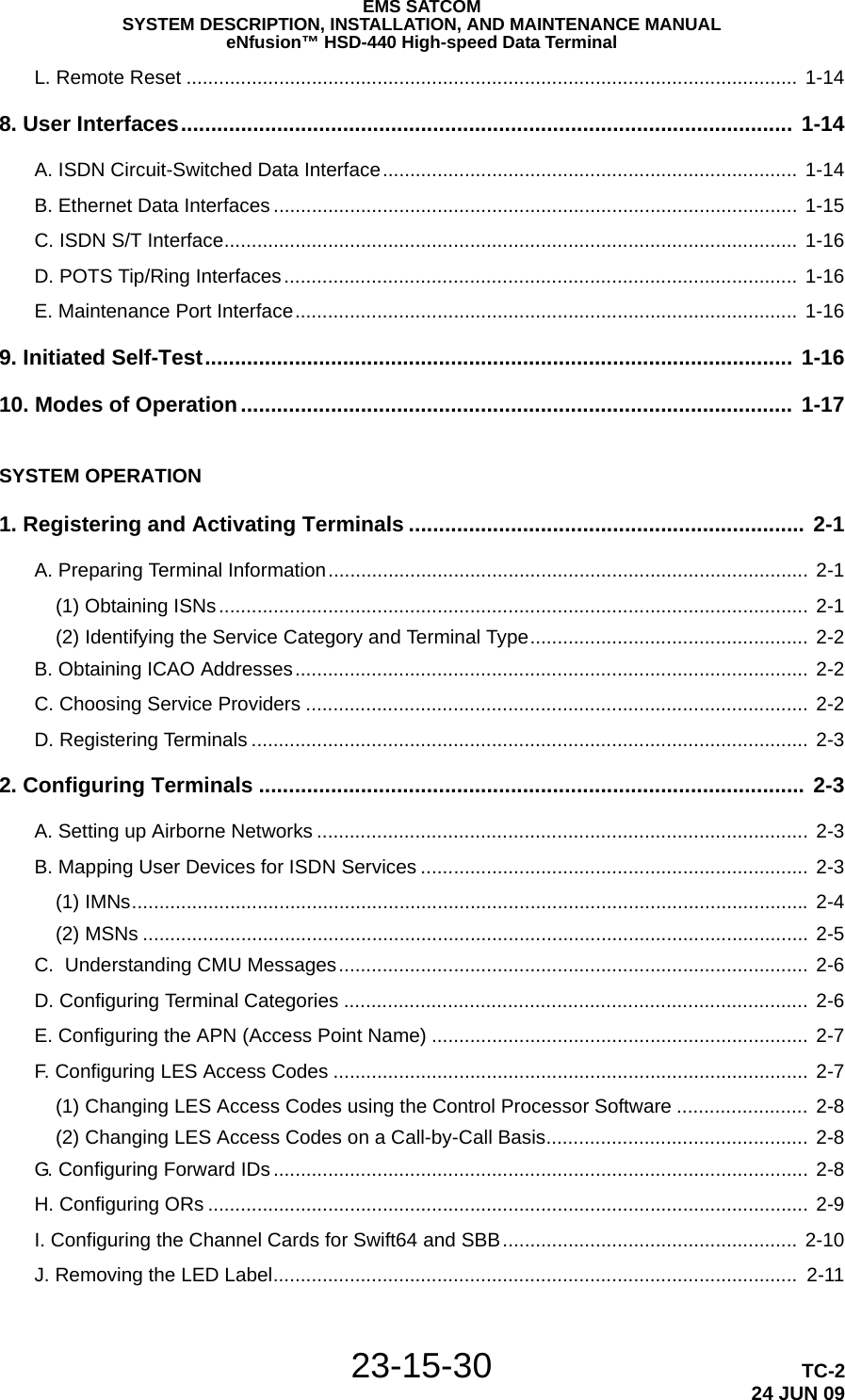
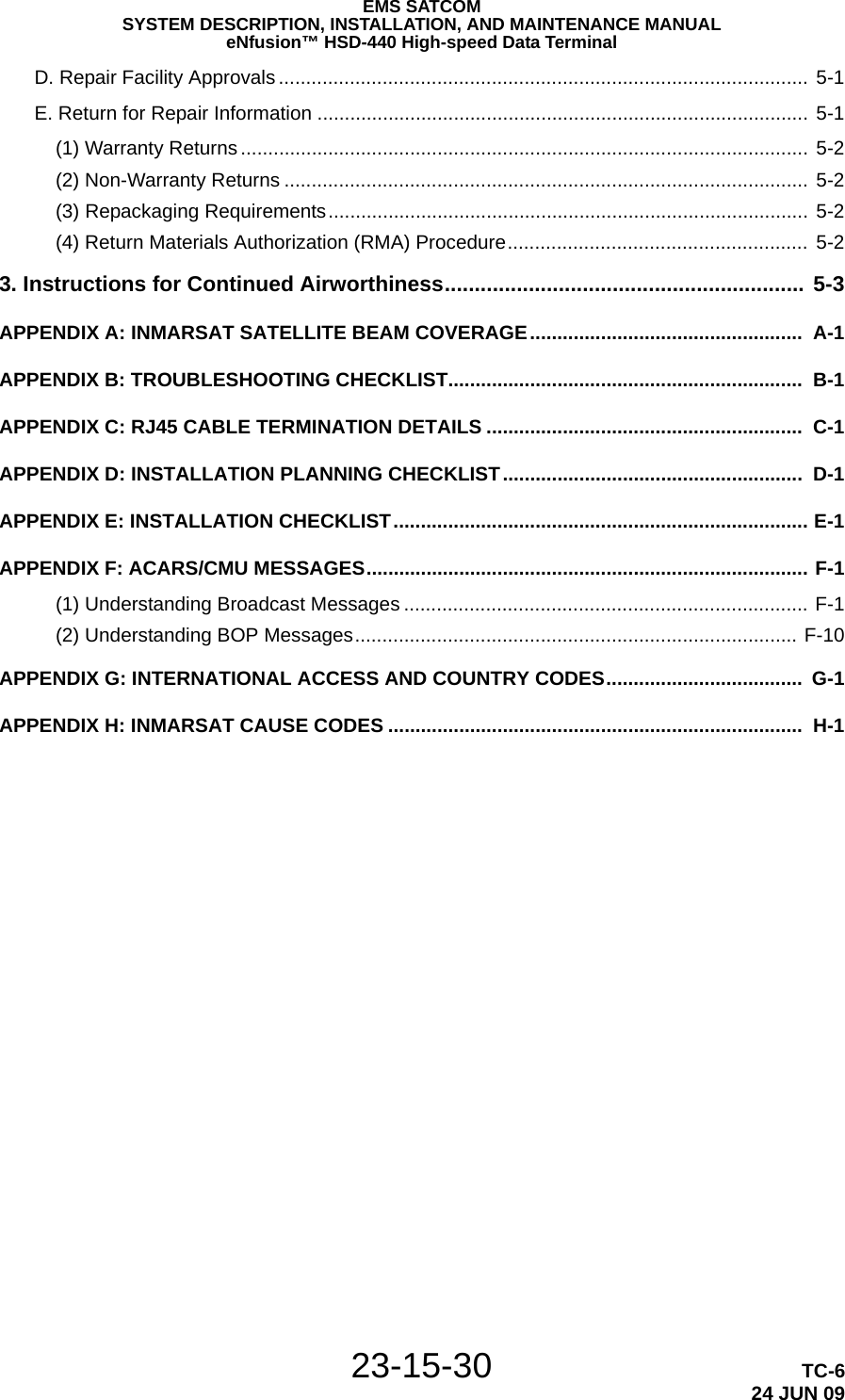

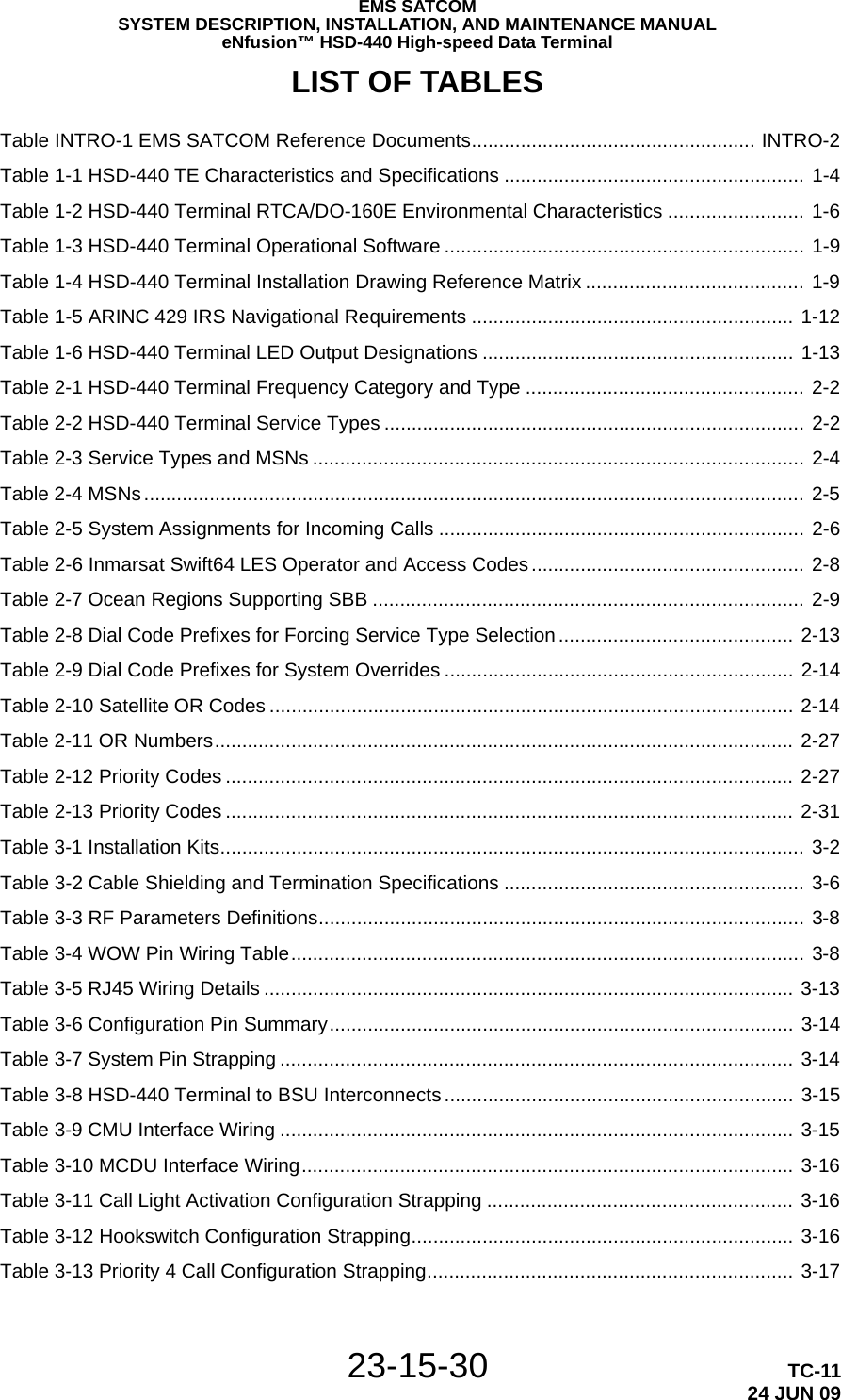
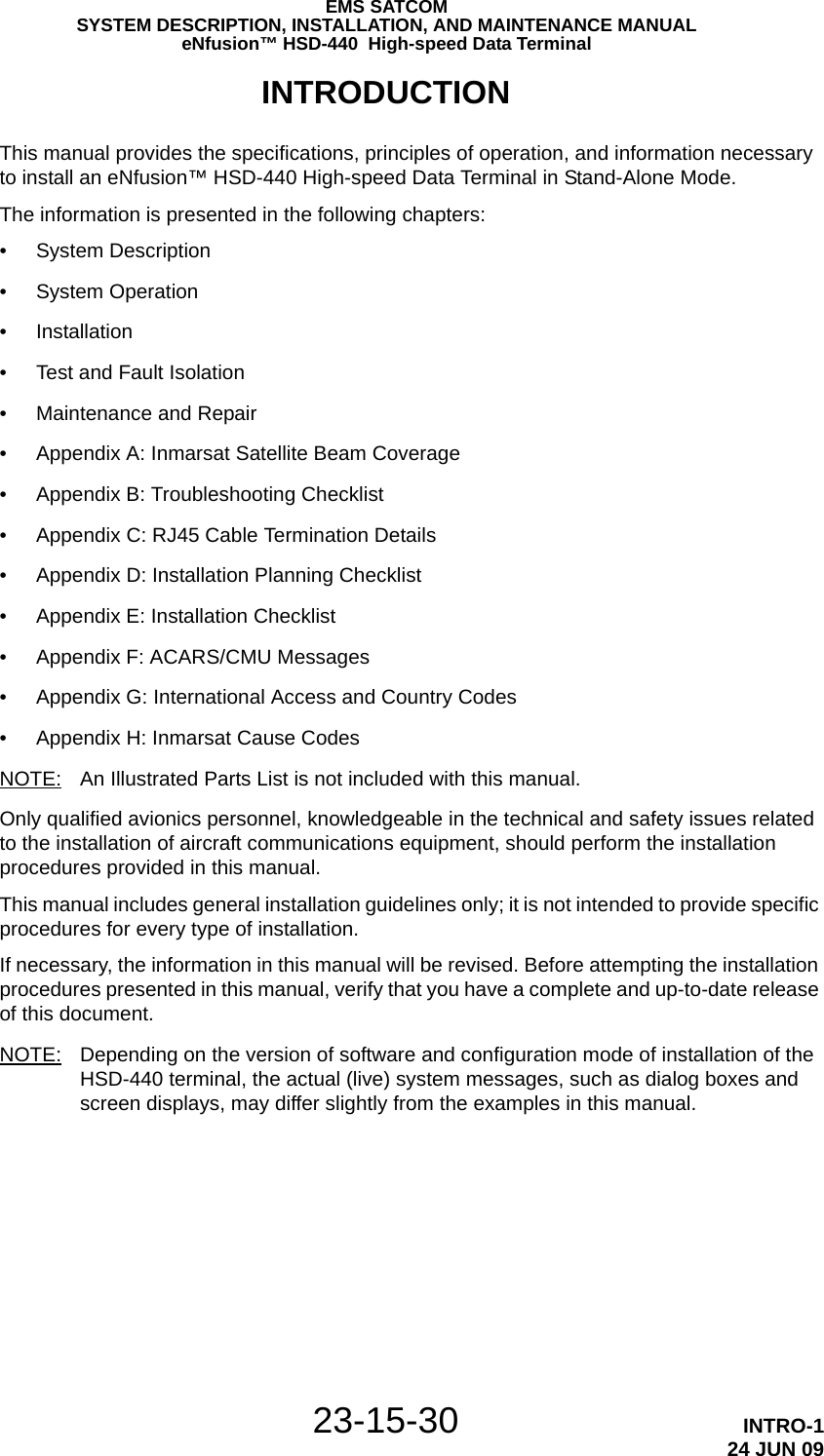
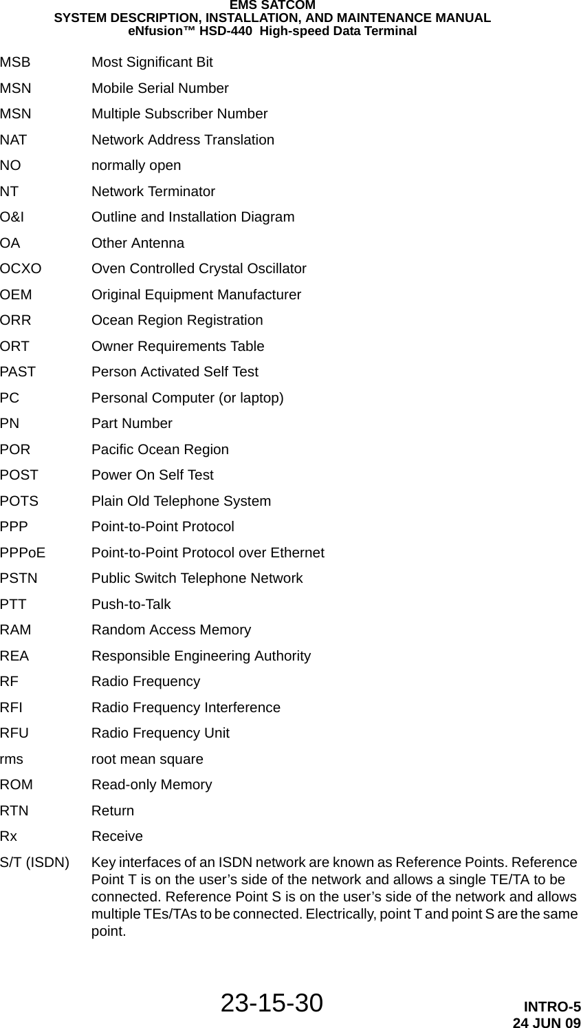
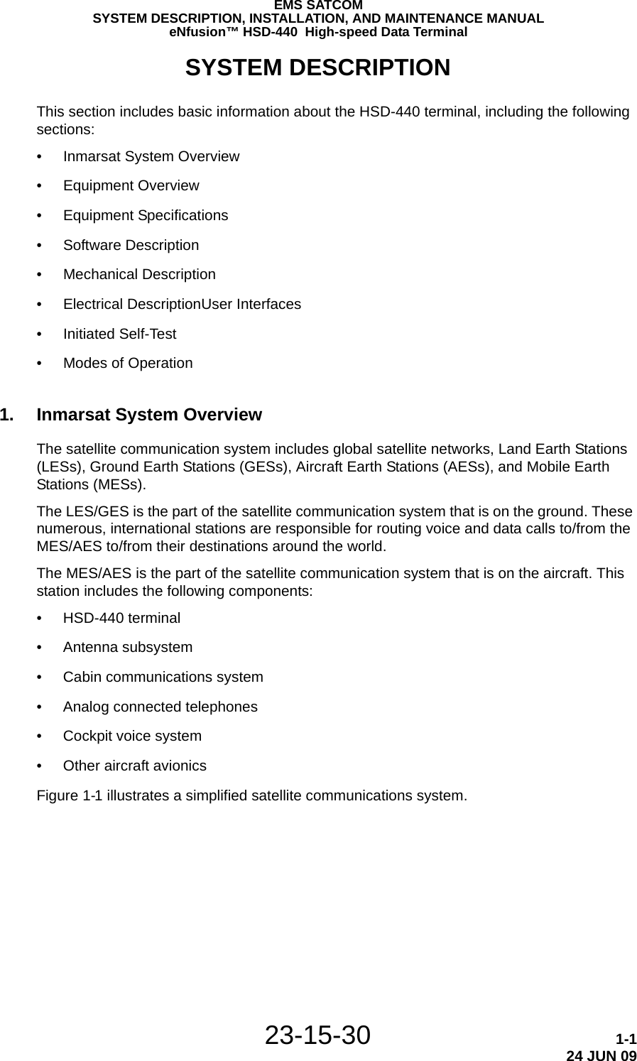
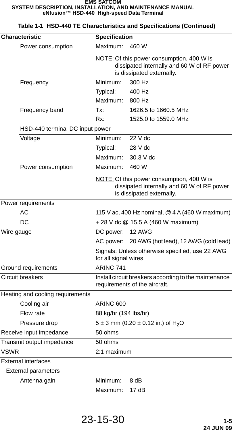
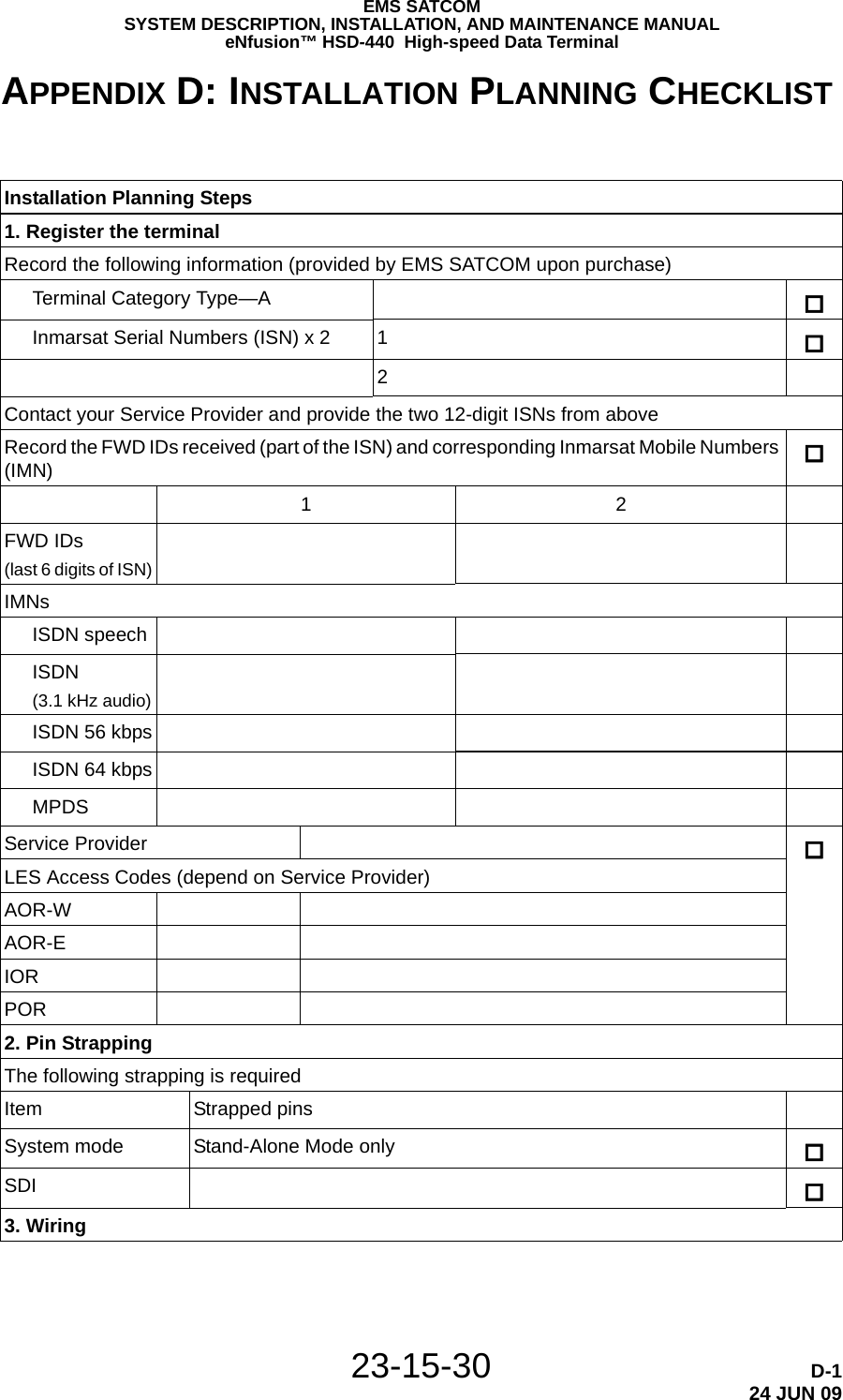
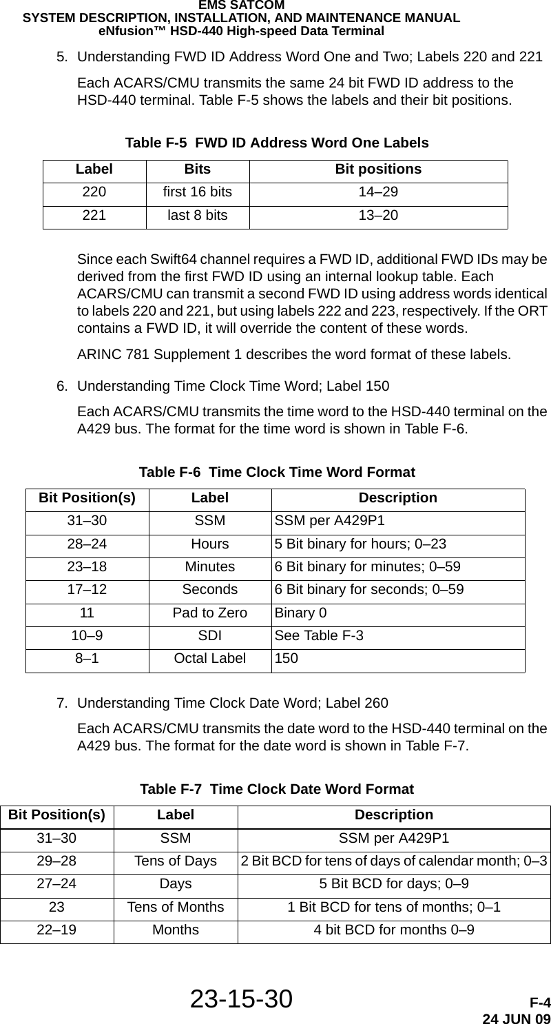
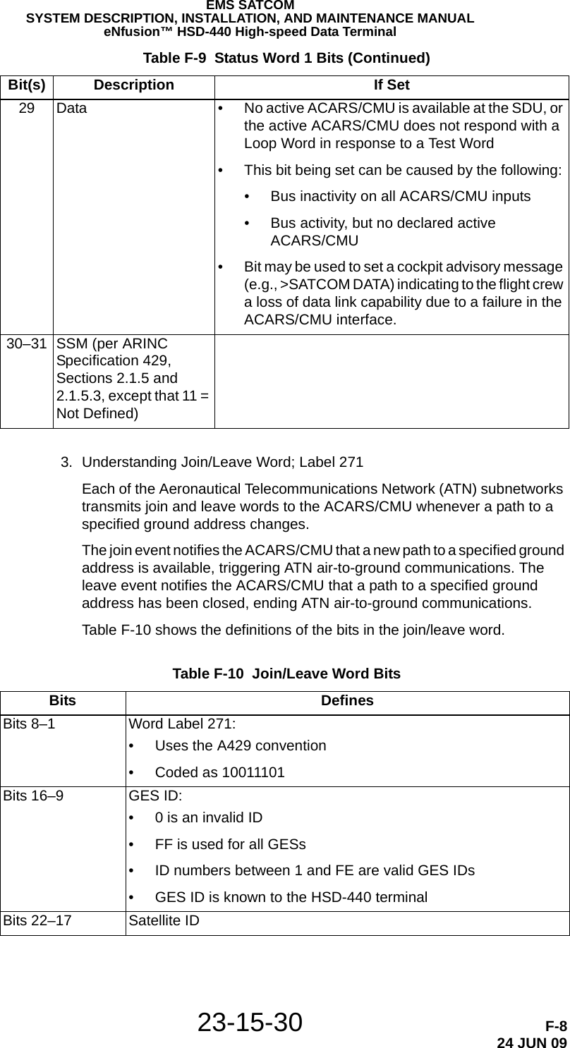
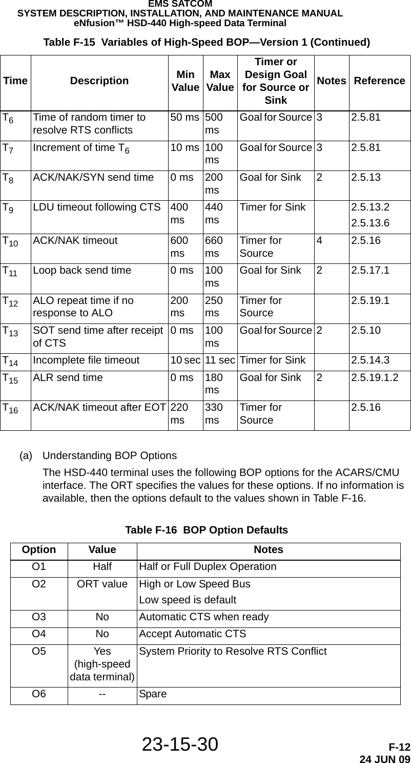
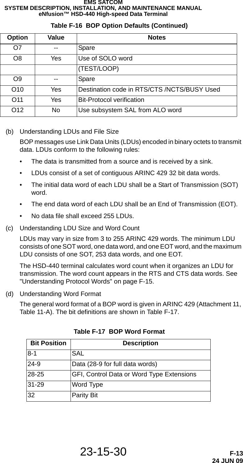
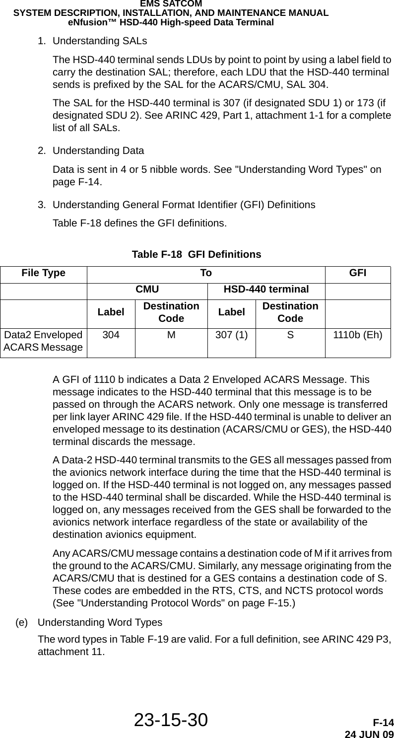
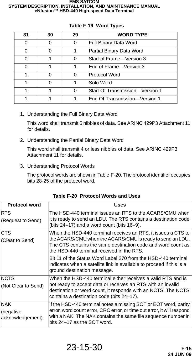
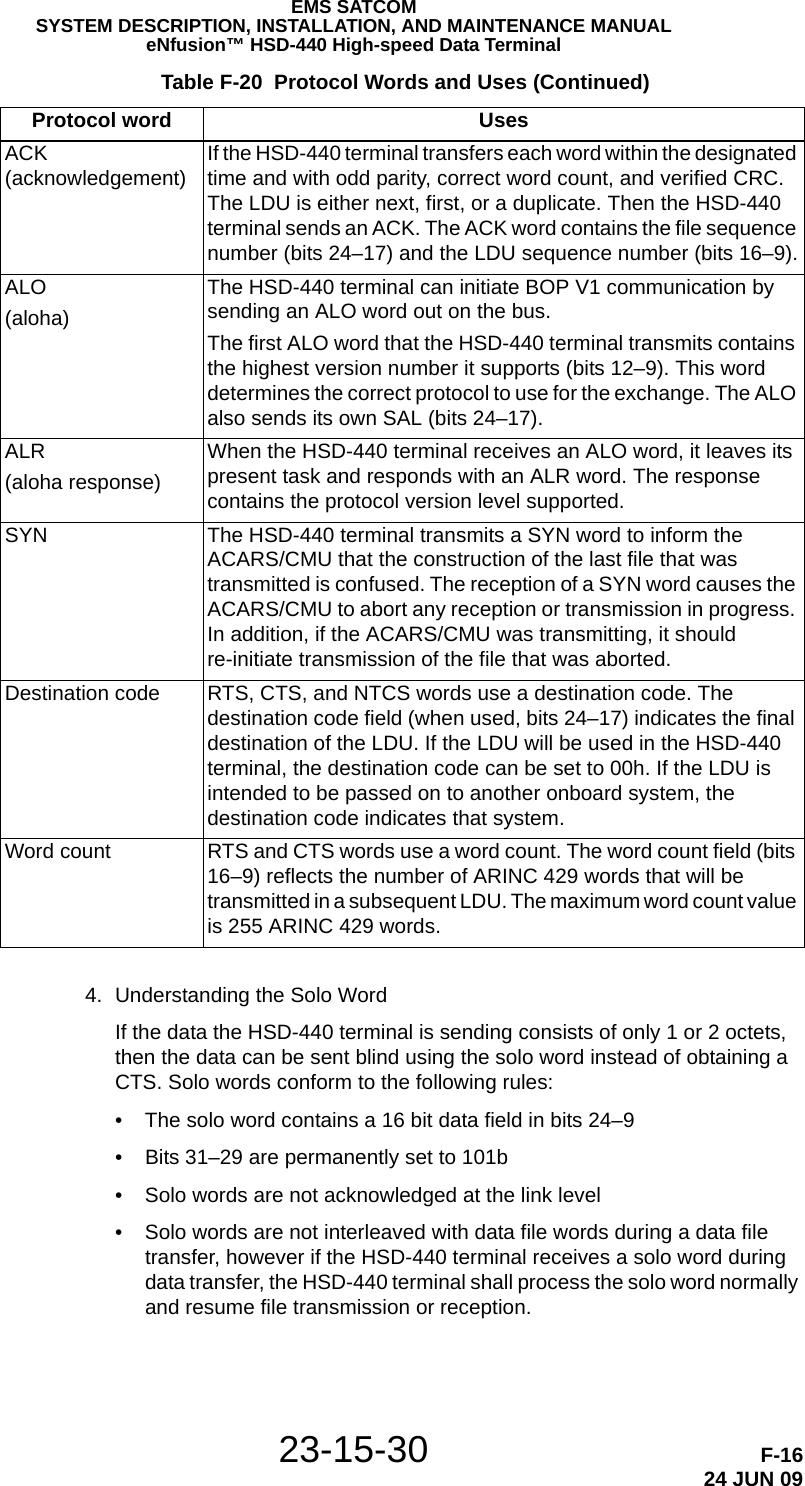
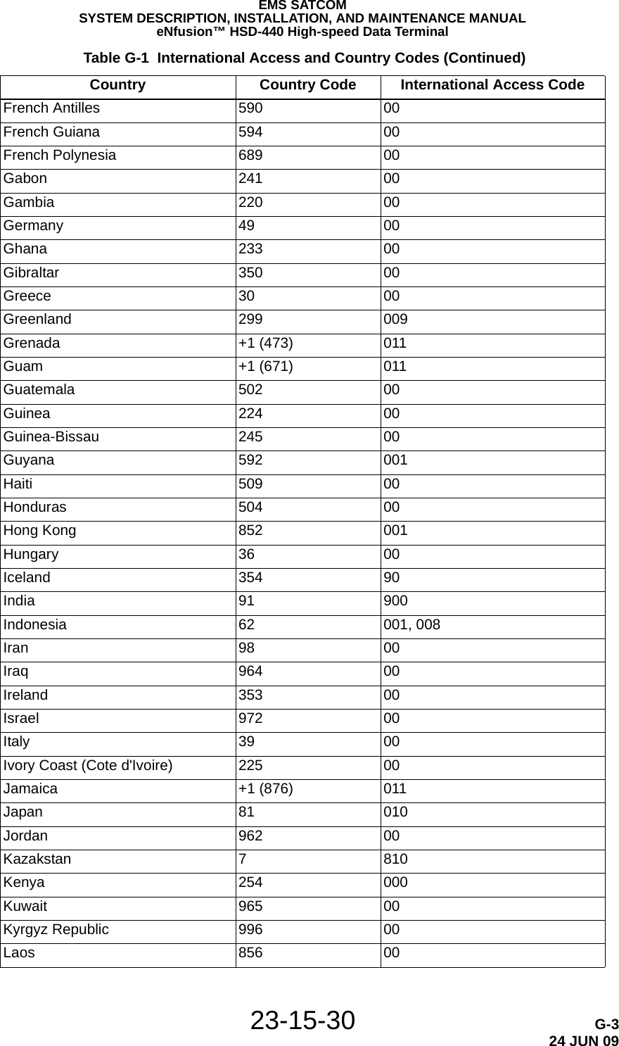
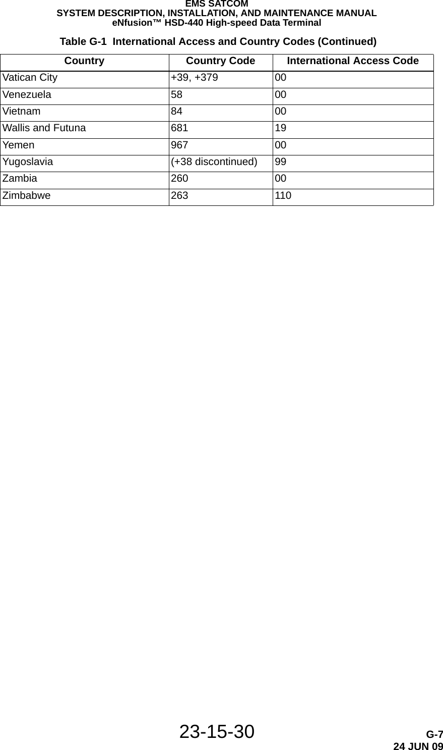
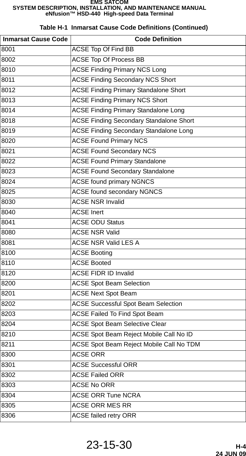
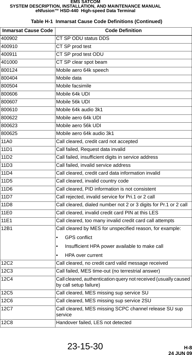
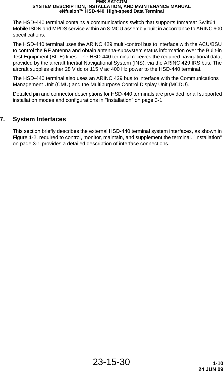
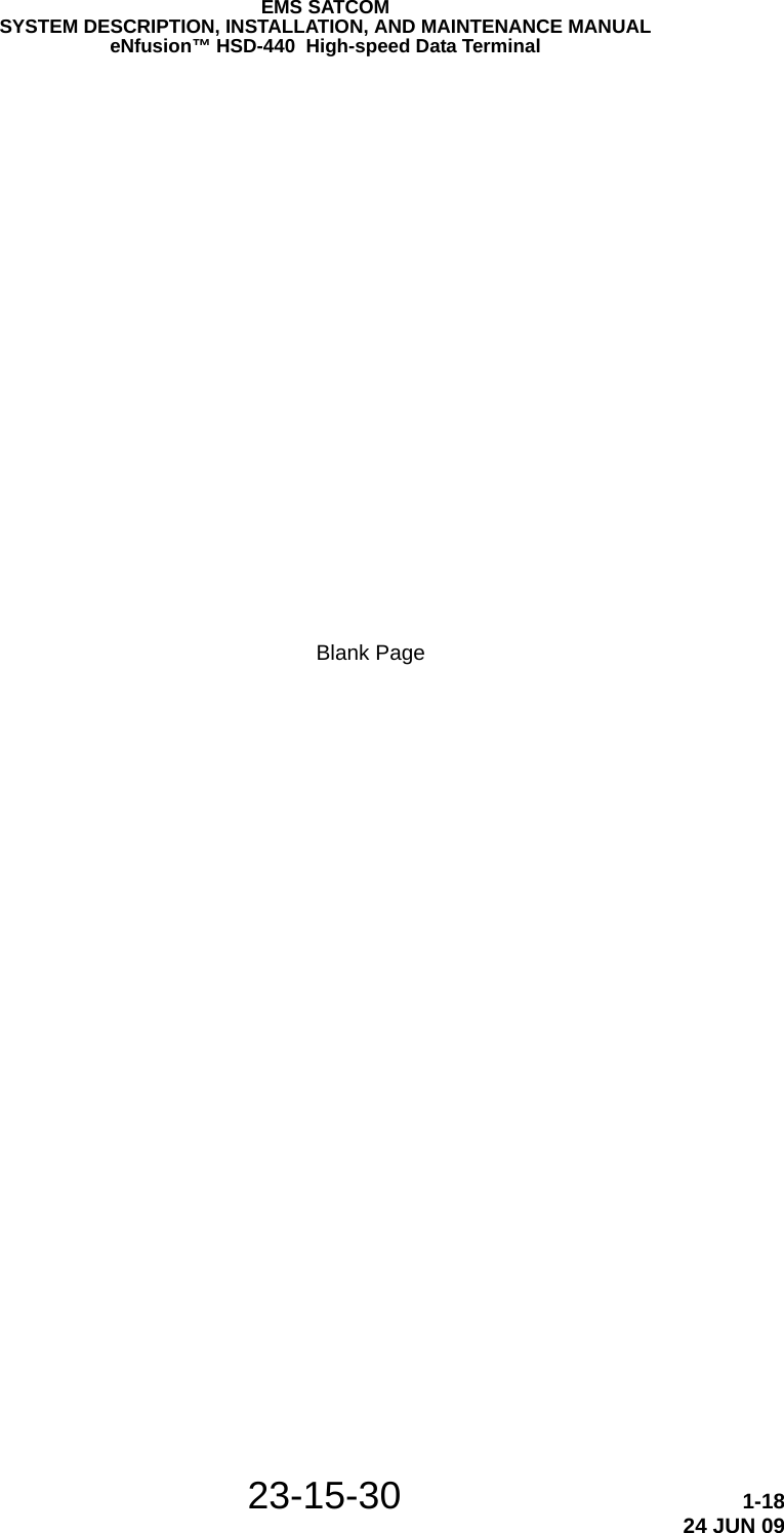
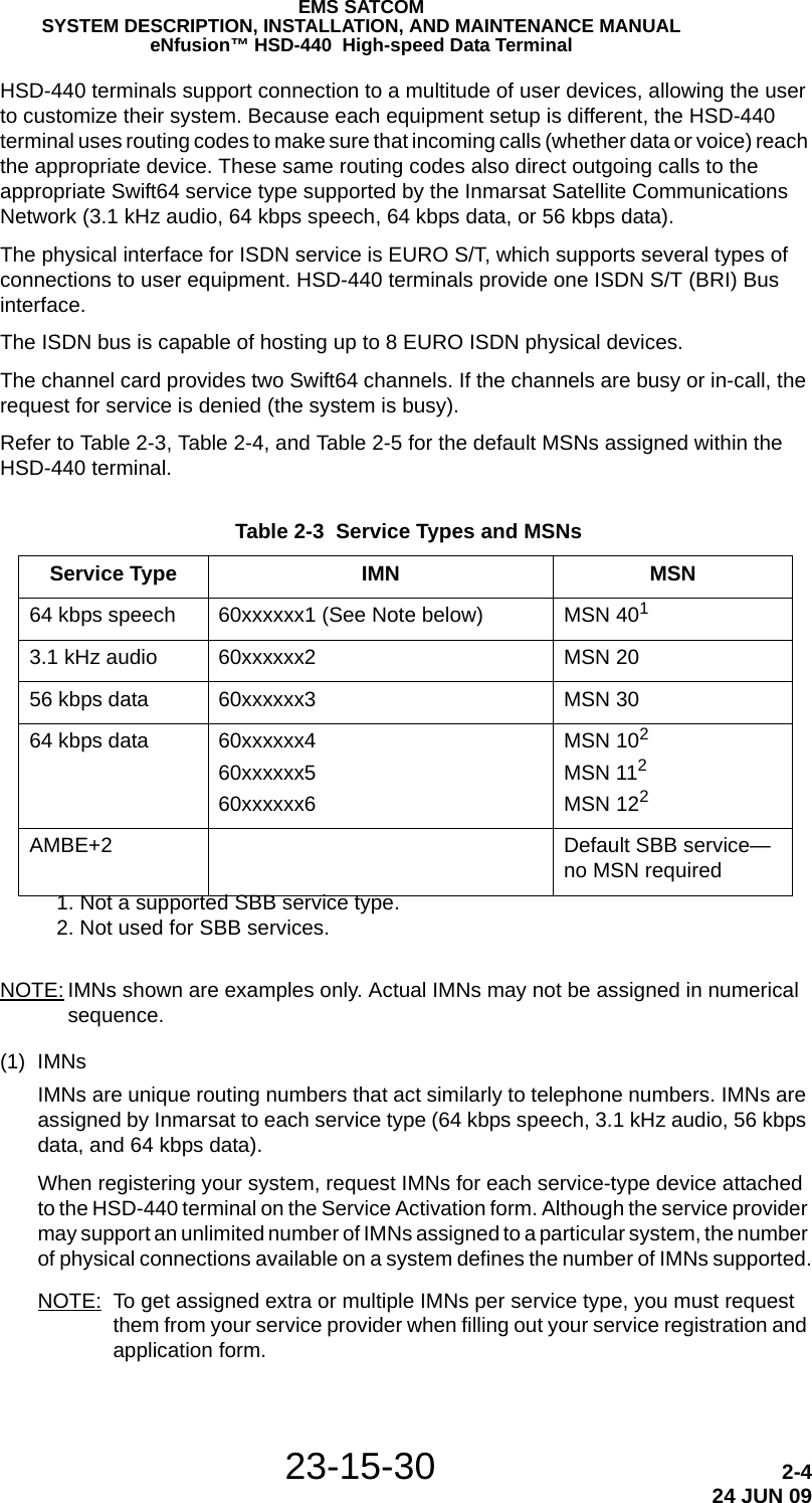
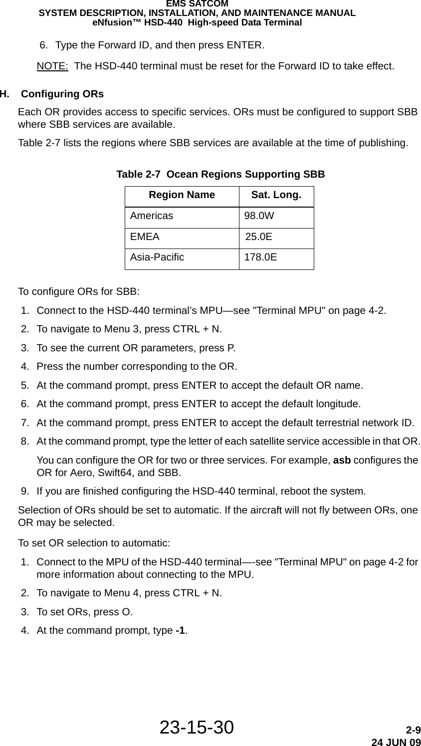
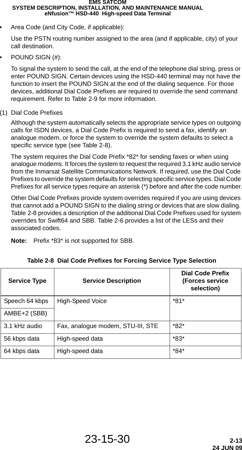
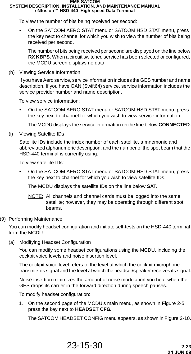
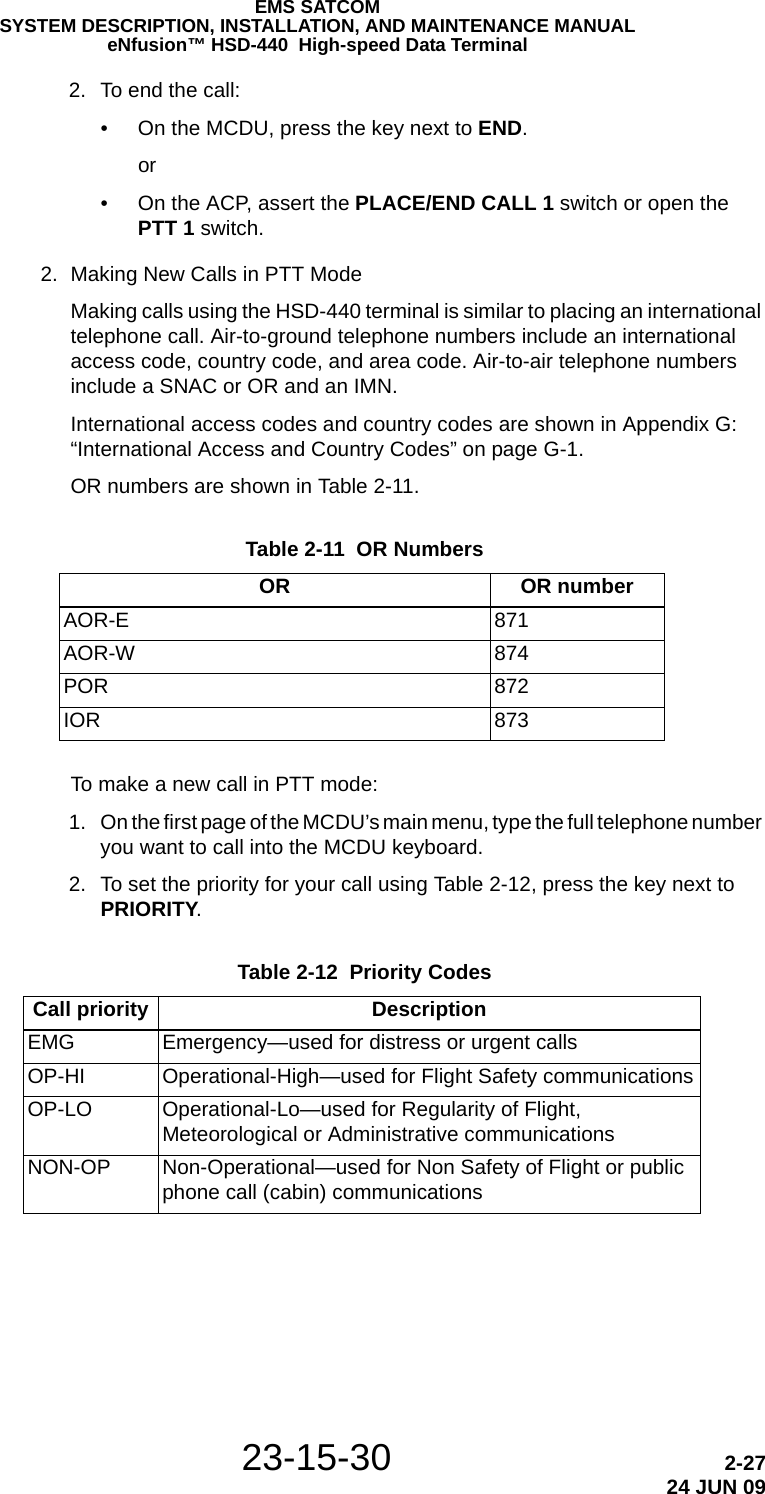
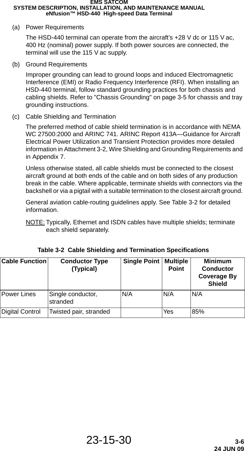
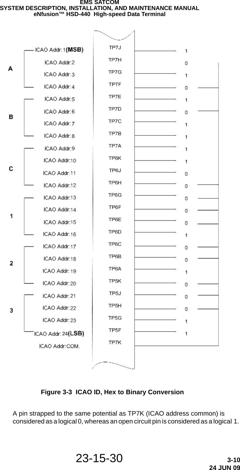
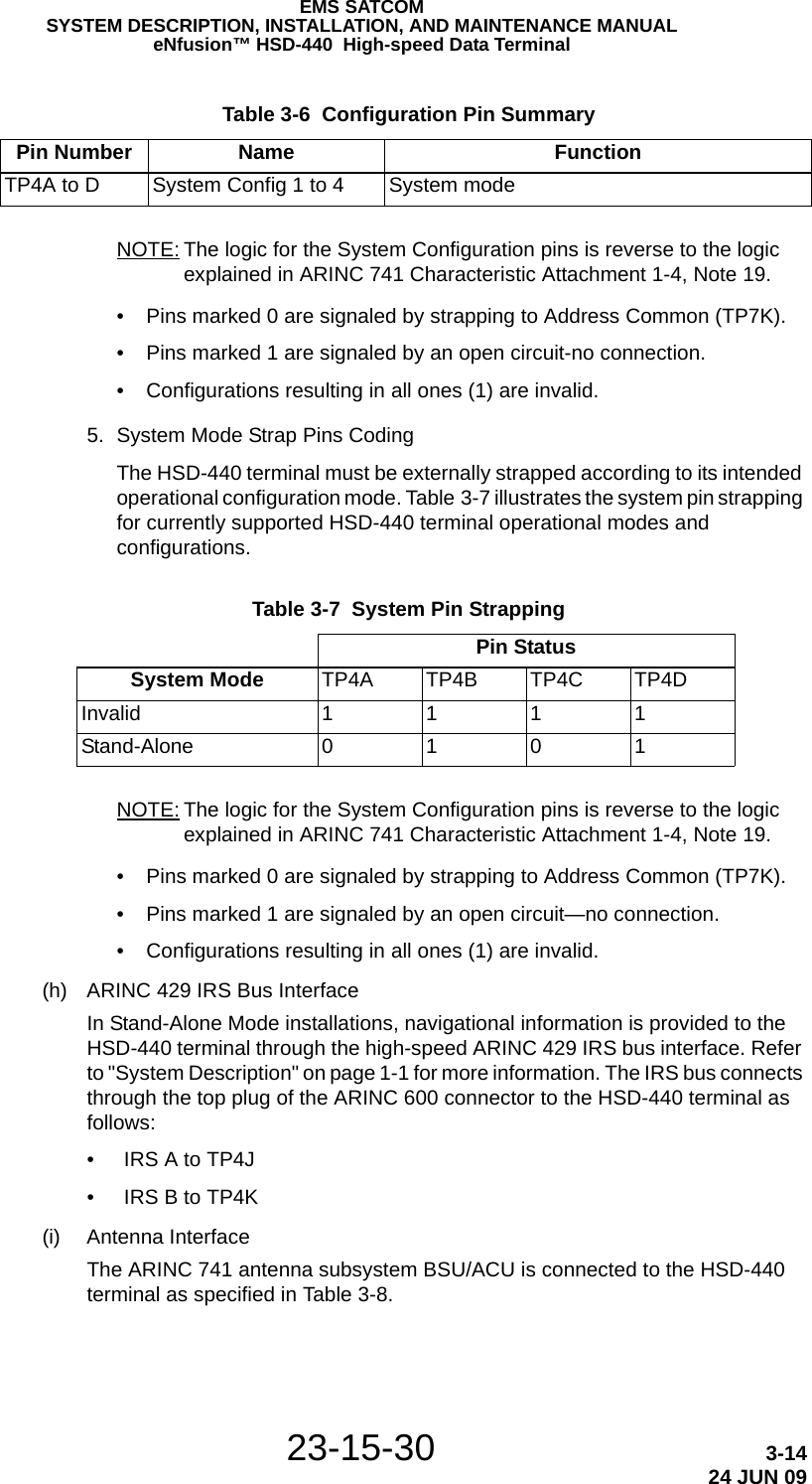
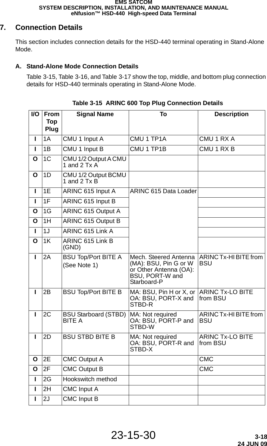
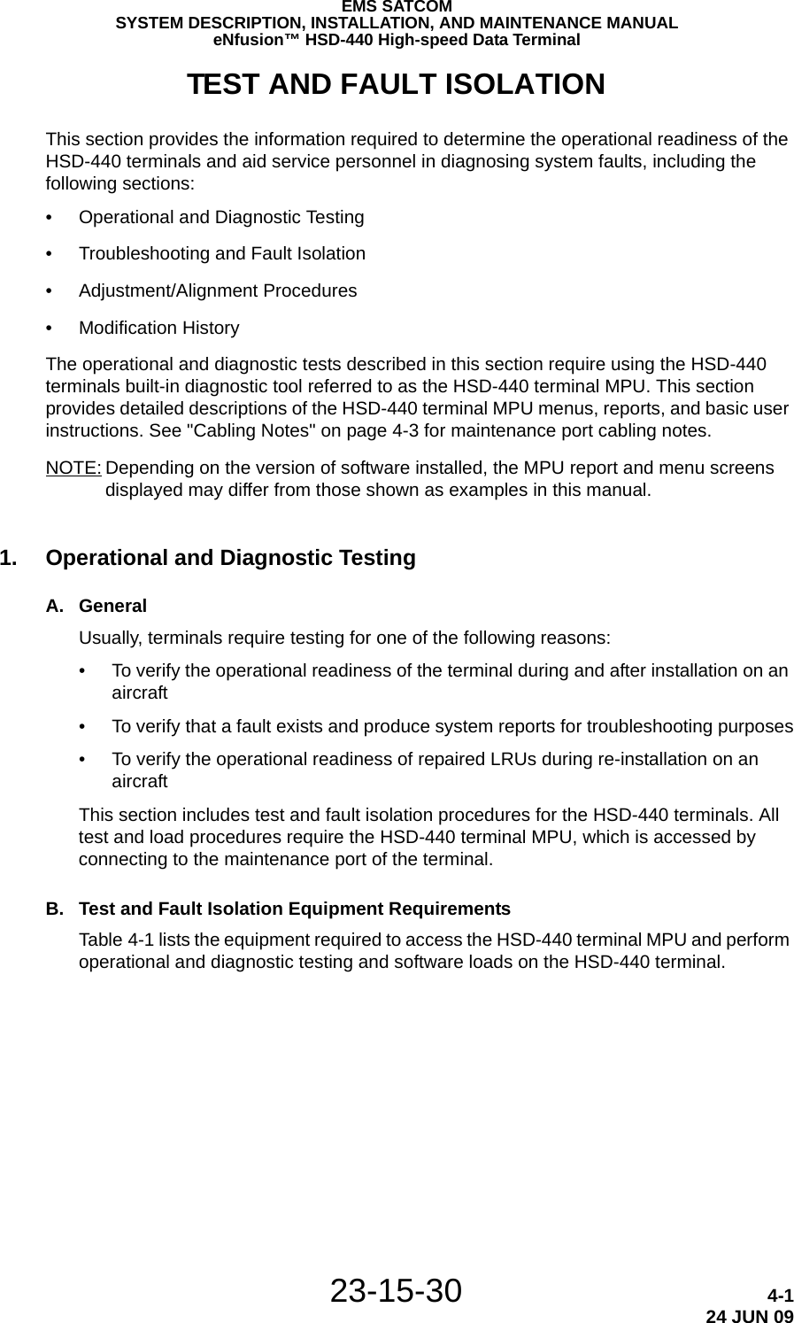
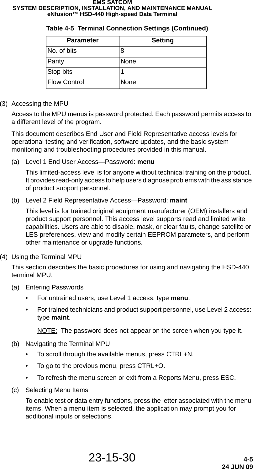
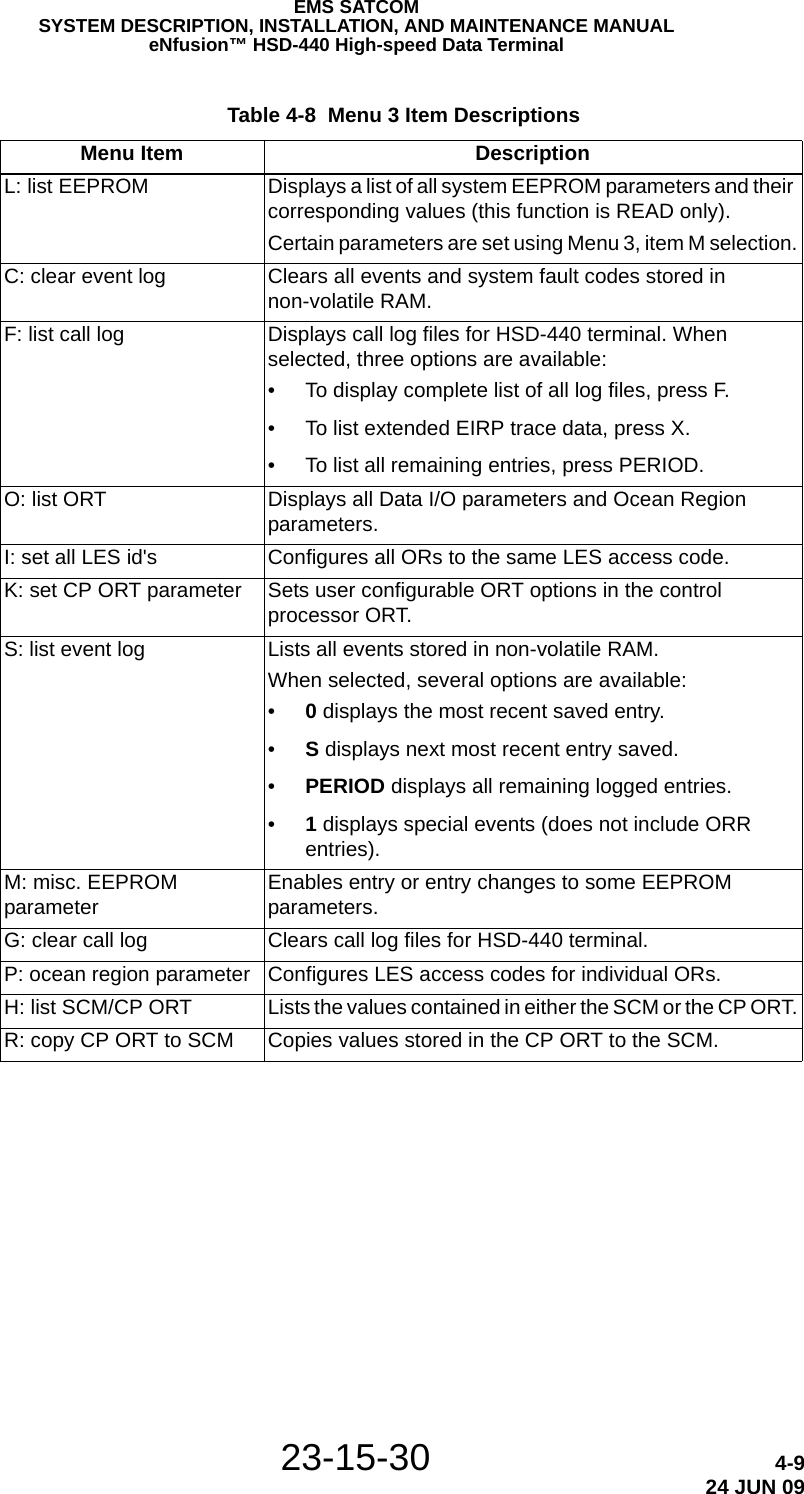
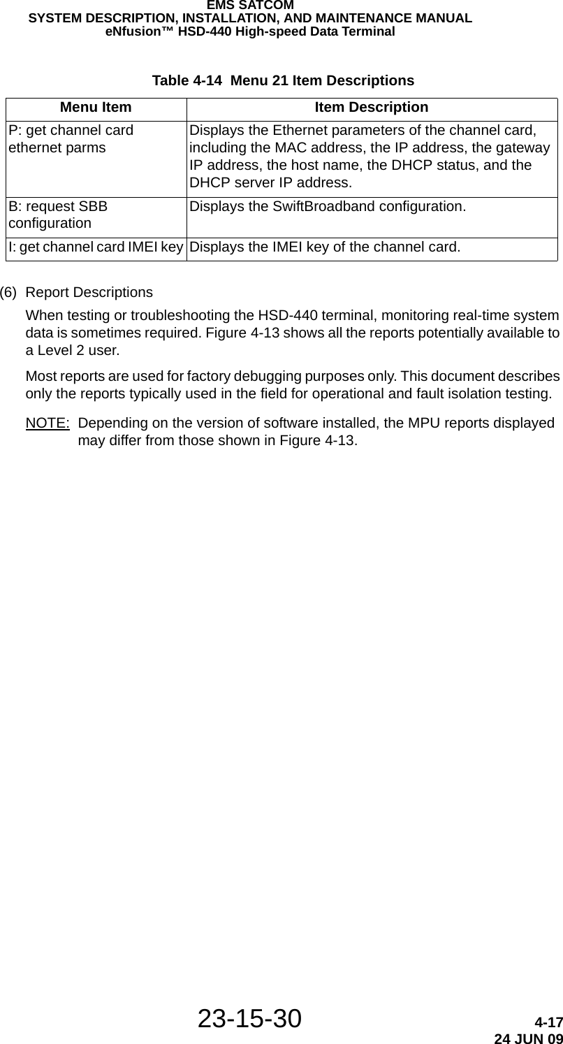
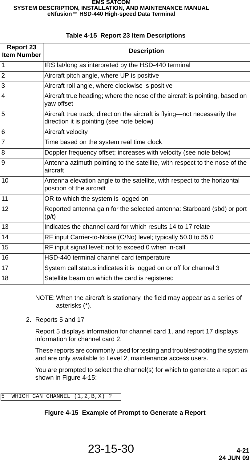
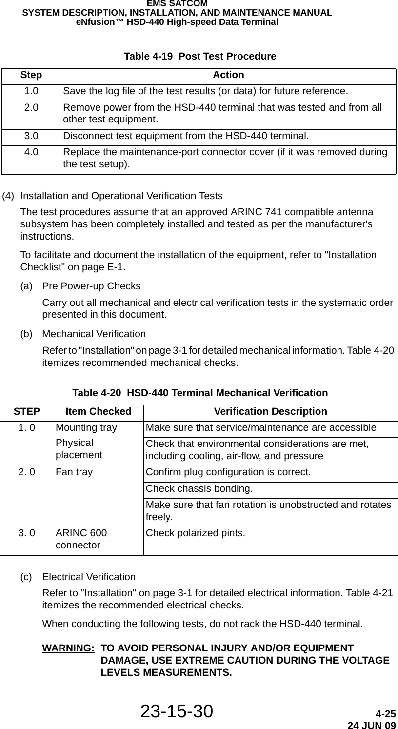
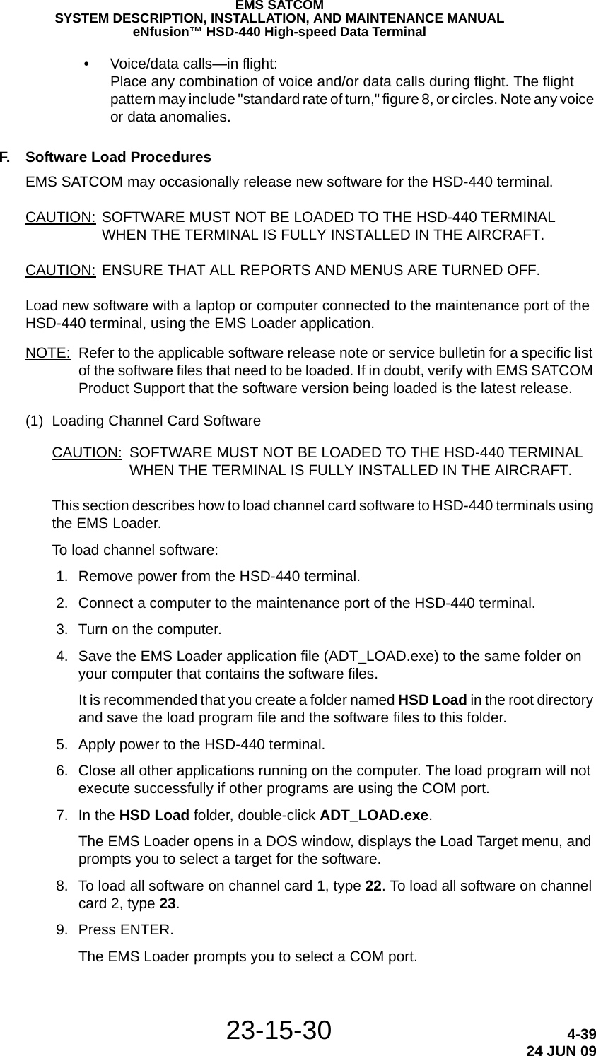
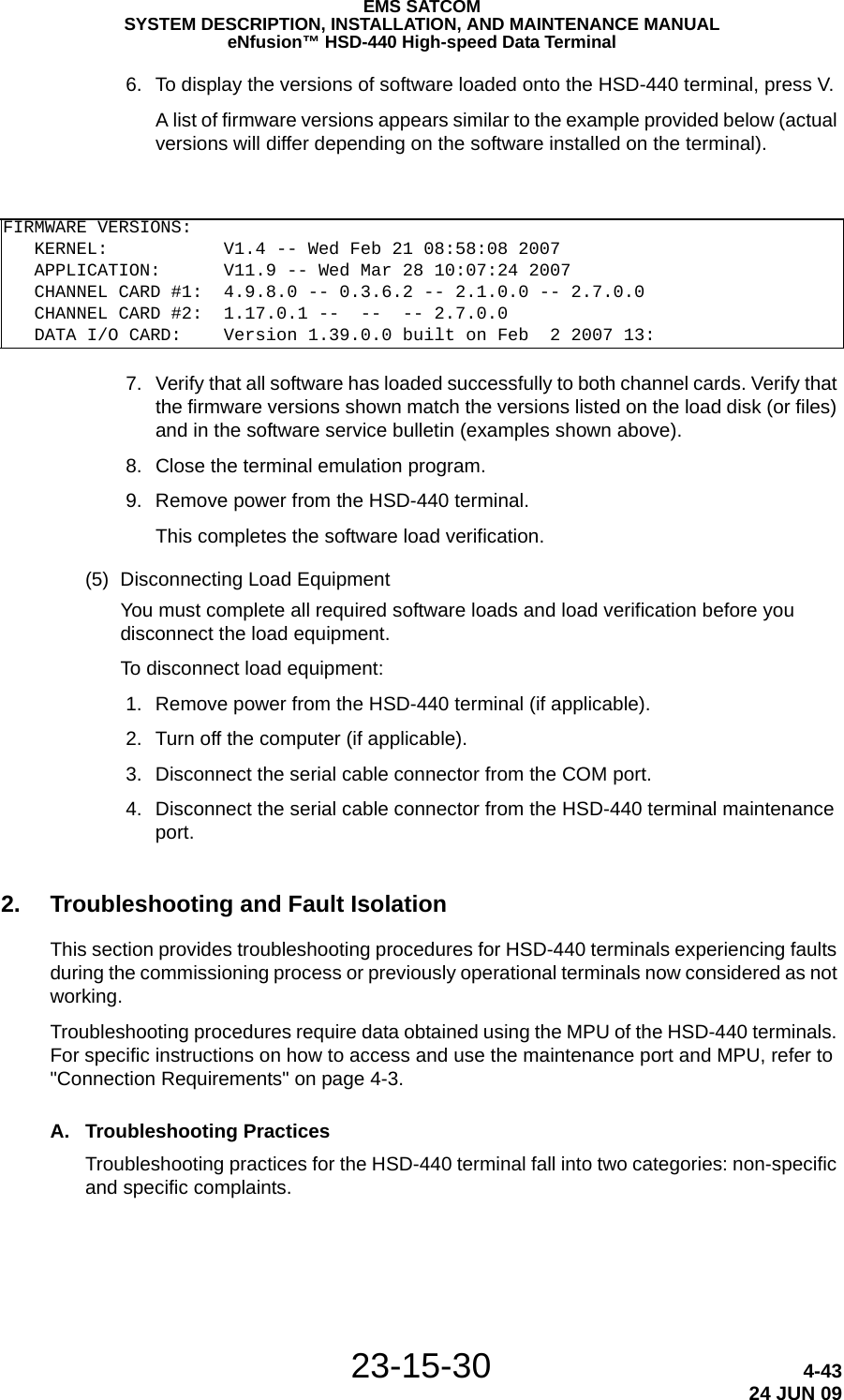
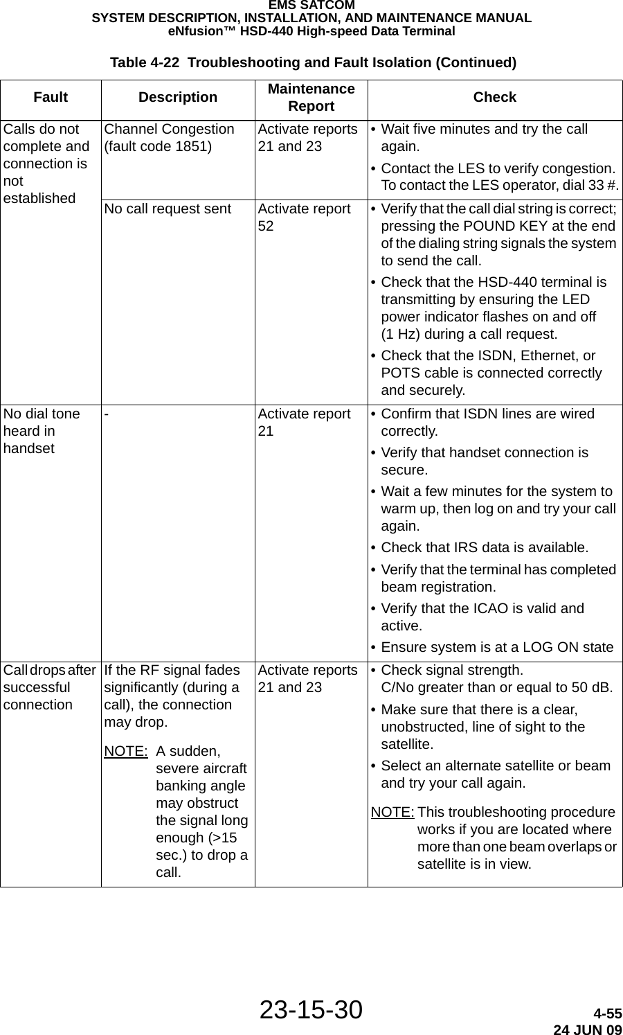
![23-15-30 1-824 JUN 09EMS SATCOMSYSTEM DESCRIPTION, INSTALLATION, AND MAINTENANCE MANUALeNfusion™ HSD-440 High-speed Data Terminal4. Software DescriptionThis section describes the software specifications and operational software components of HSD-440 terminals.A. Software SpecificationsThe software meets the following DO-178B standards:• Swift64 to Level D• Classic Aero voice and data to Level D• SwiftBroadband to Level EB. Operational Software Part NumbersTable 1-3 provides a list of software part numbers for the HSD-440 terminal.16.5.2.1 Abnormal Operating Conditions A(WF)H16.5.2.2 Momentary Under Voltage Operation A(WF)H16.5.2.3 Abnormal Surge Voltage A(WF)H17.4 Voltage Spike A18.0 Audio Frequency Conducted Susceptibility [K(WF)Z]19.3 Induced Signal Susceptibility ZW20.0 Radio Frequency SusceptibilityConducted Susceptibility RRadiated Susceptibility R21.0 Emission of RF EnergyConducted (Power Lines) BConducted RF Emission BRadiated RF Emission B22.0 Lightning Induced Transient Susceptibility A3J33 (modified)23.0 Lightning Direct Effects X24.0 Icing X25.0 Electrostatic Discharge (ESD) A (modified)26.0 Fire Flammability C Table 1-2 HSD-440 Terminal RTCA/DO-160E Environmental Characteristics (Continued) Section Environmental Condition Category](https://usermanual.wiki/EMS-Technologies-Canada/HSD-440/User-Guide-1257851-Page-40.png)
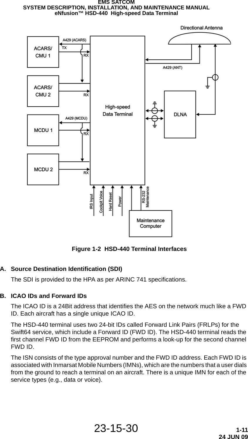
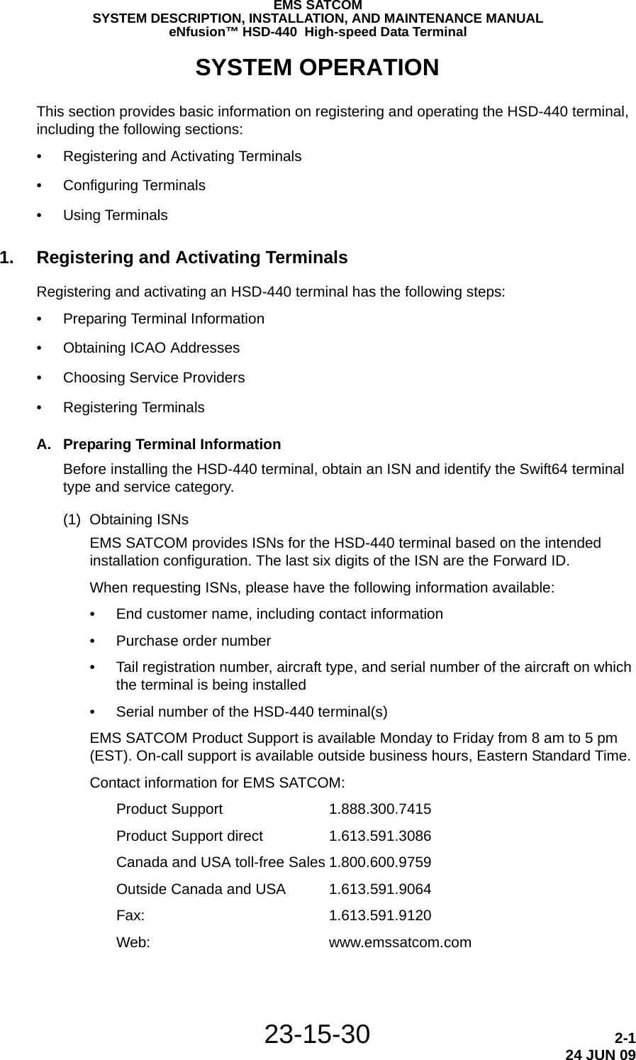
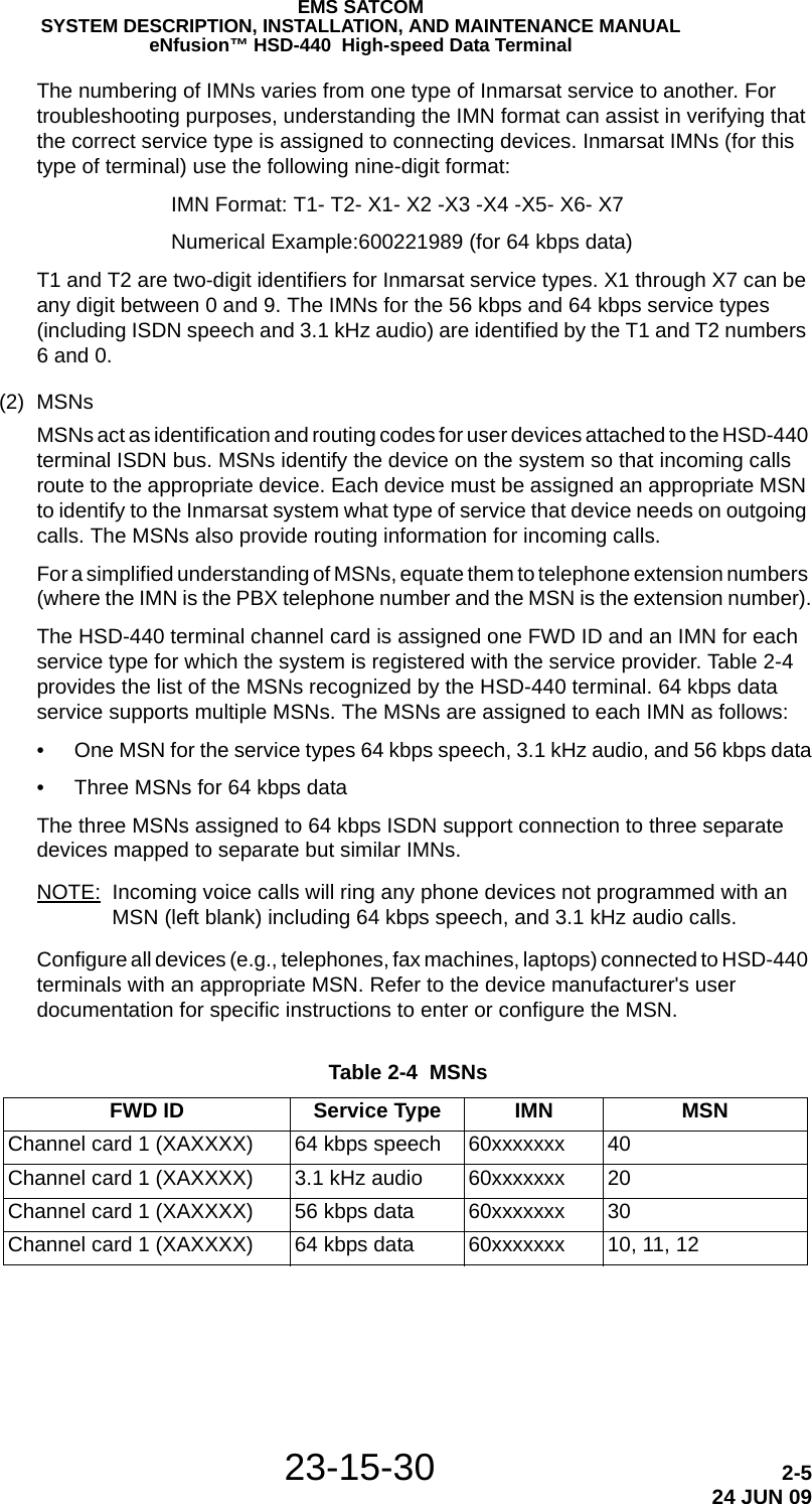
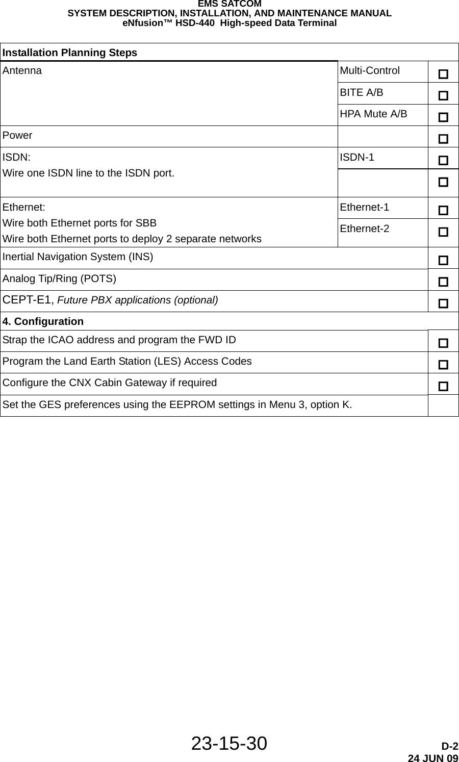
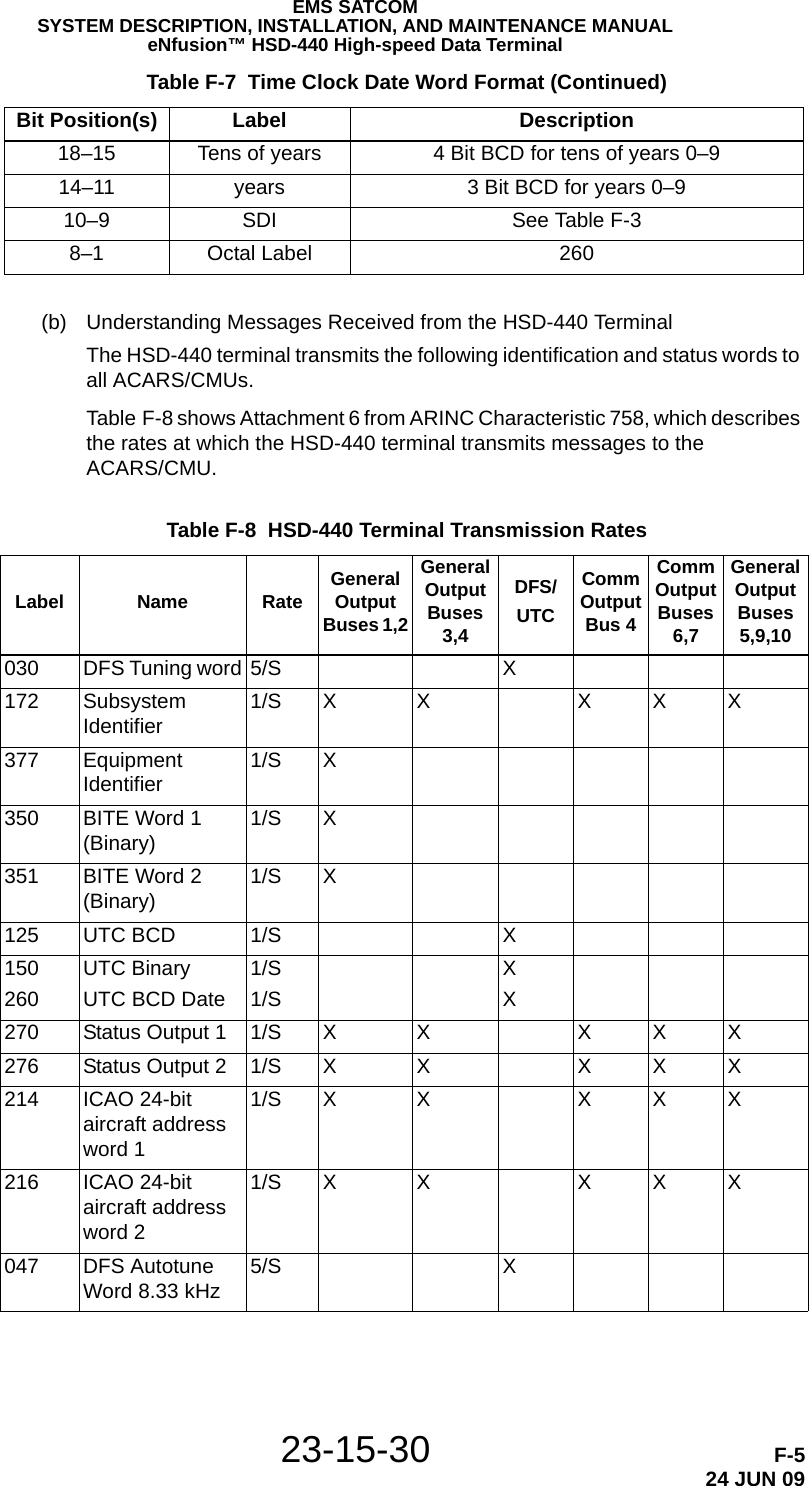
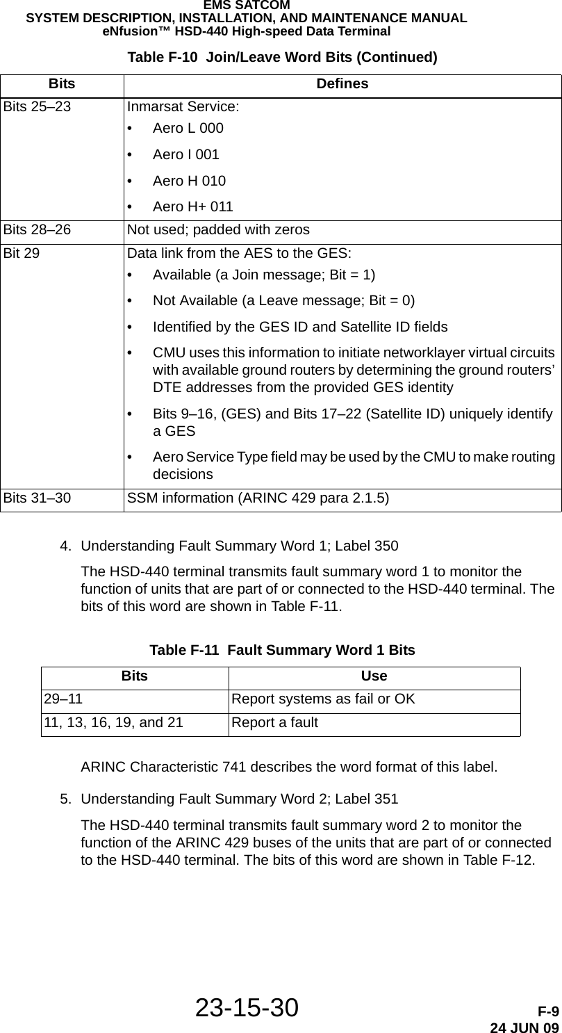
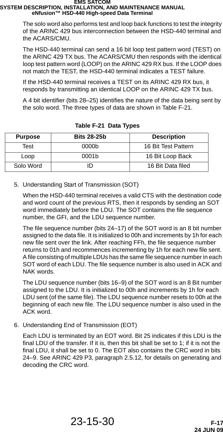
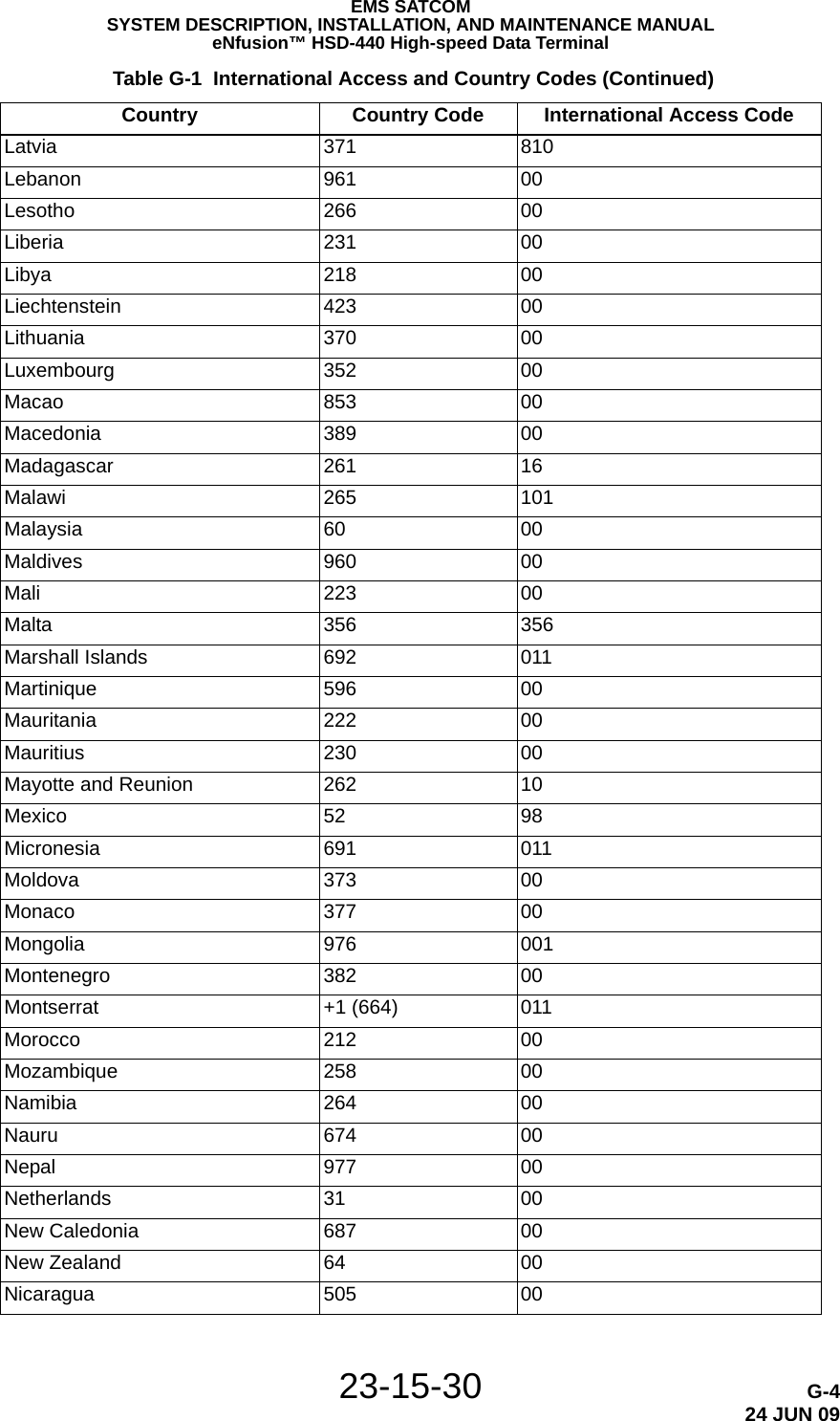
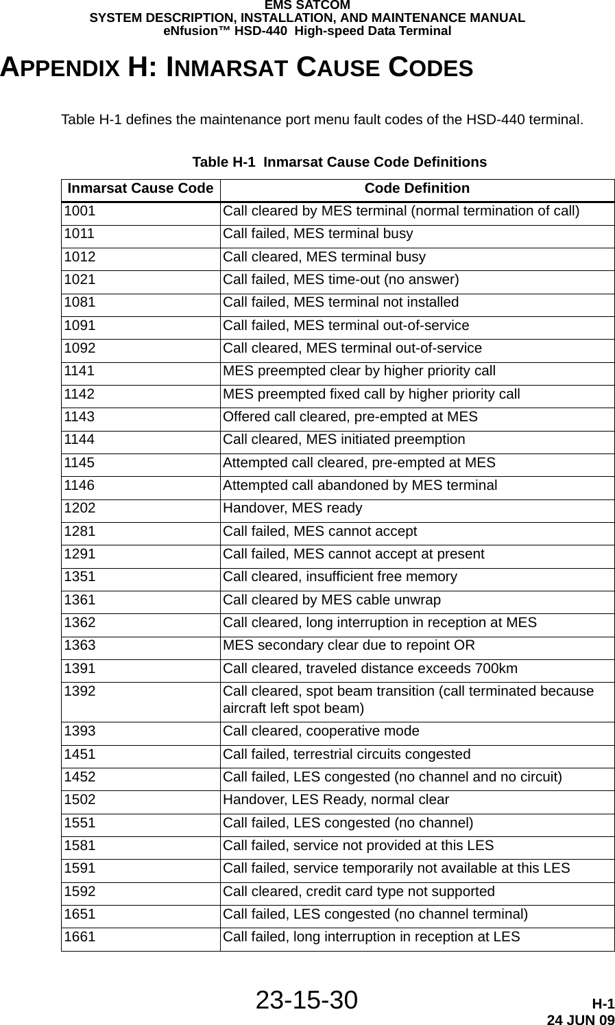
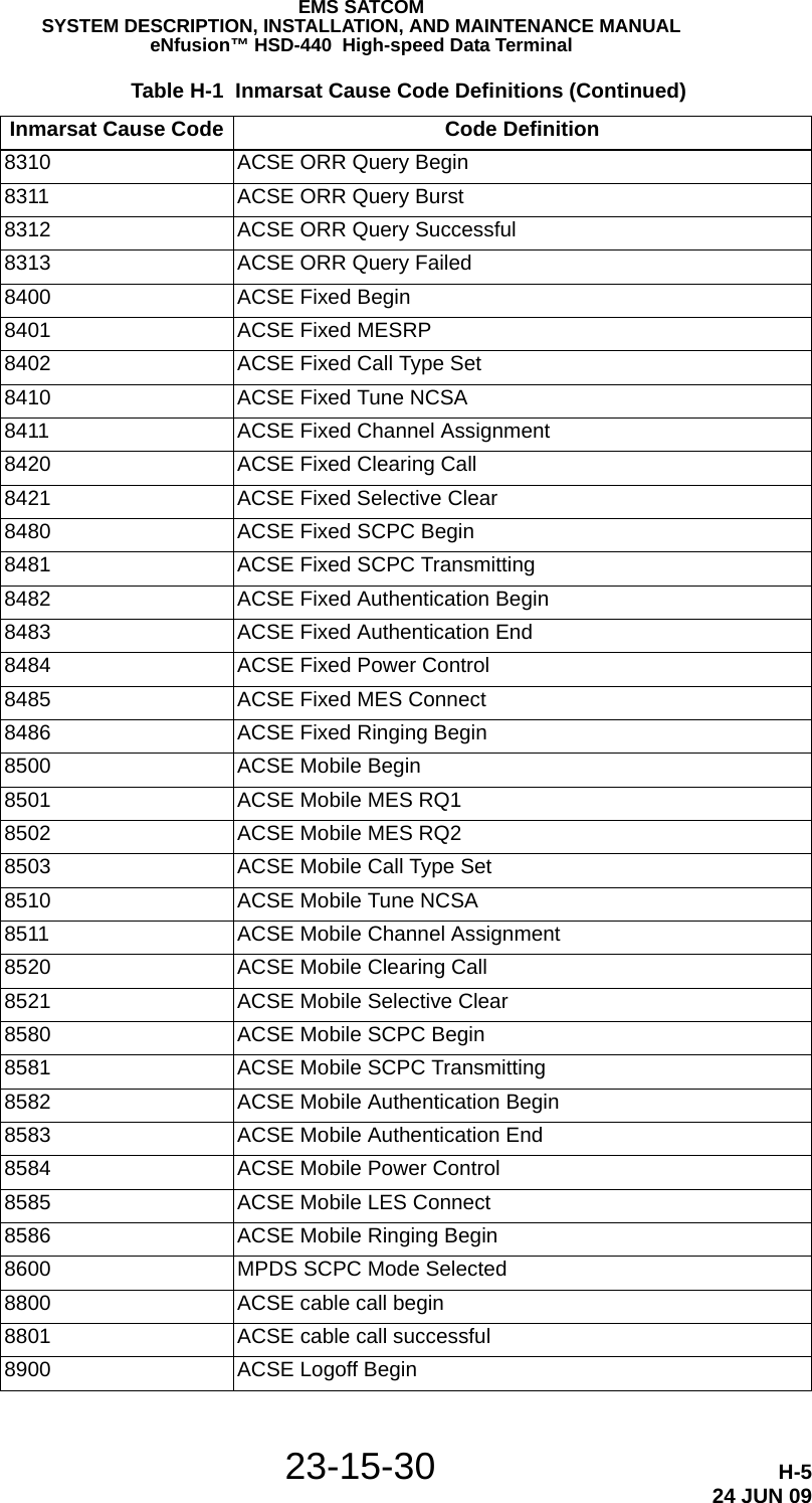
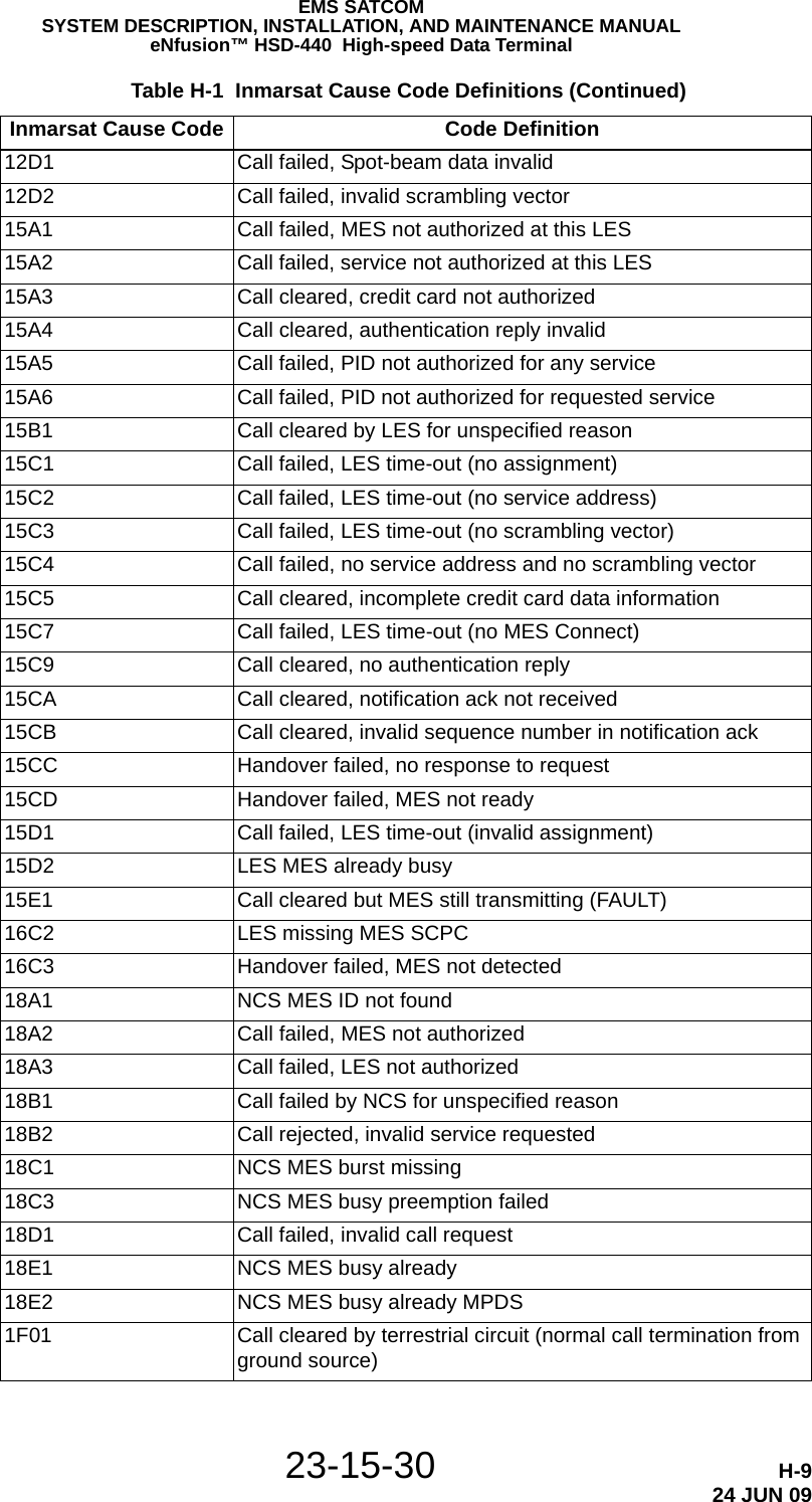
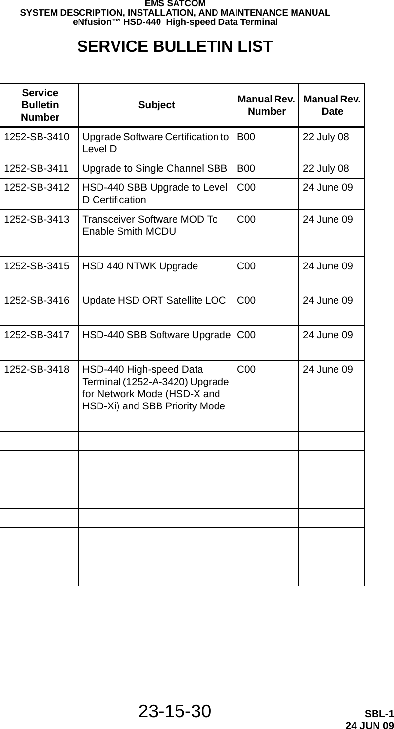
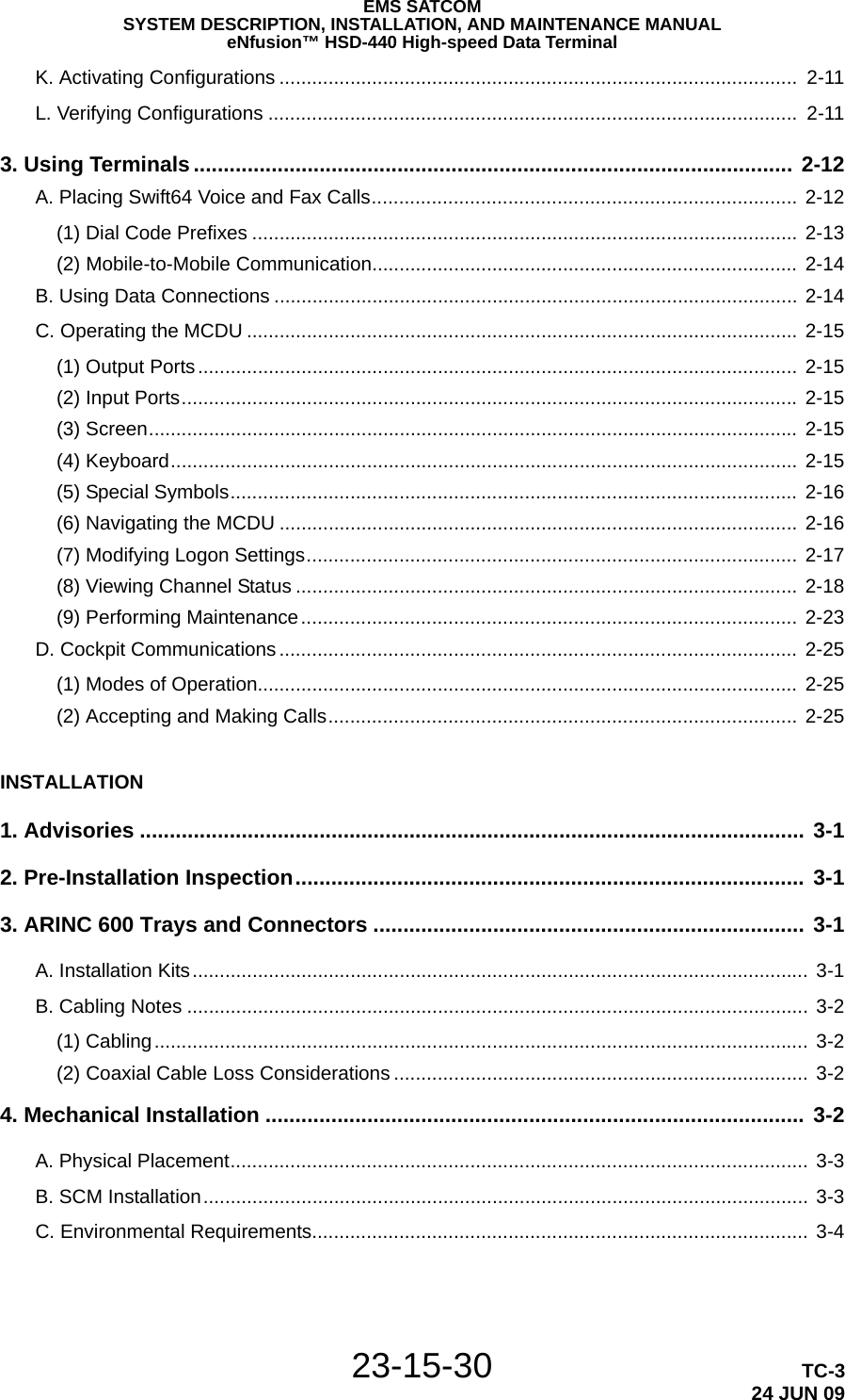
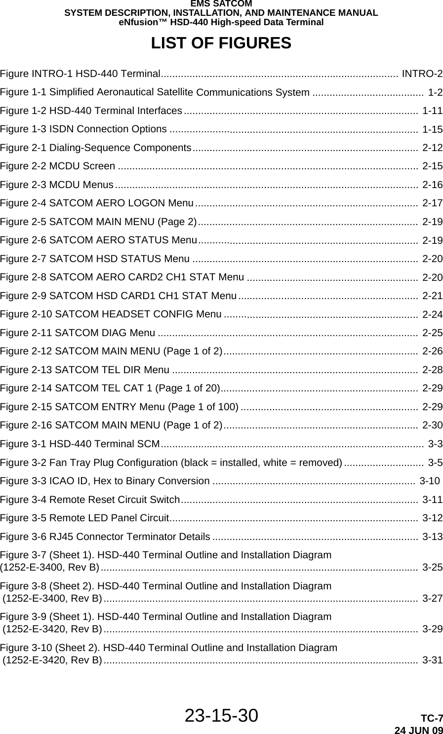
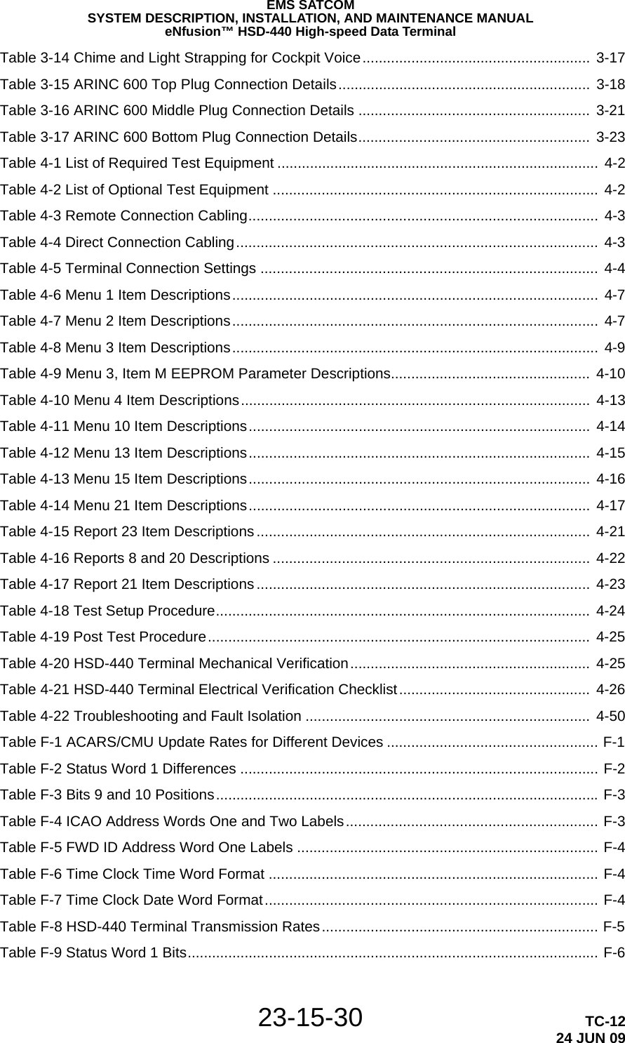
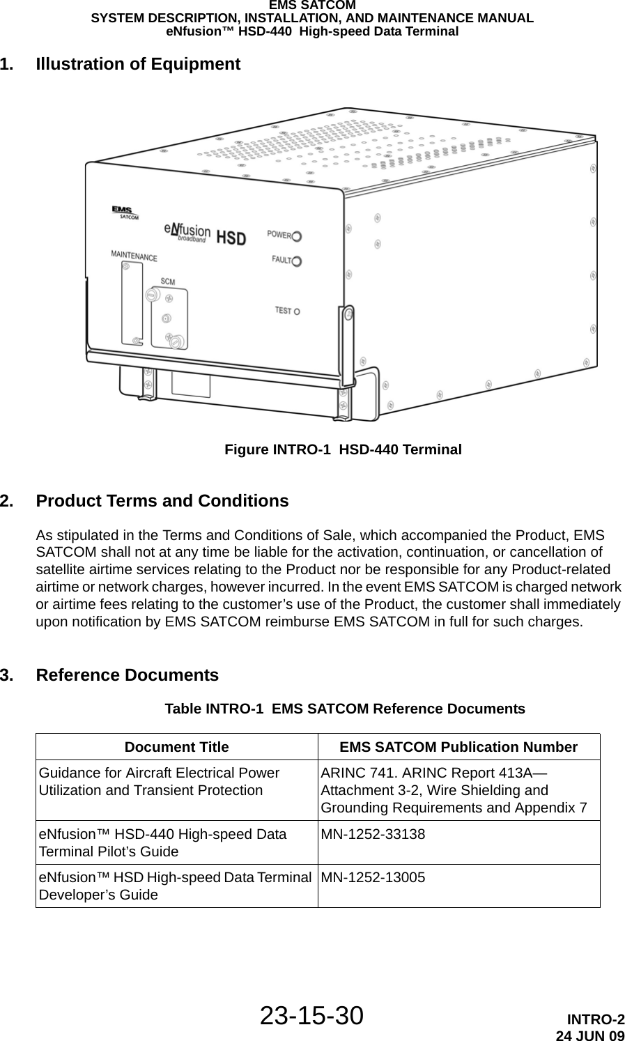
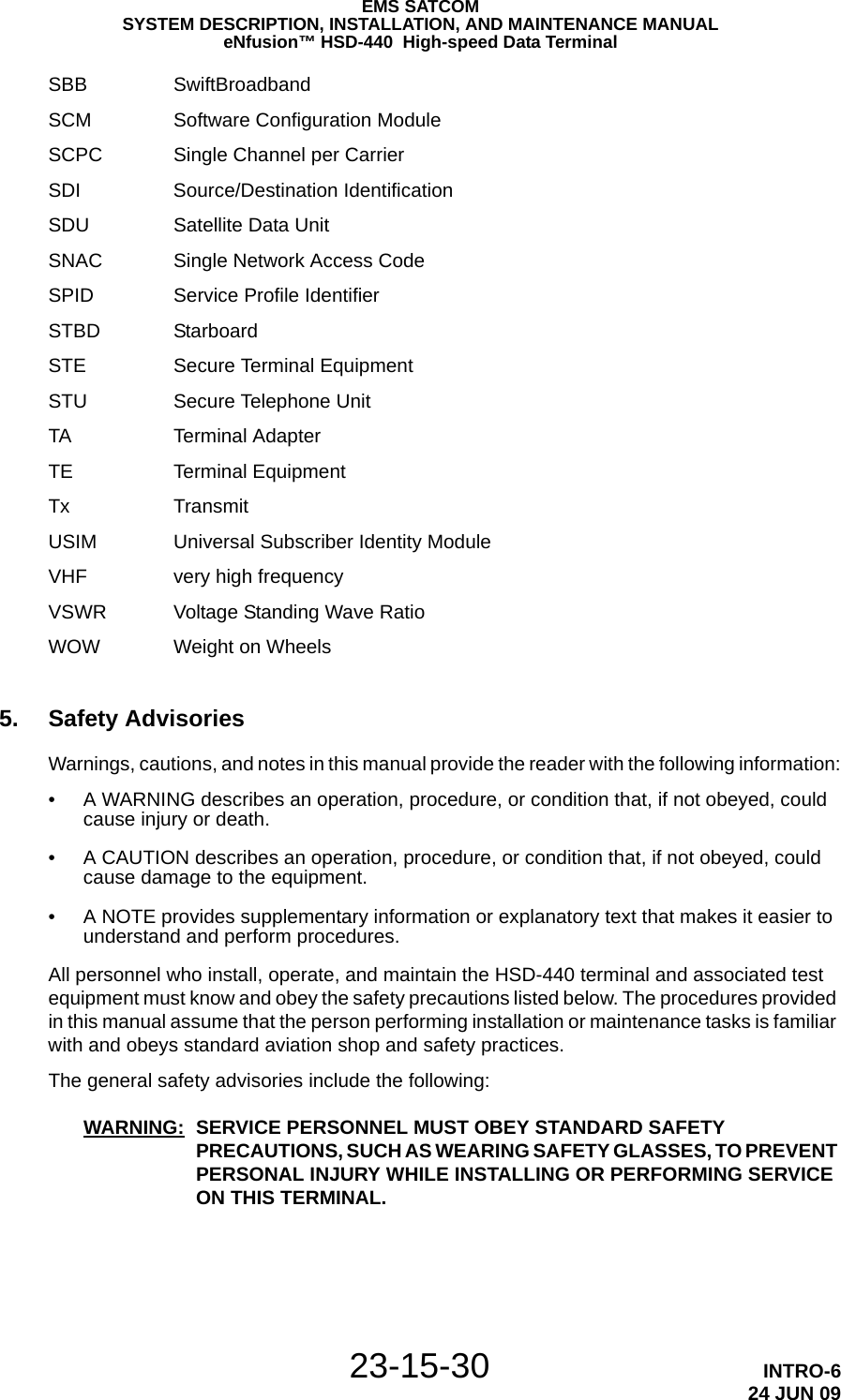
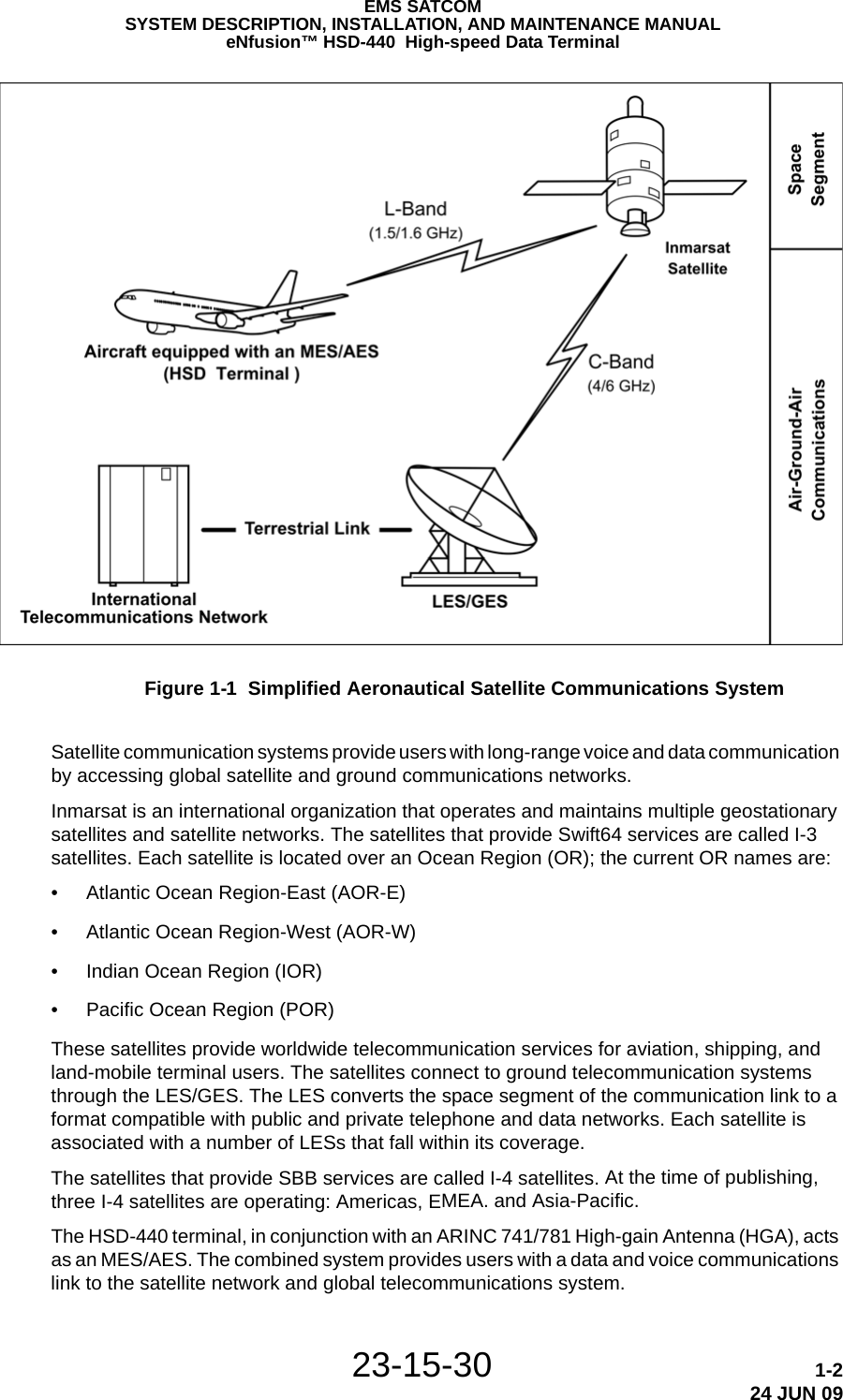
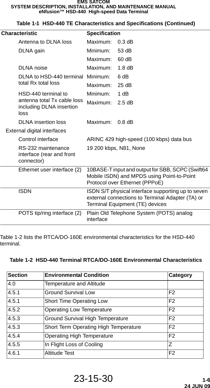
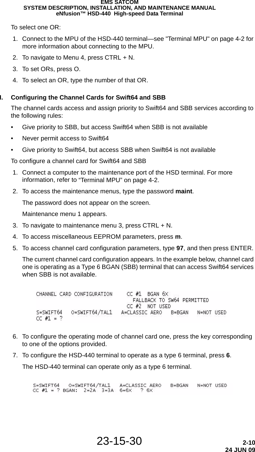
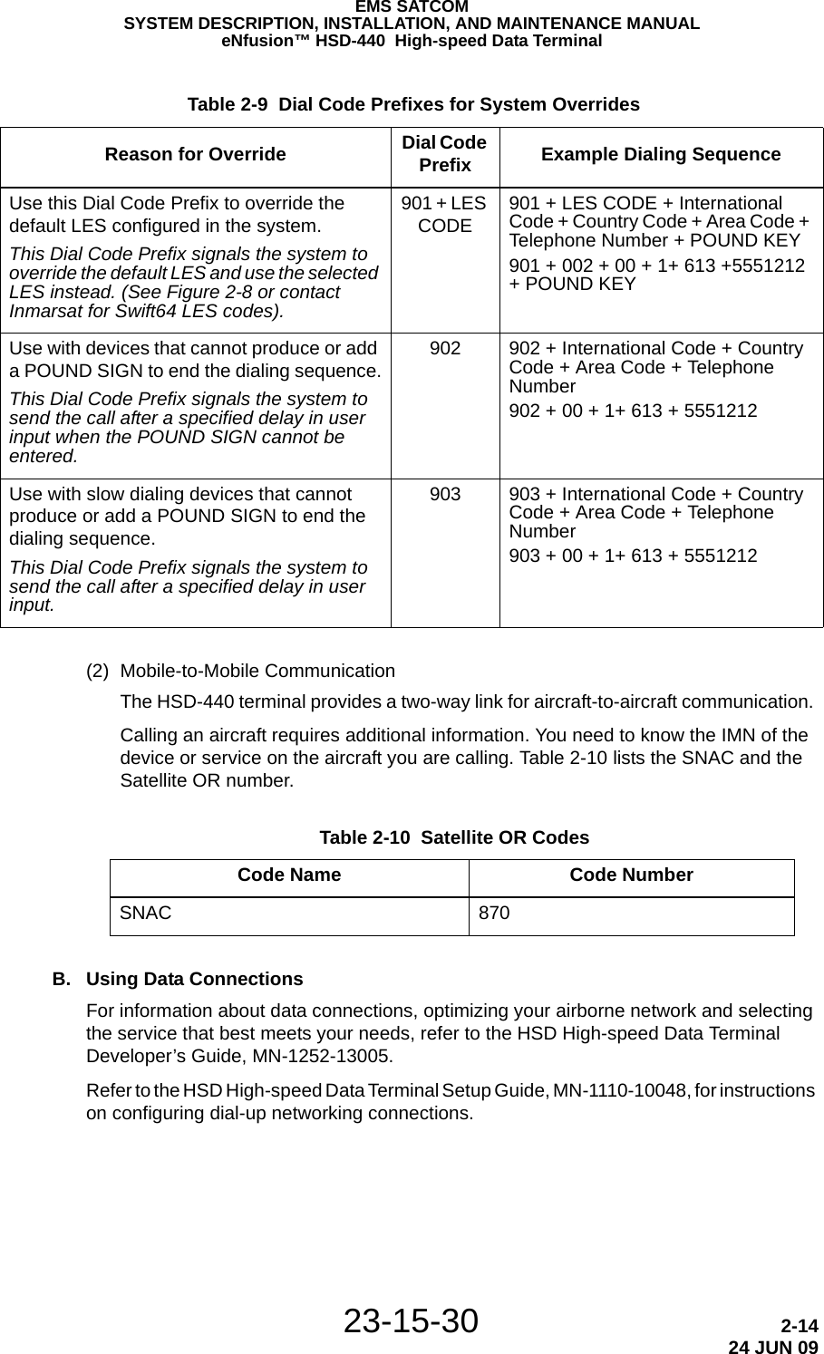
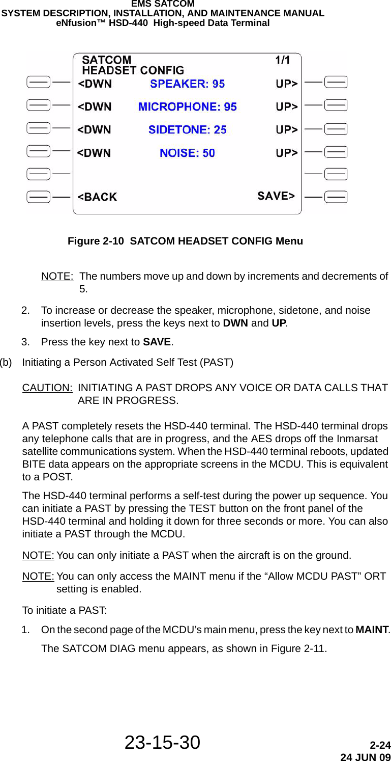
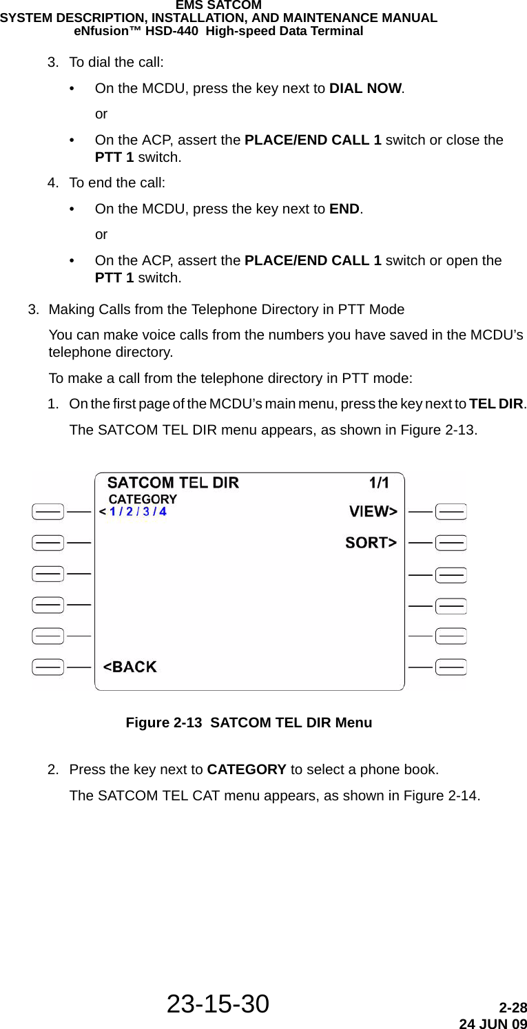
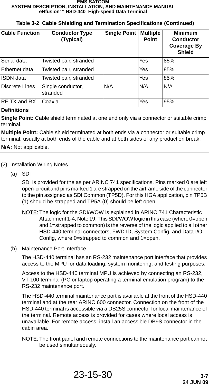
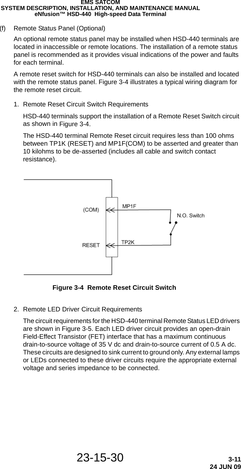
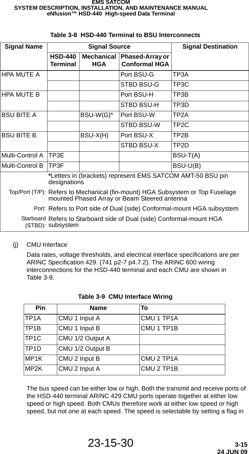
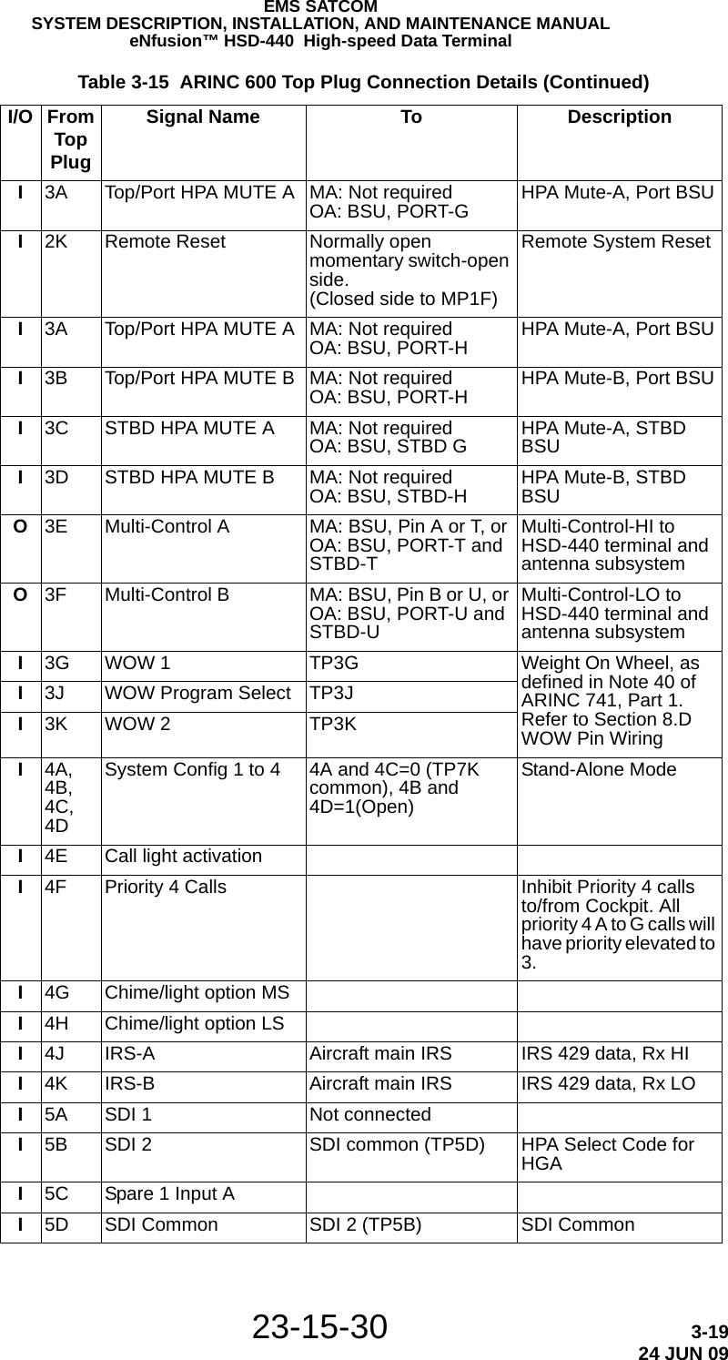
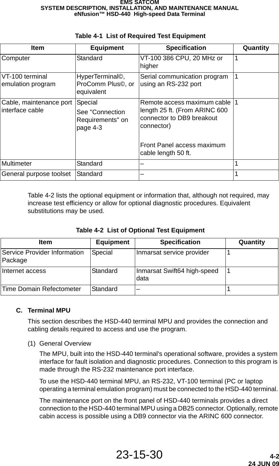
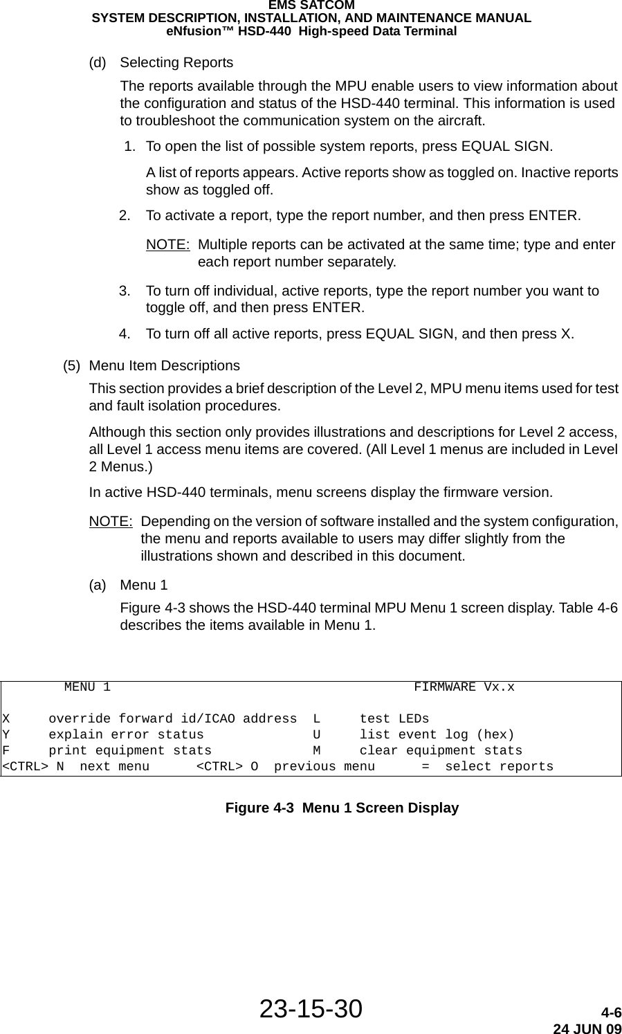
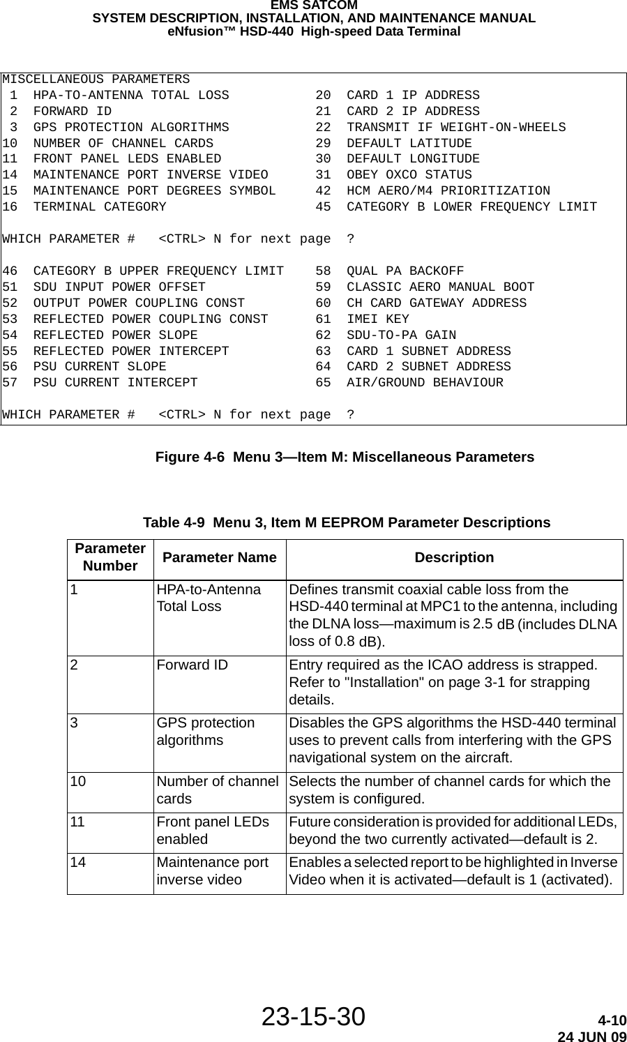
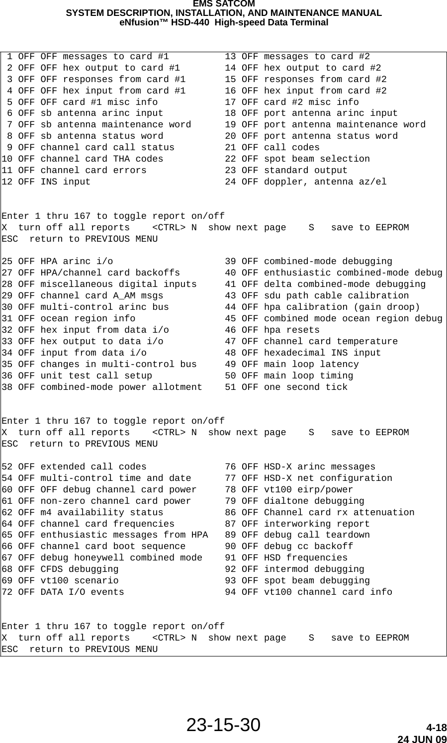
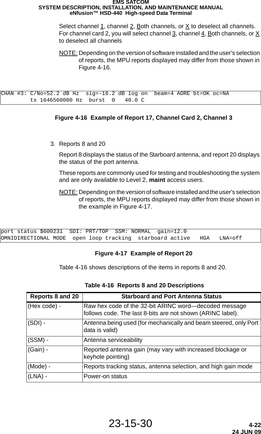
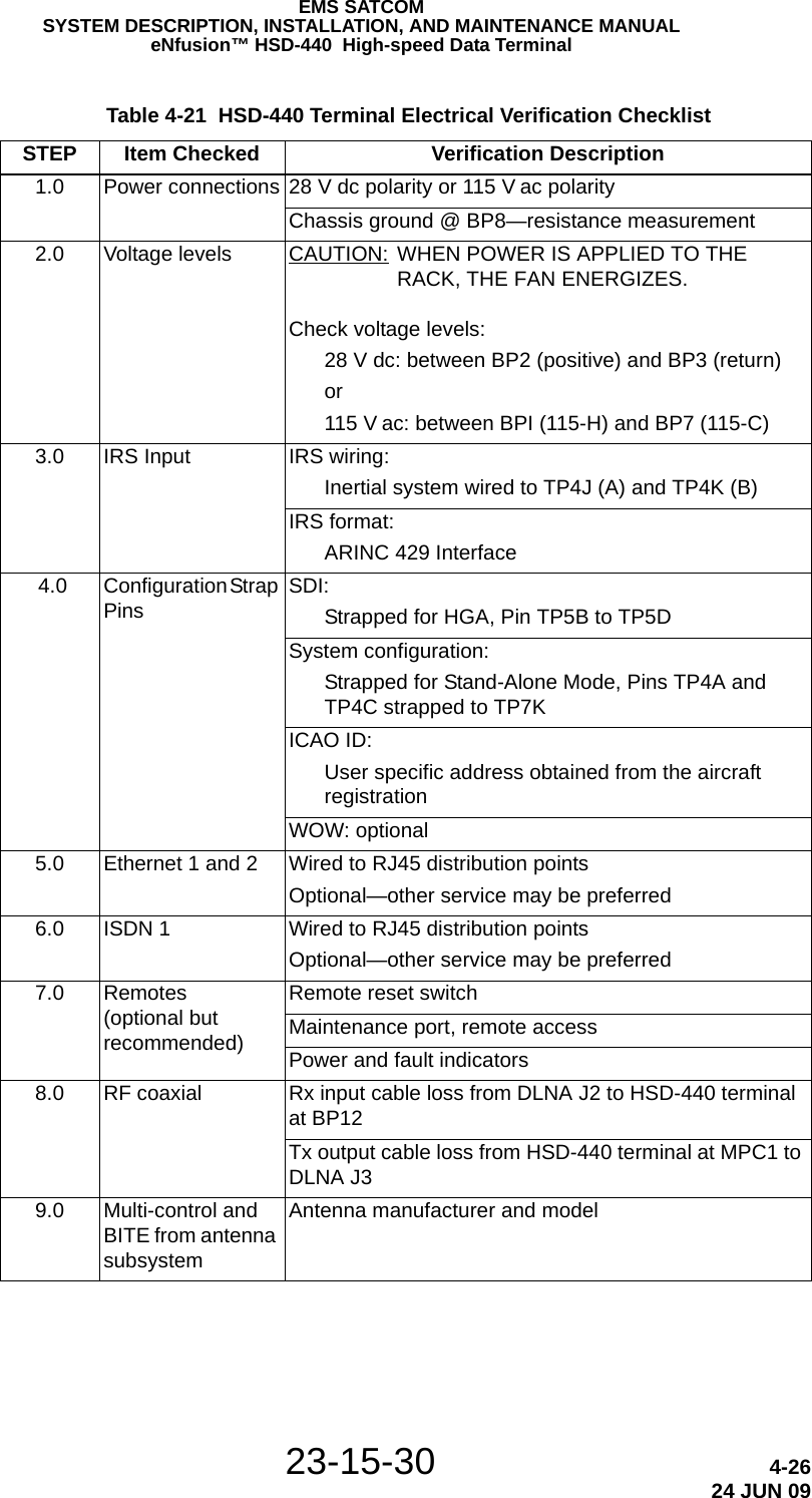
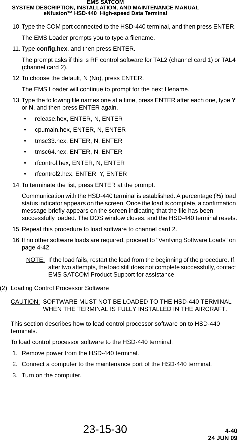
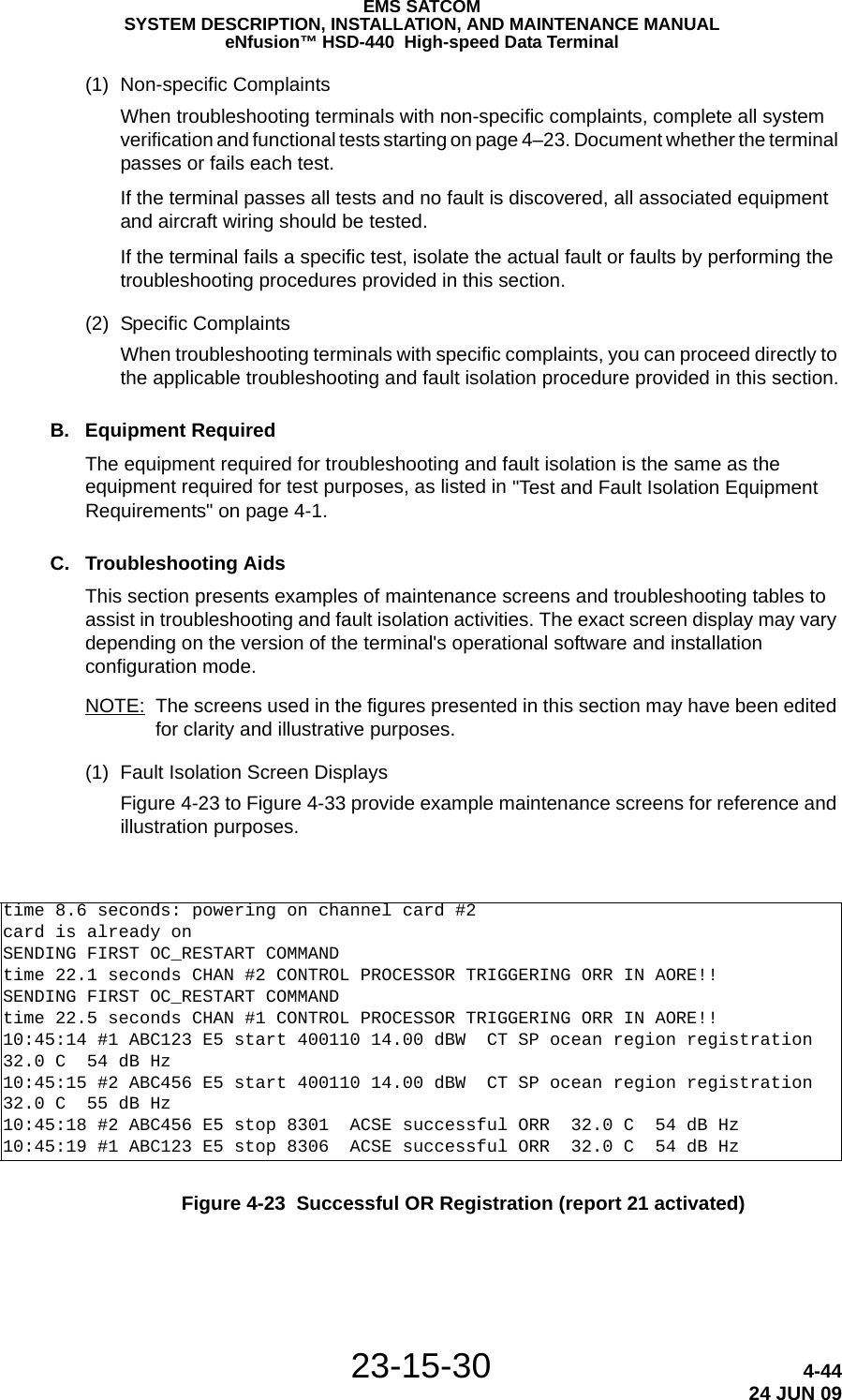
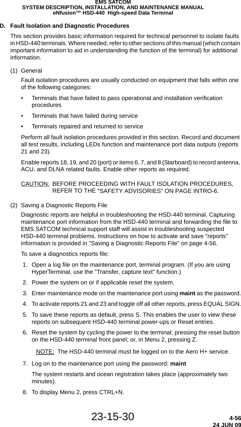
![23-15-30 2-824 JUN 09EMS SATCOMSYSTEM DESCRIPTION, INSTALLATION, AND MAINTENANCE MANUALeNfusion™ HSD-440 High-speed Data Terminal(1) Changing LES Access Codes using the Control Processor SoftwareTo change all of the LES Access Codes simultaneously to the same LES Access Code: 1. Connect to the Maintenance Port Utility (MPU) of the HSD-440 terminal—see "Terminal MPU" on page 4-2 for connection details. 2. Type the password maint. 3. To navigate to maintenance menu 3, press CTRL + N. 4. In Menu 3, press K. 5. Follow the application prompts, and enter the LES Access Code.(2) Changing LES Access Codes on a Call-by-Call BasisTo change the LES Access Code on a call-by-call basis in all control processor software versions:• Enter the following dial-sequence (Xantic POR LES Access Code [012] as an example only):NOTE: You can also change the LES code on a call-by-call basis using the Dial Code Prefix 901 when troubleshooting and diagnosing network problems. G. Configuring Forward IDsTo configure Forward IDs: 1. Connect to the Maintenance Port Utility (MPU) of the HSD-440 terminal—see "Terminal MPU" on page 4-2 for connection details. 2. Type the password maint. 3. To navigate to maintenance menu 3, press CTRL + N. 4. To set control processor ORT parameters, press K. 5. To configure the Forward ID, type 32, and then press ENTER. Table 2-6 Inmarsat Swift64 LES Operator and Access Codes Land Earth Station Operator Country OR AOR-E AOR-W IOR POR Vizada USA 001 001 001 001 Stratos UK/Canada 002 002 002 002Stratos (Auckland LES)Xantic (Burum LES)Xantic (Perth LES)New Zealand Netherlands Australia 012 012 012 012901 + LES CODE + International Code + Country Code + Area Code + Telephone Number + POUND/HASH KEYExample: 901 + 012 + 00 + 1+ 613+5551212 + #](https://usermanual.wiki/EMS-Technologies-Canada/HSD-440/User-Guide-1257851-Page-58.png)
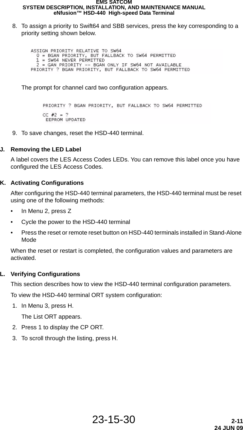
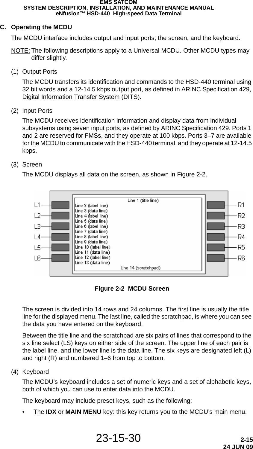
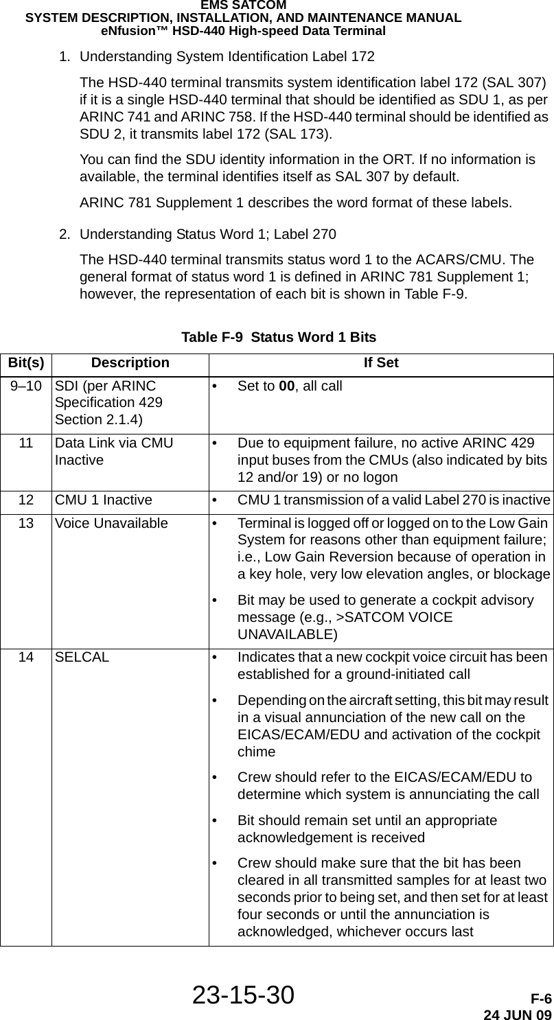
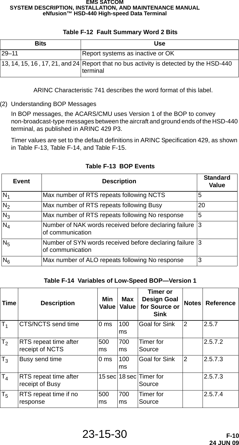
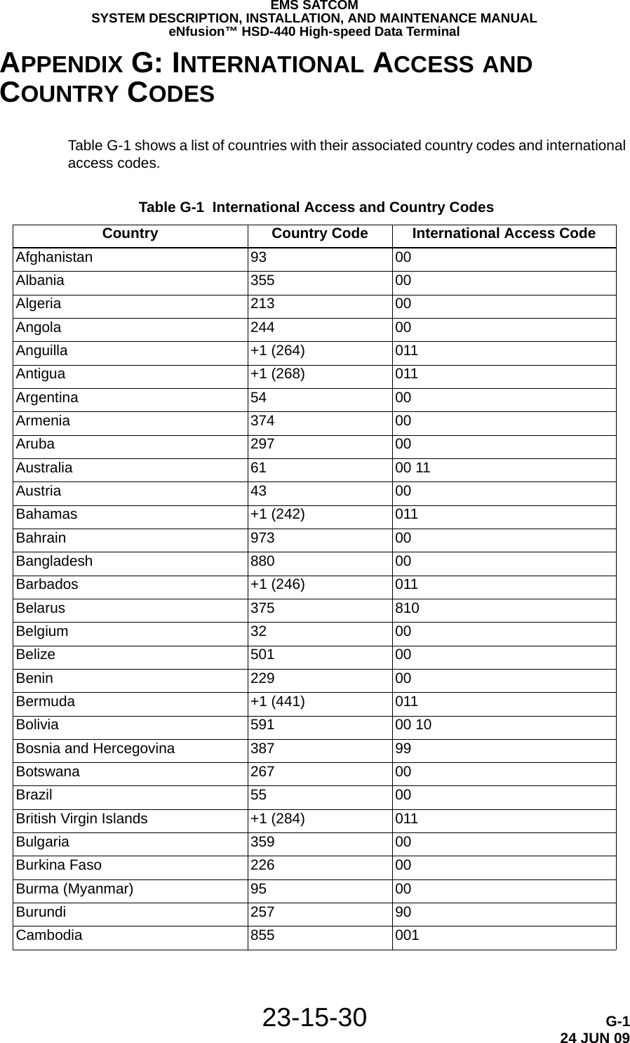
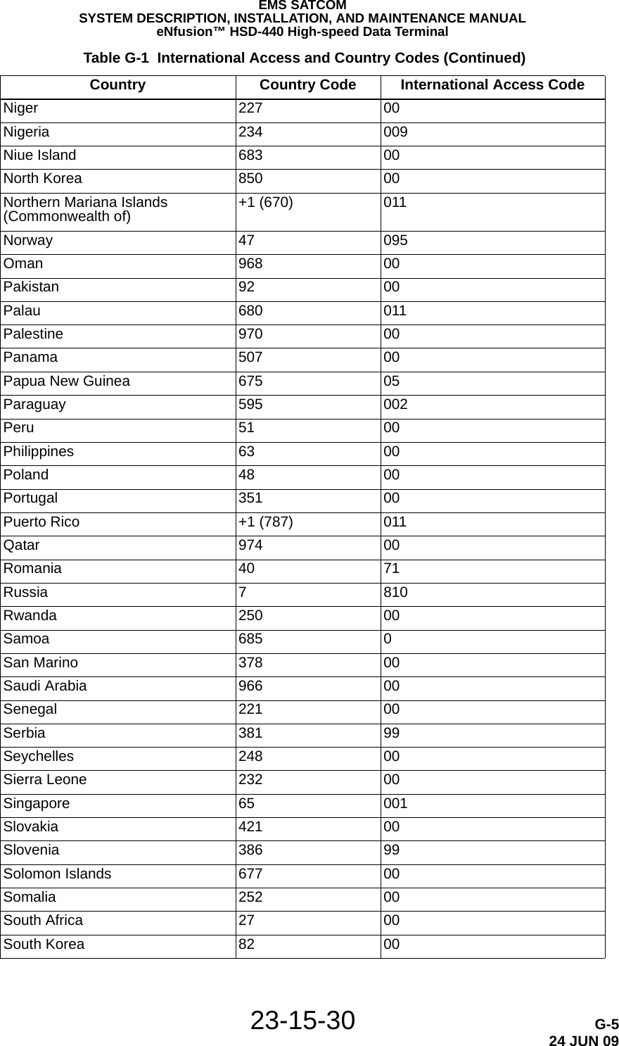
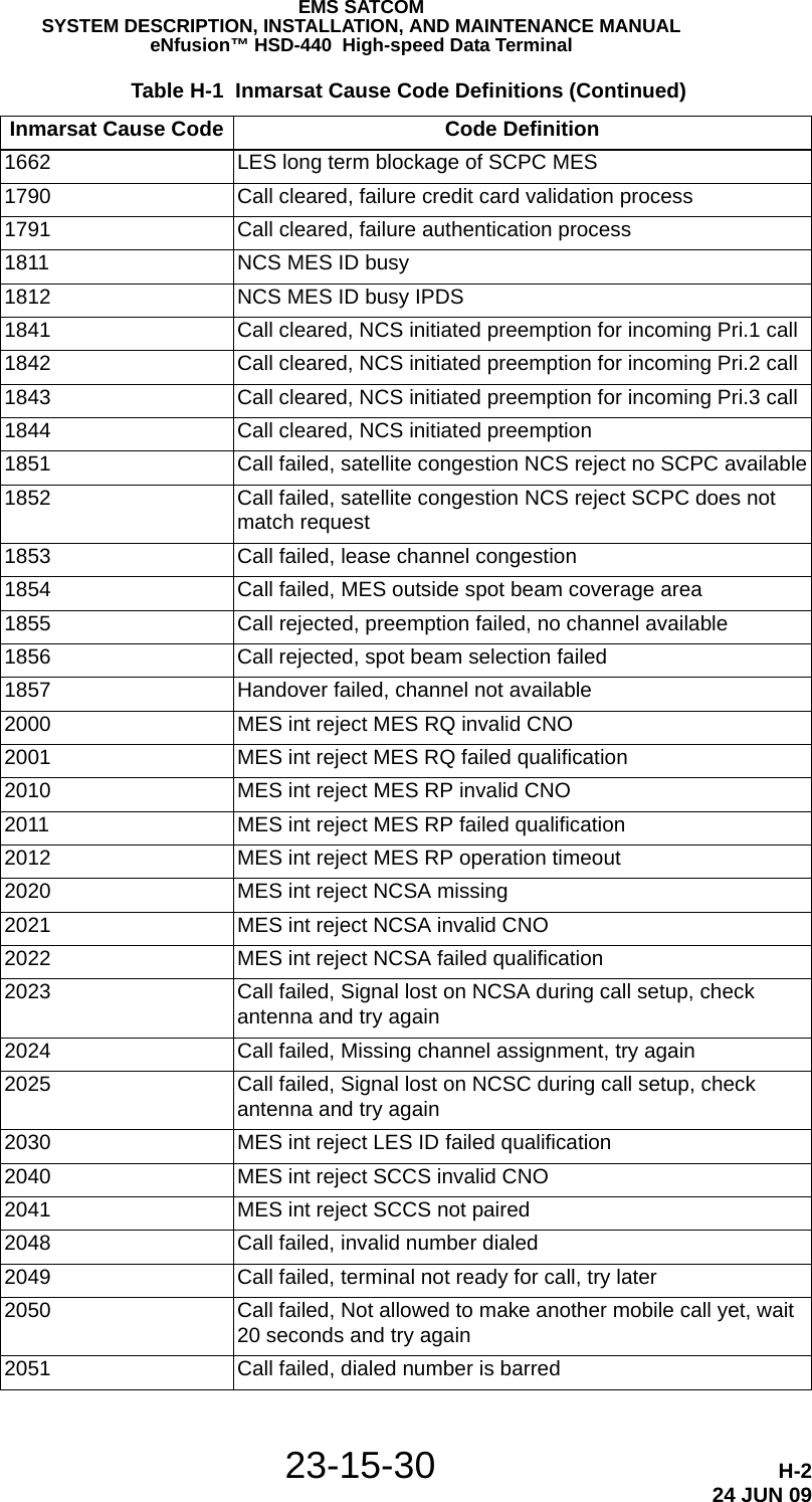
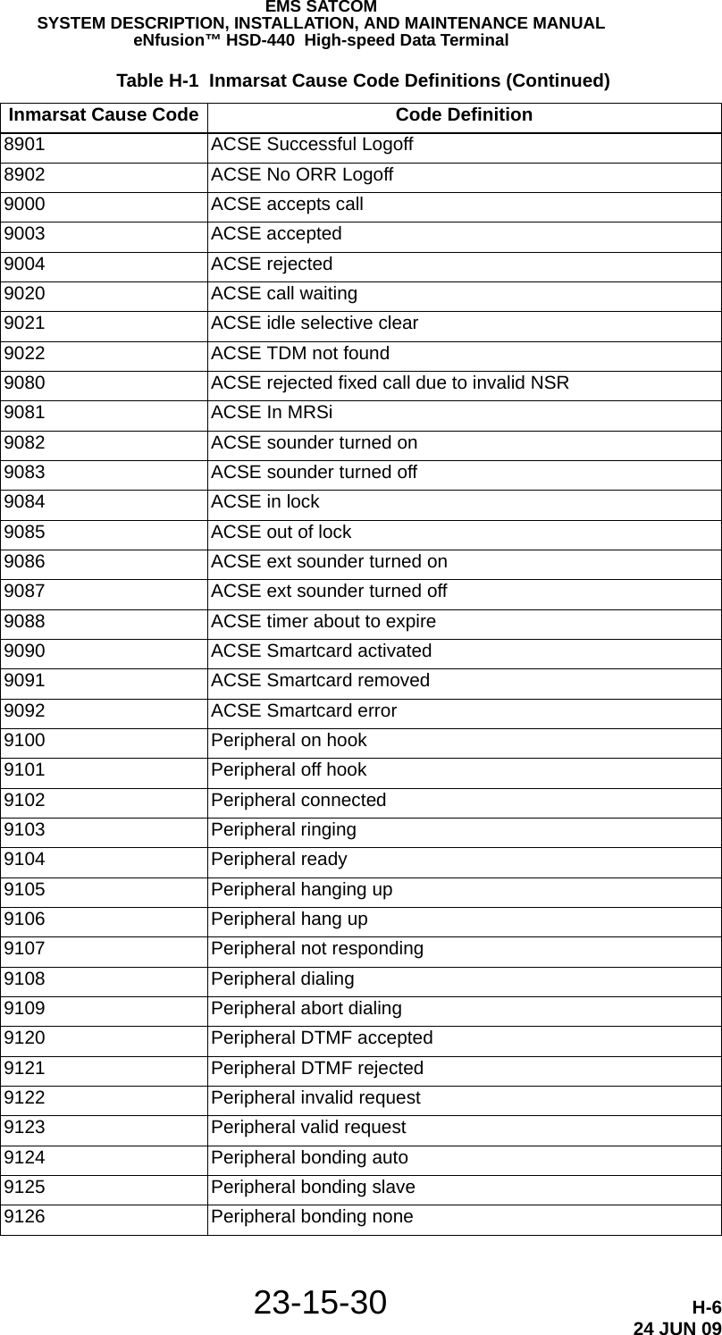
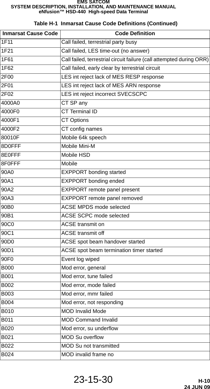
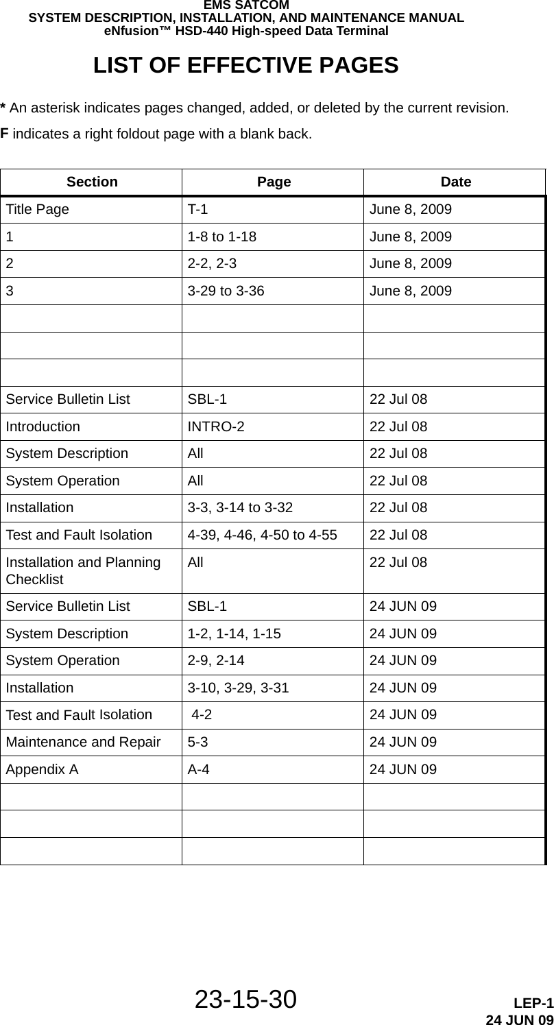
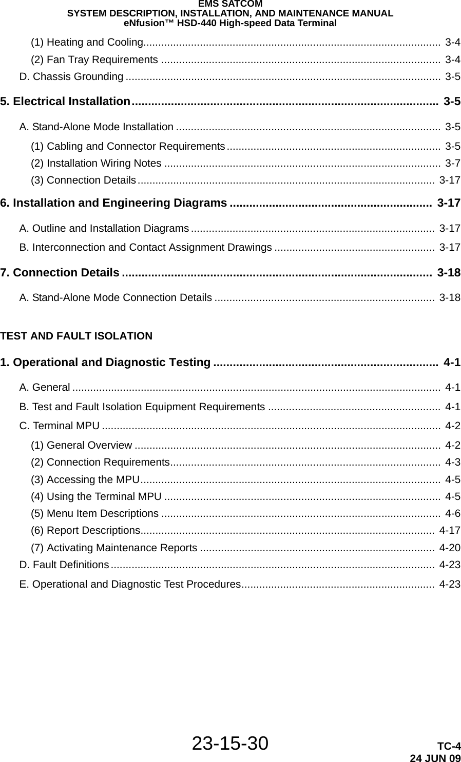
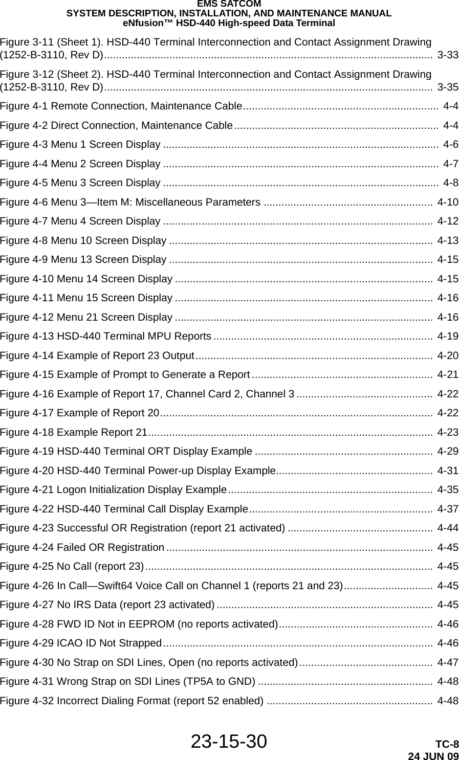
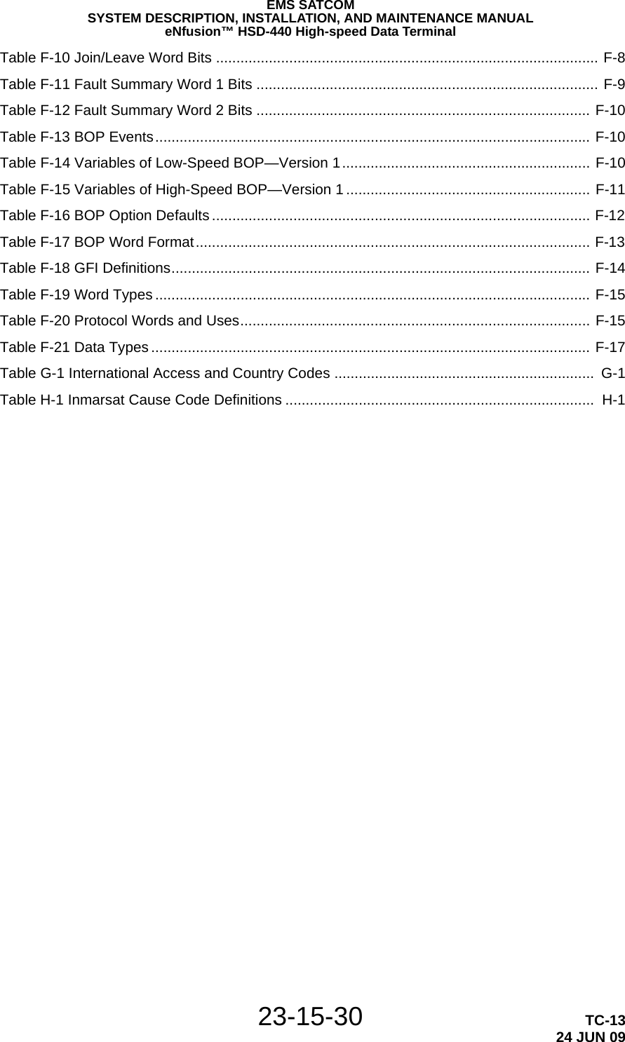
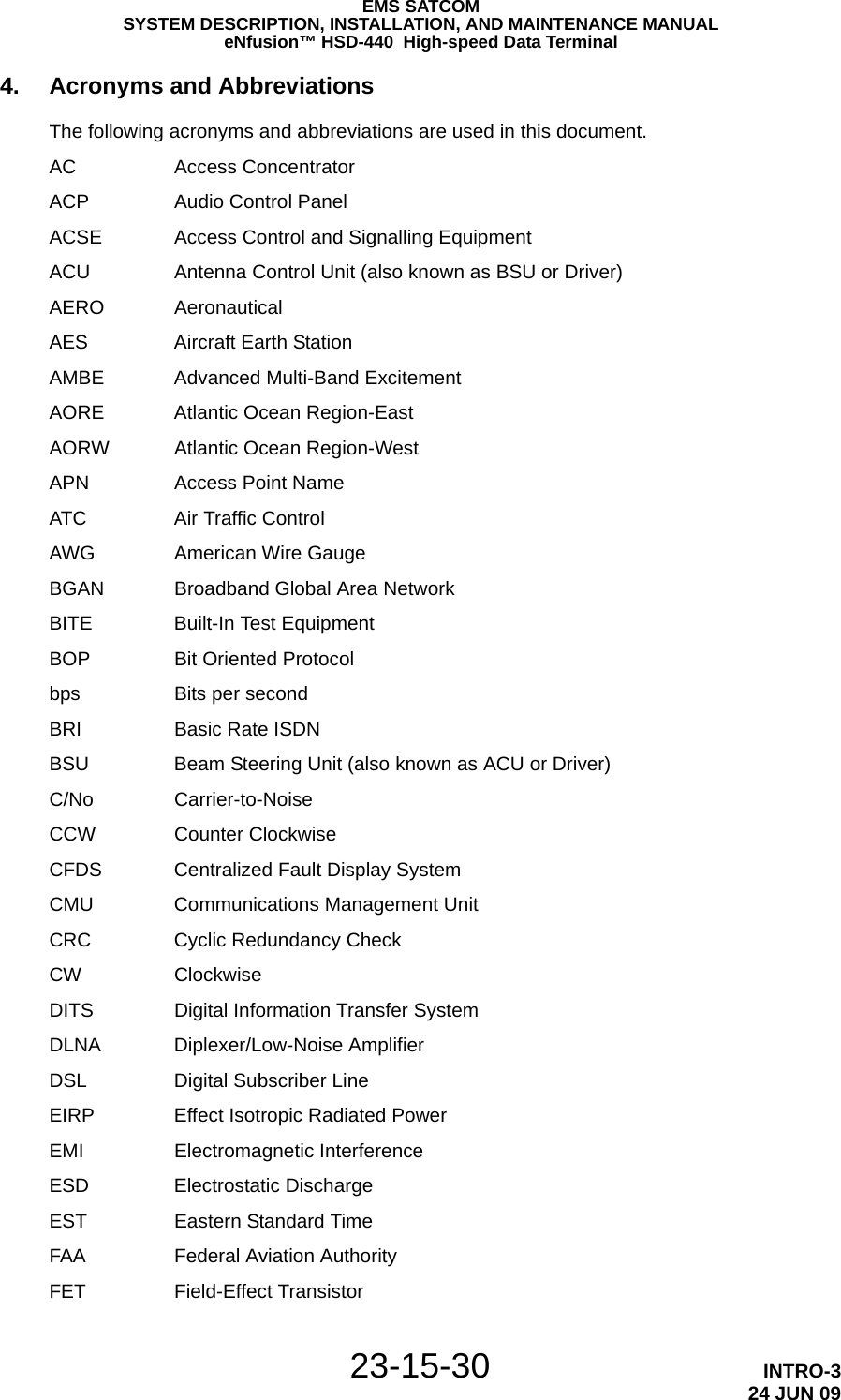
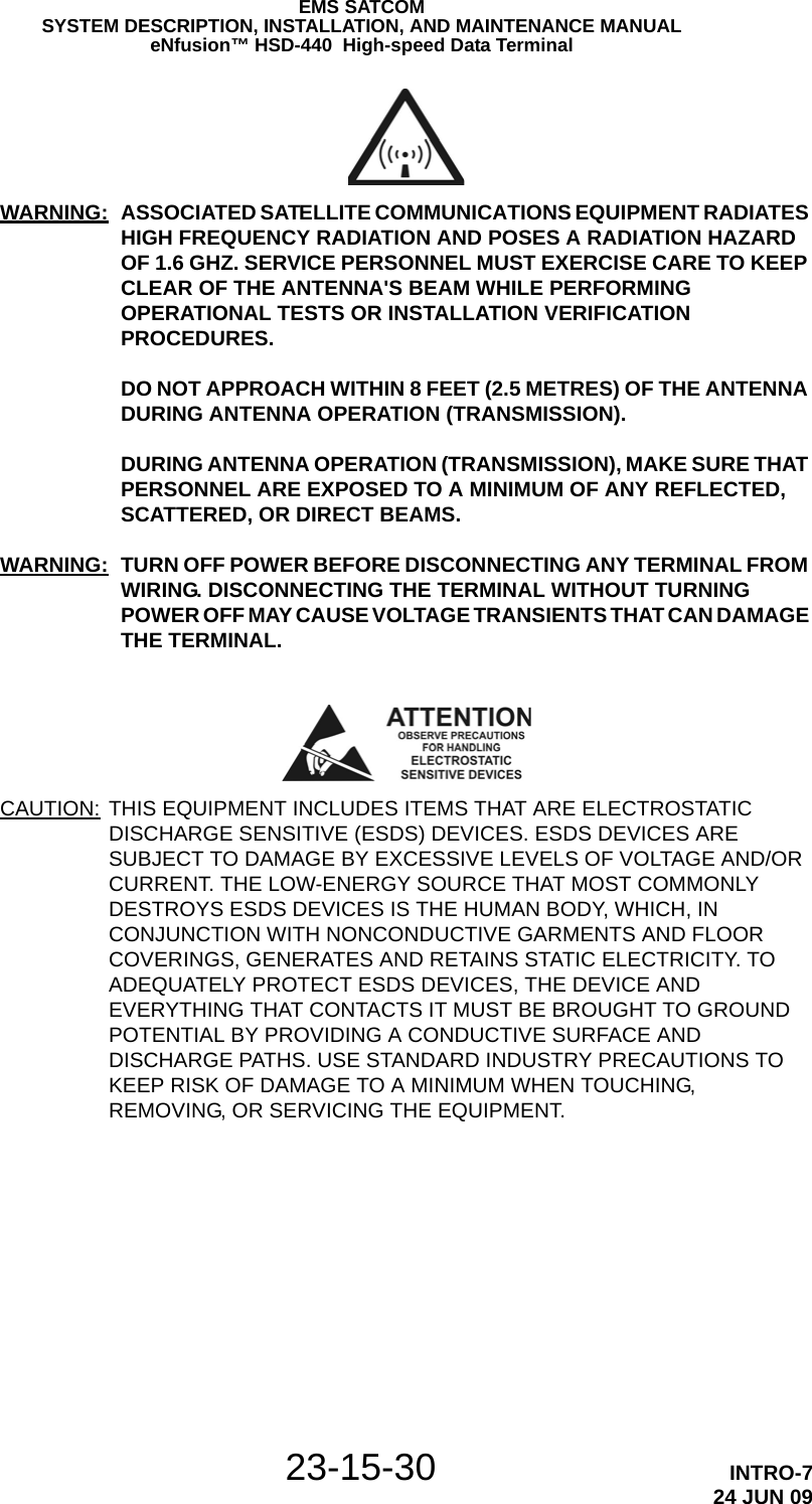
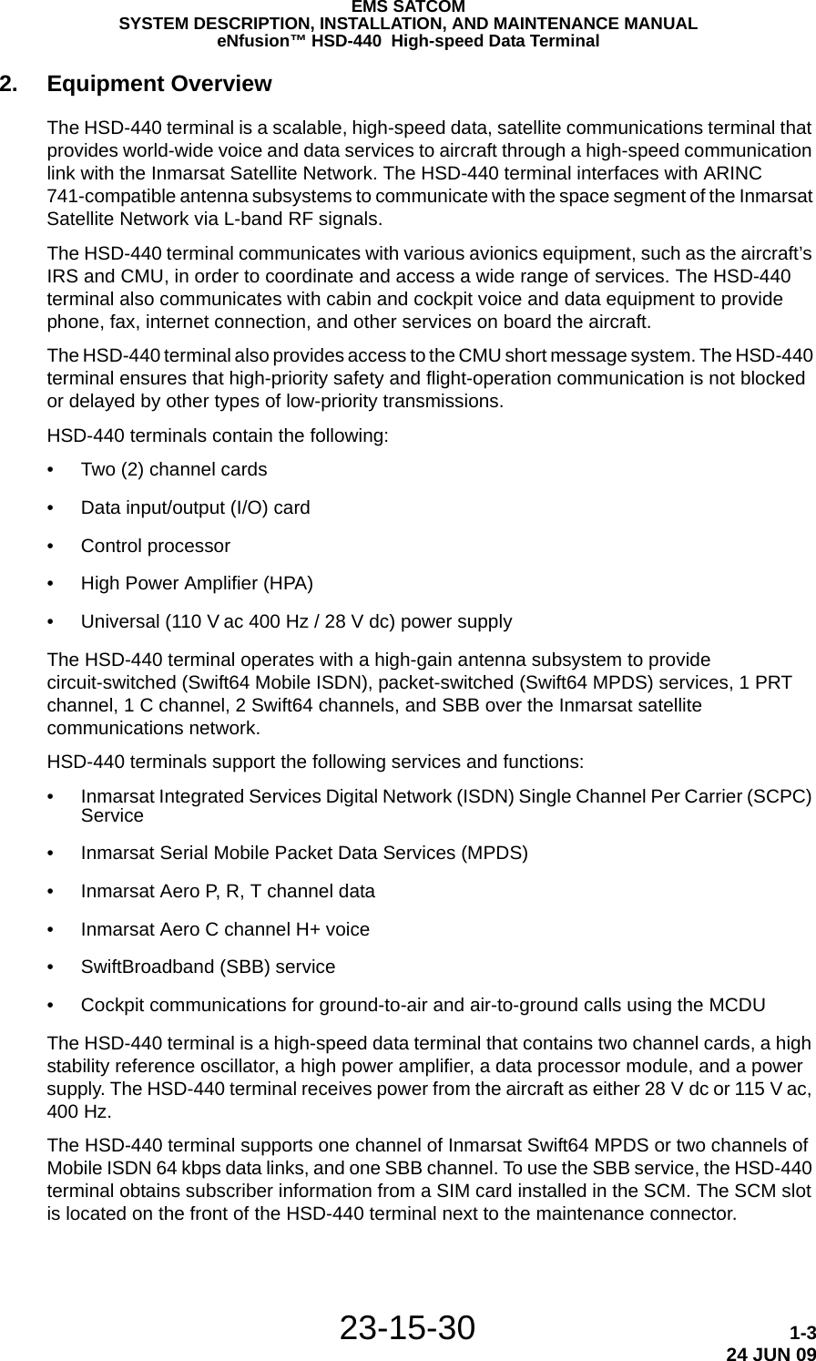
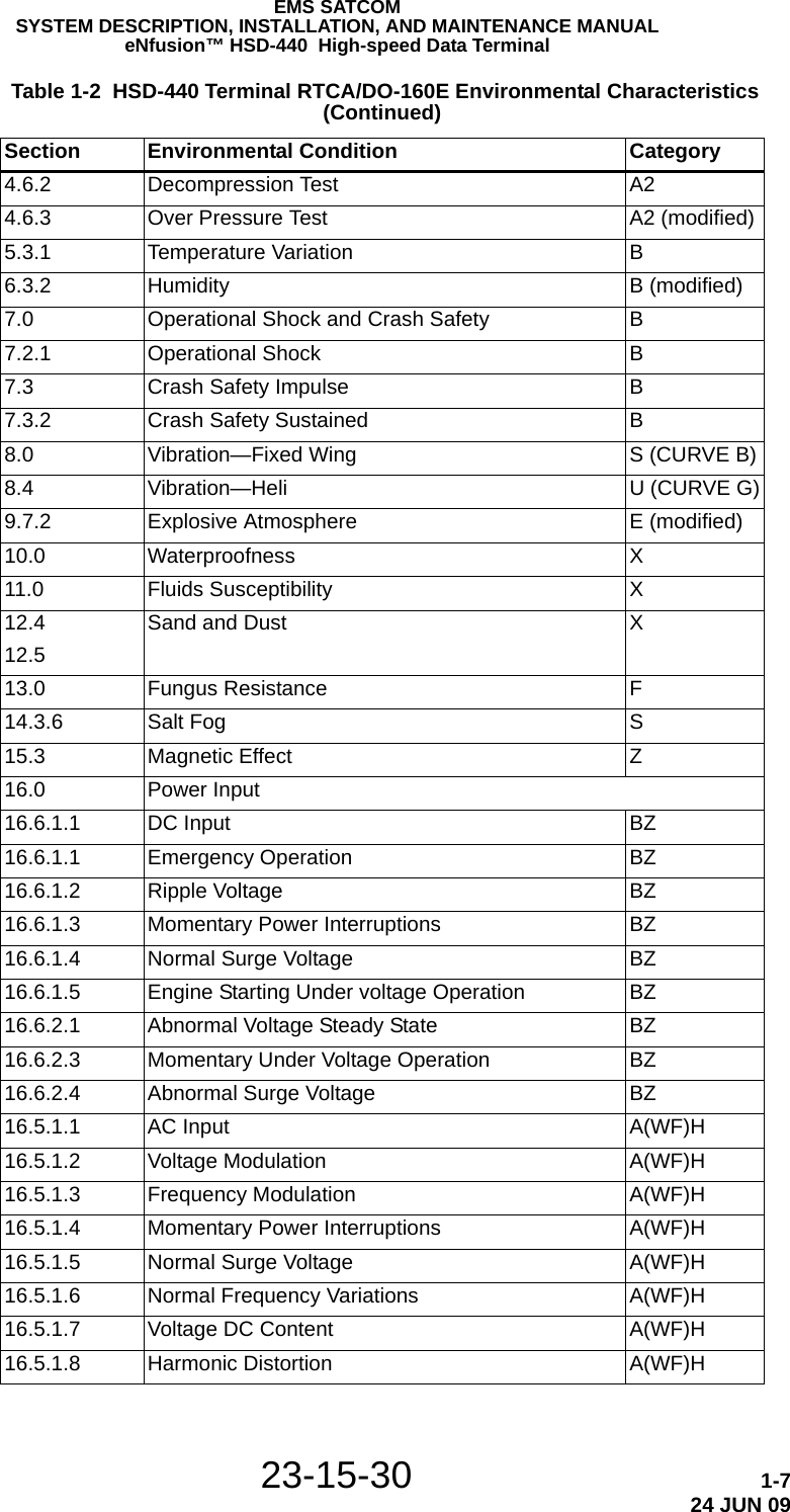
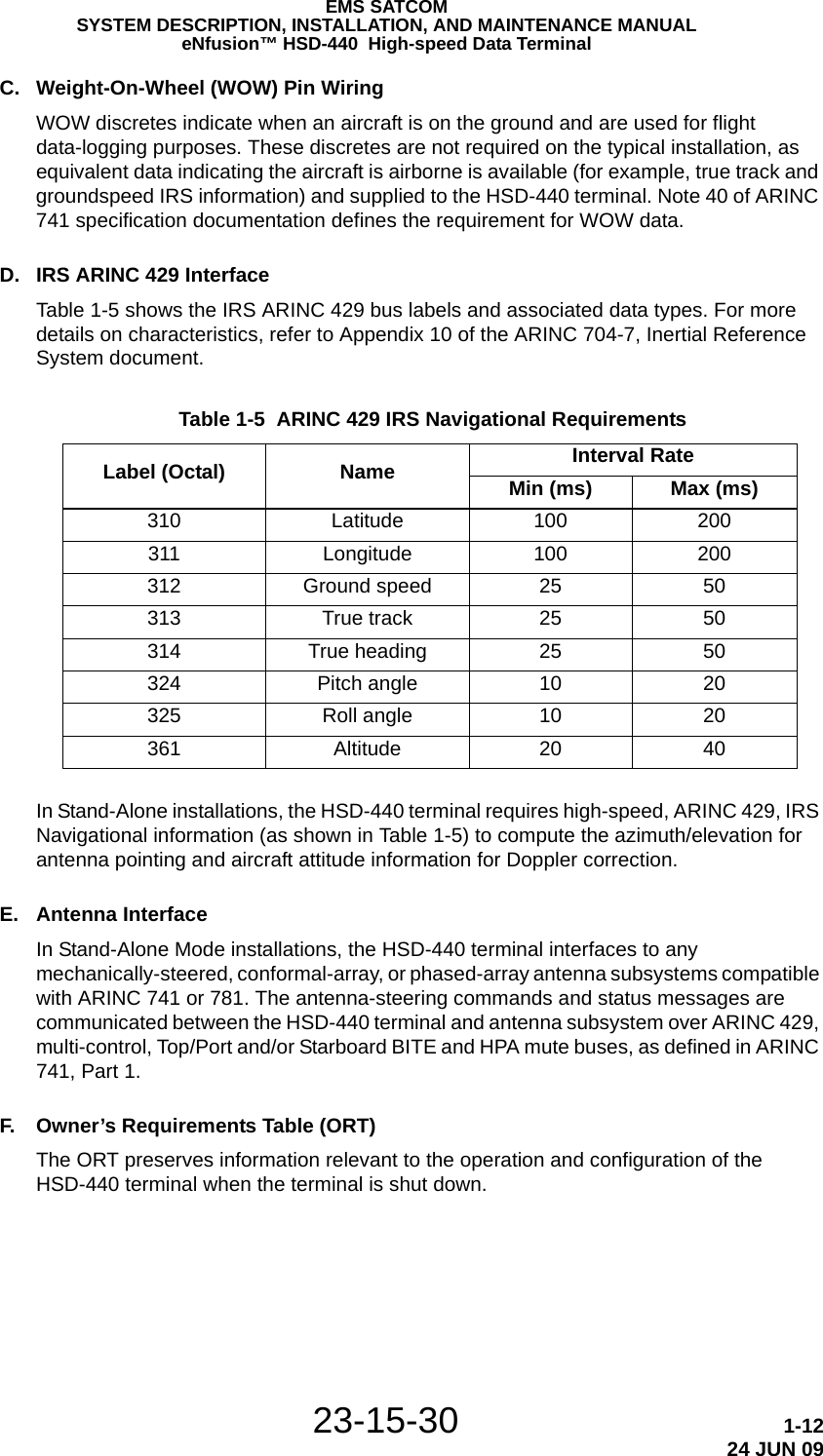
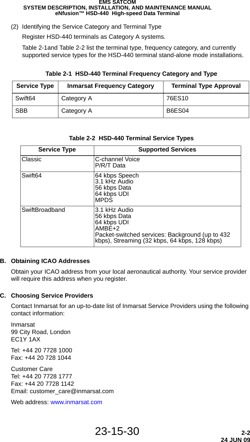
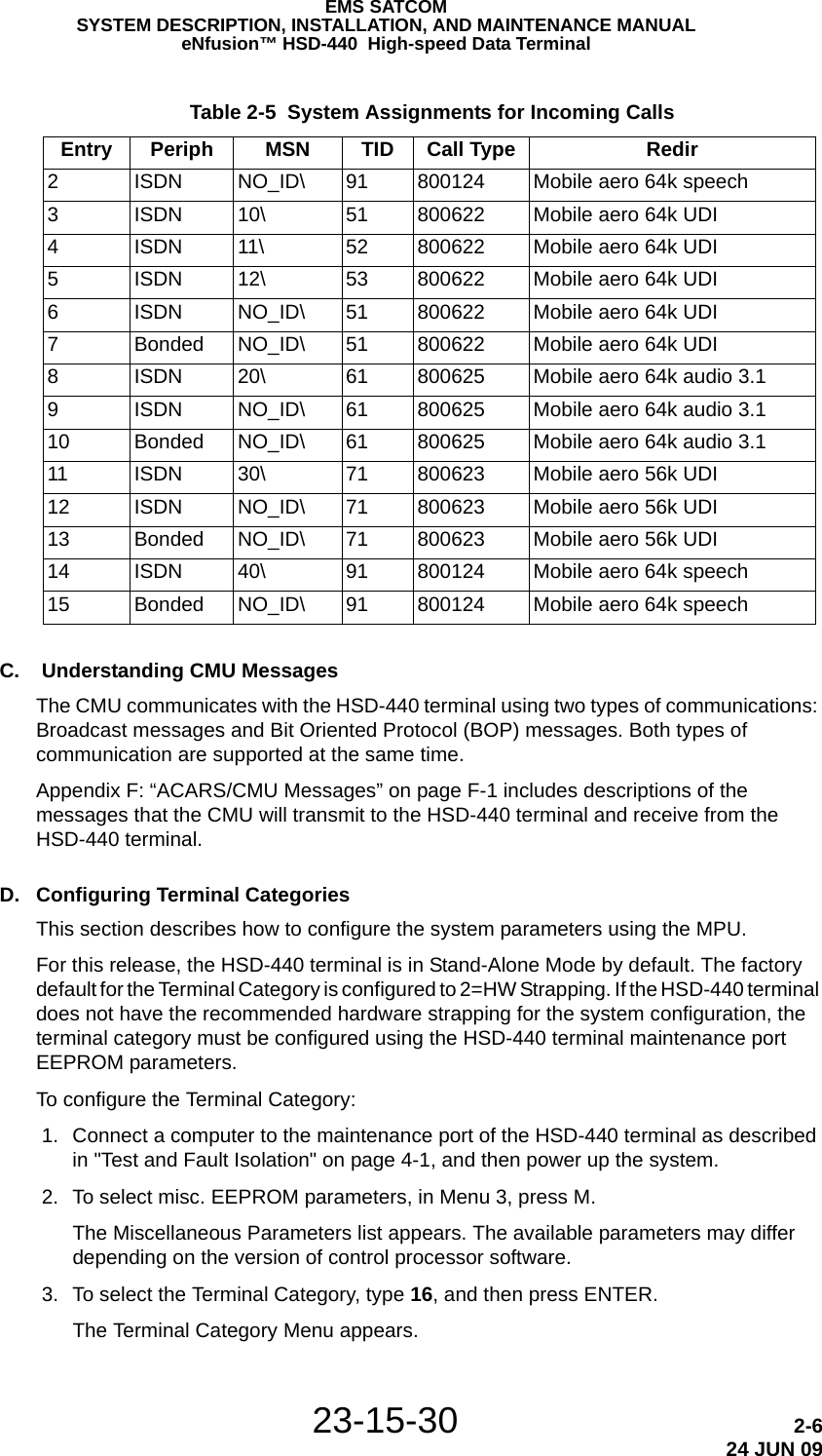
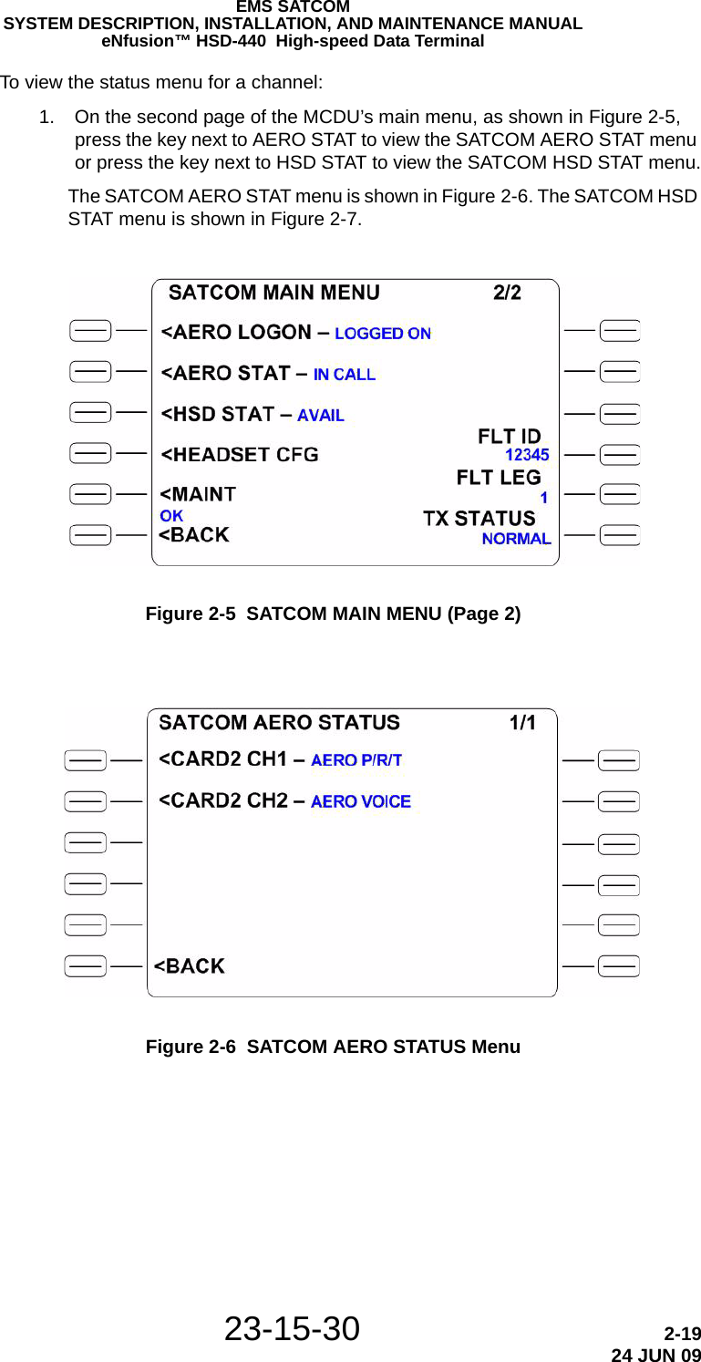
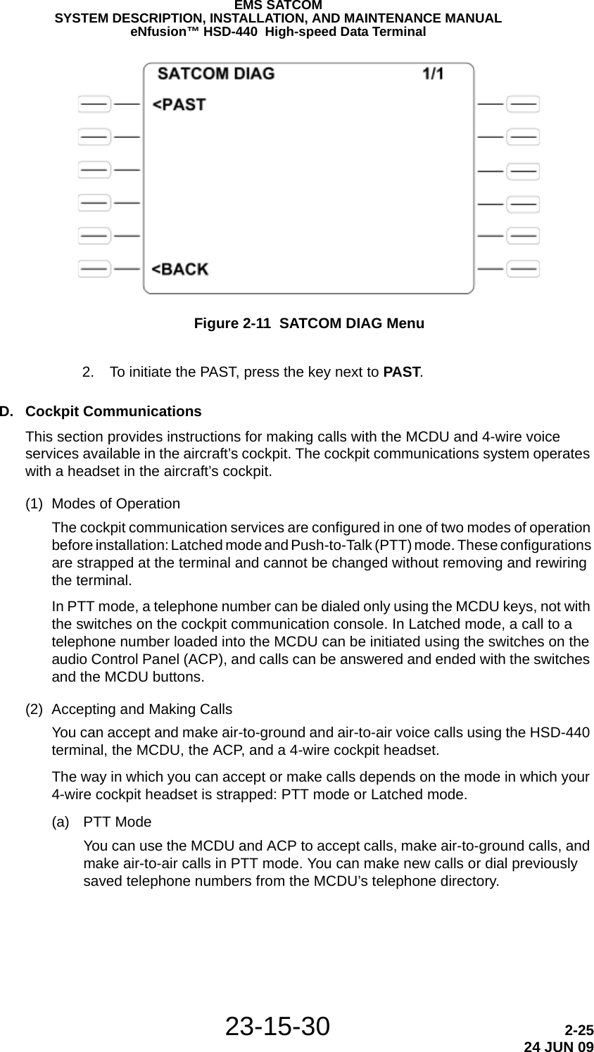
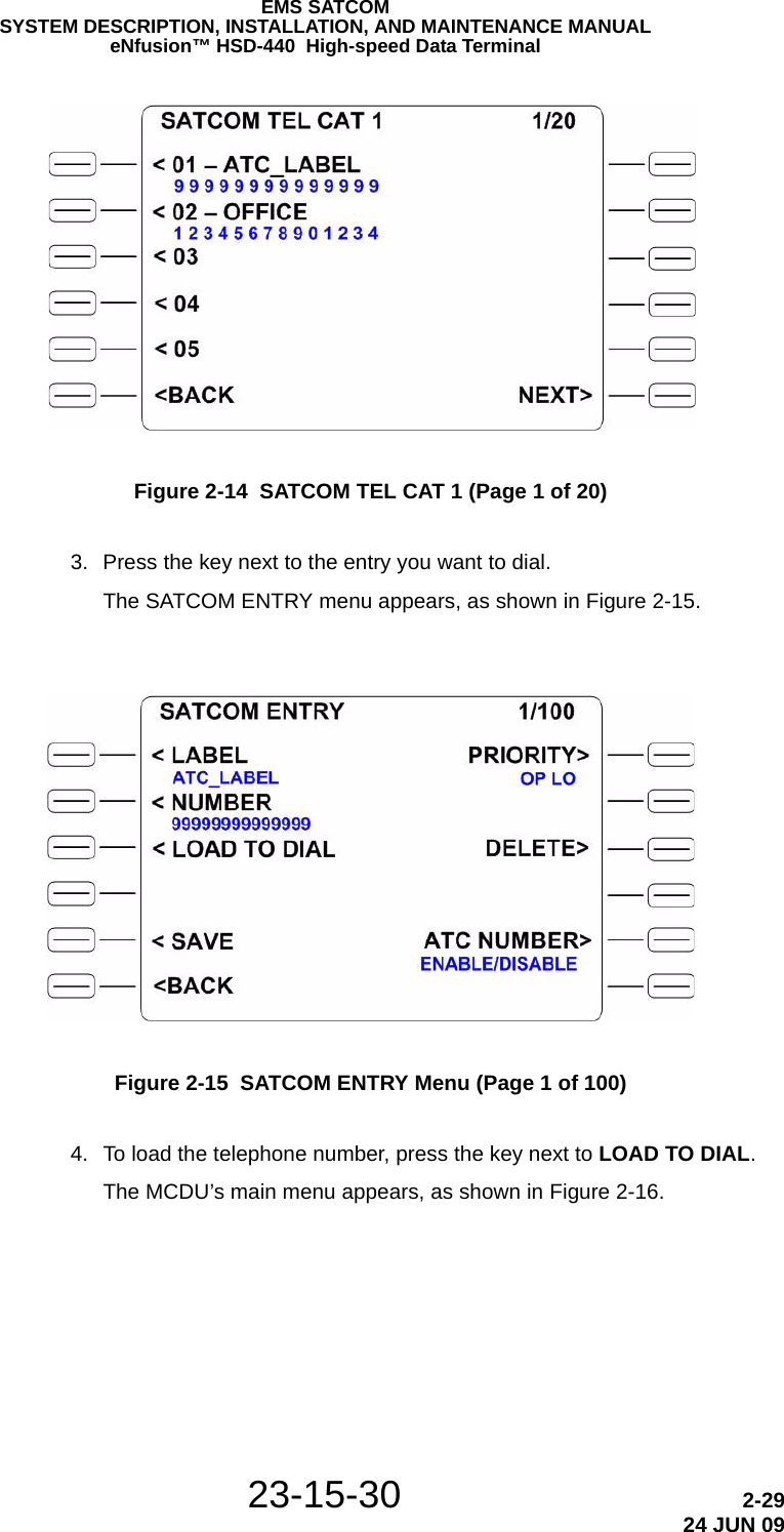
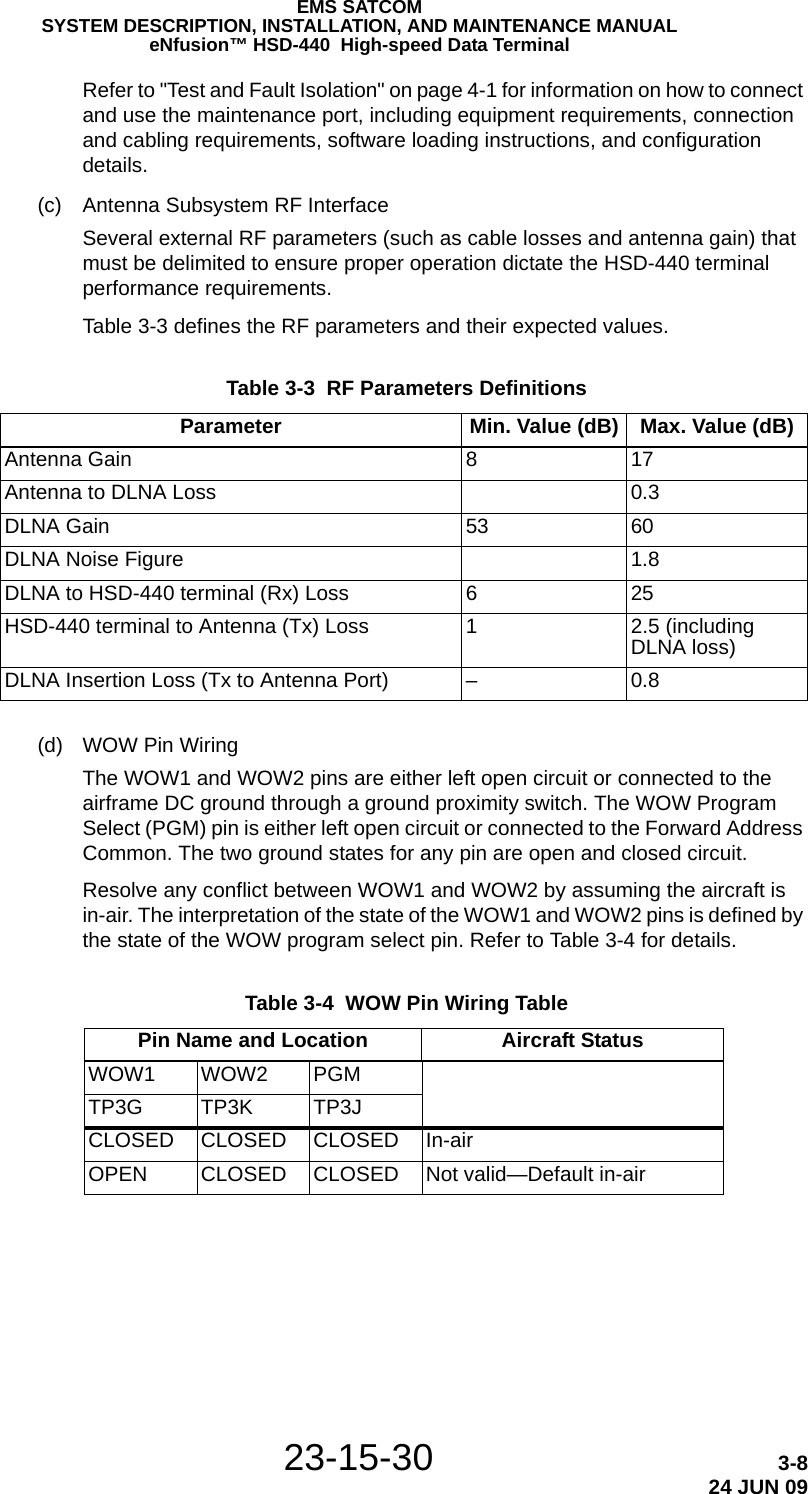
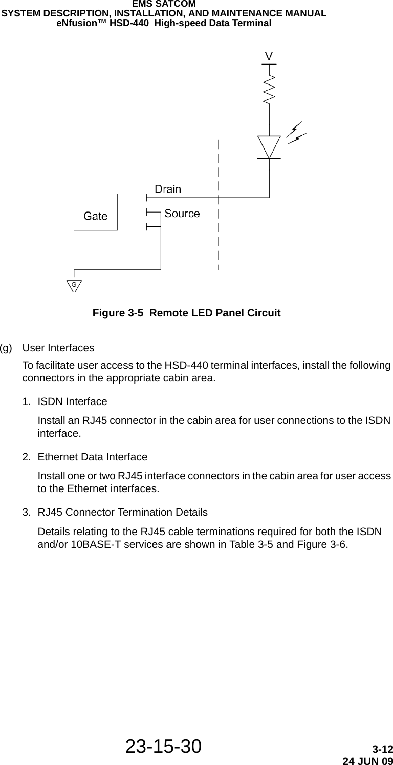
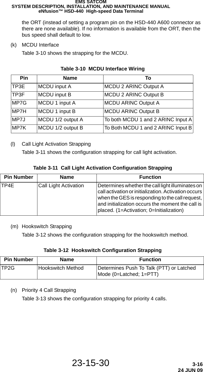
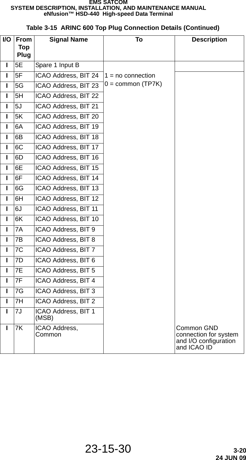
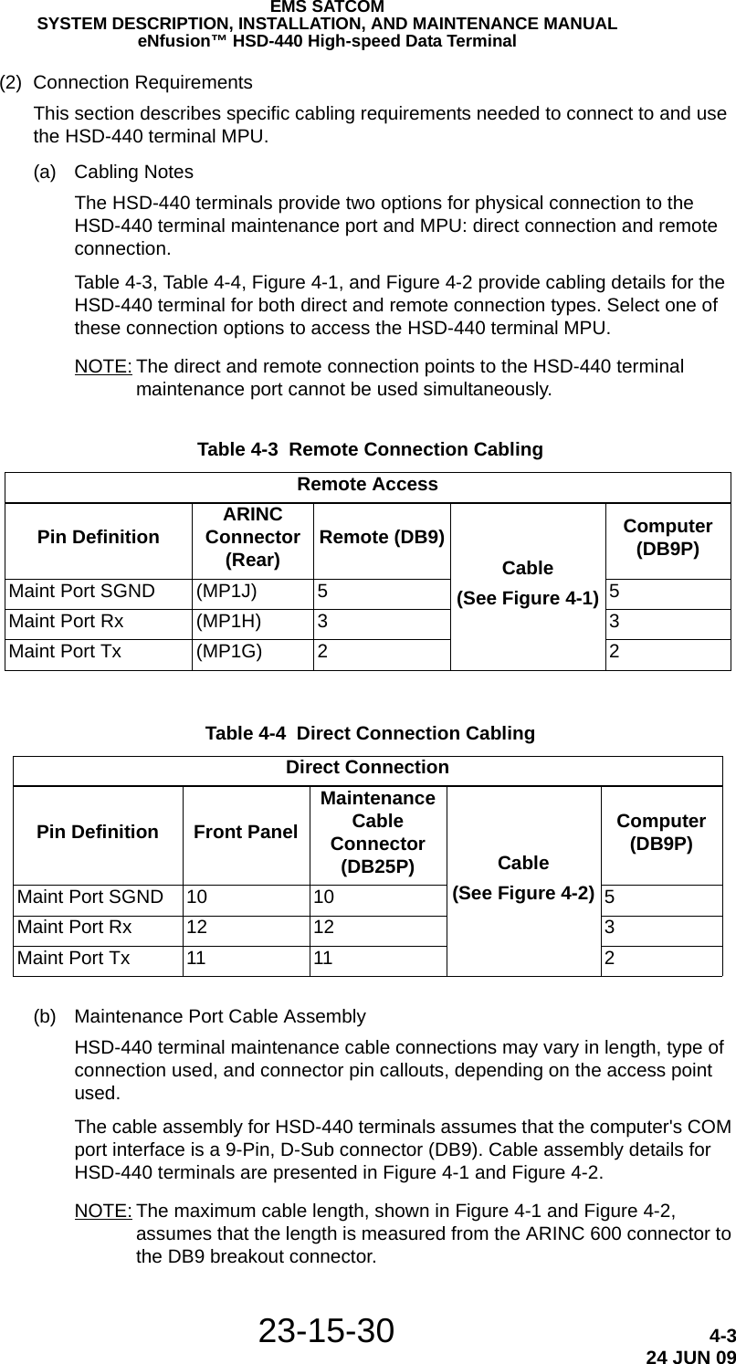
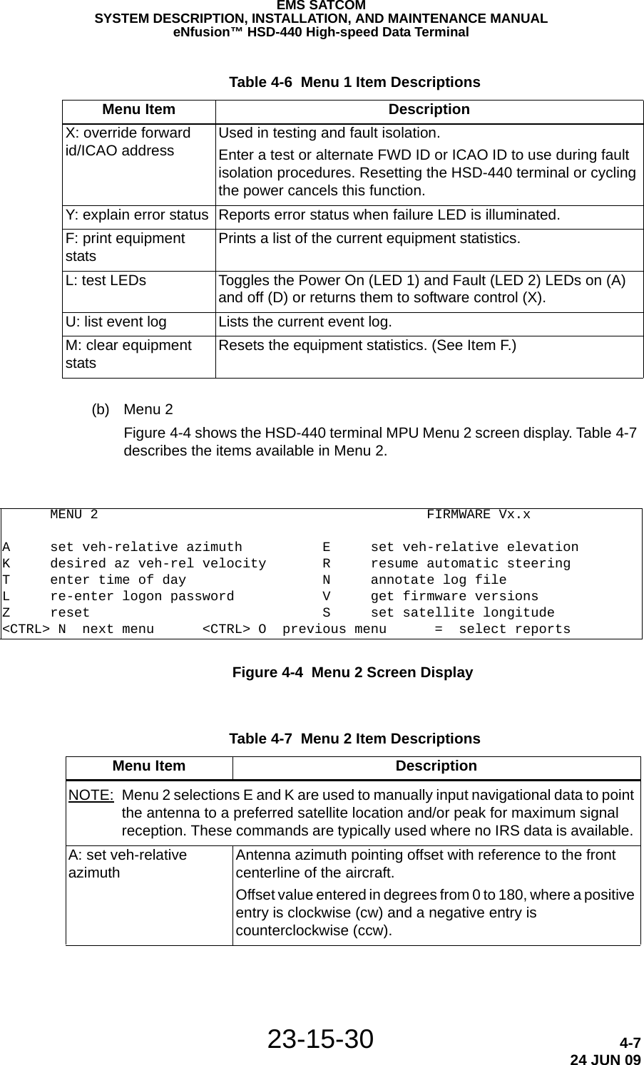
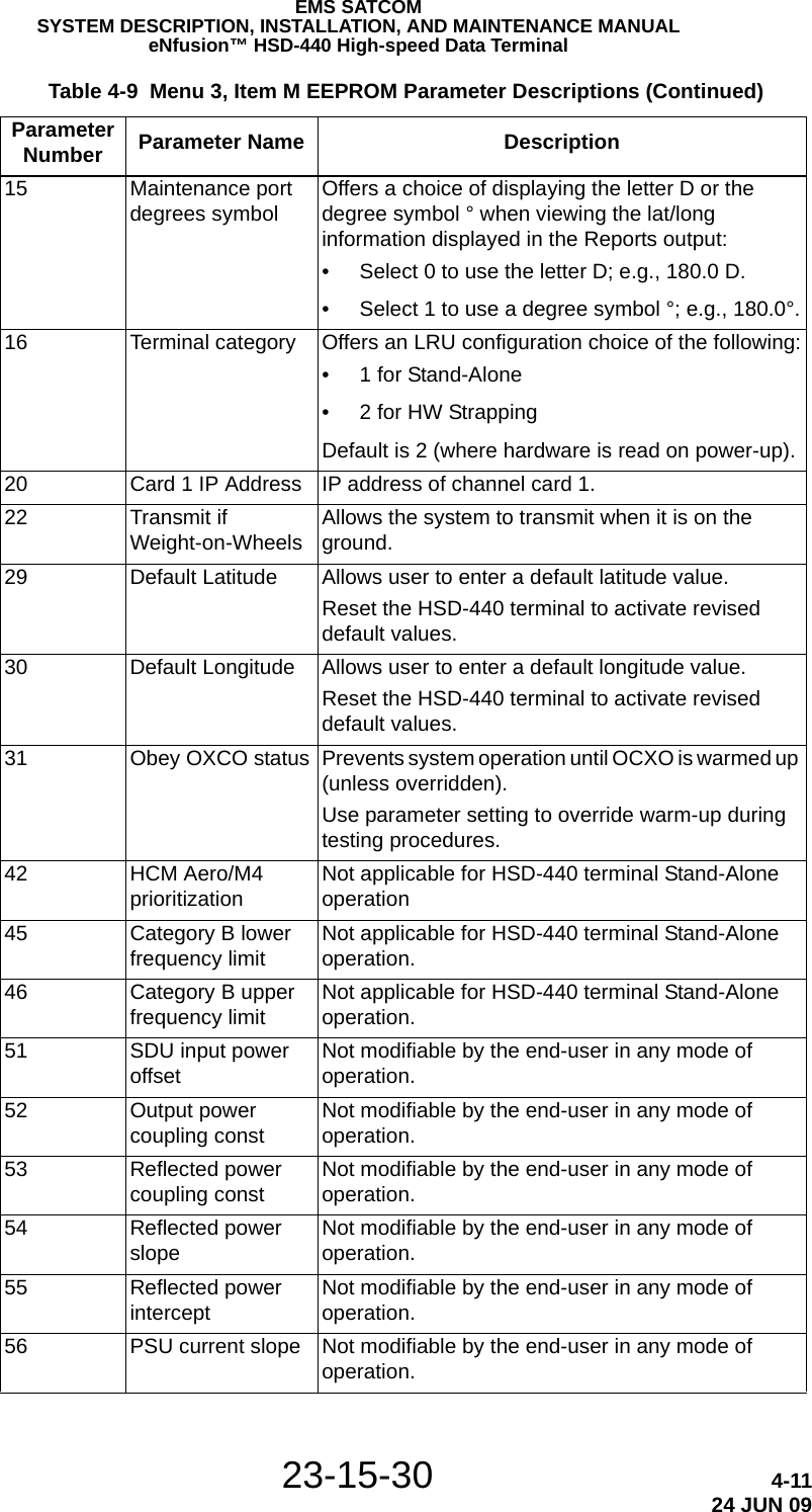
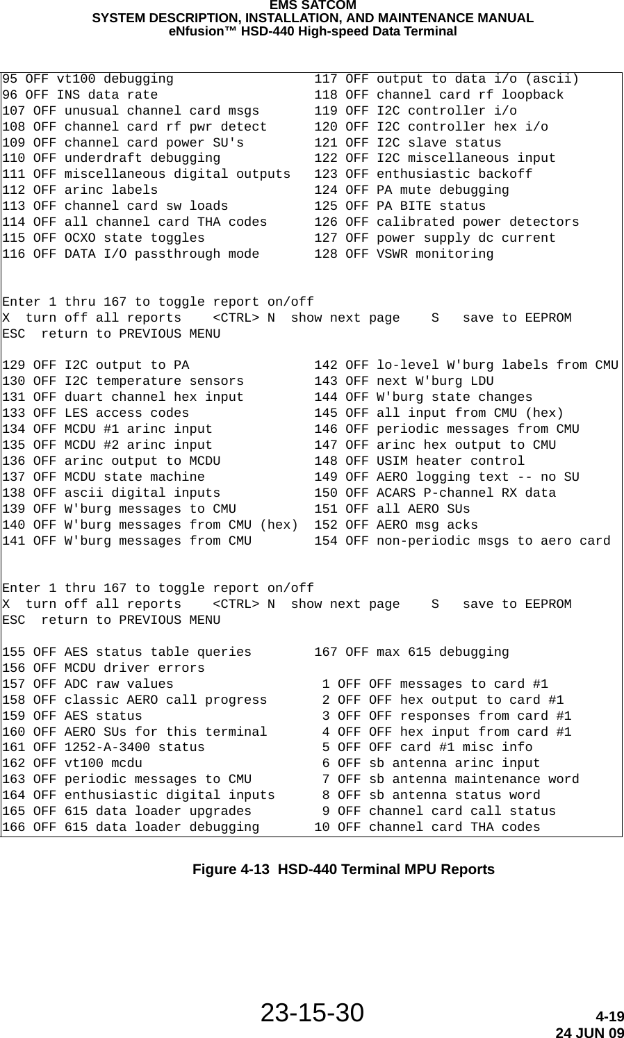
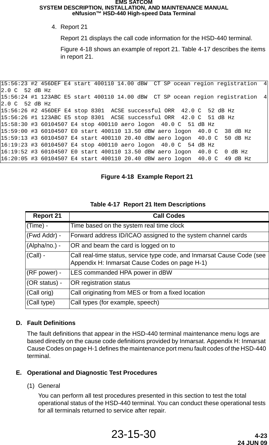
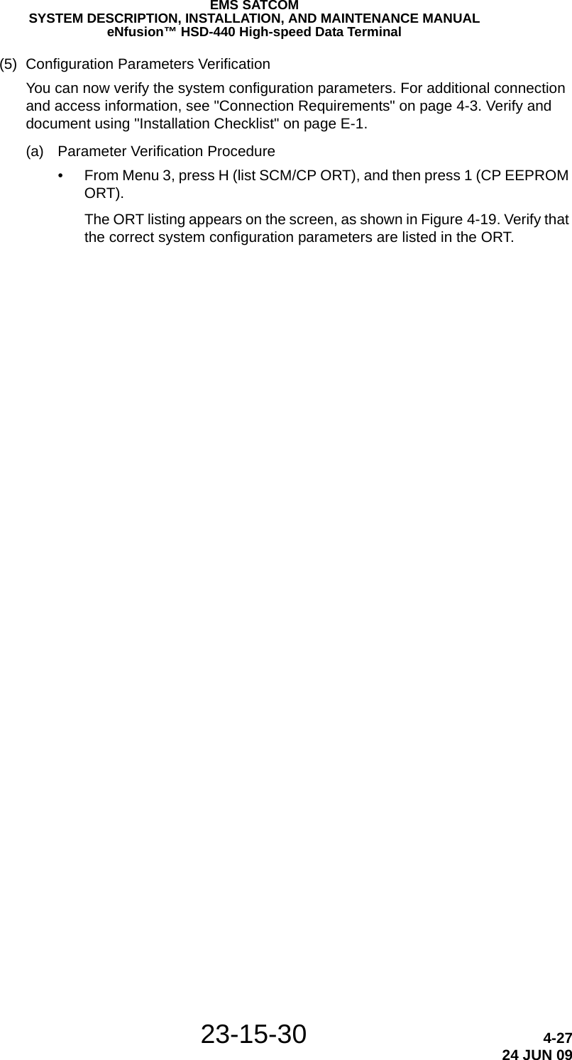
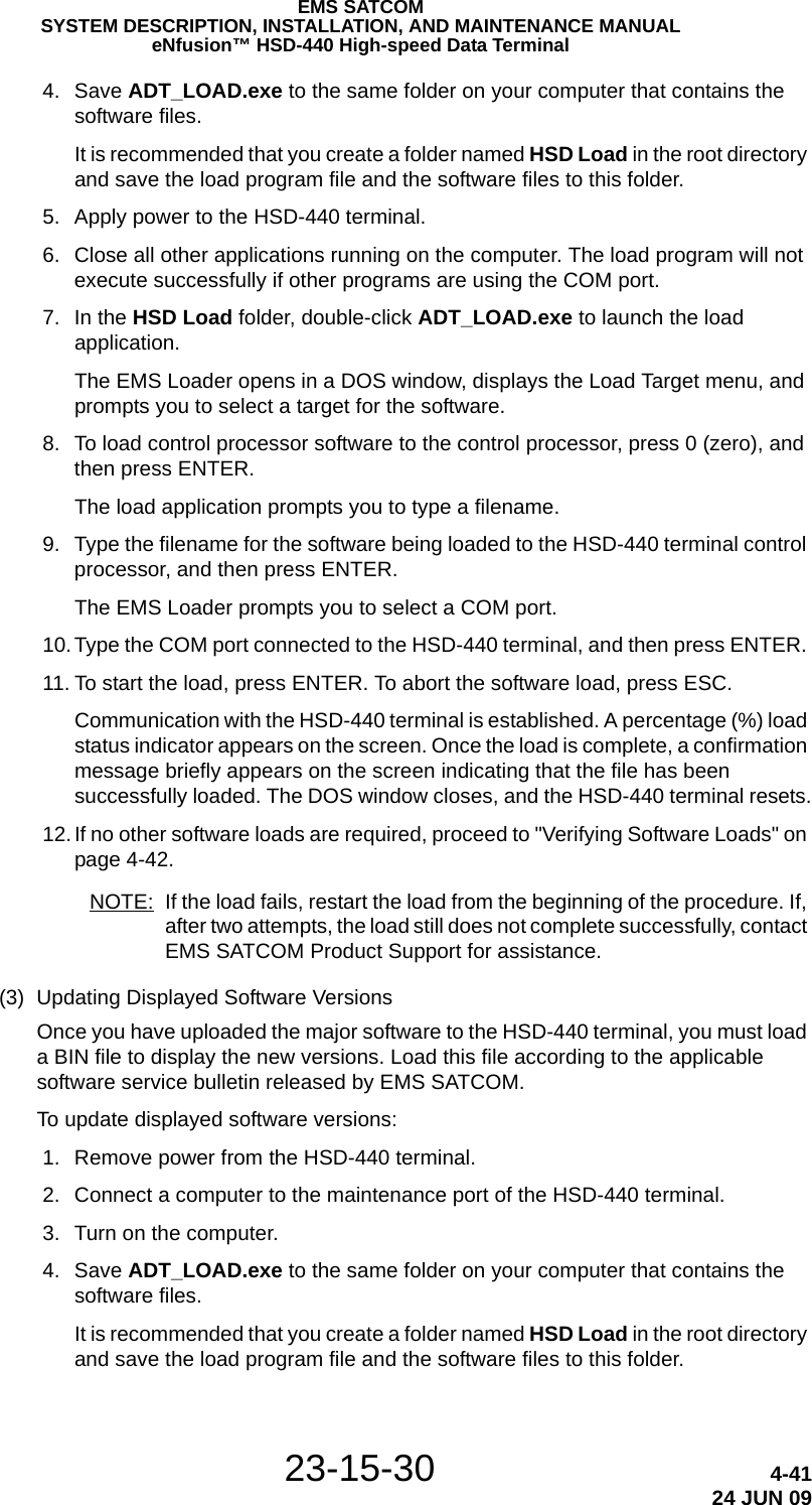
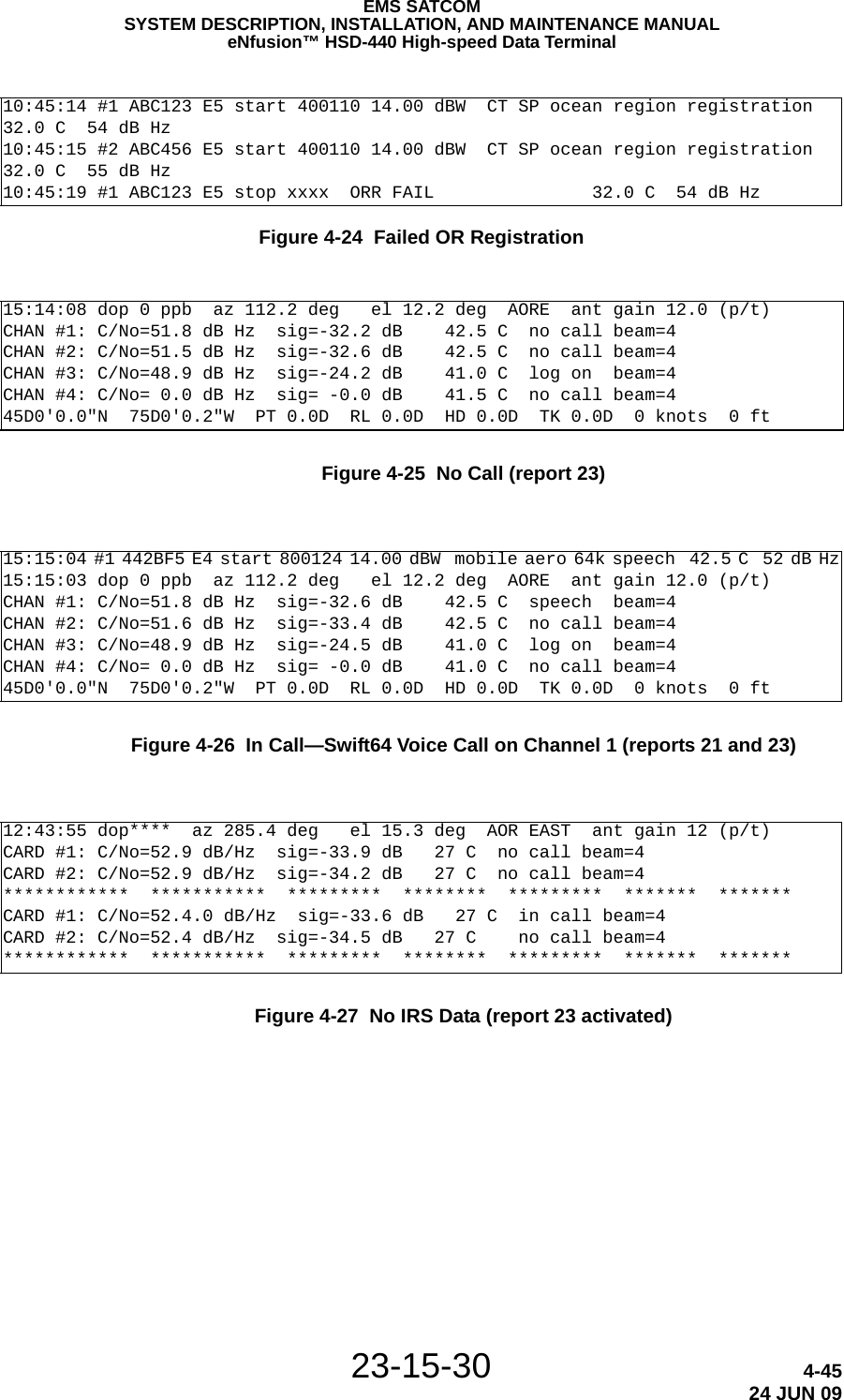
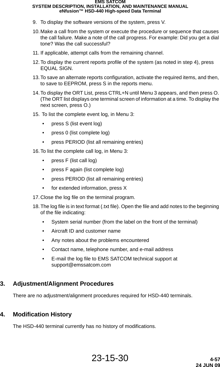
![23-15-30 2-1624 JUN 09EMS SATCOMSYSTEM DESCRIPTION, INSTALLATION, AND MAINTENANCE MANUALeNfusion™ HSD-440 High-speed Data Terminal• The CLR key: this key clears any text you type into the scratchpad.• The NEXT PAGE key: this key brings up the next page of a menu if one is available.You can program the other keys in the keyboard according to your requirements.(5) Special SymbolsBecause of space constraints on the screen, the MCDU uses a number of special symbols to indicate actions:•< and > appear at the far left or right to indicate that another menu page is available in that direction.•NUMBER/NUMBER appears to tell you which page out of how many pages you are viewing. For example, 1/2 would appear when you are on page 1 of 2 pages in total.•* appears when an action is associated with that key. For example, pushing the key beside the * could make a phone call, enter a password, or initiate a log off.•[ and ] appear around the first item in a list. Each instance of a list should be below a line item with a * beside it. You can push the key beside the * repeatedly to display the other items in the list. See ARINC 739A, section 3 and Attachment 10 for details.(6) Navigating the MCDUThe MCDU includes a number of menus, as shown in Figure 2-3.Figure 2-3 MCDU MenusThis section will help you perform the following tasks:•Modifying Logon Settings•Viewing Channel Status•Performing Maintenance](https://usermanual.wiki/EMS-Technologies-Canada/HSD-440/User-Guide-1257851-Page-66.png)


![23-15-30 4-3424 JUN 09EMS SATCOMSYSTEM DESCRIPTION, INSTALLATION, AND MAINTENANCE MANUALeNfusion™ HSD-440 High-speed Data TerminalCARD #2 LOGGING TEXT [02] 0922 ALO: Received user-initiated log on request (auto-select)CARD #2 LOGGING TEXT [00] 0923 ALO: User-initiated log on request ACCEPTEDCARD #2 LOGGING TEXT [02] 0924 ALO: State = Entry-11CARD #2 LOGGING TEXT [02] 0925 ALO: Searching priority group 5CARD #2 LOGGING TEXT [02] 0926 ALO: Sat ID 1, GES ID 68 not found in blacklistCARD #2 LOGGING TEXT [02] 0927 ALO: Number of valid satellites found in group = 1CARD #2 LOGGING TEXT [02] 0928 ALO: Satellite ID in view = 1CARD #2 LOGGING TEXT [02] 0929 ALO: Longitude difference from present position X100 = 6000CARD #2 LOGGING TEXT [02] 0930 ALO: Best satellite ID = 1CARD #2 LOGGING TEXT [02] 0931 ALO: State = Entry-2CARD #2 LOGGING TEXT [02] 0932 ALO: Pointing antenna: SatId=1 Gen=0 LongX100=-1500 Inc=0, RAsc=100CARD #2 LOGGING TEXT [02] 0933 ALO: Antenna pointing result = 1CARD #2 LOGGING TEXT [02] 0934 ALO: State = Entry-10CARD #2 LOGGING TEXT [02] 0935 ALO: Tuning Psid #0 to 14006CARD #2 LOGGING TEXT [05] 0936 ALO: Tuning P-channel(0) to 14006, rate=600, CommonTiming = 0CARD #2 LOGGING TEXT [05] 0937 ALO: Disable Tx Channels. R/T chan: 1CARD #2 LOGGING TEXT [02] 0938 ALO: State = Await P-Channel Sync-0CARD #2 LOGGING TEXT [34] 0939 DspMsg: P-status at t = 193 (fr = 0, sf = 0, uw 0)CARD #2 LOGGING TEXT [34] 0940 DspMsg: P-ch acquisition initiated at t = 19317:06:20 #2 DEF456 E5 start 400110 14.00 dBW CT SP ocean region registration 41.5 C 0 dB Hz17:06:20 #1 ABC123 E4 start 400110 14.00 dBW CT SP ocean region registration 41.5 C 0 dB Hz17:06:22 #1 ABC123 E4 start 400110 14.00 dBW CT SP ocean region registration 41.5 C 0 dB Hz17:06:22 #2 DEF456 E5 start 400110 14.00 dBW CT SP ocean region registration 41.5 C 0 dB Hz17:06:23 #1 ABC123 E4 start 400110 14.00 dBW CT SP ocean region registration 41.5 C 0 dB Hz17:06:23 #2 DEF456 E5 start 400110 14.00 dBW CT SP ocean region registration 41.5 C 0 dB HzCARD #2 LOGGING TEXT [34] 0947 DspMsg: P-status at t = 199 (fr = 1, sf = 0, uw 0)CARD #2 LOGGING TEXT [34] 0948 DspMsg: P-ch sync acquired at t = 199CARD #2 LOGGING TEXT [02] 0949 ALO: State = Await Revision Number17:06:25 #1 ABC123 E4 start 400110 14.00 dBW CT SP ocean region registration 41.5 C 0 dB Hz17:06:25 #2 DEF456 E5 start 400110 14.00 dBW CT SP ocean region registration 41.5 C 0 dB HzCARD #2 LOGGING TEXT [34] 0950 DspMsg: P-status at t = 200 (fr = 1, sf = 0, uw 1)CARD #2 LOGGING TEXT [02] 0952 ALO: Detected System Table revision 57CARD #2 LOGGING TEXT [02] 0953 ALO: No System Table update required17:06:27 #2 DEF456 E5 start 400110 14.00 dBW CT SP ocean region registration 41.5 C 0 dB Hz17:06:27 #1 ABC123 E4 start 400110 14.00 dBW CT SP ocean region registration 41.5 C 0 dB HzCARD #2 LOGGING TEXT [02] 0959 ALO: Spot Beam Map revision 1 - no update requiredCARD #2 LOGGING TEXT [02] 0960 ALO: State = Entry-3CARD #2 LOGGING TEXT [02] 0961 ALO: At entry-3 with null GES ID and satellite chosen from the ORT; check ORT for corresponding GESCARD #2 LOGGING TEXT [02] 0962 ALO: Sat ID 1, GES ID 68 not found in blacklistCARD #2 LOGGING TEXT [02] 0963 ALO: Sat ID 1, GES ID 67 not found in blacklistCARD #2 LOGGING TEXT [02] 0964 ALO: Sat ID 1, GES ID 65 not found in blacklistCARD #2 LOGGING TEXT [02] 0965 ALO: Adding to blacklist at index 0, sat ID 1, GES ID 65CARD #2 LOGGING TEXT [02] 0966 ALO: For sat ID 1 in ORT group 5, number of valid GESs available = 2CARD #2 LOGGING TEXT [02] 0967 ALO: Selected GES ID = 68CARD #2 LOGGING TEXT [02] 0968 ALO: AES is in beam 4CARD #2 LOGGING TEXT [02] 0969 ALO: Tuning Psmc to 14078CARD #2 LOGGING TEXT [05] 0970 ALO: Tuning P-channel(0) to 14078, rate=600, CommonTiming = 0CARD #2 LOGGING TEXT [05] 0971 ALO: Disable Tx Channels. R/T chan: 1CARD #2 LOGGING TEXT [02] 0972 ALO: Requesting Rsmc power for chnl 1: eirp_X100 = 1350, min_slot = 14022, max slot = 1403817:06:27 #3 60104507 E0 start 400110 13.50 dBW aero logon 40.0 C 36 dB HzCARD #2 LOGGING TEXT [02] 0973 ALO: State = Await P-Channel Sync-1CARD #2 LOGGING TEXT [34] 0974 DspMsg: P-status at t = 201 (fr = 0, sf = 0, uw 0)CARD #2 LOGGING TEXT [34] 0975 DspMsg: P-ch acquisition initiated at t = 201CARD #2 LOGGING TEXT [02] 0976 ALO: Rsmc power allocated: EIRP requested = 1350, allocated = 135017:06:29 #1 ABC123 E4 start 400110 14.00 dBW CT SP ocean region registration 41.5 C 0 dB Hz17:06:29 #2 DEF456 E5 start 400110 14.00 dBW CT SP ocean region registration 41.5 C 0 dB Hz17:06:31 #1 ABC123 E4 start 400110 14.00 dBW CT SP ocean region registration 41.5 C 0 dB Hz17:06:31 #2 DEF456 E5 start 400110 14.00 dBW CT SP ocean region registration 41.5 C 0 dB HzCARD #2 LOGGING TEXT [34] 0980 DspMsg: P-status at t = 207 (fr = 1, sf = 0, uw 0)CARD #2 LOGGING TEXT [34] 0981 DspMsg: P-ch sync acquired at t = 207CARD #2 LOGGING TEXT [02] 0982 ALO: Tuning RsmcCARD #2 LOGGING TEXT [05] 0983 ALO: Tuning R-channel(1) to 14038, rate=600, eirp_X100=1350CARD #2 LOGGING TEXT [06] 0984 DEA: Msg: Log onCARD #2 LOGGING TEXT [02] 0985 ALO: State = Entry-5CARD #2 LOGGING TEXT [02] 0986 ALO: Sending log on request to GES 68 for class 3 AES in beam 4CARD #2 LOGGING TEXT [02] 0987 ALO: State = Await Log-On ConfirmCARD #2 LOGGING TEXT [0b] 0988 LLUSER: Log-on in progress AMIDU17:06:33 #1 ABC123 E4 start 400110 14.00 dBW CT SP ocean region registration 41.5 C 0 dB Hz17:06:33 #2 DEF456 E5 start 400110 14.00 dBW CT SP ocean region registration 41.5 C 0 dB HzCARD #2 LOGGING TEXT [10] 0995 RTSW: Recovered from missing SYNCHROCARD #2 LOGGING TEXT [34] 0997 DspMsg: P-status at t = 208 (fr = 1, sf = 0, uw 1)](https://usermanual.wiki/EMS-Technologies-Canada/HSD-440/User-Guide-1257851-Page-154.png)
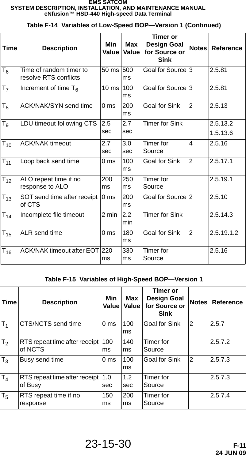
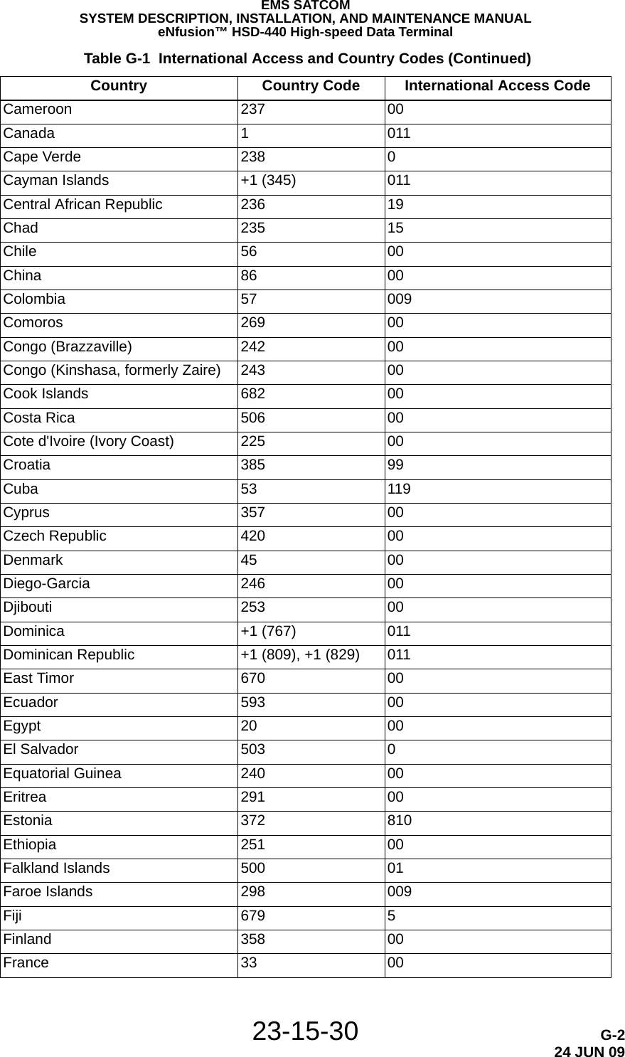
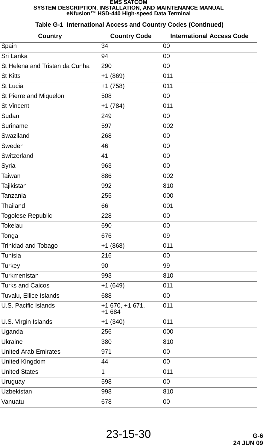
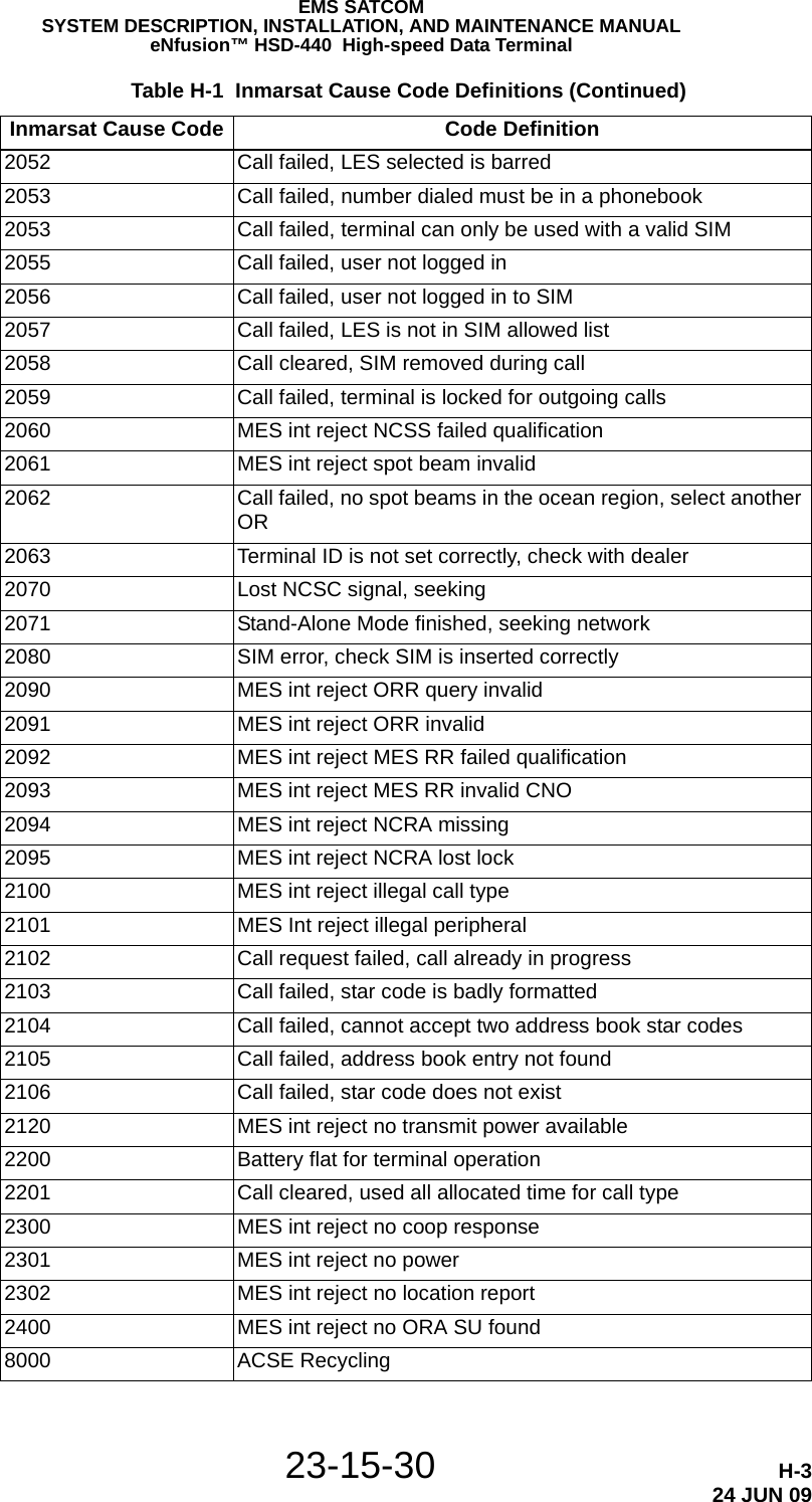
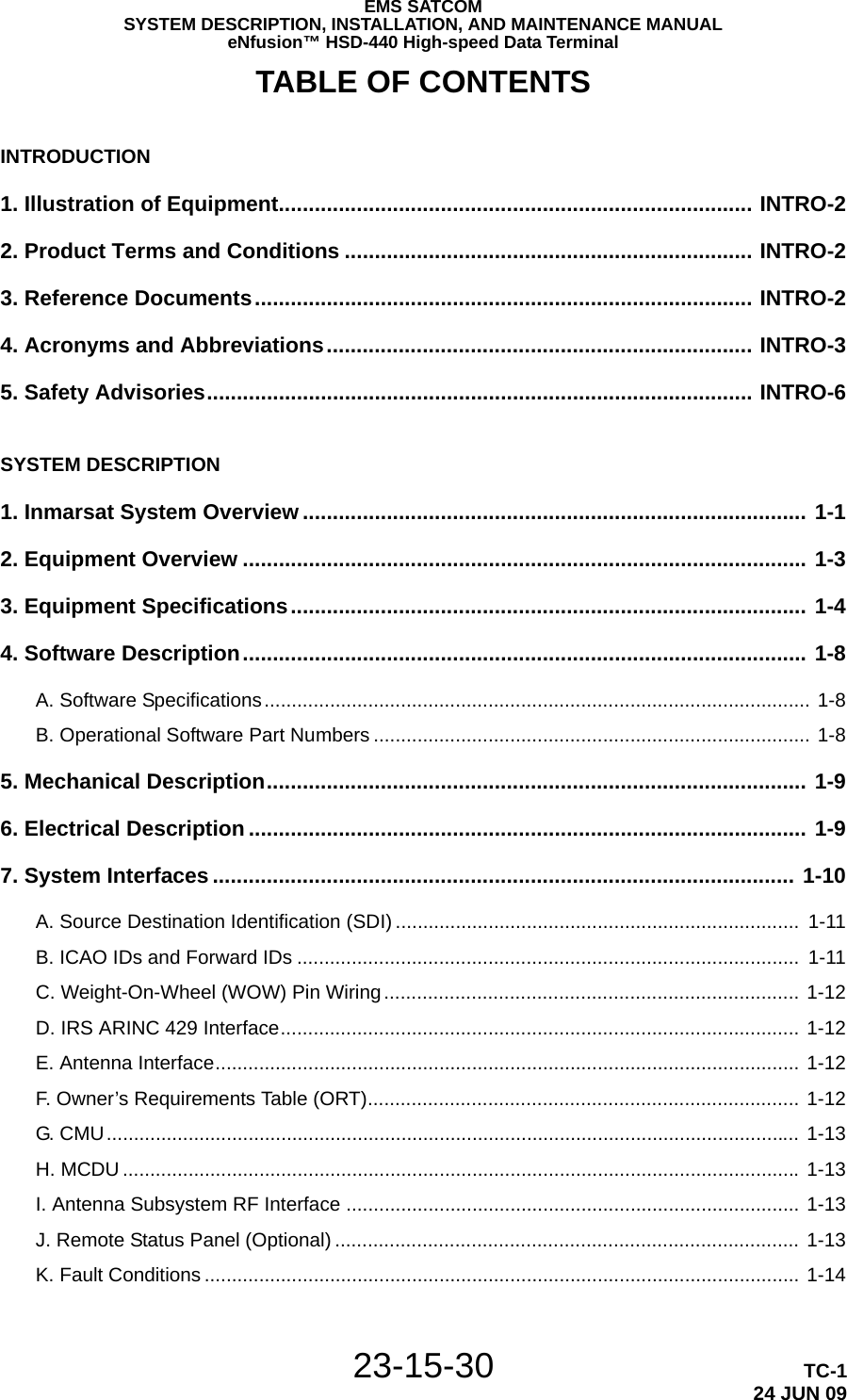
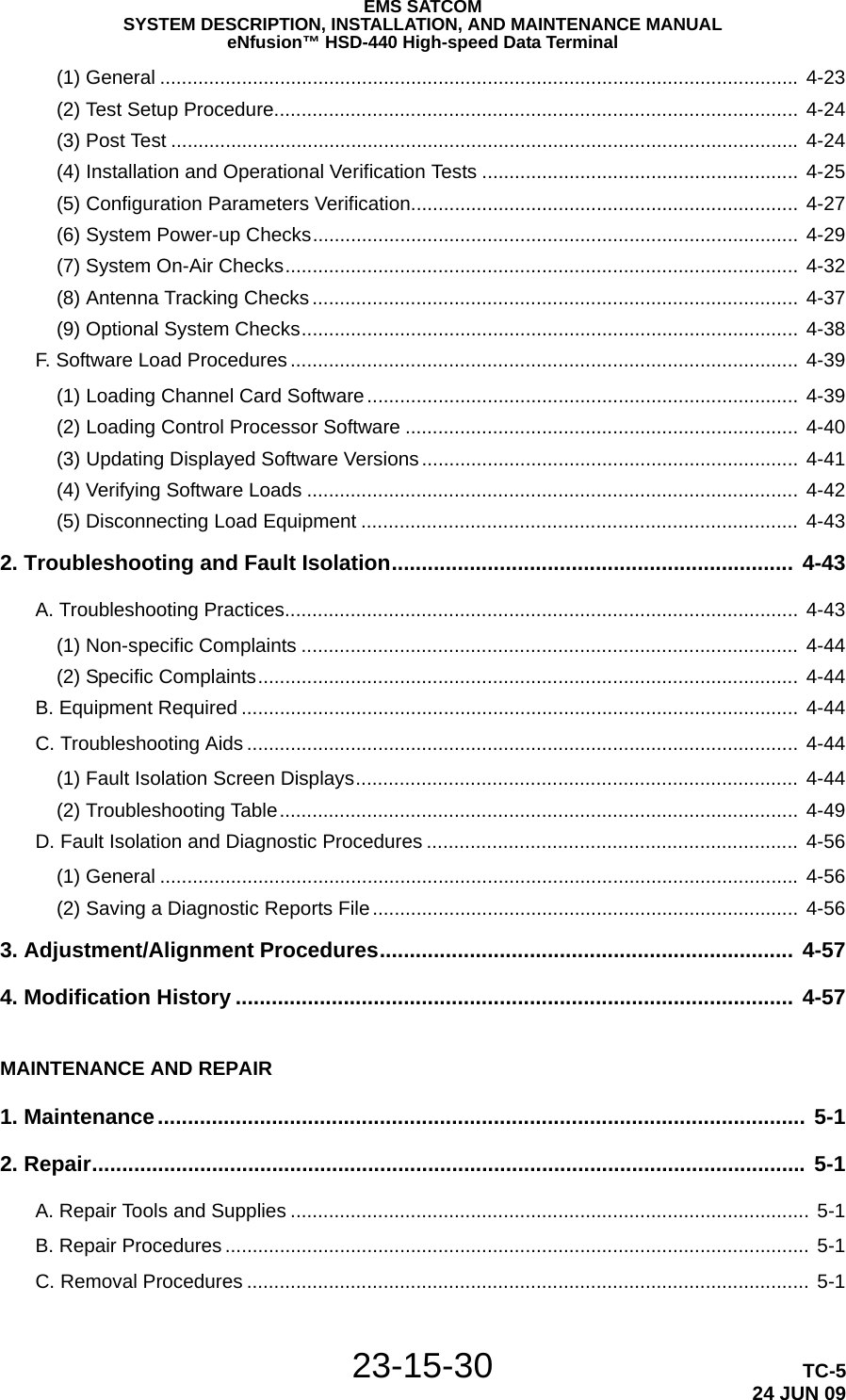
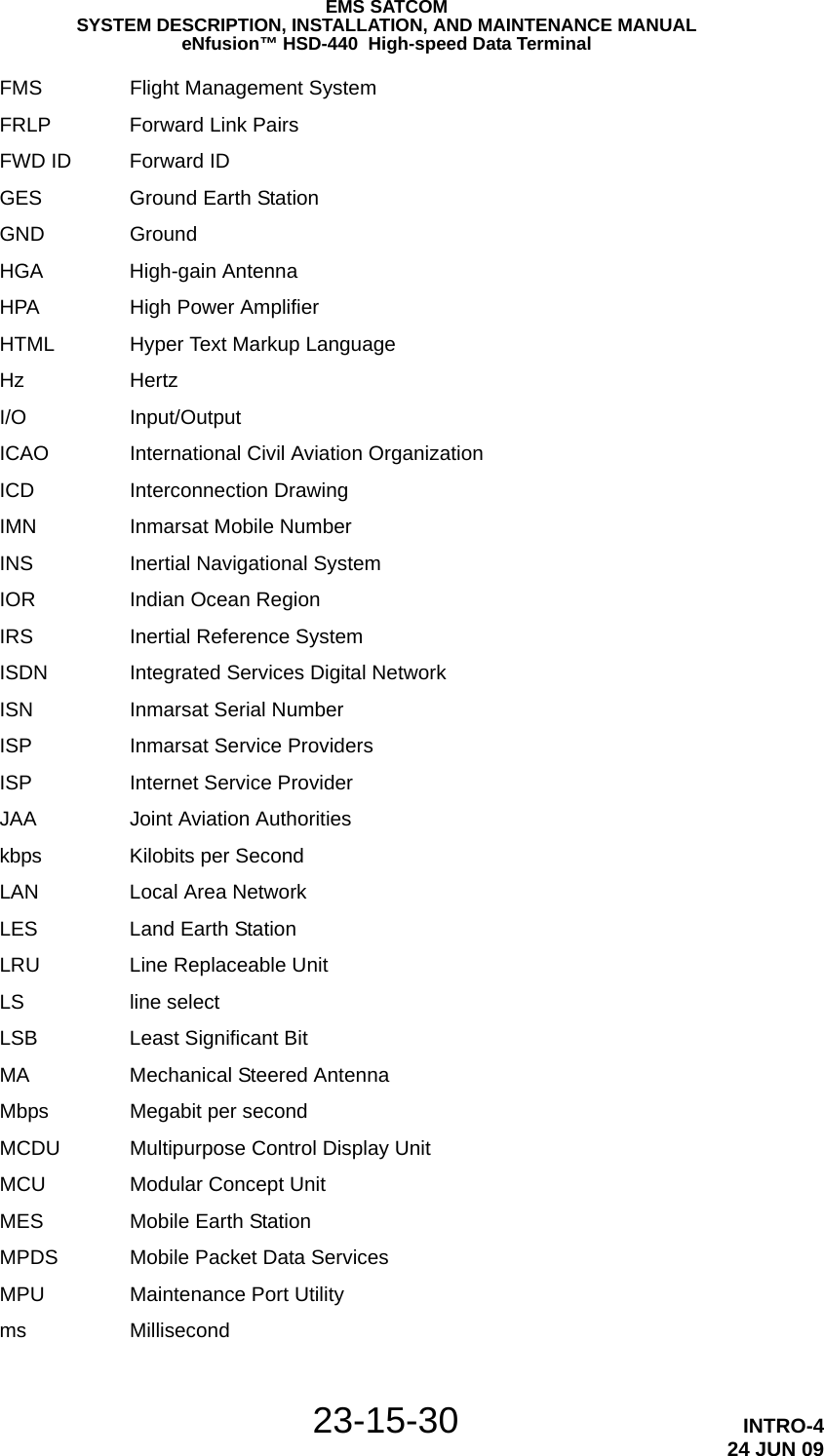
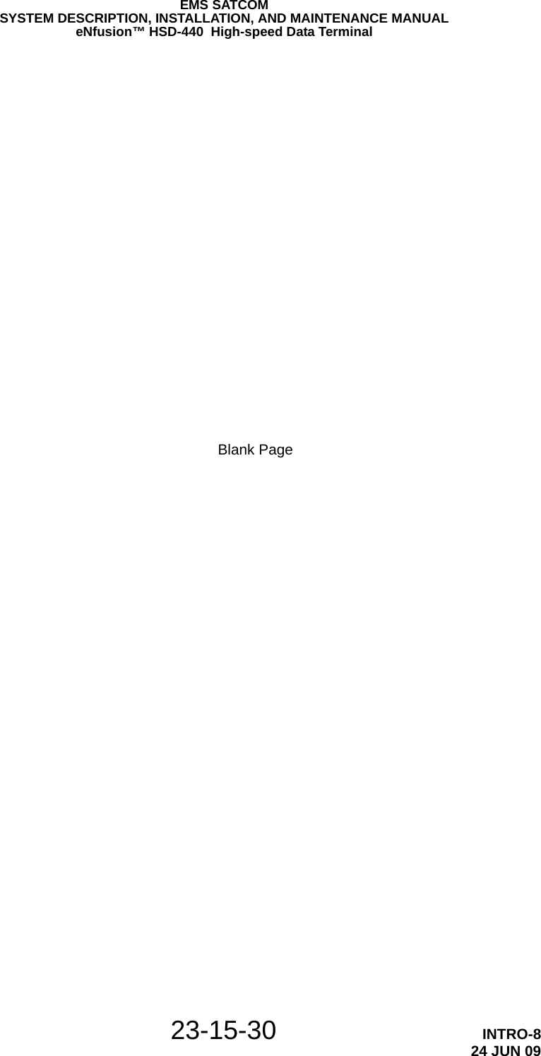
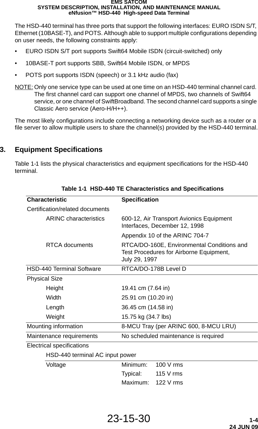
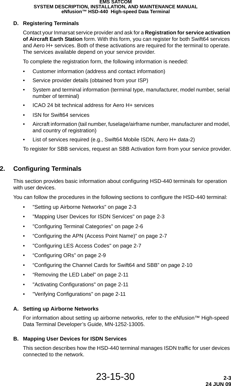
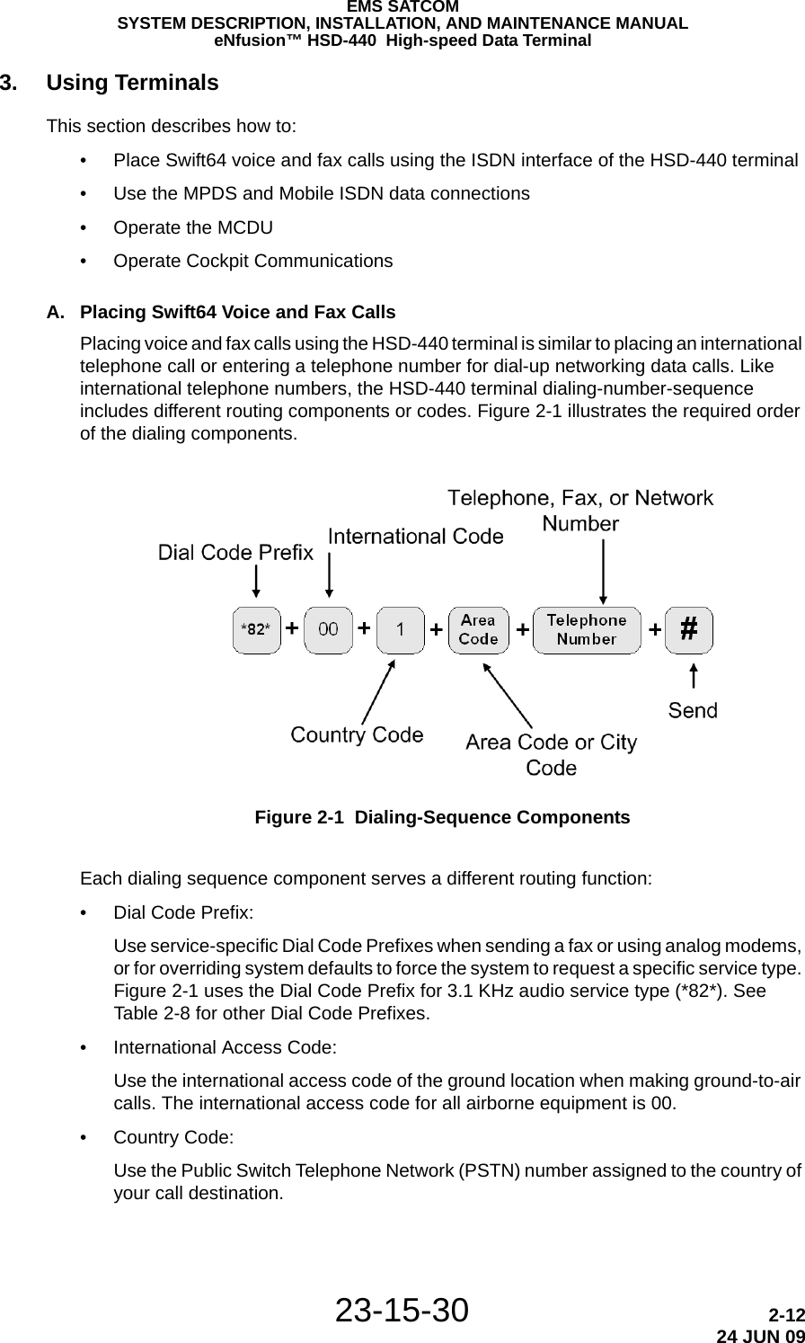
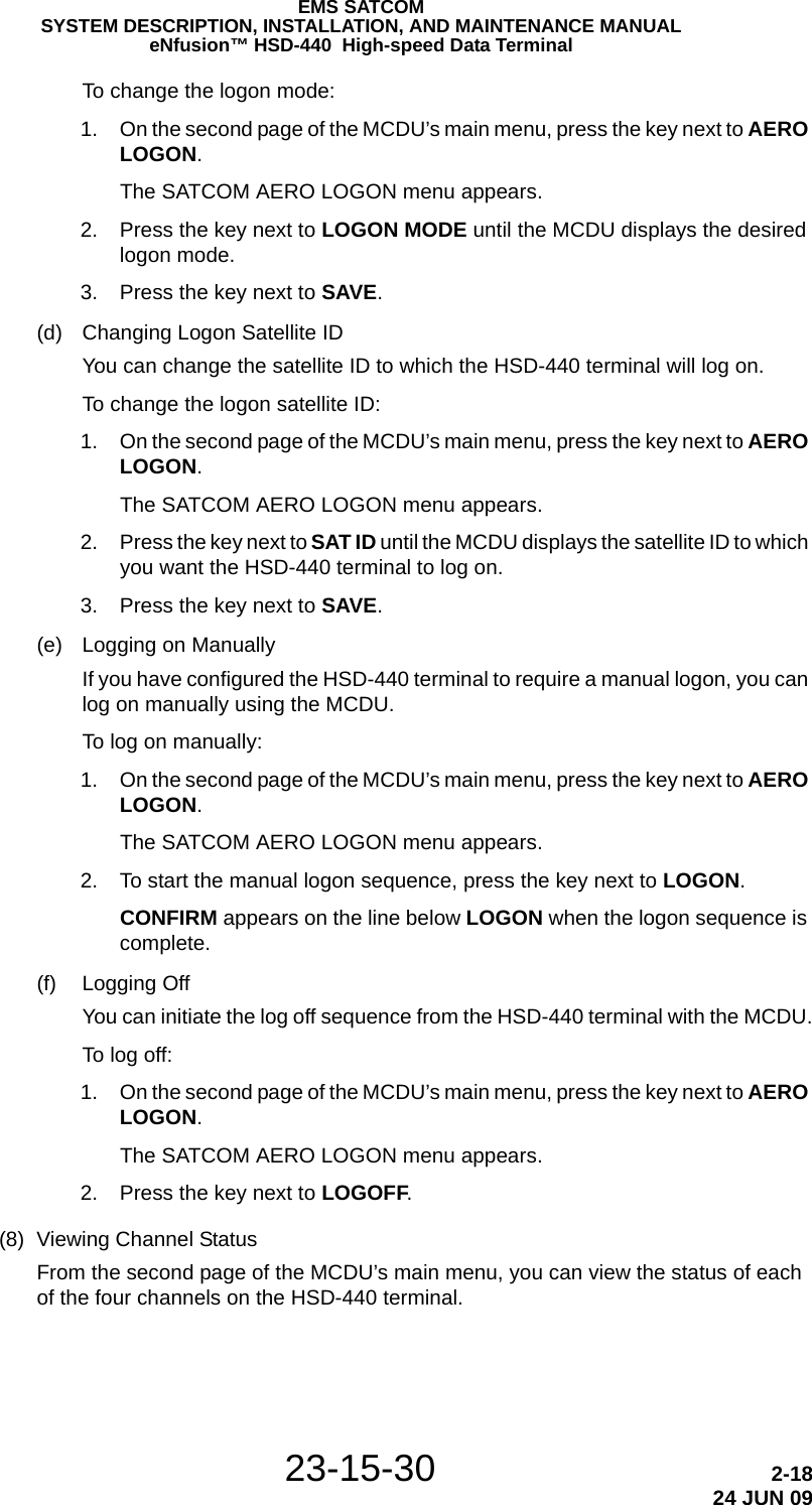
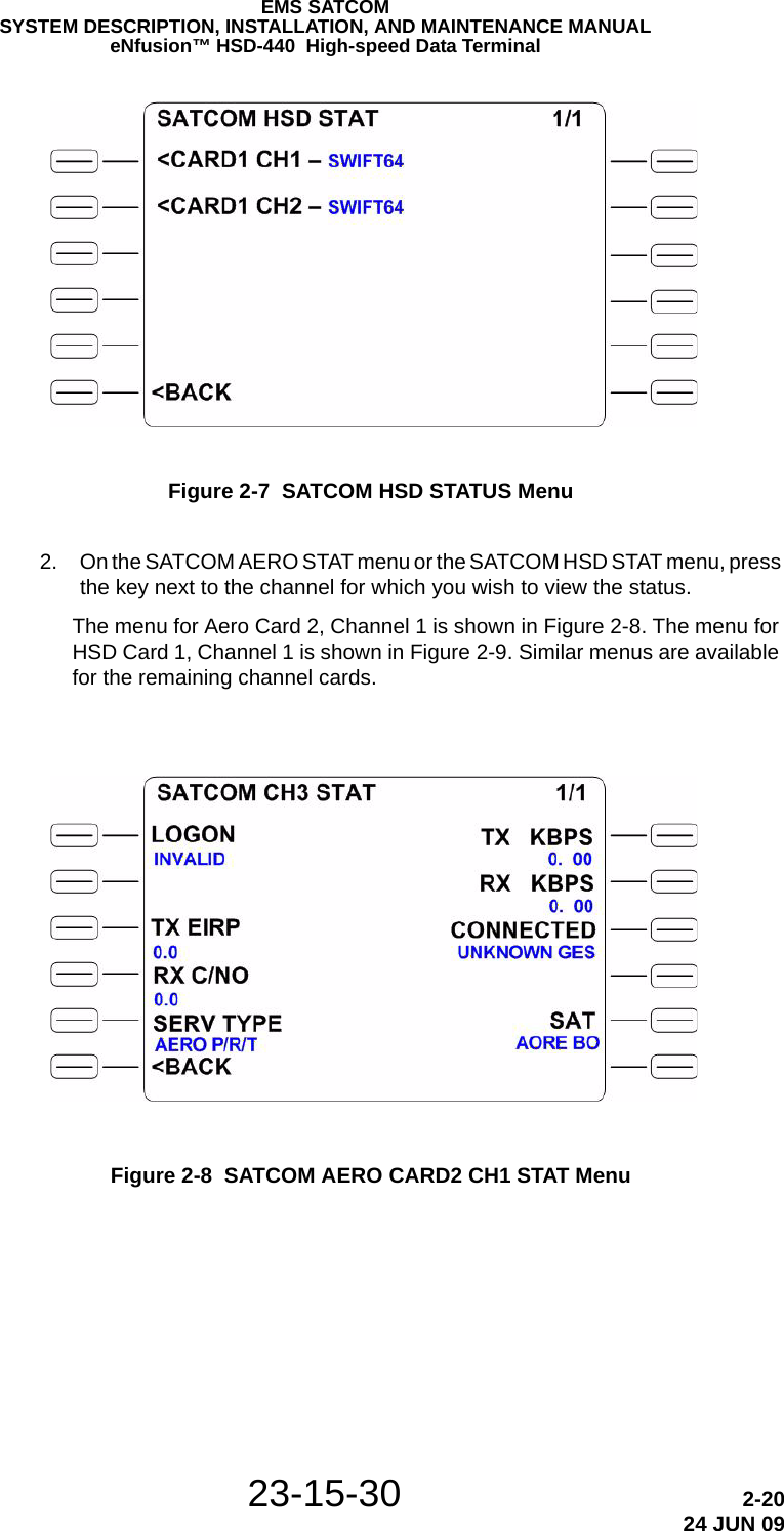
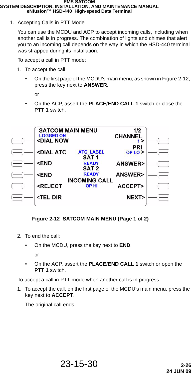
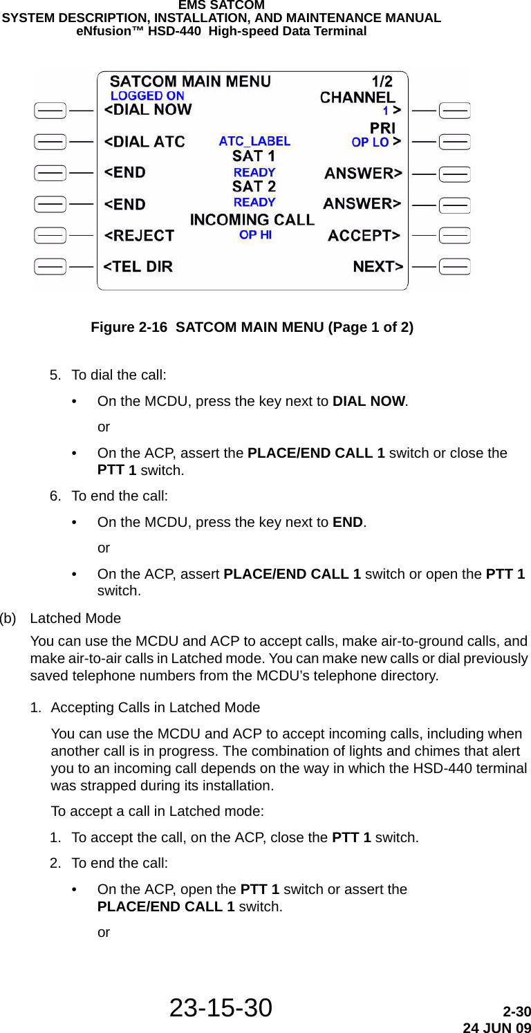
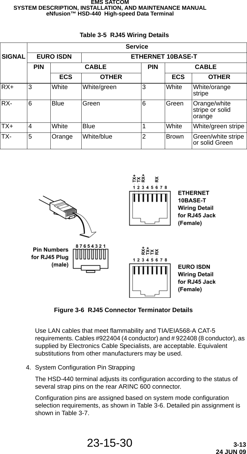
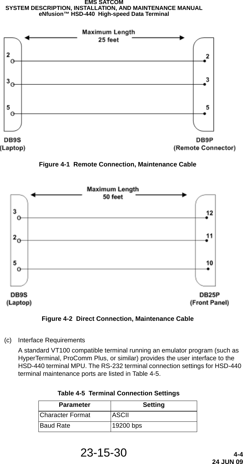
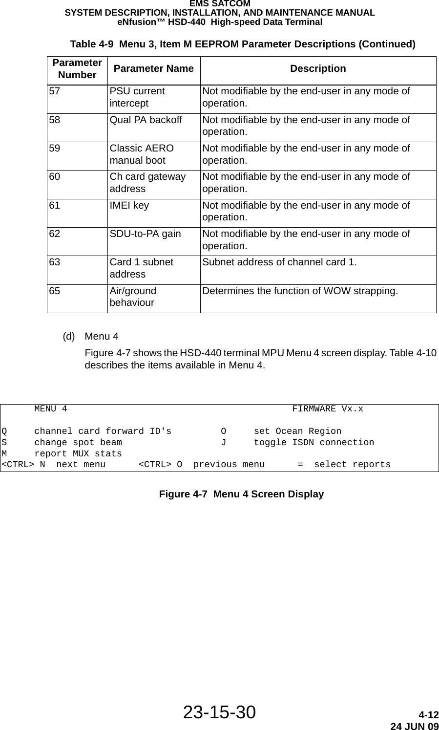
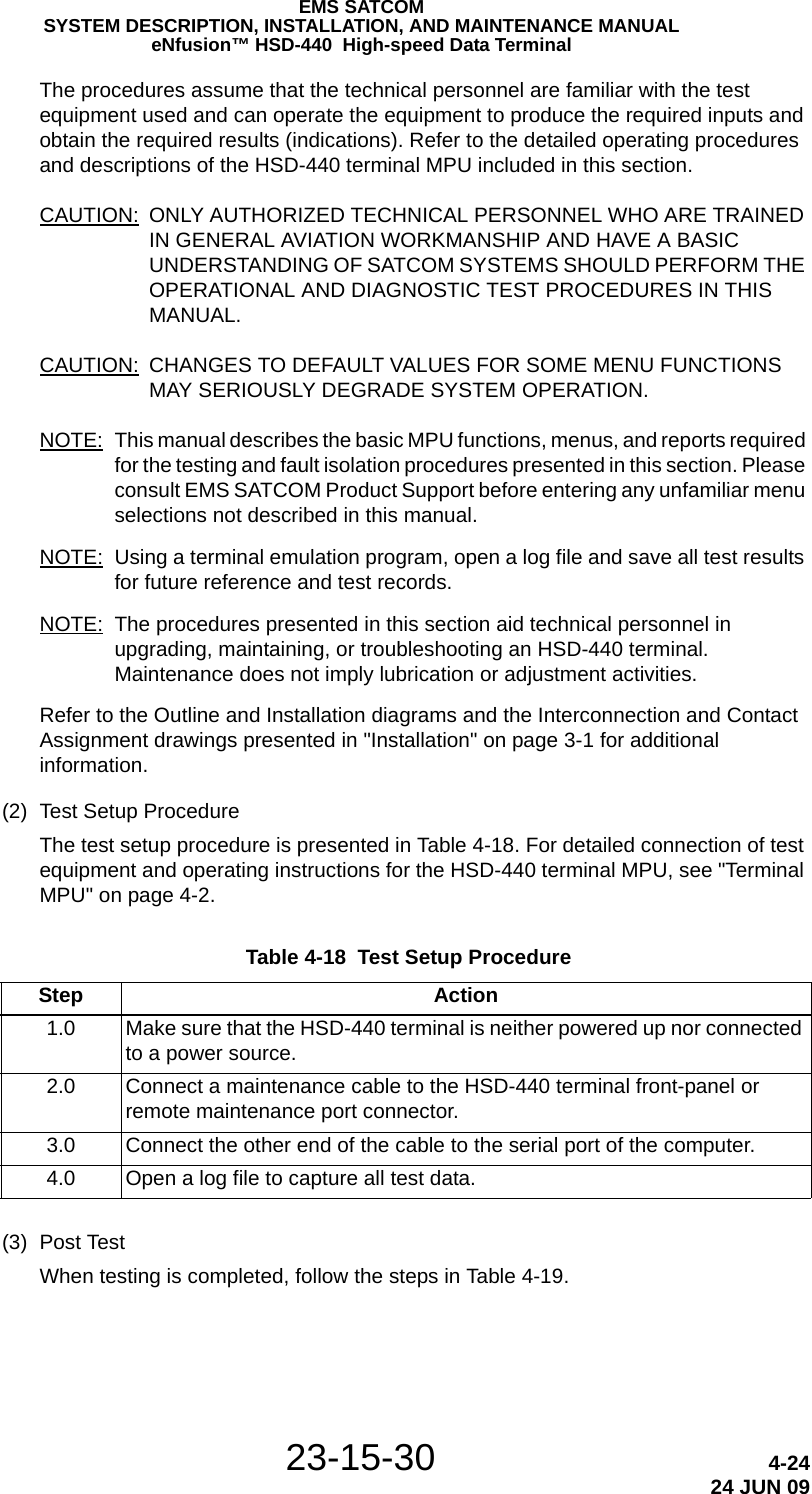
![EMS SATCOMSYSTEM DESCRIPTION, INSTALLATION, AND MAINTENANCE MANUALeNfusion™ HSD-440 High-speed Data Terminal23-15-30 4-3524 JUN 09Figure 4-21 Logon Initialization Display Example17:06:35 #2 DEF456 E5 start 400110 14.00 dBW CT SP ocean region registration 41.5 C 0 dB Hz17:06:35 #1 ABC123 E4 start 400110 14.00 dBW CT SP ocean region registration 41.5 C 0 dB HzCARD #2 LOGGING TEXT [34] 1004 DspMsg: P-status at t = 210 (fr = 1, sf = 1, uw 1)CARD #2 LOGGING TEXT [34] 1005 DspMsg: P-ch SF lock at t = 21017:06:36 #2 DEF456 E5 start 400110 14.00 dBW CT SP ocean region registration 41.5 C 0 dB Hz17:06:36 #1 ABC123 E4 start 400110 14.00 dBW CT SP ocean region registration 41.5 C 0 dB Hz17:06:38 #1 ABC123 E4 start 400110 14.00 dBW CT SP ocean region registration 41.5 C 0 dB Hz17:06:38 #2 DEF456 E5 start 400110 14.00 dBW CT SP ocean region registration 41.5 C 0 dB HzCARD #2 LOGGING TEXT [02] 1031 ALO: Required Rd-channel EIRP x100 = 2040CARD #2 LOGGING TEXT [02] 1032 ALO: Required T-channel [0] EIRP x100 = 910CARD #2 LOGGING TEXT [02] 1033 ALO: Required T-channel [1] EIRP x100 = 2040CARD #2 LOGGING TEXT [02] 1034 ALO: Required T-channel [2] EIRP x100 = 910CARD #2 LOGGING TEXT [02] 1035 ALO: Requesting Rd/T-channel power for chnl 1: eirp_X100 = 2040, min_slot = 14024, max slot = 1442217:06:40 #3 60104507 E4 start 400110 20.40 dBW aero logon 40.0 C 49 dB HzCARD #2 LOGGING TEXT [02] 1036 ALO: State = Await Rd/T-Channel PowerCARD #2 LOGGING TEXT [02] 1037 ALO: Rd/T-channel power allocated: EIRP X100 requested = 2040, allocated = 2040CARD #2 LOGGING TEXT [02] 1038 ALO: Tuning Pd/Rd, Pd = 14434, synchronized = 1CARD #2 LOGGING TEXT [05] 1039 ALO: Tuning P-channel(0) to 14434, rate=10500, CommonTiming = 0CARD #2 LOGGING TEXT [05] 1040 ALO: Tuning R-channel(1) to 14422, rate=10500, eirp_X100=2040CARD #2 LOGGING TEXT [34] 1041 DspMsg: P-status at t = 215 (fr = 0, sf = 0, uw 0)CARD #2 LOGGING TEXT [34] 1042 DspMsg: P-ch acquisition initiated at t = 21517:06:40 #1 ABC123 E4 start 400110 14.00 dBW CT SP ocean region registration 41.5 C 0 dB Hz17:06:40 #2 DEF456 E5 start 400110 14.00 dBW CT SP ocean region registration 41.5 C 0 dB HzCARD #2 LOGGING TEXT [02] 1043 ALO: State = Await Log-On ACKoCARD #2 LOGGING TEXT [34] 1044 DspMsg: P-status at t = 215 (fr = 1, sf = 0, uw 1)CARD #2 LOGGING TEXT [34] 1045 DspMsg: P-ch sync acquired at t = 21517:06:42 #1 ABC123 E4 start 400110 14.00 dBW CT SP ocean region registration 41.5 C 0 dB Hz17:06:43 #2 DEF456 E5 start 400110 14.00 dBW CT SP ocean region registration 41.5 C 0 dB HzCARD #2 LOGGING TEXT [06] 1139 DEA: Msg: Log onCARD #2 LOGGING TEXT [02] 1143 ALO: State = Logged-OnCARD #2 LOGGING TEXT [02] 1144 ALO: Satellite handover candidate 1: sat ID = 0, pref = 5, long X100 = -5250CARD #2 LOGGING TEXT [02] 1145 ALO: Satellite handover candidate 2: sat ID = 3, pref = 5, long X100 = 6300CARD #2 LOGGING TEXT [02] 1146 ALO: Satellite handover candidate 3: sat ID = 4, pref = 0, long X100 = 14250CARD #2 LOGGING TEXT [02] 1147 ALO: Satellite handover candidate 4: sat ID = 1, pref = 5, long X100 = -1500CARD #2 LOGGING TEXT [02] 1148 ALO: Satellite handover candidate 5: sat ID = 2, pref = 5, long X100 = 17850CARD #2 LOGGING TEXT [02] 1149 ALO: Satellite handover evaluation table initialized with 5 satellite(s)CARD #2 LOGGING TEXT [02] 1150 ALO: Satellite handover thresholds: bad EIRP = 5, bad antenna = 20, general = 20CARD #2 LOGGING TEXT [0b] 1163 LLUSER: Log-on AMIDUCARD #2 LOGGING TEXT [3f] 1164 LLUSER: Resetting link layer traffic statistics17:06:45 #1 ABC123 E4 start 400110 14.00 dBW CT SP ocean region registration 41.5 C 0 dB Hz17:06:45 #2 DEF456 E5 start 400110 14.00 dBW CT SP ocean region registration 41.5 C 0 dB HzCARD #2 LOGGING TEXT [34] 1275 DspMsg: P-status at t = 220 (fr = 1, sf = 1, uw 1)CARD #2 LOGGING TEXT [34] 1276 DspMsg: P-ch SF lock at t = 22017:06:49 #1 ABC123 E4 stop 8306 ACSE failed retry ORR 41.5 C 51 dB Hz17:06:49 #2 DEF456 E5 stop 8306 ACSE failed retry ORR 41.5 C 51 dB Hz17:06:52 #1 ABC123 E4 start 400110 14.00 dBW CT SP ocean region registration 41.5 C 51 dB Hz17:06:53 #2 DEF456 E5 start 400110 14.00 dBW CT SP ocean region registration 41.5 C 52 dB Hz17:06:56 #1 ABC123 E4 stop 8301 ACSE successful ORR 41.5 C 52 dB Hz17:06:58 #2 DEF456 E5 stop 8306 ACSE failed retry ORR 41.5 C 52 dB Hz17:07:01 #2 DEF456 E5 start 400110 14.00 dBW CT SP ocean region registration 41.5 C 52 dB Hz17:07:05 #2 DEF456 E5 stop 8301 ACSE successful ORR 41.5 C 52 dB HzCARD #2 LOGGING TEXT [02] 4350 ALO: Evaluating satellite handover for AES lat X100 = 4500, long X100 = -7500CARD #2 LOGGING TEXT [02] 4351 ALO: Current satellite = 1 has preference = 5, longitude delta X100 = 6000, elevation angle = 12.20 degreesCARD #2 LOGGING TEXT [02] 4352 ALO: Other candidate satellite = 0 has preference = 5, longitude delta X100 = 2250, elevation angle = 33.55 degreesCARD #2 LOGGING TEXT [02] 4353 ALO: Best satellite = 0 (not current), based on longitude deltaCARD #2 LOGGING TEXT [02] 4354 ALO: Satellite handover countdown = 19 minute(s)CARD #2 LOGGING TEXT [02] 4355 ALO: Evaluating spot beam handover for AES lat X100 = 4500, long X100 = -7500CARD #2 LOGGING TEXT [02] 4356 ALO: AES is still in beam 4CARD #2 LOGGING TEXT [02] 7537 ALO: Evaluating satellite handover for AES lat X100 = 4500, long X100 = -7500CARD #2 LOGGING TEXT [02] 7538 ALO: Current satellite = 1 has preference = 5, longitude delta X100 = 6000, elevation angle = 12.20 degreesCARD #2 LOGGING TEXT [02] 7539 ALO: Other candidate satellite = 0 has preference = 5, longitude delta X100 = 2250, elevation angle = 33.55 degreesCARD #2 LOGGING TEXT [02] 7540 ALO: Best satellite = 0 (not current), based on longitude deltaCARD #2 LOGGING TEXT [02] 7541 ALO: Satellite handover countdown = 18 minute(s)CARD #2 LOGGING TEXT [02] 7542 ALO: Evaluating spot beam handover for AES lat X100 = 4500, long X100 = -7500CARD #2 LOGGING TEXT [02] 7543 ALO: AES is still in beam 4](https://usermanual.wiki/EMS-Technologies-Canada/HSD-440/User-Guide-1257851-Page-155.png)
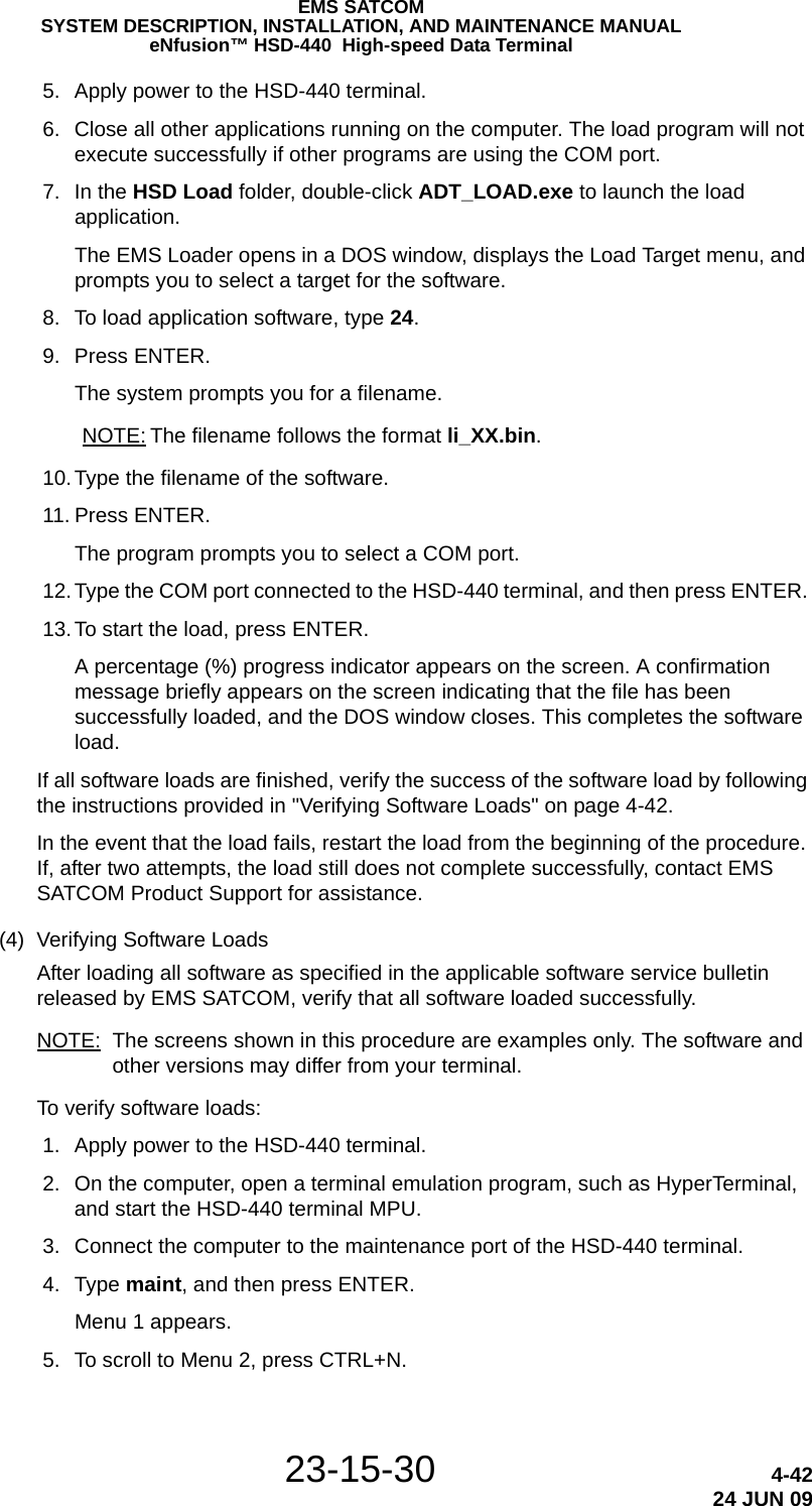

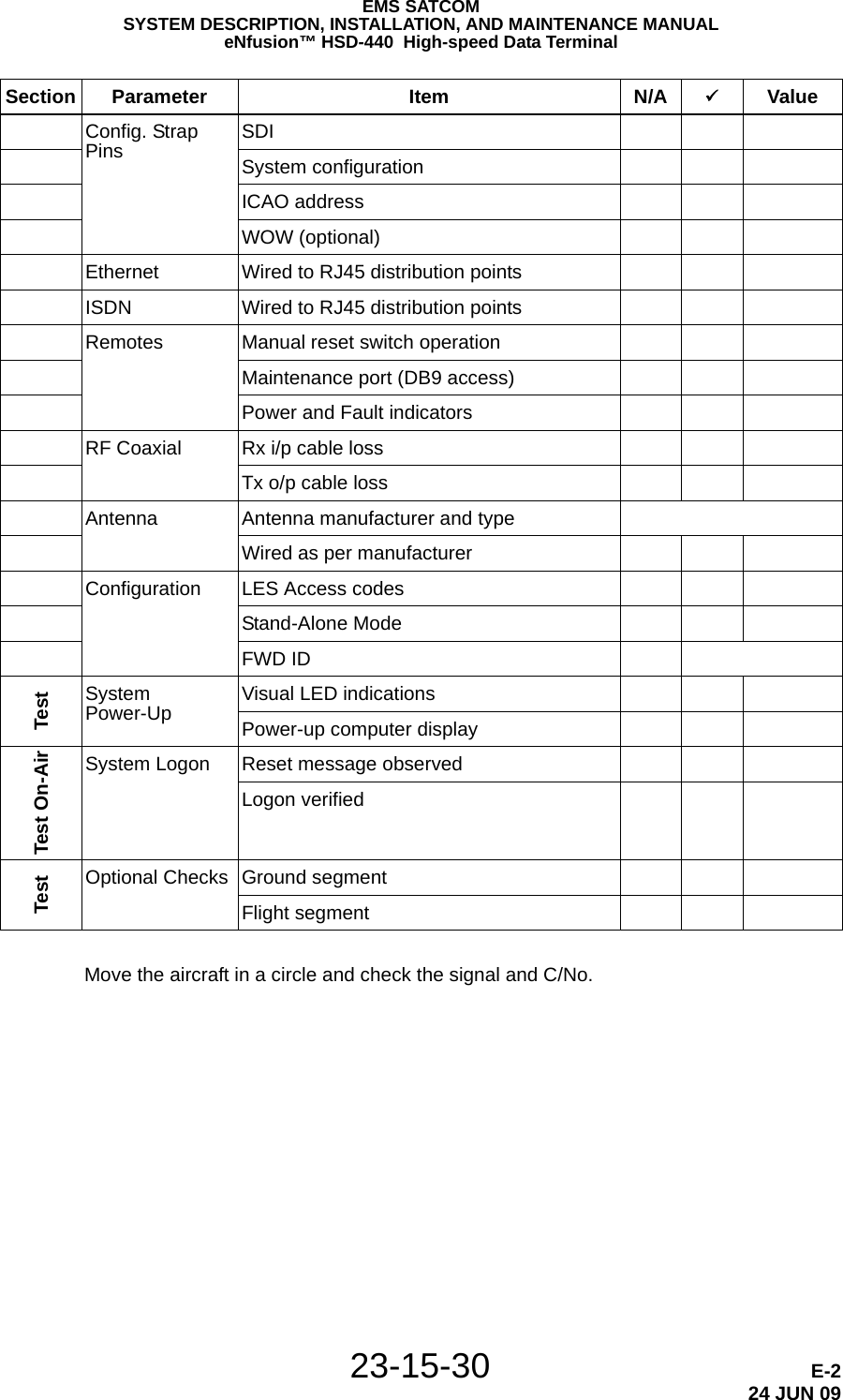
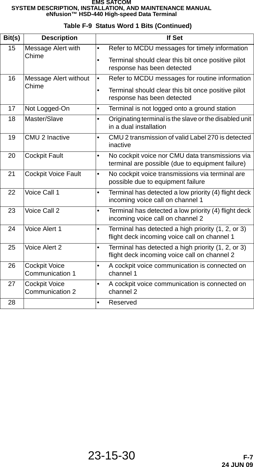
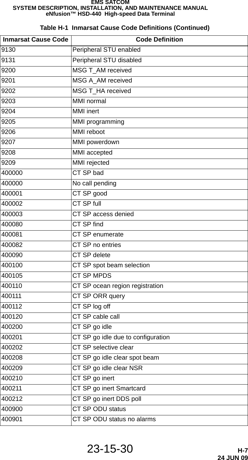
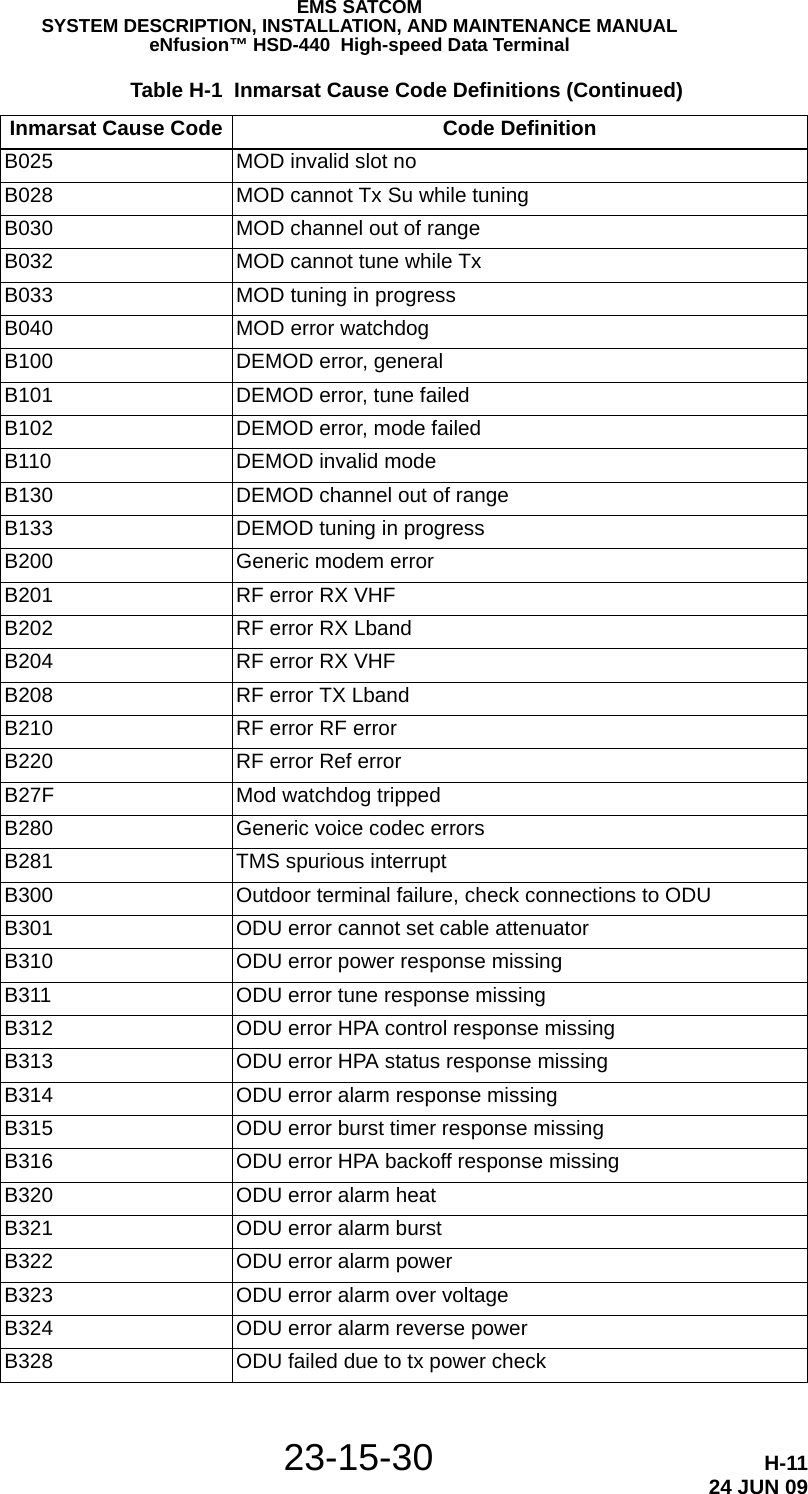
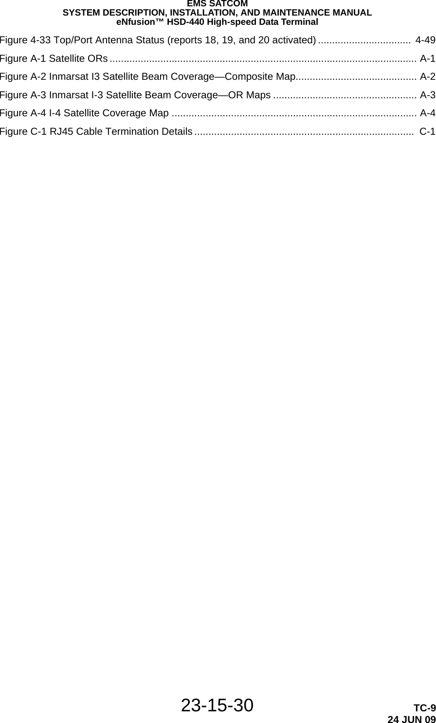
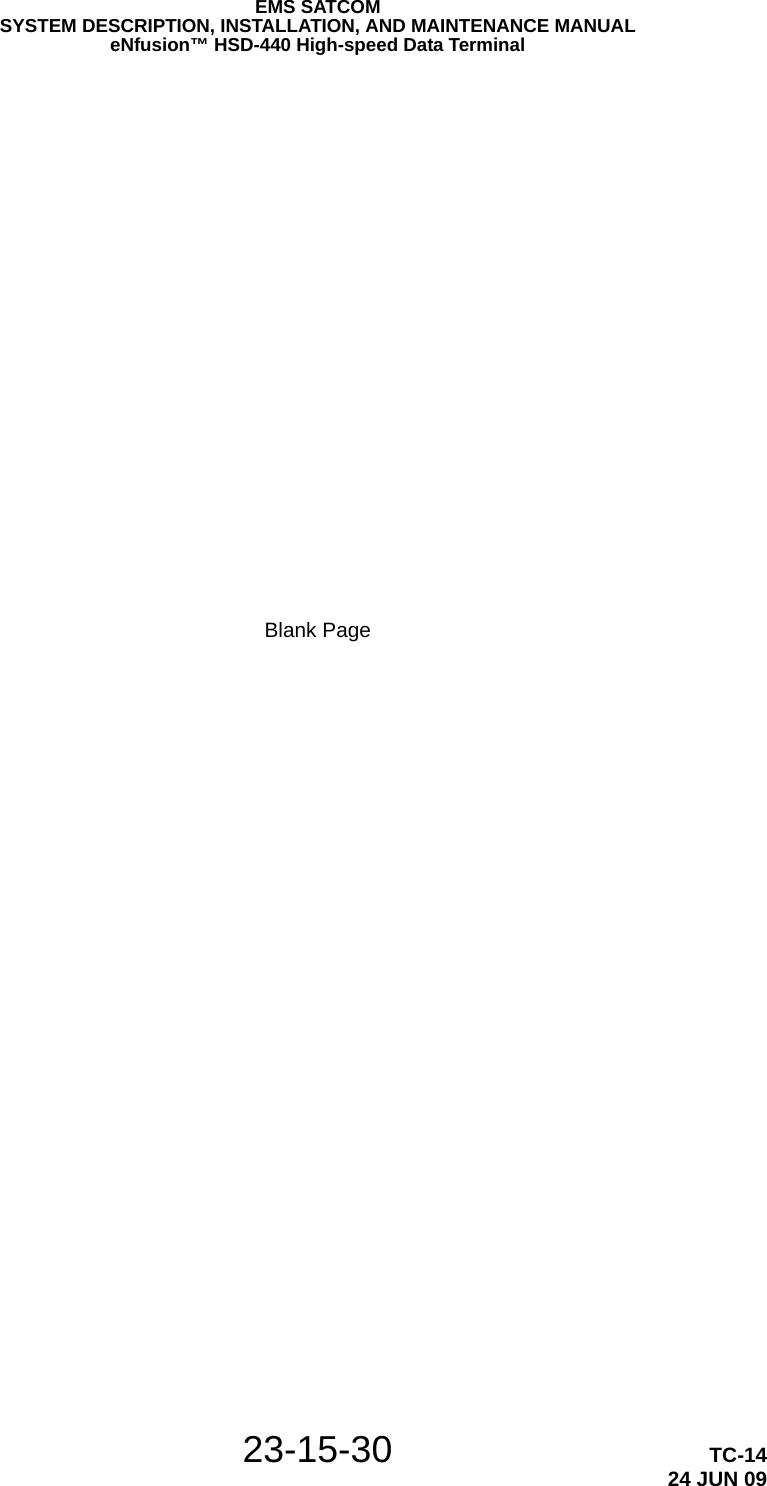
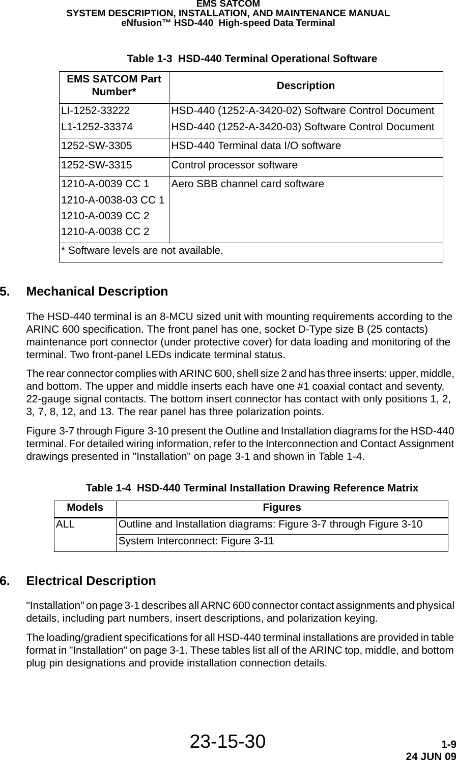
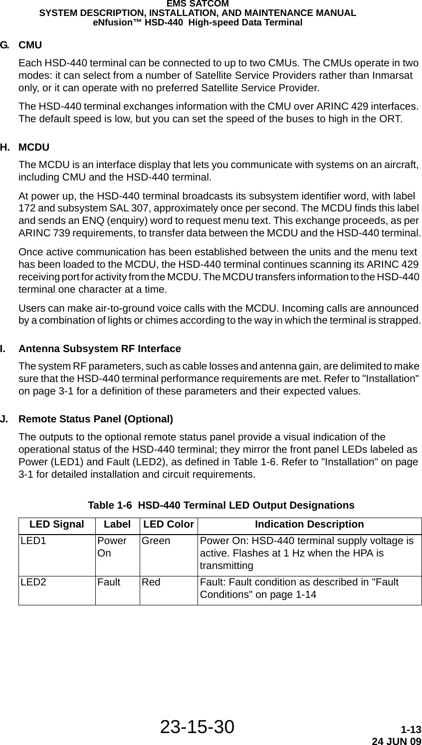
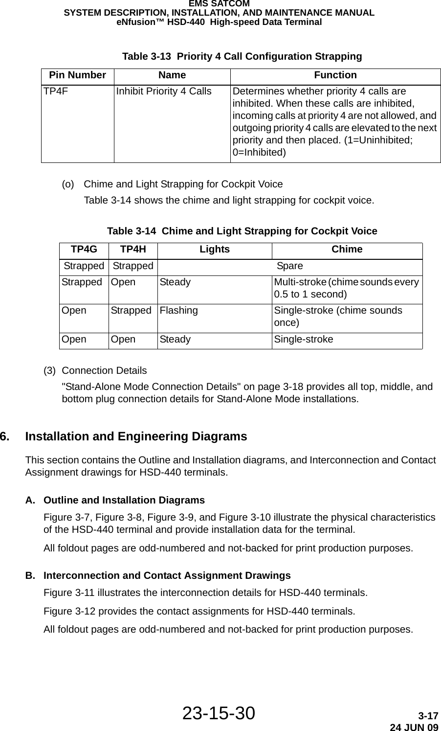
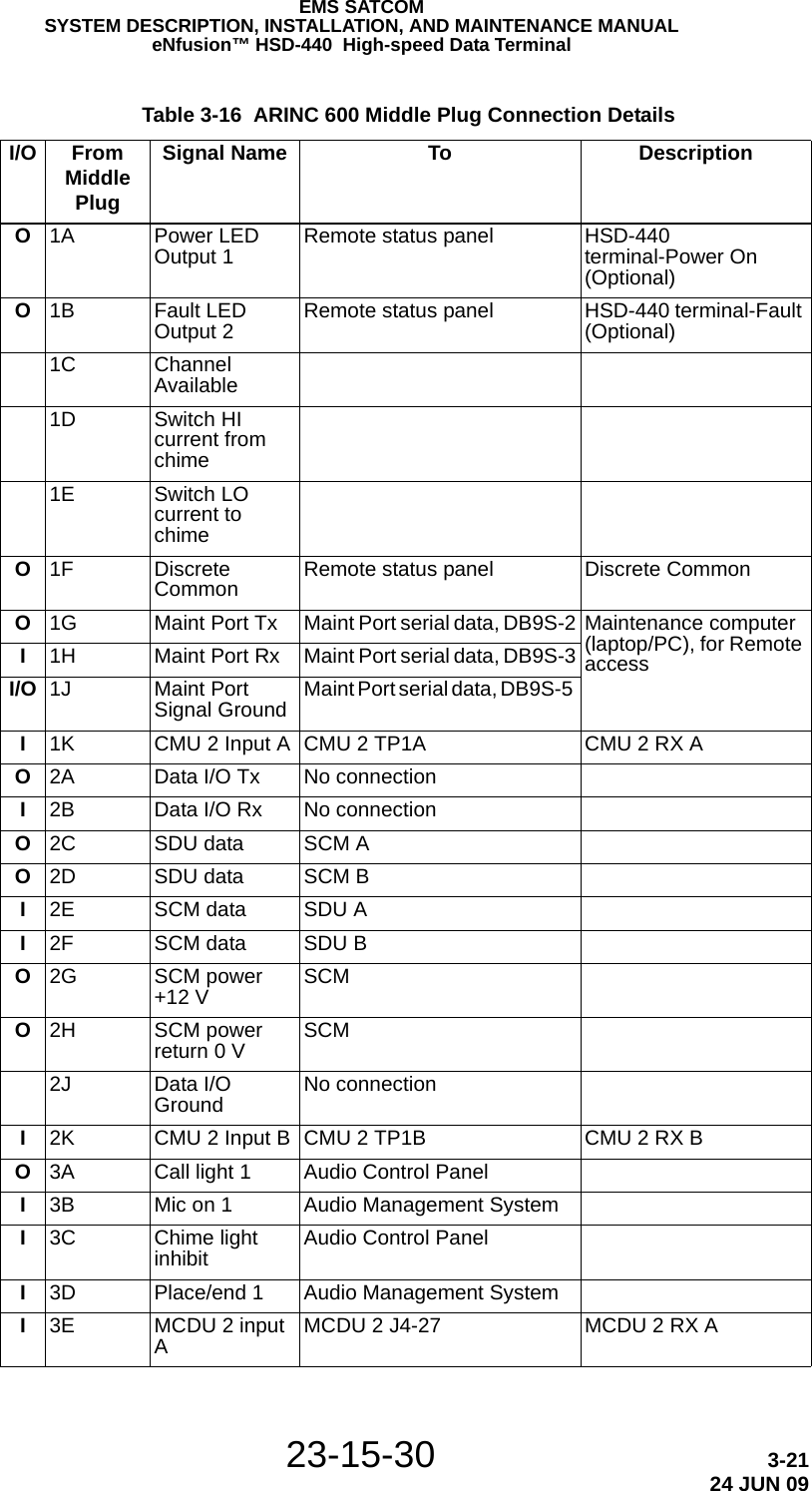
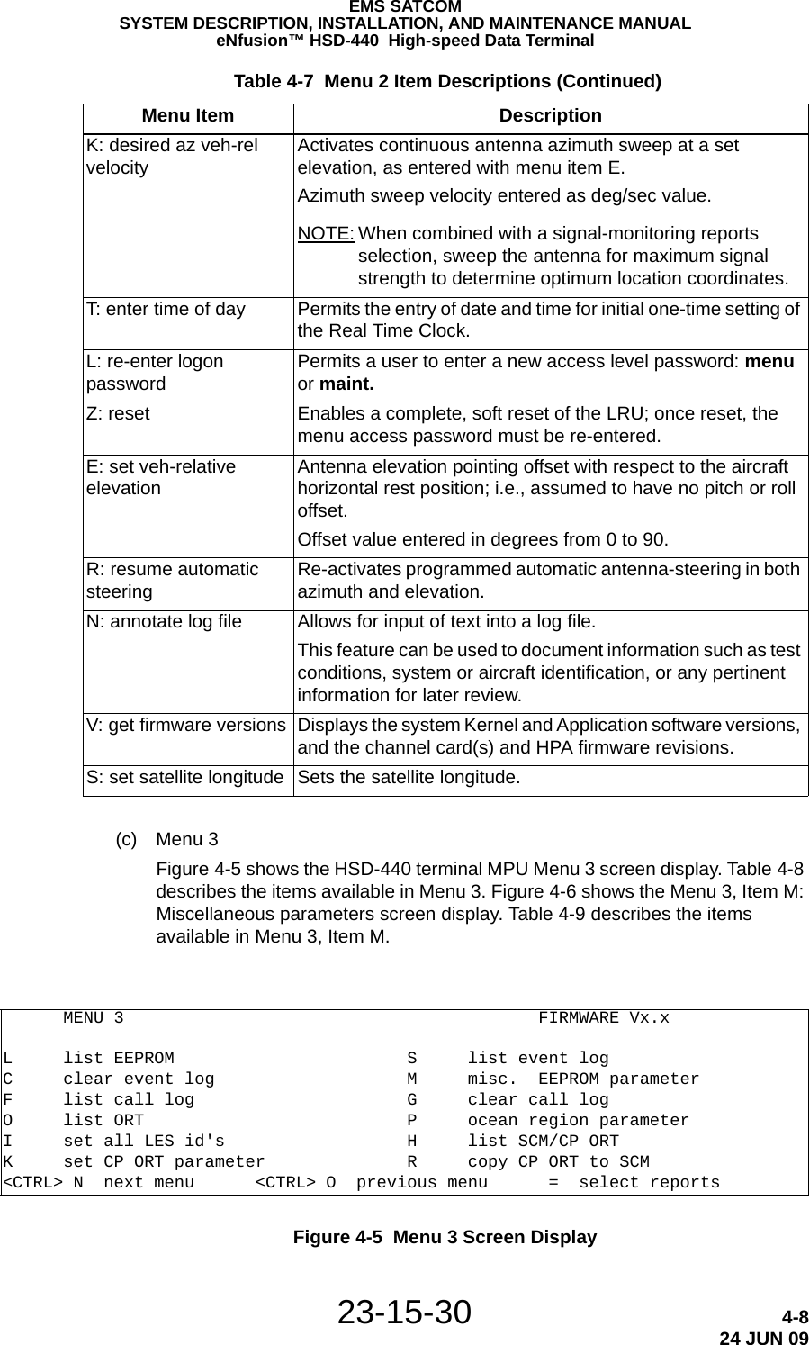
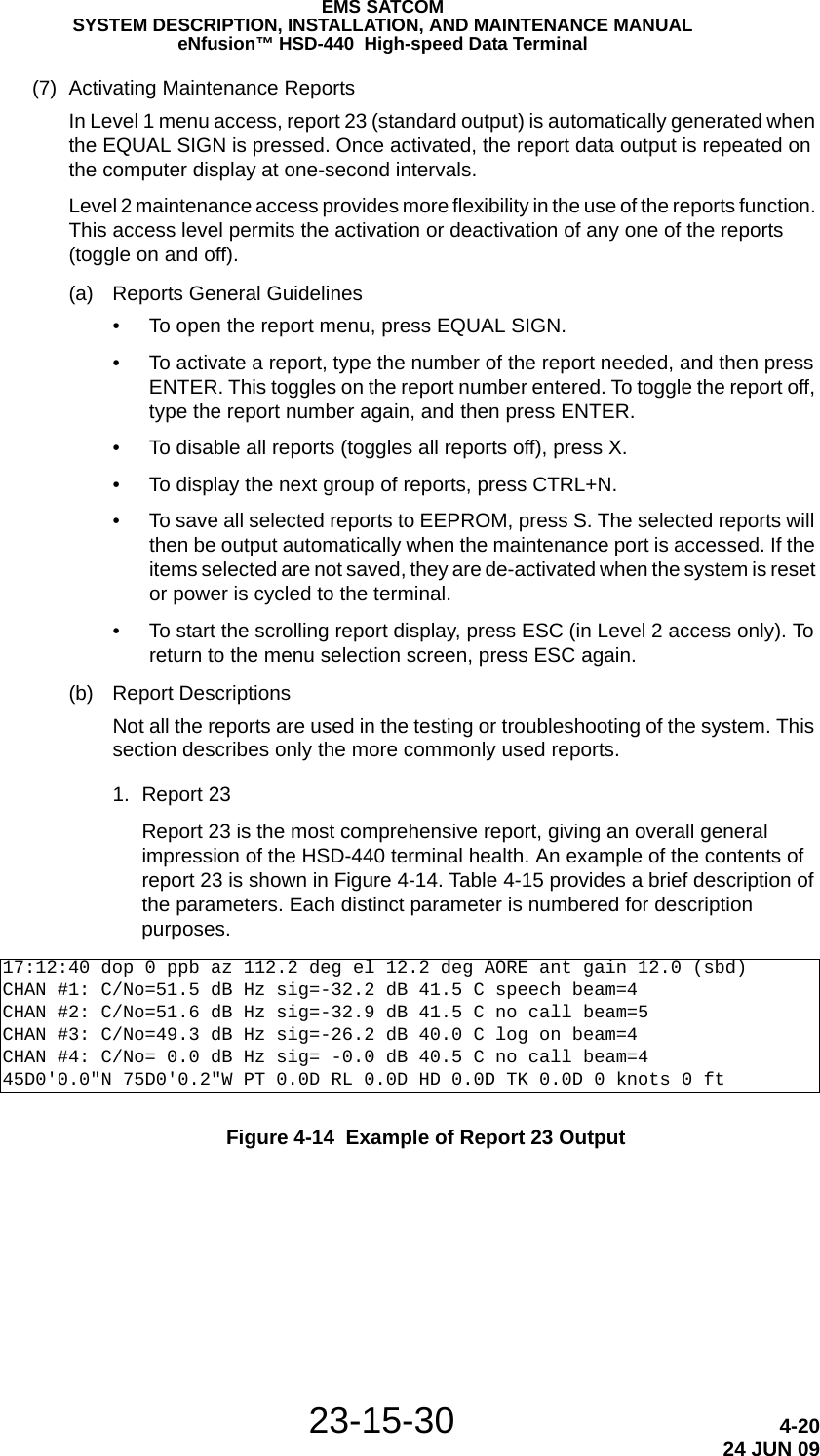
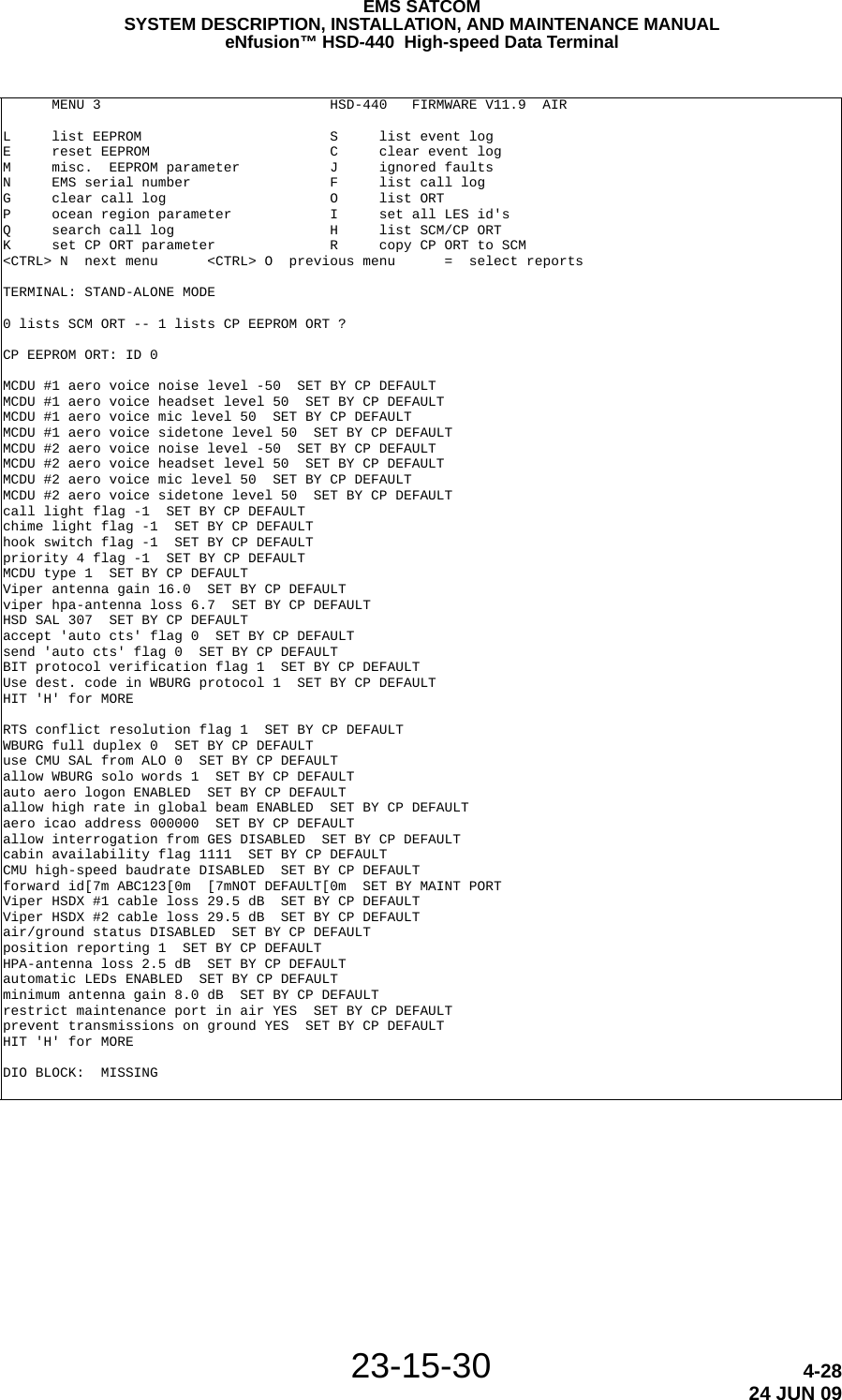
![23-15-30 5-424 JUN 09EMS SATCOMSYSTEM DESCRIPTION, INSTALLATION, AND MAINTENANCE MANUALeNfusion™ HSD-440 High-speed Data Terminalminimum equipment list (MEL)]. • HSD-440 terminals are not field-repairable. All terminals must be returned to the EMS SATCOM factory or authorized repair centers for repair.• Repaired terminals must be re-installed on the aircraft in accordance with the instructions provided in this manual. The operation of all repaired terminals must be verified using the operational verification tests and procedures provided in this manual before being approved for return to service. All special tools required to test the terminal for approval for return to service are listed and described in "Test and Fault Isolation" on page 4-1. Approval for return to service must be entered in the logbook as required by section 43.9 of the FAR.• The following scheduled maintenance tasks must be added to the aircraft operator's appropriate aircraft maintenance program:• Recommended periodic scheduled servicing tasks: None required.• Recommended periodic inspections: None required.• Recommended periodic scheduled preventative maintenance tests (tests to determine system condition and/or latent failures): None required.](https://usermanual.wiki/EMS-Technologies-Canada/HSD-440/User-Guide-1257851-Page-182.png)