EMS Technologies Canada HSD-X eNfusion HSD-X Aeronautical Satcom Terminal User Manual MN 1110 10113
EMS Technologies Canada, Ltd. eNfusion HSD-X Aeronautical Satcom Terminal MN 1110 10113
HSD-X User Manual

EMS SATCOM
400 Maple Grove Road
Ottawa, Ontario K2V 1B8
CANADA
eNfusion™ HSD-128 High-speed Data Terminal
System Description, Installation, and Maintenance Manual
MN-1110-10113
Revision E
18 September 2007
This manual supercedes MN-1110-10023 and MN-1110-10057 and provides
documentation for the equipment listed below.
Model PN
eNfusion™ HSD-128 High-speed Data
Terminal
1110-A-0001
1110-A-0060
1110-A-0070
1110-A-0080
1110-A-0150
1110-A-0160

PROPRIETARY STATEMENT
This document contains information which is proprietary and confidential to SATCOM
(EMS Technologies Canada, Ltd.). Neither this document nor the information contained within may
be used for any purpose other than the purpose for which it was prepared. Neither this document
nor the information contained within may be disclosed or copied without the prior written permission
of EMS SATCOM. © 2006 EMS Technologies Canada, Ltd. All Rights Reserved.
eNfusion™ HSD-128 High-speed Data Terminal SYSTEM DESCRIPTION, INSTALLATION, AND
MAINTENANCE MANUAL
Document Number: MN-1110-10113, Revision E
Copyright © 2006, 2007 EMS SATCOM (EMS Technologies Canada, Ltd.) All rights reserved. Cabin
Network Xcelerator® and CNX® are registered trademarks of EMS Technologies, Ltd. Windows is
a registered trademark of Microsoft Corporation in the United States and other countries. Other
product, brand, service, and company names herein are the trademarks of their respective owners.
The AMBE® voice compression technology embodied in this product is protected by intellectual
property rights including patent rights, copyrights and trade secrets of Digital Voice Systems, Inc.
This voice compression Technology is licensed solely for use within an Inmarsat satellite
communications system.
Our products are under continuous research and development. Any information may therefore be
changed without prior notice. EMS SATCOM reserves the right to make improvements or changes
in the product described in this manual at any time without notice. While reasonable efforts have
been made in the preparation of this document to assure its accuracy, EMS SATCOM assumes no
liability resulting from any errors or omissions in this document, or from the use of the information
contained herein.
Printed in Canada.
EMS SATCOM
400 Maple Grove Road, Ottawa, Ontario K2V 1B8, CANADA
EMS SATCOM Reception: 613-591-9064
EMS SATCOM Product Support: 888-300-7415 (routed to a Mobile after regular business
hours)
EMS SATCOM Product Support fax: 613-591-0797
EMS SATCOM E-mail Help: hsd.help@emssatcom.com
EMS SATCOM Web site: www.emssatcom.com
EMS SATCOM Sales and Marketing: 800-600-9759
Revision Table
Revision ECR Description
AN/A First release
B030758 Updated to include new installation modes
C040711
040673
050060
061189
Updated Service Bulletin Matrix
Added AMBE copyright statement
Updated middle plug connections on table and drawings
Updated terminology
D070552 Removed section cover pages
Updated frequency bands, service bulletins, and added
LED label section
E070111 Updated address and telephone numbers

CUSTOMER RESPONSE FORM
To help us improve the quality of our product documentation, EMS SATCOM would
appreciate your comments and suggestions on this publication. Please complete the
following customer survey and send to EMS SATCOM at:
EMS SATCOM
400 Maple Grove Road
Ottawa, ON K2V 1B8
E-mail: techdocs@emssatcom.com
Fax: EMS SATCOM Product Support at 613-591-3086
Publication information:
Customer information:
Comments and suggestions:
Publication number: MN-1110-10113
Publication title: eNfusion™ HSD-128 High-speed Data Terminal
System Description, Installation, and
Maintenance Manual
Latest issue date: 18 September 2007
Document revision: E
Name:
Company:
Tel:
Fax:
Email:
Date:
Comments:
Blank Page

Page SBL–1
25 May 2007
SYSTEM DESCRIPTION, INSTALLATION, AND MAINTENANCE MANUAL
eNfusion™ HSD-128 High-speed Data Terminal
SERVICE BULLETIN LIST
Service
Bulletin
Number
Subject Manual Rev.
Number
Manual Rev.
Date
1110-SB-0001 Channel card software upgrade
(C30) to accommodate Inmarsat
system change
A 10-Feb-03
1110-SB-0002 Backplane modification to HPA
wiring harness and power supply
circuits of the control processor
card
A 10-Feb-03
1110-SB-0003 Upgrade to HSD HPA software to
improve power management by
the HSD to the SAT-906 SDU
A 08-Apr-03
1110-SB-0004 Upgrade hardware to include an
Data I/O Type 2 Card to support
the Ethernet (10BASE-T)
interface for data input and output
A 06-Aug-03
1110-SB-0005 Upgrade the hardware for
Combined Mode operation
B 06-Aug-03
1110-SB-0006 Channel Card Software MPDS
upgrade
A 05-Nov-03
1110-SB-0007 Software upgrade for
Multi-Channel operation
A 20-Nov-03
1110-SB-0008 Not applicable N/A N/A
1110-SB-0009 Not applicable N/A N/A
1110-SB-0010 Hardware upgrade for dual
channel
A 05-Aug-03
1110-SB-0011 HSD Software Upgrade B 19-Nov-03
1110-SB-0012 HSD Software Enhancement A 19-Nov-03
1110-SB-0013 Addition of Software Identification
Label
A 09-Dec-03
1110-SB-0014 Data I/O Type 2 Software
Upgrade
A 12-Mar-04
1110-SB-0015 HSD Control Processor Software
Enhancement
B 15-Jun-04
1110-SB-0016 HSD Transceiver Upgrade to
HSD-400
C 13-Oct-06

Page SBL–2
25 May 2007
SYSTEM DESCRIPTION, INSTALLATION, AND MAINTENANCE MANUAL
eNfusion™ HSD-128 High-speed Data Terminal
1110-SB-0017 HSD Transceiver Control
Processor Software
Enhancement
A 24-Feb-05
1110-SB-0018 HSD Transceiver Channel Card
Hardware Modification
C 10-Aug-05
1110-SB-0020 HSD Transceiver HPA DC
Software Upgrade
A 31-May-05
1110-SB-0021 2-Channel Cooperative Mode
HSD Transceiver Control
Processor Software
Enhancement
A 01-Feb-06
1110-SB-0022 GPS Protection Software
Upgrade
B 03-Jan-07
1110-SB-0023 HSD Transceiver Motherboard
Hardware Replacement
A 25-Aug-06
1110-SB-0401 HSD-X Software Upgrade A 19-Nov-03
1110-SB-0402 Addition of Software Identification
Label
A09-Dec-03
Service
Bulletin
Number
Subject Manual Rev.
Number
Manual Rev.
Date

Page RR–1
18 September 2007
SYSTEM DESCRIPTION, INSTALLATION, AND MAINTENANCE MANUAL
eNfusion™ HSD-128 High-speed Data Terminal
RECORD OF REVISIONS
When revisions are received, insert revised pages, record the date, and initial.
Revision
Number
Issue
Date
Date
Inserted
Inserted
by
(initial)
Revision
Number
Issue
Date
Date
Inserted
Inserted
by
(initial)
Page RR–2
18 September 2007
SYSTEM DESCRIPTION, INSTALLATION, AND MAINTENANCE MANUAL
eNfusion™ HSD-128 High-speed Data Terminal
Blank Page

Page LEP–1
18 September 2007
SYSTEM DESCRIPTION, INSTALLATION, AND MAINTENANCE MANUAL
eNfusion™ HSD-128 High-speed Data Terminal
LIST OF EFFECTIVE PAGES
* An asterisk indicates pages changed, added, or deleted by the current revision.
F indicates a right foldout page with a blank back.
Section Page Date
Cover *ALL Nov. 3, 2006
Front Matter *ALL Nov. 3, 2006
Customer Comment Form *ALL Nov. 3, 2006
List of Effective Pages *ALL Nov. 3, 2006
Record of Revisions *ALL Nov. 3, 2006
Service Bulletin List *ALL Nov. 3, 2006
Table of Contents *ALL Nov. 3, 2006
Introduction *ALL Nov. 3, 2006
System Description *ALL Nov. 3, 2006
System Operation *ALL Nov. 3, 2006
Installation *ALL Nov. 3, 2006
Test and Fault Isolation *ALL Nov. 3, 2006
Maintenance and Repair *ALL Nov. 3, 2006
Appendix A *ALL Nov. 3, 2006
Appendix B *ALL Nov. 3, 2006
Appendix C *ALL Nov. 3, 2006
Appendix D *ALL Nov. 3, 2006
Appendix E *ALL Nov. 3, 2006
Appendix F *ALL Nov. 3, 2006
Service Bulletin List *ALL May 25, 2007
List of Effective Pages *ALL May 25, 2007
System Description *ALL May 25, 2007
System Operation *ALL May 25, 2007
Page LEP–2
18 September 2007
SYSTEM DESCRIPTION, INSTALLATION, AND MAINTENANCE MANUAL
eNfusion™ HSD-128 High-speed Data Terminal
Blank Page
SYSTEM DESCRIPTION, INSTALLATION, AND MAINTENANCE MANUAL
eNfusion™ HSD-128 High-speed Data Terminal
Page TC–1
18 September 2007
Table of Contents
INTRODUCTION
1. General .................................................................................................... TC-1
2. Abbreviations and Acronyms................................................................. TC-2
3. Advisories ................................................................................................ TC-4
4. Illustration of Equipment Covered......................................................... TC-5
SYSTEM DESCRIPTION
1. Purpose of Equipment .............................................................................. 1-1
2. Equipment Covered.................................................................................... 1-3
A. Hardware Description ......................................................................................... 1-3
B. Software Description .......................................................................................... 1-5
(1) Software Specifications ................................................................................. 1-5
(2) Operational Software Part Numbers.............................................................. 1-6
(3) Operational Mode Software Requirements.................................................... 1-6
(4) Software Version Description ........................................................................ 1-8
3. Equipment Description ............................................................................ 1-14
A. Applicable Documents...................................................................................... 1-14
B. Reference Documents...................................................................................... 1-14
C. Equipment Specifications ................................................................................. 1-14
D. Mechanical Description .................................................................................... 1-19
(1) HSD Transceiver ........................................................................................ 1-19
(2) HSD-X Transceiver...................................................................................... 1-19
E. Electrical Description........................................................................................ 1-20
(1) General ....................................................................................................... 1-20
(2) Pin and Connector Descriptions .................................................................. 1-21
F. System Interface Descriptions .......................................................................... 1-21
(1) HSD System Interfaces ............................................................................... 1-21
(2) HSD-X Multi-Channel System Interfaces .................................................... 1-24
G. User Interfaces ................................................................................................. 1-27
SYSTEM DESCRIPTION, INSTALLATION, AND MAINTENANCE MANUAL
eNfusion™ HSD-128 High-speed Data Terminal
Page TC–2
18 September 2007
(1) Stand-Alone Mode User Interfaces..............................................................1-28
(2) Collins Cooperative Mode User Interfaces ..................................................1-28
(3) Honeywell Combined Mode User Interfaces ............................................... 1-28
(4) Selective Mode User Interfaces................................................................... 1-28
(5) Multi-Channel Configurations ...................................................................... 1-28
(6) ISDN Circuit-Switched Data Interface ......................................................... 1-31
(7) RS-232 Interface ........................................................................................ 1-32
(8) Ethernet Data Interface ............................................................................... 1-33
(9) ISDN S/T Interface ...................................................................................... 1-33
(10) Maintenance Port Interface ....................................................................... 1-33
H. Initiated-Self-Test.............................................................................................. 1-34
I. Owner Requirements Table ............................................................................... 1-34
4. Inmarsat System Overview...................................................................... 1-35
A. General............................................................................................................. 1-35
B. Satellite Network Overview............................................................................... 1-35
5. HSD Modes and Configuration Descriptions......................................... 1-37
A. General............................................................................................................. 1-37
B. Overview........................................................................................................... 1-37
(1) Channel Card Configurations ...................................................................... 1-37
(2) Installation Modes and Configurations......................................................... 1-38
C. Functional System Theory................................................................................1-44
SYSTEM OPERATION
1. Introduction................................................................................................ 2-1
2. Activating HSD Transceivers..................................................................... 2-2
A. Obtaining Terminal Information...........................................................................2-2
(1) Swift64 Service Categories............................................................................ 2-3
B. Selecting a Service Provider .............................................................................. 2-4
C. Registering and Activating the HSD and HSD-X Transceivers .......................... 2-4
3. Configuring HSD Systems......................................................................... 2-5
A. Setting up Networks ........................................................................................... 2-5
(1) Network Types ............................................................................................... 2-5
(2) Networking Components ............................................................................... 2-6
(3) HSD Interface Options................................................................................... 2-6
B. Mapping User Devices for ISDN Services.......................................................... 2-7
SYSTEM DESCRIPTION, INSTALLATION, AND MAINTENANCE MANUAL
eNfusion™ HSD-128 High-speed Data Terminal
Page TC–3
18 September 2007
(1) Overview........................................................................................................ 2-7
C. Configuring System Parameters using the Maintenance Port Utility................ 2-14
(1) Configuring System Parameters for Stand-Alone Mode ............................. 2-14
(2) Configuring System Parameters for Cooperative Mode ............................. 2-16
(3) Configuring System Parameters for Honeywell Combined Mode .............. 2-17
(4) Configuring System Parameters for Selective Mode .................................. 2-21
(5) Configuring System Parameters for Multi-Channel Configurations ............. 2-23
D. Configuring LES Access Codes (All Modes).................................................... 2-24
(1) General Overview ....................................................................................... 2-24
E. Removing the LED Label ................................................................................. 2-30
F. Activating Configurations .................................................................................. 2-30
(1) Verifying Configurations............................................................................... 2-31
G. Configuring System Parameters using the HSD Owner Requirement Tool...... 2-31
(1) Creating an ORT using the HSD ORT Tool ................................................. 2-32
(2) Saving the ORT file ..................................................................................... 2-38
(3) Loading the ORT ......................................................................................... 2-38
(4) Loading ORT Files....................................................................................... 2-39
4. Using the HSD System............................................................................. 2-43
A. Placing Voice and Fax Calls............................................................................. 2-43
(1) Dial Code Prefixes....................................................................................... 2-44
(2) Mobile-to-Mobile Communication ................................................................ 2-45
B. Using Data Connections................................................................................... 2-46
(1) Mobile ISDN versus MPDS ......................................................................... 2-46
(2) Connecting to Inmarsat Mobile ISDN Service ............................................. 2-46
(3) Connecting to Inmarsat MPDS ................................................................... 2-48
(4) Bonding Channel Cards in Two-Channel Card Systems............................. 2-50
INSTALLATION
1. Introduction................................................................................................ 3-1
2. Advisories ................................................................................................... 3-2
3. Pre-Installation Inspection......................................................................... 3-3
4. Unpacking and Inspecting Equipment ..................................................... 3-4
5. Cabling and Connector Requirements ..................................................... 3-5
A. Power Requirements.......................................................................................... 3-5
B. Ground Requirements ........................................................................................ 3-5
SYSTEM DESCRIPTION, INSTALLATION, AND MAINTENANCE MANUAL
eNfusion™ HSD-128 High-speed Data Terminal
Page TC–4
18 September 2007
C. Cable Shielding and Termination........................................................................ 3-5
6. ARINC 600 Trays and Connectors............................................................. 3-7
A. Installation Kits ................................................................................................... 3-7
B. Cabling Notes ..................................................................................................... 3-8
(1) HSD Transceiver Cabling .............................................................................. 3-8
(2) HSD-X Transceiver Cabling........................................................................... 3-8
(3) HSD Transceiver Coaxial Cable Loss Considerations .................................. 3-8
7. Mechanical Installation .............................................................................. 3-9
A. General............................................................................................................... 3-9
B. Physical Placement ............................................................................................3-9
C. Environmental Requirements ........................................................................... 3-10
(1) Heating and Cooling .................................................................................... 3-10
D. Chassis Grounding........................................................................................... 3-11
8. Electrical Installation................................................................................ 3-12
A. Section I: Stand-Alone Mode Installation.......................................................... 3-12
(1) Stand-Alone Mode Installations Wiring Notes.............................................. 3-12
B. Section II: Combined (HCM)/Selective Mode Installation................................. 3-28
(1) Combined Mode (HCM)/Selective Mode Installations Wiring Notes............ 3-28
C. Section III: Cooperative Mode Installation........................................................ 3-44
(1) Cooperative Mode Installations Wiring Notes.............................................. 3-44
D. Section IV: Multi-Channel Configuration Installation ........................................ 3-59
(1) Multi-Channel Configuration Installation Wiring Notes ................................ 3-59
9. Outline/Installation and Interconnection/Contact Assignment Diagrams..
3-83
A. Outline/Installation Diagrams............................................................................3-83
B. Interconnection/Contact Assignment Drawings................................................ 3-83
TEST AND FAULT ISOLATION
1. Introduction................................................................................................ 4-1
2. Operational and Diagnostic Testing ......................................................... 4-2
A. General............................................................................................................... 4-2
B. Test and Fault Isolation Equipment Requirements ............................................. 4-2
C. HSD Maintenance Utility Program...................................................................... 4-3
SYSTEM DESCRIPTION, INSTALLATION, AND MAINTENANCE MANUAL
eNfusion™ HSD-128 High-speed Data Terminal
Page TC–5
18 September 2007
(1) General Overview.......................................................................................... 4-3
(2) Connection Requirements ............................................................................. 4-4
(3) Accessing the Maintenance Utility Program .................................................. 4-7
(4) Using the HSD Maintenance Utility Program................................................. 4-8
(5) Menu Descriptions......................................................................................... 4-9
(6) Menu Item Descriptions............................................................................... 4-12
(7) Report Item Descriptions ............................................................................. 4-30
(8) Activating Maintenance Reports.................................................................. 4-33
D. Fault Definitions ............................................................................................... 4-36
(1) Cause Indication (Fault Codes) ................................................................... 4-36
(2) Inmarsat Cause Codes................................................................................ 4-36
E. Operational and Diagnostic Test Procedures ................................................... 4-48
(1) General........................................................................................................ 4-48
(2) Test Setup Procedure .................................................................................. 4-49
(3) Post Test...................................................................................................... 4-50
(4) Installation and Operational Verification Tests............................................. 4-50
(5) Configuration Parameters Verification ......................................................... 4-52
(6) System Power-up Checks ........................................................................... 4-55
(7) System On-Air Checks ................................................................................ 4-56
(8) Antenna Tracking Checks............................................................................ 4-60
(9) Optional System Checks ............................................................................. 4-61
F. Operational Mode and Configuration System Checks ...................................... 4-62
(1) Verifying Cooperative Mode System Operation........................................... 4-62
(2) Verifying Honeywell Combined Mode System Operation ............................ 4-62
(3) Verifying Multi-Channel Configuration System Operation ........................... 4-67
G. Software Load Procedures............................................................................... 4-70
(1) Loading Channel Card Software ................................................................. 4-71
(2) Loading Control Processor Software........................................................... 4-73
(3) Forcing Channel Card Power Up Procedure ............................................... 4-76
(4) Loading HPA Software................................................................................. 4-76
(5) Verifying Software Loads............................................................................. 4-78
(6) Disconnecting Load Equipment................................................................... 4-79
(7) Completing Record of Accomplishment ...................................................... 4-80
3. Troubleshooting and Fault Isolation....................................................... 4-81
A. Troubleshooting Principles ............................................................................... 4-81
(1) Non-specific Complaints.............................................................................. 4-81
(2) Specific Complaints ..................................................................................... 4-81
B. Equipment Required......................................................................................... 4-81
SYSTEM DESCRIPTION, INSTALLATION, AND MAINTENANCE MANUAL
eNfusion™ HSD-128 High-speed Data Terminal
Page TC–6
18 September 2007
C. Troubleshooting Aids........................................................................................4-81
(1) Fault Isolation Screen Displays ................................................................... 4-81
(2) Troubleshooting Table ................................................................................. 4-93
D. Fault Isolation and Diagnostic Procedures..................................................... 4-101
(1) Activating and Saving a Diagnostic ‘Reports’ File ..................................... 4-102
4. Adjustment/Alignment Procedures....................................................... 4-104
A. General........................................................................................................... 4-104
5. Modification History ............................................................................... 4-105
MAINTENANCE AND REPAIR
1. General ....................................................................................................... 5-1
2. Maintenance............................................................................................... 5-1
3. Repair ......................................................................................................... 5-1
A. Repair Tools and Supplies.................................................................................. 5-1
B. Repair Procedures.............................................................................................. 5-1
C. Removal Procedures.......................................................................................... 5-1
D. Repair Facility Approvals.................................................................................... 5-2
E. Return for Repair Information ............................................................................. 5-2
(1) Warranty Returns........................................................................................... 5-2
(2) Non-Warranty Returns................................................................................... 5-2
(3) Repackaging Requirements .......................................................................... 5-2
(4) Return Materials Authorization (RMA) Procedure ......................................... 5-3
4. Instructions for Continued Airworthiness, FAR 25.1529 ........................ 5-4
A. Instructions for Continued Airworthiness Procedures......................................... 5-4
APPENDIX A: INMARSAT SATELLITE BEAM COVERAGE.................................... A-1
APPENDIX B: TROUBLESHOOTING CHECKLIST .................................................. B-1
APPENDIX C: RJ-45 CABLE TERMINATION DETAILS........................................... C-1
APPENDIX D: INSTALLATION CHECKLIST ............................................................ D-1
APPENDIX E: RECORD OF ACCOMPLISHMENT.................................................... E-1
APPENDIX F: RF SPLITTER ......................................................................................F-1
SYSTEM DESCRIPTION, INSTALLATION, AND MAINTENANCE MANUAL
eNfusion™ HSD-128 High-speed Data Terminal
Page TC–7
18 September 2007
List of Figures
Figure TC–1. HSD-128 Terminal .............................................................................................. TC-5
Figure TC–2. HSD-X SATCOM High-Speed-Data Transceiver Extension ............................... TC-6
Figure 1–1. Forward ID Assignment (3-channel system) .......................................................... 1-25
Figure 1–2. Forward ID Assignment (4-channel system) .......................................................... 1-25
Figure 1–3. Maintenance Port Access....................................................................................... 1-26
Figure 1–4. System Interface Block Diagram Single Channel System ...................................... 1-29
Figure 1–5. Reduced Functionality Single-Channel System ..................................................... 1-30
Figure 1–6. System Interface Block Diagram Dual-Channel System ........................................ 1-30
Figure 1–7. Reduced Functionality Dual-Channel System ........................................................ 1-31
Figure 1–8. ISDN Connection Options ...................................................................................... 1-32
Figure 1–9. Simplified Aeronautical Satellite Communications System .................................... 1-36
Figure 1–10. Multi-Channel System Block Diagram .................................................................. 1-40
Figure 1–11. Stand-Alone Mode System Block Diagram .......................................................... 1-41
Figure 1–12. Cooperative Mode System Block Diagram........................................................... 1-42
Figure 1–13. Combined/Selective Mode System Block Diagram ............................................. 1-43
Figure 1–14. HSD User Configurations ..................................................................................... 1-45
Figure 2–1. Network Configuration Types ................................................................................... 2-5
Figure 2–2. System Setup and Mapping for Incoming Calls (Fixed-to-Mobile)............................ 2-9
Figure 2–3. Terminal Emulation Program, ASCII Setup ............................................................ 2-25
Figure 2–4. HSD Dialing-Sequence Components ..................................................................... 2-43
Figure 2–5. Mobile-to-Mobile Dialing Sequence........................................................................ 2-46
Figure 3–1. HSD-X Physical Placement Requirements............................................................. 3-10
Figure 3–2. Fan Tray Plug Configuration................................................................................... 3-11
Figure 3–3. Forward ID, Hex to Binary Conversion ................................................................... 3-15
Figure 3–4. HSD Remote Reset Circuit – Stand-Alone ............................................................. 3-16
Figure 3–5. HSD Remote LED Panel Circuit – Stand-Alone ..................................................... 3-17
Figure 3–6. RJ-45 Connector Terminator Details – Stand-Alone .............................................. 3-18
Figure 3–7. User Data I/O Mode Configurations – Stand-Alone................................................ 3-22
Figure 3–8. Forward ID, Hex to Binary Conversion – Combined/Selective ............................... 3-31
Figure 3–9. HSD Remote Reset Circuit – Combined/Selective ................................................. 3-32
Figure 3–10. HSD Remote LED Panel Circuit – Combined/Selective ....................................... 3-33
Figure 3–11. RJ-45 Connector Terminator Details – Combined/Selective ................................ 3-34
Figure 3–12. User Data I/O Mode Configurations – Combined/Selective ................................. 3-38
SYSTEM DESCRIPTION, INSTALLATION, AND MAINTENANCE MANUAL
eNfusion™ HSD-128 High-speed Data Terminal
Page TC–8
18 September 2007
Figure 3–13. Forward ID, Hex to Binary Conversion – Cooperative Mode................................ 3-47
Figure 3–14. HSD Remote LED Panel Circuit – Cooperative Mode.......................................... 3-48
Figure 3–15. RJ-45 Connector Terminator Details – Cooperative Mode................................... 3-50
Figure 3–16. User Data I/O Mode Configurations – Cooperative Mode ....................................3-53
Figure 3–17. HSD-X Coax Cable Loss ...................................................................................... 3-60
Figure 3–18. Forward ID, Hex to Binary Conversion – Multi-Channel ....................................... 3-64
Figure 3–19. HSD Remote Reset Circuit – Multi-Channel.........................................................3-66
Figure 3–20. HSD Remote LED Panel Circuit – Multi-Channel ................................................. 3-66
Figure 3–21. HSD-X Remote Status LED Driver Circuits – Multi-Channel ................................ 3-66
Figure 3–22. RJ-45 Connector Terminator Details – Multi-Channel .......................................... 3-68
Figure 3–23. User Data I/O Mode Configurations – Multi-Channel ...........................................3-72
Figure 3–24. HSD-X Top Plug Connections (Illustrated) ........................................................... 3-79
Figure 3–25 (Sheet 1). HSD Outline and Installation Drawing - 1110-E-0001, Rev D............... 3-85
Figure 3–26 (Sheet 2). HSD Outline and Installation Drawing - 1110-E-0001, Rev D............... 3-87
Figure 3–27 (Sheet 1). HSD-X Outline and Installation Drawing - 1110-E-0401, Rev 1............ 3-89
Figure 3–28 (Sheet 2). HSD-X Outline and Installation Drawing - 1110-E-0401, Rev 1............ 3-91
Figure 3–29 (Sheet 1). Stand-Alone Mode HSD System Interconnection
Diagram - 1110-B-0019, Rev F.................................................................................................. 3-93
Figure 3–30 (Sheet 2). Stand-Alone Mode HSD System Interconnection
Diagram - 1110-B-0019, Rev F.................................................................................................. 3-95
Figure 3–31 (Sheet 1). HSD Selective/Combined Mode Interconnection
Diagram - 1110-B-0081, Rev D .................................................................................................3-97
Figure 3–32 (Sheet 2). HSD Selective/Combined Mode Interconnection
Diagram - 1110-B-0081, Rev D .................................................................................................3-99
Figure 3–33 (Sheet 1). HSD Cooperative Mode Interconnection
Diagram - 1110-B-0156, Rev 3 ................................................................................................3-101
Figure 3–34 (Sheet 2). HSD Cooperative Mode Interconnection
Diagram - 1110-B-0156, Rev 3 ................................................................................................3-103
Figure 3–35 (Sheet 1). HSD-128 Multi-Channel Interconnection
Diagram - 1110-B-0419, Rev C ...............................................................................................3-105
Figure 3–36. (Sheet 2). HSD-128 Multi-Channel Interconnection
Diagram - 1110-B-0419, Rev C ...............................................................................................3-107
Figure 3–37 (Sheet 3). HSD-128 Multi-Channel Interconnection
Diagram - 1110-B-0419, Rev C ...............................................................................................3-109
Figure 3–38 (Sheet 4). HSD-128 Multi-Channel Interconnection
Diagram - 1110-B-0419, Rev C ...............................................................................................3-111
Figure 4–1. Multi-Channel Maintenance Port Access..................................................................4-4
Figure 4–2. Remote Access, Maintenance Cable (HSD)............................................................. 4-6
SYSTEM DESCRIPTION, INSTALLATION, AND MAINTENANCE MANUAL
eNfusion™ HSD-128 High-speed Data Terminal
Page TC–9
18 September 2007
Figure 4–3. Front Panel Access, Maintenance Cable (HSD) ...................................................... 4-6
Figure 4–4. HSD-X Front-Panel, Maintenance Port Cable .......................................................... 4-7
Figure 4–5. Level 1 MENU Selections......................................................................................... 4-9
Figure 4–6. Level 2: Menu 1 ...................................................................................................... 4-10
Figure 4–7. Level 2: Menu 2 ...................................................................................................... 4-10
Figure 4–8. Level 2: Menu 3 ...................................................................................................... 4-10
Figure 4–9. Level 2: Menu10 .....................................................................................................4-11
Figure 4–10. Level 2: Menu 13 .................................................................................................. 4-11
Figure 4–11. Level 2: Menu 14 .................................................................................................. 4-11
Figure 4–12. Level 2, Menu 15 .................................................................................................. 4-12
Figure 4–13. Level 2, Menu 18 .................................................................................................. 4-12
Figure 4–14. Menu 1 Screen Display ........................................................................................ 4-13
Figure 4–15. Menu 2 Screen Display ........................................................................................ 4-14
Figure 4–16. Menu 3 Screen Display ........................................................................................ 4-16
Figure 4–17. Menu 3 – L: EEPROM Listing (Version 4.5) ......................................................... 4-18
Figure 4–18. Menu 3 – Item M: Miscellaneous Parameters (Version 4.5)................................. 4-19
Figure 4–19. Menu 3 – Item M: Miscellaneous Parameters (Version 7.0)................................. 4-19
Figure 4–20. Menu 4 Screen Display ........................................................................................ 4-25
Figure 4–21. Menu 10 Screen Display ...................................................................................... 4-26
Figure 4–22. Menu 13 Screen Display ...................................................................................... 4-27
Figure 4–23. Menu 14 Screen Display ...................................................................................... 4-28
Figure 4–24. Menu 15 Screen Display ...................................................................................... 4-29
Figure 4–25. Menu 18 Screen Display ...................................................................................... 4-29
Figure 4–26. HSD Maintenance Utility Program: Report Items (Version 4.5)............................ 4-31
Figure 4–27. HSD Maintenance Utility Program: Report Items (Version 7.0)............................ 4-32
Figure 4–28. Example of Report Item 23................................................................................... 4-33
Figure 4–29. Maintenance Port, Report Items ........................................................................... 4-35
Figure 4–30. Sample EEPROM Listing (Control Processor Software, Version 4.5) .................. 4-53
Figure 4–31. HSD ORT Sample Display (software version 5.7 or later).................................... 4-55
Figure 4–32. HSD Power-up Display......................................................................................... 4-56
Figure 4–33. Log-on Sample Initialization Display..................................................................... 4-58
Figure 4–34. HSD Call Sample Display ..................................................................................... 4-60
Figure 4–35. Stable Connection with one M4 (Swift64) call ...................................................... 4-64
Figure 4–36. Initial Connection with two M4 (Swift64) calls....................................................... 4-64
Figure 4–37. Stable Connection with two M4 (Swift64) calls ..................................................... 4-64
SYSTEM DESCRIPTION, INSTALLATION, AND MAINTENANCE MANUAL
eNfusion™ HSD-128 High-speed Data Terminal
Page TC–10
18 September 2007
Figure 4–38. Call Initialization (Aero H/H+ call) .........................................................................4-65
Figure 4–39. Stable Connection with one Aero H/H+ call.......................................................... 4-65
Figure 4–40. Connection with two Aero H/H+ calls ................................................................... 4-65
Figure 4–41. Connection with two Aero H/H+ calls and one M4 (Swift64) call..........................4-65
Figure 4–42. Connection with two M4 (Swift64) calls and one Aero H call................................4-65
Figure 4–43. Initial Connection with two Aero H/H+ calls and two M4 (Swift64) calls ............... 4-66
Figure 4–44. Stable Connection with two Aero H/H+ calls and two M4 (Swift64) calls ............. 4-66
Figure 4–45. Initial Call, Channel #1..........................................................................................4-69
Figure 4–46. Stable Call, Channel #1 ........................................................................................ 4-70
Figure 4–47. Confirmed Operation of Multi-Channel (4 calls up)............................................... 4-70
Figure 4–48. Successful Ocean Region Registration: Report 21 activated ............................... 4-82
Figure 4–49. No call: Report 23 activated..................................................................................4-82
Figure 4–50. In Call: Reports 21 and 23 activated..................................................................... 4-82
Figure 4–51. No IRS Data: Report 23 activated ........................................................................ 4-83
Figure 4–52. No Signal: Report 23 activated .............................................................................4-83
Figure 4–53. Failed Ocean Region Registration: Report 21 activated.......................................4-83
Figure 4–54. Forward ID Not Strapped: No reports activated.................................................... 4-84
Figure 4–55. No Strap on SDI Lines (open): No reports activated ............................................ 4-86
Figure 4–56. Wrong Strap on SDI Lines (TP5A to GND)........................................................... 4-87
Figure 4–57. Stand-Alone Mode Multi-Control Loopback (TP1A-3E & TP1B-3F) Not Wired: HSD
Fault LED “ON” .......................................................................................................................... 4-88
Figure 4–58. Incorrect Dialing Format: Reports 21 and 52 Enabled.......................................... 4-88
Figure 4–59. Top/Port Antenna Status: Reports 18,19, and 20 activated ................................. 4-89
Figure 4–60. AMBE Call (Mobile-to-Fixed) MES Terminated: Report 21 activated ................... 4-89
Figure 4–61. AMBE Call (Mobile-to-Fixed) Terrestrial Terminated: Report 21 activated........... 4-89
Figure 4–62. 64 K Speech call (Mobile to Fixed) Terrestrial Termination:
Reports 21 and 23 activated ......................................................................................................4-90
Figure 4–63. 64 K Speech Call (Mobile-to-Fixed) Terrestrial Termination:
Reports 21 and 23 activated ......................................................................................................4-91
Figure 4–64. Speech Call (Fixed-to-Mobile) Terrestrial Terminated: Report 21 activated......... 4-92
Figure 4–65. FAX Call (Mobile-to-Fixed) Terrestrial Terminated: Report 21 activated.............. 4-92
Figure 4–66. 64 K Speech and Data Call (Mobile-to-Fixed) MES Terminated:
Report 21 activated....................................................................................................................4-93
Figure 5–1. HSD-X Order of Removal .........................................................................................5-2
SYSTEM DESCRIPTION, INSTALLATION, AND MAINTENANCE MANUAL
eNfusion™ HSD-128 High-speed Data Terminal
Page TC–11
18 September 2007
List of Tables
Table 1–1. Supported Services Matrix for HSD-128, HSD-64, and HSD-X................................... 1
Table 1–2. HSD Transceiver Variants ........................................................................................... 3
Table 1–3. Equipment Covered ..................................................................................................... 4
Table 1–4. HSD Operational Software .......................................................................................... 6
Table 1–5. HSD-X Operational Software ....................................................................................... 6
Table 1–6. Stand-Alone Mode Minimum Software Requirements ................................................. 6
Table 1–7. Combined Mode Recommended Software Requirements .......................................... 7
Table 1–8. Cooperative Mode Recommended Software Requirements ....................................... 7
Table 1–9. Selective Mode Minimum Software Requirements ...................................................... 8
Table 1–10. Multi-Channel Configuration Recommended Software Requirements ...................... 8
Table 1–11. Description of Control Processor Software Changes ................................................ 9
Table 1–12. Service Bulletin Matrix ............................................................................................. 12
Table 1–13. HSD Equipment Characteristics and Specifications ................................................ 14
Table 1–14. HSD RTCA/DO-160D Environmental Characteristics.............................................. 16
Table 1–15. HSD-X Transceiver Specifications........................................................................... 17
Table 1–16. HSD-X RTCA/DO-160D Environmental Specifications............................................ 18
Table 1–17. HSD Installation Mode Drawing Reference Matrix .................................................. 19
Table 1–18. ARINC 429 IRS Navigational Requirements ........................................................... 22
Table 1–19. HSD LED Output Designations................................................................................ 23
Table 1–20. HSD-X Front Panel LEDs Output Designations....................................................... 27
Table 2–1. Swift64 Category and Service Matrix........................................................................... 3
Table 2–2. IMN and MSN Assignments for ISDN Bus #1.............................................................. 9
Table 2–3. IMN and MSN Assignments for ISDN Bus #2.............................................................. 9
Table 2–4. HSD Transceiver MSN Configuration Table .............................................................. 12
Table 2–5. System Assignments for Incoming Calls (Fixed-to-Mobile) ....................................... 13
Table 2–6. Inmarsat Swift64 LES Status (As of January, 2004).................................................. 26
Table 2–7. DATA I/O Naming Convention for AC-Name ............................................................. 37
Table 2–8. Description of Select Contents Dialog Box Options................................................... 39
Table 2–9. Dial Code Prefixes for Forcing Service Type Selection ............................................. 44
Table 2–10. Dial Code Prefixes for System Overrides ................................................................ 45
Table 2–11. Satellite Ocean Region Codes................................................................................. 45
Table 3–1. Cable Shielding and Termination Specifications ......................................................... 5
Table 3–2. HSD and HSD-X Installation Kits................................................................................. 7
SYSTEM DESCRIPTION, INSTALLATION, AND MAINTENANCE MANUAL
eNfusion™ HSD-128 High-speed Data Terminal
Page TC–12
18 September 2007
Table 3–3. RF Parameters Definition........................................................................................... 13
Table 3–4. WOW Pin Wiring Table .............................................................................................. 14
Table 3–5. RJ45 Wiring Details – Stand-Alone............................................................................ 18
Table 3–6. Configuration Pin Summary – Stand-Alone ............................................................... 19
Table 3–7. Stand-Alone System Mode Pin Strapping – Stand-Alone.......................................... 20
Table 3–8. Data I/O Mode Pin Strapping – Stand-Alone ............................................................. 21
Table 3–9. Stand-Alone Mode HSD to BSU Interconnects.......................................................... 22
Table 3–10. Stand-Alone Mode ARINC 600 Top Plug Connection Details ................................. 23
Table 3–11. Stand-Alone Mode ARINC 600 Middle Plug Connection Details ............................. 26
Table 3–12. Stand-Alone ARINC 600 Bottom Plug Connection Details ...................................... 28
Table 3–13. RF Parameters Definition – Combined/Selective..................................................... 29
Table 3–14. WOW Pin Wiring Table – Combined/Selective ........................................................ 30
Table 3–15. RJ45 Wiring Details – Combined/Selective ............................................................ 34
Table 3–16. Configuration Pin Summary – Combined/Selective ................................................. 35
Table 3–17. Combined Mode System Mode Pin Strapping ......................................................... 35
Table 3–18. Data I/O Mode Pin Strapping – Combined/Selective ............................................... 37
Table 3–19. Receive Path Parts Requirements – Combined/Selective....................................... 39
Table 3–20. Combined/Selective Mode ARINC 600 Top Plug Connection Details ..................... 39
Table 3–21. Combined/Selective Mode ARINC 600 Middle Plug Connection Details................. 42
Table 3–22. Combined/Selective Mode ARINC 600 Bottom Plug Connection Details ................ 43
Table 3–23. RF Parameters Definition – Cooperative Mode ....................................................... 45
Table 3–24. RJ-45 Wiring Details – Cooperative Mode............................................................... 49
Table 3–25. Configuration Pin Summary – Cooperative Mode.................................................... 50
Table 3–26. System Mode Pin Strapping – Cooperative Mode ................................................... 51
Table 3–27. Data I/O Mode Pin Strapping – Cooperative Mode.................................................. 52
Table 3–28. Receive Path Parts Requirements – Cooperative Mode ......................................... 54
Table 3–29. Cooperative Mode ARINC 600 Top Plug Connection Details.................................. 54
Table 3–30. Cooperative Mode ARINC 600 Middle Plug Connection Details ............................. 57
Table 3–31. Cooperative Mode ARINC 600 Bottom Plug Connection Details............................. 59
Table 3–32. Coax Cable Losses – Multi-Channel........................................................................ 60
Table 3–33. RF Parameters Definition – Multi-Channel .............................................................. 62
Table 3–34. WOW Pin Wiring Table – Multi-Channel.................................................................. 63
Table 3–35. RJ-45 Wiring Details – Multi-Channel ...................................................................... 68
Table 3–36. Configuration Pin Summary – Multi-Channel........................................................... 69
Table 3–37. System Mode Pin Strapping – Multi-Channel .......................................................... 69
SYSTEM DESCRIPTION, INSTALLATION, AND MAINTENANCE MANUAL
eNfusion™ HSD-128 High-speed Data Terminal
Page TC–13
18 September 2007
Table 3–38. Data I/O Mode Pin Strapping – Multi-Channel......................................................... 71
Table 3–39. HSD-128 Multi-Channel Configuration ARINC 600 Top Plug Connections............. 73
Table 3–40. HSD-128 Multi-Channel Configuration, ARINC 600 Middle Plug Connections........ 75
Table 3–41. HSD-128 Multi-Channel Configuration ARINC 600 Bottom Plug Connections........ 77
Table 3–42. HSD-X Top Plug Connections ................................................................................. 78
Table 3–43. HSD-X Middle Plug Connections– Multi-Channel.................................................... 80
Table 3–44. HSD-X Bottom Plug – Multi-Channel....................................................................... 81
Table 3–45. HSD-X I/O Data Strapping– Multi-Channel.............................................................. 81
Table 3–46. Inter-LRU RF Connection Considerations for Attenuators– Multi-Channel.............. 82
Table 4–1. List of Required Test Equipment ................................................................................. 2
Table 4–2. List of Optional Test Equipment................................................................................... 3
Table 4–3. Remote Maintenance Port Access Cabling (HSD) ...................................................... 4
Table 4–4. Front-Panel Maintenance Port Access Cabling (HSD) ................................................ 5
Table 4–5. HSD-X Maintenance Port Pin Descriptions ................................................................. 5
Table 4–6. Terminal Connection Settings...................................................................................... 7
Table 4–7. Menu 1 Item Descriptions .......................................................................................... 13
Table 4–8. Menu 2 Item Descriptions .......................................................................................... 14
Table 4–9. Menu 3 Item Descriptions .......................................................................................... 16
Table 4–10. Menu 3, Item 'M' EEPROM Parameter Descriptions (Version 4.5).......................... 20
Table 4–11. Menu 3, Item 'M' EEPROM Parameter Descriptions (Version 7.0).......................... 22
Table 4–12. Menu 4 Item Descriptions ........................................................................................ 25
Table 4–13. Menu 10 Item Descriptions ...................................................................................... 26
Table 4–14. Menu 13 Item Descriptions ...................................................................................... 28
Table 4–15. Menu 14 Item Descriptions ...................................................................................... 28
Table 4–16. Menu 15 Item Descriptions ...................................................................................... 29
Table 4–17. Menu 15 Item Descriptions ...................................................................................... 30
Table 4–18. Report 23 Item Descriptions .................................................................................... 34
Table 4–19. Report information ................................................................................................... 35
Table 4–20. Fault Code Definitions .............................................................................................37
Table 4–21. Test Setup Procedure.............................................................................................. 49
Table 4–22. HSD Mechanical Verification ................................................................................... 50
Table 4–23. HSD Electrical Verification ....................................................................................... 51
Table 4–24. HSD Electrical Verification ....................................................................................... 51
Table 4–25. Honeywell Combined Mode Basic Fault Checks ..................................................... 66
Table 4–26. Multi-Channel Basic Fault Checks........................................................................... 70
SYSTEM DESCRIPTION, INSTALLATION, AND MAINTENANCE MANUAL
eNfusion™ HSD-128 High-speed Data Terminal
Page TC–14
18 September 2007
Table 4–27. Troubleshooting and Fault Isolation......................................................................... 94
Table 4–28. Modification History................................................................................................ 105
Page TC–1
18 September 2007
SYSTEM DESCRIPTION, INSTALLATION, AND MAINTENANCE MANUAL
eNfusion™ HSD-128 High-speed Data Terminal
INTRODUCTION
1. General
This manual provides all the specifications, principles of operation, and information necessary
to install an HSD High-Speed-Data SATCOM Transceiver made by EMS Technologies in all
supported operational modes and configurations.
The information needed to install HSD-X High-Speed-Data SATCOM Transceiver Extensions
in Multi-Channel configurations with Stand-Alone HSD-128 units is also provided in this
document.
The information provided is presented in the following sections: "System Description" on page
1-1, "System Operation" on page 2-1, "Installation" on page 3-1, "Test and Fault Isolation" on
page 4-1, and "Maintenance and Repair" on page 5-1. The Appendices provide additional
reference information. An Illustrated Parts List is not included with this manual.
Only qualified avionics personnel, knowledgeable in the technical and safety issues related
to the installation of aircraft communications equipment, should perform the installation
procedures provided in this manual.
This manual includes general installation guidelines only; it is not intended to provide specific
procedures for every type of installation.
If necessary, the information in this manual may be revised. Before attempting the installation
procedures presented in this manual, verify that you have a complete and up-to-date release
of this document.
Depending on the version of software and configuration mode of installation of the HSD
transceiver, the “actual” or “live” system messages such as dialog boxes and screen displays,
may differ slightly from the example illustrations presented and described in this manual.
Page TC–2
18 September 2007
SYSTEM DESCRIPTION, INSTALLATION, AND MAINTENANCE MANUAL
eNfusion™ HSD-128 High-speed Data Terminal
2. Abbreviations and Acronyms
ACSE Access Control and Signalling Equipment
ACU Antenna Control Unit (also known as BSU or Driver)
AERO Aeronautical
AMBE® Advanced Multiband Excited Coding
AWG American Wire Gauge
BRI Basic Rate ISDN
b/s Bits per second
BSU Beam Steering Unit (also known as ACU or Driver)
CCW Counter Clockwise
CMT Commissioning Maintenance Terminal (Honeywell)
CW Clockwise
DLNA Diplexer/Low-Noise Amplifier
EMI Electromagnetic Interference
GND Ground
HGA High Gain Antenna
HPA High Power Amplifier
HSD High-speed Data Terminal
HSD-X High-Speed-Data SATCOM Transceiver Extension
Hz Hertz
ICAO International Civil Aviation Organization
ICD Interconnect Drawing
INS Inertial Navigational System
I/O Input/Output
IRS Inertial Reference System
ISDN Integrated Services Digital Network
kbps Kilobits per Second
LES Land Earth Station
LRU Line Replaceable Unit
LSV Low Speed Voice
Mbps Megabit per second
MCDU Multifunction Control Display Unit
MCU Modular Concept Unit
MES Mobile Earth Station
MPDS Mobile Packet Data Services
Page TC–3
18 September 2007
SYSTEM DESCRIPTION, INSTALLATION, AND MAINTENANCE MANUAL
eNfusion™ HSD-128 High-speed Data Terminal
ms Millisecond
MSN Multiple Subscriber Number
NAT Network Address Translation
OCXO Oven Controlled Crystal Oscillator
OEM Original Equipment Manufacturer
O&I Outline and Installation Drawing
PC Personal Computer (or Laptop)
PN Part Number
PPPoE Point-to-Point Protocol over Ethernet
REA Responsible Engineering Authority
RF Radio Frequency
RFI Radio Frequency Interference
RFU Radio Frequency Unit
rms root mean square
Rtn Return
Rx Receive
satcom Satellite Communications
SCPC Single Channel per Carrier
SDI Source/Destination Identification
SDU Satellite Data Unit
SPID Service Profile Identifier (ISDN)
STBD Starboard
STE Secure Terminal Equipment
STU Secure Telephone Unit
T/A Terminal Adapter
Tx Transmit
WOW Weight on Wheels

Page TC–4
18 September 2007
SYSTEM DESCRIPTION, INSTALLATION, AND MAINTENANCE MANUAL
eNfusion™ HSD-128 High-speed Data Terminal
3. Advisories
WARNING: SERVICE PERSONNEL MUST OBEY STANDARD SAFETY
PRECAUTIONS, SUCH AS WEARING SAFETY GLASSES, TO PREVENT
PERSONAL INJURY WHILE INSTALLING OR PERFORMING SERVICE
ON THIS UNIT.
WARNING: ASSOCIATED SATCOM EQUIPMENT RADIATES HIGH FREQUENCY
RADIATION AND POSES A RADIATION HAZARD OF 1.6 GHZ. SERVICE
PERSONNEL MUST EXERCISE CARE TO KEEP CLEAR OF THE
ANTENNA’S BEAM WHILE PERFORMING OPERATIONAL TESTS OR
INSTALLATION VERIFICATION PROCEDURES.
DO NOT APPROACH WITHIN 8 FEET (2.5 METRES) OF THE ANTENNA
DURING ANTENNA OPERATION (TRANSMISSION).
DURING ANTENNA OPERATION (TRANSMISSION), ENSURE MINIMUM
EXPOSURE OF ANY REFLECTED, SCATTERED, OR DIRECT BEAMS
TO ALL PERSONNEL.
WARNING: TURN OFF POWER BEFORE DISCONNECTING ANY UNIT FROM
WIRING. DISCONNECTING THE UNIT WITHOUT TURNING POWER OFF
MAY CAUSE VOLTAGE TRANSIENTS THAT CAN DAMAGE THE UNIT.
CAUTION: THIS EQUIPMENT INCLUDES ITEMS THAT ARE ELECTROSTATIC
DISCHARGE SENSITIVE (ESDS) DEVICES. ESDS DEVICES ARE
SUBJECT TO DAMAGE BY EXCESSIVE LEVELS OF VOLTAGE AND/OR
CURRENT. THE LOW-ENERGY SOURCE THAT MOST COMMONLY
DESTROYS ESDS DEVICES IS THE HUMAN BODY WHICH, IN
CONJUNCTION WITH NONCONDUCTIVE GARMENTS AND FLOOR
COVERINGS, GENERATES AND RETAINS STATIC ELECTRICITY. TO
ADEQUATELY PROTECT ESDS DEVICES, THE DEVICE AND
EVERYTHING THAT CONTACTS IT MUST BE BROUGHT TO GROUND
POTENTIAL BY PROVIDING A CONDUCTIVE SURFACE AND
DISCHARGE PATHS. USE STANDARD INDUSTRY PRECAUTIONS TO
KEEP RISK OF DAMAGE TO A MINIMUM WHEN TOUCHING,
REMOVING, OR SERVICING THE EQUIPMENT.
Page TC–5
18 September 2007
SYSTEM DESCRIPTION, INSTALLATION, AND MAINTENANCE MANUAL
eNfusion™ HSD-128 High-speed Data Terminal
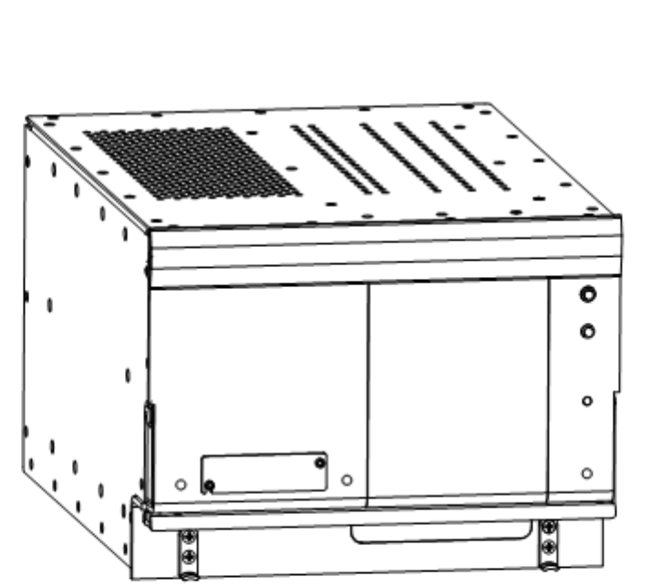
4. Illustration of Equipment Covered
Figure TC–1. HSD-128 Terminal
Page TC–6
18 September 2007
SYSTEM DESCRIPTION, INSTALLATION, AND MAINTENANCE MANUAL
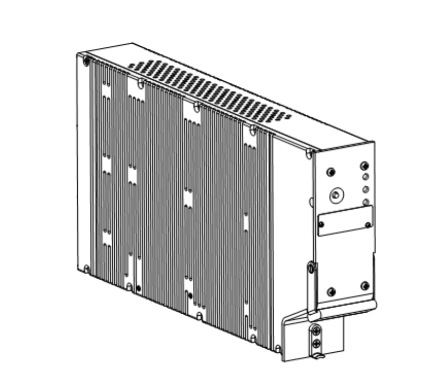
eNfusion™ HSD-128 High-speed Data Terminal
Figure TC–2. HSD-X SATCOM High-Speed-Data Transceiver Extension

Page 1–1
18 September 2007
SYSTEM DESCRIPTION, INSTALLATION, AND MAINTENANCE MANUAL
eNfusion™ HSD-128 High-speed Data Terminal
SYSTEM DESCRIPTION
1. Purpose of Equipment
The HSD is a scalable, high-speed-data, satellite communications terminal, which interfaces
with an ARINC 741-compatible antenna subsystem to provide a high-speed data
communication link with the Inmarsat satellite communication network. HSD transceivers are
available in single and dual channel models which can be installed in the following modes of
operation: Stand-Alone Mode, Combined/Selective Mode, and Cooperative Mode.
In Stand-Alone Mode HSD installations, the addition of HSD-X extension transceivers expands
the channel capacity by providing one additional voice or 64 kbps data channel—per HSD-X
to provide a Multi-Channel, high-speed data communication link with the Inmarsat satellite
communication network.
Table 1–1 shows the services that are supported by each HSD terminal.
Table 1–1. Supported Services Matrix for HSD-128, HSD-64, and HSD-X
Supported Services
and Functionality
HSD-128
(Stand-Alone,
Multi-Channel)
HSD-64/HSD-128
(Combined/Selective,
Cooperative)
HSD-X
(Multi-Channel
HSD)
Inmarsat Swift64 ISDN
(64 kbps UDI, 64 kbps
Speech, 56 kbps Data,
and 3.1 kHz audio)
YES YES YES
MPDS Over
RS-232
YES (with service
bulletin
1110-SB-0006)
YES (with service
bulletin 1110-SB-0006)
YES
Over
Ethernet
YES
(PNs 1110-A-0150,
1110-A-0160, and
HSD transceivers
with service bulletin
1110-SB-0006,
1110-SB-0004)
YES
(PNs 1110-A-0150,
1110-A-0160, and HSD
transceivers with
service bulletin
1110-SB-0006,
1110-SB-0004)
YES
AMBE® Mini-M Voice
(4.8 kbps)
YES NO YES
STU III (Encryption) YES (Full ISDN) YES (Full ISDN) YES (Full ISDN)
AMBE® STU YES (with channel
card software
version 6.0 (C41) or
later)
NO (Selective – YES) YES (with channel
card software
version 6.0 (C41) or
later)

Page 1–2
18 September 2007
SYSTEM DESCRIPTION, INSTALLATION, AND MAINTENANCE MANUAL
eNfusion™ HSD-128 High-speed Data Terminal
Ethernet Interface
(1110-A-0150 and
1110-A-0160 support the
Ethernet interface)
YES (with service
bulletin
1110-SB-0006 and
1110-SB-0004)
YES (with service
bulletin 1110-SB-0006
and 1110-SB-0004)
YES
Bonding Functionality YES NO - Not supported in
single-channel units
and Cooperative Mode
NO - Not supported
in single-channel
units
Table 1–1. Supported Services Matrix for HSD-128, HSD-64, and HSD-X
Supported Services
and Functionality
HSD-128
(Stand-Alone,
Multi-Channel)
HSD-64/HSD-128
(Combined/Selective,
Cooperative)
HSD-X
(Multi-Channel
HSD)

Page 1–3
18 September 2007
SYSTEM DESCRIPTION, INSTALLATION, AND MAINTENANCE MANUAL
eNfusion™ HSD-128 High-speed Data Terminal
2. Equipment Covered
A. Hardware Description
Table 1–2 provides a comparison of the Hardware variants of HSD and HSD-X
transceivers. Table 1–3 lists and describes all models of HSD transceivers covered in this
manual.
Table 1–2. HSD Transceiver Variants
Model Assembly
PN
Channel
Card(s)
Operational
Modes/
Configurations
Interconnection
Diagram
Voltage
(nominal)
Power
(nom/
max)
HSD-128 1110-A-0001 2 Stand-Alone 1110-B-0019 28 V dc 275/370 W
Multi-Channel
Configuration (with
Service Bulletin
1110-SB-0012
accomplished)
1110-B-0419
HSD-128 1110-A-0060 2 Stand-Alone 1110-B-0019 115 V ac/
400 Hz
275/385 W
Multi-Channel
Configuration (with
Service Bulletin
1110-SB-0012
accomplished)
1110-B-0419
HSD-128 1110-A-0001 2 Selective/Honeywell
Combined (with
Service Bulletin
1110-SB-0005
accomplished)
1110-B-0081 28 V dc 325/370 W
Collins Co-operative 1110-B-0156
HSD-128 1110-A-0060 2 Selective/Honeywell
Combined (with
Service Bulletin
1110-SB-0005
accomplished)
1110-B-0081 115 V ac/
400 Hz
325/385 W
Collins Co-operative 1110-B-0156
HSD-128 1110-A-0150 2 Stand-Alone 1110-B-0019 115 V ac/
400 Hz
325/385 W
Collins Co-operative 1110-B-0156
Selective/Honeywell
Combined
1110-B-0081
Multi-Channel
Configuration
1110-B-0419

Page 1–4
18 September 2007
SYSTEM DESCRIPTION, INSTALLATION, AND MAINTENANCE MANUAL
eNfusion™ HSD-128 High-speed Data Terminal
HSD-128 1110-A-0160 2 Stand Alone 1110-B-0081 28 V dc 275/370 W
Collins Co-operative 1110-B-0156
Selective/Honeywell
Combined
1110-B-0081
Multi-Channel
Configuration
1110-B-0419
HSD-64 1110-A-0080 1 Selective/Honeywell
Combined (with
Service Bulletin
1110-SB-0005
accomplished)
1110-B-0081 28 V dc 275/370 W
Collins Co-operative 1110-B-0156
HSD-64 1110-A-0070 1 Selective/Honeywell
Combined (with
Service Bulletin
1110-SB-0005
accomplished)
1110-B-0081 115 V ac/
400 Hz
275/385 W
Collins Co-operative 1110-B-0156
HSD-X 1110-A-0401 1 Multi-Channel
Extension
Configuration with
HSD-128
Transceiver
1110-B-0419 115 V ac/
400 Hz
30/40 W
Table 1–2. HSD Transceiver Variants
Model Assembly
PN
Channel
Card(s)
Operational
Modes/
Configurations
Interconnection
Diagram
Voltage
(nominal)
Power
(nom/
max)
Table 1–3. Equipment Covered
Model Description
HSD-128 PN 1110-A-0001
HSD High-speed Data SATCOM Transceiver: High-speed data terminal
containing two channel cards, a control processor, a high power amplifier, and
a +28 V dc power supply. Operates with an Aero H/H+ (ARINC 741 compatible)
antenna subsystem to provide circuit (Swift64 Mobile ISDN), packet-switched
HSD (Swift64 MPDS), and Mini-M AMBE services over the Inmarsat satellite
communications network.
HSD-128 PN 1110-A-0060
HSD High-speed Data SATCOM Transceiver: High-speed data terminal
containing two channel cards, a control processor, a high power amplifier, and
a 115 V ac, 400 hertz (Hz) power supply. Operates with an Aero H/H+ (ARINC
741 compatible) antenna subsystem to provide circuit (Swift64 Mobile ISDN),
packet-switched HSD (Swift64 MPDS), and Mini-M AMBE services over the
Inmarsat satellite communications network.

Page 1–5
18 September 2007
SYSTEM DESCRIPTION, INSTALLATION, AND MAINTENANCE MANUAL
eNfusion™ HSD-128 High-speed Data Terminal
B. Software Description
This section describes the software specifications and operational software components
of the HSD and HSD-X transceivers. It also describes the software requirements and
compatibility issues for each mode of operation.
(1) Software Specifications
The operating software of the HSD and HSD-X transceivers meets with
RTCA/DO-178B Level E requirements.
HSD-128 PN 1110-A-0150
HSD High-speed Data SATCOM Transceiver: High-speed data terminal
containing two channel cards, a control processor, a Data I/O Type 2 card, a high
power amplifier, and a 115 V ac, 400 hertz (Hz) power supply. Operates with an
Aero H/H+ (ARINC 741 compatible) antenna subsystem to provide circuit
(Swift64 Mobile ISDN), packet-switched HSD (Swift64 MPDS), and Mini-M
AMBE services over the Inmarsat satellite communications network. Supports
Ethernet connections.
HSD-128 PN 1110-A-0160
HSD High-speed Data SATCOM Transceiver: High-speed data terminal
containing two channel cards, a control processor, a Data I/O Type 2 card, a high
power amplifier, and a a +28 V dc power supply. Operates with an Aero H/H+
(ARINC 741 compatible) antenna subsystem to provide circuit (Swift64 Mobile
ISDN), packet-switched HSD (Swift64 MPDS), and Mini-M AMBE services over
the Inmarsat satellite communications network. Supports Ethernet connections.
HSD-64 PN 1110-A-0070
HSD High-speed Data SATCOM Transceiver: High-speed data terminal
containing one channel card, a control processor, a high power amplifier, and a
115 V ac, 400 hertz (Hz) power supply. Operates with an Aero H/H+ (ARINC 741
compatible) antenna subsystem to provide circuit (Swift64 Mobile ISDN),
packet-switched HSD (Swift64 MPDS), and
Mini-M AMBE services over the Inmarsat satellite communications network.
HSD-64 PN 1110-A-0080
HSD High-speed Data SATCOM Transceiver: High-speed data terminal
containing one channel card, a control processor, a high power amplifier, and a
+28 V dc power supply. Operates with an Aero H/H+ (ARINC 741 compatible)
antenna subsystem to provide circuit (Swift64 Mobile ISDN), packet-switched
HSD (Swift64 MPDS), and Mini-M AMBE services over the Inmarsat satellite
communications network.
HSD-X PN 1110-A-0401
The HSD-X High-speed Data SATCOM Transceiver Extension contains a single
channel card, a High Stability Reference, an Output Amplifier, a Data Processor
module, and a 115 V ac 400 hertz (Hz) power supply. It operates in conjunction
with an HSD-128 transceiver to provide Inmarsat Swift64 services and Mini-M
AMBE voice services. This transceiver supports Multi-Channel HSD
configurations by adding additional channels to HSD-128 systems.
Table 1–3. Equipment Covered
Model Description
Page 1–6
18 September 2007
SYSTEM DESCRIPTION, INSTALLATION, AND MAINTENANCE MANUAL
eNfusion™ HSD-128 High-speed Data Terminal
(2) Operational Software Part Numbers
Table 1–4 provides a list of software part numbers for the HSD transceiver. Table 1–
5 provides a list of software part numbers for the HSD-X transceiver.
(3) Operational Mode Software Requirements
This section describes the software requirements and compatibility issues for each
mode of operation, including Multi-Channel configurations.
(a) Stand-Alone Mode
For Stand-Alone Mode installations, the minimum and recommended
requirements for software are shown in Table 1–6.
Table 1–4. HSD Operational Software
EMS SATCOM Part
Number Description
LI-1110-10136 HSD-64/128 Software Configuration
1110-A-0082 Aero Channel Card Software
1110-A-0048 Assembly Firmware Control Processor
1110-A-0109 Firmware HPA 28 V dc
1110-A-0110 Firmware HPA 115 V ac
1110-A-0129 Firmware HPA 28 V dc Revised Board
1110-A 0141 Firmware HPA 115 V ac Revised Board
1110-A-0100 HSD Data I/O Firmware Assembly (Only applies to units
with Data I/O Card Type 2 installed)
Table 1–5. HSD-X Operational Software
EMS SATCOM Part
Number Description
LI-1110-10181 HSD-X Software Configuration
1110-A-0082 Aero Channel Card Software
1110-A-0420 Assembly Firmware Control Processor
1110-A-0115 HSD-X Data I/O Firmware
1110-A-0085 M4 Combined Pic and Bootloader
Table 1–6. Stand-Alone Mode Minimum Software Requirements
Unit Part
Number
Software
PN
Software
Type
Minimum
Software
Req’t
Recommended
Software
HSD-128 1110-A-0001
1110-A-0060
1110-A-0150
1110-A-0160
1110-A-0048 Control
Processor
4.1 7.5 (or later)
1110-A-0082 Channel
Card
C24 C41 (or later)

Page 1–7
18 September 2007
SYSTEM DESCRIPTION, INSTALLATION, AND MAINTENANCE MANUAL
eNfusion™ HSD-128 High-speed Data Terminal
(b) Combined Mode
For Combined Mode installations, the minimum requirement for HSD
Control-Processor software is version 5.4 (or later) to use ARINC 429 data from
the Honeywell SDU. Version 5.4, Control-Card software is available via HSD
Service Bulletin, 1110-SB-0012. The minimum requirements and
recommendations for software are shown in Table 1–7.
(c) Cooperative Mode
For Cooperative Mode installations, the minimum requirements and
recommendations for software are shown in Table 1–8.
(d) Selective Mode
Selective Mode is a non-standard installation and it is not a recommended mode
of operation. Selective Mode has been superseded by Combined Mode
operation for MCS series SATCOM and with Cooperative Mode operation for
SAT-906 series SATCOM. It is recommended that all systems operating in
Selective Mode are upgraded to support Combined or Cooperative Mode as
applicable.
For Selective Mode installations, the minimum requirements and
recommendations for software are shown in Table 1–9.
Table 1–7. Combined Mode Recommended Software Requirements
Unit Part
Number
Software
PN
Software
Type
Minimum
Software
Req’t
Recommended
Software
HSD-128 1110-A-0001
1110-A-0060
1110-A-0150
1110-A-0160
1110-A-0048 Control
Processor
5.7 7.5 (or later)
1110-A-0082 Channel
Card
C35 C41 (or later)
Table 1–8. Cooperative Mode Recommended Software Requirements
Unit Part
Number
Software
PN
Software
Type
Minimum
Software
Req’t
Recommended
Software
HSD-128 1110-A-0001
1110-A-0060
1110-A-0150
1110-A-0160
1110-A-0048 Control
Processor
5.7 7.5 (or later)
1110-A-0082 Channel
Card
C35 C41 (or later)

Page 1–8
18 September 2007
SYSTEM DESCRIPTION, INSTALLATION, AND MAINTENANCE MANUAL
eNfusion™ HSD-128 High-speed Data Terminal
(e) Multi-Channel Configurations
In a Multi-Channel configuration, the minimum requirement for HSD-128 Control
Processor software is version 7.0. Version 7.0, Control Processor software is
available via HSD Service Bulletin 1110-SB-0012. HSD-X Transceiver
Extensions require Control Processor software version 6.0.
In Multi-Channel configurations, both the HSD-128 and the HSD-X units must
have the same Channel Card and Data I/O software versions installed. When
upgrading software in either the HSD-128 or HSD-X, verify that the software
version is compatible for operation in Multi-Channel systems as indicated in the
applicable service bulletin.
The minimum requirements and recommendations for software are shown in
Table 1–10.
(4) Software Version Description
This section provides a brief description of the deltas between versions of operational
software. Table 1–11 provides a matrix of software versions, applicable service
bulletins, compliance requirements, and a brief description of the software deltas.
Table 1–9. Selective Mode Minimum Software Requirements
Unit Part
Number
Software
PN
Software
Type
Minimum
Software
Req’t
Recommended
Software
HSD-128 1110-A-0001
1110-A-0060
1110-A-0150
1110-A-0160
1110-A-0048 Control
Processor
5.7 7.5 (or later)
1110-A-0082 Channel
Card
C35 C41 (or later)
Table 1–10. Multi-Channel Configuration Recommended Software Requirements
Unit Part
Number
Software
PN
Software
Type
Minimum
Software
Req’t
Recommended
Software
HSD-128 1110-A-0001
1110-A-0060
1110-A-0150
1110-A-0160
1110-A-0048 Control
Processor
7.0 7.5 (or later)
1110-A-0082 Channel
Card
6.0 (C41) 6.0 (C41) (or
later)
HSD-X 1110-A-0401 1110-A-0420 Control
Processor
6.0 6.0 (or later)
1110-A-0082 Channel
Card
6.0 (C41) 6.0 (C41) (or
later)
1110-A-0240 Data I/O
Software
115 Superceded by
1110-A-0115
1110-A-0115 Data I/O
HSD-X
117 117

Page 1–9
18 September 2007
SYSTEM DESCRIPTION, INSTALLATION, AND MAINTENANCE MANUAL
eNfusion™ HSD-128 High-speed Data Terminal
Table 1–12 provides a service bulletin matrix to list the applicability of all service
bulletins released against the HSD and HSD-X units as of the release date of this
manual.
Table 1–11. Description of Control Processor Software Changes
Control
Processor
Software
Version
Applicable
Service
Bulletin
Compliance
Requirements Description of Change
4.4 1110-SB-0001 Control card release
with mandatory
channel card
change from C24 to
C30
Ensures channel card is
powered down for 5 seconds
after a fatal error. Channel
card software change from
C24 to C30
4.5 1110-SB-0003 Mandatory for all
units operating in
Cooperative Mode
installs with Collins
SAT-906 systems.
Resolves the problem
occurring during the power
up sequence, the SAT-906
system reports error 0100,
1000, and 0800, which
results in the deactivation of
the HSD channel cards.
4.6 N/A N/A Adds menu command to
specify manual satellite
longitude. Ensures that
manually specified ocean
regions are maintained. This
version does not support
Cooperative Mode (with
SAT-906).
5.4 1110-SB-0005 Mandatory for units
installed in
Combined Mode
with Honeywell
Aero H Satcom
systems. Optional
for all other units.
Upgrades the hardware for
Honeywell Combined Mode
(HCM) to include a RF
detector and a variable
attenuator on the Aero H path
of the pre-HPA combiner and
allows the reading and
control of this attenuator
through a serial connection to
the combiner.
This version does not support
Cooperative Mode (with
SAT-906).

Page 1–10
18 September 2007
SYSTEM DESCRIPTION, INSTALLATION, AND MAINTENANCE MANUAL
eNfusion™ HSD-128 High-speed Data Terminal
5.7 1110-SB-0011 Recommended for
all units operating in
Cooperative Mode
with Collins Sat-906
systems, optional
for all other units.
Upgrades the Channel Card
software to version C35 to fix
Cooperative Mode bug in
Channel Card software
version C30. Upgrades
software to recognize
Cooperative Mode System
Config hardware strapping.
6.5 1110-SB-0007 Generic release
suitable for all
modes of HSD
operation
Compatible with
HSD-X version 6.0
firmware.
Upgrades the HSD-128
Control Processor software
to version 6.5. This version
adds the Multi-Channel
capability to the HSD-128
software to support HSD-128
units integration with external
HSD-X channels (PN
1110-A-0401).
Table 1–11. Description of Control Processor Software Changes
Control
Processor
Software
Version
Applicable
Service
Bulletin
Compliance
Requirements Description of Change

Page 1–11
18 September 2007
SYSTEM DESCRIPTION, INSTALLATION, AND MAINTENANCE MANUAL
eNfusion™ HSD-128 High-speed Data Terminal
7.0 1110-SB-0012 Recommended for
units operating in
multi-channel
configurations with
HSD transceivers.
Optional for all other
units and system
modes.
Upgrades the channel card
software to version C41 (6.0)
which supports enhanced
HSD functionality in all
modes of operation,
(including Multi-Channel
configurations and AMBE
STU capability). In
Cooperative Mode systems,
MPDS is not supported with
this version of software.
Upgrades the control
processor software to version
7.0, which enhances all
modes of operation.
Selective Mode units
operating Category A
Inmarsat terminals may
experience GPS faults when
operating this version of
software.
Contact EMS SATCOM
Product Support for details.
7.5 1110-SB-0015 Highly
recommended for
units operation in
Cooperative Mode
with Rockwell
Collins SAT-906
systems. Optional
for Stand-Alone
units and all other
operational modes.
HSD Control Processor
software version 7.5 includes
fixes specific to Cooperative
Mode operation problems
and enhances unit operation.
Table 1–11. Description of Control Processor Software Changes
Control
Processor
Software
Version
Applicable
Service
Bulletin
Compliance
Requirements Description of Change

Page 1–12
18 September 2007
SYSTEM DESCRIPTION, INSTALLATION, AND MAINTENANCE MANUAL
eNfusion™ HSD-128 High-speed Data Terminal
Table 1–12. Service Bulletin Matrix
Service
Bulletin
PN 1110-A-0001
PN 1110-A-0060
PN 1110-A-0070
PN 1110-A-0080
PN 1110-A-0150
PN 1110-A-0160
PN 1110-A-0401
Description
1110-SB-0001 X X X X Software upgrade to
accommodate Inmarsat
system changes
1110-SB-0002 X X X X HPA Mute and ARINC 429
Driver Modifications
1110-SB-0003 X Upgrade to HPA software
and Control Processor
software to fix Cooperative
Mode SAT-906 system
reporting errors (Version
4.5)
1110-SB-0004 X X X X Data I/O Type 2 upgrade
option
1110-SB-0005 X X X X Hardware modification and
software upgrade for
Combined Mode operation
1110-SB-0006 X X X X Software upgrade to
support MPDS service
(Version C35)
1110-SB-0007 X X Software upgrade for
Multi-Channel (Version 6.5)
1110-SB-0008 N/A
1110-SB-0009 N/A
1110-SB-0010 X X Optional hardware upgrade
to dual channel transceiver
and support for STU III and
Mini-M Voice (Version C41)
1110-SB-0011 X X X X Software upgrade for
Cooperative Mode
1110-SB-0012 X X X X Software upgrade to add
AMBE STU support and
enhances performance of
all modes of operation
(Version 7.0)
1110-SB-0013 X X X X X X Addition of a software
identification label to all
units

Page 1–13
18 September 2007
SYSTEM DESCRIPTION, INSTALLATION, AND MAINTENANCE MANUAL
eNfusion™ HSD-128 High-speed Data Terminal
1110-SB-0014 X X X X X X Upgrades Data I/O Type 2
software to fix susceptibility
to certain malformed traffic,
which caused PPPoE
sessions to “hang-up”
leaving the call connected
1110-SB-0015 X X X X X X Upgrades control
processor software to
enhance Cooperative
Mode operation (Version
7.5)
1110-SB-0401 X Software upgrade to add
AMBE STU capability,
enhance system operation,
including with MPDS
1110-SB-0402 X Addition of a software
identification label to all
units
1110-SB-0403 X Upgrades Data I/O Type
software to fix susceptibility
to certain malformed traffic,
which caused PPPoE
sessions to “hang-up”
leaving the call connected
Table 1–12. Service Bulletin Matrix
Service
Bulletin
PN 1110-A-0001
PN 1110-A-0060
PN 1110-A-0070
PN 1110-A-0080
PN 1110-A-0150
PN 1110-A-0160
PN 1110-A-0401
Description

Page 1–14
18 September 2007
SYSTEM DESCRIPTION, INSTALLATION, AND MAINTENANCE MANUAL
eNfusion™ HSD-128 High-speed Data Terminal
3. Equipment Description
This section describes the physical and environmental specifications of the equipment.
A. Applicable Documents
• High speed data terminal Setup Guide, EMS SATCOM PN MN-1110-10048
• ARINC 741. ARINC Report 413A – Guidance for Aircraft Electrical Power Utilization
and Transient Protection, Attachment 3-2, Wire Shielding and Grounding
Requirements and Appendix 7
B. Reference Documents
• HSD-64/128 Software Control Document, EMS SATCOM PN LI-1110-10136
• HSD-X Software Control Document, EMS SATCOM PN LI-1110-10181
C. Equipment Specifications
This section provides the equipment specifications for the HSD and HSD-X transceivers.
Table 1–13 lists the physical and equipment specifications for the HSD transceiver. Table
1–14 lists the RTCA/DO-160D environmental characteristics and specifications for the
HSD transceiver.
Table 1–15 lists the physical and equipment specifications for the HSD-X transceiver.
Table 1–16 lists the RTCA/DO-160D environmental characteristics and specifications for
the HSD-X transceiver.
Table 1–13. HSD Equipment Characteristics and Specifications
CHARACTERISTIC SPECIFICATION
Certification/related documents
ARINC characteristics 600-12, Air Transport Avionics Equipment
Interfaces, December 12, 1998
Appendix 10 of the ARINC 704-7
RTCA documents RTCA/DO-160D, Environmental Conditions and
Test Procedures for Airborne Equipment, July 29,
1997
HSD Software RTCA/DO-178B Level E
Physical Size
Height 19.93 cm (7.85 in)
Width 25.91 cm (10.20 in)
Length 36.45 cm (14.58 in)
Weight 13 Kg (28.7 lbs)
Mounting information 8 MCU Tray (per ARINC 600, 8 MCU LRU)
Maintenance requirements No scheduled maintenance is required
Electrical specifications

Page 1–15
18 September 2007
SYSTEM DESCRIPTION, INSTALLATION, AND MAINTENANCE MANUAL
eNfusion™ HSD-128 High-speed Data Terminal
HSD-128 dc input power
1110-A-0001, 1110-A-0160
Voltage Minimum: 22 V dc
Typical: 27.5 V dc
Maximum: 30.3 V dc
Power dissipation
(Stand-Alone)
Minimum: 275 W
Maximum: 370 W
Power dissipation
(Selective, Combined, and
Cooperative)
Minimum: 325 W
Maximum: 370 W
HSD-128 ac input power
1110-A-0060, 1110-A-0150
Voltage Minimum: 100 V rms
Typical: 115 V rms
Maximum: 122 V rms
Power dissipation
(Stand-Alone)
Minimum: 275 W
Maximum: 385 W
Power dissipation
(Selective, Combined, and
Cooperative)
Minimum: 325 W
Maximum: 385 W
Frequency Minimum: 360 Hz (Typical: 400 Hz)
Maximum: 440 Hz
HSD-64 dc input power
1110-A-0080
Voltage Minimum 22 V dc (Typical 27.5 V dc)
Maximum 30.3 V dc
Power dissipation Minimum: 275 W
Maximum: 370 W
HSD-64 ac input power
1110-A-0070
Voltage Minimum 100 V rms (Typical 115 V rms)
Maximum 122 V rms
Power dissipation
Frequency
Frequency band
Minimum: 275 W
Maximum: 385 W
Minimum: 360 Hz (Typical: 400 Hz)
Maximum: 440 Hz
Tx: 1626.5 to 1660.5 MHz
Rx: 1525.0 to 1559.0 MHz
Power requirements HSD
PN 1110-A-0001, 1110-A-0080,
1110-A-0160
+ 28 V dc nominal @ 13.5A
Table 1–13. HSD Equipment Characteristics and Specifications
CHARACTERISTIC SPECIFICATION

Page 1–16
18 September 2007
SYSTEM DESCRIPTION, INSTALLATION, AND MAINTENANCE MANUAL
eNfusion™ HSD-128 High-speed Data Terminal
PN 1110-A-0060, 1110-A-0070,
1110-A-0150
115 V ac, 400 Hz (nominal) @5A
Wire gage dc power: 12 American Wire Gauge (AWG)
ac power: 20 AWG (hot lead), 12 AWG (cold lead)
Signals: Unless otherwise specified, use 22 AWG
for all signal wires
Ground requirements ARINC 741
Heating and cooling requirements
Cooling air ARINC 600
Flow rate 175 lbs/hr
Pressure drop 0.05”, ± 0.025” H2O
Output frequency range (Transmit) Minimum: 1626.5 MHz
Maximum: 1660.5 MHz
Input frequency range (Receive) Minimum: 1530 MHz
Maximum: 1559 MHz
Receive input impedance 50 ohms
Transmit output impedance 50 ohms
VSWR 2:1 maximum
Maximum Output Power 18 dBW
Table 1–14. HSD RTCA/DO-160D Environmental Characteristics
CHARACTERISTIC SPECIFICATION
Environmental
Temp and altitude
In-flight loss of cooling
115 V ac units: Category A1, F2 V
28 V dc units: Category A1 F2 W
Temperature variation Category B (± 5°C/minimum)
Humidity Category A (95%, 48 hours)
Shock Category B (6g/20g, 11ms)
Vibration Category SB (1.48grms)
Explosion proofness Category E
Waterproofness Category X (not applicable)
Fluids susceptibility Category X (not applicable)
Sand and dust Category X (not applicable)
Fungus resistance Category F
Salt spray Category X (not applicable)
Magnetic effect 115 V ac units: Category Z (< 1.0m)
28 V dc units: Category A (<1.0m)
Power input Categoriy A
Table 1–13. HSD Equipment Characteristics and Specifications
CHARACTERISTIC SPECIFICATION

Page 1–17
18 September 2007
SYSTEM DESCRIPTION, INSTALLATION, AND MAINTENANCE MANUAL
eNfusion™ HSD-128 High-speed Data Terminal
Voltage spike 115 V ac units: Category A
28 V dc units: Category A
Audio frequency susceptibility 115 V ac units: Category A
28 V dc units: not tested
Induced signal susceptibility 115 V ac units: Category Z
28 V dc units: not tested
RF susceptibility 115 V ac units: Category RR
28 V dc units: not tested
Emission of RF Energy 115 V ac units: Category B
28 V dc units: Category B
Lightning Direct Effects Category X (not applicable)
Icing Category X (not applicable)
Table 1–15. HSD-X Transceiver Specifications
CHARACTERISTIC SPECIFICATION
Certification/related documents
ARINC characteristics 600-12, Air Transport Avionics Equipment
Interfaces, December 12, 1998
Appendix 10 of the ARINC 704-7
RTCA documents RTCA/DO-160D, Environmental Conditions
and Test Procedures for Airborne Equipment,
July 29, 1997
HSD-X Software RTCA/DO-178B Level E
Physical
Size 2 MCU ARINC 600-10 Form Factor
Weight 8.8 lbs maximum
Cooling air Unit capable of continuous duty cycle operation,
with or without forced air-cooling provided, as
per ARINC 600 specifications. Refer to
1110-E-0401. (See "Installation" on page 3-1.)
Mounting Information As per ARINC 600 specifications. Refer to
1110-E-0401. (See "Installation" on page 3-1.)
Maintenance Requirements No maintenance requirements
Electrical
Power Dissipation 34 Watts
Input Power 115 V ac, 400 Hz, 75 va
Input frequency range 1530.0 to 1559.0 MHz
Output frequency range 1626.5 to 1660.5 MHz
Receiver input impedance 50 ohms
Table 1–14. HSD RTCA/DO-160D Environmental Characteristics
CHARACTERISTIC SPECIFICATION

Page 1–18
18 September 2007
SYSTEM DESCRIPTION, INSTALLATION, AND MAINTENANCE MANUAL
eNfusion™ HSD-128 High-speed Data Terminal
Transceiver output impedance 50 ohms
VSWR 2:1 maximum
Input level operational
Input level no damage
-107 dBm to -47 dBm
+10 dBm
External (Digital) Interfaces
Crosstalk Bus ARINC 429 high-speed (100 kbps) data bus
Maintenance Port RS-232 Data
loader
Front and Rear Connector
RS-232 serial bus supporting 57.6 kbps data
load capacity
ISDN User Interface 64 kbps ISDN Euro input and output
Table 1–16. HSD-X RTCA/DO-160D Environmental Specifications
CHARACTERISTIC SPECIFICATION
Temperature and Altitude Categories: A4 (without cooling air)/ C4 (with
cooling air)
Low operating temperature -40 °C (A4), -40 °C (C4)
High operating temperature +55 °C (A4), +70 °C (C4)
Altitude Maximum operating altitude: 15,000 ft
(A4)/55,000 ft (C4)
Loss of cooling Category Y
Temperature Variation Category B
Humidity Category A
Shock Category B
Vibration Category SB
Explosion Proofness Category E
Waterproofness Category X
Fluids Susceptibility Category X
Sand and Dust Category X
Fungus Resistance Category F
Salt Spray Category X
Magnetic Effect Category Z
Power Input Category A
Voltage Spike Category A
Audio Frequency Category A
Induced Signal Category C
RF Susceptibility Category RR
Table 1–15. HSD-X Transceiver Specifications
CHARACTERISTIC SPECIFICATION
Page 1–19
18 September 2007
SYSTEM DESCRIPTION, INSTALLATION, AND MAINTENANCE MANUAL
eNfusion™ HSD-128 High-speed Data Terminal
D. Mechanical Description
This section describes the mechanical characteristics of the HSD and HSD-X
transceivers.
(1) HSD Transceiver
The HSD transceiver is an 8-MCU sized unit with mounting requirements according
to the ARINC 600 specification. The front panel has one, socket D-Type size B (25
contacts) maintenance port connector (under protective cover) for data loading and
monitoring of the unit. Two front-panel LEDs indicate unit status.
The rear connector complies with ARINC 600, shell size 2 and has three inserts: upper,
middle, and bottom. The upper and middle inserts each have one #1 coax contact
and seventy, 22-gauge signal contacts. The bottom insert connector has contact with
only positions 1, 2, 3, 7, 8, and 12. The rear panel has three polarization points.
For detailed wiring information, refer to the interconnection diagrams and contact
assignments for each installation mode presented in "Installation" on page 3-1 as
noted below:
(2) HSD-X Transceiver
The HSD-X is a 2-MCU sized unit with mounting requirements according to the ARINC
600 specification. The front panel has one, female, micro-D type connector for data
loading and monitoring of the unit. Three front panel LEDs illuminate to indicate unit
functionality as described in detail in "Test and Fault Isolation" on page 4-1.
Emission of RF Energy Category M
Lightning Induced Transient
Susceptibility
Category A3E3
Lightning Direct Effects Category X
Icing Category X
Electrostatic Discharge Category A
Table 1–16. HSD-X RTCA/DO-160D Environmental Specifications
CHARACTERISTIC SPECIFICATION
Table 1–17. HSD Installation Mode Drawing Reference Matrix
Installation Mode Installation Section Figure Figure Description
Stand-Alone Figure 3–29 System Interconnect
Figure 3–30 Contact Assignments
Combined/Selective Figure 3–31 System Interconnect
Figure 3–32 Contact Assignments
Cooperative Figure 3–33 System Interconnect
Figure 3–34 Contact Assignments
Stand-Alone HSD in
Multi-Channel
Configuration
Figure 3–35 and Figure 3–36 System Interconnect
Figure 3–37 and Figure 3–38 Contact Assignments
Page 1–20
18 September 2007
SYSTEM DESCRIPTION, INSTALLATION, AND MAINTENANCE MANUAL
eNfusion™ HSD-128 High-speed Data Terminal
The rear connector complies with ARINC 600, shell size 1. The connector top and
middle cavities have 60 number 22 interconnects, while the bottom cavity has two
number 16 interconnects, one number 12 interconnect, and two RF interconnects.
E. Electrical Description
This section describes the external electrical interfaces of the HSD and HSD-X
transceivers. General system block diagrams of the avionics and antenna subsystem are
presented in Figure 1–10, Figure 1–11, Figure 1–12, and Figure 1–13.
"Installation" on page 3-1 describes all ARNC 600 connector contact assignments and
physical details, including part numbers, insert descriptions, and polarization keying.
The loading/gradient specifications for all HSD installation modes, including Stand-Alone
Mode, Multi-Channel configurations with HSD-X transceivers, are provided in table format
in "Installation" on page 3-1. These tables list all of the ARINC Top, Middle, and Bottom
Plug pin designations as well as provide installation connection details.
(1) General
The HSD contains a communications switch (SW) that supports Inmarsat Swift64
Mobile ISDN and MPDS service within an 8-MCU assembly built in accordance to
ARINC 600 specifications.
The HSD-X contains a communications switch (SW) that supports Inmarsat Swift64
Mobile ISDN and MPDS service within a 2-MCU assembly built in accordance to
ARINC 600 specifications.
(a) Stand-Alone Mode
The HSD L-Band Rx/Tx input and outputs interface directly with the DLNA. The
HSD uses the ARINC 429 multi-control bus to interface with the ACU/BSU to
control the RF antenna and obtain antenna-subsystem status information. The
HSD receives the required navigational data, provided by the aircraft Inertial
Navigational System (INS), from the ARINC 429 IRS bus. The aircraft supplies
either 28 V dc or 115 V 400 Hz power to the HSD.
(b) Non-Stand-Alone Modes (Cooperative, Combined, Selective)
The HSD L-band Rx/Tx interface combiners are shared with those of the
SATCOM H/H+ system via splitters after the DLNA and before the high power
amplifier (HPA). The Aero H/H+ system, that the HSD is installed with, controls
the antenna subsystem and the RF transmit signal attenuation in the High-Gain
Antenna HPA of the HSD through the SDU multi-control ARINC 429 bus. The
aircraft supplies either 28 V dc or 115 V 400 Hz power to the HSD.
(c) Multi-Channel Configurations with HSD-X Transceivers
The HSD Multi-Channel configuration combines a dual-channel, Stand-Alone
Mode, HSD-128 Transceiver with one or more single-channel HSD-X
Transceivers to add additional channels to the system.
Each channel provides an ISDN 64 kbps connection that can be used for voice
or data services. The two channels in the HSD-128 can be internally bonded to
provide a 128 kbps ISDN data connection. Externally, all four channels shown
in Multi-Channel System Block Diagram on page 40 can be combined to provide
a single 256 kbps capability with the help of a router, Ethernet hub, or Terminal
Adapter.
Page 1–21
18 September 2007
SYSTEM DESCRIPTION, INSTALLATION, AND MAINTENANCE MANUAL
eNfusion™ HSD-128 High-speed Data Terminal
The HSD-128 is the master of the system; it controls the overall operation of the
Multi-Channel HSD configuration. It keeps track of time and allocated power and
may command the HSD-X units to terminate calls under certain conditions, such
as an ocean region change. The HSD-X units are wired to the HSD-128 HPA
and therefore compete equally for HPA power allocation.
The transmit signal of each channel is fed through combiners/attenuators
combinations to the HPA located in the HSD and ultimately to the antenna.
Conversely, the receive signal from the antenna goes through a series of splitters
on its way to each channel.
On power-up, HSD-X channels go through an initialization process that identifies
and communicates the number of HSD-X channels and their position in the
system chain back to the HSD-128 master.
The block diagram in Figure 1–10 illustrates the system function of the HSD-128,
two HSD-Xs, and the antenna system.
(2) Pin and Connector Descriptions
Detailed pin and connector descriptions for both HSD and HSD-X transceivers are
provided for all installation modes and configurations in "Installation" on page 3-1.
F. System Interface Descriptions
This section briefly describes the external HSD and HSD-X system interfaces. The system
interfaces are those required to control, monitor, maintain, and supplement the unit’s
functionality. "Installation" on page 3-1 provides a detailed description of interface
connections.
(1) HSD System Interfaces
This section describes the system interfaces of HSD transceivers. Detailed
information on the splitter and combiner specifications and losses, as well as cabling
notes and system interconnections for all operational modes for HSD transceivers are
provided in "Installation" on page 3-1.
(a) HSD Source Destination Identification (SDI)
1. Stand-Alone Mode and Multi-Channel Configuration
Source/Destination Identification (SDI) is provided to the HPA as per ARINC
741 specifications.
2. Non-Stand-Alone Mode
Source/Destination Identification (SDI) is provided to the HPA as per ARINC
741 specifications.
(b) HSD Forward and Return Address IDs
The HSD uses two 24-bit IDs called “Forward Link Pairs” (FRLPs): a Forward ID
(Fwd ID) and a Return (Rtn) ID per pair. The HSD reads the Fwd ID and performs
a look-up for the Rtn ID. For security reasons, each assembly contains an
encrypted look-up table with the whole addressing space assigned to the product
by Inmarsat. To minimize the risk of unauthorized use of its contents, the table
is not accessible to the user.

Page 1–22
18 September 2007
SYSTEM DESCRIPTION, INSTALLATION, AND MAINTENANCE MANUAL
eNfusion™ HSD-128 High-speed Data Terminal
The 24-bit Fwd ID strap pins, available on the ARINC 600 connector, form part
of the Inmarsat serial number (ISN). The ISN consists of the type approval
number and the Fwd ID address. Each FRLP is associated with Inmarsat Mobile
Numbers (IMN), which are the numbers that a user dials from the ground to reach
the terminal on an aircraft. There is a unique IMN for each of the service types
(e.g. data, voice, Fax).
(c) HSD WOW Pin Wiring
Weight-On-Wheel (WOW) discretes indicate when an aircraft is on the ground
and are used for flight data-logging purposes. Note 40 of ARINC 741 defines the
WOW pins.
(d) HSD IRS ARINC 429 Interface
Table 1–18 shows the IRS ARINC 429 bus labels and associated data types. For
more details on characteristics, refer to Appendix 10 of the ARINC 704-7, Inertial
Reference System document.
1. Stand-Alone Mode and Multi-Channel Configuration
In Stand-Alone Mode installations, the HSD requires high-speed ARINC 429,
IRS Navigational information (as shown in 17) to compute the azimuth,
elevation, and Doppler correction information required for antenna pointing.
2. Non-Stand-Alone Modes
In Combined and Selective Mode installations, the HSD uses aircraft IRS
information to determine which satellite to use, as selected by the Aero H/H+
SDU.
In Cooperative Mode installations, the HSD uses aircraft IRS information
received from the ARINC 741 SATCOM SDU via the SDU crosstalk ARINC
429 bus.
Table 1–18. ARINC 429 IRS Navigational Requirements
Label (octal) Name Interval Rate (ms)
Min. Max.
310 Latitude 100 200
311 Longitude 100 200
312 Ground Speed 25 50
313 True Track 25 50
314 True Heading 25 50
324 Pitch Angle 10 20
325 Roll Angle 10 20

Page 1–23
18 September 2007
SYSTEM DESCRIPTION, INSTALLATION, AND MAINTENANCE MANUAL
eNfusion™ HSD-128 High-speed Data Terminal
(e) HSD Antenna Interface
1. Stand-Alone Mode and Multi-Channel Configuration
In Stand-Alone installations, the HSD interfaces to any mechanically steered,
conformal-array, or phased array, ARINC 741-compatible, antenna
subsystems. The antenna-pointing commands and status messages are
communicated between the HSD and antenna subsystem over ARINC 429,
Multi-Control, Top/Port and/or Starboard BITE and HPA mute busses, as
defined in ARINC 741 Part 1.
2. Non-Stand-Alone Modes
In Non-Stand-Alone installations (Combined, Cooperative, and Selective
Modes), the ARINC 741 SATCOM SDU controls the satellite selection and
antenna pointing. The HSD monitors traffic on the Multi-Control, BSU, and
HPA mute busses to determine which satellite is used for the HSD’s channel
card(s) communication links. In Cooperative Mode, the HPA command and
status messages are communicated over the crosstalk lines.
(f) Antenna Subsystem RF Interface
In all installation modes, several external system RF parameters (such as cable
losses and antenna gain) are delimited to ensure that the HSD performance
requirements are met. Refer to "Installation" on page 3-1 for a definition of these
parameters and their expected values.
(g) RF Splitter: Non-Stand-Alone Mode Installations
In Non-Stand-Alone installations, an RF splitter must be installed to split the RF
Receive signal from the antenna subsystem’s DLNA between the Aero H Radio
Frequency Unit (RFU) and the HSD. (Refer the applicable section of "Installation"
on page 3-1 for specifications.)
(h) HSD Remote Status Panel (Optional)
The outputs to the optional “Remote Status Panel” provide a visual indication of
the operational status of the HSD; they “mirror” the LRU’s front panel LEDs
labeled as Power (LED1) and Fault (LED2) as defined in Table 1–19. Refer to
"Installation" on page 3-1 for detailed installation and circuit requirements.
(i) HSD Fault Conditions
A failure in the HSD may be due to a number of fault conditions. Upon detection
of a fault condition, the HSD activates its red, Fault LED. The potential fault
conditions are:
• Channel Card fault
Table 1–19. HSD LED Output Designations
LED
Signal Label LED Color Indication Description
LED1 Power Green Power On: HSD supply voltage is active.
Flashes at 1 Hz when the HPA is transmitting
LED2 Fault Red Fault: Fault condition as described in "HSD
Fault Conditions" on page 1-23
Page 1–24
18 September 2007
SYSTEM DESCRIPTION, INSTALLATION, AND MAINTENANCE MANUAL
eNfusion™ HSD-128 High-speed Data Terminal
• HPA fault
• External Reference Fault
• Internal ROM Fault
• Internal RAM Fault
• Over Temperature Fault
(j) HSD Remote Reset
The remote reset output provides an external reset function for the complete
HSD system. Pressing the momentary “normally open” (N.O.) switch resets the
system’s processor-card circuitry.
The remote reset has the same functionality as pressing the “test” button on the
front panel of the LRU.
CAUTION: Cooperative and Combined/Selective Mode installations and
HSD-X transceivers DO NOT support the use of the reset function.
If the HSD transceiver is reset in Cooperative or Combined Mode
installations, the communications between the HSD HPA and the
SDU of the Aero H/H+ system can be disrupted—potentially
causing the SATCOM system faults that may require the complete
reset of both systems.
(2) HSD-X Multi-Channel System Interfaces
This section describes the external interfaces unique to Stand-Alone Mode, HSD-128
Transceivers installed in a Multi-Channel configuration with HSD-X transceivers.
The following additional wiring is required for the installation of Multi-Channel HSD
systems.
• Splitter for the Rx path (See "Installation" on page 3-1)
• Combiner for the Tx path (See "Installation" on page 3-1)
• TPC1 must be installed on any HSD-128 ARINC 600 Trays that do not have TPC1
installed
• Forward ID Address as per HSD wiring
Detailed information on the splitter and combiner specifications and losses, as well
as cabling notes and system interconnections for Multi-Channel Configurations of
HSD and HSD-X transceivers are provided in "Installation" on page 3-1.
(a) Multi-Channel HSD-X Antenna Interface
Refer to "HSD Antenna Interface" on page 1-23.
(b) Weight-on-Wheels (WOW) (Optional)
Refer to "HSD WOW Pin Wiring" on page 1-22.
(c) HSD-X Forward ID
Like the HSD transceivers, the HSD-X units use Forward IDs (Fwd ID) to identify
the terminal to the Inmarsat communication network.
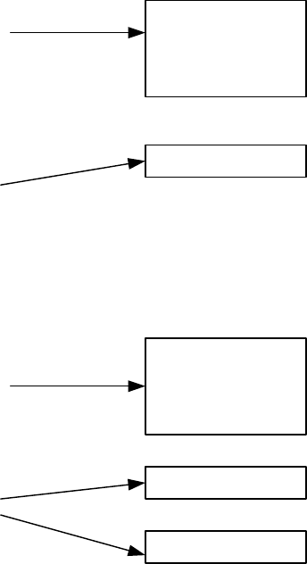
Page 1–25
18 September 2007
SYSTEM DESCRIPTION, INSTALLATION, AND MAINTENANCE MANUAL
eNfusion™ HSD-128 High-speed Data Terminal
The 24-bit Forward ID strap pins, available on the ARINC 600 connector, form
part of the Inmarsat serial number (ISN). The ISN consists of the type approval
number and the Fwd ID address. Each Forward ID is associated with Inmarsat
Mobile Numbers (IMN), which are the numbers that a user would dial from the
ground to reach the terminal on an aircraft. There is a unique IMN for each of
the service types (e.g. Swift64 ISDN 64 kbps data).
When strapping the Forward ID on the HSD-128, the first number in the Forward
ID pair is used. The HSD-128 internally identifies the second Forward ID by
looking up a table in its memory. It is important to strap the first number; otherwise,
the HSD-128 will not be able to correctly look up the second number.
For strapping the Forward ID on the HSD-X in a four-channel configuration,
although each HSD-X can use either number in the second pair, typically the first
number of the second pair is assigned to the first HSD-X and the second number
of the second pair to the second HSD-X. Figure 1–1 illustrates the assignment
of Forward IDs in a 3-channel system. Figure 1–2 illustrates the assignment of
Forward IDs in a 4-channel system.
Note: The placeholder for the Forward ID in the following illustrations uses
“xxxxxx” to represent the six-digit hex number of a valid Forward ID.
Uppercase “X’s” indicate a strapped Forward ID address.
Figure 1–1. Forward ID Assignment (3-channel system)
Figure 1–2. Forward ID Assignment (4-channel system)
XXXXXX
xxxxxx
XXXXXX
xxxxxx
HSD-128
HSD-X 1
First Forward ID pair
(one for each channel card)
Second Forward ID pair
(Second Forward ID of pair is
not used)
XXXXXX
xxxxxx
XXXXXX
XXXXXX
HSD-128
HSD-X 1
HSD-X 2
First Forward ID pair
(one for each channel card)
Second Forward ID pair
(one for each HSD-X)
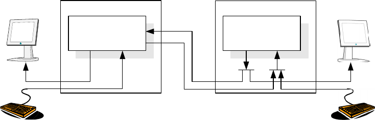
Page 1–26
18 September 2007
SYSTEM DESCRIPTION, INSTALLATION, AND MAINTENANCE MANUAL
eNfusion™ HSD-128 High-speed Data Terminal
(d) RS-232 Maintenance Port
Like the HSD-128, HSD-X units have an RS-232 Maintenance Port interface that
provides access to a maintenance utility program for system monitoring and
testing purposes.
Access to the maintenance port and the HSD Maintenance Utility Program is
possible using an RS-232, VT-100 terminal (PC or Laptop operating a terminal
emulation program such as HyperTerminal).
For testing and monitoring of all components of the Multi-Channel HSD
configuration, access to all units in the system is achieved using a single terminal
(PC or Laptop) connected to the Maintenance Port of the HSD-128 Transceiver.
Communication with any installed HSD-Xs installed in the system is possible by
either passing through the HSD’s Maintenance Facility when operating in
“console-mode” or through a direct connection to individual HSD-X units. Figure
1–3 illustrates the Maintenance Port Facility in a Multi-Channel configuration.
Note: For information on the operation of the HSD Maintenance Utility Program
in “Console-Mode” refer to "Test and Fault Isolation" on page 4-1.
Although system monitoring is possible using the “console-mode” feature,
software updates, if required, must be loaded directly to the HSD-128 and each
HSD-X via their respective maintenance port.
Direct connection to the front-panel of the HSD-X maintenance port requires an
HSD-X maintenance port cable. The front connector, maintenance port supports
trace and data load functions and is a female, micro-D-type, M83513/04-B11N,
or equivalent. As well, a permanent connector wired to the rear, middle-plug,
maintenance port connector can be installed for remote access. A detailed
description of the HSD-X maintenance port pins is provided in "Test and Fault
Isolation" on page 4-1. The RS-232 connection settings for the HSD-X
maintenance port are the same as for the HSD-128 as listed below:
• Baud rate – 19.2 kbps
• Data bits – 8
• Stop bits – 1
• Parity – none
• Flow control – none
Figure 1–3. Maintenance Port Access
Maintenance
Facility
HSD-128
Maintenance
Facility
HSD-X
Pass-
through
out inout in
ARINC 429
Slave Chain
RS232 RS232

Page 1–27
18 September 2007
SYSTEM DESCRIPTION, INSTALLATION, AND MAINTENANCE MANUAL
eNfusion™ HSD-128 High-speed Data Terminal
(e) HSD-X Remote Status Panel (Optional)
The outputs to the optional “Remote Status Panel” provide a visual indication of
the operational status of the HSD-X. They “mirror” the unit’s front panel LEDs
labeled as Power (LED1), Fault (LED2), and Channel Available (LED3). Tabl e
1–20 defines the interpretation for each LED. Refer to "Installation" on page 3-1
for detailed installation and circuit requirements.
(f) HSD-X Fault Conditions
A failure in the HSD-X may be because of a number of fault conditions. Upon
detection of a fault condition, the HSD-X activates its red, Fault LED. The
potential fault conditions are:
• HSD/HSD-X communications link fault
• Channel Card fault
• Data I/O fault
• Internal ROM fault
• Internal RAM fault
• Over Temperature fault
G. User Interfaces
The HSD can support multiple voice and data communication configurations depending
on the number of channel cards the unit contains and the mode of installation.
The most likely user configurations include a networking device (such as a router or a file
server) that allows multiple users to share the channel capability offered by the HSD
(single, dual, or multiple channels depending on model, mode, and configuration of the
HSD or HSD-X transceivers installed).
The selected networking device must have the capability to decide which combination of
services is required at any particular moment and activate it accordingly. Therefore,
simultaneous RS-232 and BRI S/T connections are required.
A different way to achieve this functionality is to use the 10BASE-T port to carry a PPP
over Ethernet virtual connection between the networking device (typically a file server)
and the HSD. Support for PPP over Ethernet is also required on the user’s side.
Note: HSD transceivers PN 1110-A-0150 and 1110-A-0160 have Data I/O Type 2 Cards
installed and support the Ethernet interface. All other HSD transceivers must have
service bulletin, 1110-SB-0004 accomplished to support the Ethernet interface. All
HSD-X transceivers support an Ethernet interface.
Table 1–20. HSD-X Front Panel LEDs Output Designations
LED Name LED Color Indication Description
Top (LED1) Power GREEN Power (ac); Flashes at 1 Hz rate while
“in call”
Middle (LED2) HSD-X Fail RED Fault (Illuminates upon HSD-X failure)
Bottom (LED3) Channel
Available
GREEN Channel Available
Page 1–28
18 September 2007
SYSTEM DESCRIPTION, INSTALLATION, AND MAINTENANCE MANUAL
eNfusion™ HSD-128 High-speed Data Terminal
Figure 1–4 and Figure 1–5 illustrate the user interfaces for single-channel HSD
transceiversFigure 1–6 and Figure 1–7 illustrate the user interfaces for dual-channel HSD
transceivers. For clarity, these figures only display Data Services. Voice devices are
supported by direct connection to the HSD using EURO ISDN telephones or by indirect
connection to a router or terminal adapter using two-wire telephone handsets.
(1) Stand-Alone Mode User Interfaces
Dual-channel HSD transceivers support a maximum of two simultaneous instances
of Swift64 Mobile ISDN and/or Mobile Packet Data Services (MPDS) services.
(2) Collins Cooperative Mode User Interfaces
In Cooperative Mode installations, the HSD system provides one channel of Swift64
data service and Aero H/H+ call capability. Swift64 and Aero H/H+ calls are
simultaneously possible providing the following system conditions are met:
• If a Swift64 call is in process and an Aero H/H+ call is attempted, either incoming
or outgoing, the Aero H/H+ call is allowed to proceed providing that there is
sufficient HPA power available to process all calls.
• If any Aero H/H+ calls are in process, a Swift64 call is allowed providing that there
is sufficient HPA power available to process both the Swift64 and Aero H/H+ calls.
(3) Honeywell Combined Mode User Interfaces
In single-channel transceivers in Combined Mode installations, the HSD system
provides one channel of Swift64 data service and Aero H/H+ call capability. In
dual-channel transceivers in Combined Mode installations, the HSD system provides
two channels of Swift64 data service and Aero H/H+ call capability. Swift64 and Aero
H/H+ calls are simultaneously possible providing the following system conditions are
met:
• If a Swift64 call is in process and an Aero H/H+ call is attempted, either incoming
or outgoing, the Aero H/H+ call is allowed to proceed providing that there is
sufficient HPA power available to process all calls.
• If any Aero H/H+ calls are in process, a Swift64 call is allowed providing that there
is sufficient HPA power available to process both the Swift64 and Aero H/H+ calls.
• If both call types are in process, and system resources become limited due to
dropping antenna gain, then Aero H/H+ calls will maintain priority.
(4) Selective Mode User Interfaces
In Selective Mode operation, dual-channel HSD transceivers support a maximum of
two simultaneous instances of Swift64 Mobile ISDN and/or MPDS services.
(5) Multi-Channel Configurations
The HSD Multi-Channel configuration combines a dual-channel, Stand-Alone Mode
HSD-128 Transceiver with one or more single-channel HSD-X Transceivers to add
additional channels to the system.
MPDS connections demand more power and may reduce channel availability. AMBE
connections demand less power and may increase channel availability.
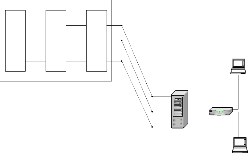
Page 1–29
18 September 2007
SYSTEM DESCRIPTION, INSTALLATION, AND MAINTENANCE MANUAL
eNfusion™ HSD-128 High-speed Data Terminal
Each channel provides an ISDN 64 kbps connection that can be used for voice or
data services. The two channels in the HSD can be internally bonded to provide a
128 kbps ISDN data connection. Externally, all four channels shown in Figure 1–10
can be combined to provide a single 256 kbps capability with the help of a router,
Ethernet hub, or Terminal Adapter.
Although the Multi-Channel HSD configuration is designed to accommodate one
HSD-128 and multiple HSD-Xs, the number of channels that can be active at one time
is dependent on the number of channels available at the Land Earth Station (LES),
the available HPA power, and the available antenna gain—which can vary over the
course of a flight.
At the time of printing, Multi-Channel HSD systems support four, simultaneous,
high-speed data connections—with software automated, staggered initiation of calls
(approximately 20 seconds apart).
Figure 1–4. System Interface Block Diagram Single Channel System
Channel Card
Data I/O Processor
ARINC Connector
HSD Transceiver
ISDN S/T ISDN S/T
RS-232 RS-232
10BT
RS-232
File Server
Laptop computer
Laptop computer
ISDN S/T
10BT
10Base-T
Router
NOTE: Only HSD transceivers PN 1110-A-0150
and 1110-A-0160 or HSD transceivers with
Service Bulletin 1110-SB-0004 accomplished
and HSD-X transceiver extensions support the
Ethernet (10BaseT) interface.
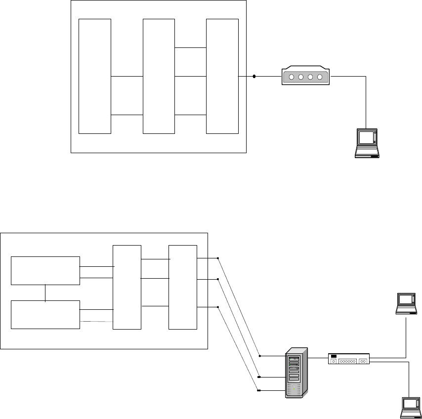
Page 1–30
18 September 2007
SYSTEM DESCRIPTION, INSTALLATION, AND MAINTENANCE MANUAL
eNfusion™ HSD-128 High-speed Data Terminal
Figure 1–5. Reduced Functionality Single-Channel System
Figure 1–6. System Interface Block Diagram Dual-Channel System
Channel Card
Data I/O Processor
ARINC Connector
HSD Transceiver
ISDN S/T ISDN S/T
RS-232 RS-232
10BT
Laptop computer
Serial or
USB
Terminal Adapter
ISDN S/T
HSD Transceiver
RS-232
File Server
Laptop computer
Laptop computer
ISDN S/T
10BT
10Base-T/
USB
Hub
(10BT, USB)
10BT
Data I/O Processor
ARINC Connector
ISDN S/T
ISDN S/T
RS-232 RS-232
10BT
Channel Card
Channel Card
ISDN S/T
RS-232
NOTE: Only HSD transceivers PN 1110-A-0150
and 1110-A-0160 or HSD transceivers with
Service Bulletin 1110-SB-0004 accomplished
and HSD-X transceiver extensions support the
Ethernet (10BaseT) interface.
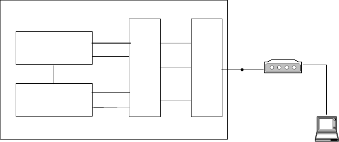
Page 1–31
18 September 2007
SYSTEM DESCRIPTION, INSTALLATION, AND MAINTENANCE MANUAL
eNfusion™ HSD-128 High-speed Data Terminal
Figure 1–7. Reduced Functionality Dual-Channel System
(6) ISDN Circuit-Switched Data Interface
HSD and HSD-X transceivers connect to a variety of interface options. The physical
interface for ISDN service is EURO S/T, which supports several types of connections
to user equipment.
HSD and HSD-X transceivers provide either one or two ISDN S/T bus interfaces
(depending on the number of channel cards and mode of installation of the unit).
Each bus is capable of hosting up to eight, EURO ISDN physical devices—which
means a one-channel system supports up to eight physical connections to EURO
ISDN devices; a two-channel system supports up to sixteen physical connections to
EURO ISDN devices.
Each channel card supports communications with one, 64 kbps, ISDN B channel on
an ISDN U interface bus. If the channel(s) is “busy” or “in-call", the request for service
is denied (the system is busy).
For ISDN data devices that support bonding with a two-channel card HSD transceiver,
the device uses both ISDN B channels to increase data throughput as long as no
other devices are “in call.”
For incoming calls, each channel card (ISDN BUS) is assigned a Forward ID. The
Forward ID is assigned Inmarsat Mobile Numbers (IMNs) for each service type. Each
service type has an associated Multiple Subscriber Number (MSN). The MSNs are
configured in the ISDN devices to direct incoming calls of different service types to
the appropriate device.
For a two-channel HSD transceiver, two IMNs are assigned for each service type.
"System Operation" on page 2-1 provides examples and a detailed description of the
routing assignments for the HSD transceiver.
Several ISDN interface options are shown in Figure 1–8. The physical interface is
EURO S/T, which can support up to eight simultaneous connections to user
equipment. In the illustrated example, the ISDN port is only used for circuit-switched
services (Swift64 Mobile ISDN).
Data I/O Processor
ARINC Connector
HSD Transceiver
ISDN S/T ISDN S/T
RS-232
RS-232
10BT
Laptop computer
Serial or
USB
Channel Card
Channel Card
ISDN S/T
RS-232
Terminal Adapter
ISDN S/T
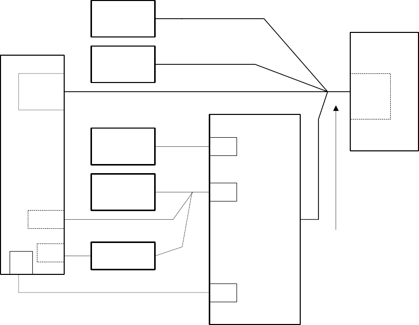
Page 1–32
18 September 2007
SYSTEM DESCRIPTION, INSTALLATION, AND MAINTENANCE MANUAL
eNfusion™ HSD-128 High-speed Data Terminal
Note: Activating MPDS on a particular channel card temporarily, disables the ISDN
port on that channel card while MPDS service is in-use.
For connection to Inmarsat Mobile ISDN services, install an RJ-45 interface connector
in the cabin area. "Installation" on page 3-1 describes the RJ45 connector and cable
termination.
Figure 1–8. ISDN Connection Options
(7) RS-232 Interface
The simplest configuration, using the RS-232 interface, allows users to connect
directly to the HSD without any kind of networking device (i.e. router or file server).
The port identified as DTE-MPDS, on the Interconnect Drawings (refer to "Installation"
on page 3-1), is a serial data port capable of operating up to 115 kbps line speed with
a maximum throughput of 64 kbps. This RS-232 port only supports Mobile Packet
Data Service (MPDS).
Install a 9-pin, socket D-Sub interface connector in the cabin area for connection
to this service. Configure the connection as:
• Bits per second – 115200
• Data bits – 8
LAPTOP
(PC)
FAX
(ISDN)
PHONE
(ISDN)
ISDN
BRI S/T
RJ-11
RJ-11
RS232
EURO T/A
(ISDN)
Modem
PCMCIA
CARD
(ISDN)
HSD
Transceiver
COM EXT. MODEM
(ANALOG)
FAX
(TIP/RING)
PHONE
(TIP/RING)
COM
64K UDI DATA
(MSN 10, 11, 12)
64K
SPEECH
(MSN 40)
3.1K AUDIO
(MSN 20)
Note: Although several ISDN
DTE devices may be
connected to an ISDN S/T
Bus, the HSD only supports
one ISDN call at one time
per channel card.
One ISDN S/T Bus per
HSD Transceiver
Channel Card
Page 1–33
18 September 2007
SYSTEM DESCRIPTION, INSTALLATION, AND MAINTENANCE MANUAL
eNfusion™ HSD-128 High-speed Data Terminal
• Parity – none
• Stop bits – 1
• Flow control – Hardware
Refer to the applicable Interconnect Diagrams provided in "Installation" on page
3-1 for complete pinout designations.
(8) Ethernet Data Interface
HSD transceivers PN 1110-A-0150 and 1110-A-0160 support the Ethernet interface.
All other HSD transceivers require the accomplishment of service bulletin,
1110-SB-0004 to upgrade to a Data I/O Card Type 2 that supports the Ethernet
interface.
The Ethernet port provides a 10 Mb/s access, with a 10BASE-T physical interface.
The HSD Data I/O Controller takes the PPP data stream and directs it to the required
port on the channel card, depending on the type of service selected by the user. PPP
over Ethernet protocol (PPPoE) is required on the user equipment to allow the
establishment of virtual connections to either service. Use the Ethernet port for either
Swift64 Mobile ISDN or MPDS service.
(9) ISDN S/T Interface
Transceivers with a Data I/O Type 1 card installed support eight simultaneous
connections to user equipment in single-channel card system and sixteen
simultaneous connections in two-channel systems.
HSD models 1110-A-0150 and 1110-A-0160 and HSD Transceivers with service
bulletin 1110-SB-0004 accomplished have a Data I/O Type 2 card installed. Data I/O
Type 2 cards support seven simultaneous connections to user equipment in
single-channel card system and fifteen simultaneous connections in two-channel
systems.
Note: An HSD transceiver with a Data I/O Card Type 2 uses one S/T Bus “device
connection” for system use.
Install an RJ-45 interface connector in the cabin area to facilitate connection to the
Ethernet interface. Refer to "Installation" on page 3-1 for a description of the RJ-45
connector and cable termination.
(10)Maintenance Port Interface
The HSD is equipped with a maintenance port, located on the front panel of the HSD
transceiver with remote access also available through the rear ARINC 600 connector.
The maintenance port provides the physical connection to a password-protected,
HSD maintenance utility program that provides a system interface for users or service
personnel who need to upgrade, monitor, or troubleshoot the system.
The user connects to the Maintenance Port either through the Maintenance 25-pin
socket D-Sub (DB25S) connector on the front panel of the HSD, or through a remote
9-pin socket D-Sub (DB9S) connector via the ARINC 600 connector, as described in
"Test and Fault Isolation" on page 4-1.
Page 1–34
18 September 2007
SYSTEM DESCRIPTION, INSTALLATION, AND MAINTENANCE MANUAL
eNfusion™ HSD-128 High-speed Data Terminal
A standard VT100 compatible terminal or computer (PC/laptop) running an emulator
program such as HyperTerminal©, ProComm (PCPLUS)©, or another serial
communication package provides the user interface to the HSD maintenance utility
program. Configure the connection as follows:
• Bits per second – 19200
• Data bits – 8
• Parity – none
• Stop bits – 1
• Flow control – none
The HSD supports two different end user access levels within the Maintenance Port
architecture: End User or Field Representative.
(a) End User Access: Level 1
Password: menu
This limited-access level is for anyone without technical training on the product.
It provides read-only access to help users diagnose problems with the assistance
of product support personnel.
(b) Field Representative Access: Level 2
Password: maint
This level is for trained original equipment manufacturer (O.E.M.) installers and
product support personnel. This access level supports “read’” and limited “write”
capabilities. Users are able to disable/mask/clear faults, change satellite or LES
preferences, view and modify certain EEPROM parameters, and perform other
maintenance or upgrade functions.
"Test and Fault Isolation" on page 4-1 provides a detailed description of the two
levels of user access and of the menus, report selections, functionality, and
system diagnostic procedures of the HSD Maintenance Utility Program.
H. Initiated-Self-Test
The Initiated-Self-Test occurs during the power up sequence or when the “TEST” button
(located on the front panel of the unit) is depressed and held down for three seconds or
more. It provides the same functionality as the remote reset switch.
I. Owner Requirements Table
An Owner Requirements Table Tool (ORT Tool) is a Windows-based program that is used
to create and change system configuration disks for HSD transceivers. The configuration
data files created using the ORT Tool are loaded into the HSD transceiver via the RS-232
Maintenance Port interface.
Detailed information on how to use the ORT Tool is provided in "Test and Fault Isolation"
on page 4-1.
Page 1–35
18 September 2007
SYSTEM DESCRIPTION, INSTALLATION, AND MAINTENANCE MANUAL
eNfusion™ HSD-128 High-speed Data Terminal
4. Inmarsat System Overview
A. General
This section provides an overview of the Inmarsat satellite communications system and
networks.
B. Satellite Network Overview
The satellite communication system (SATCOM) comprises global satellite networks, Land
Earth Stations (LES), and Mobile Earth Stations (MES).
Satellite communication systems provide users with long-range voice and data
communication by accessing global satellite and ground communications networks.
Inmarsat is an international organization that operates and maintains the satellites and
satellite networks. Inmarsat operates multiple geostationary satellites. Each satellite is
located over an oceanic region; the current ocean region names are:
• Atlantic Ocean Region-East (AOR-E)
• Atlantic Ocean Region-West (AOR-W)
• Indian Ocean Region (IOR)
• Pacific Ocean Region (POR)
These satellites provide worldwide telecommunication services for aviation, shipping, and
land-mobile terminal users. The satellites connect to ground telecommunication systems
through the LES.
The HSD transceiver, in conjunction with an ARINC 741 Aero H/H+ antenna subsystem,
acts as an MES. The combined system provides users with a data and voice
communications link to the satellite network and global telecommunications system.
Figure 1–9 illustrates a simplified satellite communications system.
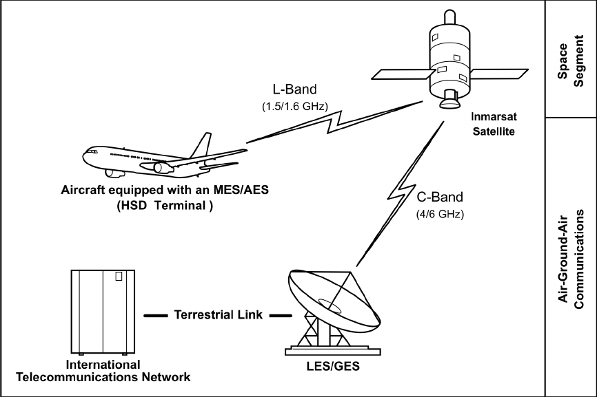
Page 1–36
18 September 2007
SYSTEM DESCRIPTION, INSTALLATION, AND MAINTENANCE MANUAL
eNfusion™ HSD-128 High-speed Data Terminal
Figure 1–9. Simplified Aeronautical Satellite Communications System
Page 1–37
18 September 2007
SYSTEM DESCRIPTION, INSTALLATION, AND MAINTENANCE MANUAL
eNfusion™ HSD-128 High-speed Data Terminal
5. HSD Modes and Configuration Descriptions
A. General
This section describes the system mode and configuration variations for the HSD
High-Speed-Data SATCOM Transceiver installations.
B. Overview
HSD transceivers install in a variety of customized configuration modes. HSD transceivers
may be installed as Stand-Alone systems or as Non-Stand-Alone units installed within
existing SATCOM systems. Four different system configuration modes are possible:
• Stand-Alone Mode—single or dual channel transceiver
• Cooperative Mode—single channel transceiver (with Collins SAT-906 systems)
• Combined Mode—single or dual channel transceiver (with Honeywell MCS systems)
• Selective Mode—single or dual channel transceiver (with Collins SAT-906 or
Honeywell MCS systems)
• Multi-Channel configurations—dual-channel HSD transceiver integrated with
additional HSD-X extension transceiver(s) to support multi-channel operation (more
than two 64 kbps channels).
(1) Channel Card Configurations
This section describes the types of channel card configurations supported by HSD
transceivers.
(a) Dual-Channel Card HSD Transceivers
In dual-channel card HSD transceivers, both 64 kbps channels work either
independently or as a bonded 128 kbps data-link to the Inmarsat
Communications Network.
The user has the option to select the service type needed—either circuit-switched
data (Swift64 Mobile ISDN) or MPDS. The HSD also supports two simultaneous
voice or 14.4 kbps fax calls when not being used in data mode.
(b) Single-Channel Card HSD Transceivers
Single-channel-card HSD transceivers provide one 64 kbps channel that
supports a bi-directional, 64 kbps data-link to the Inmarsat Communications
Network.
The user has the option to select the service type needed—either Swift64 Mobile
ISDN or MPDS. The HSD also supports one voice or 14.4 kbps fax call when not
being used in data mode.
(c) Multi-Channel Configurations
Stand-Alone HSD-128 transceivers in Multi-Channel installations support two 64
kbps channels that work either independently or as a bonded 128 kbps data-link
to the Inmarsat Communications Network as well as an additional 64 kbps
channel per HSD-X installed in the system.
Page 1–38
18 September 2007
SYSTEM DESCRIPTION, INSTALLATION, AND MAINTENANCE MANUAL
eNfusion™ HSD-128 High-speed Data Terminal
The user has the option to select the service type needed—either circuit-switched
data (Swift64 Mobile ISDN) or MPDS. The HSD also supports three or more
simultaneous voice or 14.4 kbps fax calls when not being used in data mode—
depending on the number of additional HSD-X transceivers installed.
(2) Installation Modes and Configurations
(a) Stand-Alone Mode Systems
In Stand-Alone Mode, the HSD transceiver controls both the HPA and antenna.
The system supports one channel of Swift64 Mobile ISDN and one channel of
Swift64 MPDS or two channels of Swift64 Mobile ISDN or two channels of MPDS.
For details, refer to the system block diagram.
(b) Non-Stand-Alone Mode Systems
In Non-Stand-Alone configuration modes, the HSD hardware acts as the High
Gain Antenna HPA for Aero H/H+ calls and provides one or two channels of
Swift64 communications. In these configurations, the Aero H/H+ system provides
the system interface to the aircraft antenna subsystem. The radio frequency (RF)
from the HSD transceiver and the Aero H/H+ system is combined in the HSD.
The receive RF from the antenna sub-system is split before being presented to
the Aero H/H+ and HSD transceivers.
1. Cooperative Mode Systems
HSD transceivers installed in Cooperative Mode configurations operate with
a SAT-906 SATCOM system. The HSD hardware is installed in the SAT-906
HPA equipment position. A communications link between the SAT-906
system and the HSD transceiver coordinates the use of the HPA.
An external splitter “splits” the antenna RF receive (Rx) signal path to both
the HSD and the SAT-906 SATCOM systems. The antenna is controlled by
the SAT-906 system’s SDU.
This system configuration provides one channel of Swift64 Mobile ISDN,
MPDS high-speed data, or Aero H/H+ communications. Simultaneous
Swift64 and Aero H/H+ calls are possible. Swift64 HSD calls proceed even if
an Aero H/H+ incoming or outgoing call is in progress providing there is
sufficient HPA power available to process all of the calls.
To use ARINC 429 data from the Collins SAT-906 SDU, the minimum
requirement for HSD control-card software is version 4.5 (or later). Version
4.5 control-card software is available via HSD service bulletins:
1110-SB-0001 and 1110-SB-0003. The recommended software version for
optimum system performance is version 7.5 or later. Version 7.5 is available
via service bulletin, 1110-SB-0015.
The SAT-906 SDU must have core software –068, including service bulletins
31 and 501, which change the unit to a –150 designation and include wiring
SDU pin TP12E grounded to indicate that the SDU is operating with an HSD.
To achieve the current “best system” operation performance, incorporate
EMS SATCOM service bulletin 1110-SB-0015. At the time of writing,
Cooperative Mode installations only support single-channel card
configurations. If installing a dual-channel HSD-128 transceiver in a
Cooperative Mode environment, the HSD EEPROM parameters must be

Page 1–39
18 September 2007
SYSTEM DESCRIPTION, INSTALLATION, AND MAINTENANCE MANUAL
eNfusion™ HSD-128 High-speed Data Terminal
configured as a single-channel system. Use the HSD maintenance utility
program to configure the EEPROM settings for a single channel card. (Menu
3, press M, select miscellaneous parameter number 10.)
Refer to the system block diagram in Figure 1–12 for Cooperative Mode
system details.
2. Honeywell Combined Mode (HCM) Systems
HSD transceivers installed in Combined Mode configurations operate with
the Honeywell Aero H/H+ MCS 3000/6000 and MCS 4000/7000
Multi-Channel Satellite Communication Systems. The HSD hardware is
installed in the SATCOM HPA equipment position, replacing the Honeywell
HPA.
An external splitter “splits” the antenna RF receive (Rx) path signal to the
HSD and the Aero H/H+ systems. The antenna is controlled by the Aero H/H+
system’s SDU.
This system configuration provides up to two channels of access to
high-speed Swift64 Mobile ISDN or MPDS services as well as the existing
Aero H/H+ communications simultaneously. Swift64 HSD calls proceed even
if an Aero H/H+ incoming or outgoing call is in progress—providing there is
sufficient HPA power available to process all of the calls.
In Combined Mode (HCM) installations, the HSD system provides two
channels of Swift64 data service and Aero H/H+ call capability. Swift64 and
Aero H/H+ calls are possible simultaneously under the following conditions:
• If a Swift64 call is in process and an Aero H/H+ call is initiated, either
incoming or outgoing, the Aero H/H+ call is allowed to proceed;
• If any Aero H/H+ calls are in process, a Swift64 call is allowed to proceed
providing that there is sufficient HPA power available to process both the
Swift64 and Aero H/H+ calls; and,
• If both call types are in process, and system resources become limited
due to dropping antenna gain, Aero H/H+ calls will maintain priority.
Refer to the system block diagram in Figure 1–13 for details.
3. Selective Mode Systems
HSD transceivers installed in Selective Mode configurations operate with an
Aero H/H+ system. The HSD transceiver is installed in the Aero H/H+ HPA
equipment position.
This system configuration provides either one or two channels of Swift64
Mobile ISDN and MPDS high-speed-data communications OR Aero H/H+
communications. Simultaneous Swift64 and Aero H/H+ calls are not possible.
Swift64 HSD calls are terminated if an Aero H/H+ incoming or outgoing call
is detected by the HSD transceiver allowing the Aero H/H+ call to proceed.
While Aero H/H+ calls are in process, Swift64 HSD calls cannot be initiated.
Refer to the system block diagram in Figure 1–13 for details.
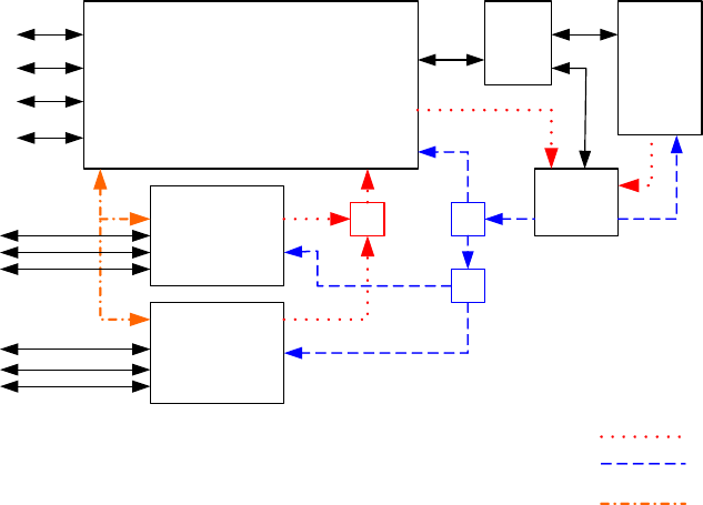
Page 1–40
18 September 2007
SYSTEM DESCRIPTION, INSTALLATION, AND MAINTENANCE MANUAL
eNfusion™ HSD-128 High-speed Data Terminal
(c) Multi-Channel Configurations
The HSD Multi-Channel configuration combines a dual-channel, Stand-Alone
Mode HSD-128 Transceiver with one or more single-channel HSD-X
transceivers to add additional channels to the system.
Each channel provides an ISDN 64 kbps connection that can be used for voice
or data services. The two channels in the HSD can be internally bonded to
provide a 128 kbps ISDN data connection. Externally, all four channels shown
in Figure 1–10 can be combined to provide a single 256 kbps capability with the
help of a router, Ethernet hub, or Terminal Adapter.
The HSD-128 is the master of the system, and as its name suggests, it controls
the overall operation of the Multi-Channel HSD configuration. It keeps track of
time and allocated power and may command the HSD-X “slaves” to terminate
calls under certain conditions, such as an ocean region change. The HSD-X
transceivers are wired to the HSD-128 HPA and therefore compete equally for
HPA power allocation.
The transmit signal of each channel is fed through a combiners/attenuator
combination to the HPA located in the HSD and ultimately to the antenna.
Conversely, the receive signal from the antenna goes through a series of splitters
on its way to each channel.
On power-up, HSD-X transceivers go through an initialization process that
identifies and communicates the number of extension channels and their position
in the system chain back to the HSD-128 controller.
The block diagram in Figure 1–10 illustrates the system function of the HSD-128,
two HSD-Xs, and the antenna system.
Figure 1–10. Multi-Channel System Block Diagram
HSD-128 (Master)
HSD-X
(Slave)
HSD-X
(Slave)
?\
HGA
D/LNA
ACU
\
ISDN
Transmit Path
Receive Path
Crosstalk Bus
ISDN
MPDS (RS232)
Ethernet (10Base T)
(Optional)
ISDN
ISDN
MPDS (RS232)
MPDS (RS232)
Ethernet (10Base T)
Ethernet (10Base T)
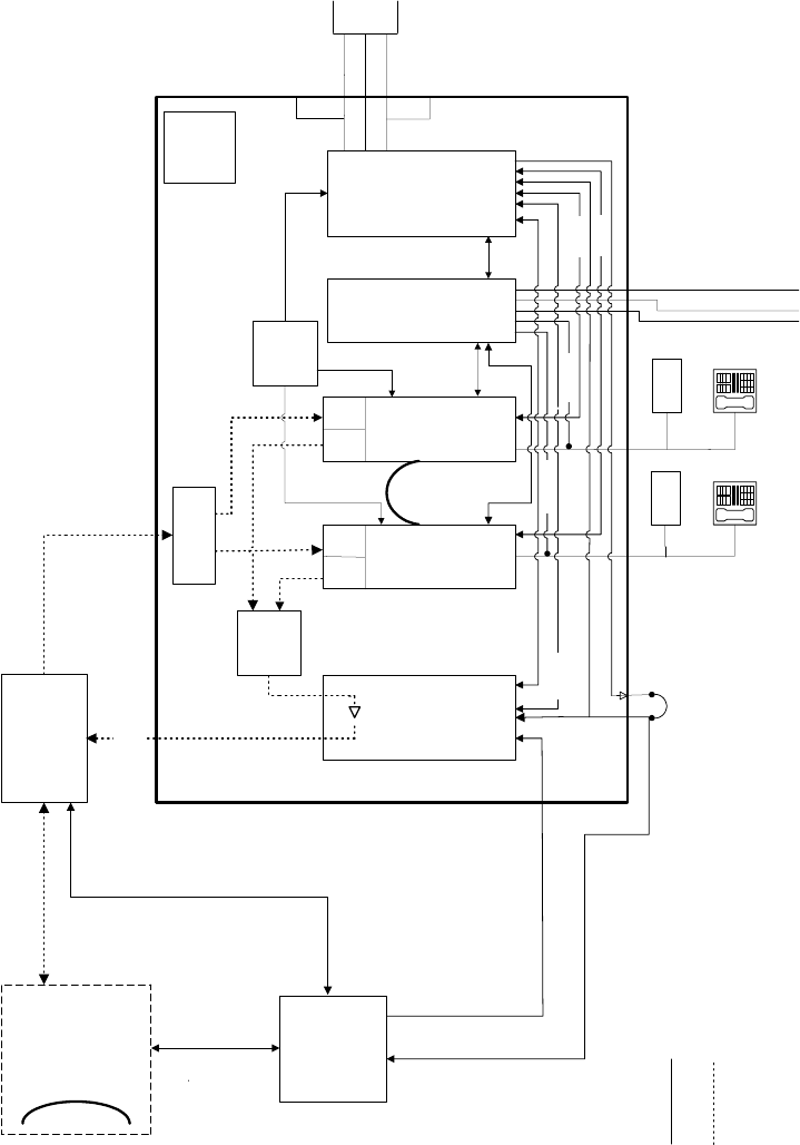
Page 1–41
18 September 2007
SYSTEM DESCRIPTION, INSTALLATION, AND MAINTENANCE MANUAL
eNfusion™ HSD-128 High-speed Data Terminal
Figure 1–11. Stand-Alone Mode System Block Diagram
HPA
(60W)
Channel
Card 2
Channel
Card 1 Data I/O
Card
Control Card
D/LNA
ACU
Terminal
Adapter
Combiner
ARINC 741
Antenna
Splitter
ISDN TelephoneISDN Telephone
TX RX RXTX
Oscillator
10 Mhz
Front Panel DB25S
LEDs
Reset
Maintenance Port
Multi-Control IN
RS232 MPDS (2)
ISDN (2)
ISDN (1)
Tx/Rx
Bond
(RS422)
RS232
MPDS
65 dB Gain
Power/Control &
BITE
Multi-Control
Power
Supply
28 V dc or
115 V ac,
400 Hz
Terminal
Adapter
Signals
RF
MPDS
ACU BITE/HPA Mute
STAND-ALONE SYSTEM (1 or 2 CHANNEL)
LEGEND
10 Base-T
(
Future
)
Power/Control &
BITE
RX
Front Panel LEDs
Remotes
TX
OCXO Ready
RS232
Multi-Control OUT
RS232
RS232 MPDS (1)
ARINC 429
RS232
ISDN (1)
ISDN (2)
HSD TRANSCEIVER
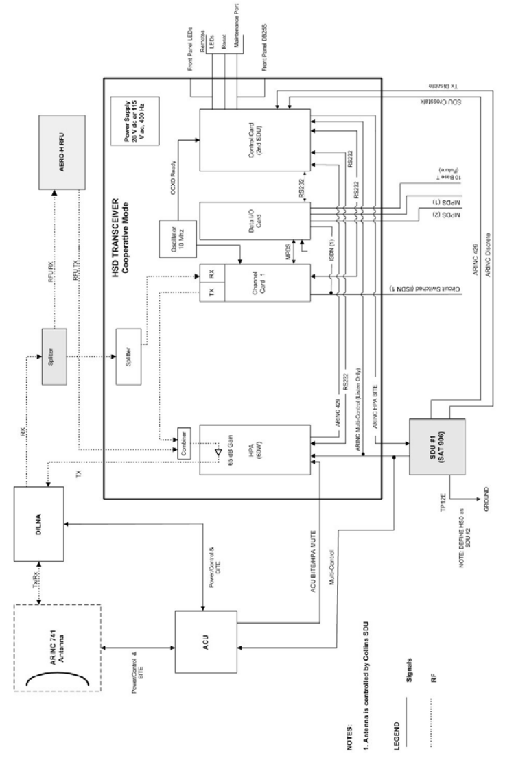
Page 1–42
18 September 2007
SYSTEM DESCRIPTION, INSTALLATION, AND MAINTENANCE MANUAL
eNfusion™ HSD-128 High-speed Data Terminal
Figure 1–12. Cooperative Mode System Block Diagram
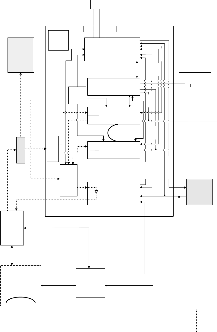
Page 1–43
18 September 2007
SYSTEM DESCRIPTION, INSTALLATION, AND MAINTENANCE MANUAL
eNfusion™ HSD-128 High-speed Data Terminal
Figure 1–13. Combined/Selective Mode System Block Diagram
HPA
(60W)
Channel
Card 2 Channel
Card 1
Data I/O
Card
Control Card
D/LNA
ACU
SDU
ARINC 741
Antenna
Splitter
Splitter
TX RX RXTX
RFU RX
RFU TX
Oscillator
10 Mhz
Front Panel DB25S
LEDs
Reset
Maintenance Port
MPDS (1)
Circuit Switched (ISDN 2)
Circuit Switched (ISDN 1)
RX
TX
Tx/Rx
Bond
(RS422)
RS232
MPDS
65 dB Gain
NOTES:
1. Antenna is controlled by Honeywell SDU
Multi-Control
Power
Supply
28 V dc or
115 V ac,
400 Hz
AERO-H RFU
ACU BITE/HPA MUTE MPDS
OCXO Ready
Signals
RF
LEGEND
Power/Control
& BITE
Power/Control
& BITE
Front Panel LEDs
10 Base T
(Future)
RF Module
RS232
Remotes
MPDS (2)
ARINC HPA BITE
ISDN (1)
ISDN (2)
ARINC Multi-Control (Listen Only) RS232
RS232
RS232
ARINC 429
HSD TRANSCEIVER
COMBINED MODE
Page 1–44
18 September 2007
SYSTEM DESCRIPTION, INSTALLATION, AND MAINTENANCE MANUAL
eNfusion™ HSD-128 High-speed Data Terminal
C. Functional System Theory
The HSD is a high-speed SATCOM Transceiver that contains: either one or two channel
cards, a high stability reference oscillator, a high power amplifier, a data processor module,
and a power supply. The HSD receives power from the aircraft as either 28 V dc or 115
V ac, 400 Hz.
When integrated with the SAT-906 Aero H/H+ as a Cooperative Mode system (refer to
Figure 1–12), the HSD L-band Rx/Tx interfaces are shared with those of the SAT-906 via
combiners/splitters between the DLNA and the HPA. The SDU of the SAT-906 maintains
control over the HSD component via the crosstalk bus and associated discretes.
HSD transceivers installed in Combined Mode configurations operate with the Honeywell
Aero H/H+ MCS 3000/6000 and MCS 4000/7000 Multi-Channel Satellite Communication
Systems. The HSD hardware is installed in the SATCOM HPA equipment position,
replacing the existing HPA. An external splitter “splits” the antenna receive (Rx) path to
send the RF signal to the HSD and the Aero H/H+ systems. The antenna is controlled by
the Aero H/H+ system’s SDU.
The HSD supports one or more channels (depending on the model, mode, and
configuration installed) of Inmarsat Swift64 MPDS and Mobile ISDN 64 kbps data links.
The HSD and HSD-X both have three different ports that support the following interfaces:
EURO ISDN S/T, serial (RS-232), and Ethernet (10BASE-T). Although able to support
multiple configurations depending on user needs, the following constraints apply:
• EURO ISDN S/T port supports Swift64 Mobile ISDN (circuit-switched
services - SCPC) only
• RS-232 port supports MPDS only
• 10BASE-T port supports Swift64 Mobile ISDN or MPDS (Available on HSD
transceivers PN 1110-A-0150 and 1110-A-0160 or HSD transceivers that have
accomplished Service Bulletin, 1110-SB-0004 to upgrade to a Data I/O Type 2 Card)
Note: Only one service type can be used at one time—per HSD or HSD-X transceiver
channel card.
The most likely configurations (as illustrated in Figure 1–14) include connecting a
networking device such as a router or a file server to allow multiple users to share the
channel(s) provided by the HSD.
The simplest configurations, using the RS-232 interface, allow users to connect directly
to the HSD without any kind of networking device (e.g. router or server). The RS-232 port
allows a single user for MPDS only, while the ISDN S/T port will allow up to eight users
on a first come first serve basis.
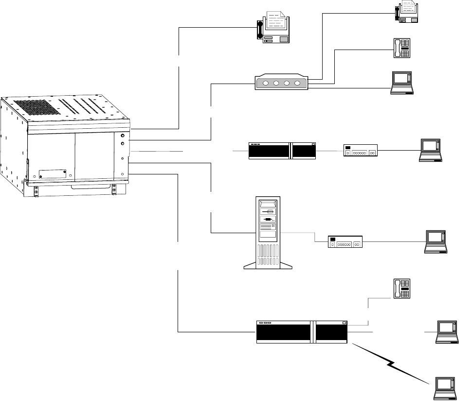
Page 1–45
18 September 2007
SYSTEM DESCRIPTION, INSTALLATION, AND MAINTENANCE MANUAL
eNfusion™ HSD-128 High-speed Data Terminal
Figure 1–14. HSD User Configurations
Hub
(10BT, USB)
10BT 10BT / USB
Server
Fax (Group 4)
Telephone
2 Wire
Laptop computer
TA
RS-232
Laptop computer
EMS CNX Network Module
(EMS PN 1110-A-0501-01, Future Availability)
10BT
Laptop computer
Hub
(10BT, USB)
10BT / USB
Router
ISDN BRI S/T
ISDN BRI S/T
RS-232, ISDN BRI S/T,
or Ethernet 10Base T
(with Data I/O Type 2)
RS-232 or
ISDN BRI S/T
RS-232 or
ISDN BRI S/T
Telephone
Laptop computer
Laptop computer
2 Wire
10-100 Base T
Fax (Group 3)
2 Wire
Page 1–46
18 September 2007
SYSTEM DESCRIPTION, INSTALLATION, AND MAINTENANCE MANUAL
eNfusion™ HSD-128 High-speed Data Terminal
Blank Page
Page 2–1
18 September 2007
SYSTEM DESCRIPTION, INSTALLATION, AND MAINTENANCE MANUAL
eNfusion™ HSD-128 High-speed Data Terminal
SYSTEM OPERATION
1. Introduction
This section provides basic information on registering, commissioning, and operating the HSD
High-Speed Data SATCOM transceiver and HSD-X High-Speed SATCOM Extension
transceiver. For more information on Swift64 service providers and the activation of HSD and
HSD-X transceivers, visit the EMS Technologies HSD Web page at
www.emssatcom.com/hsd/team.asp.
Page 2–2
18 September 2007
SYSTEM DESCRIPTION, INSTALLATION, AND MAINTENANCE MANUAL
eNfusion™ HSD-128 High-speed Data Terminal
2. Activating HSD Transceivers
To activate an HSD or HSD-X transceiver:
1. Obtain terminal information (Forward Identification Numbers and Terminal Type and
Category information) from EMS Technologies.
2. Register the terminal with an Inmarsat approved service provider and activate an
account.
A. Obtaining Terminal Information
Before installing the HSD or HSD-X transceiver, contact EMS Technologies to obtain
terminal information needed to register and activate the unit with Inmarsat.
EMS SATCOM Customer Care assigns an appropriate Terminal Type number and valid
Forward IDs for the HSD transceiver based on the intended installation configuration
(Stand-Alone or Non-Stand-Alone Mode).
Note: Cooperative, Combined, and Selective Mode installations are Non-Stand-Alone
Mode installations that operate with an Aero H/H+ system. Cooperative and
Combined installations are assigned a Category B terminal type. Please note that
Inmarsat does not support Mini-M Voice (4.8 kbps) service for Category B
terminals. For more information on available services for Category B systems,
contact your Inmarsat Service Provider.
Note: If you are replacing or upgrading a Stand-Alone or Selective Mode system with a
Combined Mode system, you need to de-activate the “old” system’s Forward IDs
and service accounts and “activate” new Forward IDs and service accounts to
Category B frequency allocations. This process may take 24 to 48 hours to
complete. Contact your service provider for more information.
When requesting terminal registration information from EMS SATCOM, please have the
following information available:
• End customer name, including contact information
• Purchase order number
• Tail registration number, aircraft type, and serial number of the aircraft the unit is being
installed on
• Serial Number of HSD or HSD-X transceiver(s)
• Intended installation configuration mode (Stand-Alone, Cooperative, Combined
(HCM), Selective, or Stand-Alone in a Multi-Channel Configuration)
Contact EMS SATCOM Aeronautical Sales and Customer Service at:
Toll-free from Canada and U.S.A. 1.800.600.9759
Outside Canada and U.S.A. 1.613.591.9064
Fax: 1 613.591.8703
Web sites: www.emssatcom.com

Page 2–3
18 September 2007
SYSTEM DESCRIPTION, INSTALLATION, AND MAINTENANCE MANUAL
eNfusion™ HSD-128 High-speed Data Terminal
(1) Swift64 Service Categories
Inmarsat has restricted the frequencies assigned to the HSD system eliminating the
possibility of intermodulation signals occurring, thus avoiding any resulting
interference problems with the GPS band signals.
Inmarsat split the band of frequencies assigned to Swift64 High-Speed Data into two
separate categories: Category A and Category B. Category B frequencies are
restricted to those frequencies that do not overlap with AERO-H frequency allocations.
HSD transceivers in Cooperative and Combined Mode installations must be
registered as Category B systems. HSD transceivers in Stand-Alone and Selective
installations do not require restricted frequency allocations. Register Stand-Alone
HSD transceivers, Multi-Channel, and Selective Mode systems as Category A
systems.
The frequencies assigned to 4.8 kbps Low-Speed Voice (LSV) are not within the
managed Category B frequency range. Therefore, LSV is not a service supported by
Inmarsat in Cooperative and Combined Mode HSD transceivers.
Secure communications in Category B, HSD systems do not have access to Mini-M
service. However, HSD transceivers have both c8400 or c21000 M4 circuit-switched
mode channels, which support secure communication operations.
To ensure the correct Category frequency assignments for HSD systems, different
terminal type numbers are assigned to HSD transceivers based on their intended
installation configuration.
Table 2–1 lists the terminal type, frequency category, and supported service types for
all types of HSD transceivers installations.
Note: Category B, Inmarsat terminals do not support Mini-M Voice (4.8 kbps LSV).
Selective Mode is a non-standard installation and it is not a recommended
mode of operation. Selective Mode has been superseded by Combined Mode
operation for MCS series SATCOM and with Cooperative Mode operation for
Table 2–1. Swift64 Category and Service Matrix
HSD
Installation
Mode
Inmarsat
Frequency
Category
Terminal
Type
64 kbps
speech
3.1
KHz
audio
56
kbps
data
64
kbps
UDI
Mini-M
Voice MPDS
Stand-Alone
and
Multi-Channel
(HSD and
HSD-X)
Category A 76ES03 X X X X X X
Collins
Cooperative
Category B 76ES04 X X X X N/A X
Honeywell
Combined
Category B 76ES05 X X X X N/A X
Selective
Mode (Not
Rec’d)
Category A 76ES03 X X X X X X
Page 2–4
18 September 2007
SYSTEM DESCRIPTION, INSTALLATION, AND MAINTENANCE MANUAL
eNfusion™ HSD-128 High-speed Data Terminal
SAT-906 series SATCOM. It is recommended that all systems operating in
Selective Mode be upgraded to support Combined or Cooperative Mode as
applicable.
B. Selecting a Service Provider
Register the HSD transceiver with an Inmarsat service provider. Contact Inmarsat for an
up-to-date list of Inmarsat Swift64 service providers as follows:
Inmarsat
99 City Road, London
EC1Y 1AX
Tel: +44 20 7728 1000
Fax: +44 20 728 1044
Customer Care
Tel: +44 20 7728 1777
Fax: +44 20 7728 1142
Email: customer_care@inmarsat.com
Web addresses: www.inmarsat.com and www.inmarsat.com/swift64/supp_ser.htm
Note: Although the HSD and HSD-X are Mobile Earth Stations (MES), they are referred
to as Aircraft Earth Stations (AES) on the service-provider registration form.
C. Registering and Activating the HSD and HSD-X Transceivers
Contact your Inmarsat service provider and ask for a “Registration for service activation
of Aircraft Earth Station ” form.
To complete the registration form the following information is needed:
• Customer information (address and contact information)
• Service provider details (obtain from your Inmarsat service provider)
• System and terminal information (system terminal type, manufacturer, model number,
serial number of unit and Inmarsat Serial Number)
• Aircraft information (tail number, fuselage/airframe number, manufacturer and model,
and country of registration
• List of services required (e.g. Swift64 Mobile ISDN)
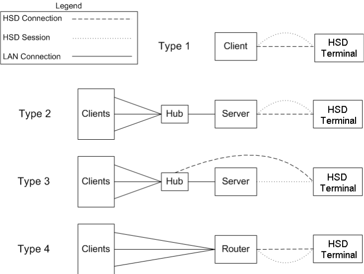
Page 2–5
18 September 2007
SYSTEM DESCRIPTION, INSTALLATION, AND MAINTENANCE MANUAL
eNfusion™ HSD-128 High-speed Data Terminal
3. Configuring HSD Systems
This section provides basic information on how to configure HSD systems for operation with
user devices.
A. Setting up Networks
This section provides basic information on how to configure user connections and
networks for operation with the HSD and HSD-X transceivers and satellite
communications network.
(1) Network Types
The samples in Figure 2–1 have been simplified to illustrate different types of networks
(including a basic, single-user connection). In the illustration, SATCOM refers to HSD
transceivers (including any HSD-X transceivers installed in Multi-Channel
configurations), as well as any associated SATCOM systems in Non-Stand Alone
installations (Cooperative, Honeywell Combined, and Selective Modes).
Figure 2–1. Network Configuration Types
Note: A single client is a server that does not need to share the connection. A server
connecting to a SATCOM through a hub still has the same logical session
link. A router is equivalent to a server and a hub bundled into a single device.
Page 2–6
18 September 2007
SYSTEM DESCRIPTION, INSTALLATION, AND MAINTENANCE MANUAL
eNfusion™ HSD-128 High-speed Data Terminal
(2) Networking Components
The network configurations illustrated in Figure 2–1 have common components that
integrate and operate with HSD transceivers.
• An interface connection to the HSD equipment:
The HSD equipment supports the following interface connections: an RS-232
serial port (MPDS only), a 10BASE-T Ethernet interface on HSD models,
1110-A-0150 and 1110-A-0160 and available as an option on other models with
HSD service bulletin, 1110-SB-0004 accomplished, (MPDS or Swift64 Mobile
ISDN), and an ISDN interface (Swift64 Mobile ISDN only). The Ethernet interface
is accessed through a direct connection (dedicated network card or crossover
cable) or through a hub.
• A session over the HSD equipment:
This is the logical link between the server and the ground segment.
• A connection to other local computers:
Connection to other local computers is usually achieved using a hub or router;
however, the system supports any method computers use to communicate
between each other (for example: wireless, dial-up).
• A method of sharing the session with other computers:
Session sharing is accomplished using Network Address Translation (NAT)—the
method behind Internet Connection Sharing, although various proxies may also
be used.
(3) HSD Interface Options
The HSD has three interface options ("Installation" on page 3-1 provides connection
details):
(a) ISDN
The ISDN interface supports connections to Swift64 Mobile ISDN services only.
Computers connect to the ISDN interface through a EURO ISDN S/T BRI
terminal adapter or router. (Euro ISDN S/T modem and drivers are required.)
(b) Serial Port (RS-232)
The RS-232 port interface supports MPDS services only, and to a single channel
per physical cable connection.
Connect to the serial port RS-232 interface using a serial cable. (Hardware
handshaking lines are required: CTS/RTS and DTR/DSR.) On the server
computer, install a generic external modem with the port set to 115200 bps.
(c) Ethernet
The Ethernet interface is supported in HSD transceivers, PN 1110-A-0150 and
1110-A-0160—and HSD transceivers with service bulletin 1110-SB-0004
accomplished (with Data I/O Type 2 Card installed). HSD-X transceiver
extensions also support Ethernet.
The Ethernet interface supports both MPDS and M4 circuit-switched data
(Swift64 Mobile ISDN) services for either single or dual channel systems. It
supports longer cable lengths to accommodate extension through hubs and other
networking devices.
Page 2–7
18 September 2007
SYSTEM DESCRIPTION, INSTALLATION, AND MAINTENANCE MANUAL
eNfusion™ HSD-128 High-speed Data Terminal
Connect to the HSD transceiver’s Ethernet interface either directly from a
dedicated Ethernet card using an Ethernet crossover cable or from a hub using
a regular Ethernet cable.
B. Mapping User Devices for ISDN Services
This section describes how the HSD system manages ISDN traffic for user devices
connected to the network.
(1) Overview
HSD transceivers support connection to a multitude of user devices allowing the user
to customize their system. Because each user’s equipment setup is unique, the HSD
system uses routing codes to ensure that incoming calls (whether data or voice) reach
the appropriate device. These same routing codes also direct outgoing calls to the
appropriate Swift64 service type supported by the Inmarsat Satellite Communications
Network (3.1 kHz Audio, 64 kbps Speech, 64 kbps Data, 56 kbps Data, or in
Stand-Alone systems—4.8 kbps LSV).
The physical interface for ISDN service is EURO S/T, which supports several types
of connections to user equipment. HSD transceivers provide either one or two ISDN
S/T (BRI) Bus interfaces (depending on the number of channel cards and mode of
installation of the unit).
Each bus is capable of hosting up to eight, EURO ISDN physical devices—which
means a one-channel system supports up to eight physical connections to EURO
ISDN devices; whereas, a two-channel system supports up to sixteen physical
connections to EURO ISDN devices.
Note: An HSD transceiver with a DATA I/O Card Type 2 (models 1110-A-0150 and
1110-A-0160 or units with service bulletin 1110-SB-0004 accomplished) also
supports eight devices per channel card, but uses one “device connection”
on the first channel card for system use, therefore providing up to fifteen
possible device connections in two-channel systems.
Each channel card provides one, 64 kbps ISDN B channel that is available to either
ISDN Bus. If the channel(s) is “busy” or “in-call”, the request for service is denied (the
system is busy).
For ISDN data devices that support bonding (with a two-channel card, HSD
transceiver), the device will attempt to use both ISDN B channels to increase data
throughput (as long as no other devices are “in call”).
For incoming calls, each channel card (ISDN BUS) is assigned a Forward ID. The
Forward IDs are assigned Inmarsat Mobile Numbers (IMNs) for each service type.
Two service types are assigned multiple IMNs; 64 kbps data is assigned three IMNs
and 4.8 kbps LSV is assigned 16 IMNs.
Note: Sixteen MSNs for 4.8 kbps LSV were implemented in Version 4.1 Control
Card Software. Systems shipped from the factory after November 15, 2002
have Version 4.1 software or later.
Each service type IMN has associated Multiple Subscriber Number (MSN). MSNs are
used to configure the user devices so that incoming calls of different service types
are routed to the appropriate device.
Page 2–8
18 September 2007
SYSTEM DESCRIPTION, INSTALLATION, AND MAINTENANCE MANUAL
eNfusion™ HSD-128 High-speed Data Terminal
For a one-channel HSD transceiver: one IMN is assigned to 64 kbps Speech, 56 kbps
Data, and 3.1 kHz Audio; three IMNs are assigned to 64 kbps Data; and sixteen IMNs
are assigned to 4.8 kbps LSV.
For a two-channel HSD transceiver: two IMNs are assigned to 64 kbps Speech, 56
kbps Data, and 3.1 kHz Audio; six IMNs are assigned to 64 kbps Data; and in
Stand-Alone systems thirty-two IMNs are assigned to 4.8 kbps LSV.
For a three-channel HSD Multi-Channel configuration (one HSD-128 and one HSD-X
extension channel), three IMNs are assigned to 64 kbps Speech, 56 kbps Data, and
3.1 kHz Audio; nine IMNs are assigned to 64 kbps Data; and in Stand-Alone systems
forty-eight IMNs are assigned to 4.8 kbps LSV.
For a four-channel HSD Multi-Channel configuration (one HSD-128 and two HSD-X
extension channels), four IMNs are assigned to 64 kbps Speech, 56 kbps Data, and
3.1 kHz Audio; 12 IMNs are assigned to 64 kbps Data; and in Stand-Alone systems
sixty-four IMNs are assigned to 4.8 kbps LSV.
Figure 2–2 illustrates the routing assignments for a two-channel HSD transceiver with
the following attached to the bus: two voice lines, one FAX line, and one data line
device.
Figure 2–2 and Table 2–2 and Table 2–3 illustrate the system setup routing or
configuration possibilities for ISDN devices using a two-channel HSD transceiver in
Stand-Alone Mode as an example.
The following dialing instructions provide an example based on the system setup of
Figure 2–2 and the mapping programming details provided in Table 2–2, Table 2–3,
and Table 2–4:
• To call ISDN Phone #1: Dial IMN of 60xxxxxx1 or 76xxxxxx7
• To call ISDN Phone #2: Dial IMN of 60xxxxxx6 or 76xxxxx29
• To call ISDN FAX: Dial IMN 60xxxxxx2
• To call ISDN FAX: Dial IMN 60xxxxx24
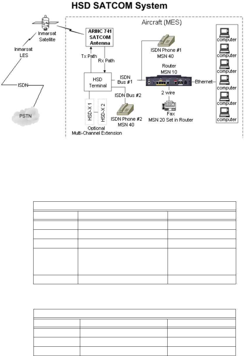
Page 2–9
18 September 2007
SYSTEM DESCRIPTION, INSTALLATION, AND MAINTENANCE MANUAL
eNfusion™ HSD-128 High-speed Data Terminal
Figure 2–2. System Setup and Mapping for Incoming Calls (Fixed-to-Mobile)
Note: Refer to Table 2–2, Table 2–3, and Table 2–4 for the default MSNs assigned
within the HSD system.
Table 2–2. IMN and MSN Assignments for ISDN Bus #1
Channel Card # 1 Forward ID XAXXXX
Service Type IMN MSN
64 kbps Speech 60xxxxxx1 (See Note below)MSN 40
3.1 kHz Audio 60xxxxxx2 MSN 20
56 kbps Data 60xxxxxx3 MSN 30
64 kbps Data 60xxxxxx4
60xxxxxx5
60xxxxxx6
MSN 10
MSN 11
MSN 12
4.8 kbps LSV 76xxxxxx7 through to 760xxxx22 MSN 80 through to 95
Table 2–3. IMN and MSN Assignments for ISDN Bus #2
Channel Card # 2 (if installed) Forward ID XBXXXX
Service Type IMN MSN
64 kbps Speech 60xxxxx23 MSN 40
3.1 kHz Audio 60xxxxx24 MSN 20
56 kbps Data 60xxxxx25 MSN 30

Page 2–10
18 September 2007
SYSTEM DESCRIPTION, INSTALLATION, AND MAINTENANCE MANUAL
eNfusion™ HSD-128 High-speed Data Terminal
Note: IMNs shown are examples only. Actual IMNs may not be assigned in
numerical sequence. HSD-X extension channels are assigned IMNs using
the same logic.
(a) Inmarsat Mobile Numbers
Inmarsat Mobile Numbers (IMNs) are unique routing numbers that act similarly
to telephone numbers. IMNs are assigned by Inmarsat to each service type (64
kbps Speech, 3.1 kHz Audio, 56 kbps Data, 64 kbps Data, and 4.8 kbps LSV).
When registering your system, request IMNs for each service-type device
attached to the HSD transceiver on the Service Activation form. Although the
service provider may support an unlimited number of IMNs assigned to a
particular system, the number of physical connections available on a system
defines the number of IMNs supported.
Note: To get assigned extra or multiple IMN per service type, you must request
them from your service provider when filling out your service registration
and application form.
The maximum a one-channel HSD transceiver supports is eight physical
connections to EURO ISDN devices. A two-channel HSD transceiver supports
up to sixteen physical connections to EURO ISDN devices. The maximum an
HSD-X transceiver supports is seven physical connections to EURO ISDN
devices.
Note: An HSD transceiver with a DATA I/O Card Type 2 installed (models
1110-A-1050 and 1110-A-0160 or other models with service bulletin,
1110-SB-0004 accomplished) only supports seven EURO-ISDN devices
on a one-channel card system. DATA I/O Card Type 2 systems can only
connect to one channel card in a two-channel-card, split-bus configuration
providing connectivity to fifteen devices in total.
The numbering of IMNs varies from one type of Inmarsat service to another. For
troubleshooting purposes understanding the IMN format can assist in verifying
that the correct service type is assigned to connecting devices. Inmarsat IMNs
(for this type of terminal) use the following nine-digit format:
IMN Format: T1- T2- X1- X2 -X3 -X4 -X5- X6- X7
Numerical Example:
• 760011819 (for 4.8 kbps AMBE LSV)
• 600221989 (for 64 kbps Data)
64 kbps Data 60xxxxx26
60xxxxx27
60xxxxx28
MSN 10
MSN 11
MSN 12
4.8 kbps LSV 76xxxxx29 through to 760xxxx44 MSN 80 through to 95
Table 2–3. IMN and MSN Assignments for ISDN Bus #2
Channel Card # 2 (if installed) Forward ID XBXXXX
Page 2–11
18 September 2007
SYSTEM DESCRIPTION, INSTALLATION, AND MAINTENANCE MANUAL
eNfusion™ HSD-128 High-speed Data Terminal
T1 and T2 are two-digit identifiers for Inmarsat service types. X1 to X7 can be
any digit between "0" and "9". The IMNs for Mini-M (4.8 kbps LSV) service type
are identified by the T1 and T2 numbers 7 and 6. The IMNs for the 56 kbps and
64 kbps service types (including ISDN Speech and 3.1 kHz audio) are identified
by the T1 and T2 numbers 6 and 0.
(b) Multiple Subscriber Numbers
Multiple Subscriber Numbers (MSNs) act as identification and routing codes for
user devices attached to the HSD system. MSNs identify the device on the
system so that incoming calls route to the appropriate device. Each device must
be assigned an appropriate MSN to identify to the Inmarsat system what type of
service that device needs on outgoing calls. The MSNs also provide routing
information for incoming calls.
For a simplified understanding of MSNs, equate them to telephone extension
numbers (where the IMN is the PBX telephone number and the MSN is the
extension number).
1. Configuring MSNs
Each HSD and HSD-X channel card is assigned one Forward ID and an IMN
for each service type the system is registered for with the service provider.
Table 2–4 provides the list of the MSN numbers recognized by the HSD
system. Both 64 kbps Data and Mini-M Voice (4.8 kbps LSV AMBE) services
support multiple MSNs. The MSNs are assigned to each IMN as follows:
• One MSN for the service types 64 kbps Speech, 3.1 kHz Audio, and 56
kbps Data
• Three MSNs for 64 kbps Data
• Sixteen MSNs for Mini-M Voice (4.8 kbps LSV AMBE)
(On control card software 4.1 or later—systems shipped from the factory
after November 15, 2002 have Version 4.1 software or later installed.)
The three MSNs assigned to 64 kbps ISDN support connection to three
separate devices mapped to the same IMN. Therefore, in dual-channel
systems, three ISDN devices can be connected to each channel provided six
separate mapping extensions; in three-channel systems, three ISDN devices
can be connected to each channel provided nine separate mapping
extensions; and, in four-channel systems, three ISDN devices can be
connected to each channel providing twelve separate mapping extensions.
The sixteen MSNs assigned to 4.8 kbps LSV support the mapping of sixteen
separate phones to the same IMN. (Example: sixteen phones connected to
a PBX box.) In dual and Multi-Channel systems, PBX devices can be
connected to each channel providing up to 64 separate phone extensions.
Note: Incoming voice calls will ring any phone devices not programmed with
an MSN (left blank) including 4.8 kbps LSV, 64 kbps Speech, and 3.1
kHz audio calls.
Configure all devices (e.g. telephones, fax machines, laptops) connected to
the HSD system with an appropriate MSN. (Refer to the device
manufacturer’s user documentation for specific instructions in how to enter
or configure the MSN.)

Page 2–12
18 September 2007
SYSTEM DESCRIPTION, INSTALLATION, AND MAINTENANCE MANUAL
eNfusion™ HSD-128 High-speed Data Terminal
Table 2–4. HSD Transceiver MSN Configuration Table
Forward ID Service Type IMN MSN
Channel Card #1 (XAXXXX) 64 kbps Speech 60xxxxxxx 40
Channel Card #2 (XBXXXX) -
Dual Channel Units
64 kbps Speech 60xxxxxxx 40
Channel Card #3 (XCXXXX) -
Multi-Channel HSD-X 1
64 kbps Speech 60xxxxxxx 40
Channel Card #4 (XDXXXX) -
Multi-Channel HSD-X 2
64 kbps Speech 60xxxxxxx 40
Channel Card #1 (XAXXXX) 3.1 kHz Audio 60xxxxxxx 20
Channel Card #2 (XBXXXX) -
Dual Channel Units
3.1 kHz Audio 60xxxxxxx 20
Channel Card #3 (XCXXXX) -
Multi-Channel HSD-X 1
3.1 kHz Audio 60xxxxxxx 20
Channel Card #4 (XDXXXX) -
Multi-Channel HSD-X 2
3.1 kHz Audio 60xxxxxxx 20
Channel Card # 1 (XAXXXX) 56 kbps Data 60xxxxxxx 30
Channel Card # 2 (XBXXXX) -
Dual Channel Units
56 kbps Data 60xxxxxxx 30
Channel Card #3 (XCXXXX) -
Multi-Channel HSD-X 1
56 kbps Data 60xxxxxxx 30
Channel Card #4 (XDXXXX) -
Multi-Channel HSD-X 2
56 kbps Data 60xxxxxxx 30
Channel Card # 1 (XAXXXX) 64 kbps Data 60xxxxxxx 10, 11, 12
Channel Card # 2 (XBXXXX) -
Dual Channel Units
64 kbps Data 60xxxxxxx 10, 11, 12
Channel Card #3 (XCXXXX) -
Multi-Channel HSD-X 1
64 kbps Data 60xxxxxxx 10, 11, 12
Channel Card #4 (XDXXXX) -
Multi-Channel HSD-X 2
56 kbps Data 60xxxxxxx 30
Channel Card #1 (XAXXXX) 4.8 kbps LSV
(Not supported in
Non-Stand-Alone
systems)
76xxxxxxx 80, 81, 82,
83, 84, 85,
86, 87, 88,
89, 90, 91,
92, 93, 94,
95
Channel Card #2 (XBXXXX) -
Dual Channel Units
4.8 kbps LSV
(Not supported in
Non-Stand-Alone
systems)
76xxxxxxx 80, 81, 82,
83, 84, 85,
86, 87, 88,
89, 90, 91,
92, 93, 94,
95

Page 2–13
18 September 2007
SYSTEM DESCRIPTION, INSTALLATION, AND MAINTENANCE MANUAL
eNfusion™ HSD-128 High-speed Data Terminal
Channel Card #3 (XCXXXX) -
Multi-Channel HSD-X 1
4.8 kbps LSV
(Not supported in
Non-Stand-Alone
systems)
76xxxxxxx 80, 81, 82,
83, 84, 85,
86, 87, 88,
89, 90, 91,
92, 93, 94,
95
Channel Card #4 (XDXXXX) -
Multi-Channel HSD-X 2
4.8 kbps LSV
(Not supported in
Non-Stand-Alone
systems)
76xxxxxxx 80, 81, 82,
83, 84, 85,
86, 87, 88,
89, 90, 91,
92, 93, 94,
95
Table 2–5. System Assignments for Incoming Calls (Fixed-to-Mobile)
Entry PERIPH MSN TID Call Type REDIR
0 ISDN NO_ID\ 1 800103 Mobile AMBE
1 Bonded NO_ID\ 1 800103 Mobile AMBE
2 ISDN NO_ID\ 91 800124 Mobile aero 64k speech
3 ISDN 10\ 51 800622 Mobile aero 64k UDI
4 ISDN 11\ 52 800622 Mobile aero 64k UDI
5 ISDN 12\ 53 800622 Mobile aero 64k UDI
6 ISDN NO_ID\ 51 800622 Mobile aero 64k UDI
7 Bonded NO_ID\ 51 800622 Mobile aero 64k UDI
8 ISDN 20\ 61 800625 Mobile aero 64k audio 3.1
9 ISDN NO_ID\ 61 800625 Mobile aero 64k audio 3.1
10 Bonded NO_ID\ 61 800625 Mobile aero 64k audio 3.1
11 ISDN 30\ 71 800623 Mobile aero 56k UDI
12 ISDN NO_ID\ 71 800623 Mobile aero 56k UDI
13 Bonded NO_ID\ 71 800623 Mobile aero 56k UDI
14 ISDN 40\ 91 800124 Mobile aero 64k speech
15 Bonded NO_ID\ 91 800124 Mobile aero 64k speech
16 ISDN 80 1 800103 Mobile AMBE (4.8 kbps
LSV)
17 ISDN 81 2 800103 Mobile AMBE (4.8 kbps
LSV)
18 ISDN 82 3 800103 Mobile AMBE (4.8 kbps
LSV)
19 ISDN 83 4 800103 Mobile AMBE (4.8 kbps
LSV)
Table 2–4. HSD Transceiver MSN Configuration Table
Forward ID Service Type IMN MSN

Page 2–14
18 September 2007
SYSTEM DESCRIPTION, INSTALLATION, AND MAINTENANCE MANUAL
eNfusion™ HSD-128 High-speed Data Terminal
C. Configuring System Parameters using the Maintenance Port Utility
This section describes how to configure the system parameters for all modes and
configurations of HSD operation, including: Stand-Alone Mode, Cooperative Mode,
Honeywell Combined Mode, Selective Mode, and Multi-Channel Configurations.
(1) Configuring System Parameters for Stand-Alone Mode
This section describes how to use the HSD Maintenance Port Utility to configure the
HSD system parameters for operation in Stand-Alone Mode.
Refer to "Test and Fault Isolation" on page 4-1 for detailed instructions on how to
connect to and use the HSD Maintenance Port Utility Program.
When all the required system parameters have been configured, “reset” or cycle the
power on the HSD to activate the new configuration.
To configure the required system parameters first establish a connection to the HSD
Maintenance Port Utility program:
• Connect a computer to the maintenance port of the HSD transceiver as described
in "Test and Fault Isolation" on page 4-1, and then power up the system.
• Using a terminal emulation program, open the HSD maintenance utility program.
20 ISDN 84 5 800103 Mobile AMBE (4.8 kbps
LSV)
21 ISDN 85 6 800103 Mobile AMBE (4.8 kbps
LSV)
22 ISDN 86 7 800103 Mobile AMBE (4.8 kbps
LSV)
23 ISDN 87 8 800103 Mobile AMBE (4.8 kbps
LSV)
24 ISDN 88 9 800103 Mobile AMBE (4.8 kbps
LSV)
25 ISDN 89 A 800103 Mobile AMBE (4.8 kbps
LSV)
26 ISDN 90 B 800103 Mobile AMBE (4.8 kbps
LSV)
27 ISDN 91 C 800103 Mobile AMBE (4.8 kbps
LSV)
28 ISDN 92 D 800103 Mobile AMBE (4.8 kbps
LSV)
29 ISDN 93 E 800103 Mobile AMBE (4.8 kbps
LSV)
30 ISDN 94 F 800103 Mobile AMBE (4.8 kbps
LSV)
31 ISDN 95 10 800103 Mobile AMBE (4.8 kbps
LSV)
Table 2–5. System Assignments for Incoming Calls (Fixed-to-Mobile)
Entry PERIPH MSN TID Call Type REDIR

Page 2–15
18 September 2007
SYSTEM DESCRIPTION, INSTALLATION, AND MAINTENANCE MANUAL
eNfusion™ HSD-128 High-speed Data Terminal
• Type the password maint. (The password does not appear on the screen.)
The HSD Maintenance Port Utility Program Menu 1 appears. You are now ready to
begin configuring the system parameters for Stand-Alone operation as described in
the following sections.
(a) Configuring the Terminal Category for Stand-Alone Mode
The factory default for the Terminal Category is configured to “2=HW Strapping.”
If the HSD transceiver does not have the recommended hardware strapping for
system configuration installed, the terminal category must be configured using
the HSD Maintenance Port EEPROM parameters.
To configure the Terminal Category:
1. In Menu 3, to select misc. EEPROM parameters press M.
The Miscellaneous Parameters list appears. The available parameters may
differ depending on the version of control processor software installed.
2. To select the Terminal Category, type 16 and then press Enter.
The Terminal Category Menu appears.
3. Type 1 for Stand-Alone and then press Enter.
A system message appears stating that the EEPROM has been updated.
This completes the configuration of the terminal category.
You now need to configure the LES Access Codes.
MENU 3 FIRMWARE Vx.x
L list EEPROM S list event log
M misc. EEPROM parameter F list call log
O list ORT P ocean region parameter
I set all LES id’s
<CTRL> N next menu <CTRL> O previous menu = select reports
MISCELLANEOUS PARAMETERS
1 HPA-TO-ANTENNA TOTAL LOSS 11 FRONT PANEL LEDS ENABLED
2 FORWARD ID 14 MAINTENANCE PORT INVERSE VIDEO
3 GPS PROTECTION ALGORITHMS 15 MAINTENANCE PORT DEGREES SYMBOL
4 REGISTRATION REQ'D BEFORE CALLS 16 TERMINAL CATEGORY
10 NUMBER OF CHANNEL CARDS 17 VIPER ANTENNA GAIN
TERMINAL CATEGORY
WHICH PARAMETER # ? 16
TERMINAL CATEGORY HW STRAPPED VALUE
0=SAT906 1=STANDALONE 2=HW STRAPPING 3=MCS3000 4=MCS6000 5=MCS7000
6=MCS COMB 7=STANDALONE W/O ANTENNA 8=HCM COMBINED
9=COOPERATIVE ROCKWELL-COLLINS SAT906 10=OLD COMBINED MODE DEVELOP
11=HSD-X NETWORK 12=HSD-X NETWORK W/O ANTENNA 13=VIPER
NEW TERMINAL CATEGORY = ? 1

Page 2–16
18 September 2007
SYSTEM DESCRIPTION, INSTALLATION, AND MAINTENANCE MANUAL
eNfusion™ HSD-128 High-speed Data Terminal
(2) Configuring System Parameters for Cooperative Mode
This section describes how to use the HSD Maintenance Port Utility to configure the
HSD system parameters for operation in Cooperative Mode.
Refer to "Test and Fault Isolation" on page 4-1 for detailed instructions on how to
connect to and use the HSD Maintenance Port Utility Program.
When all the required system parameters have been configured, “reset” or cycle the
power on the HSD to activate the new configuration.
To configure the required system parameters first establish a connection to the HSD
Maintenance Port Utility program:
• Connect a computer to the maintenance port of the HSD transceiver as described
in "Test and Fault Isolation" on page 4-1, and then power up the system.
• Using a terminal emulation program, open the HSD maintenance utility program.
• Type the password MAINT. (The password does not appear on the screen.)
The HSD Maintenance Port Utility Program menus appear. You are now ready to
begin configuring the system parameters for Cooperative Mode operation as
described in the following sections.
(a) Configuring the Terminal Category for Cooperative Mode
If the HSD transceiver does not have the recommended hardware strapping for
system configuration installed, the terminal category must be configured using
the HSD Maintenance Port EEPROM parameters.
To configure the Terminal Category:
1. In Menu 3, to select misc. EEPROM parameters press M.
The Miscellaneous Parameters list appears. The available parameters may
differ depending on the version of control processor software installed.
2. To select the Terminal Category, type 16 and then press Enter.
The Terminal Category Menu appears.
MENU 3 FIRMWARE Vx.x
L list EEPROM S list event log
M misc. EEPROM parameter F list call log
O list ORT P ocean region parameter
I set all LES id’s
<CTRL> N next menu <CTRL> O previous menu = select reports
MISCELLANEOUS PARAMETERS
1 HPA-TO-ANTENNA TOTAL LOSS 11 FRONT PANEL LEDS ENABLED
2 FORWARD ID 14 MAINTENANCE PORT INVERSE VIDEO
3 GPS PROTECTION ALGORITHMS 15 MAINTENANCE PORT DEGREES SYMBOL
4 REGISTRATION REQ'D BEFORE CALLS 16 TERMINAL CATEGORY
10 NUMBER OF CHANNEL CARDS 17 VIPER ANTENNA GAIN
WHICH PARAMETER # <CTRL> N for next page ? 16

Page 2–17
18 September 2007
SYSTEM DESCRIPTION, INSTALLATION, AND MAINTENANCE MANUAL
eNfusion™ HSD-128 High-speed Data Terminal
3. Type 9 for Cooperative Rockwell-Collins SAT-906 and then press Enter.
A system message appears stating that the EEPROM has been updated.
(b) Configuring the Number of Channel Cards
HSD transceivers operating in Cooperative Mode must be configured as
single-channel units—even if the unit is a dual-channel transceiver.
To configure the transceiver as a Single Channel system:
1. In Menu 3, press M.
2. Type 10 to select the “Number of Channel Cards” parameter and then press
Enter.
3. Type 1 for the number of channel cards and then press Enter.
A system message appears stating that the EEPROM has been updated.
This completes the configuration of the system’s number of channel cards.
You now need to configure the LES Access Codes as described in
"Configuring LES Access Codes (All Modes)" on page 2-24.
(3) Configuring System Parameters for Honeywell Combined Mode
To operate the HSD transceiver in Honeywell Combined Mode, you need to configure
the following system parameters using the Honeywell SATCOM Direct
Commissioning and Maintenance Terminal (CMT) and the HSD Maintenance Port
Utility.
To configure the Honeywell System Parameters:
1. First, use the Honeywell CMT to:
• Obtain the HPA to antenna loss from the Honeywell SDU
• Configure High Rate Data Support settings (recommended—but not
mandatory)
2. Then use the HSD Maintenance Port Utility to:
• Configure the Terminal Category (only required when the recommended
hardware strapping is not used)
• Set Swift64 (M4) and Aero service priorities
• Change the LES Access Codes
• Reset the system to activate the new configuration.
TERMINAL CATEGORY HW STRAPPED VALUE
0=SAT906 1=STANDALONE 2=HW STRAPPING 3=MCS3000 4=MCS6000 5=MCS7000
6=MCS COMB 7=STANDALONE W/O ANTENNA 8=HCM COMBINED
9=COOPERATIVE ROCKWELL-COLLINS SAT906 10=OLD COMBINED MODE DEVELOP
11=HSD-X NETWORK 12=HSD-X NETWORK W/O ANTENNA 13=VIPER
NEW TERMINAL CATEGORY = ? 9
Page 2–18
18 September 2007
SYSTEM DESCRIPTION, INSTALLATION, AND MAINTENANCE MANUAL
eNfusion™ HSD-128 High-speed Data Terminal
(a) Step One: Honeywell System Configuration
Using the Honeywell SATCOM Direct CMT, obtain the antenna loss parameter
and configure the High Rate Data Support settings.
The connection to the Honeywell SATCOM Direct CMT Port uses an RS-232
interface with any “VT-100” terminal emulator program. Configure your VT-100
terminal settings as follows: 9600 bps, no parity, 8 data bits, and 1 stop bit. Refer
to Honeywell provided documentation for more information.
To configure the Honeywell System:
1. Obtain the HPA to Antenna Loss Parameter Value
To maximize system performance, adjust the HPA-to-Antenna Loss
parameter within the HSD system to accommodate the HPA to antenna loss
from the Honeywell SDU.
• Using the Honeywell CMT, obtain the value of the HPA to antenna loss
from the Honeywell SDU.
• Record the HPA to antenna loss value for future reference. Typically, the
value is between 1.5 dB and 2.5 dB. Enter this antenna-loss value into the
HSD system configuration using the HSD transceiver’s Maintenance Port
Utility Program.
2. Configure the High Rate Data Support Settings
Usually, the High Rate Data Support parameters of the Honeywell SDU
(Global Beam, High Rate Data and Spot Beam, High Rate Data) are
configured to “DIS/EN” (disabled/enabled). Although not mandatory, setting
both parameters to “disabled” is recommended.
(b) Step Two: Configuring the HSD Transceiver for HCM Mode
This section describes how to use the HSD Maintenance Port Utility to configure
the HSD system parameters for operation in HCM Mode.
Refer to "Test and Fault Isolation" on page 4-1 for detailed instructions on how
to connect to and use the HSD Maintenance Port Utility Program.
When all the required system parameters have been configured, the HSD must
be “reset” to activate the new configuration. To configure the required system
parameters first establish a connection to the HSD Maintenance Port Utility
program:
• Connect a computer to the maintenance port of the HSD transceiver as
described in "Test and Fault Isolation" on page 4-1, and then power up the
system.
• Using a terminal emulation program, open the HSD maintenance utility
program.
• Type the password MAINT. (The password does not appear on the screen.)
The HSD Maintenance Port Utility Program menus appear. You are now ready
to begin configuring the system parameters for HCM operation as described in
the following sections.

Page 2–19
18 September 2007
SYSTEM DESCRIPTION, INSTALLATION, AND MAINTENANCE MANUAL
eNfusion™ HSD-128 High-speed Data Terminal
1. Configuring the Terminal Category for Combined Mode
If the HSD transceiver does not have the recommended hardware strapping
for system configuration installed, configure the terminal category using the
HSD Maintenance Port EEPROM parameters as described in the following
procedure.
To configure the Terminal Category:
1. In Menu 3, to select misc. EEPROM parameters press M.
The Miscellaneous Parameters list appears. The available parameters
may differ depending on the version of control processor software
installed.
2. To select the Terminal Category, type 16 and then press Enter.
The Terminal Category Menu appears.
3. Type 8 for HCM Combined and then press Enter.
A system message appears stating that the EEPROM has been updated.
This completes the configuration of the terminal category.
2. Configuring Antenna Loss
To configure the Antenna Loss:
1. In Menu 3, to select misc. EEPROM parameters, press M.
The Miscellaneous Parameters list appears.
MENU 3 FIRMWARE Vx.x
L list EEPROM S list event log
M misc. EEPROM parameter F list call log
O list ORT P ocean region parameter
I set all LES id’s
<CTRL> N next menu <CTRL> O previous menu = select reports
MISCELLANEOUS PARAMETERS
1 HPA-TO-ANTENNA TOTAL LOSS 11 FRONT PANEL LEDS ENABLED
2 FORWARD ID 14 MAINTENANCE PORT INVERSE VIDEO
3 GPS PROTECTION ALGORITHMS 15 MAINTENANCE PORT DEGREES SYMBOL
4 REGISTRATION REQ'D BEFORE CALLS 16 TERMINAL CATEGORY
10 NUMBER OF CHANNEL CARDS 17 VIPER ANTENNA GAIN
WHICH PARAMETER # <CTRL> N for next page ? 16
TERMINAL CATEGORY HW STRAPPED VALUE
0=SAT906 1=STANDALONE 2=HW STRAPPING 3=MCS3000 4=MCS6000 5=MCS7000
6=MCS COMB 7=STANDALONE W/O ANTENNA 8=HCM COMBINED
9=COOPERATIVE ROCKWELL-COLLINS SAT906 10=OLD COMBINED MODE DEVELOP
11=HSD-X NETWORK 12=HSD-X NETWORK W/O ANTENNA 13=VIPER
NEW TERMINAL CATEGORY = ? 8

Page 2–20
18 September 2007
SYSTEM DESCRIPTION, INSTALLATION, AND MAINTENANCE MANUAL
eNfusion™ HSD-128 High-speed Data Terminal
2. To select the HPA Antenna Cable Loss parameter, type 1
3. Press Enter.
The current value for HPA to antenna cable loss appears.
4. Enter the “HPA to Antenna Cable Loss” value recorded from the Honeywell
SDU, and then press Enter.
Note: The loss refers to the total loss from the HPA to the antenna,
including the coax cable and the DLNA insertion loss (typically 0.8
dB maximum).
A system message appears stating that the EEPROM has been updated.
This completes the configuration of the HPA to Antenna Cable Loss
parameter.
3. Configuring Service Priority
The HSD system can be configured to give priority to either Aero H or M4
(HCM HSD Swif64) communications. The system default gives priority to
Aero H communications.
If the HSD parameter is set to Aero priority, the SATCOM Aero H calls are
given the priority for power consumption when HPA resources become
limited. If the HSD parameter is set to M4 priority, M4 calls have priority when
HPA resources become limited.
To configure the Service Priority:
1. In Menu 3, press M for misc. EEPROM parameters.
The Miscellaneous Parameters List appears.
MENU 3 FIRMWARE Vx.x
L list EEPROM S list event log
M misc. EEPROM parameter F list call log
O list ORT P ocean region parameter
I set all LES id’s
<CTRL> N next menu <CTRL> O previous menu = select reports
MISCELLANEOUS PARAMETERS
1 HPA-TO-ANTENNA TOTAL LOSS 11 FRONT PANEL LEDS ENABLED
2 FORWARD ID 14 MAINTENANCE PORT INVERSE VIDEO
3 GPS PROTECTION ALGORITHMS 15 MAINTENANCE PORT DEGREES SYMBOL
4 REGISTRATION REQ'D BEFORE CALLS 16 TERMINAL CATEGORY
10 NUMBER OF CHANNEL CARDS 17 VIPER ANTENNA GAIN
WHICH PARAMETER # <CTRL> N for next page ? 1
HPA-ANTENNA CABLE LOSS 2.5 dB = ?

Page 2–21
18 September 2007
SYSTEM DESCRIPTION, INSTALLATION, AND MAINTENANCE MANUAL
eNfusion™ HSD-128 High-speed Data Terminal
2. To select HCM Aero/M4 Prioritization, type 42 and then press Enter.
The system prompts you to select a service priority.
3. Set the service priority for the system as follows:
• To select M4 services as the system priority, type 1 then press Enter.
• To select Aero services as the system priority, type 0 (the number
zero) then press Enter (as displayed in the example provided above).
A system message appears stating that the EEPROM has been updated.
This completes the configuration of service priority. You now need to
configure the LES Access Codes.
(4) Configuring System Parameters for Selective Mode
This section describes how to use the HSD Maintenance Port Utility to configure the
HSD system parameters for operation in Selective Mode.
Refer to "Test and Fault Isolation" on page 4-1 for detailed instructions on how to
connect to and use the HSD Maintenance Port Utility Program.
When all the required system parameters have been configured, “reset” or cycle the
power on the HSD to activate the new configuration.
To configure the required system parameters first establish a connection to the HSD
Maintenance Port Utility program:
• Connect a computer to the maintenance port of the HSD transceiver as described
in "Test and Fault Isolation" on page 4-1, and then power up the system.
• Using a terminal emulation program, open the HSD maintenance utility program.
• Type the password MAINT. (The password does not appear on the screen.)
MISCELLANEOUS PARAMETERS
1 HPA-TO-ANTENNA TOTAL LOSS 11 FRONT PANEL LEDS ENABLED
2 FORWARD ID 14 MAINTENANCE PORT INVERSE VIDEO
3 GPS PROTECTION ALGORITHMS 15 MAINTENANCE PORT DEGREES SYMBOL
4 REGISTRATION REQ'D BEFORE CALLS 16 TERMINAL CATEGORY
10 NUMBER OF CHANNEL CARDS 17 VIPER ANTENNA GAIN
WHICH PARAMETER # <CTRL> N for next page ?
18 VIPER HPA/ANT LOSS 31 OBEY OXCO STATUS
24 RECEIVER CALIBRATION 42 HCM AERO/M4 PRIORITIZATION
28 RX32 ACTIVE 45 CATEGORY B LOWER FREQUENCY LIMIT
29 DEFAULT LATITUDE 46 CATEGORY B UPPER FREQUENCY LIMIT
30 DEFAULT LONGITUDE…….
WHICH PARAMETER #.? 42
HCM AERO/M4 PRIORITIZATION AERO (1=M4 0=AERO) = ? 0
EEPROM UPDATED

Page 2–22
18 September 2007
SYSTEM DESCRIPTION, INSTALLATION, AND MAINTENANCE MANUAL
eNfusion™ HSD-128 High-speed Data Terminal
The HSD Maintenance Port Utility Program menus appear. You are now ready to
begin configuring the system parameters for Selective Mode operation as described
in the following procedure.
(a) Configuring the Terminal Category for Selective Mode
If the HSD transceiver does not have the recommended hardware strapping for
system configuration installed, the terminal category must be configured using
the HSD Maintenance Port EEPROM parameters.
To configure the Terminal Category:
1. In Menu 3, to select misc. EEPROM parameters press M.
The Miscellaneous Parameters list appears. The available parameters may
differ depending on the version of control processor software installed.
2. To select the Terminal Category, type 16 and then press Enter.
The Terminal Category Menu appears.
3. Type the appropriate terminal category number required Selective Mode (0,
3, 4, 5, or 6), and then press Enter.
A system message appears stating that the EEPROM has been updated.
This completes the configuration of the terminal category. You now need to
configure the LES Access Codes as described on page 24.
MENU 3 FIRMWARE Vx.x
L list EEPROM S list event log
M misc. EEPROM parameter F list call log
O list ORT P ocean region parameter
I set all LES id’s
<CTRL> N next menu <CTRL> O previous menu = select reports
MISCELLANEOUS PARAMETERS
1 HPA-TO-ANTENNA TOTAL LOSS 11 FRONT PANEL LEDS ENABLED
2 FORWARD ID 14 MAINTENANCE PORT INVERSE VIDEO
3 GPS PROTECTION ALGORITHMS 15 MAINTENANCE PORT DEGREES SYMBOL
4 REGISTRATION REQ'D BEFORE CALLS 16 TERMINAL CATEGORY
10 NUMBER OF CHANNEL CARDS 17 VIPER ANTENNA GAIN
WHICH PARAMETER # <CTRL> N for next page ? 16
TERMINAL CATEGORY HW STRAPPED VALUE
0=SAT906 1=STANDALONE 2=HW STRAPPING 3=MCS3000 4=MCS6000 5=MCS7000
6=MCS COMB 7=STANDALONE W/O ANTENNA 8=HCM COMBINED
9=COOPERATIVE ROCKWELL-COLLINS SAT906 10=OLD COMBINED MODE DEVELOP
11=HSD-X NETWORK 12=HSD-X NETWORK W/O ANTENNA 13=VIPER
NEW TERMINAL CATEGORY = ? 3

Page 2–23
18 September 2007
SYSTEM DESCRIPTION, INSTALLATION, AND MAINTENANCE MANUAL
eNfusion™ HSD-128 High-speed Data Terminal
(5) Configuring System Parameters for Multi-Channel Configurations
This section describes how to use the HSD Maintenance Port Utility to configure the
HSD system parameters for operation in Multi-Channel Configurations.
Refer to "Test and Fault Isolation" on page 4-1 for detailed instructions on how to
connect to and use the HSD Maintenance Port Utility Program.
When all the required system parameters have been configured, “reset” or cycle the
power on the HSD to activate the new configuration.
To configure the required system parameters first establish a connection to the HSD
Maintenance Port Utility program:
• Connect a computer to the maintenance port of the HSD transceiver as described
in "Test and Fault Isolation" on page 4-1, and then power up the system.
• Using a terminal emulation program, open the HSD maintenance utility program.
• Type the password MAINT. (The password does not appear on the screen.)
The HSD Maintenance Port Utility Program Menu 1 appears. You are now ready to
begin configuring the system parameters for Multi-Channel operation as described in
the following sections.
(a) Configuring the Terminal Category for Multi-Channel
If the HSD transceiver does not have the recommended hardware strapping for
system configuration installed, the terminal category must be configured using
the HSD Maintenance Port EEPROM parameters.
To configure the Terminal Category:
1. In Menu 3, to select misc. EEPROM parameters press M.
The Miscellaneous Parameters list appears. The available parameters may
differ depending on the version of control processor software installed.
2. To select the Terminal Category, type 16 and then press Enter.
The Terminal Category Menu appears.
MENU 3 FIRMWARE Vx.x
L list EEPROM S list event log
M misc. EEPROM parameter F list call log
O list ORT P ocean region parameter
I set all LES id’s
<CTRL> N next menu <CTRL> O previous menu = select reports
MISCELLANEOUS PARAMETERS
1 HPA-TO-ANTENNA TOTAL LOSS 11 FRONT PANEL LEDS ENABLED
2 FORWARD ID 14 MAINTENANCE PORT INVERSE VIDEO
3 GPS PROTECTION ALGORITHMS 15 MAINTENANCE PORT DEGREES SYMBOL
4 REGISTRATION REQ'D BEFORE CALLS 16 TERMINAL CATEGORY
10 NUMBER OF CHANNEL CARDS 17 VIPER ANTENNA GAIN
WHICH PARAMETER # <CTRL> N for next page ? 16

Page 2–24
18 September 2007
SYSTEM DESCRIPTION, INSTALLATION, AND MAINTENANCE MANUAL
eNfusion™ HSD-128 High-speed Data Terminal
3. Type the appropriate terminal category number appropriate Multi-Channel
Configuration (11, 12, or 13), and then press Enter.
A system message appears stating that the EEPROM has been updated.
This completes the configuration of the terminal category. You now need to
configure the LES Access Codes.
D. Configuring LES Access Codes (All Modes)
This section describes how to configure the LES access codes provided by your Inmarsat
service provider in HSD and HSD-X transceivers.
Note: You can remove the label that covers the LES Access Codes LEDs once you have
configured the LES Access Codes.
(1) General Overview
Inmarsat Service Providers (ISPs) operate Land Earth Stations (LES). The ISPs are
typically public telephone companies of the country where the LES is located.
Using satellite communications antennae and up-and-downlink communications
equipment, the LES converts the space segment to a format compatible with public
and private telephone and data networks. Each satellite is associated with a number
of LES that fall within its coverage.
Inmarsat assigns each LES an access code. These access codes are used by the
Inmarsat system to route calls to the correct Ocean Region Satellite and LES.
New and upgraded HSD units, with Control Processor software version 5.7 or later,
are shipped with the factory default LES Access Codes set to ‘0’ (zero). All HSD units
(including HSD-X units in Multi-Channel configurations) must be configured with the
valid LES Access Codes provided by your Inmarsat Service Provider.
(a) Changing Default LES using the HSD Maintenance Port Utility Program
The LES access codes can be configured using the HSD Maintenance Port Utility
Program accessed by connecting a computer running a VT100 terminal
emulation program to the RS-232 Maintenance Port on the HSD (or HSD-X)
transceivers (refer to "Test and Fault Isolation" on page 4-1 for connection
settings and cabling information).
The LES access codes for HSD-X transceivers can either be configured directly,
through the HSD-X RS-232 Maintenance Port, or by “passing through” the
HSD-128 by activating the console mode feature. (To activate console mode, in
menu 18, press X).
When configuring the LES access codes using the HSD Maintenance Port Utility,
the application requests the input of a Secondary LES Access Code. At the time
of writing, the Inmarsat LES have not implemented the recognition of the
TERMINAL CATEGORY HW STRAPPED VALUE
0=SAT906 1=STANDALONE 2=HW STRAPPING 3=MCS3000 4=MCS6000 5=MCS7000
6=MCS COMB 7=STANDALONE W/O ANTENNA 8=HCM COMBINED
9=COOPERATIVE ROCKWELL-COLLINS SAT906 10=OLD COMBINED MODE DEVELOP
11=HSD-X NETWORK 12=HSD-X NETWORK W/O ANTENNA 13=VIPER
NEW TERMINAL CATEGORY = ? 11
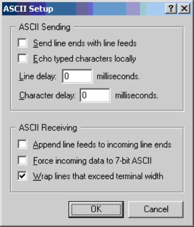
Page 2–25
18 September 2007
SYSTEM DESCRIPTION, INSTALLATION, AND MAINTENANCE MANUAL
eNfusion™ HSD-128 High-speed Data Terminal
secondary LES value in their systems. However, a valid Secondary LES Access
Code must be entered in the HSD system. The Secondary LES Access Code
must be the same as the Primary LES Access Code.
When operating HSD software version 5.7, DO NOT select the “Send line ends
with line feeds” option in the terminal emulation program’s ASCII Setup. (See
example dialog box presented in Figure 2–3.) If this ASCII Sending option is
selected, the LES Access Code entered in Menu 3 using the “P” command codes
will not be updated or saved to EEPROM.
Figure 2–3. Terminal Emulation Program, ASCII Setup
HSD transceivers with earlier versions of control processor software (5.4 or
earlier) are set with a factory default LES access code of 001. When installing
and commissioning the HSD transceiver, change the factory-set default LES for
each Ocean Region to the LES access codes provided by your Inmarsat Service
Provider.
Table 2–6 provides LES access codes for the service providers providing Swift64
services at the time of publication. Contact Inmarsat directly for an up-to-date list
of LES and Swift64 service providers.
For more information visit Inmarsat’s Web site at www.inmarsat.com/swift64 or
contact their Customer Care Service at:
Telephone: +44 20 7728 1777
Fax: +44 20 7728 1142
E-mail: customer_care@inmarsat.com

Page 2–26
18 September 2007
SYSTEM DESCRIPTION, INSTALLATION, AND MAINTENANCE MANUAL
eNfusion™ HSD-128 High-speed Data Terminal
Note: *When using the LES code 001 for Telenor, calls are automatically routed
to the appropriate service (either Swift64 LSV or Swift64 HSD, as defined
by the OD/ID code of the call). No additional user action is required.
Contact Inmarsat for an up-to-date listing of service providers. Contact
your service provider for more information on the services they provide.
(b) Equipment Required
The following equipment is required to change the default LES access code in
an HSD system (HSD or HSD-X transceivers):
• Computer (Laptop or PC)
• Windows 95® or later (Window 2000® recommended)
• HSD control processor software 4.1 or later
• Terminal emulation program (e.g. HyperTerminal)
(c) Connecting to the HSD Maintenance Port
Connect a PC/laptop running a terminal emulation program (e.g., HyperTerminal)
to the HSD maintenance port, and then power up the system. (Refer to "Test and
Fault Isolation" on page 4-1 for detailed connection information.)
Table 2–6. Inmarsat Swift64 LES Status (As of January, 2004)
Ocean
Region
Service Provider
(LES)
Global LES
Access
Code
Service Status
AORE Stratos Mobile
Networks (Satcom
Direct)
002 Swift64 – Low Speed Voice
(LSV)/HSD (Secure LSV–
future availability)
AORE Xantic (Station 12) 012 Swift64 LSV/HSD
AORE Telenor USA 001* Swift64 LSV
AORW Stratos Mobile
Networks
(Satcom Direct)
002 Swift64 – Low Speed Voice
(LSV)/HSD (Secure LSV–
future availability)
AORW Xantic (Station 12) 012 Swift64 LSV/HSD
AORW Telenor USA 001* Swift64 LSV
IOR Stratos Mobile
Networks
(Satcom Direct)
002 Swift64 – Low Speed Voice
(LSV)/HSD (Secure LSV–
future availability)
IOR Xantic (Telstra) 022 Swift64 LSV/HSD
IOR Telenor USA 001* Swift64 LSV/HSD
POR Stratos New Zealand
(Satcom Direct)
002 Swift64 – Low Speed Voice
(LSV)/HSD (Secure LSV–
future availability)
POR Xantic (Telstra) 022 Swift64 LSV/HSD
POR Telenor USA 001* Swift64 LSV

Page 2–27
18 September 2007
SYSTEM DESCRIPTION, INSTALLATION, AND MAINTENANCE MANUAL
eNfusion™ HSD-128 High-speed Data Terminal
(d) Changing LES access codes on a call-by-call basis
The following procedure provides detailed instructions in how to change the LES
default access code for HSD and HSD-X transceivers.
Note: This procedure provides instructions on how to change the HSD system
default for LES selection. You can also change the LES code on a
call-by-call basis using the dial code prefix 901 when troubleshooting and
diagnosing network problems.
To change the LES access code on a call-by-call basis in all control processor
software versions:
• Enter the following dial-sequence (Xantic POR LES Access Code (022) used
as an example only):
(e) Changing LES access codes using control processor software version 5.4 (and
earlier)
To change the HSD or HSD-X default LES access code in systems operating
control processor software version 5.4 or earlier:
1. Connect a computer to the maintenance port of the HSD transceiver, and
then power up system.
2. Using a terminal emulation program, open the HSD maintenance
utility program.
3. Type the password MAINT. (The password will not appear on the screen.)
4. Press Ctrl+N (repeatedly) to scroll down to Menu 3.
Menu 3 appears.
5. For miscellaneous EEPROM parameters, press M.
The Miscellaneous Parameters list appears.
901 + LES CODE + International Code + Country Code + Area Code + Telephone Number + #
Example: 901 + 022 + 00 + 1+ 613+5551212 + #
MENU 3 FIRMWARE Vx.x
L list EEPROM S list event log
E reset EEPROM C clear event log
M misc. EEPROM parameter J ignored faults
N system serial number F list call log
G clear call log
<CTRL> N next menu <CTRL> O previous menu = select reports

Page 2–28
18 September 2007
SYSTEM DESCRIPTION, INSTALLATION, AND MAINTENANCE MANUAL
eNfusion™ HSD-128 High-speed Data Terminal
6. Type in the parameter number for the Ocean Region LES access code you
want to change (i.e. 3, 21, 22, or 23), and then press Enter.
The program prompts you to type in the LES access code.
7. Type in the Ocean Region LES access code, and then press Enter.
Note: You may change one or all of the LES defaults. Each must be entered
separately. Refer to Table 2–6 for access codes of the LES service
providers available at the time of publication. Contact Inmarsat directly
for the most up-to-date service provider and LES access code
information.
8. In each parameter, enter a valid LES access code as needed.
CAUTION: Do not change the Satellite Longitude parameter—press Enter
to continue.
9. Reset the system. (In menu 2, press Z to reset the system, cycle the power
to the HSD transceiver, or press the front panel “Test” button or the remote
reset switch.)
Note: To activate the new default LES code(s) reset the system. If you
change the default LES code(s), but do not reset the system, the
system uses the “original” or previous default LES code(s)—even
though the “new” LES codes appear in the MENU 3 EEPROM
Listing—the new codes are activated (or loaded) when the system is
reset or the power is cycled.
To confirm the activation of new LES access code after resetting the system:
1. In Menu 3, press L.
2. The EEPROM Listing appears. Confirm that the new LES access codes are
displayed correctly. (See bolded parameters below.)
MISCELLANEOUS PARAMETERS
1 HPA-ANTENNA CABLE LOSS 18 AOR E VALID BEAMS
2 FORWARD ID 19 POR VALID BEAMS
3 AORW LES ACCESS CODE 20 IOR VALID BEAMS
4 TERRESTRIAL NETWORK ID 21 AORE LES ACCESS CODE
5 HPA-CHANNEL CARD CABLE LOSS 22 POR LES ACCESS CODE
6 MAX HPA GAIN 23 IOR LES ACCESS CODE
7 MIN ANTENNA GAIN 24 RECEIVER CALIBRATION (AERO)
8 MAX EIRP 25 MAX HPA POWER
9 MAX CHANNEL_CARD POWER 26 HPA RESERVED POWER (AERO)
10 NUMBER OF CHANNEL CARDS 27 CHANNEL CARD STARTUP DELAY
11 FRONT PANEL LEDS ENABLED 28 RX32 ACTIVE
12 RX ATTENUATION (LAND-ON-WINGS) 29 DEFAULT LATITUDE
13 MIN SECS BETWEEN CHAN CARD RESETS 30 DEFAULT LONGITUDE
14 MAINTENANCE PORT INVERSE VIDEO 31 OBEY OXCO STATUS
15 MAINTENANCE PORT DEGREES SYMBOL 32 CC DEBUG PORT
16 TERMINAL CATEGORY 33 COMBINED MODE BACKOFF ADJUSTMENT
17 AOR W VALID BEAMS
WHICH PARAMETER # ?

Page 2–29
18 September 2007
SYSTEM DESCRIPTION, INSTALLATION, AND MAINTENANCE MANUAL
eNfusion™ HSD-128 High-speed Data Terminal
(f) Changing LES access codes using control processor software version 5.7 (or
later)
To change individual LES access codes in systems operating software version
5.7 up to version 7.0:
EEPROM LISTING:
MAGIC NUMBER :OK
EEPROM VERSION NUMBER 2001
FIRMWARE VERSION 1018
SERIAL NUMBER: 114
IGNORED FAULTS: 0
HARDWARE CONFIG: 0
NUMBER OF POWERUPS (index 0) 13
HOURS OF OPERATION (index 0) 49
MISCELLANEOUS PARAMETERS
HIT 'L' for MORE
MISCELLANEOUS PARAMETERS
HIT 'L' for MORE
HPA-ANTENNA CABLE LOSS: 2.5 dB
FORWARD ID: 000000
AORW LES ACCESS CODE: 1
TERRESTRIAL NETWORK ID: 0
HPA-CHANNEL CARD CABLE LOSS: 10.0 dB
MAX HPA GAIN: 65.0 dB
MIN ANTENNA GAIN: 11.0 dB
MAX EIRP: 53.5 dBm
MAX CHANNEL_CARD POWER: 0.0 dBm
NUMBER OF CHANNEL CARDS : 2
FRONT PANEL LEDS ENABLED: 1
RX ATTENUATION (LAND-ON-WINGS): 0.0 dB
MIN SECS BETWEEN CHAN CARD RESETS: 300
HIT 'L' for MORE
MAINTENANCE PORT INVERSE VIDEO: 0
MAINTENANCE PORT DEGREES SYMBOL: 0
TERMINAL CATEGORY: HW STRAPPED VALUE
AOR W VALID BEAMS: 4 5 6
AOR E VALID BEAMS: 5 6
POR VALID BEAMS: 4 5 6
IOR VALID BEAMS: 5 6
AORE LES ACCESS CODE: 1
POR LES ACCESS CODE: 1
IOR LES ACCESS CODE: 1
RECEIVER CALIBRATION (AERO): 11.0 dB
MAX HPA POWER: 18.0 dBw
HPA RESERVED POWER (AERO): 16.0 dBw
HIT 'L' for MORE
CHANNEL CARD STARTUP DELAY: 30 sec
RX32 ACTIVE: 1
DEFAULT LATITUDE: 45 D 0' 0.0" N
DEFAULT LONGITUDE: 75 D 0' 0.0" W
OBEY OXCO STATUS: YES
CC DEBUG PORT: NONE
COMBINED MODE BACKOFF ADJUSTMENT: 10.0 dB
CHECKSUM (stored at offset 462) 9695 OK
longest write cycle took 0 MSEC
Page 2–30
18 September 2007
SYSTEM DESCRIPTION, INSTALLATION, AND MAINTENANCE MANUAL
eNfusion™ HSD-128 High-speed Data Terminal
1. Connect to the HSD-128 Maintenance Port.
2. Type the password maint
3. In Menu 3, press P.
4. Follow the application prompts and enter the LES access codes for each
Ocean Region as provided by your service provider. A valid LES ID (LES
Access Code) must be entered for all Ocean Regions. A valid LES ID number
must also be entered for the Secondary LES parameter; the same LES
Access Code as the Primary LES Access Code must be used.
Note: Although at the time of writing the Inmarsat LES have not yet
implemented the recognition the Secondary LES Access Code
parameter in their systems, the HSD requires that a valid LES Access
Code for the Secondary LES is entered in the configuration.
5. Using the “Console Mode” function in Menu 18, access each HSD-X installed
on the system and configure the LES access codes as described above.
CAUTION: Do not change the Satellite Longitude parameter—press Enter
to continue.
(g) Changing LES access codes using control processor software version 7.0 (or
later)
To change all of the LES Access Codes simultaneously to the same LES Access
Code—available in systems operating software version 7.0 or later:
1. Connect to the HSD-128 Maintenance Port.
2. Type the password maint.
3. In Menu 3, press I.
4. Follow the application prompts and enter the LES access code. The Menu
3, I command configures the Primary and Secondary LES Access Codes for
all of the Ocean Regions to the same LES Access Code.
Note: In cases where the Service Provider requires different LES Access
Codes for different Ocean Regions, each LES Access Code must be
programmed individually using Menu 3, item P.
5. Using the “Console Mode” function in Menu 18, access each HSD-X installed
on the system and configure the LES access codes as described above.
E. Removing the LED Label
A label covers the LES Access Codes LEDs. You can remove this label once you have
configured the LES Access Codes.
F. Activating Configurations
After configuring the HSD system parameters, the HSD and HSD-X transceivers must be
reset using one of the following methods:
•In Menu 2, press Z to reset the system;
• Cycle the power to the HSD, and if applicable, HSD-X transceiver(s); or,

Page 2–31
18 September 2007
SYSTEM DESCRIPTION, INSTALLATION, AND MAINTENANCE MANUAL
eNfusion™ HSD-128 High-speed Data Terminal
• Press the reset or remote reset button on all HSD and HSD-X units installed in
the system. (Not supported in Cooperative or Combined Mode systems.)
When the “reset” or “restart” is completed, the configuration values and parameters are
activated.
Note: In Multi-Channel configurations, the application prompts the user to select the
specific units to reset as shown in the example screen below.
• Press Y (for yes) to reset the HSD-X.
• Press Y (for yes) to reset the HSD.
The configuration values and parameters are now activated.
(1) Verifying Configurations
This section describes how to verify or refer to the HSD system configuration
parameters.
To view the HSD ORT system configuration:
1. In Menu 3, press O.
The List ORT appears.
2. Press O to scroll through the listing.
To view the new system configurations select “List EEPROM” from Menu 3
1. In Menu 3, press L.
2. The List EEPROM appears. Press L to scroll through the listing.
G. Configuring System Parameters using the HSD Owner Requirement Tool
HSD transceivers operating version 7.0 (or later) control processor software and HSD-X
transceivers operating control processor software 6.0, (or later) both support system
configuration using the HSD ORT Tool (PN 1110-SW-1047). The HSD Owner
Requirements Table (ORT) Tool application is available from EMS Technologies. Contact
EMS SATCOM Product Support for more information.
The ORT Tool is a Windows-based program that is used to create and change system
configuration disks or files for the HSD system. The configuration data files, created using
the ORT Tool, are either loaded into the HSD and HSD-X transceivers via the RS-232
maintenance port interface using an HSD load program or loaded using the self-extracting
option of the HSD ORT application.
MENU 2 FIRMWARE Vx.x
A set veh-relative azimuth E set veh-relative elevation
K desired az veh-rel velocity R resume automatic steering
T enter time of day N annotate log file
L re-enter logon password V get firmware versions
Z reset HSD-128 S set satellite longitude
<CTRL> N next menu <CTRL> O previous menu = select reports
TERMINAL: HSD-X NETWORK MODE
HSD-X (y/n) [n] ?
HSD (y/n) [n] ?
Page 2–32
18 September 2007
SYSTEM DESCRIPTION, INSTALLATION, AND MAINTENANCE MANUAL
eNfusion™ HSD-128 High-speed Data Terminal
The ORT Tool allows users to customize certain user-defined parameters in the HSD
system such as:
• Satellite Data
• Service Provider Information
• LES Access Code selection
• Ethernet Configuration parameters (including IP Address information)
• Cable loss
The HSD ORT Tool has built-in help files that describe in detail the functionality of the tool.
To access the help file, open the ORT Tool and click on Help.
(1) Creating an ORT using the HSD ORT Tool
This section describes how to create an HSD ORT file that can be loaded on to an
HSD/HSD-X transceiver for configuration purposes.
Note: The ORT Tool and ORT procedures described in this document may differ
from later versions of the ORT Tool. Click the ORT Tool Help button for
up-to-date instructions.
Note: The HSD ORT Tool is a Windows-based program. Save the program file to
either your desktop or in the program files directory of your computer before
beginning.
To create an HSD ORT configuration file:
1. Double-click on the HSD ORT Tool Icon on your desktop or its filename in the
appropriate directory on your computer.
The HSD ORT Tool window appears.
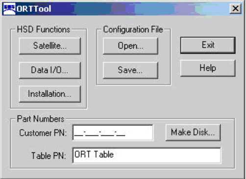
Page 2–33
18 September 2007
SYSTEM DESCRIPTION, INSTALLATION, AND MAINTENANCE MANUAL
eNfusion™ HSD-128 High-speed Data Terminal
2. In the Part Numbers text boxes, type in a Customer PN (required) and Table PN
(optional – default is ORT Table).
Note: The Part Numbers are used to identify the ORT configuration file. The
Customer PN is a required field because of ARINC Data Loader file
requirements. If your organization does not require this information, fill in
the field the Customer PN fields with any combination of numbers or
letters.
Note: The optional Table PN is a customer comment field displayed from within
the equipment's maintenance menu; it is not a required field.
3. Click Satellite.
The Satellite Information dialog box appears with system defaults showing in
the satellite names and positions data fields.
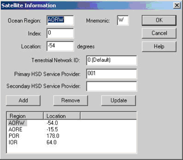
Page 2–34
18 September 2007
SYSTEM DESCRIPTION, INSTALLATION, AND MAINTENANCE MANUAL
eNfusion™ HSD-128 High-speed Data Terminal
4. In the satellite-location-information text boxes (Ocean Region, Index, Location,
and Mnemonic), modify the data for a satellite (AORE, AORW, IOR, and POR)
as required.
Note: In the Index text box, type in a unique number from 0 to 7. This index
value references the selected satellite entry’s position with the
unit’s tables.
5. In the Service Provider Information text boxes:
• Leave the Terrestrial Network ID as the default value.
Note: Terrestrial Network ID specifies which telephone network to use; at
the time of printing, the Terrestrial Network ID is not required and must
be left as the default value.
• In the Primary HSD Service Provider text box type the valid LES access code
of your primary Inmarsat Swift64 Service Provider.
• In the Secondary HSD Service Provider text box, enter the same LES access
code of your secondary Inmarsat Swift64 service provider. The Primary and
Secondary HSD Service Provider ID codes must be identical.
Note: In both the Primary and Secondary HSD Service Provider text box,
enter a valid LES access code. Both the Primary and Secondary
Service Provider fields may contain the same ID or LES access code
as at the time of printing, the Inmarsat Network does not support
Secondary Service Providers.
6. Modify the Satellite Information configuration by doing one of the following:
• Click Add to create a new entry in the satellite list field.
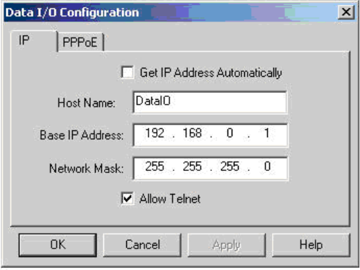
Page 2–35
18 September 2007
SYSTEM DESCRIPTION, INSTALLATION, AND MAINTENANCE MANUAL
eNfusion™ HSD-128 High-speed Data Terminal
• Click Remove to delete selected satellite entries from the
satellite list field.
• Click Update to change the data values of a satellite selected from the
existing list (the selected satellite appears highlighted).
Note: If the required data fields are not completed correctly, an error
message appears indicating incomplete or incorrect field entries.
Follow the instructions provided in the system error messages and
re-try the step.
7. Repeat steps for each satellite that requires new or revised data.
8. Click OK.
You return to the main dialog box of the HSD ORT Tool.
9. Click Data I/O.
The Data I/O Configuration dialog box appears. The Data I/O dialog box has
two, tabbed property sheets: IP and PPPoE.
10. If applicable, select the Get IP Address Automatically check box.
Note: If Get IP Address Automatically is selected, BASE IP Address and
Network Mask data is not required.
11. If required, in the IP property sheet text boxes, enter the IP addressing information
(Host Name, Base IP Address, and Network Mask) that applies to your system
configuration.
12. If applicable, select the Allow Telnet check box.
Note: Telnet provides remote monitoring and maintenance of devices using a
password-protected, terminal-emulation-program session over TCP port
23 (the Telnet Port). Selecting the Allow Telnet check box enables
remote access to the HSD using Telnet over the Ethernet port. Clearing
the Allow Telnet check box disables this remote functionality.
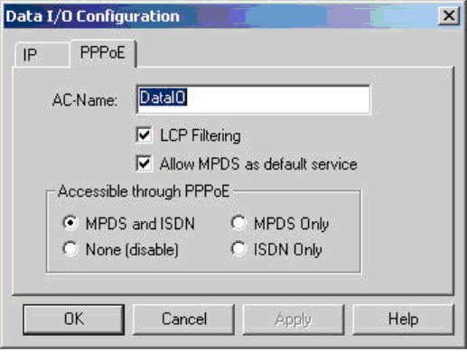
Page 2–36
18 September 2007
SYSTEM DESCRIPTION, INSTALLATION, AND MAINTENANCE MANUAL
eNfusion™ HSD-128 High-speed Data Terminal
13. Click the PPPoE tab.
The PPPoE property sheet appears.
14. In the AC-Name text box (Access Concentrator Name), type the name of the
Access Concentrator used by the PPPoE client to differentiate between multiple
PPPoE devices.
Note: The “AC-Name” is the “name of the HSD unit’s Data I/O card” that is used
to direct PPPoE communications to a specific Data I/O card of an HSD
installed on a Local Area Network. When configuring Multi-Channel HSD
systems, use the naming convention described in Table 2–7.
The AC-Name is used to identify the Data I/O cards of HSD and HSD-X
units installed on a Local Area Network. If the AC-Name text box is left
blank, all of the installed HSD/HSD-X units will respond to a PC’s request
for a connection. With each unit specifically identified by a unique
AC-Name, connections are managed through the controlled distribution
of connection requests.
Using the AC-Name to identify each unit’s Data I/O card is particularly
useful in the following reasons:
• To direct communication traffic to a specific unit to leave the other units
installed on the network free to handle different service types. For
example, direct all MPDS traffic to a specific HSD-X unit so that the
HSD transceiver channels are available for ISDN data or voice calls.
• To specify the distribution of connections using the AC-Name, so that
the connection requests are managed effectively to ensure faster and
more efficient connection start ups.
• In Multi-Channel HSD networks, to direct connection requests using
the AC-Name identifier manages call requests so that multiple
connection requests (from different computers on the network) are not
sent simultaneously to the same unit, which could lead to call failure.
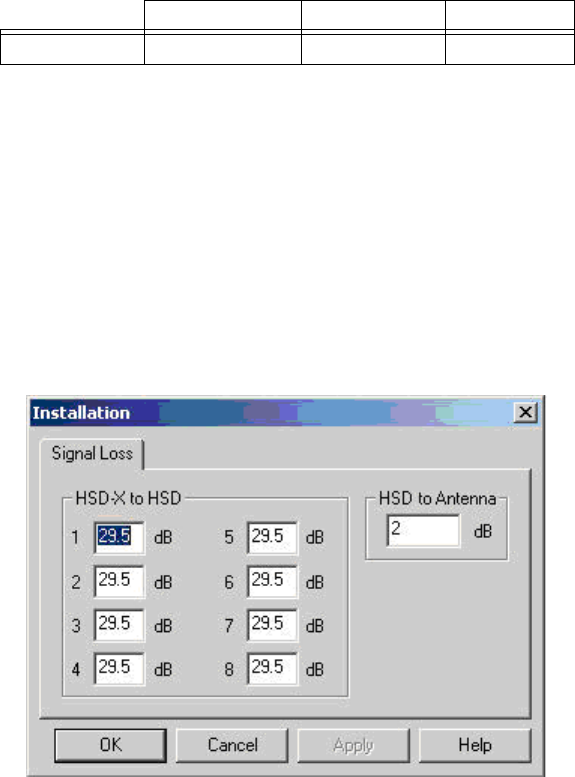
Page 2–37
18 September 2007
SYSTEM DESCRIPTION, INSTALLATION, AND MAINTENANCE MANUAL
eNfusion™ HSD-128 High-speed Data Terminal
15. Select or clear the LCP Filtering and Allow MPDS as default service check boxes
as required.
16. In the Accessible through PPPoE field, select the appropriate service option
(MPDS and ISDN, MPDS Only, None-disable, or ISDN Only).
17. Click OK.
You return to the main screen of the HSD ORT Tool.
18. Click Installation.
The Installation dialog box, Signal Loss tab sheet appears.
19. In the HSD-X to HSD text boxes, enter the Signal Loss values for each HSD-X
unit installed in the HSD system.
Note: The installer determines this value. Refer to "Installation" on page 3-1 for
more information.
20. In the HSD-to Antenna Loss text box, enter the installation-specific HSD to
Antenna Loss value.
Note: The installer determines this value (minimum of 1 dB and maximum of
2.5 dB).
21. To exit the Installation dialog box and return to the main ORT Tool menu, click
OK. Clicking OK applies the all changed or left as default values in the Installation
dialog box, Signal Loss tab fields.
Table 2–7. DATA I/O Naming Convention for AC-Name
HSD HSD-X #1 HSD-X #2
AC-Name DataIO (default) DataIO-1 DataIO-2
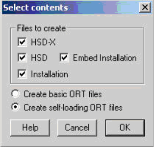
Page 2–38
18 September 2007
SYSTEM DESCRIPTION, INSTALLATION, AND MAINTENANCE MANUAL
eNfusion™ HSD-128 High-speed Data Terminal
(2) Saving the ORT file
To save the ORT file:
1. Click Save.
A Save as dialog box appears.
Note: Save a copy of the configuration file for back up and future reference.
2. In the File name text box, type the name of the configuration file.
3. Click Save.
You return to the main screen of the HSD ORT Tool.
(3) Loading the ORT
To create a disk to load the ORT:
1. Click Make Disk.
Note: If the configuration file is incomplete or contains invalid data, an error
message appears.
If an error message appears:
• Ensure that all required fields have valid data entered
• Save the configuration file
• Click Make Disk again
The Select contents dialog box appears.
The Files to create area of the Select contents dialog box contains four file
creation options. The Select contents dialog box also provides two options for
creating files: basic ORT files and self-loading ORT files. All of the Select content
options are described in Table 2–8.
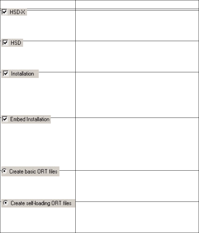
Page 2–39
18 September 2007
SYSTEM DESCRIPTION, INSTALLATION, AND MAINTENANCE MANUAL
eNfusion™ HSD-128 High-speed Data Terminal
The system prompts you to select a destination.
2. Select the appropriate destination to create the disk, and then click OK.
The HSD ORT Tool creates the disk copy of the configuration file. A message
appears confirming that the disk has been created successfully.
3. After completion of making the disk, click Exit to close the ORT Tool.
After completing the configuration of the ORT, load the ORT disks to each HSD
or HSD-X unit as described in the next section.
(4) Loading ORT Files
This section describes how to load both basic and self-loading ORT files.
Table 2–8. Description of Select Contents Dialog Box Options
Option Description
Selecting the HSD-X option creates an ORT
file for HSD-X transceivers. The format of the
basic file is HSDX.ORT. The format for a
self-loading file is HSDXORT.exe.
Selecting the HSD option creates an ORT file
for HSD transceivers. The format of basic file
is HSD.ORT. The format of a self-loading file is
HSDORT.exe.
Selecting the Installation option creates an
ORT files containing the installation
configuration information. This file is loading
into the HSD transceiver only. The format of a
basic installation file is INST.ORT. The format
for a self-loading file is INSTORT.exe.
Selecting the Embed Installation option
includes the Installation configuration data in
the HSD ORT file. Use this option to create a
single, HSD ORT file that contains both the
HSD ORT and Installation configuration files
so that they do not have to be loaded
separately.
Selecting the Create basic ORT files option
generates ORT files that are loading using the
HSD Software Load Application,
ADT_LOAD.exe (PN 1110-SW-1021).
Selecting the Create self-loading ORT files
option generates ORT files that are
self-loading, executable files that contain the
ORT configuration data.
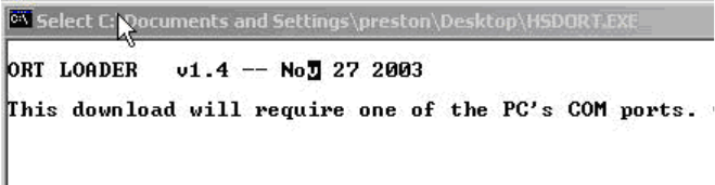
Page 2–40
18 September 2007
SYSTEM DESCRIPTION, INSTALLATION, AND MAINTENANCE MANUAL
eNfusion™ HSD-128 High-speed Data Terminal
(a) Loading Self-loading ORT Files
Self-loading ORT files have the HSD software load application embedded in the
file. Self-loading ORT files are executable. Opening the file executes the software
load application.
To load self-loading ORT configuration files onto an HSD or HSD-X unit:
1. Remove power from the system.
2. Connect a computer to the maintenance port of the HSD or HSD-X (Refer
to "Test and Fault Isolation" on page 4-1 for cabling and connection details.)
3. Turn on the computer.
4. Apply power to the unit.
5. Close all other applications running on the computer (especially programs
that use the serial COM port, e.g. HyperTerminal). The ORT load program
may not execute successfully if other programs are running.
6. Open the self-loading ORT configuration file.
The ORT Loader application window appears.
7. To load the self-loading, ORT configuration files, follow the directions as
indicated by the ORT Loader application.
The ORT Loader application loads the software to the unit connected to the
computer via the selected COM port. When the software load is complete,
the window closes.
(b) Loading Basic ORT Files
When loading a basic ORT file that does not have the self-loading application
embedded, load the file using the HSD serial loader, ADT_LOAD.exe (PN
1110-SW-1021).
Note: HSD ORT configuration files must be loaded into the HSD transceiver.
HSD-X ORT configuration files must be loaded into each of the
Multi-Channel HSD-X units installed on the system. The IP addresses are
automatically incremented.
To load basic ORT configuration files onto an HSD or HSD-X unit:
1. Remove power from the system.
2. Connect a computer to the maintenance port of the HSD or HSD-X (Refer
to "Test and Fault Isolation" on page 4-1 for cabling and connection details.)
3. Turn on the computer.
4. Apply power to the unit.

Page 2–41
18 September 2007
SYSTEM DESCRIPTION, INSTALLATION, AND MAINTENANCE MANUAL
eNfusion™ HSD-128 High-speed Data Terminal
5. Close all other applications running on the computer (especially programs
that use the serial COM port, e.g. HyperTerminal). The load program may
not execute successfully if other programs are running.
6. Start the HSD Software Load program (ADT_LOAD.exe) to launch the load
program.
A DOS window opens displaying the “Load Target” menu; it shows a number
of load selection options.
7. From the “Which Target” menu:
•Type “
15” to load the ORT file to an HSD unit.
•Type “
16” to load the ORT file to an HSD-X unit.
8. Press Enter.
The load application prompts you to type in a filename.
9. Type the appropriate filename for the software being loaded to the unit, and
then press Enter.
The application prompts you to select a COM port.
10. Select the COM port on your computer connected to the HSD.
11. Type the appropriate COM port (1 or 2—typically 1), and then
press Enter.
12. To start the load, press Enter.
Communication with the HSD transceiver is established. The following
screen appears. A percentage (%) progress indicator appears on the screen
showing load status. Once the load is complete, a confirmation message
briefly appears on the screen indicating that the file has been successfully
loaded. The DOS window then closes and the unit resets.
HSD/HST LOADER Vx.x -- Mon Mar 24 12:12:17 2003
which target ?
0 = control processor
1 = channel card #1
2 = channel card #2
3 = HPA application
4 = data i/o card
5 = HPA application with manual setup
6 = HPA application plus boot with manual setup
7 = HPA application plus boot
8 = channel card #1 boot code
9 = channel card #2 boot code
11 = channel card #1 pic code
12 = channel card #2 pic code
13 = HCM application
14 = HST ORT
15 – HSD ORT
16 – HSD-X ORT
?

Page 2–42
18 September 2007
SYSTEM DESCRIPTION, INSTALLATION, AND MAINTENANCE MANUAL
eNfusion™ HSD-128 High-speed Data Terminal
HSD/HST LOADER Vx.x – [Date]
which target ?
0 = control processor
1 = channel card #1
2 = channel card #2
3 = HPA application
4 = data i/o card
5 = HPA application with manual setup
6 = HPA application plus boot with manual setup
7 = HPA application plus boot
8 = channel card #1 boot code
9 = channel card #2 boot code
11 = channel card #1 pic code
12 = channel card #2 pic code
13 = HCM application
14 = HST ORT
15 = HSD ORT
16 = HSD-X ORT
? File name which contains the firmware image? This download will require
one of the PC's COM ports. (1, 2, etc) [1] ?
Connect COM1 of this PC to the maintenance port of the data terminal.
Hit <ESC> to abort, or <ENTER> to proceed
Establishing communication to the data terminal -- DO NOT CYCLE THE POWER!!
Hit ESC to abort.
DATA TERMINAL APPARENTLY READY TO ACCEPT PROGRAM
switching to 57.6 kbaud
loading c:\ort\hsd.ort
67% 100%
DATA TRANSFER COMPLETE -- 0 SECONDS
dio state 1DATA TRANSMITTED: 1506 BYTES CHECKSUM = 13D9FHSD/HST LOADER
Vx.x – [Date]
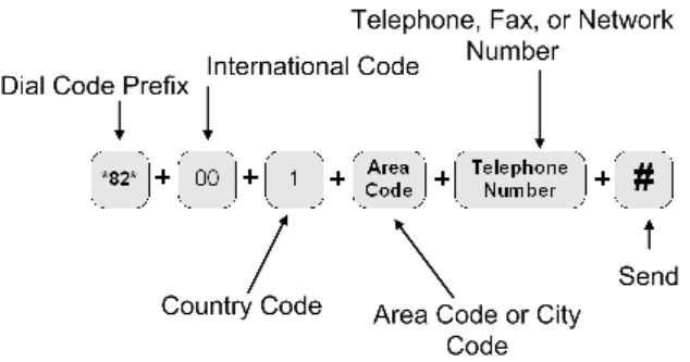
Page 2–43
18 September 2007
SYSTEM DESCRIPTION, INSTALLATION, AND MAINTENANCE MANUAL
eNfusion™ HSD-128 High-speed Data Terminal
4. Using the HSD System
This section describes how to place voice and fax calls using the ISDN interface of the HSD
SATCOM system.
A. Placing Voice and Fax Calls
Placing voice and fax calls using the HSD system are similar to placing an international
telephone call or entering a telephone number for dial-up networking data calls. Like
international telephone numbers, the HSD “dialing-number-sequence” includes different
“routing” components or codes. Figure 2–4 illustrates the required order of the dialing
components.
Figure 2–4. HSD Dialing-Sequence Components
Each dialing sequence component serves a different routing function:
• Dial Code Prefix:
Use service-specific dial code prefixes when sending fax or using analogue modems,
or for overriding system defaults to force the system to request a specific service type.
The illustration uses the dial code prefix for 3.1 KHz audio service type (*82*). (See
Table 2–9.)
• International Access Code:
The international access code for all airborne equipment is 00. However, when calling
the aircraft during ground-to-air calls, use the international code of the ground location
where the call is originating from.
• Country Code:
Public Switch Telephone Network (PSTN) number assigned to the country of your call
destination. (Example: “1” is the Country Code for North America.)
• Area Code (and City Code, if applicable):
PSTN routing number assigned to the area (and if applicable, city) of your
call destination.

Page 2–44
18 September 2007
SYSTEM DESCRIPTION, INSTALLATION, AND MAINTENANCE MANUAL
eNfusion™ HSD-128 High-speed Data Terminal
•# (SEND):
Pressing # (or entering # at the phone number field on data devices) signals the
system to “send” the call. Certain devices using the HSD system may not have the
functionality to insert the # symbol at the end of the dialing sequence. For those
devices, additional Dial Code Prefixes are required to override the “send” command
requirement. Refer to Table 2–10 for more information.
Note: For more information on using the HSD transceiver for voice and fax, refer to the
HSD User Guide (MN-1110-10048).
(1) Dial Code Prefixes
Although the system automatically selects the appropriate service types on outgoing
calls for ISDN devices, a Dial Code Prefix is required to send fax, identify an analogue
modem, or force the system to override the system defaults to select a specific service
type. (See Table 2–9.)
The system requires the Dial Code Prefix *82* for sending fax or when using analogue
modems; it forces the system to request the required 3.1 kHz audio service from the
Inmarsat Satellite Communications Network. If required, use the Dial Code Prefixes
to override the system defaults for selecting specific service types. Dial Code Prefixes
for all service types require a “¿” before and after the code number.
Other Dial Code Prefixes provide system overrides required if you are using either
devices that cannot add a # symbol to the dialing string or devices that are slow dialing.
Table 2–10 provides a description of the additional Dial Code Prefixes used for system
overrides. Table 2–6 provides a list of the LES and their associated codes available.
Table 2–9. Dial Code Prefixes for Forcing Service Type Selection
Service Type Service Description
Dial Code Prefix
(Forces Service
Selection)
Speech 64 kbps High-Speed Voice *81*
3.1 kHz audio Fax, Analogue Modem, STU-III *82*
56 kbps data High-Speed Data *83*
64 kbps data High-Speed Data *84*
4.8 kbps speech Mini-M Voice (Swift64 Low
Speed Voice)
*80*

Page 2–45
18 September 2007
SYSTEM DESCRIPTION, INSTALLATION, AND MAINTENANCE MANUAL
eNfusion™ HSD-128 High-speed Data Terminal
Note: When using the System Override Dial-Code-Prefixes do not press “¿” before
or after the Dial Code Prefix as with other dial code prefixes.
(2) Mobile-to-Mobile Communication
The HSD provides a two-way link for mobile-to-mobile (aircraft-to-aircraft)
communication.
Using mobile-to-mobile calling requires additional information. You need to know the
IMN of the device or service on the aircraft you are calling. If your service provider
does not support Inmarsat’s Single Network Access Code (SNAC) 870, you also need
to know which Satellite Ocean Region that the aircraft you are calling is logged on to.
Table 2–11 lists the SNAC code and the Satellite Ocean Regions Region Numbers.
Table 2–10. Dial Code Prefixes for System Overrides
Reason for Override Dial Code
prefix Example Dialing Sequence
Use this Dial Code Prefix to
override the default LES
configured in the system.
This Dial Code Prefix signals the
system to override the default
LES and use the selected LES
instead. (See Table 2–6.)
901 + LES
CODE
901 + LES CODE +
International Code + Country
Code + Area Code + Telephone
Number + #
901 + 002 + 00 + 1+ 613
+5551212 + #
Use with devices that cannot
produce or add a “# “character to
end the dialing sequence.
This Dial Code Prefix signals the
system to send the call after a
specified delay in user input
when the # symbol cannot be
entered.
902 902 + International Code +
Country Code + Area Code +
Telephone Number
902 + 00 + 1+ 613 + 5551212
Use with slow dialing devices
that cannot produce or add a “#
“character to end the dialing
sequence.
This Dial Code Prefix signals the
system to send the call after a
specified delay in user input.
903 903 + International Code +
Country Code + Area Code +
Telephone Number
903 + 00 + 1+ 613 + 5551212
Table 2–11. Satellite Ocean Region Codes
Satellite Ocean Region Ocean Region Number
Single Network Access Code 870
Atlantic Ocean Region East (AOR-E) 871
Atlantic Ocean Region West (AOR-W) 874
Pacific Ocean Region (POR) 872
Indian Ocean Region (IOR) 873
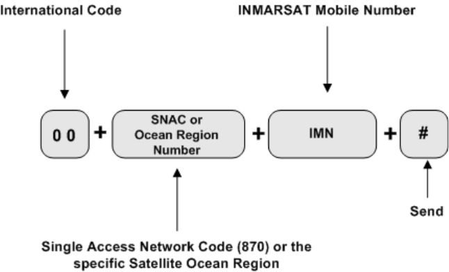
Page 2–46
18 September 2007
SYSTEM DESCRIPTION, INSTALLATION, AND MAINTENANCE MANUAL
eNfusion™ HSD-128 High-speed Data Terminal
If SNAC is unsupported, use the Ocean Regions Number that the aircraft (based on
its projected flight path) is probably logged on to. If the call fails to connect to the
aircraft, re-try the call using an alternate Ocean Region Number.
Figure 2–5 illustrates the Mobile-to-Mobile dialing sequence.
Figure 2–5. Mobile-to-Mobile Dialing Sequence
B. Using Data Connections
This section provides a basic overview of the requirements for making data connections
using the HSD transceiver. Refer to the HSD Transceiver User’s Guide (MN-1110-10048)
for detailed instructions on creating and configuring HSD dial-up networking connections.
(1) Mobile ISDN versus MPDS
Deciding which service type to use depends how you intend on using your data
connections.
For surfing the Web (with high turnover of pages and graphics), video conferencing,
video streaming, and large file transfers, Mobile ISDN is faster and more efficient.
However, service charges for Mobile ISDN are time-based (based on the length of
your total connection time).
MPDS provides a cost-effective solution for user applications that involve intermittent
interaction or transmission of data, such as e-mail, database queries, and connectivity
to IP/LAN and intranets.
MPDS also has an “always on” advantage over Mobile ISDN. Service charges for
MPDS are based on the number of data bits transmitted over the system—not on the
length of your connection time.
(2) Connecting to Inmarsat Mobile ISDN Service
The transmission of data over satellite networks differs from land-based ISDN
applications. Factors inherent in satellite communications (signal fading, latency, and
transmission blockages) can cause data transit delays and bit errors.
Page 2–47
18 September 2007
SYSTEM DESCRIPTION, INSTALLATION, AND MAINTENANCE MANUAL
eNfusion™ HSD-128 High-speed Data Terminal
Because of these challenges, it is sometimes necessary to optimize the system to
achieve peak performance over the satellite network.
ISDN protocols are not designed specifically for use over satellite communication
networks. To improve data transfer rates most ISDN protocols require minor
adjustments. For best results, consider how the ISDN protocol you intend to use sends
data over the network. Adjust the configuration taking into account the unique
operating environment of satellite network communication.
As examples, consider the protocols TCP/IP (over PPP) and V.120. As a basic
protocol, PPP operates under the networking protocol TCP/IP. PPP has error checking
properties but does not offer flow control.
TCP/IP is flexible and designed to run over different networks—including the Internet
(which like satellite networks experiences high transit delays). When used together,
PPP and TCP/IP protocols perform well over the Inmarsat network.
Improve the performance of TCP/IP (over PPP) for Mobile ISDN by changing the
default parameters. Increase the maximum size of data allowed in transit at one time
to a value up to approximately 255,552 bytes.
The protocol V.120 includes error correction and flow control applications. Flow control
limits the amount of data that can be in transit at any one time and waits for
acknowledgment of receipt from the other end of the connection before sending more
data.
The default parameters of V.120 limit the maximum transit size of the data package
to approximately 1764 bytes—causing poor performance results over satellite ISDN
networks. Improve the performance of V.120 over Mobile ISDN by changing the
default parameters. Increase the maximum size of data allowed in transit at one time
to a value up to approximately 8000 bytes. (Some applications of V.120 permit the
user to change the “window size”.)
When choosing an ISDN protocol for satellite ISDN networks, consider a flexible
solution that allows for modifications to the operating parameters to suit the unique
environment of satellite communications.
Both the HSD ISDN and Ethernet interfaces support connections to Inmarsat’s Mobile
ISDN service. Ethernet is available for HSD transceivers, PNs 1110-A-0150 and
1110-A-0160 and HSD transceivers with Service Bulletin 1110-SB-0004
accomplished. All HSD-X transceivers support the Ethernet interface.
(a) Using the ISDN Interface
The basic requirements for using the HSD ISDN interface to access Swift64
Mobile ISDN services over the satellite network are listed below:
• A EURO ISDN terminal adapter or router
• An account with an Inmarsat Service Provider
• A computer
• Dial-up Networking capabilities
The following sections describe the three main components required for Swift64
Mobile ISDN service using the ISDN interface (terminal adapters – ISDN
modems, ISDN protocols, and ISDN line).
Page 2–48
18 September 2007
SYSTEM DESCRIPTION, INSTALLATION, AND MAINTENANCE MANUAL
eNfusion™ HSD-128 High-speed Data Terminal
1. Terminal Adapters—ISDN Modem
Terminal adapters are ISDN devices that function similarly to a modem; they
dial and answer calls, and receive and transmit data. They are also referred
to as TA’s, ISDN cards, or ISDN modems.
Note: The HSD works with Euro S/T ISDN terminal adapters. Inmarsat
Swift64 Mobile ISDN service and the HSD do not support the North
American ISDN variant.
2. ISDN Protocols
Terminal adapters use ISDN protocols to format data between the ISDN line
and the user’s computer.
The HSD supports most ISDN protocols that run over a B channel on an ISDN
line; however, it does not actually implement any of these protocols. The
operating system of the user’s computer implements the protocols.
3. ISDN Line
This ISDN satellite link acts similarly to ISDN landline providing the same
service, but it supports only a single B channel and emulates the D channel.
The B channel transmits data the same as an ISDN landline; it sends data at
64 kbps with full duplex. The MES translates the 16 kbps D Channel into an
Inmarsat Mobile ISDN signaling system.
Despite the differences between landline ISDN and the Inmarsat Mobile ISDN
link, most ISDN applications run successfully over the Inmarsat network.
(b) Using the Ethernet Interface for Inmarsat Mobile ISDN
HSD transceivers with a Data I/O Type 2 Card (PNs 1110-A-0150, 1110-A-0160
and HSD transceivers with service bulletin 1110-SB-0004 accomplished) and all
HSD-X transceiver extensions support the
Ethernet interface.
The basic requirements for using the HSD Ethernet interface to access Swift64
Mobile ISDN services over the satellite network are listed below:
• A PPPoE compatible router—optional devices (e.g. routers) must be PPPoE
compatible
• An account with an Inmarsat Service Provider
• A computer with PPPoE driver installed—a PPPoE driver is the protocol most
commonly used by Digital Subscriber Line (DSL) devices; it establishes the
connection of the session and the exchanges of PPP frames over Ethernet.
• Dial-up Networking capabilities
(3) Connecting to Inmarsat MPDS
The connection requirements for MPDS service over the satellite network differ
depending on whether you access the system through an Asynchronous Serial
(RS-232) or Ethernet (10BASE-T) physical connection.
(a) Using the RS-232 Interface
To make an MPDS connection using the HSD RS-232 port requires the following:
Page 2–49
18 September 2007
SYSTEM DESCRIPTION, INSTALLATION, AND MAINTENANCE MANUAL
eNfusion™ HSD-128 High-speed Data Terminal
• An RS-232 cable (Asynchronous Serial)
• An activated account with an Inmarsat Service Provider that supports MPDS
services
• A computer with an available COM port
• Dial-up Networking capabilities
When operating MPDS over the RS-232 port, no external connecting devices
are required. The channel card in the HSD acts as a “modem” and responds to
modem “AT” commands.
In order to make an MPDS over RS-232 connection, you need to select a
standard modem on your computer to direct the data traffic to the PC COM port
connected to the RS-232 MPDS port on the HSD.
(b) Using the Ethernet Interface
HSD transceivers with a Data I/O Type 2 Card (PNs 1110-A-0150, 1110-A-0160
and HSD transceivers with service bulletin 1110-SB-0004 accomplished) and all
HSD-X transceiver extensions support the Ethernet interface.
Connections using MPDS over the HSD Ethernet port require the following:
• A Point-to-Point Protocol over Ethernet (PPPoE) driver installed—a PPPoE
driver is the protocol most commonly used by Digital Subscriber Line (DSL)
devices; it establishes the connection of the session and the exchanges of
PPP frames over Ethernet.
• An activated account with an Inmarsat Service Provider that supports MPDS
services
• A computer with an Ethernet port
• Dial-up Networking capabilities/Web browser
• Optional devices (e.g. router) must be PPPoE compatible
(c) Optimizing the System for MPDS
To optimize your system for MPDS:
• Reduce the amount of unnecessary traffic. Ensure that the router
configuration disables unnecessary Local Area Network (LAN) messages.
• Increase the window size in TCP/IP.
• Use DNS caching and Web caching. When using DNS and Web caching,
the server only retrieves from the Internet IP addresses and Web pages not
stored in the server cache.
Note: DNS caching and Web caching is effective when using a LAN
configuration on the aircraft. For stand-alone computers, use a
personal Web browser cache.
To optimize your e-mail client when using MPDS:
• Compress attachments (zip files)
• Under Tools, in the Options of your e-mail client (e.g. Outlook®, Eudora®)
customize the settings for MPDS based on the recommendations below:
Page 2–50
18 September 2007
SYSTEM DESCRIPTION, INSTALLATION, AND MAINTENANCE MANUAL
eNfusion™ HSD-128 High-speed Data Terminal
• Disable the read receipt option
• Send messages in text format not in HTML format and disable signatures
to reduce message size
• Disable the “automatic download of message when in viewing
panel” feature
• Increase the time period for automatic mail checks to reduce traffic
• Use IMAP4 mail protocol to allow for header retrieval only
Note: Disable the “Save copy of send messages in the ‘Sent Items’
folder” option.
(4) Bonding Channel Cards in Two-Channel Card Systems
This section provides, as an example, detailed instructions on how to make bonded
calls with a two-channel card HSD transceiver using a DIVA T/A ISDN modem.
Bonded calls are possible with HSD transceivers that have two channel cards
installed. Bonded calls utilize both 64 kbps channels to provide a single 128 kbps data
channel. The terminal adapter or router places two separate calls to combine the data
transfer over both channels.
Although bonded calls provide a single 128 kbps channel, the actual link capacity is
application and protocol dependant. Throughput on a Multilink PPP TCP/IP
connection is typically 80 to 90 % of the link capacity (running Windows 2000®).
The system can only make internally bonded calls if both channels are available. If
another device is using one of the B Channels, then the data call proceeds—but as
a single channel call.
If a bonded call is in progress, (using both B channels) the system is busy and denies
all other calls until a channel is free.
In Multi-Channel configurations, the HSD transceiver channel cards cannot be
internally bonded together with the HSD-X channel cards installed on the system;
however, a Multi-Channel configuration, that includes an HSD-128 and two HSD-X
extensions, is capable of up to 256 kbps data throughput—with the help of an external
device such as a router or Ethernet hub.
(a) Bonding HSD Channel Cards using the ISDN Interface
If the HSD Transceiver has two channel cards, bonded calls provide the potential
for higher throughput. For bonded calls, configure the terminal adapter and
connections to use Multilink PPP as the protocol.
Note: Not all Internet service providers support Multi-link PPP. Contact your
service provider for more information.
If a bonded call is in progress, (using both B channels) the system is busy and
denies all other calls until a channel is free.
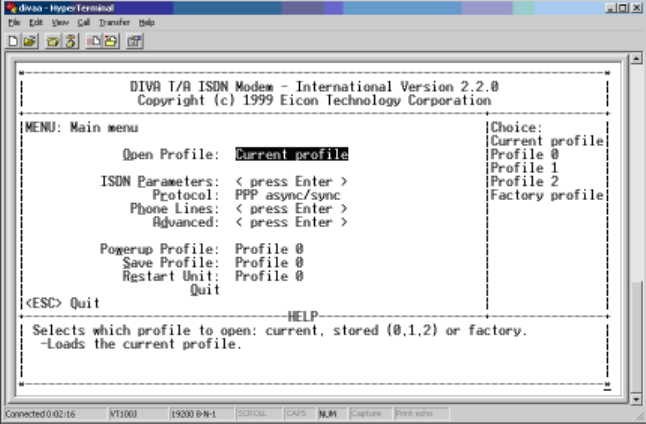
Page 2–51
18 September 2007
SYSTEM DESCRIPTION, INSTALLATION, AND MAINTENANCE MANUAL
eNfusion™ HSD-128 High-speed Data Terminal
The following is an example of a configuration for bonded calls using a DIVA T/A
for illustration purposes only. Other manufacturers’ terminal adapters may
require different or more complex configurations to configure the system for
bonded calls.
1. Using HyperTerminal, connect to the Terminal Adapter
EURO ISDN modem.
2. Type AT@MENU.
The following screen appears.
3. In the protocol field, select Multilink PPP.
The protocol field now shows Multilink PPP as the selected protocol.
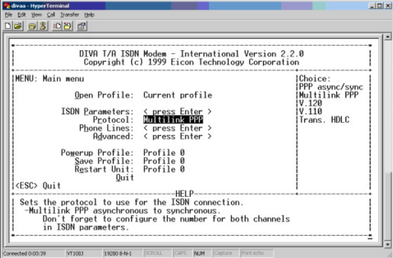
Page 2–52
18 September 2007
SYSTEM DESCRIPTION, INSTALLATION, AND MAINTENANCE MANUAL
eNfusion™ HSD-128 High-speed Data Terminal
4. When prompted, select “yes” to save the profile and then reboot your
computer.
5. Using the AT@ MENU command, confirm the settings are correct.
The Terminal Adapter is now configured to place bonded Multilink calls.
Note: If you are dialing a EURO ISDN phone number or a North American
ISDN number that has a “HUNT” group assigned, then no changes
are required to the Dial-up networking setup of the user’s computer.
The following screen illustrates a dial-up networking connection with a “HUNT”
group assigned. If a “HUNT” group number is not available, other phone numbers
may be used.
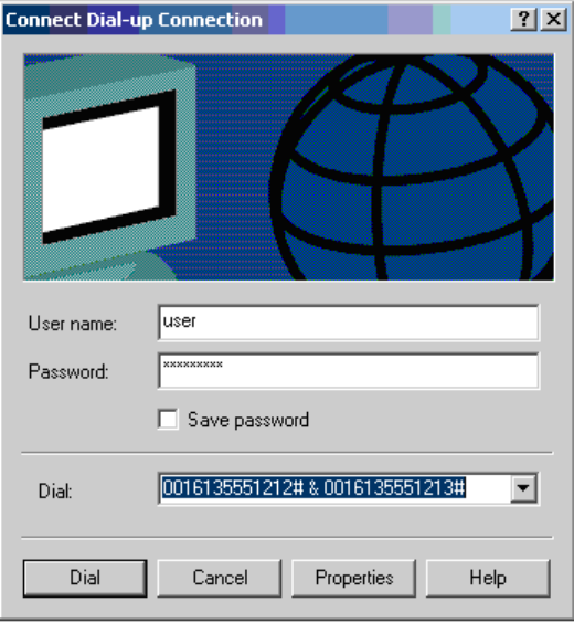
Page 2–53
18 September 2007
SYSTEM DESCRIPTION, INSTALLATION, AND MAINTENANCE MANUAL
eNfusion™ HSD-128 High-speed Data Terminal
Note: If you are dialing a North American ISDN number, both Service Profile
Identifier ISDN (SPID) numbers must be included in the dial-up networking
connection to place Multilink calls.
To configure the dial-up connection to include both SPID numbers, type in both
numbers separated by the “&” symbol.
The following screen illustrates the configuration of a Multilink connection to a
North American number.
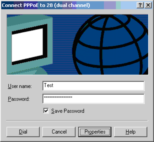
Page 2–54
18 September 2007
SYSTEM DESCRIPTION, INSTALLATION, AND MAINTENANCE MANUAL
eNfusion™ HSD-128 High-speed Data Terminal
(b) Bonding Channel Cards using the Ethernet Interface for Mobile
ISDN Service
HSD transceivers with a Data I/O Type 2 Card (PNs 1110-A-0150, 1110-A-0160
and HSD transceivers with service bulletin 1110-SB-0004 accomplished) support
the bonding of two channel cards using the HSD Ethernet interface to access
Swift64 Mobile ISDN.

Page 2–55
18 September 2007
SYSTEM DESCRIPTION, INSTALLATION, AND MAINTENANCE MANUAL
eNfusion™ HSD-128 High-speed Data Terminal
To access Swift64 Mobile ISDN services over the Ethernet interface using a
bonded two-channel-card connection
1. Create a new dial-up networking connection for two-channel Ethernet ISDN.
2. Double-click on the connection and select properties.
The PPPoE Properties Dialog box appears.
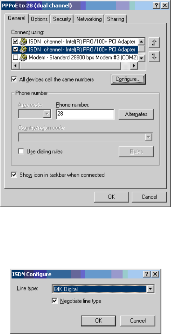
Page 2–56
18 September 2007
SYSTEM DESCRIPTION, INSTALLATION, AND MAINTENANCE MANUAL
eNfusion™ HSD-128 High-speed Data Terminal
3. From the Connect using list, select both available ISDN channels.
4. Select All devices call the same number.
5. Click Configure.
The ISDN Configure dialog box appears.
6. Select 64K Digital as the Line type.
7. Select Negotiate line type.
8. Click OK.
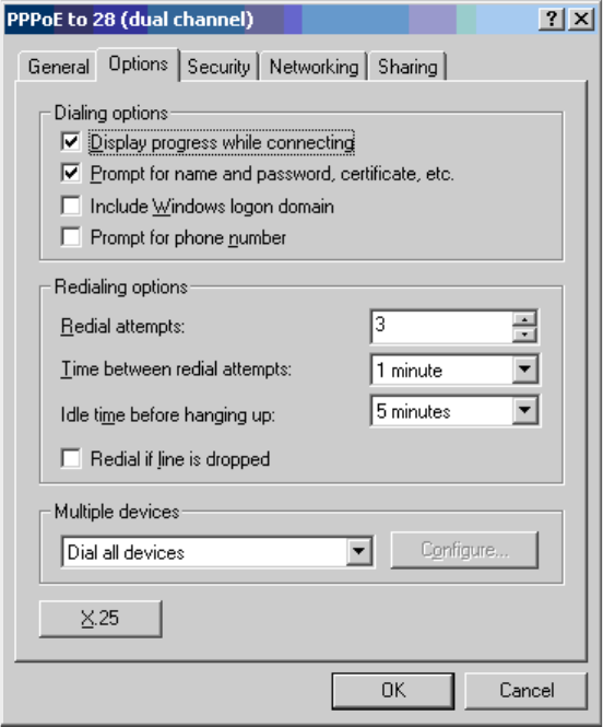
Page 2–57
18 September 2007
SYSTEM DESCRIPTION, INSTALLATION, AND MAINTENANCE MANUAL
eNfusion™ HSD-128 High-speed Data Terminal
9. Click on the Options tab.
The Options tab sheet appears.
10. From the Multiple Devices list select Dial all devices and then click OK.
(Display progress while connecting and Prompt for name and
password, certificate, etc, and Redialing options are optional.)
11. Click the Security tab.
12. In Security options, select Typical recommended settings and Allow
unsecured password.
13. Click OK.
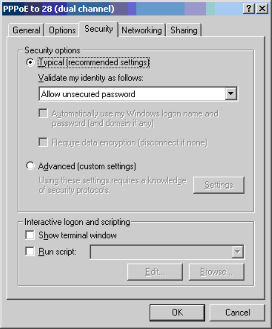
Page 2–58
18 September 2007
SYSTEM DESCRIPTION, INSTALLATION, AND MAINTENANCE MANUAL
eNfusion™ HSD-128 High-speed Data Terminal
14. Click the Networking tab.
The Networking tab sheet appears.
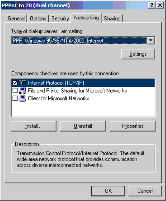
Page 2–59
18 September 2007
SYSTEM DESCRIPTION, INSTALLATION, AND MAINTENANCE MANUAL
eNfusion™ HSD-128 High-speed Data Terminal
15. Select the Internet Protocol TCP/IP.
16. Click Properties.
The Internet Protocol dialog box appears.
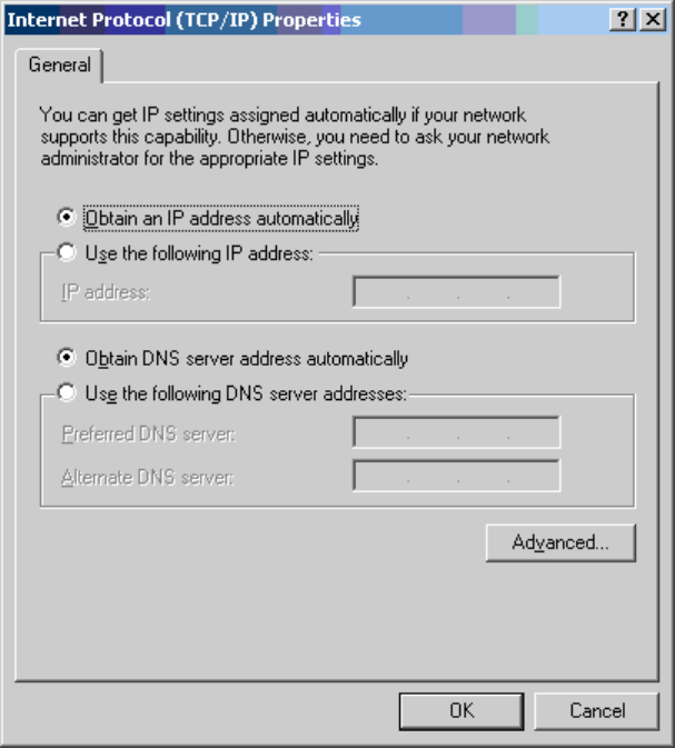
Page 2–60
18 September 2007
SYSTEM DESCRIPTION, INSTALLATION, AND MAINTENANCE MANUAL
eNfusion™ HSD-128 High-speed Data Terminal
17. Select “Obtain an IP address automatically” and “Obtain DNS address
automatically”, and then click OK.
This completes the creation of the new bonded connection for Mobile ISDN using
the Ethernet interface. Before using the connection, you need to configure the
Local Area Connection properties.
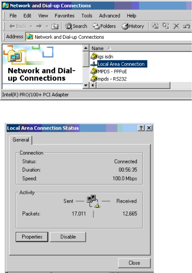
Page 2–61
18 September 2007
SYSTEM DESCRIPTION, INSTALLATION, AND MAINTENANCE MANUAL
eNfusion™ HSD-128 High-speed Data Terminal
To Configure the Local Area Connection Properties for Bonding (PPPoE):
1. In Network and Dial-up Connections, double-click on Local Area
Connection.
The Local Area Connection Status dialog box appears.
2. Click Properties.
The Local Area Connection Properties dialog box appears.
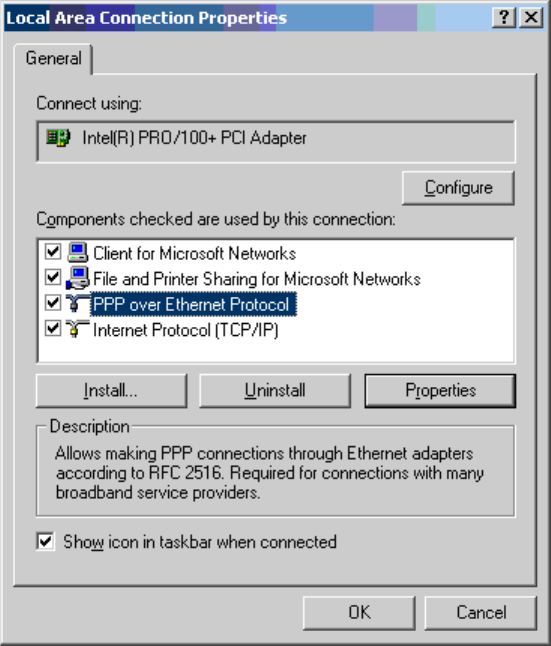
Page 2–62
18 September 2007
SYSTEM DESCRIPTION, INSTALLATION, AND MAINTENANCE MANUAL
eNfusion™ HSD-128 High-speed Data Terminal
3. Select PPP over Ethernet Protocol and then click Properties.
The PPP over Ethernet Protocol Properties dialog box appears.
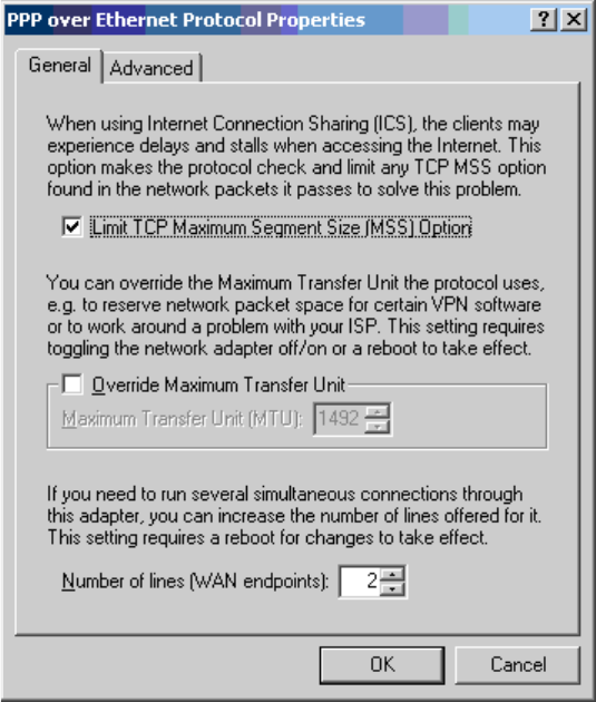
Page 2–63
18 September 2007
SYSTEM DESCRIPTION, INSTALLATION, AND MAINTENANCE MANUAL
eNfusion™ HSD-128 High-speed Data Terminal
4. On the General tab sheet, select “2” for the Number of lines (WAN
endpoints).
This completes the connection configuration for the two-channel Swift64 Mobile
ISDN over Ethernet connection. The connection is ready to use.
Page 2–64
18 September 2007
SYSTEM DESCRIPTION, INSTALLATION, AND MAINTENANCE MANUAL
eNfusion™ HSD-128 High-speed Data Terminal
Page 3–1
18 September 2007
SYSTEM DESCRIPTION, INSTALLATION, AND MAINTENANCE MANUAL
eNfusion™ HSD-128 High-speed Data Terminal
INSTALLATION
1. Introduction
This section provides general information and procedures required to install HSD transceivers
and HSD-X transceivers in Multi-Channel configurations on an aircraft. Mode-specific
installation instructions are provided in separate installation sections.
The organization of the installation information provided in this section is described below:
•General Installation
This section provides general installation information that applies to all modes and
configurations of HSD and HSD-X systems, including pre-installation instructions,
general cabling and connector requirements, information on installation kits, and
physical placement considerations.
•Section I: Stand-Alone Mode Installation
This section provides installation information specific to Stand-Alone Mode HSD
transceiver system configurations.
•Section II: Combined Mode (HCM)/Selective Mode Installation
This section provides installation information specific to Combined Mode and
Selective Mode HSD transceiver system configurations.
•Section III: Cooperative Mode Installation
This section provides installation information specific to Cooperative Mode HSD
transceiver system configurations.
•Section IV: Multi-Channel Configuration Installation
This section provides installation information specific to Multi-Channel HSD
transceiver system configurations that includes the installation of HSD-X transceiver
extension units.
If installation assistance is required, contact EMS SATCOM Product Support at the telephone
or fax numbers listed in the front matter of this manual.
Page 3–3
18 September 2007
SYSTEM DESCRIPTION, INSTALLATION, AND MAINTENANCE MANUAL
eNfusion™ HSD-128 High-speed Data Terminal
3. Pre-Installation Inspection
Before installing any HSD equipment, conduct a pre-installation inspection of all parts to
ensure that no damage occurred during transit.
Page 3–4
18 September 2007
SYSTEM DESCRIPTION, INSTALLATION, AND MAINTENANCE MANUAL
eNfusion™ HSD-128 High-speed Data Terminal
4. Unpacking and Inspecting Equipment
• Unpack the HSD/HSD-X transceiver(s) from their shipping containers.
• Verify that the part number displayed on the shipping box and equipment component
matches the model and part number ordered. If components are missing from the
shipment, contact EMS Technologies immediately and report the problem.
• Visually inspect the unit for any shipping damage. If any shipping damage has
occurred, contact the shipping carrier immediately and report the problem.
• Check the HSD/HSD-X transceiver connectors for corrosion and damage. If damage
is noted, do not apply power to the unit. Report any damage to EMS SATCOM
immediately.

Page 3–5
18 September 2007
SYSTEM DESCRIPTION, INSTALLATION, AND MAINTENANCE MANUAL
eNfusion™ HSD-128 High-speed Data Terminal
5. Cabling and Connector Requirements
This section provides general electrical installation information on power, ground, shielding
requirements, and cabling that applies to all installation modes for HSD and HSD-X
transceivers.
A. Power Requirements
The aircraft power supply provides power to the HSD transceiver. This power supply must
be +28 V dc nominal for models PN 1110-A-0001, 1110-A-0160, and 1110-A-0080. For
HSD models, PN 1110-A-0060, 1110-A-0150, and PN 1110-A-0070, and HSD-X model
PN 1110-A-0401, the power supply must be at 115 V ac, 400 Hz (nominal).
The breaker rating for the HSD assembly is based on power consumption details provided
in Table 1 Variants of Outline and Installation Diagram (1110-E-0001) presented in 225.
The power requirements for the HSD-X transceiver are listed in the notes on the HSD-X
Outline and Installation Diagram.
B. Ground Requirements
Improper grounding can potentially lead to ground loops and induced Electromagnetic
Interference (EMI) or Radio Frequency Interference (RFI). When installing an HSD or
HSD-X transceiver, follow standard grounding practices for both chassis and cabling
shields.
C. Cable Shielding and Termination
The preferred method of cable shield termination is in accordance with NEMA WC
27500:2000 and ARINC 741. ARINC Report 413A – Guidance for Aircraft Electrical Power
Utilization and Transient Protection provides more detailed information in Attachment 3-2,
Wire Shielding and Grounding Requirements and in Appendix 7.
Unless otherwise stated, all cable shields must be connected to the closest aircraft ground
at both ends of the cable as well as on both sides on any production break in the cable.
Where applicable, terminate shields with connectors via the backshell or via a pigtail with
a suitable termination to the closest aircraft ground.
General aviation cable-routing guidelines apply. Refer to Table 3–1 for detailed
information.
Note: Typically, Ethernet and ISDN cable has multiple shields; terminate each shield
separately.
Table 3–1. Cable Shielding and Termination Specifications
Cable
Function Conductor Type (Typical) Single
Point
Multiple
Point
Minimum
Conductor
Coverage by
Shield
Power Lines Single conductor, stranded N/A N/A N/A
Digital Control Twisted pair, stranded Yes 85%
Serial Data Twisted pair, stranded Yes 85%
Ethernet Data Twisted pair, stranded Yes 85%

Page 3–6
18 September 2007
SYSTEM DESCRIPTION, INSTALLATION, AND MAINTENANCE MANUAL
eNfusion™ HSD-128 High-speed Data Terminal
ISDN Data Twisted pair, stranded Yes 85%
Discrete Lines Single conductor, stranded N/A N/A N/A
RF TX and RX Coaxial Yes 95%
Definitions:
Single Point: Cable shield terminated at one end only—via a connector or suitable
crimp terminal.
Multiple Point: Cable shield terminated at both ends via a connector or suitable
crimp terminal, usually at both ends of the cable—and at both side of any production
break.
N/A: Not applicable.
Table 3–1. Cable Shielding and Termination Specifications
Cable
Function Conductor Type (Typical) Single
Point
Multiple
Point
Minimum
Conductor
Coverage by
Shield

Page 3–7
18 September 2007
SYSTEM DESCRIPTION, INSTALLATION, AND MAINTENANCE MANUAL
eNfusion™ HSD-128 High-speed Data Terminal
6. ARINC 600 Trays and Connectors
This section provides detailed information on the ARINC 600 trays provided in the HSD
Installation Kits that are used in the installation of the HSD and HSD-X transceivers.
The HSD LRU is installed in a standard, ARINC 600, 8-MCU tray. Ruggedized trays designed
specifically for installations on Helicopter aircraft are also available.
The HSD-X LRU is typically installed in a standard, 2-MCU tray. Ruggedized trays designed
specifically for installations on Helicopter aircraft are also available.
A. Installation Kits
Installation kits for HSD and HSD-X transceivers are available from EMS Technologies
Ltd. Contact EMS Technologies Sales department for more information on how to select
and order the appropriate HSD Installation Kit.
Table 3–2 lists the recommended installation kits for typical installations.
Table 3–2. HSD and HSD-X Installation Kits
Installation Kit
Name
EMS SATCOM
Part Number Description
HSD Installation Kit
AC FAN
1110-F-0120-01 Standard Installation Kit: Bottom AC
Fan Tray Assembly and ARINC
Connector (Un-pressurized
Installation)
HSD Installation Kit
DC FAN
1110-F-0120-02 Standard Installation Kit: Bottom DC
Fan Tray Assembly and ARINC
Connector (Un-pressurized
Installation)
HSD Installation Kit
HELICOPTER AC
FAN
1110-F-0120-03 Helicopter Installation Kit: Side AC
Fan Tray Assembly and ARINC
Connector
HSD-X Installation
Kit AC FAN
1110-F-0121-01 Standard Installation Kit: Fan Tray
Assembly with Bottom AC Fan and
ARINC Connectors
HSD-X Installation
Kit NO FAN
1110-F-0121-02 Standard Installation Kit: Tray
Assembly and ARINC Connectors (No
Fan)
HSD-X Installation
Kit HELICOPTER
NO FAN
1110-F-0121-03 Helicopter Installation Kit: Tray
Assembly with Isolators and ARINC
Connectors (No Fan)
HSD/HSD-X COAX
Cable Kit
1110-K-0122 Multi-Channel RF COAX Kit: Tx and
Rx Cables (33ft), Combiners, Splitters,
Isolators, and HSD-X Cables
Page 3–8
18 September 2007
SYSTEM DESCRIPTION, INSTALLATION, AND MAINTENANCE MANUAL
eNfusion™ HSD-128 High-speed Data Terminal
B. Cabling Notes
Before proceeding with the installation of the HSD transceiver, read all cabling notes
provided on the HSD System Interconnection Diagram for the applicable HSD system
operational mode.
(1) HSD Transceiver Cabling
When installing the HSD transceiver, follow the cabling requirements listed below:
• Maximum recommended cable length should not exceed 50 feet.
• LAN cables must meet flammability, TIA/EIA568-A CAT 5 requirements, and
conform to ARINC 628 specifications.
• Wire size recommendations:
• For +28 V dc HOT (BP2), +28 V dc RTN GND (BP3), 115 V ac COLD (BP7),
and Chassis GND (BP8), use 12 AWG
• For 115 V ac HOT (BP1), use 20 AWG
• Unless otherwise specified, for signaling use 22 AWG wire.
(2) HSD-X Transceiver Cabling
When installing the HSD-X transceiver in Multi-Channel Configurations, follow the
cabling requirements listed below:
• For 115 V ac HOT (BP2), use 20 AWG
• For 115 V ac COLD (BP4), use 20 AWG
• Chassis GND (BP3), use 14 AWG
(3) HSD Transceiver Coaxial Cable Loss Considerations
When installing HSD transceivers, consider the following coaxial cable loss
requirements:
•Transmit cable: Maximum loss is 2.5 dB including DLNA (typically <0.8 dB) as
per ARINC 741. In installations that use a high power relay, the high power relay
loss must be included.
•Receive cable: For HSD transceivers operating in Stand-Alone, Cooperative, and
Combined Mode installations, the minimum loss is 6 – 25 dB (including any in-line
attenuator) as per ARINC 74. For HSD-128 and HSD-X transceivers installed in
Multi-Channel Configurations, the minimum loss is 0 – 19 dB (including cables
and splitters).
Page 3–9
18 September 2007
SYSTEM DESCRIPTION, INSTALLATION, AND MAINTENANCE MANUAL
eNfusion™ HSD-128 High-speed Data Terminal
7. Mechanical Installation
This section describes the mechanical installation requirements for the HSD and HSD-X units.
The outline and installation drawings for both transceivers are provided at the end of this
section.
A. General
This section contains the information required to plan the physical placement of the HSD
and HSD-X (Multi-Channel configurations only) transceivers.
The HSD Transceiver Outline and Illustration Drawing (Sheet 1 and 2) illustrates the
physical and mechanical specifications of the HSD transceiver. The HSD-X Transceiver
Outline and Illustration Drawing (Sheet 1 and 2) illustrates the physical and mechanical
specifications of the HSD-X transceiver.
In typical aircraft installations, the HSD assembly fits into standard ARINC, 8-MCU
mounting trays. HSD-X units fit into standard, 2-MCU mounting trays. Specialized trays,
that meet the requirements for installations of both the HSD and HSD-X units on
Helicopters, are also available from EMS SATCOM.
All HSD ARINC installation trays are included in the HSD and HSD-X Installation Kits that
are available from EMS Technologies Ltd. Section Installation Kits describes the HSD and
HSD-X Installation Kits available from EMS SATCOM.
B. Physical Placement
When selecting a placement location for the HSD, and if applicable, HSD-X mounting
trays, allow for adequate spacing for the installation of the HSD assembly while providing
reasonable access for servicing. Leave a minimum gap of 0.5 inches between LRUs.
In Multi-Channel configurations, after wiring the tray(s) for HSD-X units, populate the trays
in order, starting from the first-in-line tray that is directly connected to the HSD-128
transceiver. The second HSD-X tray is connected to the first HSD-X tray as shown in
Figure 3–1. HSD-X trays are strapped to index the HSD-X units to read the appropriate
ARINC messages on the crosstalk bus (communications bus).
If an HSD-X must be removed for service, the Multi-Channel HSD system will still function,
but the remaining HSD-X units must be moved so that no empty trays are in the middle
of the series or chain. Refer to "Maintenance and Repair" on page 5-1 for more information.
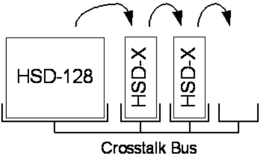
Page 3–10
18 September 2007
SYSTEM DESCRIPTION, INSTALLATION, AND MAINTENANCE MANUAL
eNfusion™ HSD-128 High-speed Data Terminal
Figure 3–1. HSD-X Physical Placement Requirements
C. Environmental Requirements
The environmental requirements that must be considered during the physical placement
of the HSD and HSD-X transceivers are based on the RTCA/DO-160D Environmental
Specifications detailed in "System Description" on page 1-1.
The standard mounting trays for the HSD and HSD-X offer a number of fan configuration
options depending on the physical placement of the LRU in the aircraft.
(1) Heating and Cooling
Refer to "System Description" on page 1-1 for a complete listing of the
RTCA/DO-160D Environmental Specifications for the HSD and HSD-X transceivers.
(a) HSD Transceivers
When selecting an installation location for the HSD transceiver, consider the
heating and cooling requirements listed below:
• Power Dissipation (DC models): 275 Watts nominal, 370 Watts maximum
• Power Dissipation (AC models): 275 Watts nominal, 385 Watts maximum
• Cooling Air: per ARINC 600
• Recommended Flow rate: 175 lbs/hr
• Pressure drop: 0.05”, ± 0.025” H2O
(b) HSD-X Transceivers
When selecting an installation location for the HSD-X transceiver, consider the
heating and cooling requirements listed below:
• Power Dissipation: 34 Watts
• Cooling Air: per ARINC 600
• Recommended Flow rate: 15.5 lbs/hr
• Pressure drop: 0.044”, ± 0.025” H2O
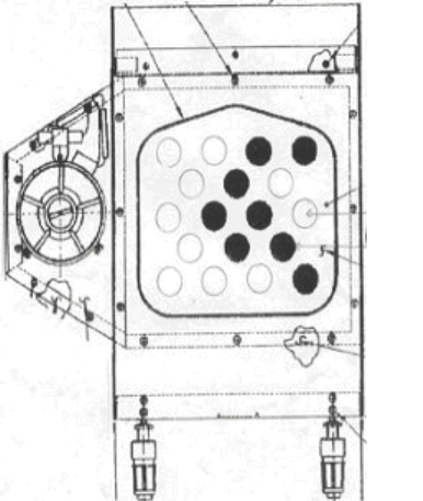
Page 3–11
18 September 2007
SYSTEM DESCRIPTION, INSTALLATION, AND MAINTENANCE MANUAL
eNfusion™ HSD-128 High-speed Data Terminal
(c) HSD Fan Tray Requirements
WARNING: Failure to install and configure the fan tray assembly as instructed
may seriously compromise the HSD’s extreme temperature
operation.
Fan tray assemblies may be shipped with or without hole-plug-buttons installed.
For adequate airflow to the HSD subassemblies, the plugs must be installed or
removed in the fan/tray configuration as illustrated in Figure 3–2. Installed plugs
are shown in black, and removed plugs are shown in white.
Figure 3–2. Fan Tray Plug Configuration
D. Chassis Grounding
The HSD and HSD-X tray-mounted assemblies must be electrically bonded to the
airframe. Ensure the mating surfaces are free from contaminants such as paints or other
non-conductive elements. Where surface preparations are insufficient to ensure a proper
bond, the use of a short, tin-coated, copper bonding strap of at least 1/4 inch wide is
recommended. The LRU and tray assemblies should provide a low impedance path of
<0.2 ohms.
Page 3–12
18 September 2007
SYSTEM DESCRIPTION, INSTALLATION, AND MAINTENANCE MANUAL
eNfusion™ HSD-128 High-speed Data Terminal
8. Electrical Installation
This section provides mode-specific installation details for HSD and HSD-X transceivers. This
section is divided into sub-sections that provide the electrical installation requirements for the
different modes of operation. The sub-sections are presented as follows:
•Section I: Stand-Alone Mode Installation
This section provides installation requirements for HSD transceivers operating in
Stand-Alone Mode.
•Section II: Combined Mode (HCM)/Selective Mode Installation
This section provides installation requirements for HSD transceivers operating in
Combined Mode (Honeywell Combined Mode) and Selective Mode.
Selective Mode is a non-standard installation and it is not a recommended mode of
operation. Selective Mode has been superseded by Combined Mode operation for
MCS series SATCOM and with Cooperative Mode operation for SAT-906 series
SATCOM. It is recommended that all systems operating in Selective Mode be
upgraded to support Combined or Cooperative Mode as applicable.
•Section III: Cooperative Mode Installation
This section provides installation requirements for HSD transceivers operating in
Cooperative Mode.
•Section IV: Multi-Channel Configuration Installation
This section provides installation requirements for HSD transceivers operating in
Multi-Channel Configurations with HSD-X transceiver extension units.
A. Section I: Stand-Alone Mode Installation
(1) Stand-Alone Mode Installations Wiring Notes
This section provides detailed information on the external interface and system
connections involved in the installation of an HSD transceiver for Stand-Alone Mode
operation.
(a) Source/Destination Identification (SDI) – Stand-Alone
Source/Destination Identification (SDI) is provided for the BSU and the HPA as
per ARINC 741 specifications. Pins marked “0” are left open-circuit and pins
marked “1” are strapped on the airframe side of the connector to the pin assigned
as “SDI Common” (TP5D). For this High Gain Antenna (HGA) HPA application,
pin TP5B (“1”) should be strapped and TP5A (“0”) should be left open.
Note: The logic for the SDI/WOW is explained in ARINC 741 Characteristic
Attachment 1-4, Note 19. This SDI/WOW logic as applied according to the
ARINC specification, where 0=open and 1=strapped to common, is the
reverse of the logic applied to all other HSD and HSD-X connectors,
Forward ID, System Config, and Data I/O Config , where 0=strapped to
common and 1=open.
(b) Maintenance Port Interface – Stand-Alone
The HSD transceiver has an RS-232 Maintenance Port interface that provides
access to a maintenance utility program for data loading, system monitoring and
testing purposes.

Page 3–13
18 September 2007
SYSTEM DESCRIPTION, INSTALLATION, AND MAINTENANCE MANUAL
eNfusion™ HSD-128 High-speed Data Terminal
Access to the HSD Maintenance Utility Program is achieved by connecting an
RS-232, VT-100 terminal (PC or Laptop operating a terminal emulation program)
to the RS-232 Maintenance Port.
The HSD Maintenance port is available at the front of the HSD and at the rear
ARINC 600 connector. Connection on the front of the HSD is accessible via a
DB25S connector for local maintenance of the unit. Remote access is provided
for cases where local access is unavailable. For remote access, install an
accessible DB9S connector in the cabin area.
Note: The front panel and remote connections to the maintenance port cannot
be used simultaneously.
Refer to "Test and Fault Isolation" on page 4-1 for information on how to connect
and use the maintenance port—including, equipment requirements, connection
and cabling requirements, software loading instructions, and configuration
details.
(c) Antenna Subsystem RF Interface – Stand-Alone
Several external RF parameters (such as cable losses and antenna gain), that
must be delimited to ensure proper operation, dictate the HSD performance
requirements. Table 3–3 defines these parameters and their expected values.
(d) WOW Pin Wiring – Stand-Alone
These Weight-On-Wheel (WOW) discretes are wired only if equivalent
information is not strapped as being available to the SDU on an ARINC 429 input
[for example, IRS or the Centralized Fault Display System (CFDS)].
WOW wiring, for the HSD, is optional for system operation as the HSD already
receives speed information for Doppler correction. However, if WOW wiring is
not wired, normal maintenance must be disabled when speed or Doppler
readings are greater than zero.
The WOW1 and WOW2 pins are either left open circuit or they are connected to
the airframe DC ground. The WOW Program Select (PGM) pin is either left open
circuit or is connected to the Forward Address Common. The three ground states,
defined for any pin are:
• OPN: Open circuit
Table 3–3. RF Parameters Definition
Parameter Min. Value (dB) Max. Value (dB)
Antenna Gain 8 17
Antenna—DLNA Loss 0.1 0.3
DLNA Gain 53 60
DLNA Noise Figure 1.5 1.8
DLNA—HSD (Rx) Loss 6 25
HSD—Antenna (Tx) Loss 1 2.5
DLNA Insertion Loss (Tx to
Antenna Port)
–0.8

Page 3–14
18 September 2007
SYSTEM DESCRIPTION, INSTALLATION, AND MAINTENANCE MANUAL
eNfusion™ HSD-128 High-speed Data Terminal
• AFG: Airframe DC Ground
• FAC: Fwd Address Common (TP7K)
Resolve any conflict between WOW1 and WOW2 by assuming the aircraft is
“in-air.” The interpretation of the state of the WOW1 and WOW2 pins is defined
by the state of the WOW program select pin. Refer to Table 3–4 for details.
1. Stand-Alone Mode Installations
Labeled as WOW1, WOW2, and WOW Program Select, these discretes are
wired only if equivalent information is not strapped as being available to the
SDU on an ARINC 429 input [for example, IRS or the Centralized Fault
Display System (CFDS)].
WOW wiring is optional for system operation in Stand-Alone Mode
installations as the HSD already receives speed information for Doppler
correction. However, if WOW wiring is not wired, normal maintenance must
be disabled when speed or Doppler readings are greater than zero.
(e) Forward and Return Address IDs – Stand-Alone
Figure 3–3 provides an example of a Forward ID address. The Forward ID is a
Hex number (example: $ABC123) that must be converted into a binary number
for strapping.
Table 3–4. WOW Pin Wiring Table
Pin Name and Location
WOW1 WOW2 PGM Aircraft Status
TP3G TP3H TP3J
AFG AFG FAC In-air
OPN AFG FAC Not valid – Default in-air
AFG OPN FAC Not valid – Default in-air
OPN OPN FAC On-ground
AFG AFG OPN On-ground
OPN AFG OPN Not valid – Default in-air
AFG OPN OPN Not valid – Default in-air
OPN OPN OPN In-air
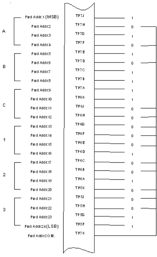
Page 3–15
18 September 2007
SYSTEM DESCRIPTION, INSTALLATION, AND MAINTENANCE MANUAL
eNfusion™ HSD-128 High-speed Data Terminal
Figure 3–3. Forward ID, Hex to Binary Conversion
Note: A pin strapped to the same potential as T7K (Forward address common)
is considered as a logical “0”, whereas an open circuit pin is considered
as a logical “1”.
MSB is the Most Significant Bit and LSB is the Least Significant Bit.
(f) Remote Status Panel – Stand-Alone (Optional)
An optional “remote status panel” may be installed in installations where the HSD
and/or any HSD-X units are located in inaccessible or remote locations. The
installation of a “remote status panel” is recommended as it provides visual
indications of each of the power, fault, and call status of each of the units.

Page 3–16
18 September 2007
SYSTEM DESCRIPTION, INSTALLATION, AND MAINTENANCE MANUAL
eNfusion™ HSD-128 High-speed Data Terminal
A “remote reset switch” for HSD transceivers can also be installed and located
with the Remote Status Panel. Figure 3–4 illustrates a typical wiring diagram for
the remote reset circuit.
Note: Cooperative and Combined Mode installations and HSD-X transceivers
DO NOT support the use of the reset function.
1. HSD Remote Reset Switch Circuit Requirements – Stand-Alone
HSD transceivers support the installation of a Remote Reset Switch circuit
as shown in Figure 3–4.
The HSD Remote Reset circuit requires less than 100 ohms between TP1K
(RESET) and MP1F(COM) to be asserted and greater than 10 kilohms to be
de-asserted (include all cable and switch contact resistance).
2. HSD Remote LED Driver Circuit Requirements – Stand-Alone
The circuit requirements for the HSD Remote Status LED drivers are shown
in Figure 3–5. Each LED driver circuit has a 200-ohm current limit resistor.
The maximum cable resistance (including the forward and return paths) must
not exceed 100 ohms to provide adequate current to the 5 volt LEDs (i.e. 10
mA minimum) at the remote status panel.
It is recommended that the installer use shielded cables to provide a level of
noise immunity.
Figure 3–4. HSD Remote Reset Circuit – Stand-Alone
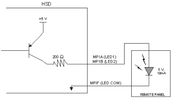
Page 3–17
18 September 2007
SYSTEM DESCRIPTION, INSTALLATION, AND MAINTENANCE MANUAL
eNfusion™ HSD-128 High-speed Data Terminal
Figure 3–5. HSD Remote LED Panel Circuit – Stand-Alone
(g) User Interfaces – Stand-Alone
To facilitate user access to the HSD interfaces, install the following connectors
in the appropriate cabin area.
Note: Although the Ethernet interface is only supported by HSD-X transceivers,
HSD transceiver models, PN 1110-A-0150 and 1110-A-0160, and other
models of HSD transceivers with service bulletin 1110-SB-0004
accomplished, consider pre-wiring the cabin for all interfaces—even when
installing an HSD transceiver that currently does not support the Ethernet
interface.
1. ISDN Interface
Install an RJ-45 interface connector in the cabin area for user connections to
the ISDN interface. RJ-45 Connector Termination Details below describes the
RJ-45 connector and cable termination.
2. RS-232 Interface (MPDS)
Install a DB9S interface connector in the cabin area for connection to the
RS-232 interface. Refer to the HSD Interconnection Drawings for pinout
designation.
3. Ethernet Data Interface
HSD transceiver models, part numbers 1110-A-0150 and 1110-A-0160
support the Ethernet interface. All other models of HSD transceivers must
have service bulletin 1110-SB-0004 (Data I/O Type 2) accomplished to
support the Ethernet interface.
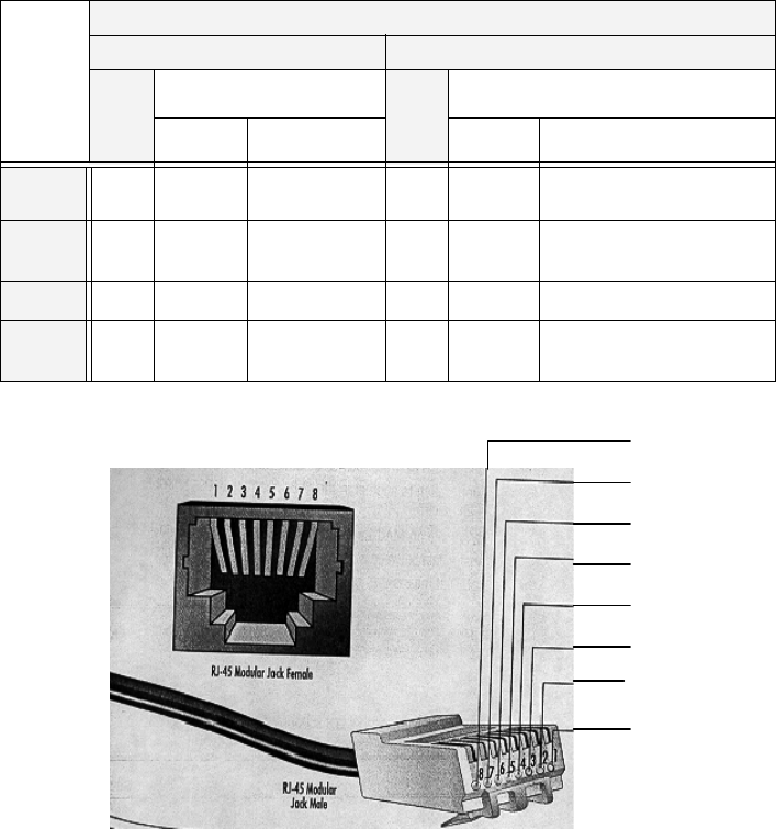
Page 3–18
18 September 2007
SYSTEM DESCRIPTION, INSTALLATION, AND MAINTENANCE MANUAL
eNfusion™ HSD-128 High-speed Data Terminal
Install an RJ-45 interface connector in the cabin area for user access to the
Ethernet interface. The next section describes the RJ-45 connector and cable
termination.
4. RJ-45 Connector Termination Details
Details relating to the RJ-45 cable terminations, required for both the ISDN
and/or 10BASE-T services, are shown in Table 3–5 and Figure 3–6.
Use LAN cables that meet flammability and TIA/EIA568-A CAT-5
requirements. Cables #922404(4 conductor) and # 922408 (8 conductor), as
supplied by Electronics Cable Specialists, are acceptable. Equivalent
substitutions from other manufacturers may be used.
Figure 3–6. RJ-45 Connector Terminator Details – Stand-Alone
Table 3–5. RJ45 Wiring Details – Stand-Alone
Signal
SERVICE
EURO ISDN Ethernet 10BASE-T
Pin
Cable
Pin
Cable
ECS Other ECS Other
RX + 3 White White/Green 3 White White/Orange stripe
RX−6 Blue Green 6 Green Orange/White stripe or
solid Orange
TX+ 4 White Blue 1 White White/Green stripe
TX−5 Orange White/Blue 2 Brown Green/White stripe or
solid Green
8
7
6
5
4
3
1
2

Page 3–19
18 September 2007
SYSTEM DESCRIPTION, INSTALLATION, AND MAINTENANCE MANUAL
eNfusion™ HSD-128 High-speed Data Terminal
5. System Configuration Pin Strapping – Stand-Alone
The HSD adjusts its configuration according to the status of several strap pins
on the rear ARINC 600 connector.
Configuration pins are assigned based on system mode configuration
selection and data input/output (I/O) requirements, as shown in Table 3–6.
Detailed pin assignment is shown in Table 3–7 and Table 3–8.
Note: The logic for the System Configuration pins is reverse to the logic
explained in ARINC 741 Characteristic Attachment 1-4, Note 19. For
System Configuration pins, 0=strapped to common and 1=open.
• Pins marked “0” are signaled by strapping to “Fwd Address
Common” (T7K).
• Pins marked “1” are signaled by an open circuit—no connection.
• Configurations resulting in all “1’s” are invalid.
6. System Mode Strap Pins Coding – Stand-Alone
The HSD must be externally strapped according to its intended operational
configuration mode. Table 3–7 illustrates the system pin strapping for all HSD
operational modes and configurations. The system pin strapping for
Stand-Alone Mode is highlighted.
Table 3–6. Configuration Pin Summary – Stand-Alone
Pin # Name Function
TP4A to D System Config #1 to #4 System Mode (coded)
TP4E to H System Config #5 to #8 Not assigned (set to"1")
MP5G to K Data I/O Config #1 to #4 NOTE: Data I/O Mode (coded)
MP6G to K Data I/O Config #5 to #8 Not assigned (set to"1")

Page 3–20
18 September 2007
SYSTEM DESCRIPTION, INSTALLATION, AND MAINTENANCE MANUAL
eNfusion™ HSD-128 High-speed Data Terminal
Note: The logic for the System Mode pins is reverse to the logic explained
in ARINC 741 Characteristic Attachment 1-4, Note 19. For System
Mode pins, 0=strapped to common and 1=open.
• Pins marked “0” are signaled by strapping to “Fwd Address
Common” (TP7K).
• Pins marked “1” are signaled by an open circuit—no connection.
• Configuration resulting in all “1’s” is Invalid.
7. User Data I/O Mode Pin Strapping – Stand-Alone
Data I/O Mode Pin strapping is only required for HSD transceivers models
with Data I/O Type 2 installed (PN 1110-A-0150 and 1110-A-0160) or other
HSD models that have Data I/O Type 2 cards installed via Service Bulletin,
1110-SB-0004.
The following settings allow placing restrictions on the way both channels are
used. If the user has no specific requirements then it is recommended to leave
both channels as “Unrestricted.”
In HSD transceivers with two channel cards, both channels are accessible
for Swift64 Mobile ISDN via the ISDN port on a first come-first served basis.
All modes, as detailed in Table 3–8, are also described in Figure 3–7.
In units where all Data I/O services are available (including Ethernet), the
following statements are valid:
• The channel cards are pooled, which means that no particular card is
operated in one of the selected modes.
• If one channel card becomes inoperative, and there is a conflicting
configuration (for example, 1 Reserved, 1 SCPC – for Swift64 Mobile
ISDN), then the remaining card operates in "Unrestricted" mode.
Table 3–7. Stand-Alone System Mode Pin Strapping – Stand-Alone
System Modes
Pin Status
TP4A TP4B TP4C TP4D
1234
INVALID 1111
Stand Alone 0101
Selective, SAT-906 1101
Selective, MCS-30001011
Selective, MCS-60001001
Selective, MCS-70000111
Honeywell Combined1110
Reserved 1100
Collins Cooperative 0011
Multi-Channel 0001

Page 3–21
18 September 2007
SYSTEM DESCRIPTION, INSTALLATION, AND MAINTENANCE MANUAL
eNfusion™ HSD-128 High-speed Data Terminal
• A “restricted” channel is not handled by the Data I/O Controller, which
results in the channel not being accessible for SCPC via Ethernet or for
MPDS via RS232 or Ethernet.
• An SCPC channel is accessible for SCPC via Ethernet.
• An MPDS channel is accessible for MPDS via RS232 and Ethernet.
• An “unrestricted” channel is accessible for SCPC via Ethernet and MPDS
via RS232 and Ethernet.
Note: Use a ”Restricted” Data I/O Mode if only ISDN service is available.
Note: (‘0’ = FWD Address Common, ‘1’ No Connection)
Table 3–8. Data I/O Mode Pin Strapping – Stand-Alone
Pin Status Data I/O Mode
MP5G MP5H MP5J MP5K
1111Invalid
11101 Restricted, 1 Unrestricted
11011 Restricted, 1 SCPC
11001 Restricted, 1 MPDS
10112 Restricted (ISDN only)
10102 SCPC
10011 SCPC, 1 Unrestricted
10002 MPDS
01111 MPDS, 1 Unrestricted
01101 SCPC, 1 MPDS
0 1 0 1 2 Unrestricted (recommended if no
specific user requirements)
0000Reserved
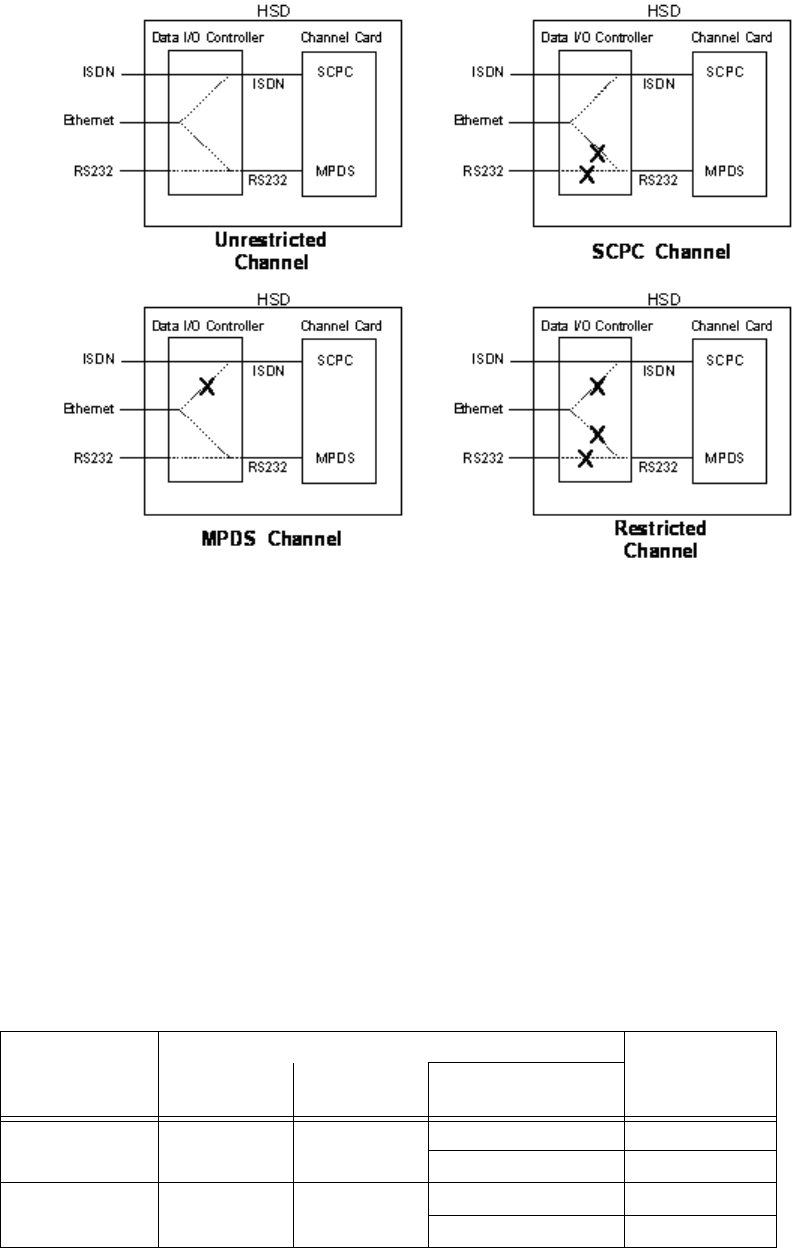
Page 3–22
18 September 2007
SYSTEM DESCRIPTION, INSTALLATION, AND MAINTENANCE MANUAL
eNfusion™ HSD-128 High-speed Data Terminal
Figure 3–7. User Data I/O Mode Configurations – Stand-Alone
(h) ARINC 429 IRS Bus Interface – Stand-Alone
In Stand-Alone Mode installations, navigational information (refer to "System
Description" on page 1-1 for more information) is provided to the HSD through
the high-speed ARINC 429 IRS bus interface. The IRS bus connects through the
top plug of the ARINC 600 connector to the HSD as follows:
• IRS A to TP4J
• IRS B to TP4K
(i) Antenna Interface – Stand-Alone
The ARINC 741 antenna subsystem BSU is interconnected to the HSD as
specified in Table 3–9.
Table 3–9. Stand-Alone Mode HSD to BSU Interconnects
Signal Name
Signal Source Signal
Destination
HSD
Transceiver
Mechanical
HGA
Phased-Array or
Conformal HGA
HPA MUTE A Port BSU-G HSD TP3A
STBD BSU-G HSD TP3C
HPA MUTE B Port BSU-H HSD TP3B
STBD BSU-H HSD TP3D

Page 3–23
18 September 2007
SYSTEM DESCRIPTION, INSTALLATION, AND MAINTENANCE MANUAL
eNfusion™ HSD-128 High-speed Data Terminal
(j) Stand-Alone Mode Connection Details
The tables in this section provide all top, middle, and bottom plug connection
details for Stand-Alone Mode installations.
BSU BITE A BSU-W(G)1 Port BSU-W HSD TP2A
STBD BSU-W HSD TP2C
BSU BITE B BSU-X(H) Port BSU-X HSD TP2B
STBD BSU-X HSD TP2D
MULTI-CONTR
OL A
TP3E BSU-T(A) &
HSD TP1A
MULTI-CONTR
OL B
TP3F BSU-U(B) &
HSD TP1B
NOTE 1:Letters in (brackets) represent EMS SATCOM AMT-50 BSU pin designations
Top/Port
(T/P): Refers to Mechanical (fin-mount) High Gain Antenna (HGA) Subsystem
Port: Refers to Phased Array (Fuselage-mount) or Port side of Dual (side)
Conformal-mount, HGA subsystem
Starboard
(STBD): Refers to Starboard side of Dual (side) Conformal-mount HGA subsystem
Table 3–10. Stand-Alone Mode ARINC 600 Top Plug Connection Details
I/O From
Top Plug Signal Name To Description
I1A Multi-control A TP3E Multi-control from control
card
I1B Multi-control B TP3F Multi-control from control
card
I
2A BSU Top/Port
BITE A
(See Note 1)
Mech. Steered Antenna
(MA): BSU, Pin G1 or W
or Other Antenna2 (OA):
BSU,
PORT-W & Starboard-P
ARINC Tx-HI BITE from
Top/Port BSU
I
2B BSU Top/Port
BITE B
MA: BSU, Pin H or X, or
OA: BSU, PORT-X &
STBD-R
ARINC Tx-LO BITE from
Top/Port BSU
I
2C BSU Starboard
(STBD) BITE A
MA: Not required
OA: BSU, PORT-P &
STBD-W
ARINC Tx-HI BITE from
STBD BSU
Table 3–9. Stand-Alone Mode HSD to BSU Interconnects
Signal Name
Signal Source Signal
Destination
HSD
Transceiver
Mechanical
HGA
Phased-Array or
Conformal HGA

Page 3–24
18 September 2007
SYSTEM DESCRIPTION, INSTALLATION, AND MAINTENANCE MANUAL
eNfusion™ HSD-128 High-speed Data Terminal
I
2D BSU STBD BITE B MA: Not required
OA: BSU, PORT-R &
STBD-X
ARINC Tx-LO BITE from
STBD BSU
I3A Top/Port HPA
MUTE A
MA: Not required
OA: BSU, PORT-G
HPA Mute-A, Port BSU
I3B Top/Port HPA
MUTE B
MA: Not required
OA: BSU, PORT-H
HPA Mute-B, Port BSU
I3C STBD HPA MUTE
A
MA: Not required
OA: BSU, STBD G
HPA Mute-A, STBD BSU
I3D STBD HPA MUTE
B
MA: Not required
OA: BSU, STBD-H
HPA Mute-B, STBD BSU
O
3E OUT Multi-Control
A
IN Multi Ctrl A (TP1A),
and MA: BSU, Pin A or
T, or OA: BSU,
PORT-T & STBD-T
Multi-Control-HI to HSD
& Antenna Subsystem
O
3F OUT Multi-Control
B
IN Multi Ctrl B (TP1B),
and MA: BSU, Pin B or
U, or OA: BSU,
PORT-U &
STBD-U
Multi-Control-LO to HSD
& Antenna Subsystem
I
2K Remote Reset Normally open
momentary switch—
open side. (Closed
side to MP1F)
Remote System Reset
I3G WOW 1 TP3G Weight On Wheel, as
defined in Note 40 of
ARINC 741, Part 1. Refer
to "WOW Pin Wiring –
Stand-Alone" on page
3-13
I3H WOW 2 TP3H
I
3J WOW Program
Select
TP3J
I
4A, 4B,
4C, 4D
System Config 1 to
4
4A & 4C=0 (TP7K
common), 4B &
4D=1(Open)
Stand-Alone Mode
I4E to 4H System Config 5 to
8
Open (1) System Configuration -
not assigned
I4J IRS-A Aircraft main IRS IRS 429 Data, Rx HI
I4K IRS-B Aircraft main IRS IRS 429 Data, Rx LO
I5A SDI 1 Not connected HPA Select Code for
I5B SDI 2 SDI common (TP5D) HPA Select Code for
I5D SDI Common SDI 2 (TP5B) SDI Common for HPA
select codes
Table 3–10. Stand-Alone Mode ARINC 600 Top Plug Connection Details
I/O From
Top Plug Signal Name To Description

Page 3–25
18 September 2007
SYSTEM DESCRIPTION, INSTALLATION, AND MAINTENANCE MANUAL
eNfusion™ HSD-128 High-speed Data Terminal
I5F FWD Address, BIT
24 (LSB)
1=no connection, Six digit Hex ID assigned
by Inmarsat /EMS
I5G FWD Address, BIT
I5H FWD Address, BIT
I5J FWD Address, BIT
I5K FWD Address, BIT
20
I6A FWD Address, BIT
I6B FWD Address, BIT
I6C FWD Address, BIT
I6D FWD Address, BIT
I6E FWD Address, BIT
I6F FWD Address, BIT
I6G FWD Address, BIT
I6H FWD Address, BIT
I6J FWD Address, BIT
I6K FWD Address, BIT
I7A FWD Address, BIT
I7B FWD Address, BIT
I7C FWD Address, BIT
I7D FWD Address, BIT
I7E FWD Address, BIT
I7F FWD Address, BIT
I7G FWD Address, BIT
I7H FWD Address, BIT
I7J FWD Address, BIT
1 (MSB)
I
7K FWD Address,
Common
Common GND
connection for system
and I/O configuration and
Table 3–10. Stand-Alone Mode ARINC 600 Top Plug Connection Details
I/O From
Top Plug Signal Name To Description

Page 3–26
18 September 2007
SYSTEM DESCRIPTION, INSTALLATION, AND MAINTENANCE MANUAL
eNfusion™ HSD-128 High-speed Data Terminal
1. BSU Pin nomenclature for Mechanically-Steered Antennae (MA) is manufacturer dependent.
2. “Other antenna types” (OA) represent either conformal or phased array antennae.
Table 3–11. Stand-Alone Mode ARINC 600 Middle Plug Connection Details
I/O
From
Middle
Plug
Signal Name To Description
O1A LED 1 Remote Status Panel—
Green
HSD—Power On
(Optional)
O1B LED 2 Remote Status Panel—
Red
HSD—Fault (Optional)
O1F LED Common Remote Status LED
Panel, and closed side of
N.O. Remote Reset
Switch
LED Common
O1G Maint Port Tx
(OUT)
Maint Port serial data,
DB9S-2
Maintenance computer
(laptop/PC), for “Remote”
access
I1H Maint Port Rx (IN) Maint Port serial data,
DB9S-3
I/
O
1J Maint Port Signal
Ground.
Maint Port serial data,
DB9S-5
O2A CC (channel
card) #1 Rx
DTE-1A, DB9S-2 or
DB25P-3
User Mobile Packet Data
(MPDS), RS-232, DTE-1A
I2B CC #1 Tx DTE-1A, DB9S-3 or
DB25P-2
I2C CC #1 RTS DTE-1A, DB9S-7 or
DB25P-4
O2D CC #1 CTS DTE-1A, DB9S-8 or
DB25P-5
I2E CC #1 DTR DTE-1A, DB9S-4 or
DB25P-20
O2F CC #1 DSR DTE-1A, DB9S-6 or
DB25P-6
O2G CC #1 CD DTE-1A, DB9S-1 or
DB25P-8
O2H CC #1 RI DTE-1A, DB9S-9 or
DB25P-22
I/
O
2J CC #1 SGND DTE-1A, DB9S-5 or
DB25P-7

Page 3–27
18 September 2007
SYSTEM DESCRIPTION, INSTALLATION, AND MAINTENANCE MANUAL
eNfusion™ HSD-128 High-speed Data Terminal
O3A CC (channel
card)#2 Rx
DTE-1B, DB9S-2 or
DB25P-3
User Mobile Packet Data
(MPDS), RS-232, DTE-1B
I3B CC #2 Tx DTE-1B, DB9S-3 or
DB25P-2
I3C CC #2 RTS DTE-1B, DB9S-7 or
DB25P-4
O3D CC #2 CTS DTE-1B, DB9S-8 or
DB25P-5
I3E CC #2 DTR DTE-1B, DB9S-4 or
DB25P-20
O3F CC #2 DSR DTE-1B, DB9S-6 or
DB25P-6
O3G CC #2 CD DTE-1B, DB9S-1 or
DB25P-8
O3H CC #2 RI DTE-1B, DB9S-9 or
DB25P-22
I/
O
3J CC #2 SGND DTE-1B, DB9S-5 or
DB25P-7
I4G BRI Rx+ISDN, RJ45-3 User Data, ISDN–2
Refer to "User Interfaces –
Stand-Alone" on page 3-17
I4H BRI Rx-ISDN, RJ45-6
O4J BRI Tx+ISDN, RJ45-4
O4K BRI Tx-ISDN, RJ45-5
I5G to 5K I/O CONFIG Pins
1 to 4
See Table 3–8 System Data I/O Mode
Configurations
I6G to 6K I/O CONFIG 5 to
8
Open (1) System Data I/O
Configurations – not
assigned
I6A BRI Rx+ISDN, RJ45-3 User Data, ISDN–1
Refer to "User Interfaces –
Stand-Alone" on page 3-17
I6B BRI Rx -ISDN, RJ45-6
O6C BRI Tx+ISDN, RJ45-4
O6D BRI Tx-ISDN, RJ45-5
Table 3–11. Stand-Alone Mode ARINC 600 Middle Plug Connection Details
I/O
From
Middle
Plug
Signal Name To Description

Page 3–28
18 September 2007
SYSTEM DESCRIPTION, INSTALLATION, AND MAINTENANCE MANUAL
eNfusion™ HSD-128 High-speed Data Terminal
B. Section II: Combined (HCM)/Selective Mode Installation
(1) Combined Mode (HCM)/Selective Mode Installations Wiring Notes
This section provides detailed information on the external interface and system
connections involved in the installation of an HSD transceiver for Combined and
Selective Mode operation.
Note: Selective Mode is a non-standard installation and it is not a recommended
mode of operation. Selective Mode has been superseded by Combined Mode
operation for MCS series SATCOM and with Cooperative Mode operation for
SAT-906 series SATCOM. It is recommended that all systems operating in
Selective Mode be upgraded to support Combined or Cooperative Mode as
applicable.
I7A 10BASE-T Rx+Ethernet 10BASE-T,
RJ45-3
User Data, Ethernet
10BASE-T
(Available in models
1110-A-0150,
1110-A-0160, and in units
with Service Bulletin,
1110-SB-0004
accomplished)
I7B 10BASE-T Rx-Ethernet 10BASE-T,
RJ45-6
O7C 10BASE-T Tx+Ethernet 10BASE-T,
RJ45-1
O7D 10BASE-T Tx-Ethernet 10BASE-T,
RJ45-2
OC1 RF Tx Output Antenna
Subsystem-DLNA
Coax Cable, RF Transmit
Table 3–12. Stand-Alone ARINC 600 Bottom Plug Connection Details
I/O
From
Bottom
Plug
Signal Name To Description
IBP2 +28 V dc HOT Aircraft Power Source,
HOT
+28 V dc supply
IBP3 +28 V dc return
GND
Aircraft Power Source,
return
IBP8 Chassis GND Aircraft Ground Aircraft Chassis Ground
IBP1 115 V ac HOT Aircraft Power Source,
HOT
115 V ac 400 Hz supply
IBP7 115 V ac COLD Aircraft Power Source,
COLD
IBP12 RF Rx Input Antenna
Subsystem-DLNA
Coax Cable, RF
Receive
Table 3–11. Stand-Alone Mode ARINC 600 Middle Plug Connection Details
I/O
From
Middle
Plug
Signal Name To Description

Page 3–29
18 September 2007
SYSTEM DESCRIPTION, INSTALLATION, AND MAINTENANCE MANUAL
eNfusion™ HSD-128 High-speed Data Terminal
Note: All connections, except power and RF, are HSD specific. Refer to “other
SATCOM” and antenna manufacturers’ installation documentation for
interconnection wiring details.
(a) Maintenance Port Interface – Combined/Selective
The HSD transceiver has an RS-232 Maintenance Port interface that provides
access to a maintenance utility program for data loading, system monitoring, and
testing purposes.
Access to the HSD Maintenance Utility Program is achieved by connecting an
RS-232, VT-100 terminal (PC or Laptop operating a terminal emulation program)
to the RS-232 Maintenance Port.
The HSD Maintenance port is available at the front of the HSD and at the rear
ARINC 600 connector. Connection on the front of the HSD is accessible via a
DB25S connector for local maintenance of the unit. Remote access is provided
for cases where local access is unavailable. For remote access, install an
accessible DB9S connector in the cabin area.
Note: The front panel and remote connections to the maintenance port cannot
be used simultaneously.
Refer to "Test and Fault Isolation" on page 4-1 for information on how to connect
and use the maintenance port—including equipment requirements, connection
and cabling requirements, software loading instructions, and configuration
details.
(b) Antenna Subsystem RF Interface – Combined/Selective
Several external RF parameters (such as cable losses and antenna gain), that
must be delimited to ensure proper operation, dictate the HSD performance
requirements. Table 3–13 defines these parameters and their expected values.
(c) WOW Pin Wiring – Combined/Selective
This section describes the requirements for WOW pin wiring.
• Combined Mode Installations
In Combined Mode installations, WOW1, WOW2, and WOW Program Select
are reserved for future use.
Table 3–13. RF Parameters Definition – Combined/Selective
Parameter Min. Value (dB) Max. Value (dB)
Antenna Gain 8 17
Antenna—DLNA Loss 0.1 0.3
DLNA Gain 53 60
DLNA Noise Figure 1.5 1.8
DLNA—HSD (Rx) Loss 6 25
HSD—Antenna (Tx) Loss 1 2.5
DLNA Insertion Loss (Tx to Antenna Port) – 0.8

Page 3–30
18 September 2007
SYSTEM DESCRIPTION, INSTALLATION, AND MAINTENANCE MANUAL
eNfusion™ HSD-128 High-speed Data Terminal
• Selective Mode Installations
Labeled as WOW1, WOW2, and WOW Program Select, these discretes are
wired only if equivalent information is not strapped as being available to the
SDU on an ARINC 429 input [for example, IRS or the Centralized Fault
Display System (CFDS)].
WOW wiring is optional for system operation in Selective Mode installations
as the HSD already receives speed information for Doppler correction.
However, if WOW wiring is not wired, normal maintenance must be disabled
when speed or Doppler readings are greater than zero.
(d) Forward and Return Address IDs – Combined/Selective
Figure 3–8 provides an example of a Forward ID address. The Forward ID is a
Hex number (example: $ABC123) that must be converted into a binary number
for strapping.
Table 3–14. WOW Pin Wiring Table – Combined/Selective
Pin Name and Location
WOW1 WOW2 PGM Aircraft Status
TP3G TP3H TP3J
AFG AFG FAC In-air
OPN AFG FAC Not valid – Default in-air
AFG OPN FAC Not valid – Default in-air
OPN OPN FAC On-ground
AFG AFG OPN On-ground
OPN AFG OPN Not valid – Default in-air
AFG OPN OPN Not valid – Default in-air
OPN OPN OPN In-air
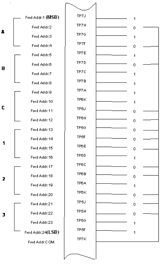
Page 3–31
18 September 2007
SYSTEM DESCRIPTION, INSTALLATION, AND MAINTENANCE MANUAL
eNfusion™ HSD-128 High-speed Data Terminal
Figure 3–8. Forward ID, Hex to Binary Conversion – Combined/Selective
Note: A pin strapped to the same potential as T7K (Forward address common)
is considered as a logical “0”, whereas an open circuit pin is considered
as a logical “1”.
Note: MSB is the Most Significant Bit and LSB is the Least Significant Bit.
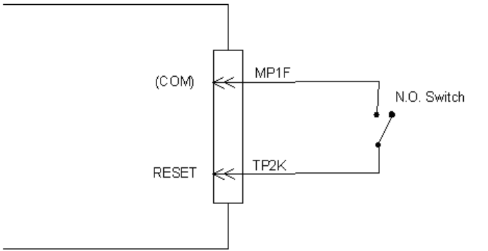
Page 3–32
18 September 2007
SYSTEM DESCRIPTION, INSTALLATION, AND MAINTENANCE MANUAL
eNfusion™ HSD-128 High-speed Data Terminal
(e) Remote Status Panel – Combined/Selective (Optional)
An optional “remote status panel” may be installed in installations where the HSD
units are located in inaccessible or remote locations. The installation of a “remote
status panel” is recommended as it provides visual indications of each of the
power, fault, and call status of each of the units.
A “remote reset switch” for HSD transceivers can also be installed and located
with the Remote Status Panel. Figure 3–10 illustrates a typical wiring diagram
for the remote reset circuit.
1. HSD Remote Reset Switch Circuit Requirements
Note: Combined Mode installations DO NOT support the use of the reset
function. In Selective Mode installations, the use of the reset function
is optional.
HSD transceivers support the installation of a Remote Reset Switch circuit
as shown in Figure 3–9.
The HSD Remote Reset circuit requires less than 100 ohms between TP1K
(RESET) and MP1F(COM) to be asserted and greater than 10 kilohms to be
de-asserted (include all cable and switch contact resistance).
2. HSD Remote LED Driver Circuit Requirements
The circuit requirements for the HSD Remote Status LED drivers are shown
in Figure 3–10. Each LED driver circuit has a 200-ohm current limit resistor.
The maximum cable resistance (including the forward and return paths) must
not exceed 100 ohms to provide adequate current to the 5 volt LEDs (i.e. 10
mA minimum) at the remote status panel.
It is recommended that the installer use shielded cables to provide a level of
noise immunity.
Figure 3–9. HSD Remote Reset Circuit – Combined/Selective
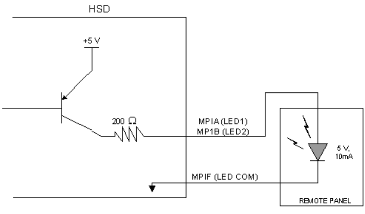
Page 3–33
18 September 2007
SYSTEM DESCRIPTION, INSTALLATION, AND MAINTENANCE MANUAL
eNfusion™ HSD-128 High-speed Data Terminal
Figure 3–10. HSD Remote LED Panel Circuit – Combined/Selective
(f) User Interfaces – Combined/Selective
To facilitate user access to the HSD interfaces, install the following connectors
in the appropriate cabin area.
Note: Although the Ethernet interface is only supported by HSD-X transceivers,
HSD transceiver models, PN 1110-A-0150 and 1110-A-0160, and other
models of HSD transceivers with service bulletin 1110-SB-0004
accomplished, consider pre-wiring the cabin for all interfaces—even when
installing an HSD transceiver that currently does not support the Ethernet
interface.
1. ISDN Interface
Install an RJ-45 interface connector in the cabin area for user connections to
the ISDN interface. RJ-45 Connector Termination Details below describes the
RJ-45 connector and cable termination.
2. RS-232 Interface (MPDS)
Install a DB9S interface connector in the cabin area for connection to the
RS-232 interface. Refer to the HSD Interconnection Drawings for pinout
designation.
3. Ethernet Data Interface
HSD transceiver models, part numbers 1110-A-0150 and 1110-A-0160
support the Ethernet interface. All other models of HSD transceivers must
have service bulletin 1110-SB-0004 accomplished to support the Ethernet
interface.

Page 3–34
18 September 2007
SYSTEM DESCRIPTION, INSTALLATION, AND MAINTENANCE MANUAL
eNfusion™ HSD-128 High-speed Data Terminal
Install an RJ-45 interface connector in the cabin area for user access to the
Ethernet interface. The next paragraph, describes the RJ-45 connector and
cable termination.
4. RJ-45 Connector Termination Details
Details relating to the RJ45 cable terminations, required for both the ISDN
and/or 10BASE-T services, are shown in Table 3–15 and Figure 3–11.
Use LAN cables that meet flammability and TIA/EIA568-A CAT-5
requirements. Cables #922404(4 conductor) and # 922408 (8 conductor), as
supplied by Electronics Cable Specialists, are acceptable. Equivalent
substitutions from other manufacturers may be used.
Figure 3–11. RJ-45 Connector Terminator Details – Combined/Selective
Table 3–15. RJ45 Wiring Details – Combined/Selective
Signal
SERVICE
EURO ISDN Ethernet 10BASE-T
Pin
Cable
Pin
Cable
ECS Other ECS Other
RX + 3 White White/Green 3 White White/Orange stripe
RX−6 Blue Green 6 Green Orange/White stripe or
solid Orange
TX+ 4 White Blue 1 White White/Green stripe
TX−5 Orange White/Blue 2 Brown Green/White stripe or
solid Green

Page 3–35
18 September 2007
SYSTEM DESCRIPTION, INSTALLATION, AND MAINTENANCE MANUAL
eNfusion™ HSD-128 High-speed Data Terminal
5. System Configuration Pin Strapping – Combined/Selective
The HSD adjusts its configuration according to the status of several strap pins
on the rear ARINC 600 connector.
Configuration pins are assigned based on system-mode-configuration
selection and data input/output (I/O) requirements as shown in Table 3–16.
Detailed pin assignment is shown in Table 3–17 and Table 3–18.
Note: The logic for the System Configuration pins is reverse to the logic
explained in ARINC 741 Characteristic Attachment 1-4, Note 19. For
System Configuration pins, 0=strapped to common and 1=open.
• Pins marked “0” are signaled by strapping to “Fwd Address
Common” (T7K).
• Pins marked “1” are signaled by an open circuit—no connection.
• Configurations resulting in all “1’s” are invalid.
6. System Mode Strap Pins Coding – Combined/Selective
The HSD must be externally strapped according to its intended operational
configuration mode. Table 3–17 illustrates the system pin strapping for all
HSD operational modes and configurations. The HCM Mode is highlighted
as an example.
Table 3–16. Configuration Pin Summary – Combined/Selective
Pin # Name Function
TP4A to D System Config #1 to #4 System Mode (See Table 3–17)
TP4E to H System Config #5 to #8 Not assigned (set to"1")
MP5G to K Data I/O Config #1 to #4 NOTE: Data I/O Mode (See Table 3–18)
MP6G to K Data I/O Config #5 to #8 Not assigned (set to"1")
Table 3–17. Combined Mode System Mode Pin Strapping
Pin Status
System Modes TP4A TP4B TP4C TP4D
1234
INVALID 1111
Stand-Alone 0101
Selective, SAT-9061101
Selective, MCS-30001011
Selective, MCS-60001001
Selective, MCS-70000111
Honeywell Combined1110
Reserved 1100

Page 3–36
18 September 2007
SYSTEM DESCRIPTION, INSTALLATION, AND MAINTENANCE MANUAL
eNfusion™ HSD-128 High-speed Data Terminal
Note: The logic for the System Mode pins is reverse to the logic explained in ARINC
741 Characteristic Attachment 1-4, Note 19. For System Mode pins,
0=strapped to common and 1=open.
• Pins marked “0” are signaled by strapping to “Fwd Address
Common” (TP7K).
• Pins marked “1” are signaled by an open circuit—no connection.
• Configuration resulting in all “1’s” is Invalid.
7. User Data I/O Mode Pin Strapping – Combined/Selective
Data I/O Mode Pin strapping is only required for HSD transceivers models,
PN 1110-A-0150 and 1110-A-0160 or other HSD models that have Data I/O
Type 2 cards installed via Service Bulletin 1110-SB-0004.
The following settings allow placing restrictions on the way both channels are
used. If the user has no specific requirements then it is recommended to leave
both channels as “Unrestricted.”
In HSD transceivers with two channel cards, both channels are accessible
for Swift64 Mobile ISDN via the ISDN port on a first come-first served basis.
All four modes, as detailed in Table 3–18, are also described in Figure 3–12.
In units where all Data I/O services are available (including Ethernet), the
following statements are valid:
• The channel cards are pooled, which means that no particular card is
operated in one of the selected modes.
• If one channel card becomes inoperative, and there is a conflicting
configuration (for example, 1 Reserved, 1 SCPC – for Swift64 Mobile
ISDN), then the remaining card operates in "Unrestricted" mode.
• A “restricted” channel is not handled by the Data I/O Controller, which
results in the channel not being accessible for SCPC via Ethernet or for
MPDS via RS232 or Ethernet.
• An SCPC channel is accessible for SCPC via Ethernet.
• An MPDS channel is accessible for MPDS via RS232 and Ethernet.
• An “unrestricted” channel is accessible for SCPC via Ethernet and MPDS
via RS232 and Ethernet.
Note: Use a ”Restricted” Data I/O Mode if only ISDN service is available.
Collins Cooperative 0011
Multi-Channel 0001
Table 3–17. Combined Mode System Mode Pin Strapping
Pin Status
System Modes TP4A TP4B TP4C TP4D
1234

Page 3–37
18 September 2007
SYSTEM DESCRIPTION, INSTALLATION, AND MAINTENANCE MANUAL
eNfusion™ HSD-128 High-speed Data Terminal
Note: (‘0’ = FWD Address Common, ‘1’ No Connection)
Table 3–18. Data I/O Mode Pin Strapping – Combined/Selective
Pin Status Data I/O Mode
MP5G MP5H MP5J MP5K
1111Invalid
11101 Restricted, 1 Unrestricted
11011 Restricted, 1 SCPC
11001 Restricted, 1 MPDS
10112 Restricted (ISDN only)
10102 SCPC
10011 SCPC, 1 Unrestricted
10002 MPDS
01111 MPDS, 1 Unrestricted
01101 SCPC, 1 MPDS
01012 Unrestricted (recommended if no
specific user requirements)
0000Reserved
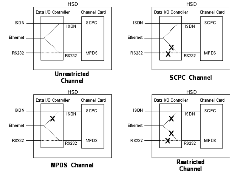
Page 3–38
18 September 2007
SYSTEM DESCRIPTION, INSTALLATION, AND MAINTENANCE MANUAL
eNfusion™ HSD-128 High-speed Data Terminal
Figure 3–12. User Data I/O Mode Configurations – Combined/Selective
(g) ARINC 429 IRS Bus Interface – Combined/Selective
In HCM Combined Mode and Selective Mode installations, navigational
information (refer to "System Description" on page 1-1 for details) is provided to
the HSD through the high-speed ARINC 429 IRS bus interface. The IRS bus
connects through the top plug of the ARINC 600 connector to the HSD as follows:
• IRS A to TP4J
• IRS B to TP4K
(h) Antenna Interface – Combined/Selective
The SATCOM Aero H/H+ system provides the interface to the antenna. Refer to
Honeywell documentation for specific details.
(i) RF Splitter Installation – Combined/Selective
Refer to the Interconnection Diagrams for cabling details. Refer to Table 3–19
for a list of the required cable assembly parts. Substitutions using different parts
of equivalent functionality are acceptable.
Note: Before installing the RF splitter, read all of the steps included in the
following splitter installation procedure.
Note: Actual splitter mounting location may vary depending on the placement of
the existing RFU and HPA assemblies.

Page 3–39
18 September 2007
SYSTEM DESCRIPTION, INSTALLATION, AND MAINTENANCE MANUAL
eNfusion™ HSD-128 High-speed Data Terminal
To install the RF Splitter:
1. Determine a suitable location near the RFU to secure the splitter.
2. Cut the receive coax cable at the splitter mounting location.
3. Re-terminate the cut ends with TNC coax connectors
4. Connect the end coming from the antenna subsystem to the splitter input (S)
connector.
5. Connect the end going to TPC1 of the RFU to one of the output ports of the
splitter, one or two.
6. Run a new coax cable (length is installation specific) from the unused splitter
output port to BP-12 of the ARINC 600 connector of the HSD tray assembly.
(j) Combined/Selective Mode Connection Details
The tables in this section provide all top, middle, and bottom plug connection
details for Combined and Selective Mode installations.
Table 3–19. Receive Path Parts Requirements – Combined/Selective
Item Manufacturer
PN
EMS SATCOM
PN Description
RF Splitter ZAPD-2-TNC 32800004 Mini-Circuit, 2-way 0°, TNC, Splitter
Receive Coax 432101 – ECS, Coax Cable, 0.130 O.D.,
50Ω, 17.5 dB/100 ft @ 1.5 GHz
Connector
(@ Splitter)
CTS522 – ECS, TNC, Straight Plug
Connector
(@ BP12)
P522 – ECS, ARINC 600, Size 5, Socket
Table 3–20. Combined/Selective Mode ARINC 600 Top Plug Connection Details
I/O From
Top Plug Signal Name To Description
I/O
1A to 1D Multi-Control IN and
BITE OUT
As per avionics
manufacturer’s
documentation
Multi-Control and BITE
I2A BSU Top/Port BITE A SDU, MP7G ARINC Tx-HI BITE
From Top/Port BSU
I2B BSU Top/Port BITE B SDU, MP7H ARINC Tx-LO BITE
From Top/Port BSU
I
2C BSU STBD BITE A Mechanically
Steered Antenna1
(MA): Not required
Other Antenna2
(OA): SDU, MP7J
ARINC Tx-HI BITE
From STBD BSU

Page 3–40
18 September 2007
SYSTEM DESCRIPTION, INSTALLATION, AND MAINTENANCE MANUAL
eNfusion™ HSD-128 High-speed Data Terminal
I2D BSU STBD BITE B MA: Not required
OA: SDU, MP7K
ARINC Tx-LO BITE
From STBD BSU
I
3A to 3D HPA MUTE MA: Not required
As per avionics
manufacturer’s
documentation
HPA Mute-A & B to BSU
I
2K Remote Reset Normally Open
momentary
switch—open side
(Closed side to
MP1F)
Remote System Reset
(Optional; not
recommended for
Combined Mode)
I3G WOW 1 TP3G Weight On Wheel, as
defined in Note 40 of
ARINC 741
I3H WOW2 TP3H
I3J WOW Program Select TP3J
I4A to 4D System Config 1 to 4 System Mode
Configurations
I
4E to 4H System Config 5 to 8 Open (1) System Mode
configuration-not
assigned
I4J IRS-A Aircraft main IRS IRS 429 Data, Rx HI
I4K IRS-B Aircraft main IRS IRS 429 Data, Rx LO
I
5A, 5B, &
5D
SDI 1, SDI 2, & SDI
Common
As per avionics
manufacturer’s
documentation
HPA Select Code for
HGA
I
5F FWD Address, BIT 24
(LSB)
1=no connection,
0=Common (TP7K)
Six digit Hex ID assigned
by Inmarsat /EMS
SATCOM
Table 3–20. Combined/Selective Mode ARINC 600 Top Plug Connection Details
I/O From
Top Plug Signal Name To Description

Page 3–41
18 September 2007
SYSTEM DESCRIPTION, INSTALLATION, AND MAINTENANCE MANUAL
eNfusion™ HSD-128 High-speed Data Terminal
I5G FWD Address, BIT 23
I5H FWD Address, BIT 22
I5J FWD Address, BIT 21
I5K FWD Address, BIT 20
I6A FWD Address, BIT 19
I6B FWD Address, BIT 18
I6C FWD Address, BIT 17
I6D FWD Address, BIT 16
I6E FWD Address, BIT 15
I6F FWD Address, BIT 14
I6G FWD Address, BIT 13
I6H FWD Address, BIT 12
I6J FWD Address, BIT 11
I6K FWD Address, BIT 10
I7A FWD Address, BIT 9
I7B FWD Address, BIT 8
I7C FWD Address, BIT 7
I7D FWD Address, BIT 6
I7E FWD Address, BIT 5
I7F FWD Address, BIT 4
I7G FWD Address, BIT 3
I7H FWD Address, BIT 2
I7J FWD Address, BIT 1
(MSB)
I
7K FWD Address,
Common
Common GND
connection for system
and I/O configuration and
FWD ID
1. BSU Pin nomenclature for Mechanically-Steered Antennae (MA) is manufacturer dependent.
Table 3–20. Combined/Selective Mode ARINC 600 Top Plug Connection Details
I/O From
Top Plug Signal Name To Description

Page 3–42
18 September 2007
SYSTEM DESCRIPTION, INSTALLATION, AND MAINTENANCE MANUAL
eNfusion™ HSD-128 High-speed Data Terminal
2. “Other antenna types” (OA) represent either conformal or phased array antennae.
Table 3–21. Combined/Selective Mode ARINC 600 Middle Plug Connection Details
I/O
From
Middle
Plug
Signal Name To Description
O1A LED 1 Remote Status
Panel—Green
HSD-64—Power On
(Optional)
O1B LED 2 Remote Status
Panel—Red
HSD-64—Fault (Optional)
O
1F LED Common Remote Status LED
Panel and closed side
of N.O. Remote Reset
switch (if used)
LED Common
O1G Maint Port Tx (Out) Maint Port serial data,
DB9S-2
Maintenance Laptop/PC,
for “Remote” access
I1H Maint Port Rx (In) Maint Port serial data,
DB9S-3
1J Maint Port Signal
GND
Maint Port serial data,
DB9S-5
O2A Channel Card (CC)
#1 Rx
DTE-1A, DB9S-2 User Mobile Packet Data
(MPDS),
RS-232, DTE-1A
I2B CC #1 Tx DTE-1A, DB9S-3
I2C CC #1 RTS DTE-1A, DB9S-7
O2D CC #1 CTS DTE-1A, DB9S-8
I2E CC #1 DTR DTE-1A, DB9S-4
O2F CC #1 DSR DTE-1A, DB9S-6
O2G CC #1 DCD DTE-1A, DB9S-1
O2H CC #1 RI DTE-1A, DB9S-9
I/O 2J CC #1 SGND DTE-1A, DB9S-5
I
6A BRI RX+ RJ45-3 User Data, ISDN–1
Refer to "User Interfaces –
Combined/Selective" on
page 3-33
I6B BRI RX- RJ45-6
O6C BRI TX+ RJ45-4
O6D BRI TX- RJ45-5

Page 3–43
18 September 2007
SYSTEM DESCRIPTION, INSTALLATION, AND MAINTENANCE MANUAL
eNfusion™ HSD-128 High-speed Data Terminal
I5G to 5K I/O CONFIG Pins 1 to
4
See Table 3–8 System Data I/O Mode
Configurations
I6G to 6K I/O CONFIG Pins 5 to
8
Open (1) Data I/O Config – not
assigned
I4G BRI Rx+ ISDN, RJ45-3 User Data, ISDN–2
(Provisional)
I4H BRI Rx-ISDN RJ45-6
O4J BRI Tx+ ISDN, RJ45-4
O4K BRI Tx-ISDN, RJ45-5
I7A 10BASE-T Rx+ Ethernet 10BASE-T,
RJ45-3
User Data,
Ethernet 10BASE-T
(Available in models
1110-A-0150,
1110-A-0160, and in units
with Service Bulletin,
1110-SB-0004
accomplished)
I7B 10BASE-T Rx-Ethernet 10BASE-T,
RJ45-6
O7C 10BASE-T Tx+Ethernet 10BASE-T,
RJ45-1
O7D 10BASE-T Tx-Ethernet 10BASE-T,
RJ45-2
OC1 RF Tx Output Antenna
Subsystem-DLNA
Coax Cable, RF Transmit
Table 3–22. Combined/Selective Mode ARINC 600 Bottom Plug Connection
Details
I/O
From
Bottom
Plug
Signal Name To Description
I2 +28 V dc HOT Aircraft Power
Source, HOT
+28 V dc supply
I3 +28 V dc Rtn GND Aircraft Power
Source, Rtn
I8 Chassis GND Aircraft Ground Aircraft Chassis Ground
I1 115 V ac HOT Aircraft Power
Source, HOT
115 V ac 400 Hz supply
I7 115 V ac COLD Aircraft Power
Source, COLD
I12 RF Rx Input RF Rx Splitter output
port
RF Receive from Antenna
Subsystem
Table 3–21. Combined/Selective Mode ARINC 600 Middle Plug Connection Details
I/O
From
Middle
Plug
Signal Name To Description
Page 3–44
18 September 2007
SYSTEM DESCRIPTION, INSTALLATION, AND MAINTENANCE MANUAL
eNfusion™ HSD-128 High-speed Data Terminal
C. Section III: Cooperative Mode Installation
(1) Cooperative Mode Installations Wiring Notes
This section provides detailed information on the external interface and system
connections involved in the installation of an HSD transceiver in Cooperative Mode
operation.
(a) General Overview – Cooperative Mode
This section describes external interfaces unique to HSD Transceivers operating
in Collins SAT-906 Cooperative-Mode. For detailed interface descriptions, refer
to the Cooperative Mode, Interconnection Diagram, (1110-B-0156).
Note: All connections, except power and RF, are HSD specific. Refer to “other
SATCOM” and antenna manufacturers’ installation documentation for
interconnection wiring details.
To achieve the current “best system” operation performance, the HSD should
have EMS SATCOM service bulletin 1110-SB-0015 incorporated (service bulletin
1110-SB-0015 supercedes 1110-SB-0003). Cooperative Mode installations that
use an HSD without a minimum of service bulletin 1110-SB-0003 (control
processor software version 4.5) incorporated will occasionally generate Disable
0100, Disable 0800, and Disable 1000 SAT-906 system errors.
Cooperative Mode system installations that use an HSD with service bulletin
1110-SB-0003 incorporated operate with improved system performance and
should only generate Disable 1000 SAT-906 system errors (Disable 1000 errors
occur on approximately 1% of M4 call terminations). This error occurs due to the
HSD reporting a lower than expected actual power out value in the HPA Status
Word on the ARINC 429 HPA BITE bus.
Currently, Cooperative Mode installations only support single channel card
configurations. If installing a dual-channel HSD transceiver in a Cooperative
Mode environment, use the maintenance port utility to configure the EEPROM
setting, in Menu 3, for a single channel card.
The following general wiring notes must be considered before installing an HSD
transceiver for Cooperative Mode operation with the Collins SAT-906 system.
• Splitter for the RX path
• System Configuration strapping is set to “Cooperative Rockwell-Collins
SAT-906” in the EEPROM parameter for software versions 4.5. External
system strapping to “Collins Cooperative” Mode is used for installations
operating software versions 5.7 or later (1110-SB-0011). Software versions
5.7 or later “read” the hardware strapping to automatically identify the system
configuration.
Add the following HSD-specific wiring:
• Forward ID Address (Category B)
• Antenna to BSU BITE information from SDU
• A “Tx Disable” line from the SDU to the HSD
• ARINC 429 SDU to/from HSD, Crosstalk BUS lines
Other HSD-specific wiring includes:

Page 3–45
18 September 2007
SYSTEM DESCRIPTION, INSTALLATION, AND MAINTENANCE MANUAL
eNfusion™ HSD-128 High-speed Data Terminal
• ISDN, Ethernet (if supported with an installed Data I/O Type 2 Card), and/or
MPDS (RS-232) interface wiring
• System and Data I/O Configuration lines
• Optional maintenance and LED remote interfaces
(b) Rockwell Collins Requirements for Cooperative Operation with SAT-906
At the time of printing, the SAT-906 SDU needs, at a minimum, core software –
068, that includes service bulletins 31 and 501, which changes the unit to a –
150 designation with wiring SDU pin TP12E grounded to indicate that the SDU
is operating with an HSD.
The Collins Owner Requirements Table (ORT) must updated with the latest
version, ORT generation tool.
(c) Maintenance Port Interface – Cooperative Mode
The HSD transceiver has an RS-232 Maintenance Port interface that provides
access to a maintenance utility program for data loading, system monitoring and
testing purposes.
Access to the HSD Maintenance Utility Program is achieved by connecting an
RS-232, VT-100 terminal (PC or Laptop operating a terminal emulation program)
to the RS-232 Maintenance Port.
The HSD Maintenance port is available at the front of the HSD and at the rear
ARINC 600 connector. Connection on the front of the HSD is accessible via a
DB25S connector for local maintenance of the unit. Remote access is provided
for cases where local access is unavailable. For remote access, install an
accessible DB9S connector in the cabin area.
Note: The front panel and remote connections to the maintenance port cannot
be used simultaneously.
Refer to "Test and Fault Isolation" on page 4-1 for information on how to connect
and use the maintenance port—including, equipment requirements, connection
and cabling requirements, software loading instructions, and configuration
details.
(d) Antenna Subsystem RF Interface – Cooperative Mode
Several external RF parameters (such as cable losses and antenna gain), that
must be delimited to ensure proper operation, dictate the HSD performance
requirements. Table 3–23 defines these parameters and their expected values.
Table 3–23. RF Parameters Definition – Cooperative Mode
Parameter Min. Value (dB) Max. Value (dB)
Antenna Gain 8 17
Antenna—DLNA Loss 0.1 0.3
DLNA Gain 53 60
DLNA Noise Figure 1.5 1.8
DLNA—HSD (Rx) Loss 6 25

Page 3–46
18 September 2007
SYSTEM DESCRIPTION, INSTALLATION, AND MAINTENANCE MANUAL
eNfusion™ HSD-128 High-speed Data Terminal
(e) WOW Pin Wiring – Cooperative Mode
In Cooperative Mode installations, WOW 2 discrete is re-assigned as Tx- Disable
and is therefore not used.
(f) Forward and Return Address IDs – Cooperative Mode
Figure 3–13 provides an example of a Forward ID address. The Forward ID is a
Hex number (example: $ABC123) that must be converted into a binary number
for strapping.
HSD—Antenna (Tx) Loss 1 2.5
DLNA Insertion Loss (Tx to Antenna Port) – 0.8
Table 3–23. RF Parameters Definition – Cooperative Mode
Parameter Min. Value (dB) Max. Value (dB)
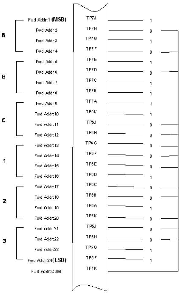
Page 3–47
18 September 2007
SYSTEM DESCRIPTION, INSTALLATION, AND MAINTENANCE MANUAL
eNfusion™ HSD-128 High-speed Data Terminal
Figure 3–13. Forward ID, Hex to Binary Conversion – Cooperative Mode
Note: A pin strapped to the same potential as T7K (Forward address common)
is considered as a logical “0”, whereas an open circuit pin is considered
as a logical “1”.
Note: MSB is the Most Significant Bit and LSB is the Least Significant Bit.
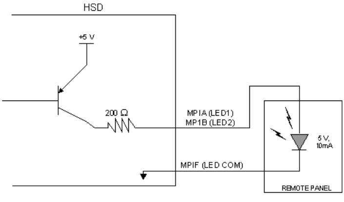
Page 3–48
18 September 2007
SYSTEM DESCRIPTION, INSTALLATION, AND MAINTENANCE MANUAL
eNfusion™ HSD-128 High-speed Data Terminal
(g) Remote Status Panel – Cooperative Mode (Optional)
An optional “remote status panel” may be installed in installations where the HSD
is located in inaccessible or remote locations. The installation of a “remote status
panel” is recommended as it provides visual indications of each of the power,
fault, and call status of the HSD.
Note: Cooperative Mode installations DO NOT support the use of the reset
function.
1. HSD Remote LED Driver Circuit Requirements – Cooperative Mode
The circuit requirements for the HSD Remote Status LED drivers are shown
in Figure 3–14. Each LED driver circuit has a 200-ohm current limit resistor.
The maximum cable resistance (including the forward and return paths) must
not exceed 100 ohms to provide adequate current to the 5 volt LEDs (i.e. 10
mA minimum) at the remote status panel.
It is recommended that the installer use shielded cables to provide a level of
noise immunity.
Figure 3–14. HSD Remote LED Panel Circuit – Cooperative Mode
(h) User Interfaces – Cooperative Mode
To facilitate user access to the HSD interfaces, install the following connectors
in the appropriate cabin area.
Note: Although the Ethernet interface is only supported by HSD-X transceivers,
HSD transceiver models, PN 1110-A-0150 and 1110-A-0160, and other
models of HSD transceivers with service bulletin 1110-SB-0004
accomplished, consider pre-wiring the cabin for all interfaces—even when
installing an HSD transceiver that currently does not support the Ethernet
interface.

Page 3–49
18 September 2007
SYSTEM DESCRIPTION, INSTALLATION, AND MAINTENANCE MANUAL
eNfusion™ HSD-128 High-speed Data Terminal
1. ISDN Interface
Install an RJ-45 interface connector in the cabin area for user connections to
the ISDN interface. "RJ-45 Connector Termination Details" on page 3-49
describes the RJ-45 connector and cable termination.
2. RS-232 Interface (MPDS)
Install a DB9S interface connector in the cabin area for connection to the
RS-232 interface. Refer to the HSD Interconnection Drawing for pinout
designation.
3. Ethernet Data Interface
HSD transceiver models, part numbers 1110-A-0150 and 1110-A-0160
support the Ethernet interface. All other models of HSD transceivers must
have service bulletin 1110-SB-0004 accomplished to support the Ethernet
interface.
Install an RJ-45 interface connector in the cabin area for user access to the
Ethernet interface. "RJ-45 Connector Termination Details" on page 3-49
describes the RJ-45 connector and cable termination.
4. RJ-45 Connector Termination Details
Details relating to the RJ-45 cable terminations, required for both the ISDN
and/or 10BASE-T services, are shown in Table 3–24 and Figure 3–15.
Use LAN cables that meet flammability and TIA/EIA568-A CAT-5
requirements. Cables #922404(4 conductor) and # 922408 (8 conductor), as
supplied by Electronics Cable Specialists, are acceptable. Equivalent
substitutions from other manufacturers may be used.
Table 3–24. RJ-45 Wiring Details – Cooperative Mode
Signal
SERVICE
EURO ISDN Ethernet 10BASE-T
Pin
Cable
Pin
Cable
ECS Other ECS Other
RX + 3 White White/Green 3 White White/Orange stripe
RX−6 Blue Green 6 Green Orange/White stripe or
solid Orange
TX+ 4 White Blue 1 White White/Green stripe
TX−5 Orange White/Blue 2 Brown Green/White stripe or
solid Green
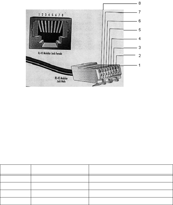
Page 3–50
18 September 2007
SYSTEM DESCRIPTION, INSTALLATION, AND MAINTENANCE MANUAL
eNfusion™ HSD-128 High-speed Data Terminal
Figure 3–15. RJ-45 Connector Terminator Details – Cooperative Mode
5. System Configuration Pin Strapping – Cooperative Mode
The HSD adjusts its configuration according to the status of several strap pins
on the rear ARINC 600 connector.
Configuration pins are assigned based on system-mode-configuration
selection, and data input/output (I/O) requirements as shown in Table 3–25.
Detailed pin assignment is shown in Table 3–26 and Table 3–27.
Note: The logic for the System Configuration pins is reverse to the logic
explained in ARINC 741 Characteristic Attachment 1-4, Note 19. For
System Configuration pins, 0=strapped to common and 1=open.
• Pins marked “0” are signaled by strapping to “Fwd Address
Common” (T7K).
• Pins marked “1” are signaled by an open circuit—no connection.
• Configurations resulting in all “1’s” are invalid.
6. System Mode Strap Pins Coding – Cooperative Mode
The HSD must be externally strapped as highlighted in Table 3–26; it
illustrates the system pin strapping for operation in Cooperative Mode (with
Collins SAT-906).
Table 3–25. Configuration Pin Summary – Cooperative Mode
Pin # Name Function
TP4A to D System Config #1 to #4 System Mode (See Table 3–26)
TP4E to H System Config #5 to #8 Not assigned (set to"1")
MP5G to K Data I/O Config #1 to #4 NOTE: Data I/O Mode (See Table 3–27)
MP6G to K Data I/O Config #5 to #8 Not assigned (set to"1")

Page 3–51
18 September 2007
SYSTEM DESCRIPTION, INSTALLATION, AND MAINTENANCE MANUAL
eNfusion™ HSD-128 High-speed Data Terminal
Note: The logic for the System Mode pins is reverse to the logic explained
in ARINC 741 Characteristic Attachment 1-4, Note 19. For System
Mode pins, 0=strapped to common and 1=open.
• Pins marked “0” are signaled by strapping to “Fwd Address
Common” (TP7K).
• Pins marked “1” are signaled by an open circuit—no connection.
• Configuration resulting in all “1’s” is Invalid.
7. User Data I/O Mode Pin Strapping – Cooperative Mode
Data I/O Mode Pin strapping is only required for HSD transceivers models,
PN 1110-A-0150 and 1110-A-0160 or other HSD models that have Data I/O
Type 2 cards installed via Service Bulletin 1110-SB-0004.
The following settings allow placing restrictions on the way both channels are
used. If the user has no specific requirements then it is recommended to leave
both channels as “Unrestricted.”
In HSD transceivers with two channel cards, both channels are accessible
for Swift64 Mobile ISDN via the ISDN port on a first come-first served basis.
All four modes, as detailed in Table 3–27, are also described in Figure 3–16.
In units where all Data I/O services are available (including Ethernet), the
following statements are valid:
• The channel cards are pooled, which means that no particular card
is operated in one of the selected modes.
• If one channel card becomes inoperative, and there is a conflicting
configuration (for example, 1 Reserved, 1 SCPC – for Swift64
Mobile ISDN), then the remaining card operates in "Unrestricted"
mode.
Table 3–26. System Mode Pin Strapping – Cooperative Mode
System Modes
Pin Status
TP4A TP4B TP4C TP4D
1234
INVALID 1111
Stand Alone 0101
Selective, SAT-906 1101
Selective, MCS-30001011
Selective, MCS-60001001
Selective, MCS-70000111
Honeywell Combined1110
Reserved 1100
Collins Cooperative 0011
Multi-Channel 0001

Page 3–52
18 September 2007
SYSTEM DESCRIPTION, INSTALLATION, AND MAINTENANCE MANUAL
eNfusion™ HSD-128 High-speed Data Terminal
• A “restricted” channel is not handled by the Data I/O Controller,
which results in the channel not being accessible for SCPC via
Ethernet or for MPDS via RS232 or Ethernet.
• An SCPC channel is accessible for SCPC via Ethernet.
• An MPDS channel is accessible for MPDS via RS232 and
Ethernet.
• An “unrestricted” channel is accessible for SCPC via Ethernet and
MPDS via RS232 and Ethernet.
Note: Use a ”Restricted” Data I/O Mode if only ISDN service is available.
Note: (‘0’ = FWD Address Common, ‘1’ No Connection)
Table 3–27. Data I/O Mode Pin Strapping – Cooperative Mode
Pin Status Data I/O Mode
MP5G MP5H MP5J MP5K
1111Invalid
11101 Restricted, 1 Unrestricted
11011 Restricted, 1 SCPC
11001 Restricted, 1 MPDS
10112 Restricted (ISDN only)
10102 SCPC
10011 SCPC, 1 Unrestricted
10002 MPDS
01111 MPDS, 1 Unrestricted
01101 SCPC, 1 MPDS
01012 Unrestricted (recommended if no
specific user requirements)
0000Reserved

Page 3–53
18 September 2007
SYSTEM DESCRIPTION, INSTALLATION, AND MAINTENANCE MANUAL
eNfusion™ HSD-128 High-speed Data Terminal
Figure 3–16. User Data I/O Mode Configurations – Cooperative Mode
(i) ARINC 429 IRS Bus Interface – Cooperative Mode
Although the IRS bus connections are not required, the installation of provisional
wiring for these connections is recommended.
(j) Antenna Interface – Cooperative Mode
The SAT-906 Aero H/H+ system provides the interface to the antenna. Refer to
Rockwell Collins SAT-906 documentation for specific details.
(k) RF Splitter Installation – Cooperative Mode
Refer to Table 3–28 for a list of the required cable assembly parts. Substitutions
using different parts of equivalent functionality are acceptable.
Note: Before installing the RF splitter, read all of the steps included in the
following splitter installation procedure.
Note: Actual splitter mounting location may vary depending on the placement of
the existing RFU and HPA assemblies.
To install the RF Splitter:
1. Determine a suitable location near the RFU to secure the splitter.
2. Cut the receive coax cable at the splitter mounting location.
3. Re-terminate the cut ends with TNC coax connectors.

Page 3–54
18 September 2007
SYSTEM DESCRIPTION, INSTALLATION, AND MAINTENANCE MANUAL
eNfusion™ HSD-128 High-speed Data Terminal
4. Connect the end coming from the antenna subsystem to the splitter input (S)
connector.
5. Connect the end going to TPC1 of the RFU to one of the output ports of the
splitter, one or two.
6. Run a new coax cable (length is installation specific) from the unused splitter
output port to BP-12 of the ARINC 600 connector of the HSD tray assembly.
(l) Cooperative Mode Connection Details
The tables in this section provide all top, middle, and bottom plug connection
details for Cooperative Mode installations.
Table 3–28. Receive Path Parts Requirements – Cooperative Mode
Item Manufacturer PN
EMS
SATCOM
PN
Description
RF Splitter ZAPD-2-TNC 32800004 Mini-Circuit, 2-way 0°, TNC,
Splitter
Receive Coax 432101 – ECS, Coax Cable, 0.130 O.D.,
50Ω, 17.5 dB/100 ft @ 1.5 GHz
Connector (@
Splitter)
CTS522 – ECS, TNC, Straight Plug
Connector (@
BP12)
P522 – ECS, ARINC 600, Size 5, Socket
Table 3–29. Cooperative Mode ARINC 600 Top Plug Connection Details
I/O From
Top Plug Signal Name To Description
I/O 1A to 1D Multi-Control IN and
BITE OUT
As per Collins
documentation
Multi-Control and BITE
I2A BSU Top/Port BITE A SDU, MP7G ARINC Tx-HI BITE
From Top/Port BSU
I2B BSU Top/Port BITE B SDU, MP7H ARINC Tx-LO BITE
From Top/Port BSU
I
2C BSU STBD BITE A Mechanically Steered1
Antenna (MA): Not
required
Other Antenna2 (OA):
SDU, MP7J
ARINC Tx-HI BITE
From STBD BSU
I2D BSU STBD BITE B MA: Not required
OA: SDU, MP7K
ARINC Tx-LO BITE
From STBD BSU
O2E OUT SDU Crosstalk
A
SDU, MP12A ARINC 429
O2F OUT SDU Crosstalk
B
SDU, MP12B ARINC 429

Page 3–55
18 September 2007
SYSTEM DESCRIPTION, INSTALLATION, AND MAINTENANCE MANUAL
eNfusion™ HSD-128 High-speed Data Terminal
I2H IN SDU Crosstalk A SDU, MP12C ARINC 429
I2J IN SDU Crosstalk B SDU, MP12D ARINC 429
I3H Tx– disable SDU, MP5J ARINC Discrete, Tx
disable
I
3A to 3D HPA MUTE MA: Not required
As per Collins
documentation
HPA Mute-A &B to BSU
I
2K Remote Reset Normally Open
momentary switch—
open side
(Closed side to MP1F)
Remote System Reset
(Not supported in
Cooperative Model)
I4A to 4D System Config 1 to 4 4A & 4B=0 (TP7K COM)
4C & 4D=1 (OPEN)
System Mode – Collins
Cooperative
I
4E to 4H System Config 5 to 8 Open (1) System Mode
configuration – not
assigned
I4J IRS-A Aircraft main IRS IRS Data, Rx HI
(Provisional)
I4K IRS-B Aircraft main IRS IRS Data, Rx LO
(Provisional)
I5A, 5B, &
5D
SDI 1, SDI 2, & SDI
Common
As per Collins
documentation
HPA Select Code for
HGA
Table 3–29. Cooperative Mode ARINC 600 Top Plug Connection Details
I/O From
Top Plug Signal Name To Description

Page 3–56
18 September 2007
SYSTEM DESCRIPTION, INSTALLATION, AND MAINTENANCE MANUAL
eNfusion™ HSD-128 High-speed Data Terminal
I5F FWD Address, BIT
24 (LSB)
1=no connection,
0=Common (TP7K)
Six digit Hex ID
assigned by Inmarsat
/EMS SATCOM
I5G FWD Address, BIT
23
I5H FWD Address, BIT
22
I5J FWD Address, BIT
21
I5K FWD Address, BIT
20
I6A FWD Address, BIT
19
I6B FWD Address, BIT
18
I6C FWD Address, BIT
17
I6D FWD Address, BIT
16
I6E FWD Address, BIT
15
I6F FWD Address, BIT
14
I6G FWD Address, BIT
13
I6H FWD Address, BIT
12
I6J FWD Address, BIT
11
I6K FWD Address, BIT
10
I7A FWD Address, BIT 9
Table 3–29. Cooperative Mode ARINC 600 Top Plug Connection Details
I/O From
Top Plug Signal Name To Description

Page 3–57
18 September 2007
SYSTEM DESCRIPTION, INSTALLATION, AND MAINTENANCE MANUAL
eNfusion™ HSD-128 High-speed Data Terminal
I7B FWD Address, BIT 8
I7C FWD Address, BIT 7
I7D FWD Address, BIT 6
I7E FWD Address, BIT 5
I7F FWD Address, BIT 4
I7G FWD Address, BIT 3
I7H FWD Address, BIT 2
I7J FWD Address, BIT 1
(MSB)
I
7K FWD Address,
Common
Common GND
connection for system
and I/O configuration
and FWD ID
1. BSU Pin nomenclature for Mechanically-Steered Antennae (MA) is manufacturer dependent.
2. “Other antenna types” (OA) represent either conformal or phased array antennae.
Table 3–30. Cooperative Mode ARINC 600 Middle Plug Connection Details
I/O
From
Middle
Plug
Signal Name To Description
O1A LED 1 Remote Status Panel—
Green
HSD—Power On
(Optional)
O1B LED 2 Remote Status Panel—
Red
HSD—Fault (Optional)
I/O
1F LED Common Remote Status LED
Panel and closed side
of N.O. Remote Reset
switch (if used)
LED Common
O1G Maint Port Tx (Out) Maint Port serial data,
DB9S-2
Maintenance
Laptop/PC,
for Remote access
I1H Maint Port Rx (In) Maint Port serial data,
DB9S-3
I/O 1J Maint Port Signal
GND
Maint Port serial data,
DB9S-5
Table 3–29. Cooperative Mode ARINC 600 Top Plug Connection Details
I/O From
Top Plug Signal Name To Description

Page 3–58
18 September 2007
SYSTEM DESCRIPTION, INSTALLATION, AND MAINTENANCE MANUAL
eNfusion™ HSD-128 High-speed Data Terminal
O2A Channel Card (CC)
#1 Rx
DTE-1A, DB9S-2 User Mobile Packet Data
(MPDS),
RS-232, DTE-1A
I2B CC #1 Tx DTE-1A, DB9S-3
I2C CC #1 RTS DTE-1A, DB9S-7
O2D CC #1 CTS DTE-1A, DB9S-8
I2E CC #1 DTR DTE-1A, DB9S-4
O2F CC #1 DSR DTE-1A, DB9S-6
O2G CC #1 DCD DTE-1A, DB9S-1
O2H CC #1 RI DTE-1A, DB9S-9
I/O 2J CC #1 SGND DTE-1A, DB9S-5
I
4G BRI RX+ RJ45-3 User Data, ISDN–2
(Provisional)
Refer to "User Interfaces
– Cooperative Mode" on
page 3-48
I4H BRI RX- RJ45-6
O4J BRI TX+ RJ45-4
O4K BRI TX- RJ45-5
I
6A BRI RX+ RJ45-3 User Data, ISDN–1
Refer to "User Interfaces
– Cooperative Mode" on
page 3-48
I6B BRI RX- RJ45-6
O6C BRI TX+ RJ45-4
O6D BRI TX- RJ45-5
I5G to 5K I/O CONFIG Pins 1
to 4
See Table 3–26 System Data I/O Mode
Configurations
I6G to 6K I/O CONFIG Pins 5
to 8
Open (1) Data I/O Config – not
assigned
Table 3–30. Cooperative Mode ARINC 600 Middle Plug Connection Details
I/O
From
Middle
Plug
Signal Name To Description

Page 3–59
18 September 2007
SYSTEM DESCRIPTION, INSTALLATION, AND MAINTENANCE MANUAL
eNfusion™ HSD-128 High-speed Data Terminal
Note: At SDU#1, connect TP12E to GND
D. Section IV: Multi-Channel Configuration Installation
(1) Multi-Channel Configuration Installation Wiring Notes
This section provides detailed information on the external interface and system
connections involved in the installation of an HSD-128 and HSD-X transceivers for
Multi-Channel configuration operation.
Table 3–33, Table 3–34, Table 3–35, and Figure 3–38 illustrate the interconnection
and contact assignment details of a Multi-Channel HSD configuration.
This section provides detailed information on cable loss considerations, the splitter
for the receive path, and the combiner for the transmit path.
I7A 10BASE-T Rx+ Ethernet 10BASE-T,
RJ45-3
User Data,
Ethernet 10BASE-T
(Available in models
1110-A-0150,
1110-A-0160, and in
units with Service
Bulletin, 1110-SB-0004
accomplished)
I7B 10BASE-T Rx-Ethernet 10BASE-T,
RJ45-6
O7C 10BASE-T Tx+ Ethernet 10BASE-T,
RJ45-1
O7D 10BASE-T Tx-Ethernet 10BASE-T,
RJ45-2
OC1 RF Tx Output Antenna
Subsystem-DLNA
Coax Cable, RF
Transmit
Table 3–31. Cooperative Mode ARINC 600 Bottom Plug Connection Details
I/O
From
Bottom
Plug
Signal Name To Description
I2 +28 V dc HOT Aircraft Power Source,
HOT
+28 V dc supply
I3 +28 V dc Rtn GND Aircraft Power Source,
Rtn
I8 Chassis GND Aircraft Ground Aircraft Chassis
Ground
I1 115 V ac HOT Aircraft Power Source,
HOT
115 V ac 400 Hz supply
I7 115 V ac COLD Aircraft Power Source,
COLD
I12 RF Rx Input RF Rx Splitter output port RF Receive from
Antenna Subsystem
Table 3–30. Cooperative Mode ARINC 600 Middle Plug Connection Details
I/O
From
Middle
Plug
Signal Name To Description
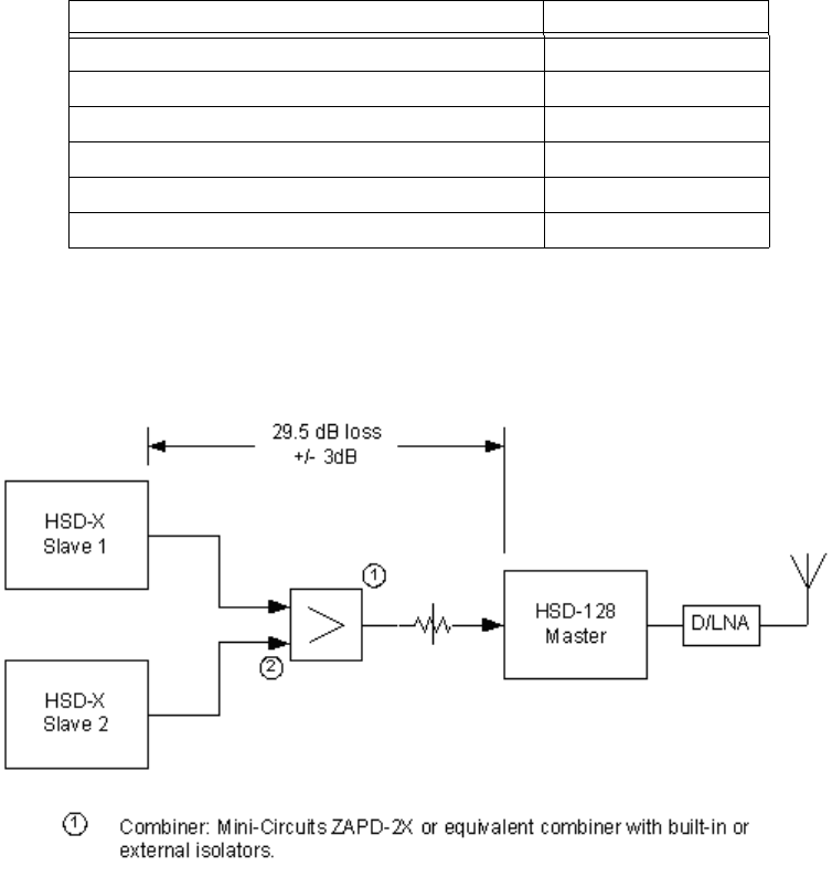
Page 3–60
18 September 2007
SYSTEM DESCRIPTION, INSTALLATION, AND MAINTENANCE MANUAL
eNfusion™ HSD-128 High-speed Data Terminal
(a) Multi-Channel Coaxial Cable Loss Considerations – Multi-Channel
When installing a Multi-Channel HSD configuration, the transmit loss between
the HSD-X slaves and the HSD-128 master must be considered. This loss, taking
into consideration the cables, the combiner, and the attenuator, should come as
close as possible to 29.5 dB (as shown in Table 3–32). For an illustrated example,
refer to Figure 3–17.
Note: The installer should try to achieve 29.5 dB loss; ± 3 dB for all HSD-X slaves.
(See Figure 3–17.) The loss is generally referred to as “HSD-X cable loss”,
even though it includes the combiner and attenuator.
Figure 3–17. HSD-X Coax Cable Loss
After installation, the actual calculated (or measured) loss between each HSD-X
and the HSD should be included in the HSD-128 ORT or EEPROM configuration.
Table 3–32. Coax Cable Losses – Multi-Channel
Item Loss (dB)
Cable, HSD-X to combiner 3
Combiner 3.5
Cable, combiner to attenuator 2
Attenuator 20
Cable, attenuator to HSD-128 1
Tota l: 2 9 .5
Page 3–61
18 September 2007
SYSTEM DESCRIPTION, INSTALLATION, AND MAINTENANCE MANUAL
eNfusion™ HSD-128 High-speed Data Terminal
(b) HSD-128 Transceiver Multi-Channel Configuration Installations
The tables in this section provide all top, middle, and bottom plug, connection
details for Stand-Alone Mode installations for the HSD-128 transceiver—specific
to Multi-Channel HSD configurations.
This section describes the general installation details and external interface
connections that are the same for all operational modes and configurations of
HSD and HSD-X transceivers.
(c) Source/Destination Identification (SDI) – Multi-Channel
Source/Destination Identification (SDI) is provided for the BSU and the HPA as
per ARINC 741 specifications. Pins marked “0” are left open circuit and pins
marked “1” are strapped on the airframe side of the connector to the pin assigned
as “SDI Common” (TP5D). For this High Gain Antenna (HGA) HPA application,
pin TP5B (“1”) should be strapped and TP5A (“0”) should be left open.
Note: The logic for the SDI/WOW is explained in ARINC 741 Characteristic
Attachment 1-4, Note 19. This SDI/WOW logic, where 0=open and
1=strapped to common, is the reverse to the logic applied to all other HSD
and HSD-X connectors, Forward ID, System Config, and Data I/O Config,
where 0=strapped to common and 1=open.
(d) Maintenance Port Interface – Multi-Channel
Both HSD and HSD-X transceivers have an RS-232 Maintenance Port interface
that provides access to a maintenance utility program for data loading, system
monitoring and testing purposes.
Access to the HSD Maintenance Utility Program is achieved by connecting an
RS-232, VT-100 terminal (PC or Laptop operating a terminal emulation program)
to the RS-232 Maintenance Port.
The HSD Maintenance port is available at the front of the HSD and at the rear
ARINC 600 connector. Connection on the front of the HSD is accessible via a
DB25S connector for local maintenance of the unit. Remote access is provided
for cases where local access is unavailable. For remote access, install an
accessible DB9S connector in the cabin area.
Direct connection to the HSD-X’s front panel, maintenance port requires an
HSD-X maintenance port cable. The front connector, maintenance port supports
trace and data load functions and is a female, micro-D-type, M83513/04-B11N,
or equivalent. As well, a permanent connector wired to the rear, middle-plug, of
the ARINC-600 connector can be installed for remote access. Specifications and
pinouts for this cable are provided in "Test and Fault Isolation" on page 4-1.
Note: The front panel and remote connections to the maintenance port cannot
be used simultaneously.
Refer to "Test and Fault Isolation" on page 4-1 for information on how to connect
and use the maintenance port—including, equipment requirements, connection
and cabling requirements, software loading instructions, and configuration
details.

Page 3–62
18 September 2007
SYSTEM DESCRIPTION, INSTALLATION, AND MAINTENANCE MANUAL
eNfusion™ HSD-128 High-speed Data Terminal
(e) Antenna Subsystem RF Interface – Multi-Channel
Several external RF parameters (such as cable losses and antenna gain), that
must be delimited to ensure proper operation, dictate the HSD performance
requirements. Table 3–33 defines these parameters and their expected values.
(f) WOW Pin Wiring – Multi-Channel
These Weight-On-Wheel (WOW) discretes are wired only if equivalent
information is not strapped as being available to the SDU on an ARINC 429 input
[for example, IRS or the Centralized Fault Display System (CFDS)].
WOW wiring, for the HSD, is optional for system operation as the HSD already
receives speed information for Doppler correction. However, if WOW wiring is
not wired, normal maintenance must be disabled when speed or Doppler
readings are greater than zero.
The WOW1 and WOW2 pins are either left open circuit or they are connected to
the airframe DC ground. The WOW Program Select (PGM) pin is either left open
circuit or is connected to the Forward Address Common. The three ground states,
defined for any pin are:
• OPN: Open circuit
• AFG: Airframe DC Ground
• FAC: Fwd Address Common (TP7K)
Resolve any conflict between WOW1 and WOW2 by assuming the aircraft is
“in-air.” The interpretation of the state of the WOW1 and WOW2 pins is defined
by the state of the WOW program select pin. Refer to Table 3–34 for details.
1. Multi-Channel Configurations
Labeled as WOW1, WOW2, and WOW Program Select, these discretes are
wired only if equivalent information is not strapped as being available to the
SDU on an ARINC 429 input [for example, IRS or the Centralized Fault
Display System (CFDS)].
Table 3–33. RF Parameters Definition – Multi-Channel
Parameter Min. Value (dB) Max. Value (dB)
Antenna Gain 8 17
Antenna—DLNA Loss 0.1 0.3
DLNA Gain 53 60
DLNA Noise Figure 1.5 1.8
DLNA—HSD-128 (BP12), including
cables and splitter (Rx) Total Loss
019
DLNA—HSD-X (BP5), including
cables and splitter (Rx) Total Loss
524
HSD-128—Antenna (Tx) Loss 1 2.5
DLNA Insertion Loss (Tx to Antenna
Port)
–0.8

Page 3–63
18 September 2007
SYSTEM DESCRIPTION, INSTALLATION, AND MAINTENANCE MANUAL
eNfusion™ HSD-128 High-speed Data Terminal
WOW wiring is optional for system operation in Stand-Alone Mode
installations as the HSD already receives speed information for Doppler
correction. However, if WOW wiring is not wired, normal maintenance must
be disabled when speed or Doppler readings are greater than zero.
(g) Forward and Return Address IDs – Multi-Channel
Figure 3–18 provides an example of a Forward ID address. The Forward ID is a
Hex number (example: $ABC123) that must be converted into a binary number
for strapping.
Table 3–34. WOW Pin Wiring Table – Multi-Channel
Pin Name and Location
WOW1 WOW2 PGM Aircraft Status
TP3G TP3H TP3J
AFG AFG FAC In-air
OPN AFG FAC Not valid – Default in-air
AFG OPN FAC Not valid – Default in-air
OPN OPN FAC On-ground
AFG AFG OPN On-ground
OPN AFG OPN Not valid – Default in-air
AFG OPN OPN Not valid – Default in-air
OPN OPN OPN In-air
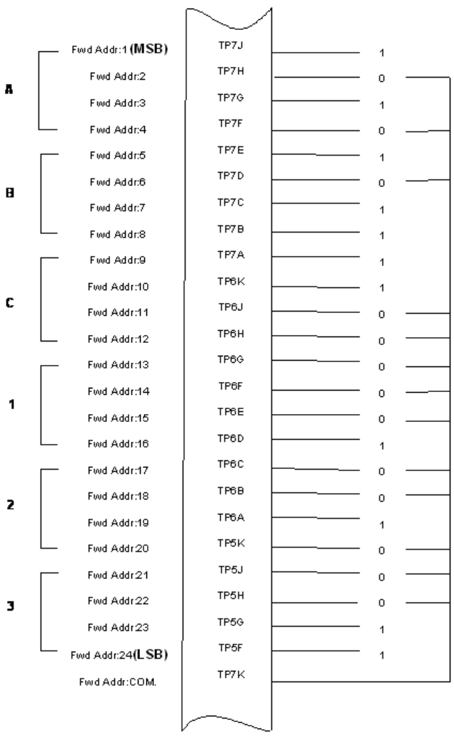
Page 3–64
18 September 2007
SYSTEM DESCRIPTION, INSTALLATION, AND MAINTENANCE MANUAL
eNfusion™ HSD-128 High-speed Data Terminal
Figure 3–18. Forward ID, Hex to Binary Conversion – Multi-Channel
Note: A pin strapped to the same potential as T7K (Forward address common)
is considered as a logical “0”, whereas an open circuit pin is considered
as a logical “1”.
Page 3–65
18 September 2007
SYSTEM DESCRIPTION, INSTALLATION, AND MAINTENANCE MANUAL
eNfusion™ HSD-128 High-speed Data Terminal
Note: MSB is the Most Significant Bit and LSB is the Least Significant Bit.
(h) Remote Status Panel – Multi-Channel (Optional)
An optional “remote status panel” may be installed in installations where the HSD
and/or any HSD-X units are located in inaccessible or remote locations. The
installation of a “remote status panel” is recommended as it provides visual
indications of each of the power, fault, and call status of each of the units.
A “remote reset switch” for HSD transceivers can also be installed and located
with the Remote Status Panel. Figure 3–19 illustrates a typical wiring diagram
for the remote reset circuit.
Note: HSD-X transceivers DO NOT support the use of the reset function.
1. HSD Remote Reset Switch Circuit Requirements
HSD transceivers support the installation of a Remote Reset Switch circuit
as shown in Figure 3–19.
The HSD Remote Reset circuit requires less than 100 ohms between TP1K
(RESET) and MP1F(COM) to be asserted and greater than 10 kilohms to be
de-asserted (include all cable and switch contact resistance).
2. HSD Remote LED Driver Circuit Requirements
The circuit requirements for the HSD Remote Status LED drivers are shown
in Figure 3–20. Each LED driver circuit has a 200-ohm current limit resistor.
The maximum cable resistance (including the forward and return paths) must
not exceed 100 ohms to provide adequate current to the 5 volt LEDs (i.e. 10
mA minimum) at the remote status panel.
It is recommended that the installer use shielded cables to provide a level of
noise immunity.
3. HSD-X Remote LED Driver Circuit Requirements
The HSD-X unit’s Remote LED drivers are shown in Figure 3–21. The open
collector transistors located in the HSD-X are capable of driving up to 500
mA of current—so either incandescent lamps or LED circuits with the
appropriate current limits can be used. The example shown in Figure 3–21
shows an LED powered with a 28-volt source.
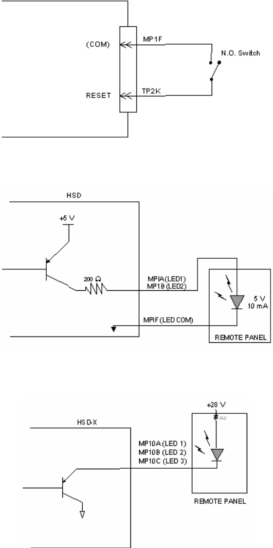
Page 3–66
18 September 2007
SYSTEM DESCRIPTION, INSTALLATION, AND MAINTENANCE MANUAL
eNfusion™ HSD-128 High-speed Data Terminal
Figure 3–19. HSD Remote Reset Circuit – Multi-Channel
Figure 3–20. HSD Remote LED Panel Circuit – Multi-Channel
Figure 3–21. HSD-X Remote Status LED Driver Circuits – Multi-Channel
Page 3–67
18 September 2007
SYSTEM DESCRIPTION, INSTALLATION, AND MAINTENANCE MANUAL
eNfusion™ HSD-128 High-speed Data Terminal
(i) User Interfaces – Multi-Channel
To facilitate user access to the HSD interfaces, install the following connectors
in the appropriate cabin area.
Note: Although the Ethernet interface is only supported by HSD-X transceivers,
HSD transceiver models, PN 1110-A-0150 and 1110-A-0160, and other
models of HSD transceivers with service bulletin 1110-SB-0004
accomplished, consider pre-wiring the cabin for all interfaces—even when
installing an HSD transceiver that currently does not support the Ethernet
interface.
1. ISDN Interface
Install an RJ-45 interface connector in the cabin area for user connections to
the ISDN interface. RJ-45 Connector Termination Details below describes the
RJ-45 connector and cable termination.
2. RS-232 Interface (MPDS)
Install a DB9S interface connector in the cabin area for connection to the
RS-232 interface. Refer to the HSD Interconnection Drawings for pinout
designation.
3. Ethernet Data Interface
HSD transceiver models, part numbers 1110-A-0150 and 1110-A-0160
support the Ethernet interface. All other models of HSD transceivers must
have service bulletin 1110-SB-0004 accomplished to support the Ethernet
interface.
All HSD-X transceivers support the Ethernet Data Interface.
Install an RJ-45 interface connector in the cabin area for user access to the
Ethernet interface. RJ-45 Connector Termination Details below describes the
RJ-45 connector and cable termination.
4. RJ-45 Connector Termination Details
Details relating to the RJ-45 cable terminations, required for both the ISDN
and/or 10BASE-T services, are shown in Table 3–35 and Figure 3–22.
Use LAN cables that meet flammability and TIA/EIA568-A CAT-5
requirements. Cables #922404(4 conductor) and # 922408 (8 conductor), as
supplied by Electronics Cable Specialists, are acceptable. Equivalent
substitutions from other manufacturers may be used.
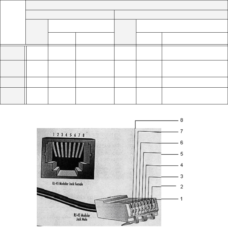
Page 3–68
18 September 2007
SYSTEM DESCRIPTION, INSTALLATION, AND MAINTENANCE MANUAL
eNfusion™ HSD-128 High-speed Data Terminal
Figure 3–22. RJ-45 Connector Terminator Details – Multi-Channel
5. System Configuration Pin Strapping – Multi-Channel
The HSD adjusts its configuration according to the status of several strap pins
on the rear ARINC 600 connector.
Configuration pins are assigned based on system-mode-configuration
selection and data input/output (I/O) requirements as shown in Table 3–36.
Detailed pin assignment is shown in Table 3–37 and Table 3–38.
Table 3–35. RJ-45 Wiring Details – Multi-Channel
Signal
SERVICE
EURO ISDN Ethernet 10BASE-T
Pin
Cable
Pin
Cable
ECS Other ECS Other
RX + 3 White White/Green 3 White White/Orange stripe
RX−6 Blue Green 6 Green Orange/White stripe or
solid Orange
TX+ 4 White Blue 1 White White/Green stripe
TX−5 Orange White/Blue 2 Brown Green/White stripe or
solid Green
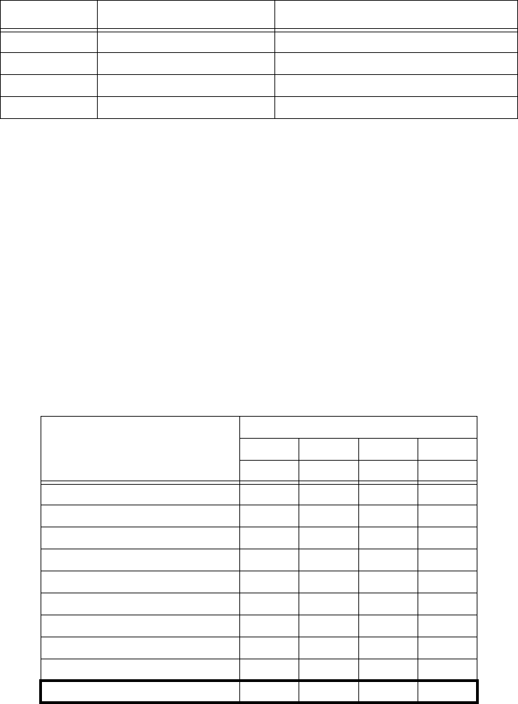
Page 3–69
18 September 2007
SYSTEM DESCRIPTION, INSTALLATION, AND MAINTENANCE MANUAL
eNfusion™ HSD-128 High-speed Data Terminal
Note: The logic for the System Configuration pins is reverse to the logic
explained in ARINC 741 Characteristic Attachment 1-4, Note 19. For
System Configuration pins, 0=strapped to common and 1=open.
• Pins marked “0” are signaled by strapping to “Fwd Address
Common” (T7K).
• Pins marked “1” are signaled by an open circuit—no connection.
• Configurations resulting in all “1’s” are invalid.
6. System Mode Strap Pins Coding – Multi-Channel
The HSD transceiver must be externally strapped according to its intended
operational configuration mode. Table 3–37 illustrates the system pin
strapping for all HSD operational modes and configurations.
Note: The logic for the System Mode pins is reverse to the logic explained
in ARINC 741 Characteristic Attachment 1-4, Note 19. For System
Mode pins, 0=strapped to common and 1=open.
• Pins marked “0” are signaled by strapping to “Fwd Address
Common” (TP7K).
Table 3–36. Configuration Pin Summary – Multi-Channel
Pin # Name Function
TP4A to D System Config #1 to #4 System Mode (See Table 3–27)
TP4E to H System Config #5 to #8 Not assigned (set to"1")
MP5G to K Data I/O Config #1 to #4 NOTE: Data I/O Mode (See Table 3–28)
MP6G to K Data I/O Config #5 to #8 Not assigned (set to"1")
Table 3–37. System Mode Pin Strapping – Multi-Channel
System Modes
Pin Status
TP4A TP4B TP4C TP4D
1234
INVALID 1111
Stand Alone 0101
Selective, SAT-906 1101
Selective, MCS-3000 1011
Selective, MCS-6000 1001
Selective, MCS-7000 0111
Honeywell Combined 1110
Reserved 1100
Collins Cooperative 0011
Multi-Channel 0001
Page 3–70
18 September 2007
SYSTEM DESCRIPTION, INSTALLATION, AND MAINTENANCE MANUAL
eNfusion™ HSD-128 High-speed Data Terminal
• Pins marked “1” are signaled by an open circuit—no connection.
• Configuration resulting in all “1’s” is Invalid.
7. User Data I/O Mode Pin Strapping – Multi-Channel
Data I/O Mode Pin strapping is only required for HSD transceivers models,
PN 1110-A-0150 and 1110-A-0160 or other HSD models that have Data I/O
Type 2 cards installed via Service Bulletin 1110-SB-0004.
The following settings allow placing restrictions on the way both channels are
used. If the user has no specific requirements then it is recommended to leave
both channels as “Unrestricted.”
In HSD transceivers with two channel cards, both channels are accessible
for Swift64 Mobile ISDN via the ISDN port on a first come-first served basis.
All four modes, as detailed in Table 3–38, are also described in Figure 3–23.
In units where all Data I/O services are available (including Ethernet), the
following statements are valid:
• The channel cards are pooled, which means that no particular card is
operated in one of the selected modes.
• If one channel card becomes inoperative, and there is a conflicting
configuration (for example, 1 Reserved, 1 SCPC – for Swift64 Mobile
ISDN), then the remaining card operates in "Unrestricted" mode.
• A “restricted” channel is not handled by the Data I/O Controller, which
results in the channel not being accessible for SCPC via Ethernet or for
MPDS via RS232 or Ethernet.
• An SCPC channel is accessible for SCPC via Ethernet.
• An MPDS channel is accessible for MPDS via RS232 and Ethernet.
• An “unrestricted” channel is accessible for SCPC via Ethernet and MPDS
via RS232 and Ethernet.
Note: Use a ”Restricted” Data I/O Mode if only ISDN service is available.

Page 3–71
18 September 2007
SYSTEM DESCRIPTION, INSTALLATION, AND MAINTENANCE MANUAL
eNfusion™ HSD-128 High-speed Data Terminal
Note: (‘0’ = FWD Address Common, ‘1’ No Connection)
Table 3–38. Data I/O Mode Pin Strapping – Multi-Channel
Pin Status Data I/O Mode
MP5G MP5H MP5J MP5K
1111Invalid
11101 Restricted, 1 Unrestricted
11011 Restricted, 1 SCPC
11001 Restricted, 1 MPDS
10112 Restricted (ISDN only)
10102 SCPC
10011 SCPC, 1 Unrestricted
10002 MPDS
01111 MPDS, 1 Unrestricted
01101 SCPC, 1 MPDS
0 1 0 1 2 Unrestricted (recommended if no specific
user requirements)
0000Reserved
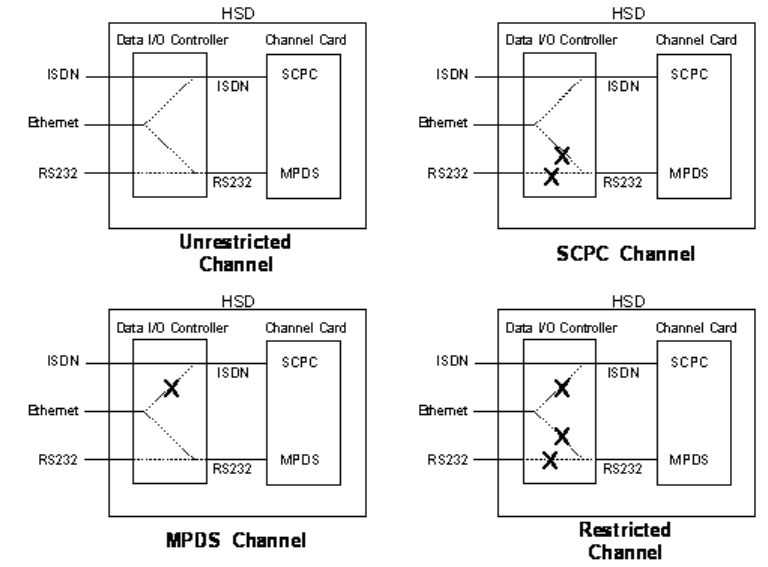
Page 3–72
18 September 2007
SYSTEM DESCRIPTION, INSTALLATION, AND MAINTENANCE MANUAL
eNfusion™ HSD-128 High-speed Data Terminal
Figure 3–23. User Data I/O Mode Configurations – Multi-Channel
(j) Multi-Channel Configuration Connection Details
The tables in this section provide all top, middle, and bottom plug connection
details for Multi-Channel Configuration installations of HSD-128 transceivers and
HSD-X transceiver extensions.

Page 3–73
18 September 2007
SYSTEM DESCRIPTION, INSTALLATION, AND MAINTENANCE MANUAL
eNfusion™ HSD-128 High-speed Data Terminal
Table 3–39. HSD-128 Multi-Channel Configuration ARINC 600 Top Plug
Connections
I/O From
Top Plug Signal Name To Description
I1A Multi-control A TP3E Multi-control from control
card
I1B Multi-control B TP3F Multi-control from control
card
I2A BSU Top/Port
BITE A
(See Note 1)
Mech. Steered Antenna
(MA): BSU, Pin G1 or W or
Other Antenna2 (OA):
BSU,
PORT-W & Starboard-P
ARINC Tx-HI BITE from
Top/Port BSU
I2B BSU Top/Port
BITE B
MA: BSU, Pin H or X, or
OA: BSU, PORT-X &
STBD-R
ARINC Tx-LO BITE from
Top/Port BSU
I2C BSU Starboard
(STBD) BITE A
MA: Not required
OA: BSU, PORT-P &
STBD-W
ARINC Tx-HI BITE from
STBD BSU
I2D BSU STBD BITE
B
MA: Not required
OA: BSU, PORT-R &
STBD-X
ARINC Tx-LO BITE from
STBD BSU
I3A Top/Port HPA
MUTE A
MA: Not required
OA: BSU, PORT-G
HPA Mute-A, Port BSU
I3B Top/Port HPA
MUTE B
MA: Not required
OA: BSU, PORT-H
HPA Mute-B, Port BSU
I3C STBD HPA
MUTE A
MA: Not required
OA: BSU, STBD G
HPA Mute-A, STBD BSU
I3D STBD HPA
MUTE B
MA: Not required
OA: BSU, STBD-H
HPA Mute-B, STBD BSU
O3E OUT
Multi-Control A
IN Multi Ctrl A (TP1A), and
MA: BSU, Pin A or T, or
OA: BSU, PORT-T &
STBD-T
Multi-Control-HI to HSD &
Antenna Subsystem
O2E A OUT All slave HSD-Xs TP6A ARINC 429 Tx-HI HSD-X
crosstalk broadcast
O2F B OUT All slave HSD-Xs TP6B ARINC 429 Tx-Lo HSD-X
crosstalk broadcast
I2H A IN HSD-X slave 1 TP6C ARINC 429 Tx-HI HSD-X
crosstalk chain
I2J B IN HSD-X slave 1 TP6D ARINC 429 Tx-Lo HSD-X
crosstalk chain

Page 3–74
18 September 2007
SYSTEM DESCRIPTION, INSTALLATION, AND MAINTENANCE MANUAL
eNfusion™ HSD-128 High-speed Data Terminal
O3F OUT
Multi-Control B
IN Multi Ctrl B (TP1B), and
MA: BSU, Pin B or U, or
OA: BSU, PORT-U &
STBD-U
Multi-Control-LO to HSD
& Antenna Subsystem
I2K Remote Reset Normally open
momentary switch—open
side. (Closed side to
MP1F)
Remote System Reset
I3G WOW 1 TP3G Weight On Wheel, as
defined in Note 40 of
ARINC 741, Part 1.
I3H WOW 2 TP3H
I3J WOW Program
Select
TP3J
I4A, 4B,
4C, 4D
System Config 1
to 4
4A, 4B, & 4C=0 (TP7K
common)
4D=1(Open)
Multi-Channel Mode
Configurations
I4E to 4H System Config 5
to 8
Open (1) System Configuration -
not assigned
I4J IRS-A Aircraft main IRS IRS 429 Data, Rx HI
I4K IRS-B Aircraft main IRS IRS 429 Data, Rx LO
I5A SDI 1 Not connected HPA Select Code for HGA
I5B SDI 2 SDI common (TP5D) HPA Select Code for HGA
I5D SDI Common SDI 2 (TP5B) SDI Common for HPA
select codes
I5F FWD Address,
BIT 24 (LSB)
1=no connection,
0=Common (TP7K)
Six digit Hex ID assigned
by Inmarsat /EMS
SATCOM
I5G FWD Address,
I5H FWD Address,
I5J FWD Address,
I5K FWD Address,
BIT 20
I6A FWD Address,
I6B FWD Address,
I6C FWD Address,
I6D FWD Address,
I6E FWD Address,
Table 3–39. HSD-128 Multi-Channel Configuration ARINC 600 Top Plug
Connections
I/O From
Top Plug Signal Name To Description

Page 3–75
18 September 2007
SYSTEM DESCRIPTION, INSTALLATION, AND MAINTENANCE MANUAL
eNfusion™ HSD-128 High-speed Data Terminal
1BSU Pin nomenclature for Mechanically-Steered Antennae (MA) is manufacturer dependent.
2“Other antenna types” (OA) represent either conformal or phased array antennae.
I6F FWD Address,
I6G FWD Address,
I6H FWD Address,
I6J FWD Address,
I6K FWD Address,
I7A FWD Address,
I7B FWD Address,
I7C FWD Address,
I7D FWD Address,
I7E FWD Address,
I7F FWD Address,
I7G FWD Address,
I7H FWD Address,
I7J FWD Address,
BIT 1 (MSB)
I7K FWD Address,
Common
Common GND
connection for system and
I/O configuration and
IC1 RF in Tx Attenuator, from HSD-X
slaves
Coax Cable, RF Transmit
Table 3–40. HSD-128 Multi-Channel Configuration, ARINC 600 Middle Plug
Connections
I/O
From
Middle
Plug
Signal Name To Description
O1A LED 1 Remote Status Panel—
Green
HSD—Power On
O1B LED 2 Remote Status Panel—
Red
HSD—Fault
Table 3–39. HSD-128 Multi-Channel Configuration ARINC 600 Top Plug
Connections
I/O From
Top Plug Signal Name To Description

Page 3–76
18 September 2007
SYSTEM DESCRIPTION, INSTALLATION, AND MAINTENANCE MANUAL
eNfusion™ HSD-128 High-speed Data Terminal
O1F LED Common Remote Status LED
Panel, and closed side of
N.O. Remote Reset
Switch
LED Common
O1G Maint Port Tx
(OUT)
Maint Port serial data,
DB9S-2
Maintenance computer,
for “Remote” access
I1H Maint Port Rx (IN) Maint Port serial data,
DB9S-3
I/
O
1J Maint Port Signal
Ground.
Maint Port serial data,
DB9S-5
O3A CC (channel
card)#2 Rx
DTE-1B, DB9S-2 or
DB25P-3
User Mobile Packet Data
(MPDS), RS-232,
DTE-1B
I3B CC #2 Tx DTE-1B, DB9S-3 or
DB25P-2
I3C CC #2 RTS DTE-1B, DB9S-7 or
DB25P-4
O3D CC #2 CTS DTE-1B, DB9S-8 or
DB25P-5
I3E CC #2 DTR DTE-1B, DB9S-4 or
DB25P-20
O3F CC #2 DSR DTE-1B, DB9S-6 or
DB25P-6
O3G CC #2 CD DTE-1B, DB9S-1 or
DB25P-8
O3H CC #2 RI DTE-1B, DB9S-9 or
DB25P-22
I/
O
3J CC #2 SGND DTE-1B, DB9S-5 or
DB25P-7
I4G BRI Rx+ISDN, RJ45-3 User Data, ISDN–2
Refer to "User Interfaces
– Multi-Channel" on page
3-67
I4H BRI Rx-ISDN, RJ45-6
O4J BRI Tx+ISDN, RJ45-4
O4K BRI Tx-ISDN, RJ45-5
I5G to 5K I/O CONFIG Pins
1 to 4
See Figure 3–8 System Data I/O Mode
Configurations
Table 3–40. HSD-128 Multi-Channel Configuration, ARINC 600 Middle Plug
Connections
I/O
From
Middle
Plug
Signal Name To Description

Page 3–77
18 September 2007
SYSTEM DESCRIPTION, INSTALLATION, AND MAINTENANCE MANUAL
eNfusion™ HSD-128 High-speed Data Terminal
I6G to 6K I/O CONFIG 5 to 8 Open (1) System Data I/O
Configurations – not
assigned
I6A BRI Rx+ISDN, RJ45-3 User Data, ISDN–1
Refer to "User Interfaces
– Multi-Channel" on page
3-67
I6B BRI Rx -ISDN, RJ45-6
O6C BRI Tx+ISDN, RJ45-4
O6D BRI Tx-ISDN, RJ45-5
I7A 10BASE-T Rx+Ethernet 10BASE-T,
RJ45-3
User Data, Ethernet
10BASE-T
I7B 10BASE-T Rx-Ethernet 10BASE-T,
RJ45-6
O7C 10BASE-T Tx+Ethernet 10BASE-T,
RJ45-1
O7D 10BASE-T Tx-Ethernet 10BASE-T,
RJ45-2
OC1 RF, Tx Output Antenna
Subsystem-DLNA-J3
Coax Cable, RF Transmit
Table 3–41. HSD-128 Multi-Channel Configuration ARINC 600 Bottom Plug
Connections
I/O
From
Bottom
Plug
Signal Name To Description
I2 +28 V dc HOT Aircraft Power Source,
HOT
+28 V dc supply
I3 +28 V dc return GND Aircraft Power Source,
return
I8 Chassis GND Aircraft Ground Aircraft Chassis Ground
I1 115 V ac HOT Aircraft Power Source,
HOT
115 V ac 400 Hz supply
I7 115 V ac COLD Aircraft Power Source,
COLD
I12 RF Rx Input Splitter output from
Antenna
Subsystem –DLNA
Coax Cable, RF Receive
Table 3–40. HSD-128 Multi-Channel Configuration, ARINC 600 Middle Plug
Connections
I/O
From
Middle
Plug
Signal Name To Description

Page 3–78
18 September 2007
SYSTEM DESCRIPTION, INSTALLATION, AND MAINTENANCE MANUAL
eNfusion™ HSD-128 High-speed Data Terminal
(k) HSD-X Installations – Multi-Channel
The tables in this section provide all top, middle, and bottom plug, connection
details for of HSD-Xs integrated with the HSD-128 transceiver in Multi-Channel
configurations.
Table 3–42. HSD-X Top Plug Connections
I/O
From
Top
Plug
Signal Name To Description
I4A, 4B,
4C, 4D
System
Configuration 1 to 4
4A, 4B, 4C, 4D = 1 (Open) System Configuration
Reserved
I
6A HSD-X/HSD I/F
Bus A In
HSD-128 Master TP2E ARINC 429 Rx-HI
Master Crosstalk
Broadcast
I
6B HSD-X/HSD I/F
Bus B In
HSD-128 Master TP2F ARINC 429 Rx-LO
Master Crosstalk
Broadcast
O
6C HSD-X/HSD I/F
Bus A Out
Refer to the
interconnection diagram
1110-B-0419
ARINC 429 Tx-HI
HSD-X Crosstalk Ring
O
6D HSD-X/HSD I/F
Bus B Out
Refer to the
interconnection diagram
1110-B-0419
ARINC 429 Tx-LO
HSD-X Crosstalk Ring
I
8A Input Bus A In Refer to the
interconnection diagram
1110-B-0419
ARINC 429 Rx-HI
HSD-X Crosstalk Ring
I
8B Input Bus B In Refer to the
interconnection diagram
1110-B-0419
ARINC 429 Rx-LO
HSD-X Crosstalk Ring
I
9D Fwd ID Common Common GND
connection for system,
I/O configuration, and
FWD ID
I10A Fwd ID #1 (MSB) 1 = no connection,
0 = common (TP9D)
Six digit Hex ID assigned
by Inmarsat / EMS
SATCOM
I10B Fwd ID #2
I10C Fwd ID #3
I10D Fwd ID #4
I11A Fwd ID #5
I11B Fwd ID #6
I11C Fwd ID #7
I11D Fwd ID #8
I12A Fwd ID #9
I12B Fwd ID #10
I12C Fwd ID #11
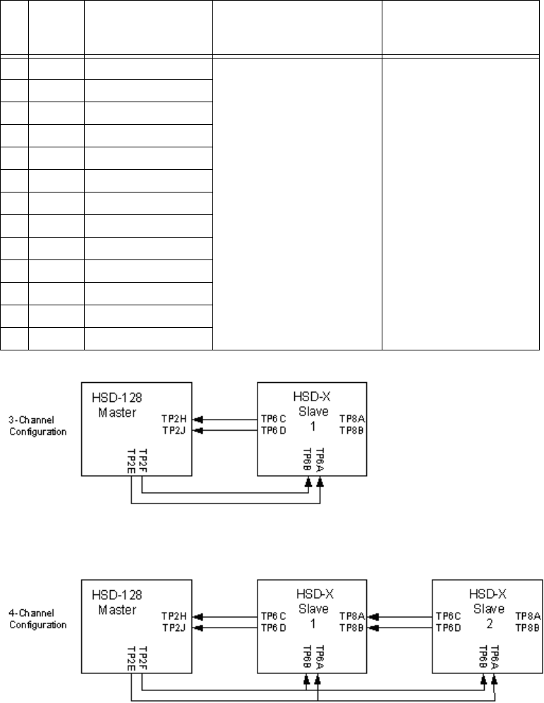
Page 3–79
18 September 2007
SYSTEM DESCRIPTION, INSTALLATION, AND MAINTENANCE MANUAL
eNfusion™ HSD-128 High-speed Data Terminal
Figure 3–24. HSD-X Top Plug Connections (Illustrated)
I12D Fwd ID #12
I13A Fwd ID #13
I13B Fwd ID #14
I13C Fwd ID #15
I13D Fwd ID #16
I14A Fwd ID #17
I14B Fwd ID #18
I14C Fwd ID #19
I14D Fwd ID #20
I15A Fwd ID #21
I15B Fwd ID #22
I15C Fwd ID #23
I15D Fwd ID #24 (LSB)
Table 3–42. HSD-X Top Plug Connections
I/O
From
Top
Plug
Signal Name To Description

Page 3–80
18 September 2007
SYSTEM DESCRIPTION, INSTALLATION, AND MAINTENANCE MANUAL
eNfusion™ HSD-128 High-speed Data Terminal
Table 3–43. HSD-X Middle Plug Connections– Multi-Channel
I/O
From
Middle
Plug
Signal Name To Description
O1A Maint Port Tx Maint Port serial data,
DB9S-2
Maintenance Computer,
for “Remote” access,
RS-232
I1B Maint Port Rx Maint Port serial data,
DB9S-3
I1C Maint Port GND Maint Port serial data,
DB9S-5
I1D MPDS SGND DTE-1, DB9S-5 or
DB25P-7
User Mobile Packet Data
(MPDS), RS-232,
DTE-1A
O2A MPDS Rx DTE-1, DB9S-2 or
DB25P-3
I2B MPDS Tx DTE-1, DB9S-3 or
DB25P-2
I2C MPDS RTS DTE-1, DB9S-7 or
DB25P-4
O2D MPDS CTS DTE-1, DB9S-8 or
DB25P-5
I3C MPDS DTR DTE-1, DB9S-4 or
DB25P-20
O3D MPDS DSR DTE-1, DB9S-6 or
DB25P-6
O4C MPDS CD DTE-1, DB9S-1 or
DB25P-8
O4D MPDS RI DTE-1, DB9S-9 or
DB25P-22
O10A Channel Available Discrete Channel Available
O10B Service Ready Discrete System ready
O
10C HSD-X Fail Discrete An “ON” state indicates
that the HSD-X LRU has
failed
I
10D Transmit Disable Discrete An “ON” state commands
the HSD-X LRU to turn off
its transmit carrier.
I11A to
11C
I/O Config 1 to 3 As per 245 System Data I/O Mode
Configurations
I13A ISDN BRI RX+ ISDN, RJ45-3 User Data, ISDN-1
Refer to "User Interfaces
– Multi-Channel" on page
3-67
I13B ISDN BRI RX- ISDN, RJ45-6
O13C ISDN BRI TX+ ISDN, RJ45-4
O13D ISDN BRI TX- ISDN, RJ45-5

Page 3–81
18 September 2007
SYSTEM DESCRIPTION, INSTALLATION, AND MAINTENANCE MANUAL
eNfusion™ HSD-128 High-speed Data Terminal
Note: MP11D: Reserved, 0 = FWD Address Comm
I15A 10BASE-T RX+ Ethernet 10BASE-T,
RJ45-3
User Data, Ethernet
10BASE-T
I15B 10BASE-T RX- Ethernet 10BASE-T,
RJ45-6
O15C 10BASE-T TX+ Ethernet 10BASE-T,
RJ45-1
O15D 10BASE-T TX- Ethernet 10BASE-T,
RJ45-2
Table 3–44. HSD-X Bottom Plug – Multi-Channel
I/O
From
Bottom
Plug
Signal Name To Description
O 1 RF, Tx Output Combiner to HSD-128 Coax Cable, RF
Transmit
I 2 115 V ac HOT Aircraft Power Source,
HOT
115 V ac 400 Hz supply
I 3 Chassis GND Aircraft Ground Aircraft Chassis Ground
I 4 115 V ac COLD Aircraft Power Source,
COLD
115 V ac 400 Hz supply
I 5 RF Rx Input Splitter from Antenna
Subsystem-DLNA
Coax Cable, RF Receive
Table 3–45. HSD-X I/O Data Strapping– Multi-Channel
MP11A MP11B MP11C I/O Config
111Invalid
110Restricted (disable Data I/O)
101MPDS (Future)
100SCPC (M4) only
011Unrestricted (recommended if there are no specific
user requirements)
010Not Assigned
001Not Assigned
000Reserved
Table 3–43. HSD-X Middle Plug Connections– Multi-Channel
I/O
From
Middle
Plug
Signal Name To Description

Page 3–82
18 September 2007
SYSTEM DESCRIPTION, INSTALLATION, AND MAINTENANCE MANUAL
eNfusion™ HSD-128 High-speed Data Terminal
Table 3–46. Inter-LRU RF Connection Considerations for Attenuators–
Multi-Channel
Function From To Frequency (MHz) Loss VSWR
HSD-X1 Tx HSD-X1 BP1 HSD-128 TPC1 1626.5-1660.5 29.5dB ±
3.0dB
1.5:1, max
HSD-X2 Tx HSD-X2 BP1 HSD-128 TPC1 1626.5-1660.5 29.5dB ±
3.0dB
1.5:1, max
HSD-X1 Rx DLNA HSD-X1 BP5 1525.0-1559.0 5.0dB to
24.0dB
1.5:1, max
HSD-X2 Rx DLNA HSD-X2 BP5 1525.0-1559.0 5.0dB to
24.0 dB
1.5:1, max
HSD-128 Rx DLNA HSD-128 BP12 1525.0-1559.0 0.0dB to
19.0dB
1.5:1, max
Page 3–83
18 September 2007
SYSTEM DESCRIPTION, INSTALLATION, AND MAINTENANCE MANUAL
eNfusion™ HSD-128 High-speed Data Terminal
9. Outline/Installation and Interconnection/Contact Assignment Diagrams
This section contains the outline and installation drawings and interconnection and contact
assignment diagrams for all installation modes and configurations of HSD and HSD-X
transceivers.
All foldout pages are odd-numbered and “not-backed” for print production purposes.
A. Outline/Installation Diagrams
Figure 3–25 and Figure 3–26 illustrate the physical characteristics of the HSD transceiver
and provides installation data for the unit.
Figure 3–27 and Figure 3–28 illustrate the physical characteristics of the HSD-X
transceiver and provides installation data for the unit.
B. Interconnection/Contact Assignment Drawings
Figure 3–29 illustrates the interconnection details for Stand-Alone Mode HSD
Transceivers.
Figure 3–30 provides the contact assignments for Stand-Alone Mode HSD Transceivers.
Figure 3–31 illustrates the interconnection details for Combined/Selective Mode HSD
Transceivers.
Figure 3–32 provides the contact assignments for Combined/Selective Mode HSD
Transceivers.
Figure 3–33 illustrates the interconnection details for Cooperative Mode HSD
Transceivers.
Figure 3–34 provides the contact assignments for Cooperative Mode HSD Transceivers.
Figure 3–35 and Figure 3–36 illustrate the interconnection details for Multi-Channel HSD
configurations.
Figure 3–37 and Figure 3–38 provide the contact assignments for Multi-Channel HSD
configurations.
Page 3–84
18 September 2007
SYSTEM DESCRIPTION, INSTALLATION, AND MAINTENANCE MANUAL
eNfusion™ HSD-128 High-speed Data Terminal
Blank Page
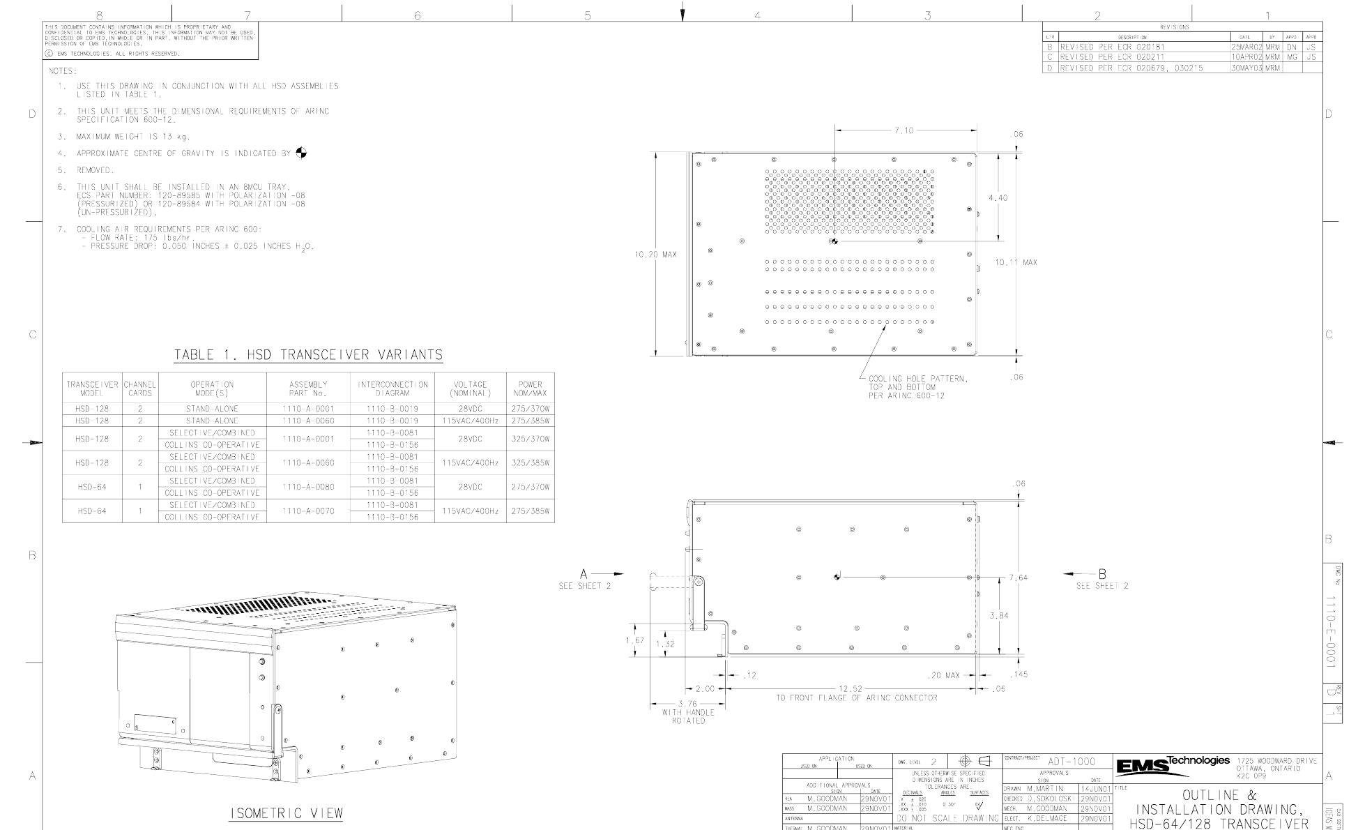
Page 3–85 / blank back
18 September 2007
SYSTEM DESCRIPTION, INSTALLATION, AND MAINTENANCE MANUAL
eNfusion™ HSD-128 High-speed Data Terminal
Figure 3–25 (Sheet 1). HSD Outline and Installation Drawing - 1110-E-0001, Rev D
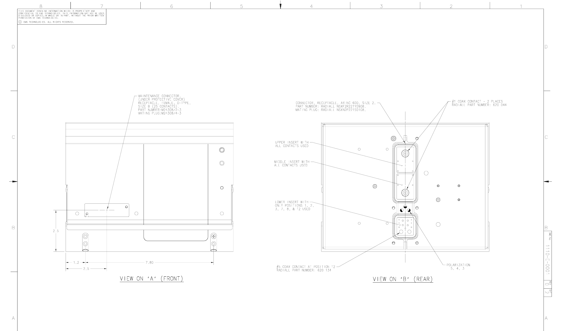
Page 3–87 / blank back
18 September 2007
SYSTEM DESCRIPTION, INSTALLATION, AND MAINTENANCE MANUAL
eNfusion™ HSD-128 High-speed Data Terminal
Figure 3–26 (Sheet 2). HSD Outline and Installation Drawing - 1110-E-0001, Rev D
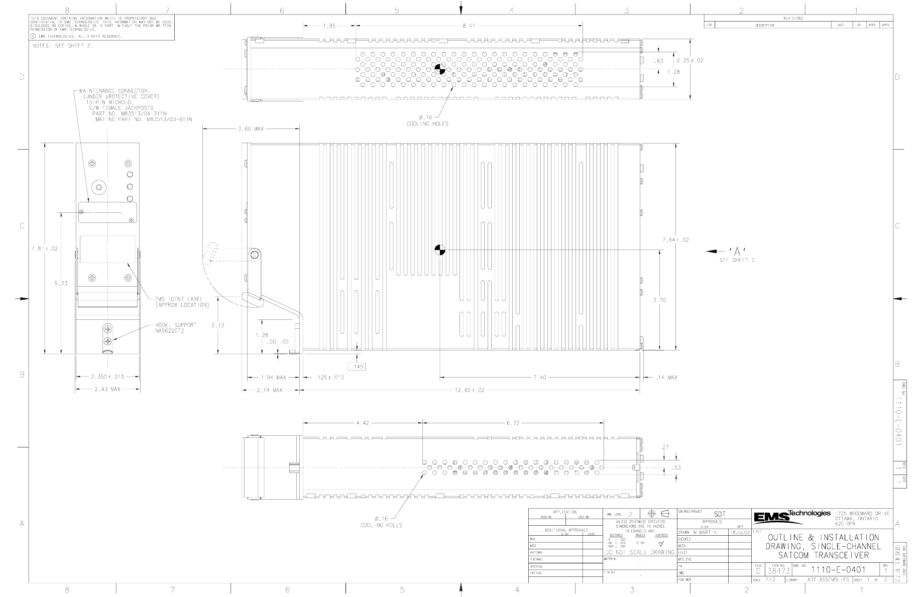
Page 3–89 / blank back
18 September 2007
SYSTEM DESCRIPTION, INSTALLATION, AND MAINTENANCE MANUAL
eNfusion™ HSD-128 High-speed Data Terminal
Figure 3–27 (Sheet 1). HSD-X Outline and Installation Drawing - 1110-E-0401, Rev 1
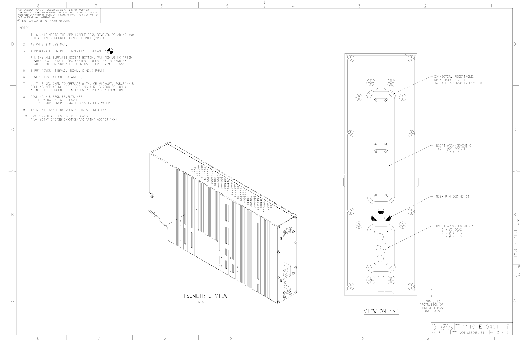
Page 3–91 / blank back
18 September 2007
SYSTEM DESCRIPTION, INSTALLATION, AND MAINTENANCE MANUAL
eNfusion™ HSD-128 High-speed Data Terminal
Figure 3–28 (Sheet 2). HSD-X Outline and Installation Drawing - 1110-E-0401, Rev 1
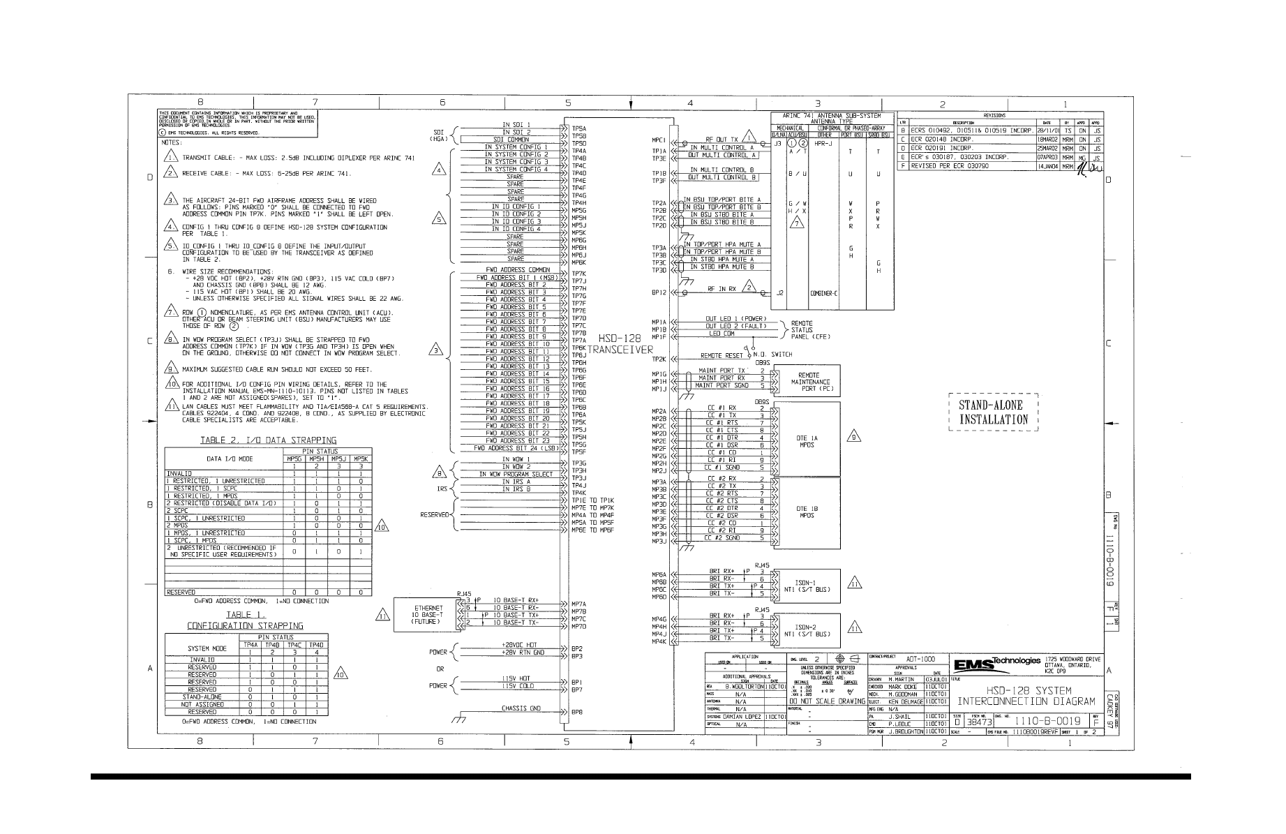
Page 3–93 / blank back
18 September 2007
SYSTEM DESCRIPTION, INSTALLATION, AND MAINTENANCE MANUAL
eNfusion™ HSD-128 High-speed Data Terminal
Figure 3–29 (Sheet 1). Stand-Alone Mode HSD System Interconnection Diagram - 1110-B-0019, Rev F
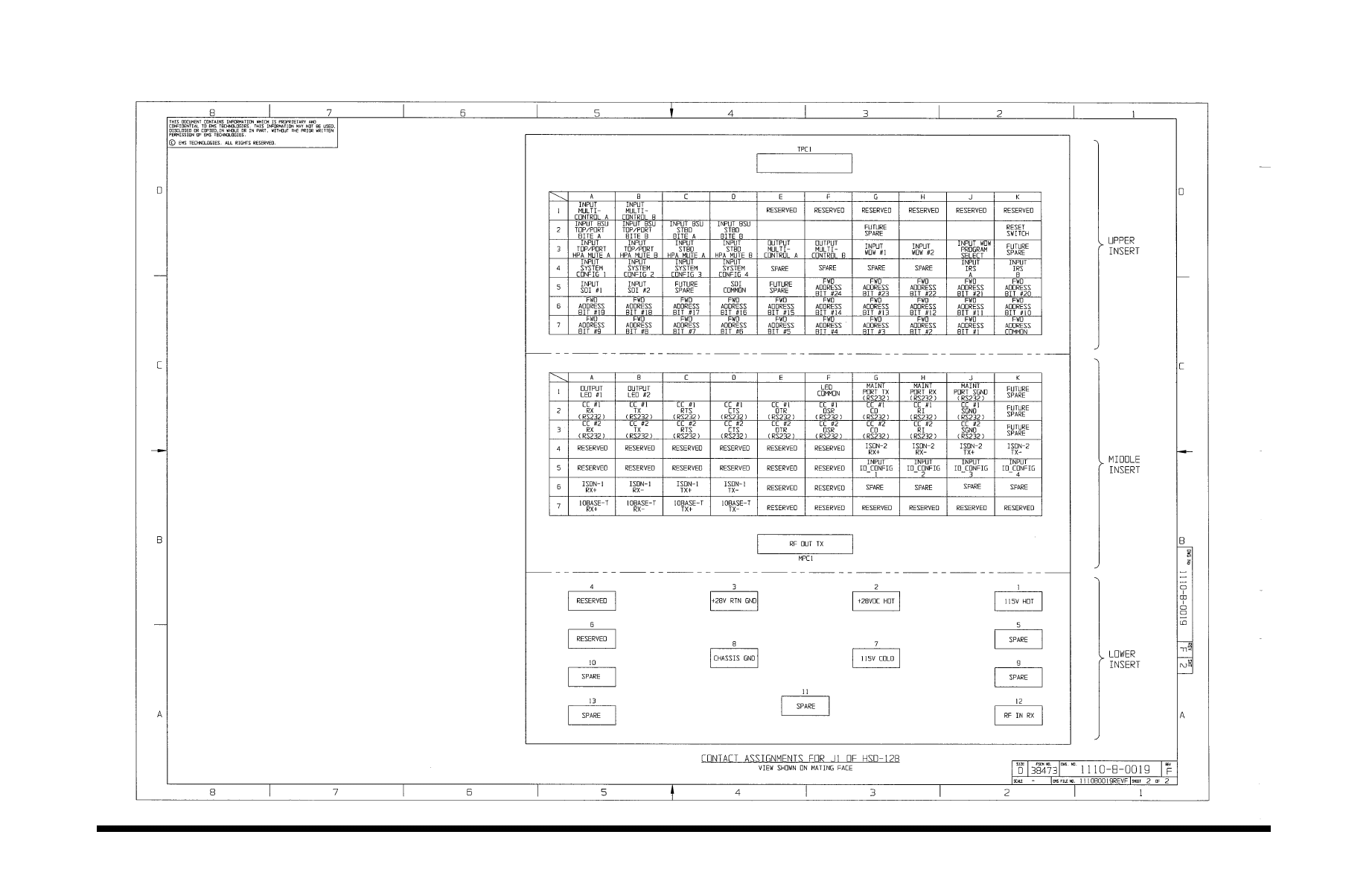
Page 3–95 / blank back
18 September 2007
SYSTEM DESCRIPTION, INSTALLATION, AND MAINTENANCE MANUAL
eNfusion™ HSD-128 High-speed Data Terminal
Figure 3–30 (Sheet 2). Stand-Alone Mode HSD System Interconnection Diagram - 1110-B-0019, Rev F
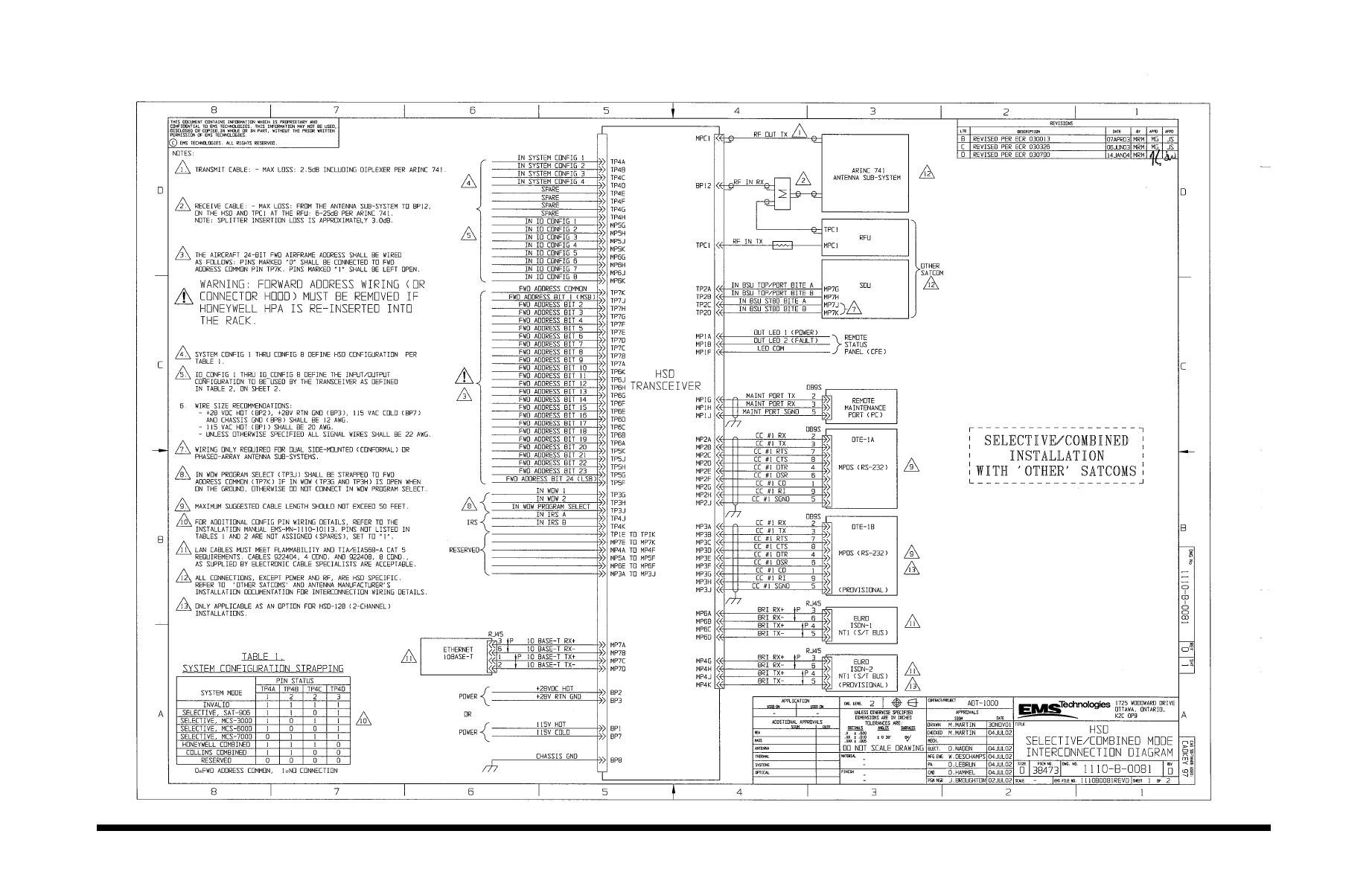
Page 3–97 / blank back
18 September 2007
SYSTEM DESCRIPTION, INSTALLATION, AND MAINTENANCE MANUAL
eNfusion™ HSD-128 High-speed Data Terminal
Figure 3–31 (Sheet 1). HSD Selective/Combined Mode Interconnection Diagram - 1110-B-0081, Rev D

Page 3–99 / blank back
18 September 2007
SYSTEM DESCRIPTION, INSTALLATION, AND MAINTENANCE MANUAL
eNfusion™ HSD-128 High-speed Data Terminal
Figure 3–32 (Sheet 2). HSD Selective/Combined Mode Interconnection Diagram - 1110-B-0081, Rev D
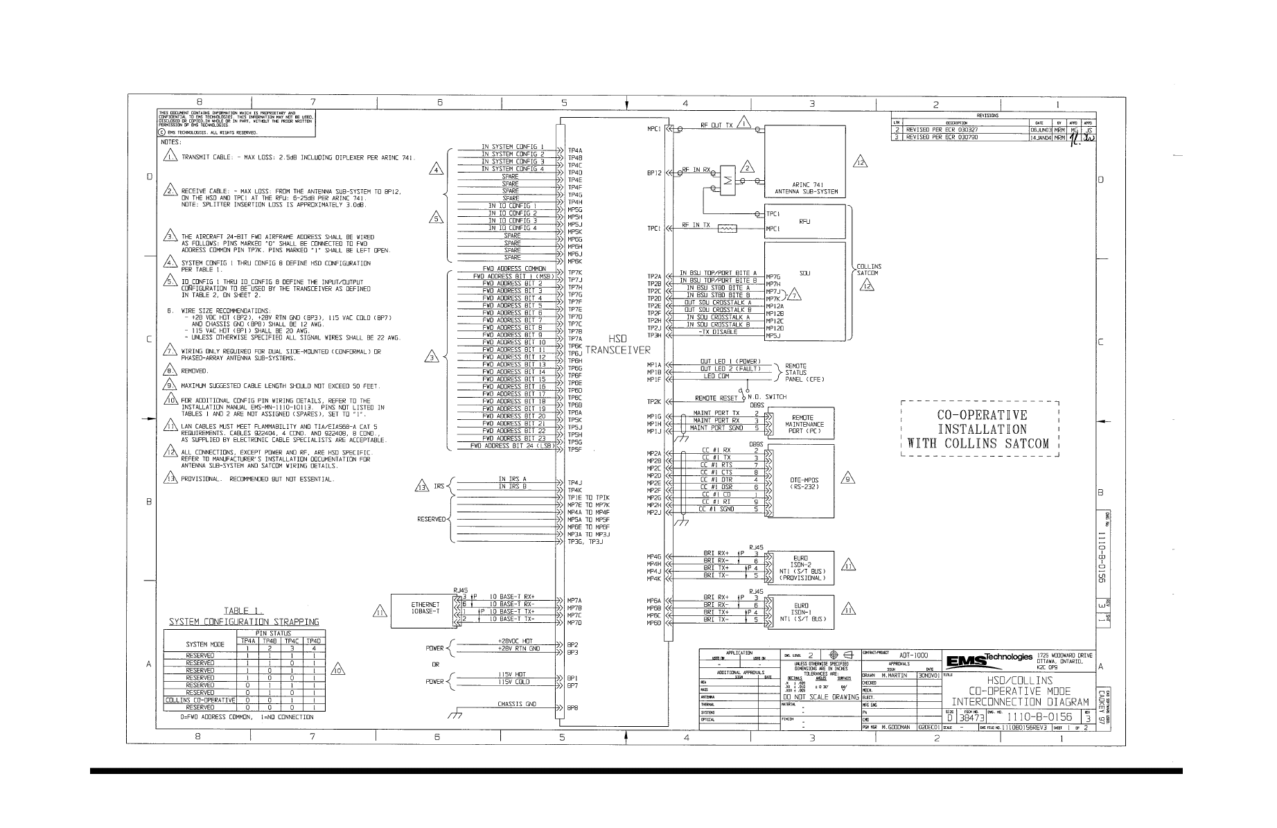
Page 3–101 / blank back
18 September 2007
SYSTEM DESCRIPTION, INSTALLATION, AND MAINTENANCE MANUAL
eNfusion™ HSD-128 High-speed Data Terminal
Figure 3–33 (Sheet 1). HSD Cooperative Mode Interconnection Diagram - 1110-B-0156, Rev 3
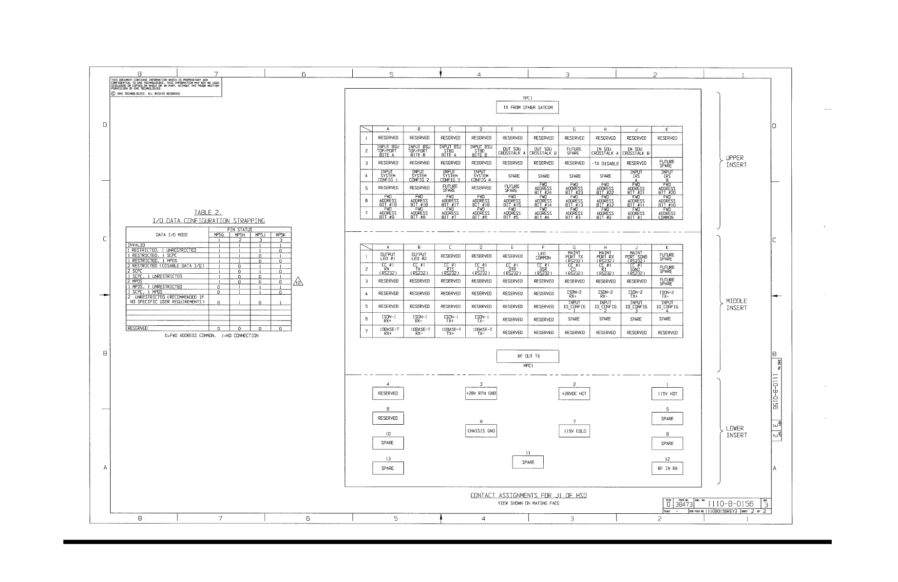
Page 3–103 / blank back
18 September 2007
SYSTEM DESCRIPTION, INSTALLATION, AND MAINTENANCE MANUAL
eNfusion™ HSD-128 High-speed Data Terminal
Figure 3–34 (Sheet 2). HSD Cooperative Mode Interconnection Diagram - 1110-B-0156, Rev 3
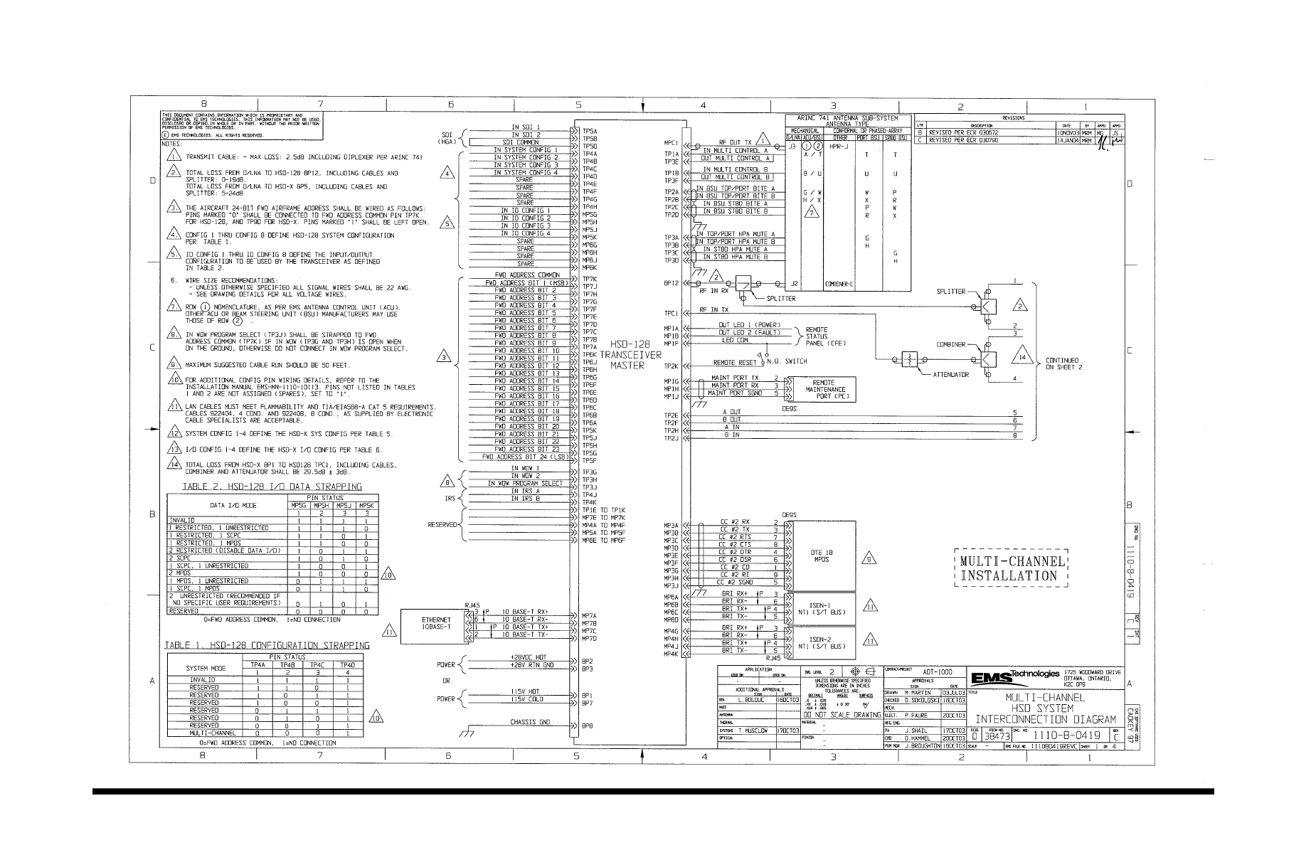
Page 3–105 / blank back
18 September 2007
SYSTEM DESCRIPTION, INSTALLATION, AND MAINTENANCE MANUAL
eNfusion™ HSD-128 High-speed Data Terminal
Figure 3–35 (Sheet 1). HSD-128 Multi-Channel Interconnection Diagram - 1110-B-0419, Rev C
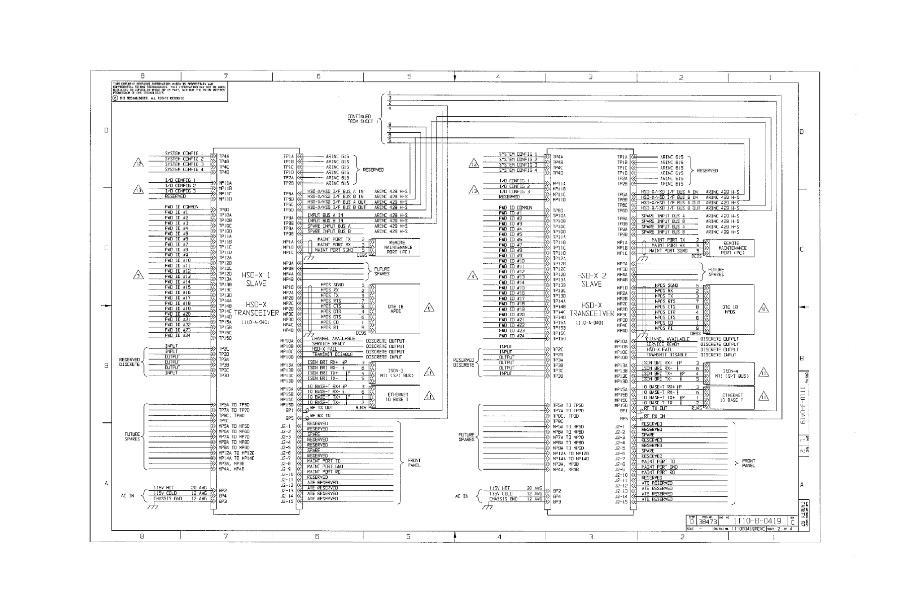
Page 3–107 / blank back
18 September 2007
SYSTEM DESCRIPTION, INSTALLATION, AND MAINTENANCE MANUAL
eNfusion™ HSD-128 High-speed Data Terminal
Figure 3–36. (Sheet 2). HSD-128 Multi-Channel Interconnection Diagram - 1110-B-0419, Rev C
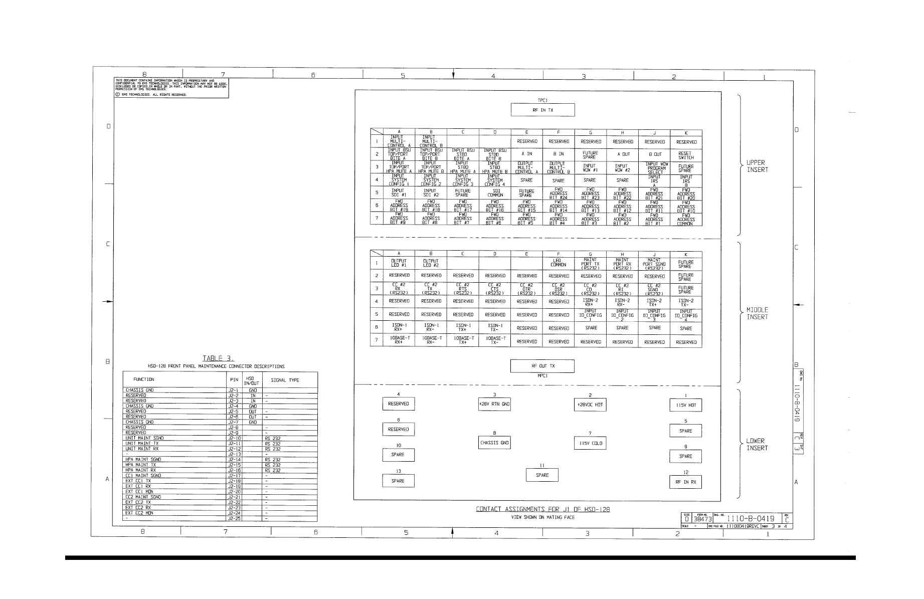
Page 3–109 / blank back
18 September 2007
SYSTEM DESCRIPTION, INSTALLATION, AND MAINTENANCE MANUAL
eNfusion™ HSD-128 High-speed Data Terminal
Figure 3–37 (Sheet 3). HSD-128 Multi-Channel Interconnection Diagram - 1110-B-0419, Rev C
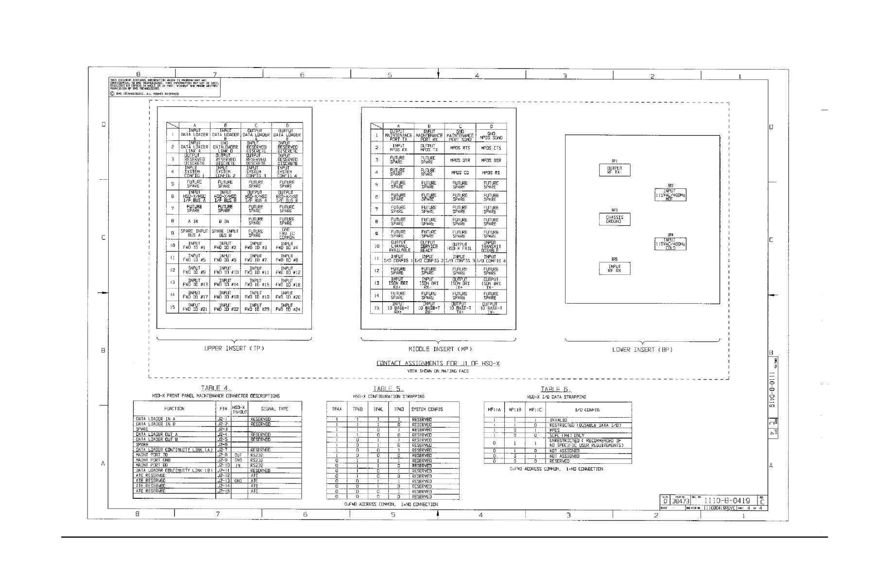
Page 3–111 / blank back
18 September 2007
SYSTEM DESCRIPTION, INSTALLATION, AND MAINTENANCE MANUAL
eNfusion™ HSD-128 High-speed Data Terminal
Figure 3–38 (Sheet 4). HSD-128 Multi-Channel Interconnection Diagram - 1110-B-0419, Rev C
Page 4–1
18 September 2007
SYSTEM DESCRIPTION, INSTALLATION, AND MAINTENANCE MANUAL
eNfusion™ HSD-128 High-speed Data Terminal
TEST AND FAULT ISOLATION
1. Introduction
This section provides the information required to determine the operational readiness of the
HSD and HSD-X transceivers and to aid service personnel in diagnosing system faults.
The operational and diagnostic tests described in this section require using the HSD and
HSD-X transceivers built-in diagnostic tool referred to as the HSD maintenance utility program.
This section provides detailed descriptions of the HSD maintenance utility program menus,
reports, and basic user instructions. Refer to page "HSD Maintenance Utility Program" on
page 4-3 for maintenance port cabling details.
Note: Depending on the version of software installed, the maintenance utility program report
and menu screens displayed may differ from those shown as examples in this manual.

Page 4–2
18 September 2007
SYSTEM DESCRIPTION, INSTALLATION, AND MAINTENANCE MANUAL
eNfusion™ HSD-128 High-speed Data Terminal
2. Operational and Diagnostic Testing
A. General
Usually, units require testing for one of the reasons listed below:
• To verify the operational readiness of the unit during and after installation on an aircraft.
• To verify that a fault exists and produce system reports for troubleshooting purposes.
• To verify the operational readiness of repaired LRUs during re-installation on an
aircraft.
This section presents software loading and test and fault isolation procedures for the HSD
and HSD-X transceivers. All test and load procedures require using the HSD maintenance
utility program, which is accessed by connecting to the maintenance port of the unit.
B. Test and Fault Isolation Equipment Requirements
Table 4–1 lists the equipment required to access the HSD maintenance utility program
and perform operational and diagnostic testing and software loads on the HSD and HSD-X
transceivers.
Table 4–2 lists the optional equipment or information that, although not required, may
increase test efficiency or allow for optional diagnostic procedures. Equivalent
substitutions may be used.
Table 4–1. List of Required Test Equipment
Item Equipment Specification Quantity
Computer Standard VT-100 386 CPU, 20-MHz or
higher
1
VT-100 terminal
emulation program
HyperTerminal©,
ProComm Plus©, or
equivalent
Serial communication
program using an RS-232 port
1
Cable, maintenance
port interface cable
Special
HSD units (See
Figure 4–3)
HSD-X units (See
Figure 4–4)
Remote access: maximum
length 25 ft (Measured from
the ARINC 600 connector to
the DB9 breakout connector)
Front Panel access:
maximum length 50 ft
1
Multimeter Standard – 1
General purpose
toolset
Standard – 1
Software load program Special PN 1110-SW-1021 1
HSD/HSD-X software
files
Special As specified in applicable
service bulletins
As
required

Page 4–3
18 September 2007
SYSTEM DESCRIPTION, INSTALLATION, AND MAINTENANCE MANUAL
eNfusion™ HSD-128 High-speed Data Terminal
C. HSD Maintenance Utility Program
This section describes the HSD maintenance port utility program and provides the
connection and cabling details required to access and use the program.
(1) General Overview
A maintenance utility program, built into the HSD and HSD-X transceiver’s operational
software, provides a system interface for fault isolation and diagnostic procedures.
Connection to this program is made through the RS-232 maintenance port interface.
To use the HSD Maintenance Utility Program, an RS-232, VT-100 terminal (PC or
Laptop operating a terminal emulation program) must be connected to the HSD or
HSD-X transceiver.
The maintenance port on the front panel of HSD transceivers provides a direct
connection to the HSD maintenance utility program using a DB25S connector.
Optionally, remote cabin access is possible using a DB9S connector via the ARINC
600 connector.
Direct connection to the HSD-X’s front panel, maintenance port requires an HSD-X
maintenance port cable. The front connector, maintenance port supports trace and
data load functions and is a female, micro-D-type, M83513/04-B11N, or equivalent.
As well, a permanent connector wired to the rear, middle-plug, maintenance port
connector can be installed for remote access. A description of the HSD-X
maintenance port pins is provided in 305.
For testing and monitoring of all components of a Multi-Channel HSD configuration,
access to all units in the system is achieved by using a single terminal (PC or Laptop)
connected to the Maintenance Port of the HSD-128 Transceiver. Communication with
any installed HSD-Xs installed in the system is possible by passing through the HSD’s
Maintenance Facility when operating in “console-mode.” Figure 4–1 illustrates the
Maintenance Port Facility in a Multi-Channel configuration.
Although system monitoring is possible using the “console-mode” feature, software
updates, if required, must be loaded directly to the HSD-128 and each HSD-X via
their respective maintenance port.
Table 4–2. List of Optional Test Equipment
Item Equipment Specification Quantity
Service Provider
Information Package
Special Inmarsat service provider 1
Internet access Standard Inmarsat Swift64
high-speed-data
1
High speed data terminal
Setup Guide
Special MN-1110-10048 1
Time Domain
Refectometer
Standard – 1
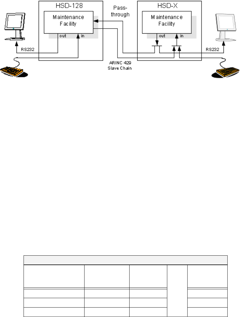
Page 4–4
18 September 2007
SYSTEM DESCRIPTION, INSTALLATION, AND MAINTENANCE MANUAL
eNfusion™ HSD-128 High-speed Data Terminal
Figure 4–1. Multi-Channel Maintenance Port Access
(2) Connection Requirements
This section describes specific cabling requirement needed to connect to and use the
HSD Maintenance Port Utility program.
(a) Cabling Notes
The HSD and HSD-X transceivers provide two options for physical connection
to the HSD maintenance port and utility program: direct connection and remote
connection.
Table 4–3, Table 4–4, Figure 4–2, and Figure 4–3 provide cabling details for the
HSD transceiver for both direct and remote connection types. Select one of the
connection options below to access the HSD maintenance utility program.
Table 4–5 and Figure 4–4 provide cabling details for the HSD-X transceiver for
both direct and remote connection types. Select one of the connection options
below to access the HSD maintenance utility program.
Note: The direct and remote connection points to the HSD maintenance port
cannot be used simultaneously.
Table 4–3. Remote Maintenance Port Access Cabling (HSD)
Remote Access
Pin Definition
ARINC
Connector
(Rear)
Remote
(DB9S)
Cable
(See Figure 4–2)
Computer
(DB9P)
Maint Port SGND (MP1J) 5 5
Maint Port Rx (MP1H) 3 3
Maint Port Tx (MP1G) 2 2

Page 4–5
18 September 2007
SYSTEM DESCRIPTION, INSTALLATION, AND MAINTENANCE MANUAL
eNfusion™ HSD-128 High-speed Data Terminal
(b) Maintenance Port Cable Assembly
HSD maintenance cable connections may vary in length, type of connection
used, and pinouts—depending on the access point used.
The cable assembly for HSD transceivers assumes that the computer’s COM
Port interface is a 9-Pin, D-Sub connector (DB9S). Cable assembly details for
HSD transceivers are presented in Figure 4–2 and Figure 4–3. The cable
assembly required for HSD-X transceivers is presented in Figure 4–4.
Note: The maximum cable length, shown in Figure 4–2 and Figure 4–3, assumes
that the length is measured from the ARINC 600 connector to the DB9
breakout connector.
Table 4–4. Front-Panel Maintenance Port Access Cabling (HSD)
Front Panel Access
Pin Definition Front Panel
DB25S
HSD
Maintenance
Cable
Connector
DB25P
Cable
(See Figure 4–3)
Computer
DB9P
Maint Port SGND 10 10 5
Maint Port Rx 12 12 3
112
Table 4–5. HSD-X Maintenance Port Pin Descriptions
Function Pin HDS-X
In/Out Signal Type
Data Loader in A 1 – Reserved
Data Loader in B 2 – Reserved
Spare 3 – –
Data Loader out A 4 – Reserved
Data Loader out B 5 – Reserved
Spare 6 – –
Data Loader Continuity Link (A) 7 – Reserved
Maint Port TD 8 Out RS-232
Maint Port GND 9 GND RS-232
Maint Port RD 10 In RS-232
Data Loader Continuity Link (B) 11 – Reserved
ATE Reserved 12 – ATE
ATE Reserved 13 GND ATE
ATE Reserved 14 – ATE
ATE Reserved 15 – ATE
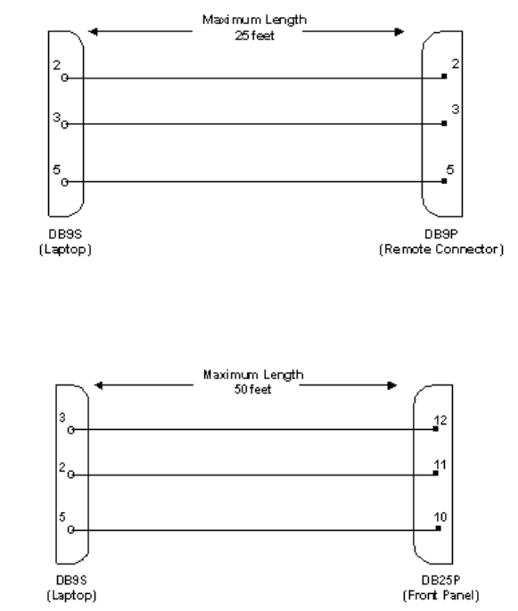
Page 4–6
18 September 2007
SYSTEM DESCRIPTION, INSTALLATION, AND MAINTENANCE MANUAL
eNfusion™ HSD-128 High-speed Data Terminal
Figure 4–2. Remote Access, Maintenance Cable (HSD)
Figure 4–3. Front Panel Access, Maintenance Cable (HSD)
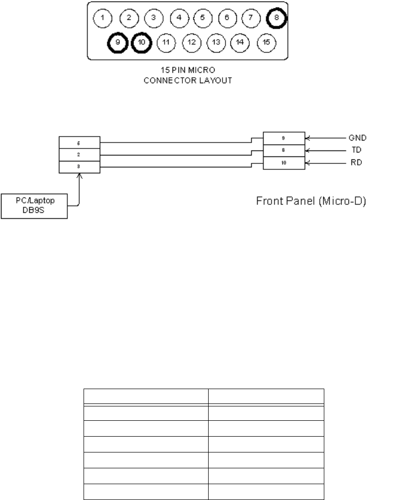
Page 4–7
18 September 2007
SYSTEM DESCRIPTION, INSTALLATION, AND MAINTENANCE MANUAL
eNfusion™ HSD-128 High-speed Data Terminal
Figure 4–4. HSD-X Front-Panel, Maintenance Port Cable
(c) Interface Requirements
A standard VT100 compatible terminal running an emulator program (such as
HyperTerminal, ProComm Plus, or another similar serial communication
package) provides the user interface to the HSD maintenance utility program.
The RS-232 connection settings for HSD and HSD-X maintenance ports are the
same. Refer to Table 4–6 for the recommended terminal connection settings.
(3) Accessing the Maintenance Utility Program
Access to the maintenance utility program menus is password protected. Each
password permits access to a different level of program functionality.
This document only describes the two password-protected access levels required to
perform operational testing and verification, software updates, and the basic system
monitoring and troubleshooting procedures provided in this manual: End User and
Field Representative.
Table 4–6. Terminal Connection Settings
Parameter Setting
Character Format ASCII
Baud Rate 19200 bps
No. of bits 8
Parity None
Stop bits 1
Flow Control None
Page 4–8
18 September 2007
SYSTEM DESCRIPTION, INSTALLATION, AND MAINTENANCE MANUAL
eNfusion™ HSD-128 High-speed Data Terminal
(a) End User Access: Level 1 – Password: MENU
This limited-access level is for anyone without technical training on the product.
It provides read-only access to help users diagnose problems with the assistance
of product support personnel.
(b) Field Representative Access: Level 2 – Password: MAINT
This level is for trained original equipment manufacturer (O.E.M.) installers and
product support personnel. This access level supports “read’” and limited “write”
capabilities. Users are able to disable/mask/clear faults, change satellite or LES
preferences, view and modify certain EEPROM parameters, and perform other
maintenance or upgrade functions.
(4) Using the HSD Maintenance Utility Program
This section describes the basic operating instructions for using and navigating the
HSD maintenance utility program.
(a) Entering Passwords
• For untrained users use Level 1 access: Type menu, and then press Enter.
• For trained technicians and product support personnel use Level 2 access:
Type maint, and then press Enter.
Note: The typed password does not appear on the screen.
(b) Navigating the HSD Maintenance Utility Program
• To scroll through the available menus press Ctrl+N.
• To go to the previous menu, press Ctrl+O.
• To refresh the menu screen or exit from a Reports Menu press ESC.
(c) Selecting MENU Items
• To enable test or data entry functions, press the letter associated with the
menu items. When a menu item is selected, the application may prompt the
user for additional inputs or selections.
(d) Selecting Report Items
• To open the list of possible system reports, press the equals sign (=).
A list of report items appears. Active reports show as toggled “ON.” Inactive
reports show as toggled “OFF.”
• To activate a report item, type the report item number and then
press Enter.
Note: Multiple report items can be activated at the same time; however, you must
type and enter each report item number separately.
•To turn “OFF” individual, active report items, type the report item number you
want to toggle off, and then press Enter.
•To turn “OFF” all active report items, press the equals sign (=) to display the
report item list, and then press X.

Page 4–9
18 September 2007
SYSTEM DESCRIPTION, INSTALLATION, AND MAINTENANCE MANUAL
eNfusion™ HSD-128 High-speed Data Terminal
(5) Menu Descriptions
This section describes the menus and menu items available in the HSD maintenance
utility program in Level 1 access (using the MENU password) and Level 2 access
(using the MAINT password) based on control processor software version 4.5 and
7.0. The differences between version 4.5 and 7.0 are noted within the examples. All
menus and items that appear in Level 1 also appear in Level 2.
No additional menus or menu items were added with the release of Version 7.5,
Control Processor software.
Note: Depending on the version of software and configuration mode installed, the
actual menus and screen displays in “live” systems may differ slightly from
the illustrations provided in this manual.
(a) Level 1 Menu Selections (Password: MENU)
Figure 4–5 shows all menus available to Level 1 users for control-processor
software version 4.5 to 7.0. Menu items added or changed in version 7.0, control
processor software are highlighted in bold text. No additional menus or menu
items were added with the release of Version 7.5, Control Processor software.
Figure 4–5. Level 1 MENU Selections
Note: Menu 3, item O ‘list ORT’ was added in control processor software version
7.0.
MENU1 FIRMWARE V7.0
Y explain hpa error status
<CTRL> N next menu <CTRL> O previous menu = select reports
MENU2 FIRMWARE V7.0
N annotate log file L re-enter logon password
V get firmware versions Z reset HSD-128
<CTRL> N next menu <CTRL> O previous menu = select reports
MENU 3 FIRMWARE V7.0
L list EEPROM S list event log
F list call log O list ORT
<CTRL> N next menu <CTRL> O previous menu = select reports
MENU 4 FIRMWARE V7.0
Q channel card forward ID's
<CTRL> N next menu <CTRL> O previous menu = select reports

Page 4–10
18 September 2007
SYSTEM DESCRIPTION, INSTALLATION, AND MAINTENANCE MANUAL
eNfusion™ HSD-128 High-speed Data Terminal
(b) Level 2 Menu Selections (Password: MAINT)
Figure 4–6 through Figure 4–12 show all menus and menu items available in
Level 2, menu options in control processor software, version 7.0. Menu items
added in version 7.0, control processor software are highlighted in bold. Where
applicable, any items that were deleted in version 7.0 are described and noted
below each menu. No additional menus or menu items were added with the
release of Version 7.5, Control Processor software.
Figure 4–6. Level 2: Menu 1
Figure 4–7. Level 2: Menu 2
Figure 4–8. Level 2: Menu 3
Note: In control processor software, version 7.0, menu 3, item N ‘serial number’
was removed.
MENU1 FIRMWARE V7.0
X override forward id L test LEDs
Y explain hpa error status S set hcm attenuator
R hcm RF threshold
<CTRL> N next menu <CTRL> O previous menu = select reports
MENU2 FIRMWARE V7.0
A set veh-relative azimuth E set veh-relative elevation
K desired az veh-rel velocity R resume automatic steering
T enter time of day N annotate log file
L re-enter logon password V get firmware versions
Z reset HSD-128 S set satellite longitude
<CTRL> N next menu <CTRL> O previous menu = select reports
MENU 3 FIRMWARE V7.0
L list EEPROM S list event log
M misc. EEPROM parameter F list call log
O list ORT P ocean region parameter
I set all LES id's
<CTRL> N next menu <CTRL> O previous menu = select reports

Page 4–11
18 September 2007
SYSTEM DESCRIPTION, INSTALLATION, AND MAINTENANCE MANUAL
eNfusion™ HSD-128 High-speed Data Terminal
Figure 4–9. Level 2: Menu10
Figure 4–10. Level 2: Menu 13
Figure 4–11. Level 2: Menu 14
MENU 4 FIRMWARE V7.0
Q channel card forward ID's F force spot beam selection
O set Ocean Region S change spot beam
J toggle ISDN connection M report MUX stats
<CTRL> N next menu <CTRL> O previous menu = select reports
Level 2: Menu 4
MENU10 FIRMWARE V7.0
L simul INS lat G simul INS long
H simul INS heading T simul INS true track
P simul INS pitch R simul INS roll
S simul INS speed A activate all simul words
X deactivate all simul words C simul port ACU status
B simul sb ACU status M activate antenna status words
N deactivate antenna status words
<CTRL> N next menu <CTRL> O previous menu = select reports
MENU 13 FIRMWARE V7.0
T query DATA IO elapsed time V query DATA IO version
S query DATA IO services C query DATA IO config pins
F DATA IO fault logging level X DATA IO console mode
<CTRL> N next menu <CTRL> O previous menu = select reports
MENU 14 FIRMWARE V7.0
N num entries in call table L list call table
T get call table
<CTRL> N next menu <CTRL> O previous menu = select reports

Page 4–12
18 September 2007
SYSTEM DESCRIPTION, INSTALLATION, AND MAINTENANCE MANUAL
eNfusion™ HSD-128 High-speed Data Terminal
Figure 4–12. Level 2, Menu 15
Figure 4–13. Level 2, Menu 18
Note: In control processor software, version 7.0, Menu 18 is available when the
terminal category is set to HSD-X Network, HSD-X Antenna, or Viper
configurations.
(6) Menu Item Descriptions
This section provides a brief description of the Level 2, maintenance-utility-program
menu items used for test and fault isolation procedures.
Although this section only provides illustrations and descriptions for Level 2 access,
descriptions of all Level 1 access menu items shown in Figure 4–5 are covered. (All
Level 1 menus are included in Level 2 Menus.)
In active HSD systems, menu screens display the firmware version.
Note: Depending on the version of software installed, the number of channels
cards in the system, and the HSD configuration mode, the menu and report
items available to users may differ slightly from the illustrations shown and
described in this document.
(a) Menu 1
Figure 4–14 shows the HSD maintenance utility program Menu 1 screen display.
Table 4–7 describes the items available in Menu 1.
In control processor software, version 7.0, the following changes were made to
menu 3 selections (delta between version 4.5 and 7.0). No additional menu items
were added with the release of Version 7.5, Control Processor software.
• Added menu items, S ‘set hcm attenuator’ and R ‘ hcm RF threshold’
MENU 15 FIRMWARE V7.0
V request channel card versions D channel card serial number
<CTRL> N next menu <CTRL> O previous menu = select reports
MENU 18 FIRMWARE V7.0
X HSD-X slave console mode B HSD-X slave cable loss
L list HSD-X slave cable loss V get HSD-X firmware version
<CTRL> N next menu <CTRL> O previous menu = select reports

Page 4–13
18 September 2007
SYSTEM DESCRIPTION, INSTALLATION, AND MAINTENANCE MANUAL
eNfusion™ HSD-128 High-speed Data Terminal
Figure 4–14. Menu 1 Screen Display
(b) Menu 2
Figure 4–15 shows the HSD maintenance utility program Menu 2 screen display.
Table 4–8 describes the items available in Menu 2.
In control-processor software version 7.0, no changes were made to menu 3
selections. No additional menu items were added with the release of Version 7.5,
Control Processor software.
MENU1 FIRMWARE V7.0
X override forward id L test LEDs
Y explain hpa error status S set hcm attenuator
R hcm RF threshold
<CTRL> N next menu <CTRL> O previous menu = select reports
Table 4–7. Menu 1 Item Descriptions
Menu Item Description
X: override forward id • Used in testing and fault isolation
• Enter a “test or alternate” Forward ID to use during fault
isolation procedures. Resetting the HSD or cycling the
power cancels this function.
L: test LEDs • Toggles the “Power ON” (LED 1) and ‘Fault’ (LED 2)
LEDs ON (A) and OFF (D) or returns them to software
control (X).
Y: explain hpa error
status
• Reports HPA status:
• Displays HPA OK when no error codes are
reported from the system’s power up test
• Displays HPA error code message if system’s
power up test fails
S• Used to set the preferred attenuation for Honeywell
Combined Mode (HCM) operation to reduce the output
signal level of the HCM module.
R• Displays the HCM module threshold parameters for the
RF:
• If the measured RF level is below this threshold,
the “RF low” bit is set in the HPA maintenance
word, which is then sent by the HSD control
processor to the Honeywell SDU.

Page 4–14
18 September 2007
SYSTEM DESCRIPTION, INSTALLATION, AND MAINTENANCE MANUAL
eNfusion™ HSD-128 High-speed Data Terminal
Figure 4–15. Menu 2 Screen Display
MENU2 FIRMWARE Vx.x
A set veh-relative azimuth E set veh-relative elevation
K desired az veh-rel velocity R resume automatic steering
T enter time of day N annotate log file
L re-enter logon password V get firmware versions
Z reset HSD-128 S set sat long
<CTRL> N next menu <CTRL> O previous menu = select reports
Table 4–8. Menu 2 Item Descriptions
Menu Items Item Description
Note: Menu 2 selections E and K are used to manually input navigational data to
point the antenna to a preferred satellite location and /or peak for a
maximum signal reception. These commands are typically used where no
IRS data is available.
A: set veh-relative
azimuth
• Antenna azimuth pointing offset with reference to the front
centerline of the aircraft
• Offset value entered in degrees from 0° to ± 180 °, where a
positive entry is clockwise (cw) and a negative entry is
counterclockwise (ccw)
K: desired az
veh-rel velocity
• Activates continuous antenna azimuth sweep at a set
elevation, as entered with menu item “E”
• Azimuth sweep velocity entered as deg/sec value
Note: When combined with a signal-monitoring “reports”
selection, sweep the antenna for maximum signal
strength to determine optimum location coordinates.
T: enter time of day • Permits the on-board entry of date and time for initial
one-time setting of the “Real Time Clock”
• Where no clock is available (on some early models) the time
may be set to time stamp a log file of a “reports” item
L: re-enter logon
password
• Permits a user to enter a new access level password:
menu or maint
Z: reset HSD • Enables a complete, soft reset of the LRU; once reset, the
menu access password must be re-entered
E: set veh-relative
elevation
• Antenna elevation pointing offset with respect to the aircraft
horizontal “rest” position, i.e., assumed to have no pitch or
roll offset
• Offset value entered in degrees from 0° to 90°
R: resume
automatic steering
• Re-activates programmed automatic antenna-steering in
both azimuth and elevation

Page 4–15
18 September 2007
SYSTEM DESCRIPTION, INSTALLATION, AND MAINTENANCE MANUAL
eNfusion™ HSD-128 High-speed Data Terminal
(c) Menu 3
In control processor software version 7.0, the following changes were made to
menu 3 selections (delta between version 4.5 and 7.0). No additional menu items
were added with the release of Version 7.5, Control Processor software.
• Deleted item N, ‘serial number’ as it was no longer required.
• The new item O, ‘list ORT’, displays all available ocean regions along with
the satellite longitude.
• The new item P, ‘ocean region parameter’, displays the ocean region number
along with the ocean region e.g. REGION 0: AOR WEST. This command
item configures both the Primary and Secondary LES access codes in the
unit.
• The new item I, ‘set all LES id’s’, sets the LES IDs in all the ocean regions
to the same LES access code and service provider.
• Removed several miscellaneous parameters from the Menu 3, item M
selections.
In menu 3, the following changes were made to item M ‘misc. EEPROM
parameter’:
• Removed extraneous parameters, 12, 19 to 24 and 28 to 31, which were
neither required for system configuration nor operation
• Added parameter 3, ‘GPS protection algorithm’ — used to disable the GPS
algorithms the HSD uses to prevent calls from interfering with the GPS
navigational system on the aircraft.
• Added parameter 4, ‘Registration Req’d before calls’ — used to require
successful ocean region registration before HSD calls are permitted (by
default ocean region registration is not required).
• Added parameter 17, ‘Viper Antenna Gain’ — used to configure the nominal
antenna gain used by the HSD when operating in Viper Mode—presuming
that the HSD is connected to an antenna that does not provide antenna status
words.
• Added parameter 18, ‘Viper HPA/ANT Loss’ — this is the RF loss between
the HPA and the antenna, when the system is operating in Viper Mode.
N: annotate log file • Allows for input of text into a log file
• This feature can be used to document information such as
test conditions, system or aircraft identification or any
pertinent information needed for later review
V: get firmware
versions
• Displays the system Kernel and Application software
versions as well as the channel card(s) and HPA firmware
revisions
S: set satellite
longitude
• Sets the satellite longitude
Table 4–8. Menu 2 Item Descriptions
Menu Items Item Description

Page 4–16
18 September 2007
SYSTEM DESCRIPTION, INSTALLATION, AND MAINTENANCE MANUAL
eNfusion™ HSD-128 High-speed Data Terminal
• Added parameter 45, ‘Category B Lower Frequency Limit’ and Parameter
46, “Category B Upper Frequency Limit” — these two parameters specify
the “CAT B” terminal frequency range. Calls, which involve transmitting
outside of this range, may interfere with the GPS navigational system if an
Aero H call occurs at the same time. Usually the GPS protection algorithm
tears down these calls.
Figure 4–16 shows the HSD maintenance utility program Menu 3 screen display
for version 7.0, control processor software. Table 4–9 describes the items
available in Menu 3.
Figure 4–16. Menu 3 Screen Display
MENU 3 FIRMWARE V7.0
L list EEPROM S list event log
M misc. EEPROM parameter F list call log
O list ORT P ocean region parameter
I set all LES id's
<CTRL> N next menu <CTRL> O previous menu = select reports
Table 4–9. Menu 3 Item Descriptions
Menu Item Item Description
L: list EEPROM • Displays a list of all system EEPROM parameters and their
corresponding values (this function is READ only)
• Certain parameters are set using menu 3, item M selection.
Figure 4–17 shows an example of the EEPROM listing
S: list event log • A list of system fault codes stored in non-volatile RAM
• When selected, several options are available:
0 = Most recent saved entry is displayed
S = Displays next most recent entry saved
• = Displays all remaining logged entries
1 = Special events (Does not include Ocean Region
Registration entries)
M: misc. EEPROM
parameter
• Enables entry or entry changes to some of the EEPROM
parameters listed in function ‘L’
Note: Parameters 5,6,7,8, 9, 13, 25, 26, 27, and 28 are
not accessible using Level 1 or Level 2 passwords
F: list call log • Displays call log files for HSD or HSD-X. When selected,
two options are available:
Press “F” to display complete list of all log files
Press “X” to list extended EIRP trace data

Page 4–17
18 September 2007
SYSTEM DESCRIPTION, INSTALLATION, AND MAINTENANCE MANUAL
eNfusion™ HSD-128 High-speed Data Terminal
O: list ORT • Displays all EEPROM parameters, including all cable
losses and LES configurations
P: ocean region
parameter
• Used to configure LES access codes (primary and
secondary service providers) for individual ocean regions
I: set all LES id’s • Used to configure the LES access codes to configure all
ocean regions to the same LES access code and service
provider (including primary and secondary service
providers)
Table 4–9. Menu 3 Item Descriptions
Menu Item Item Description

Page 4–18
18 September 2007
SYSTEM DESCRIPTION, INSTALLATION, AND MAINTENANCE MANUAL
eNfusion™ HSD-128 High-speed Data Terminal
Figure 4–17. Menu 3 – L: EEPROM Listing (Version 4.5)
EEPROM LISTING:
MAGIC NUMBER :OK
EEPROM VERSION NUMBER 2001
FIRMWARE VERSION 1018
SERIAL NUMBER: xxx
IGNORED FAULTS: 0
HARDWARE CONFIG: 0
NUMBER OF POWERUPS (index 0) 570
HOURS OF OPERATION (index 0) 117
MISCELLANEOUS PARAMETERS
HIT 'L' for MORE
HPA-ANTENNA CABLE LOSS: 2.5 dB
FORWARD ID: xxxxxx
AORW LES ACCESS CODE: 1
TERRESTRIAL NETWORK ID: 0
HPA-CHANNEL CARD CABLE LOSS: 10.0 dB
MAX HPA GAIN: 66.3 dB
MIN ANTENNA GAIN: 11.0 dB
MAX EIRP: 53.5 dB
MAX CHANNEL_CARD POWER: 0.0 dB
NUMBER OF CHANNEL CARDS : 2
FRONT PANEL LEDS ENABLED: 1
RX Attenuation (LAND-ON-WINGS): 0.0 dB
MIN SECS BETWEEN CHAN CARD RESETS: 300
HIT 'L' for MORE
MAINTENANCE PORT INVERSE VIDEO: 0
MAINTENANCE PORT DEGREES SYMBOL: 0
TERMINAL CATEGORY: HW STRAPPED VALUE
AOR W VALID BEAMS: 4 5 6
AOR E VALID BEAMS: 5 6
POR VALID BEAMS: 4 5 6
IOR VALID BEAMS 5 6
AORE LES ACCESS CODE: 1
POR LES ACCESS CODE: 1
IOR LES ACCESS CODE: 1
RECEIVER CALIBRATION (AREO): 11 dB
MAX HPA POWER: 18.0 dBw
HPA RESERVED POWER: 16.0 dBw
HIT ‘L’ for MORE
CHANNEL CARD STARTUP DELAY: 30 sec
RX32 ACTIVE: 1
DEFAULT LATITUDE: 45 DO’ 0.0”N
DEFAULT LONGITUDE: 75 DO’ 0.0”W
OBEY OXCO STATUS: YES
CCDEBUG PORT: NONE
COMBINED MODE BACKOFF ADJUSTMENT: 10.0 dB
CHECKSUM (stored at offset 462) 9656 OK
Longest write cycle took 0 MSEC

Page 4–19
18 September 2007
SYSTEM DESCRIPTION, INSTALLATION, AND MAINTENANCE MANUAL
eNfusion™ HSD-128 High-speed Data Terminal
Note: Depending on the version of software installed and the Terminal Category,
the EEPROM Listing shown may differ from those shown and described
here.
Figure 4–18. Menu 3 – Item M: Miscellaneous Parameters (Version 4.5)
Figure 4–19. Menu 3 – Item M: Miscellaneous Parameters (Version 7.0)
<CTRL> N next menu <CTRL> O previous menu = select reports
MISCELLANEOUS PARAMETERS
1 HPA-ANTENNA CABLE LOSS 18 AOR E VALID BEAMS
2 FORWARD ID 19 POR VALID BEAMS
3 AORW LES ACCESS CODE 20 IOR VALID BEAMS
4 TERRESTRIAL NETWORK ID 21 AORE LES ACCESS CODE
10 NUMBER OF CHANNEL CARDS 22 POR LES ACCESS CODE
11 FRONT PANEL LEDS ENABLED 23 IOR LES ACCESS CODE
12 RX ATTENUATION (LAND-ON-WINGS) 24 RECEIVER CALIBRATION (AERO)
14 MAINTENANCE PORT INVERSE VIDEO 28 RX32 ACTIVE
15 MAINTENANCE PORT DEGREES SYMBOL 29 DEFAULT LATITUDE
16 TERMINAL CATEGORY 30 DEFAULT LONGITUDE
17 AOR W VALID BEAMS 31 OBEY OXCO STATUS
WHICH PARAMETER # ?
MISCELLANEOUS PARAMETERS
1 HPA-TO-ANTENNA TOTAL LOSS 11 FRONT PANEL LEDS ENABLED
2 FORWARD ID 14 MAINTENANCE PORT INVERSE VIDEO
3 GPS PROTECTION ALGORITHMS 15 MAINTENANCE PORT DEGREES SYMBOL
4 REGISTRATION REQ'D BEFORE CALLS 16 TERMINAL CATEGORY
10 NUMBER OF CHANNEL CARDS 17 VIPER ANTENNA GAIN
WHICH PARAMETER # <CTRL> N for next page ?
18 VIPER HPA/ANT LOSS 31 OBEY OXCO STATUS
24 RECEIVER CALIBRATION 42 HCM AERO/M4 PRIORITIZATION
28 RX32 ACTIVE 45 CATEGORY B LOWER FREQUENCY LIMIT
29 DEFAULT LATITUDE 46 CATEGORY B UPPER FREQUENCY LIMIT
30 DEFAULT LONGITUDE

Page 4–20
18 September 2007
SYSTEM DESCRIPTION, INSTALLATION, AND MAINTENANCE MANUAL
eNfusion™ HSD-128 High-speed Data Terminal
Table 4–10. Menu 3, Item 'M' EEPROM Parameter Descriptions (Version 4.5)
Parameter
#Parameter Title Description
1 HPA Cable loss • Measured transmit coax cable loss from the HSD
at MPC1 to the antenna including the DLNA loss
(0.8 dB)
• Maximum is 2.5 dB – 0.8 dB = 1.7 dB
2 Forward ID • Entry required ONLY if the ID is not strapped,
refer to "Installation" on page 3-1 for strapping
details
3, 21, 22,
and 23
AORW, AORE, POR,
and IOR ‘LES’
Access Codes
• Inmarsat Service Provider LES access code
entry; default is “1”
4 Terrestrial Network ID • Used to change Terrestrial Network ID (where
applicable)
10 Number of Channel
Cards
• Entry selects the number of channel cards the
system is configured for.
• Default for Stand-Alone Mode installations is “2”
11 Front Panel LEDs
Enabled
• Future consideration is provided for additional
LEDs, beyond the two currently activated
• Default is “2”’
14 Maintenance Port
Inverse Video
• Enables a selected “reports” item to be
highlighted in Inverse Video when it is activated
• Default is “1” (activated)
15 Maintenance Port
Degrees Symbol
• Offers a choice of displaying the letter “D” or the
degree symbol “°” when viewing the lat/long
information displayed in the ‘Reports’ output:
• Select “0” to use the letter “D”, e.g. 180.0 D
• Select “1” to use a degree symbol “°”, e.g.
180.0°

Page 4–21
18 September 2007
SYSTEM DESCRIPTION, INSTALLATION, AND MAINTENANCE MANUAL
eNfusion™ HSD-128 High-speed Data Terminal
16 Channel Card
Category
• Offers an LRU configuration choice of:
• 0 for SAT-906
• 1 for Stand-Alone
• 2 for HW Strapping
• 3 for MCS3000
• 4 for MCS6000
• 5 for MCS7000
• 6 for MCS Combined
• 7 for Stand-Alone without antenna
• 8 for Honeywell Collaborative
• 9 for Cooperative Rockwell Collins
SAT-906
• Default is “2” (where hardware is read on
power-up)
17, 18, 19,
and 20
AORW, AORE, POR,
and IOR Valid Beams
• Not applicable (applied to prototype channel card
software)
24 Receiver Calibration
(AERO)
• Enables attenuation of receive RF input level to
the channel cards
• Entered as an absolute number, e.g., 10, means
10 dB of input RF attenuation is added
•Not applicable to HSD systems with version
C30 (or later) channel card software (Version
C30 and later channel card software
automatically adjusts RF input)
• Default is “0”
28 RX32 Active • Not applicable (applied to prototype HPA
systems)
29 Default Latitude • Allows user to enter a default latitude value
• Reset the HSD to activate revised default values
30 Default Longitude • Allows user to enter a default longitude value
• Reset the HSD to activate revised default values
31 Obey OXCO Status • Prevents system operation until OCXO is
warmed up (unless overridden)
• Use parameter setting to override warm-up
during testing procedures
Table 4–10. Menu 3, Item 'M' EEPROM Parameter Descriptions (Version 4.5)
Parameter
#Parameter Title Description

Page 4–22
18 September 2007
SYSTEM DESCRIPTION, INSTALLATION, AND MAINTENANCE MANUAL
eNfusion™ HSD-128 High-speed Data Terminal
Table 4–11. Menu 3, Item 'M' EEPROM Parameter Descriptions (Version 7.0)
Parameter
#Parameter Title Description
1HPA cable loss • Measured transmit coax cable loss from the
HSD at MPC1 to the antenna including the
DLNA loss—maximum is 2.5 dB
2Forward ID • Entry required ONLY if the ID is not strapped,
refer to "Installation" on page 3-1 for strapping
details
3GPS protection
algorithms
• Used to disable the GPS algorithms the HSD
uses to prevent calls from interfering with the
GPS navigational system on the aircraft.
4Registration req’d
before calls
• Used to change Terrestrial Network ID (where
applicable)
10 Number of channel
cards
• Entry selects the number of channel cards the
system is configured for—default for
Stand-Alone Mode installations is “2”
11 Front panel LEDs
enabled
• Future consideration is provided for
additional LEDs, beyond the two currently
activated—default is “2”’
14 Maintenance port
inverse video
• Enables a selected “reports” item to be
highlighted in Inverse Video when it is
activated—default is “1” (activated)
15 Maintenance port
degrees symbol
• Offers a choice of displaying the letter “D” or
the degree symbol “°” when viewing the
lat/long information displayed in the ‘Reports’
output:
• Select “0” to use the letter “D”, e.g.
180.0 D
• Select “1” to use a degree symbol “°”,
e.g. 180.0°

Page 4–23
18 September 2007
SYSTEM DESCRIPTION, INSTALLATION, AND MAINTENANCE MANUAL
eNfusion™ HSD-128 High-speed Data Terminal
16 Channel card
category
• Offers an LRU configuration choice of:
•0 for SAT-906
• 1 for Stand-Alone
• 2 for HW Strapping
•3 for MCS3000
•4 for MCS6000
•5 for MCS7000
• 6 for MCS Combined
• 7 for Stand-Alone without antenna
• 8 for HCM Combined (Honeywell
Combined Mode)
• 9 for Cooperative Rockwell Collins
SAT-906
• 10 not used
• 11 for HSD-X Network (Multi-Channel
AERO)
• 12 for HSD-X Network without antenna
(Multi-Channel Non AERO)
• 13 for VIPER
• Default is “2” (where hardware is read on
power-up)
17 Viper antenna gain • Used to configure the nominal antenna gain
used by the HSD when operating in Viper
Mode—presuming that the HSD is connected
to an antenna that does not provide antenna
status words
18 Viper HPA/ANT loss • Used to configure the nominal antenna gain
used by the HSD when operating in Viper
Mode—presuming that the HSD is connected
to an antenna that does not provide antenna
status words
Table 4–11. Menu 3, Item 'M' EEPROM Parameter Descriptions (Version 7.0)
Parameter
#Parameter Title Description

Page 4–24
18 September 2007
SYSTEM DESCRIPTION, INSTALLATION, AND MAINTENANCE MANUAL
eNfusion™ HSD-128 High-speed Data Terminal
24 Receiver Calibration
(AERO)
• Enables attenuation of receive RF input level
to the channel cards
• Entered as an absolute number, e.g., 10,
means 10 dB of input RF attenuation is added
•Not applicable to HSD systems with
version C30 (or later) channel card
software (Version C30 and later channel
card software automatically adjusts RF input)
• Default is “0”
28 RX32 Active • Not applicable (applied to prototype HPA
systems)
29 Default Latitude • Allows user to enter a default latitude value
• Reset the HSD to activate revised default
values
30 Default Longitude • Allows user to enter a default longitude value
• Reset the HSD to activate revised default
values
31 Obey OXCO status • Prevents system operation until OCXO is
warmed up (unless overridden)
• Use parameter setting to override warm-up
during testing procedures
42 HCM AERO/M4
prioritization
• Sets HPA power allocation to Aero H/H+ or
Swift64 call priority (1=M4, 0=AERO-H)
• Default set to AERO priority
45 Category B lower
frequency limit
• Used to specify category B terminal lower
frequency range. Calls transmitting outside of
this specified range may interfere with the
GPS navigational system if an Aero H call
occurs simultaneously; however, in this
event, the GPS protection algorithm usually
tears down the call
46 Category B upper
frequency limit
• Used to specify category B terminal upper
frequency range. Calls transmitting outside of
this specified range may interfere with the
GPS navigational system if an Aero H call
occurs simultaneously; however, in this
event, the GPS protection algorithm usually
tears down the call
Table 4–11. Menu 3, Item 'M' EEPROM Parameter Descriptions (Version 7.0)
Parameter
#Parameter Title Description

Page 4–25
18 September 2007
SYSTEM DESCRIPTION, INSTALLATION, AND MAINTENANCE MANUAL
eNfusion™ HSD-128 High-speed Data Terminal
(d) Menu 4
In control-processor software version 7.0, the following changes were made to
Menu 4 selections (delta between version 4.5 and 7.0). No additional menu items
were added with the release of Version 7.5, Control Processor software.
• Removed Menu 4, item F, ‘force spot beam’ selection.
Figure 4–20 shows the HSD maintenance utility program Menu 4 screen display.
Table 4–12 describes the items available in Menu 4.
Figure 4–20. Menu 4 Screen Display
MENU 4 FIRMWARE V7.0
Q channel card forward ID's O set Ocean Region
S change spot beam J toggle ISDN connection
M report MUX stats
<CTRL> N next menu <CTRL> O previous menu = select reports
Table 4–12. Menu 4 Item Descriptions
Menu Item Item Description
Q: channel card
forward IDs
• Enables viewing of channel cards, # 1 and # 2 Forward IDs
O: set Ocean Region • Allows for manual selection of satellite Ocean Regions:
AORW: “0”
AORE: “1”
POR: “2”
IOR: “3”
• To revert to programmed selection, type –1 and press Enter
for AUTO selection
J: toggle ISDN
connection
• Used for testing and fault isolation purposes
• Connects ISDN 1 lines to Channel Card 2 (Does not work
in reverse—ISDN 2 to ISDN 1)
• Redirection only applies until the system is reset
S: change spot beam • Enables manual selection of specific spot beams
independently assigned for each channel card
M: report MUX stats • Not applicable
• Used for engineering debugging purposes only

Page 4–26
18 September 2007
SYSTEM DESCRIPTION, INSTALLATION, AND MAINTENANCE MANUAL
eNfusion™ HSD-128 High-speed Data Terminal
(e) Menu 10
Menu 10 items are used to manually enter INS parameters to simulate the INS
data required for HSD operation when INS data is unavailable. Figure 4–21
shows the HSD maintenance utility program Menu 10 screen display. Table 4–
13 describes the items available in Menu 10. No additional menu items were
added with the release of Version 7.5, Control Processor software.
In control-processor software version 7.0, the following changes were made to
Menu 10 selections (delta between version 4.5 and 7.0).
• Added item C, ‘simul port ACU status’, which prompts the user to enter both
the port antenna gain in dB and the message rate in Hz.
• Added item M, ‘activate antenna status words’, which activates all set
antenna status words.
• Added item N, ‘deactivate antenna status words’, which deactivates all set
antenna status words.
• Added item B, ‘simul sb ACU status’, which prompts the user to enter the
Starboard antenna gain in dB and the message rate in Hz.
Figure 4–21. Menu 10 Screen Display
MENU10 FIRMWARE Vx.x
L simul INS lat G simul INS long
H simul INS heading T simul INS true track
P simul INS pitch R simul INS roll
S simul INS speed A activate all simul words
X deactivate all simul words C simul port ACU status
B simul sb ACU status M activate antenna status words
N deactivate antenna status words
<CTRL> N next menu <CTRL> O previous menu = select reports
Table 4–13. Menu 10 Item Descriptions
Menu Item Item Description
L: simul INS lat • Allows user to simulate a latitude by overriding the data
received from the aircraft INS
H: simul INS heading • Allows user to simulate a aircraft heading by overriding
the data received from the aircraft INS
P: simul INS pitch • Allows user to simulate aircraft pitch by overriding the
data received from the aircraft INS
S: simul INS speed • Allows user to simulate aircraft speed by overriding the
data received from the aircraft INS
X: deactivate all simul
words
• De-activates all simulated parameters reverting the HSD
system back to using the INS data received from the
aircraft

Page 4–27
18 September 2007
SYSTEM DESCRIPTION, INSTALLATION, AND MAINTENANCE MANUAL
eNfusion™ HSD-128 High-speed Data Terminal
(f) Menu 13
Menu 13 items are used to query and debug systems with Data I/O Card 2
(available on HSD models 1110-A-0150 and 1110-A-0160 or other HSD models
via service bulletin 1110-SB-0004). Menu 13 is the same in all control processor
software versions 4.5 and later.
Figure 4–22 shows the HSD maintenance utility program Menu 13 screen
display. Table 4–14 describes the items available in Menu 13.
Figure 4–22. Menu 13 Screen Display
B: simul sb ACU
status
• Used to enter the starboard antenna gain in dB and the
message rate in Hz
N: deactivate antenna
status words
• Used to deactivate all set antenna status words
G: simul INS long • Allows user to simulate aircraft longitude by overriding
the data received from the aircraft INS
T: simul ins true track • Allows user to simulate true track by overriding the data
received from the aircraft INS
R: simul INS roll • Allows user to simulate aircraft roll by overriding the data
received from the aircraft INS
A: activate all simul
words
• Activates all input simulate parameters overriding the INS
data received from the aircraft
• Lat and Long values from the EEPROM values set in
Menu 3
C: simul port ACU
status
• Used to enter both the port antenna gain in dB and the
message rate in Hz
M: activate antenna
status words
• Used to activate all set antenna status words
MENU 13 FIRMWARE Vx.x
T query DATA IO elapsed time V query DATA IO version
S query DATA IO services C query DATA IO config pins
F DATA IO fault logging level X DATA IO console mode
<CTRL> N next menu <CTRL> O previous menu = select reports
Table 4–13. Menu 10 Item Descriptions
Menu Item Item Description

Page 4–28
18 September 2007
SYSTEM DESCRIPTION, INSTALLATION, AND MAINTENANCE MANUAL
eNfusion™ HSD-128 High-speed Data Terminal
(g) Menu 14
Menu 14 items are used for debugging and clarifying call routing issues. Menu
14 is the same in all control processor software versions 4.5 and later.
Figure 4–23 shows the HSD maintenance utility program Menu 14 screen
display. Table 4–15 describes the items available in Menu 14.
Figure 4–23. Menu 14 Screen Display
Table 4–14. Menu 13 Item Descriptions
Menu Item Item Description
T: query Data IO elapsed
time
• Displays the time (in seconds) since the last Data I/O
reset
S: query Data IO services • Displays active interfaces
F: Data IO fault logging
level
• Sets the level of minimum severity of events that are
reported to the Data I/O card
V: query Data IO version • Displays the firmware version of the Data I/O card
C: query Data I/O config
pins
• Displays the Data I/O configuration pin summary
X: Data IO console mode • Opens a virtual TTY session to the Data I/O
maintenance port on the HSD
MENU 14 FIRMWARE Vx.x
N num entries in call table L list call table
T get call table
<CTRL> N next menu <CTRL> O previous menu = select reports
Table 4–15. Menu 14 Item Descriptions
Menu Item Item Description
N: num entries in call
table
• Displays the call table number entries for
fixed-originated or mobile-originated calls for either
channel card 1 or channel card 2
T: get call table • Displays the call table lists for fixed-originated or
mobile-originated calls for either channel card 1 or
channel card 2
L: list call table • Lists the call table for fixed-originated or
mobile-originated calls for either channel card 1 or
channel card 2
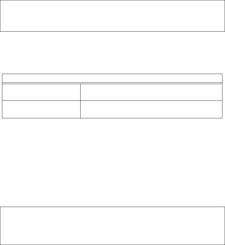
Page 4–29
18 September 2007
SYSTEM DESCRIPTION, INSTALLATION, AND MAINTENANCE MANUAL
eNfusion™ HSD-128 High-speed Data Terminal
(h) Menu 15
Menu 15 was added in control processor software version 7.0 to allow the user
to query the system for channel-card, software versions and serial number
information.
Figure 4–24 shows the HSD maintenance utility program Menu 15 screen
display. Table 4–16 describes the items available in Menu 15.
Figure 4–24. Menu 15 Screen Display
(i) Menu 18
Menu 18 was added in control processor software version 7.0 to support
Multi-Channel configurations. No additional menu items were added with the
release of Version 7.5, Control Processor software. Menu 18 is only available if
the HSD system is configured to either HSD-X Network, HSD-X without Antenna,
or Viper terminal categories.
Figure 4–25 shows the HSD maintenance utility program Menu 18 screen
display. Table 4–17 describes the items available in Menu 18.
Figure 4–25. Menu 18 Screen Display
MENU 15 FIRMWARE V7.0
V request channel card versions D channel card serial number
<CTRL> N next menu <CTRL> O previous menu = select reports
Table 4–16. Menu 15 Item Descriptions
Menu Item Item Description
V: request channel card
versions
• Displays software versions for a selected channel
card
D: channel card serial
number
• Displays the serial number of the selected channel
card
MENU 18 FIRMWARE V7.0
X HSD-X slave console mode B HSD-X slave cable loss
L list HSD-X slave cable loss V get HSD-X firmware version
<CTRL> N next menu <CTRL> O previous menu = select reports

Page 4–30
18 September 2007
SYSTEM DESCRIPTION, INSTALLATION, AND MAINTENANCE MANUAL
eNfusion™ HSD-128 High-speed Data Terminal
(7) Report Item Descriptions
When testing or troubleshooting the HSD system, monitoring real-time system data
is sometimes required. Figure 4–26 shows all the report items potentially available to
Level 2 user.
Most reports are used for factory debugging purposes only. This document describes
only the reports typically used in the field for operational and fault isolation testing.
Note: Depending on the version of software installed, the maintenance utility
program report items displayed may differ from those shown in Figure 4–
26 and Figure 4–27.
Table 4–17. Menu 15 Item Descriptions
Menu Item Item Description
X: HSD-X slave console
mode
• Activates a system control connection to a selected
HSD-X unit installed on the system
L: list HSD-X slave cable
loss
• Select this item to display the HSD to HSD-X cable
loss for a selected HSD-X unit installed on the system
B: HSD-X slave cable loss • Used to enter the measured HSD to HSD-X cable
loss for selected HSD-X unit
V: get HSD-X firmware
version
• Select this item to display the software version of a
selected HSD-X unit installed on the system

Page 4–31
18 September 2007
SYSTEM DESCRIPTION, INSTALLATION, AND MAINTENANCE MANUAL
eNfusion™ HSD-128 High-speed Data Terminal
Figure 4–26. HSD Maintenance Utility Program: Report Items (Version 4.5)
1 OFF messages to channel card #1 13 OFF messages to channel card #2
2 OFF hex output to channel card #1 14 OFF hex output to channel card #2
3 OFF responses from channel card #1 15 OFF responses from channel card #2
4 OFF hex input from channel card #1 16 OFF hex input from channel card #2
5 OFF channel #1 misc info 17 OFF channel #2 misc info
6 OFF sb antenna arinc input 18 OFF port antenna arinc input
7 OFF sb antenna maintenance word 19 OFF port antenna maintenance word
8 OFF sb antenna status word 20 OFF port antenna status word
9 OFF channel card call status 21 OFF call codes
10 OFF channel card THA codes 22 OFF spot beam selection
11 OFF channel card errors 23 OFF standard output
12 OFF INS input 24 OFF doppler, antenna az/el
25 OFF HPA arinc i/o 37 OFF combined-mode spoofed output
26 OFF HPA error status 38 OFF combined-mode power allotment
27 OFF HPA/channel card backoffs 39 OFF combined-mode debugging
28 OFF miscellaneous digital inputs 40 OFF enthusiastic combined-mode
debug
29 OFF channel card A_AM msgs 41 OFF delta combined-mode debugging
30 OFF multi-control arinc bus 42 OFF raw arinc data from ITS
31 OFF ocean region info 43 OFF high-precision hpa power
32 OFF hex input from data i/o 44 OFF hpa calibration (gain droop)
33 OFF hex output to data i/o 45 OFF combined mode ocean region debug
34 OFF input from data i/o 46 OFF hpa resets
35 OFF changes in multi-control bus 47 OFF channel card temperature
36 OFF unit test call setup 48 OFF hexadecimal INS input
49 OFF main loop latency 59 OFF RC Satellite Position
50 OFF main loop timing 60 OFF debug channel card power
51 OFF one second tick 61 OFF non-zero channel card power
52 OFF extended call codes 62 OFF m4 availability status
53 OFF standalone w/o ant data 63 OFF enthusiastic output to RC SDU
54 OFF RC SDU time and date 64 OFF channel card frequencies
55 OFF RC arinc i/o (hex) 65 OFF enthusiastic messages from HPA
56 OFF RC misc arinc i/o (ascii) 66 OFF channel card boot sequence
57 OFF RC EIRP 67 OFF HPV power meter/attenuator
58 OFF RC SAT-906 Status

Page 4–32
18 September 2007
SYSTEM DESCRIPTION, INSTALLATION, AND MAINTENANCE MANUAL
eNfusion™ HSD-128 High-speed Data Terminal
Figure 4–27. HSD Maintenance Utility Program: Report Items (Version 7.0)
1 OFF messages to channel card #1 13 OFF messages to channel card #2
2 OFF hex output to channel card #1 14 OFF hex output to channel card #2
3 OFF responses from channel card #1 15 OFF responses from channel card #2
4 OFF hex input from channel card #1 16 OFF hex input from channel card #2
5 OFF channel #1 misc info 17 OFF channel #2 misc info
6 OFF sb antenna arinc input 18 OFF port antenna arinc input
7 OFF sb antenna maintenance word 19 OFF port antenna maintenance word
8 OFF sb antenna status word 20 OFF port antenna status word
9 OFF channel card call status 21 ON call codes
10 OFF channel card THA codes 22 OFF spot beam selection
11 OFF channel card errors 23 OFF standard output
12 OFF INS input 24 OFF doppler, antenna az/el
25 OFF HPA arinc i/o 37 OFF combined-mode spoofed output
26 OFF HPA error status 38 OFF combined-mode power allotment
27 OFF HPA/channel card backoffs 39 OFF combined-mode debugging
28 OFF miscellaneous digital inputs 40 OFF enthusiastic combined-mode
debug
29 OFF channel card A_AM msgs 41 OFF delta combined-mode debugging
30 OFF multi-control arinc bus 42 OFF raw arinc data from ITS
31 OFF ocean region info 43 OFF high-precision hpa power
32 OFF hex input from data i/o 44 OFF hpa calibration (gain droop)
33 OFF hex output to data i/o 45 OFF combined mode ocean region debug
34 OFF input from data i/o 46 OFF hpa resets
35 OFF changes in multi-control bus 47 OFF channel card temperature
36 OFF unit test call setup 48 OFF hexadecimal INS input
49 OFF main loop latency 61 OFF non-zero channel card power
50 OFF main loop timing 62 OFF m4 availability status
51 OFF one second tick 63 OFF enthusiastic output to RC SDU
52 OFF extended call codes 64 OFF channel card frequencies
53 OFF standalone w/o ant data 65 OFF enthusiastic messages from HPA
54 OFF RC SDU time and date 66 OFF channel card boot sequence
55 OFF RC arinc i/o (hex) 67 OFF debug honeywell combined mode
56 OFF RC misc arinc i/o (ascii) 68 OFF CFDS debugging
57 OFF RC EIRP 69 OFF vt100 scenario
58 OFF RC SAT-906 Status 70 OFF HCM input
59 OFF RC Satellite Position 71 OFF HCM power level
60 OFF debug channel card power 72 OFF DATA I/O events
73 OFF HCM power control 85 OFF debug CC#2 channel card power
74 OFF TIM HCM power debugging 86 OFF Channel card rx attenuation
75 OFF HCM BITE 87 OFF interworking report
76 OFF HSD-X arinc messages 88 OFF all words to SDU
77 OFF HSD-X net configuration 89 OFF debug call teardown
78 OFF vt100 eirp/power 90 OFF debug cc backoff
79 OFF dialtone debugging 91 OFF HSD frequencies
80 OFF RC CC#2 SDU time and date 92 OFF intermod debugging
81 OFF RC CC#2 arinc i/o (hex) 93 OFF spot beam debugging
82 OFF RC CC#2 misc arinc i/o (ascii) 94 OFF vt100 channel card info
83 OFF RC CC#2 EIRP 95 OFF vt100 debugging
84 OFF RC CC#2 SAT-906 Status

Page 4–33
18 September 2007
SYSTEM DESCRIPTION, INSTALLATION, AND MAINTENANCE MANUAL
eNfusion™ HSD-128 High-speed Data Terminal
(8) Activating Maintenance Reports
In Level 1, menu access, report item 23 (standard output) is automatically generated
when the equals sign (=) is pressed. Once activated, the report data output is repeated
on the computer display at one-second intervals.
Level 2, maint access provides more flexibility in the use of the reports function. This
access level permits the activation or de-activation any one of the report items (toggle
ON and OFF).
(a) Report Items: General Guidelines
1. Press the equal sign on the keyboard (=) to open the Report Item menu.
2. To activate a report, type the number of the report item needed, and then
press Enter. This toggles ON the report number entered. To toggle the report
OFF, type in the report number again, and press Enter.
3. Press X to disable all report items (toggles reports OFF).
4. Press Ctrl+N to display the next group of report items.
5. Press S to save all selected report items to EEPROM. If the items selected
are not saved, they are "de-activated" when the system is reset or power is
cycled to the unit.
6. Press Esc (in Level 2 access only) to start the scrolling report display. Press
Esc again to return to the MENU selection screen.
(b) Report Items: Descriptions
Not all the report items are used in the testing or troubleshooting of the system.
This section describes only the more commonly used report items.
1. Report Item: 23
Use report item #23 (the most comprehensive report) to get an overall general
impression of the HSD system health. An example of the contents of report
item 23 is shown in Figure 4–28. Table 4–18 provides a brief description of
the parameters. Each distinct parameter is numbered for description
purposes.
Figure 4–28. Example of Report Item 23
145D38'52.9"N 74D59'29.3"W 2PT 0.2D 3RL -0.4D 4HD 349.9D 5TK 0.2D 60
knots
710:26:07 8dop 0 ppb 9az 161.6 deg 10el 33.6 deg 11AOR WEST 12ant gain
13 (sbd)
13CARD #1: 14C/No=51.5 dB/Hz 15sig=-16.8 1627 C 17no call 18beam=4
13CARD #2: 14C/No=51.5 dB/Hz 15sig=-15.4 1627 C 17no call 18beam=4

Page 4–34
18 September 2007
SYSTEM DESCRIPTION, INSTALLATION, AND MAINTENANCE MANUAL
eNfusion™ HSD-128 High-speed Data Terminal
Note: When the aircraft is stationary the field may appear as ¾’s.
2. Report Items: 5 & 17, 8 & 20, and 21
Some other commonly used report items, used in the testing or
troubleshooting of the system, are shown in Figure 4–29. These report items
shown are only available to Level 2, maint access users.
Note: Depending on the version of software installed, and the user’s
selection of reports, the maintenance utility program report items
displayed may differ from those shown in the example
illustrated Figure 4–29.
Note: Signal strength values (C/no=) in early versions of software do not
show the decimal point. If operating HSD transceivers with earlier
software, divide the C/no value by ten.
Table 4–18. Report 23 Item Descriptions
Report 23
Item Number Description
1 IRS lat/long as interpreted by the HSD
2 Aircraft pitch angle, where “UP” is +ve
3 Aircraft roll angle, where clockwise (cw) is +ve
4 Aircraft heading; where the nose of the aircraft is pointing, based on yaw
offset
5 Aircraft true track; direction the aircraft is flying—not necessarily the
direction it is pointing (See NOTE)
6 Aircraft velocity
7 Time, based on the system real time clock
8 Doppler frequency offset; increases with velocity (See NOTE)
9 Antenna azimuth pointing to the satellite, with respect to the nose of the
aircraft
10 Antenna elevation angle to the satellite, with respect to the horizontal
position of the aircraft
11 Ocean Region the system is logged-on to
12 Reported antenna gain and the selected antenna, port or starboard
13 Indicates the channel card for which results 14) to 17) relate to
14 RF input Carrier-to-Noise (C/No) level; typically 50.0 to 55.0
15 RF input signal level; typically –12.0 to –18.0 when not ”in call”: *not to
exceed 0 when “in-call”
16 HSD internal LRU temperature
17 System call status
18 Satellite beam the card is registered on

Page 4–35
18 September 2007
SYSTEM DESCRIPTION, INSTALLATION, AND MAINTENANCE MANUAL
eNfusion™ HSD-128 High-speed Data Terminal
Figure 4–29. Maintenance Port, Report Items
Report 5; Channel card #1 & #2 miscellaneous information:
CARD #1: C/No=51.8 sig=-16.6 no call beam=4 AOR WEST bt=OK oc=OK int=8080
CARD #1: C/No=51.6 sig=-16.8 no call beam=4 AOR WEST bt=OK oc=OK int=8080
CARD #2: C/No=52.0 sig=-16.1 no call beam=4 AOR WEST bt=OK oc=OK int=8080
CARD #2: C/No=51.7 sig=-16.3 no call beam=4 AOR WEST bt=OK oc=OK int=8080
Report 8 & 20; Starboard and Port Antenna Status:
starboard status: 0x608236 SDI: STARBOARD SSM: NORMAL OPERATION gain: 13
OMNIDIRECTIONAL MODE open loop tracking starboard active HGA LNA on
starboard status: 0x608236 SDI: STARBOARD SSM: NORMAL OPERATION gain: 13
OMNIDIRECTIONAL MODE open loop tracking starboard active HGA LNA on
starboard status: 0x608236 SDI: STARBOARD SSM: NORMAL OPERATION gain: 13
port status: 0x600201 SDI: PORT/TOP SSM: NORMAL OPERATION gain: 0
OMNIDIRECTIONAL MODE open loop tracking starboard active HGA LNA off
port status: 0x600201 SDI: PORT/TOP SSM: NORMAL OPERATION gain: 0
OMNIDIRECTIONAL MODE open loop tracking starboard active HGA LNA off
Report 21; Call Codes:
13:39:00 #1 ABC123 E4 start 800124 21.50 dBW mobile aero 64k speech 28 C
54 dB/Hz
13:39:00 #2 ABC456 E4 start 800622 19.50 dBW mobile aero 64k UDI 30 C 0 dB/Hz
13:39:06 #1 ABC123 E4 start 800124 21.50 dBW mobile aero 64k speech 28 C
0 dB/Hz
13:39:06 #2 ABC456 E4 start 800622 19.50 dBW mobile aero 64k UDI 30 C 0 dB/Hz
13:39:12 #1 ABC123 E4 start 800124 21.50 dBW mobile aero 64k speech 28 C
55 dB/Hz
13:39:12 #2 ABC456 E4 start 800622 19.50 dBW mobile aero 64k UDI 30 C 0 dB/Hz
13:39:18 #1 ABC123 E4 start 800124 21.50 dBW mobile aero 64k speech 28 C
0 dB/Hz
13:39:19 #2 ABC456 E4 stop 1001 call cleared by MES terminal 30 C 0 dB/Hz
13:39:20 #1 ABC123 E4 stop 1001 call cleared by MES terminal 28 C 0 dB/Hz
13:39:19 #2 ABC456 E4 stop 1001 call cleared by MES terminal 30 C 0 dB/Hz
13:39:20 #1 ABC123 E4 stop 1001 call cleared by MES terminal 28 C 0 dB/Hz
Table 4–19. Report information
Report(s) Information
Report 5 & 17 Channel card #1 & #2 miscellaneous information:
(C/No) - RF input carrier to noise level (value displayed is typically 50 to 55
when not “in-call” and 55 to 65 when “in-call”-may also show as “0’s”)
(sig) - RF input signal level (typically –12 to –18 when not “in-call”)
(beam) - Satellite Beam the card is registered on
(oc) - Ocean region the card is logged-on to
(bt) - Card boot-up status

Page 4–36
18 September 2007
SYSTEM DESCRIPTION, INSTALLATION, AND MAINTENANCE MANUAL
eNfusion™ HSD-128 High-speed Data Terminal
D. Fault Definitions
(1) Cause Indication (Fault Codes)
The four fields listed below are used to signal the cause indication result:
• Coding Standard (1 bit)
• Cause Location (4 bits)
• Cause Class (4 bits)
• Cause Value (4 bits)
The Table 4–20 shows the hexadecimal coding for these fields and briefly describes
the events relating to each code.
(2) Inmarsat Cause Codes
The fault definitions that appear in the HSD Maintenance Menu logs are based directly
on the cause code definitions provided by Inmarsat. Table 4–20 defines the
Maintenance Port Menu fault codes of the HSD.
(oc) - Ocean region registration status
(int) - Interface status ( =8080 means the card is ready for dialing)
Report 8 & 20 Starboard and Port Antenna Status:
(Hex code) - Raw hex code of the 32-bit ARINC word—decoded message follows
code
(SDI) - Antenna being used (for mechanically steered, only Port data is
valid)
(SSM) - Antenna serviceability
(Gain) - Reported antenna gain (may vary with increased blockage or
keyhole pointing)
(Mode) - Reports tracking status, antenna selection, and high gain mode
(LNA) - Power-on status
Report 21 Call Codes:
(Time) - Time based on the system real time clock
(Fwd Addr) - Forward Address ID assigned to the system channel cards
(Alpha/no.) - Ocean region and beam the card is logged-on to
(Call) - Call real-time status, service type code, and Inmarsat Cause Code
(See Table 4–20)
(RF power) - LES requested HPA power in dBW
(OR status) - Ocean region registration status
(Call orig) Call originating from MES (Mobile) or from a fixed location.
(Call type) Call types (for example, speech)
Table 4–19. Report information
Report(s) Information

Page 4–37
18 September 2007
SYSTEM DESCRIPTION, INSTALLATION, AND MAINTENANCE MANUAL
eNfusion™ HSD-128 High-speed Data Terminal
Table 4–20. Fault Code Definitions
Inmarsat Cause
Code Code Definition
1001 Call cleared by MES terminal (normal termination of call)
1011 Call failed, MES terminal busy
1012 Call cleared, MES terminal busy
1021 Call failed, MES time-out (no answer)
1081 Call failed, MES terminal not installed
1091 Call failed, MES terminal out-of-service
1092 Call cleared, MES terminal out-of-service
1141 MES preempted clear by higher priority call
1142 MES preempted fixed call by higher priority call
1143 Offered call cleared, pre-empted at MES
1144 Call cleared, MES initiated preemption
1145 Attempted call cleared, pre-empted at MES
1146 Attempted call abandoned by MES terminal
11A0 Call cleared, credit card not accepted
11D1 Call failed, Request data invalid
11D2 Call failed, insufficient digits in service address
11D3 Call failed, invalid service address
11D4 Call cleared, credit card data information invalid
11D5 Call cleared, invalid country code
11D6 Call cleared, PID information is not consistent
11D7 Call rejected, invalid service for Pri.1 or 2 call
11D8 Call cleared, dialed number not 2 or 3 digits for Pr.1 or 2 call
11E0 Call cleared, invalid credit card PIN at this LES
11E1 Call cleared, too many invalid credit card call attempts
1202 Handover, MES ready
1281 Call failed, MES cannot accept
1291 Call failed, MES cannot accept at present
12B1 Call cleared by MES for unspecified reason
12C2 Call cleared, no credit card valid message received
12C3 Call failed, MES time-out (no terrestrial answer)
12C4 Call cleared, authentication query not received (usually caused by
call setup failure)
12C5 Call cleared, MES missing sup service SU
12C6 Call cleared, MES missing sup service 2SU
12C7 Call cleared, MES missing SCPC channel release SU sup service
12C8 Handover failed, LES not detected

Page 4–38
18 September 2007
SYSTEM DESCRIPTION, INSTALLATION, AND MAINTENANCE MANUAL
eNfusion™ HSD-128 High-speed Data Terminal
12D1 Call failed, Spot-beam data invalid
12D2 Call failed, invalid scrambling vector
1351 Call cleared, insufficient free memory
1361 Call cleared by MES cable unwrap
1362 Call cleared, long interruption in reception at MES
1363 MES secondary clear due to repoint OR
1391 Call cleared, traveled distance exceeds 700km
1392 Call cleared, spot beam transition (call terminated because aircraft
left spot beam)
1393 Call cleared, Cooperative Mode
1451 Call failed, terrestrial circuits congested
1452 Call failed, LES congested (no channel and no circuit)
1502 Handover, LES Ready, normal clear
1551 Call failed, LES congested (no channel)
1581 Call failed, service not provided at this LES
1591 Call failed, service temporarily not available at this LES
1592 Call cleared, credit card type not supported
15A1 Call failed, MES not authorized at this LES
15A2 Call failed, service not authorized at this LES
15A3 Call cleared, credit card not authorized
15A4 Call cleared, authentication reply invalid
15A5 Call failed, PID not authorized for any service
15A6 Call failed, PID not authorized for requested service
15B1 Call cleared by LES for unspecified reason
15C1 Call failed, LES time-out (no assignment)
15C2 Call failed, LES time-out (no service address)
15C3 Call failed, LES time-out (no scrambling vector)
15C4 Call failed, no service address and no scrambling vector
15C5 Call cleared, incomplete credit card data information
15C7 Call failed, LES time-out (no MES Connect)
15C9 Call cleared, no authentication reply
15CA Call cleared, notification ack not received
15CB Call cleared, invalid sequence number in notification ack
15CC Handover failed, no response to request
15CD Handover failed, MES not ready
15D1 Call failed, LES time-out (invalid assignment)
Table 4–20. Fault Code Definitions
Inmarsat Cause
Code Code Definition

Page 4–39
18 September 2007
SYSTEM DESCRIPTION, INSTALLATION, AND MAINTENANCE MANUAL
eNfusion™ HSD-128 High-speed Data Terminal
15D2 LES MES already busy
15E1 Call cleared but MES still transmitting (FAULT)
1651 Call failed, LES congested (no channel unit)
1661 Call failed, long interruption in reception at LES
1662 LES long term blockage of SCPC MES
16C2 LES missing MES SCPC
16C3 Handover failed, MES not detected
1790 Call cleared, failure credit card validation process
1791 Call cleared, failure authentication process
1811 NCS MES ID busy
1812 NCS MES ID busy IPDS
1841 Call cleared, NCS initiated preemption for incoming Pri.1 call
1842 Call cleared, NCS initiated preemption for incoming Pri.2 call
1843 Call cleared, NCS initiated preemption for incoming Pri.3 call
1844 Call cleared, NCS initiated preemption
1851 Call failed, satellite congestion NCS reject no SCPC available
1852 Call failed, satellite congestion NCS reject SCPC does not match
request
1853 Call failed, lease channel congestion
1854 Call failed, MES outside spot beam coverage area
1855 Call rejected, preemption failed, no channel available
1856 Call rejected, spot beam selection failed
1857 Handover failed, channel not available
18A1 NCS MES ID not found
18A2 Call failed, MES not authorized
18A3 Call failed, LES not authorized
18B1 Call failed by NCS for unspecified reason
18B2 Call rejected, invalid service requested
18C1 NCS MES burst missing
18C3 NCS MES busy preemption failed
18D1 Call failed, invalid call request
18E1 NCS MES busy already
18E2 NCS MES busy already MPDS
1F01 Call cleared by terrestrial circuit (normal call termination from
ground source)
1F11 Call failed, terrestrial party busy
1F21 Call failed, LES time-out (no answer)
Table 4–20. Fault Code Definitions
Inmarsat Cause
Code Code Definition

Page 4–40
18 September 2007
SYSTEM DESCRIPTION, INSTALLATION, AND MAINTENANCE MANUAL
eNfusion™ HSD-128 High-speed Data Terminal
1F61 Call failed, terrestrial circuit failure
1F62 Call failed, early clear by terrestrial circuit
2000 MES int reject MES RQ invalid CNO
2001 MES int reject MES RQ failed qualification
2010 MES int reject MES RP invalid CNO
2011 MES int reject MES RP failed qualification
2012 MES int reject MES RP operation timeout
2020 MES int reject NCSA missing
2021 MES int reject NCSA invalid CNO
2022 MES int reject NCSA failed qualification
2023 Call failed, Signal lost on NCSA during call setup, check antenna
and try again
2024 Call failed, Missing channel assignment, try again
2025 Call failed, Signal lost on NCSC during call setup, check antenna
and try again
2030 MES int reject LES ID failed qualification
2040 MES int reject SCCS invalid CNO
2041 MES int reject SCCS not paired
2048 Call failed, invalid number dialed
2049 Call failed, terminal not ready for call, try later
2050 Call failed, Not allowed to make another mobile call yet, wait 20
seconds and try again
2051 Call failed, dialed number is barred
2052 Call failed, LES selected is barred
2053 Call failed, number dialed must be in a phonebook
2053 Call failed, terminal can only be used with a valid SIM
2055 Call failed, user not logged in
2056 Call failed, user not logged in to SIM
2057 Call failed, LES is not in SIM allowed list
2058 Call cleared, SIM removed during call
2059 Call failed, terminal is locked for outgoing calls
2060 MES int reject NCSS failed qualification
2061 MES int reject spot beam invalid
2062 Call failed, no spot beams in the ocean region, select another OR
2063 Terminal ID is not set correctly, check with dealer
2070 Lost NCSC signal, seeking
2071 Stand-Alone Mode finished, seeking network
Table 4–20. Fault Code Definitions
Inmarsat Cause
Code Code Definition

Page 4–41
18 September 2007
SYSTEM DESCRIPTION, INSTALLATION, AND MAINTENANCE MANUAL
eNfusion™ HSD-128 High-speed Data Terminal
2080 SIM error, check SIM is inserted correctly
2090 MES int reject ORR query invalid
2091 MES int reject ORR invalid
2092 MES int reject MES RR failed qualification
2093 MES int reject MES RR invalid CNO
2094 MES int reject NCRA missing
2095 MES int reject NCRA lost lock
2100 MES int reject illegal call type
2101 MES Int reject illegal peripheral
2102 Call request failed, call already in progress
2103 Call failed, star code is badly formatted
2104 Call failed, cannot accept two address book star codes
2105 Call failed, address book entry not found
2106 Call failed, star code does not exist
2120 MES int reject no transmit power available
2200 Battery flat for terminal operation
2201 Call cleared, used all allocated time for call type
2300 MES int reject no coop response
2301 MES int reject no power
2302 MES int reject no location report
2400 MES int reject no ORA SU found
2F00 LES int reject lack of MES RESP response
2F01 LES int reject lack of MES ARN response
2F02 LES int reject incorrect SVECSCPC
8000 ACSE Recycling
8001 ACSE Top Of Find BB
8002 ACSE Top Of Process BB
8010 ACSE Finding Primary NCS Long
8011 ACSE Finding Secondary NCS Short
8012 ACSE Finding Primary Standalone Short
8013 ACSE Finding Primary NCS Short
8014 ACSE Finding Primary Standalone Long
8018 ACSE Finding Secondary Standalone Short
8019 ACSE Finding Secondary Standalone Long
8020 ACSE Found Primary NCS
8021 ACSE Found Secondary NCS
Table 4–20. Fault Code Definitions
Inmarsat Cause
Code Code Definition

Page 4–42
18 September 2007
SYSTEM DESCRIPTION, INSTALLATION, AND MAINTENANCE MANUAL
eNfusion™ HSD-128 High-speed Data Terminal
8022 ACSE Found Primary Standalone
8023 ACSE Found Secondary Standalone
8024 ACSE found primary NGNCS
8025 ACSE found secondary NGNCS
8030 ACSE NSR Invalid
8040 ACSE Inert
8041 ACSE ODU Status
8080 ACSE NSR Valid
8081 ACSE NSR Valid LES A
8100 ACSE Booting
8110 ACSE Booted
8120 ACSE FIDR ID Invalid
8200 ACSE Spot Beam Selection
8201 ACSE Next Spot Beam
8202 ACSE Successful Spot Beam Selection
8203 ACSE Failed To Find Spot Beam
8204 ACSE Spot Beam Selective Clear
8210 ACSE Spot Beam Reject Mobile Call No ID
8211 ACSE Spot Beam Reject Mobile Call No TDM
8300 ACSE ORR
8301 ACSE Successful ORR
8302 ACSE Failed ORR
8303 ACSE No ORR
8304 ACSE ORR Tune NCRA
8305 ACSE ORR MES RR
8306 ACSE failed retry ORR
8306 ACSE failed retry ORR
8310 ACSE ORR Query Begin
8311 ACSE ORR Query Burst
8312 ACSE ORR Query Successful
8313 ACSE ORR Query Failed
8400 ACSE Fixed Begin
8401 ACSE Fixed MESRP
8402 ACSE Fixed Call Type Set
8410 ACSE Fixed Tune NCSA
8411 ACSE Fixed Channel Assignment
Table 4–20. Fault Code Definitions
Inmarsat Cause
Code Code Definition

Page 4–43
18 September 2007
SYSTEM DESCRIPTION, INSTALLATION, AND MAINTENANCE MANUAL
eNfusion™ HSD-128 High-speed Data Terminal
8420 ACSE Fixed Clearing Call
8421 ACSE Fixed Selective Clear
8480 ACSE Fixed SCPC Begin
8481 ACSE Fixed SCPC Transmitting
8482 ACSE Fixed Authentication Begin
8483 ACSE Fixed Authentication End
8484 ACSE Fixed Power Control
8485 ACSE Fixed MES Connect
8486 ACSE Fixed Ringing Begin
8500 ACSE Mobile Begin
8501 ACSE Mobile MES RQ1
8502 ACSE Mobile MES RQ2
8503 ACSE Mobile Call Type Set
8510 ACSE Mobile Tune NCSA
8511 ACSE Mobile Channel Assignment
8520 ACSE Mobile Clearing Call
8521 ACSE Mobile Selective Clear
8580 ACSE Mobile SCPC Begin
8581 ACSE Mobile SCPC Transmitting
8582 ACSE Mobile Authentication Begin
8583 ACSE Mobile Authentication End
8584 ACSE Mobile Power Control
8585 ACSE Mobile LES Connect
8586 ACSE Mobile Ringing Begin
8800 ACSE cable call begin
8801 ACSE cable call successful
8900 ACSE Logoff Begin
8901 ACSE Successful Logoff
8902 ACSE No ORR Logoff
9000 ACSE accepts call
9003 ACSE accepted
9004 ACSE rejected
9020 ACSE call waiting
9021 ACSE idle selective clear
9022 ACSE TDM not found
9080 ACSE rejected fixed call due to invalid NSR
Table 4–20. Fault Code Definitions
Inmarsat Cause
Code Code Definition

Page 4–44
18 September 2007
SYSTEM DESCRIPTION, INSTALLATION, AND MAINTENANCE MANUAL
eNfusion™ HSD-128 High-speed Data Terminal
9081 ACSE InMRSII
9082 ACSE sounder turned on
9083 ACSE sounder turned off
9084 ACSE in lock
9085 ACSE out of lock
9086 ACSE ext sounder turned on
9087 ACSE ext sounder turned off
9088 ACSE timer about to expire
9090 ACSE Smartcard activated
9091 ACSE Smartcard removed
9092 ACSE Smartcard error
90A0 EXPPORT bonding started
90A1 EXPPORT bonding ended
90A2 EXPPORT remote panel present
90A3 EXPPORT remote panel removed
90B0 ACSE MPDS mode selected
90B1 ACSE SCPC mode selected
90C0 ACSE transmit on
90C1 ACSE transmit off
90D0 ACSE spot beam handover started
90D1 ACSE spot beam termination timer started
90F0 Event log wiped
9100 Peripheral on hook
9101 Peripheral off hook
9102 Peripheral connected
9103 Peripheral ringing
9104 Peripheral ready
9105 Peripheral hanging up
9106 Peripheral hang up
9107 Peripheral not responding
9108 Peripheral dialing
9109 Peripheral abort dialing
9120 Peripheral DTMF accepted
9121 Peripheral DTMF rejected
9122 Peripheral invalid request
9123 Peripheral valid request
Table 4–20. Fault Code Definitions
Inmarsat Cause
Code Code Definition

Page 4–45
18 September 2007
SYSTEM DESCRIPTION, INSTALLATION, AND MAINTENANCE MANUAL
eNfusion™ HSD-128 High-speed Data Terminal
9124 Peripheral bonding auto
9125 Peripheral bonding slave
9126 Peripheral bonding none
9130 Peripheral STU enabled
9131 Peripheral STU disabled
9200 MSG T_AM received
9201 MSG A_AM received
9202 MSG T_HA received
9203 MMI normal
9204 MMI inert
9205 MMI programming
9206 MMI reboot
9207 MMI powerdown
9208 MMI accepted
9209 MMI rejected
B000 Mod error, general
B001 Mod error, tune failed
B002 Mod error, mode failed
B003 Mod error, mmr failed
B004 Mod error, not responding
B010 MOD Invalid Mode
B011 MOD Command Invalid
B020 Mod error, su underflow
B021 MOD Su overflow
B022 MOD Su not transmitted
B024 MOD invalid frame no
B025 MOD invalid slot no
B028 MOD cannot Tx Su while tuning
B030 MOD channel out of range
B032 MOD cannot tune while Tx
B033 MOD tuning in progress
B040 MOD error watchdog
B100 DEMOD error, general
B101 DEMOD error, tune failed
B102 DEMOD error, mode failed
B110 DEMOD invalid mode
Table 4–20. Fault Code Definitions
Inmarsat Cause
Code Code Definition

Page 4–46
18 September 2007
SYSTEM DESCRIPTION, INSTALLATION, AND MAINTENANCE MANUAL
eNfusion™ HSD-128 High-speed Data Terminal
B130 DEMOD channel out of range
B133 DEMOD tuning in progress
B200 Generic modem error
B201 RF error RX VHF
B202 RF error RX Lband
B204 RF error RX VHF
B208 RF error TX Lband
B210 RF error RF error
B220 RF error Ref error
B27F Mod watchdog tripped
B280 Generic voice codec errors
B281 TMS spurious interrupt
B300 Outdoor unit failure, check connections to ODU
B301 ODU error cannot set cable attenuator
B310 ODU error power response missing
B311 ODU error tune response missing
B312 ODU error HPA control response missing
B313 ODU error HPA status response missing
B314 ODU error alarm response missing
B315 ODU error burst timer response missing
B316 ODU error HPA backoff response missing
B320 ODU error alarm heat
B321 ODU error alarm burst
B322 ODU error alarm power
B323 ODU error alarm over voltage
B324 ODU error alarm reverse power
B328 ODU failed due to tx power check
B329 ODU error alarm timeout
B330 ODU error alarm timeout no trip
B400 Internal temperature of unit too high, turn off for 10 minutes
B401 Internal temperature sensor failed
B410 Mod error, handshake failure, power down/up and try again
B500 Battery charging communication failure
B501 Power supply error
B580 Battery is over temperature, charging disabled
B581 Battery temperature is now ok, charging enabled
Table 4–20. Fault Code Definitions
Inmarsat Cause
Code Code Definition

Page 4–47
18 September 2007
SYSTEM DESCRIPTION, INSTALLATION, AND MAINTENANCE MANUAL
eNfusion™ HSD-128 High-speed Data Terminal
FFFD ACSE end marker
FFFE Status undefined
FFFF Status OK
400000 CT SP bad
400000 No call pending
400001 CT SP good
400002 CT SP full
400003 CT SP access denied
400080 CT SP find
400081 CT SP enumerate
400082 CT SP no entries
400090 CT SP delete
4000A0 CT SP any
4000F0 CT Terminal ID
4000F1 CT Options
4000F2 CT config names
400100 CT SP spot beam selection
400105 CT SP MPDS
400110 CT SP ocean region registration
400111" CT SP ORR query
400112 CT SP log off
400120 CT SP cable call
400200 CT SP go idle
400201 CT SP go idle due to configuration
400202 CT SP selective clear
400208 CT SP go idle clear spot beam
400209 CT SP go idle clear NSR
400210 CT SP go inert
400211 CT SP go inert Smartcard
400212 CT SP go inert DDS poll
400900 CT SP ODU status
400901 CT SP ODU status no alarms
400902 CT SP ODU status DDS
400910 CT SP prod test
400911 CT SP prod test ODU
401000 CT SP clear spot beam
Table 4–20. Fault Code Definitions
Inmarsat Cause
Code Code Definition

Page 4–48
18 September 2007
SYSTEM DESCRIPTION, INSTALLATION, AND MAINTENANCE MANUAL
eNfusion™ HSD-128 High-speed Data Terminal
E. Operational and Diagnostic Test Procedures
(1) General
Perform all test procedures presented in this section in their entirety to test the total
operational status of the HSD or HSD-X transceiver. If the unit fails any test, refer to
the troubleshooting procedures to determine the faulty circuit. Conduct operational
tests for all units returned to service after repair.
800103 Mobile AMBE
80010F Mobile 64k speech
800124 Mobile aero 64k speech
800404 Mobile data
800504 Mobile facsimile
800606 Mobile 64k UDI
800607 Mobile 56k UDI
800610 Mobile 64k audio 3k1
800622 Mobile aero 64k UDI
800623 Mobile aero 56k UDI
800625 Mobile aero 64k audio 3k1
8D0FFF Mobile MiniM
8E0FFF Mobile HSD
8F0FFF Mobile
C00103 Fixed AMBE
C0010F Fixed 64k speech
C00124 Fixed aero 64k speech
C00404 Fixed data
C00504 Fixed facsimile
C00606 Fixed 64k UDI
C00607 Fixed 56k UDI
C00610 Fixed 64k audio 3k1
C00622 Fixed aero 64k UDI
C00623 Fixed aero 56k UDI
C00625 Fixed aero 64k audio 3k1
CD0FFF Fixed miniM
CE0FFF Fixed HSD
CF0FFF Fixed
Table 4–20. Fault Code Definitions
Inmarsat Cause
Code Code Definition

Page 4–49
18 September 2007
SYSTEM DESCRIPTION, INSTALLATION, AND MAINTENANCE MANUAL
eNfusion™ HSD-128 High-speed Data Terminal
The procedures assume that the technical personnel are familiar with the test
equipment used and can operate the equipment to produce the required inputs and
obtain the required results (indications). Refer to the detailed operating procedures
and descriptions of the HSD Maintenance Utility Program included in this section.
CAUTION: Only Authorized Technical Personnel, trained in general aviation
workmanship, that have a basic understanding of SATCOM systems,
should proceed with the Operational and Diagnostic test procedures
presented in this manual.
CAUTION: Changes to some Menu functions may seriously degrade system
operation.
Note: This manual describes the basic maintenance utility program functions,
menus, and reports required for the testing and fault isolation procedures
presented in this section. Please consult EMS SATCOM support personnel
before entering any unfamiliar menu selections not described in this manual.
Note: Using a terminal emulation program, open a log file and save all test results
for future reference and test records. This section includes detailed user
instructions on opening and saving log files using the HSD maintenance utility
program.
Note: The procedures presented in this section aid the technical personnel in
upgrading, maintaining, or troubleshooting an HSD system. Maintenance
does not imply lubrication or adjustment activities.
REFERENCE INFORMATION: Refer to the Outline and Installation drawings and the
Interconnection diagrams presented in "Installation" on page 3-1 for additional
information.
(2) Test Setup Procedure
The test setup procedure is presented in Table 4–21. Refer to "Connection
Requirements" on page 4-4 for detailed connection of test equipment and operating
instructions for the HSD maintenance utility program.
Table 4–21. Test Setup Procedure
STEP ACTION
0 Ensure that the HSD or HSD-X transceiver is neither powered up nor
connected to a power source before proceeding.
0 If a remote access has not been installed: on the front panel of the HSD or
HSD-X transceiver, remove the maintenance-port-connector cover.
0 Connect a cable to the HSD or HSD-X front-panel or remote maintenance
port connector.
0 Connect the other end of the cable to a computer’s serial port.
0 Open a log file to capture all test data.

Page 4–50
18 September 2007
SYSTEM DESCRIPTION, INSTALLATION, AND MAINTENANCE MANUAL
eNfusion™ HSD-128 High-speed Data Terminal
(3) Post Test
When testing is completed:
1. Save the log file of the test results (or data) for future reference.
2. Remove power from the unit under test and all other test equipment.
3. Disconnect test equipment from the HSD or HSD-X unit.
4. Replace the maintenance-port connector cover (if previously removed during the
test setup).
(4) Installation and Operational Verification Tests
The test procedures assume that an approved ARINC 741 compatible Antenna
Subsystem has been completely installed and tested as per the manufacturer’s
instructions.
To facilitate and document the installation of the equipment, refer to "Installation
Checklist" on page D-1.
(a) Pre Power-up Checks
Carry out all mechanical and electrical verification tests in the systematic order
presented in this document.
(b) Mechanical Verification
Refer to "Installation" on page 3-1 for detailed mechanical information. Table 4–
22 itemizes recommended mechanical checks.
(c) Electrical Verification
Refer to "Installation" on page 3-1 for detailed electrical information. Table 4–23
itemizes the recommended electrical checks.
Note: When conducting the following tests, do not rack the HSD or HSD-X.
WARNING: To avoid personal injury and/or equipment damage, use extreme
caution during the Voltage Levels measurements.
Table 4–22. HSD Mechanical Verification
STEP Item Checked Verification Description
0 Mounting Tray
Physical Placement
Ensure service/maintenance accessibility
Check environmental considerations are met
Cooling, air-flow, and pressure
0 Fan Tray Confirm plug configuration is correct
Check chassis bonding
Ensure fan rotation is unobstructed and rotates
freely
0 ARINC 600 Connector Check polarized pints

Page 4–51
18 September 2007
SYSTEM DESCRIPTION, INSTALLATION, AND MAINTENANCE MANUAL
eNfusion™ HSD-128 High-speed Data Terminal
Table 4–23. HSD Electrical Verification
STEP Item
Checked Verification Description
1.0 Power
connections
Model 1110-A-0001/1110-A-0080/1110-A-0160:
28 V dc polarity
Model 1110-A-0060/1110-A-0070/1110-A-0150:
115 V ac polarity
Chassis Ground @ BP8 – resistance measurement
2.0 Voltage
levels
CAUTION: When power is applied to the rack, the fan
energizes.
Check voltage levels:
Model 1110-A-0001/1110-A-0080/1110-A-0160 (28 V dc):
between BP2 (+ve) and BP3 (return)
Model 1110-A-0060/1110-A-0070/1110-A-0150 (115 V ac):
between BPI (115-H) and BP7 (115-C)
3.0 IRS Input IRS wiring:
Inertial system wired to TP4J (A) and TP4K (B)
IRS format:
ARINC 429 Interface
Table 4–24. HSD Electrical Verification
STEP Item Checked Verification Description
1.0 Configuration
Strap Pins
SDI: Strapped for HGA, Pin TP5B to TP5D
System Configuration:
Strapped for System Mode, Pins TP4A, TP4B, TP4C, and/or
TP4D strapped to TP7K
Data I/O:
User specific, default to unrestricted (ISDN only): Pins
MP5H to TP7K
Forward Address: User specific
WOW: (Optional)
2.0 Ethernet Strapped to RJ45 distribution points
Note: Optional—other service may be preferred.
3.0 ISDN Strapped to RJ45 distribution points
Note: Optional—other service may be preferred.
4.0 DTE - MPDS
(RS232)
Strapped to DB9S distribution connector
Note: Optional—other service may be preferred.

Page 4–52
18 September 2007
SYSTEM DESCRIPTION, INSTALLATION, AND MAINTENANCE MANUAL
eNfusion™ HSD-128 High-speed Data Terminal
(5) Configuration Parameters Verification
The system configuration parameters can now be verified. Verify and document using
"Installation Checklist" on page D-1.
(a) Parameter Verification Procedure
For units operating control processor software versions 5.7 or earlier:
1. From Menu 3, select item ‘L’ (list EEPROM). The EEPROM listing appears
on the screen. The EEPROM listing appears as shown in Figure 4–30.
2. From Menu 4, select item ‘Q’ (channel card forward IDs). Ensure the
displayed Forward ID(s), for all channel cards, are correct.
For units operating control processor software versions 5.7 or later:
• From Menu 3, select item ‘O’ (list ORT). The ORT listing appears on the
screen, as shown in Figure 4–31. Verify that the correct system configuration
parameters are listed in the ORT.
5.0 Remotes
(Optional—but
recommended)
Remote Reset switch operation
Maintenance Port, remote access
Power and Fault LED indicators
6.0 RF Coax Rx input cable loss from DLNA to HSD at BP12 and to the
RFU at TPC1 (including splitter)
Tx output cable loss from HSD at MPC1 to DLNA
7.0 Antenna
Connection
Antenna manufacturer and model
Multi-Control loopbacks installed from TP3E to TP1A and
TP3F to TP1B (Stand-Alone Mode)
8.0 SDU HSD to SDU interconnect wiring confirmed
(Non-Stand-Alone modes)
Table 4–24. HSD Electrical Verification
STEP Item Checked Verification Description

Page 4–53
18 September 2007
SYSTEM DESCRIPTION, INSTALLATION, AND MAINTENANCE MANUAL
eNfusion™ HSD-128 High-speed Data Terminal
Figure 4–30. Sample EEPROM Listing (Control Processor Software, Version 4.5)
EEPROM LISTING:
MAGIC NUMBER :OK
MAGIC NUMBER :OK
EEPROM VERSION NUMBER 2001
FIRMWARE VERSION 1018
SERIAL NUMBER: xxx
IGNORED FAULTS: 0
HARDWARE CONFIG: 0
NUMBER OF POWERUPS (index 0) 5
HOURS OF OPERATION (index 0) 11
MISCELLANEOUS PARAMETERS
HIT 'L' for MORE
HPA-ANTENNA CABLE LOSS: 2.5 dB
FORWARD ID: xxxxxx
AORW LES ACCESS CODE: 1
TERRESTRIAL NETWORK ID: 0
HPA-CHANNEL CARD CABLE LOSS: 10.0 dB
MAX HPA GAIN: 66.3 dB
MIN ANTENNA GAIN: 11.0 dB
HPA-ANTENNA CABLE LOSS: 2.5 dB
FORWARD ID: xxxxxx
AORW LES ACCESS CODE:
1
TERR
ESTRIAL NETWORK ID: 0
HPA-CH
ANNEL CARD CABLE LOSS: 10.0 dB
MAX HPA
GAIN: 66.3 dB
MIN ANTENNA GAIN: 11.0
dB
MAX EIRP:
5
3.5 dB
MAX CHANNEL_CARD POWER: 0.0

Page 4–54
18 September 2007
SYSTEM DESCRIPTION, INSTALLATION, AND MAINTENANCE MANUAL
eNfusion™ HSD-128 High-speed Data Terminal
HSD SERIAL NUMBER S/N ???
MISCELLANEOUS PARAMETERS
HPA TO ANTENNA LOSS: 3.5 dB MANUALLY SET
FORWARD ID: 000000 MANUALLY SET
GPS PROTECTION ALGORITHMS: DISABLED MANUALLY SET
REGISTRATION REQ'D BEFORE CALLS: DISABLED MANUALLY SET
CHANNEL CARD TO HPA LOSS: 10.0 dB MANUALLY SET
MAX HPA GAIN: 65.00 dB MANUALLY SET
MIN ANTENNA GAIN: 8.0 dB MANUALLY SET
MAX EIRP: 52.5 dBm MANUALLY SET
MAX CHANNEL_CARD POWER: 0.0 dBm MANUALLY SET
NUMBER OF CHANNEL CARDS : 2 MANUALLY SET
HIT 'O' for MORE
FRONT PANEL LEDS ENABLED: 1 MANUALLY SET
MIN SECS BETWEEN CHAN CARD RESETS: 300 MANUALLY SET
MAINTENANCE PORT INVERSE VIDEO: 1 MANUALLY SET
MAINTENANCE PORT DEGREES SYMBOL: 0 MANUALLY SET
TERMINAL CATEGORY: HW STRAPPED VALUE MANUALLY SET
VIPER ANTENNA GAIN : 12 dB MANUALLY SET
VIPER HPA/ANT LOSS : 2.5 dB MANUALLY SET
RECEIVER CALIBRATION: 11.0 dB MANUALLY SET
MAX HPA POWER: 18.0 dBw MANUALLY SET
AERO POWER ALLOCATION: 16.0 dBw MANUALLY SET
CHANNEL CARD STARTUP DELAY: 30 sec MANUALLY SET
RX32 ACTIVE: 1 MANUALLY SET
DEFAULT LATITUDE: 45 D 26' 60.0" N MANUALLY SET
HIT 'O' for MORE
DEFAULT LONGITUDE: 75 D 42' 0.0" W MANUALLY SET
OBEY OXCO STATUS: YES MANUALLY SET
CC DEBUG PORT: NONE MANUALLY SET
MAX CHANNEL CARD BACKOFF: 28.5 dB MANUALLY SET
CO-OP MODE BACKOFF ADJUSTMENT: 10.0 dB MANUALLY SET
ALLOW CALLS DESPITE HPA ERRORS: NO (DON'T TRANSMIT IF ERRORS) MANUALLY
SET
CO-OP MODE DUAL CHANNEL: DISABLED MANUALLY SET
MOBILE BURST TIMEOUT: 4000 msec MANUALLY SET
MPDS SPOTBEAM HANDOVER: DISABLED MANUALLY SET
MAX SIMULATED HPA BACKOFF: 31 dB MANUALLY SET
HCM AERO/M4 PRIORITIZATION: AERO MANUALLY SET
AERO 'C-CHANNEL' ALLOCATION: 19.5 MANUALLY SET
HPA GAIN DROOP SLOPE: 0.10 dB/dB MANUALLY SET
HIT 'O' for MORE
CATEGORY B LOWER FREQUENCY LIMIT: 1644.50 MHz MANUALLY SET
CATEGORY B UPPER FREQUENCY LIMIT: 1660.50 MHz MANUALLY SET
HIT 'O' for MORE
ORT OCEAN REGIONS: SAT LONG LES ID SECONDARY LES ID TNID
W AOR WEST (region #0) 54.0W 1 1 0
E AOR EAST (region #1) 15.5W 1 1 0
P POR (region #2) 178.0E 1 1 0
I IOR (region #3) 64.0E 1 1 0
ORT TOOL VERSION:

Page 4–55
18 September 2007
SYSTEM DESCRIPTION, INSTALLATION, AND MAINTENANCE MANUAL
eNfusion™ HSD-128 High-speed Data Terminal
Figure 4–31. HSD ORT Sample Display (software version 5.7 or later)
(6) System Power-up Checks
Note: Before proceeding, ensure that all pre power-up, mechanical, and electrical
verifications have been successfully performed and documented using the
Installation Checklist provided in "Installation Checklist" on page D-1.
(a) Preparation
The following tests serve primarily to confirm proper system power-up; therefore,
they can be performed while the aircraft is still in the hanger. Ensure that a
computer, configured as instructed on page 7, is available for testing.
(b) Initial Visual LED Verification
The system's Power ON and Fault LEDs provide a visual status indication on the
HSD and HSD-X front panel and on the optional remote panel.
1. Verify that the LEDs (at both locations) repeatedly cycle ON/OFF when
power is applied.
2. Once the cycle has completed (~5 seconds), verify that the power LED
remains illuminated.
(c) Initial Computer Power up Display
With the computer connected and configured to accept Maintenance Port data,
power-up the HSD, and verify the initial power-up screen displays as shown in
the example, Figure 4–32. The example provides a display using a Stand-Alone
Mode installation.
ORT TOOL NAME:
ORT TOOL PART NUMBER:
ORT TOOL OEM VERSION:
ORT PART NUMBER:
CHECKSUM (stored at offset 464) 12133 OK
longest write cycle took 0 MSEC

Page 4–56
18 September 2007
SYSTEM DESCRIPTION, INSTALLATION, AND MAINTENANCE MANUAL
eNfusion™ HSD-128 High-speed Data Terminal
Figure 4–32. HSD Power-up Display
(7) System On-Air Checks
Conduct system on-air checks to confirm voice and data call capabilities through the
satellite and ground station (LES) network. Additional testing confirms that proper
signal level parameters are obtained through the antenna subsystem.
(a) Preparation
Before attempting on-air testing procedures:
1. Complete and confirm all service provider registration and activation.
2. Complete and document all pre power-up and power-up checks.
3. Position the aircraft outside, away from all obstructions in the line-of-site to
the satellite used.
4. Apply the aircraft power source.
5. Power on and wait for the IRS to align.
6. Connect a computer (with a terminal emulation program) to the HSD
transceiver maintenance port.
Note: Several system parameters, such as IRS data, RF signal quality, and
log-on messaging, appear on the maintenance port display. Capture and
save this maintenance port information to a file for later review or to serve
as an historical test record.
(b) On-Air Power up and Logon Procedure
For this test procedure, use the Level 2, maint password to access the HSD
Maintenance Utility Program.
1. With the computer connected, powered-up, and ready to accept
maintenances port data:
• Power up the HSD
KERNEL Vx.x -- Mon Oct 07 13:36:26 2002
TESTING RAM ......RAM OK.
HSD APPLICATION Vx.x -- Thu Apr 24 08:02:39 2003
Type "menu" to activate the maintenance port menus.
Other passwords provide different levels of authorization.
HSD reset -- watchdog may have fired 77 seconds after powerup
fault log sector 15 contains 114 entries
REAL TIME CLOCK PRESENT: 9:42:53 Tue Jun 10, 2003
channel card forward id ABC123
STAND-ALONE MODE
!!ensure that arinc test data doesn't bother sat906
powering up channel card #1
powering up channel card #2
KERNEL Vx.x -- Mon Oct 07 13:36:26 2002
TESTING RAM ......RAM OK.
Page 4–57
18 September 2007
SYSTEM DESCRIPTION, INSTALLATION, AND MAINTENANCE MANUAL
eNfusion™ HSD-128 High-speed Data Terminal
2. Once the power up messages appear:
• Enter the Level 2, password: maint
3. Press the equal sign on the keyboard (=) to access the “reports” menu, then
activate report items 21 (call codes) and 23 (standard output). Remember
to save these selected items by using the “S” (save to EEPROM) command.
4. In Menu 2, press Z to reset the HSD.
• The system resets and displays the power up equivalent reset messages
(as previously shown in Figure 4–32).
5. After the reset messages appear, immediately type the password maint.
• The data from the previously selected report items 21 and 23 appears.
This data refreshes on-screen every second. For easier reading of the data,
capture this information in a log file for later review.
6. Compare the output data to the sample shown in Figure 4–33.
• Several parameters need to be reviewed and documented for operational
verification purposes. Refer to "Installation Checklist" on page D-1 for a
detailed list of parameters.
7. Verify that the following system information, as shown on the “System
Initialization Display” during the test, is accurate for the HSD unit under test.
• Correct forward ID displayed
• Correct installation mode displayed
• Correct number of channel cards listed
• All channel cards trigger ocean region registration
The sample figure has been edited for clarity. A successful log on is confirmed
when the message “ACSE Successful ORR” and valid “beam” numbers are
reported, e.g. beam 4.

Page 4–58
18 September 2007
SYSTEM DESCRIPTION, INSTALLATION, AND MAINTENANCE MANUAL
eNfusion™ HSD-128 High-speed Data Terminal
Figure 4–33. Log-on Sample Initialization Display
KERNEL V1.6 -- Mon Oct 07 13:36:26 2002
TESTING RAM ......RAM OK.
HSD APPLICATION Vx.x -- Thu Oct 10 08:36:29 2002
Type "menu" to activate the maintenance port menus.
Other passwords provide different levels of authorization.
fault log sector 15 contains 116 entries
REAL TIME CLOCK NOT DETECTED
channel card forward id ABC123
STAND-ALONE MODE
powering up channel card #1
powering up channel card #2
dop 0 ppb az 0.0 deg el 45.0 deg ant gain 11 (p/t)
CARD #1: C/No=0.0 dB/Hz sig=**** ?? C call=??
CARD #2: C/No=0.0 dB/Hz sig=**** ?? C call=??
45D10'30.3"N 75D6'20.9"W PT 1.8D RL 1.6D HD 25.5D TK 1.8D 23 knots
dop -28 ppb az 125.6 deg el 36.3 deg AOR WEST ant gain 11 (p/t)
45D10'30.3"N 75D6'20.9"W PT 1.8D RL 1.6D HD 25.5D TK 1.8D 23 knots
dop -28 ppb az 125.6 deg el 36.3 deg AOR WEST ant gain 11 (p/t)
CARD #1: C/No=*** sig=**** ?? C call=??
CARD #2: C/No=*** sig=**** ?? C call=??
45D10'30.3"N 75D6'20.9"W PT 1.8D RL 1.6D HD 25.5D TK 1.8D 23 knots
dop -28 ppb az 125.6 deg el 36.3 deg AOR WEST ant gain 11 (p/t)
powering up channel card #2
powering up channel card #1
dop -28 ppb az 125.6 deg el 36.3 deg AOR WEST ant gain 11 (p/t)
CARD #1: C/No=*** sig=**** 26 C call=??
CARD #2: C/No=*** sig=**** 24 C call=??
45D10'30.3"N 75D6'20.9"W PT 1.8D RL 1.6D HD 25.5D TK 1.8D 23 knots
dop -28 ppb az 125.6 deg el 36.3 deg AOR WEST ant gain 11 (p/t)
CARD #1: C/No=*** sig=**** 26 C call=??
CARD #2: C/No=*** sig=**** 24 C call=??
45D10'30.3"N 75D6'20.9"W PT 1.8D RL 1.6D HD 25.5D TK 1.8D 23 knots
SENDING FIRST OC_RESTART COMMAND
!!CARD #2 -- CONTROL PROCESSOR TRIGGERING OCEAN REGION REG IN AOR WEST!!
SENDING FIRST OC_RESTART COMMAND
!!CARD #1 -- CONTROL PROCESSOR TRIGGERING OCEAN REGION REG IN AOR WEST!!
dop -28 ppb az 125.6 deg el 36.3 deg AOR WEST ant gain 11 (p/t)
CARD #1: C/No=0.0 dB/Hz sig=**** 26 C call=?? beam=255
CARD #2: C/No=0.0 dB/Hz sig=-999.9 dB 24 C call=?? beam=255
45D10'30.3"N 75D6'20.9"W PT 1.8D RL 1.6D HD 25.5D TK 1.8D 23 knots
dop -28 ppb az 125.6 deg el 36.3 deg AOR WEST ant gain 11 (p/t)
CARD #1: C/No=0.0 dB/Hz sig=-999.9 dB 26 C call=?? beam=4
CARD #2: C/No=0.0 dB/Hz sig=-999.9 dB 24 C call=?? beam=4
45D10'30.3"N 75D6'20.9"W PT 1.8D RL 1.6D HD 25.5D TK 1.8D 23 knots
dop -28 ppb az 125.6 deg el 36.3 deg AOR WEST ant gain 11 (p/t)
CARD #1: C/No=51.3 dB/Hz sig=-15.9 dB 26 C call=?? beam=4
CARD #2: C/No=51.1 dB/Hz sig=-8.0 dB 24 C call=?? beam=4
45D10'30.3"N 75D6'20.9"W PT 1.8D RL 1.6D HD 25.5D TK 1.8D 23 knots
dop -28 ppb az 125.6 deg el 36.3 deg AOR WEST ant gain 11 (p/t)
Page 4–59
18 September 2007
SYSTEM DESCRIPTION, INSTALLATION, AND MAINTENANCE MANUAL
eNfusion™ HSD-128 High-speed Data Terminal
(c) On-Air Voice/Data Call Verification
Once the system has logged on, place a test voice and/or data call. Refer to
"System Description" on page 1-1 for detailed call procedures. Verification of all
aircraft communication functions is recommended. Record the test call result on
the Installation Checklist provided in "Installation Checklist" on page D-1.
Note: For the purposes of providing a sample display, an ISDN voice call is
documented. Reference the HSD User’s Guide for specific instructions on
how to place voice and data calls.
(d) On-Air Voice/Data Call Verification Procedure
1. Ensure the maintenance port report items 21 and 23 are activated.
2. Place a test call. Observe and verify the maintenance port messages are
similar to the sample provided in Figure 4–34.

Page 4–60
18 September 2007
SYSTEM DESCRIPTION, INSTALLATION, AND MAINTENANCE MANUAL
eNfusion™ HSD-128 High-speed Data Terminal
Figure 4–34. HSD Call Sample Display
(8) Antenna Tracking Checks
As a final ground-based system check, verify the antenna tracking. This confirms
proper signal reception and transmission for all aircraft headings.
(a) Preparation
• Perform all previous tests and document the results items before proceeding.
12:43:24 #1 ABC123 E4 start 800124 14.00 dBW mobile aero 64k speech 28
C 47 dB/Hz
12:43:24 dop 0 ppb az 285.4 deg el 15.3 deg AOR EAST ant gain 12 (p/t)
CARD #1: C/No=*** sig=-16.4 dB 28 C IDLE IN CALL beam=4
CARD #2: C/No=47.3 dB/Hz sig=-15.2 dB 30 C no call beam=4
45D21'16.1"N 75D0'0.2"W PT -10.0D RL 0.0D HD 185.0D TK 0.2D 0 knots
12:43:25 dop 0 ppb az 285.4 deg el 15.3 deg AOR EAST ant gain 12 (p/t)
CARD #1: C/No=47.3 dB/Hz sig=-16.4 dB 28 C in call beam=4
CARD #2: C/No=47.3 dB/Hz sig=-15.0 dB 30 C no call beam=4
45D21'16.1"N 75D0'0.2"W PT -10.0D RL 0.0D HD 185.0D TK 0.2D 0 knots
12:43:26 dop 0 ppb az 285.4 deg el 15.3 deg AOR EAST ant gain 12 (p/t)
CARD #1: C/No=47.3 dB/Hz sig=-16.8 dB 28 C in call beam=4
CARD #2: C/No=47.3 dB/Hz sig=-15.4 dB 30 C no call beam=4
45D21'16.1"N 75D0'0.2"W PT -10.0D RL 0.0D HD 185.0D TK 0.2D 0 knots
12:43:26 #1 ABC123 E4 start 800124 22.50 dBW mobile aero 64k speech 28 C
12:43:27 dop 0 ppb az 285.4 deg el 15.3 deg AOR EAST ant gain 12 (p/t)
CARD #1: C/No=0.0 dB/Hz sig=-999.9 dB 28 C in call beam=4
CARD #2: C/No=47.4 dB/Hz sig=-15.6 dB 30 C no call beam=4
45D21'16.1"N 75D0'0.2"W PT -10.0D RL 0.0D HD 185.0D TK 0.2D 0 knots
12:43:42 dop 0 ppb az 285.4 deg el 15.3 deg AOR EAST ant gain 12 (p/t)
CARD #1: C/No=54.1 dB/Hz sig=-11.6 dB 28 C in call beam=4
CARD #2: C/No=46.9 dB/Hz sig=-15.8 dB 30 C no call beam=4
45D21'16.1"N 75D0'0.2"W PT -10.0D RL 0.0D HD 185.0D TK 0.2D 0 knots
12:43:43 #1 ABC123 E4 start 800124 21.50 dBW mobile aero 64k speech 28
C 0 dB/Hz
12:43:43 dop 0 ppb az 285.4 deg el 15.3 deg AOR EAST ant gain 12 (p/t)
CARD #1: C/No=*** sig=-11.6 dB 28 C in call beam=4
CARD #2: C/No=46.8 dB/Hz sig=-15.5 dB 30 C no call beam=4
12:43:55 dop 0 ppb az 285.4 deg el 15.3 deg AOR EAST ant gain 12 (p/t)
CARD #1: C/No=0.0 dB/Hz sig=-10.7 dB 28 C in call beam=4
CARD #2: C/No=46.6 dB/Hz sig=-15.3 dB 30 C no call beam=4
45D21'16.1"N 75D0'0.2"W PT -10.0D RL 0.0D HD 185.0D TK 0.2D 0 knots
12:43:55 #1 ABC123 E4 start 800124 18.50 dBW mobile aero 64k speech 28 C
12:43:56 dop 0 ppb az 285.4 deg el 15.3 deg AOR EAST ant gain 12 (p/t)
CARD #1: C/No=0.0 dB/Hz sig=-999.9 dB 28 C in call beam=4
CARD #2: C/No=47.1 dB/Hz sig=-15.5 dB 30 C no call beam=4
45D21'16.1"N 75D0'0.2"W PT -10.0D RL 0.0D HD 185.0D TK 0.2D 0 knots
12:43:58 dop 0 ppb az 285.4 deg el 15.3 deg AOR EAST ant gain 12 (p/t)
CARD #1: C/No=0.0 dB/Hz sig=-999.9 dB 28 C in call beam=4
CARD #2: C/No=46.9 dB/Hz sig=-15.8 dB 30 C no call beam=4
45D21'16.1"N 75D0'0.2"W PT -10.0D RL 0.0D HD 185.0D TK 0.2D 0 knots
12:43:58 #1 ABC123 E4 stop 1f01 call cleared by terrestrial circuit 28 C
Page 4–61
18 September 2007
SYSTEM DESCRIPTION, INSTALLATION, AND MAINTENANCE MANUAL
eNfusion™ HSD-128 High-speed Data Terminal
• As directed in previous tests, connect a computer to the maintenance port
and use Level 2, maint password to access the HSD maintenance utility
program.
• Power up all avionics and align the IRS.
• Taxi or tow the aircraft to an unobstructed, line-of-site location where a
complete 360° rotation is possible.
(b) Antenna Tracking Verification Procedure
1. From the “reports” menu, enable items 8, 20, and 23.
Note: Reports item 8 (starboard antenna status word) is ONLY required where
conformal antennae are installed.
2. Position the aircraft at a baseline, start-of-test heading (0° recommended).
3. Confirm that the baseline heading, as reported by the aircraft IRS is similar
to that reported from the “HD” entry in reports item 23.
4. Record the following data in "Installation Checklist" on page D-1:
• Antenna selected—port or starboard (conformal only)
• Antenna gain and azimuth angle
• Heading
• Channel Card number “1” and “2” C/No and signal level
5. Rotate the aircraft through a full 360° circle while stopping to record data at
the following heading intervals:
• For conformal or phased arrays—every 15°
• For mechanically steered antenna—every 30°
(9) Optional System Checks
The following procedures are recommended—but not essential; however, they serve
to confirm successful completion of all previous tests.
(a) Preparation
Activate report items 21 and 23 for the following checks.
(b) Optional Voice/Data Calls Procedure
Note: As in previous tests, open a log file to capture all maintenance port activity
during aircraft taxiing, flight, and landing segments.
1. Voice/data calls – ground segment:
• Place any combination of voice and/or data calls while the aircraft is taxied
in a full circle and/or and figure 8 pattern. Note any voice or data anomalies.
2. Voice/data calls – in flight:
• Place any combination of voice and/or data calls during any of the
segments listed above. The flight pattern may include “standard rate of
turn”, figure 8s, or circles. Note any voice or data anomalies.

Page 4–62
18 September 2007
SYSTEM DESCRIPTION, INSTALLATION, AND MAINTENANCE MANUAL
eNfusion™ HSD-128 High-speed Data Terminal
F. Operational Mode and Configuration System Checks
This section describes system checks designed for specific HSD modes of operation.
(1) Verifying Cooperative Mode System Operation
This section provides system operational verification procedures that are specific to
Cooperative Mode installations.
The following system verification procedures use the HSD Maintenance Port Utility
Program to access system information.
Note: Record all test results in "Installation Checklist" on page D-1.
Note: Depending on the version of software and the system configuration installed,
the actual menus and screen displays appearing in “live” systems may differ
slightly from the illustrations provided in this document. The illustrations also
use “x.x” as a substitute for the actual firmware version.
(2) Verifying Honeywell Combined Mode System Operation
This section provides system operational verification procedures that are specific to
Honeywell Combined Mode installations.
The following system verification procedures use the HSD Maintenance Port Utility
Program to access system information.
Note: Record all test results in "Installation Checklist" on page D-1.
(a) Checking HPA Status
To check the HPA Status:
1. With the Maintenance Port Utility program activated (MAINT password
access), press the equals sign (=) to activate the “Reports”.
2. Press Ctrl+N to scroll to report 25.
3. To toggle on the HPA ARINC I/O report, type 25.
Report 25 toggles ON.
4. Press Esc.
The “Reports” for HPA Status appears on screen. The screen refreshes every
few seconds.
5. Confirm that the report shows SSM as “normal operation” and that SDI
appears configured as HGA HPA. (See example provided above.)
6. Toggle OFF report 25. (Press = , then type 25. Report 25 appears as “OFF”).
HPA maintenance word 600002: SSM: NORMAL OPERATION SDI: HGA HPA
HPA status word 64137a: SSM: NORMAL OPERATION SDI: HGA HPA
OUTPUT POWER: 28.0 dB LESS THAN 40W
MAX. AVAILABLE RMS POWER: 2.0 dB GREATER THAN 40W
HELD POWER LINEAR CARRIER OFF BACKOFF RANGE= 31 dB
Page 4–63
18 September 2007
SYSTEM DESCRIPTION, INSTALLATION, AND MAINTENANCE MANUAL
eNfusion™ HSD-128 High-speed Data Terminal
(b) Checking EIRP power
Check EIRP power values during system operation using the HSD Maintenance
Port Utility program. Place a number of call types and combinations while using
the “reports” function of the HSD Maintenance Port Utility program and record
the reported values in "Installation Checklist" on page D-1.
(c) Test Set-up Procedure
1. With the Maintenance Port Utility program activated (MAINT password
access), press the equals sign (=) to activate the “Reports”.
2. Press Ctrl+N to scroll to report 78.
3. To toggle on the vt100 EIRP/power report, type 78.
Report 78 toggles ON.
4. Press Esc. The “Reports” for vt100 EIRP/power appears on screen. The
“Reports” screen refreshes every few seconds.
(d) EIRP Test Procedures
1. Place an HSD ISDN voice call using channel card one (repeat procedure
placing a call using the second channel card), and then place a multi-link
PPP ISDN data call (128 kbps ISDN) to confirm bonding is operational.
• Confirm that the EIRP/Watts value begins at approximately 20 to 22.5 W
until it stabilizes to a lower power usage value of approximately 17.0 W
until the end of the call.
• Confirm that the HPA value is in the range of 11 W to 16 W during the call.
2. Place two simultaneous HSD Swift64 ISDN voice calls (one call from each
channel card) and while both calls are connected, confirm that the
EIRP/Watts value is reported similar to the values presented in Figure 4–36
and Figure 4–37.
3. Place one Aero H/H+ call.
The Aero Watts value should initially increase to a value of 8 to 10 W and
then stabilize to lower watt value of 1.5 to 2.5 W when the call has stabilized.
Refer to Figure 4–38 and Figure 4–39.
4. Place two simultaneous Aero H/H+ calls.
The Aero H/H+ Watts value should initially increase to a value of 8 to 10 W
and then stabilize to lower watt value of 1.5 to 2.5 W when the call has
stabilized. Refer to Figure 4–40. Keeping the two Aero H/H+ calls up, place
one HSD Swift64 ISDN call. Refer to Figure 4–41.
5. Place two HSD Swift64 ISDN voice calls (one call from each channel card)
and while both calls are connected, place an Aero H/H+ voice call.
The Aero Watts value should initially increase to a value of 8 to 10 W and
then stabilize to lower watt value of 1.5 to 2.5 W when the call has stabilized.
Refer to Figure 4–42.

Page 4–64
18 September 2007
SYSTEM DESCRIPTION, INSTALLATION, AND MAINTENANCE MANUAL
eNfusion™ HSD-128 High-speed Data Terminal
6. Place two HSD Swift64 ISDN voice calls (one call from each channel card)
and while both calls are connected, place two Aero H/H+ voice calls.
The Aero Watts value should initially increase to a value of 8 to 10 W and
then stabilize to lower watt value of 1.5 to 2.5 W when the call has stabilized.
Refer to Figure 4–43 and Figure 4–44.
7. Toggle OFF report 78. (Press = , then type 78. Report 78 appears as “OFF”).
(e) Verifying System Operation when “In-Call” (Report 78)
The values shown in the following examples of the HSD Maintenance Port Utility,
Report 78, are derived from an HCM system operating with a 12 dBW gain and
2.5 dBW HPA-to-antenna-loss and assumes good beam coverage.
Figure 4–35. Stable Connection with one M4 (Swift64) call
Figure 4–36. Initial Connection with two M4 (Swift64) calls
Figure 4–37. Stable Connection with two M4 (Swift64) calls
CHANNEL CARD #1 #2
EIRP/WATTS 0.0/0 17.5/6
HPA (ITS): 11.3 WATTS A CHANNEL CARDS: 6.3 WATTS ANT GAIN: 12
15:05:55 PERMITTED UNDERDRAFT: 5.0 dB ADD M4 CALL: 06 WATTS
AERO WATTS: USED=00 RESERVED=13 HPA=36 WATTS HPA GAIN=62.0 dB
CHANNEL CARD #1 #2
EIRP/WATTS 18.5/8 22.5/20
HPA (ITS): 35.7 WATTS A CHANNEL CARDS: 27.9 WATTS ANT GAIN: 12
12:05:31 PERMITTED UNDERDRAFT: 0.0 dB ADD M4 CALL: 20 WATTS
AERO WATTS: USED=00 RESERVED=13 HPA=36 WATTS HPA GAIN=62.8 dB
CHANNEL CARD #1 #2
EIRP/WATTS 17.5/6 17.5/6
HPA (ITS): 15.9 WATTS A CHANNEL CARDS: 12.5 WATTS ANT GAIN: 12
12:07:33 PERMITTED UNDERDRAFT: 4.0 dB ADD M4 CALL: 08 WATTS
AERO WATTS: USED=00 RESERVED=13 HPA=36 WATTS HPA GAIN=62.4 dB

Page 4–65
18 September 2007
SYSTEM DESCRIPTION, INSTALLATION, AND MAINTENANCE MANUAL
eNfusion™ HSD-128 High-speed Data Terminal
Figure 4–38. Call Initialization (Aero H/H+ call)
Figure 4–39. Stable Connection with one Aero H/H+ call
Figure 4–40. Connection with two Aero H/H+ calls
Figure 4–41. Connection with two Aero H/H+ calls and one M4 (Swift64) call
Figure 4–42. Connection with two M4 (Swift64) calls and one Aero H call
CHANNEL CARD #1 #2
EIRP/WATTS 0.0/0 0.0/0
HPA (ITS): 9.0 WATTS A CHANNEL CARDS: 0.0 WATTS ANT GAIN: 12
15:10:02 PERMITTED UNDERDRAFT: 0.0 dB ADD M4 CALL: 20 WATTS
AERO WATTS: USED=10 RESERVED=23 HPA=36 WATTS HPA GAIN=62.2 dB
CHANNEL CARD #1 #2
EIRP/WATTS 0.0/0 0.0/0
HPA (ITS): 2.2 WATTS H CHANNEL CARDS: 0.0 WATTS ANT GAIN: 12
15:11:24 PERMITTED UNDERDRAFT: 0.0 dB ADD M4 CALL: 20 WATTS
AERO WATTS: USED=02 RESERVED=14 HPA=36 WATTS HPA GAIN=61.2 dB
CHANNEL CARD #1 #2
EIRP/WATTS 0.0/0 0.0/0
HPA (ITS): 4.0 WATTS A CHANNEL CARDS: 0.0 WATTS ANT GAIN: 12
15:14:09 PERMITTED UNDERDRAFT: 0.0 dB ADD M4 CALL: 20 WATTS
AERO WATTS: USED=04 RESERVED=16 HPA=36 WATTS HPA GAIN=61.7 dB
CHANNEL CARD #1 #2
EIRP/WATTS 17.5/6 0.0/0
HPA (ITS): 15.9 WATTS A CHANNEL CARDS: 6.2 WATTS ANT GAIN: 12
15:15:48 PERMITTED UNDERDRAFT: 3.0 dB ADD M4 CALL: 10 WATTS
AERO WATTS: USED=04 RESERVED=17 HPA=36 WATTS HPA GAIN=62.3 dB
CHANNEL CARD #1 #2
EIRP/WATTS 18.5/8 18.5/8
HPA (ITS): 17.9 WATTS A CHANNEL CARDS: 15.7 WATTS ANT GAIN: 12 =04
RESERVED=17 HPA=36 WATTS HPA GAIN=62.6 dB
12:16:10 PERMITTED UNDERDRAFT: 4.0 dB ADD M4 CALL: 08 WATTS
AERO WATTS: USED=02 RESERVED=15 HPA=36 WATTS HPA GAIN=62.6 dB

Page 4–66
18 September 2007
SYSTEM DESCRIPTION, INSTALLATION, AND MAINTENANCE MANUAL
eNfusion™ HSD-128 High-speed Data Terminal
Figure 4–43. Initial Connection with two Aero H/H+ calls and two M4 (Swift64) calls
Figure 4–44. Stable Connection with two Aero H/H+ calls and two M4 (Swift64) calls
If the HSD Honeywell Combined Mode system does not pass the system
operational verification procedure, or if the system fails, refer to the test and fault
isolation checks presented in the following table.
CHANNEL CARD #1 #2
EIRP/WATTS 18.5/8 17.5/6
HPA (ITS): 22.5 WATTS A CHANNEL CARDS: 14.2 WATTS ANT GAIN: 12
12:10:22 PERMITTED UNDERDRAFT: 5.0 dB ADD M4 CALL: 06 WATTS
AERO WATTS: USED=11 RESERVED=24 HPA=36 WATTS HPA GAIN=62.8 dB
CHANNEL CARD #1 #2
EIRP/WATTS 18.5/8 17.5/6
HPA (ITS): 17.9 WATTS A CHANNEL CARDS: 14.3 WATTS ANT GAIN: 12
12:12:01 PERMITTED UNDERDRAFT: 5.0 dB ADD M4 CALL: 06 WATTS
AERO WATTS: USED=02 RESERVED=15 HPA=36 WATTS HPA GAIN=62.5 dB
Table 4–25. Honeywell Combined Mode Basic Fault Checks
SYMPTOM CHECK
System “not working” Strapping and SDI – HPA Status
No communication with
avionics
Check multi-control wiring
Unable to place an HSD
Swift64 call
Activate Report 38 and check for power request
value.
Check RF connections between the Transmit cable
and the HSD DLNA
Check the connection of the receive cable between
the HSD and the splitter
Unable to place an Aero
H/H+ call
Check transmit cable between the Aero H RFU and
the HSD HPA
If a low receive value is indicated on either the HSD
or Honeywell SDU, check splitter connections
(receive cable from DLNA to the splitter)
Check the connection on the Aero H RFU receive
cable connector
Calls dropping when
placing multiple calls
HPA to antenna, cable loss value may not be
accurate.
Re-measure the HPA to antenna cable loss and
re-configure the HSD system to match the revised
value.
Page 4–67
18 September 2007
SYSTEM DESCRIPTION, INSTALLATION, AND MAINTENANCE MANUAL
eNfusion™ HSD-128 High-speed Data Terminal
(3) Verifying Multi-Channel Configuration System Operation
This section provides system operational verification procedures that are specific to
Multi-Channel configuration installations.
The following system verification procedures use the HSD Maintenance Port Utility
Program to access system information.
Note: Record all test results in "Installation Checklist" on page D-1.
The following system verification procedures use the HSD Maintenance Port Utility’s
“console-mode” functionality to access system information from all of the HSD-X units
in a Multi-Channel installation.
(a) Activating “Console-Mode”
The HSD-Xs are monitored using the ”console-mode” function of the HSD
Maintenance Port Utility Program.
To remotely access an HSD-X for monitoring purposes using the “console-mode”
feature of the HSD-128 transceiver’s Maintenance Port Utility Program:
1. Connect to the HSD-128 Maintenance Port (using either the front panel or
remote access connector).
2. Open a session of the HSD Maintenance Port Utility Program using the
password MAINT.
3. In Menu 18, press X.
The application prompts you to enter the number of the HSD-X you want to
monitor.
4. Type the number of the HSD-X you want to monitor, and then press Enter.
5. Enter the password: maint
The reports screen appears for the selected HSD-X.

Page 4–68
18 September 2007
SYSTEM DESCRIPTION, INSTALLATION, AND MAINTENANCE MANUAL
eNfusion™ HSD-128 High-speed Data Terminal
(b) Installation Check – Multi-Channel
Conduct the following installation check to confirm proper Multi-Channel
installation and configuration before performing the operational verification tests.
Before beginning the system checks, connect to the HSD-128 Maintenance Port
and open the HSD Maintenance Utility Program using the password MAINT.
1. Check the Forward ID in all units.
•In Menu 4, press Q.
2. Check the System Config and I/O strapping is correctly installed for all units.
• Activate Report 28: Press the equal sign “=”, type 28, press Enter, and
then press Esc to activate the report.
3. Check the cable loss values are in the required range.
4. Check that LES Access Codes are configured correctly in all units.
•In Menu 3, press O (until the LES access codes are displayed).
5. Check that the HSD-X “slaves” are recognized by the system.
• Activate Report 78: Press the equal sign “=”, type 78, press Enter, and
then press Esc to activate the report. All installed HSD-X units should be
listed on screen as shown in the 4-channel system example below.
MENU 18 FIRMWARE Vx.x
X HSD-X slave console mode B HSD-X slave cable loss
L list HSD-X slave cable loss V get HSD-X firmware version
<CTRL> N next menu <CTRL> O previous menu = select reports
TERMINAL: HSD-X NETWORK MODE
which slave (1 thru 2 -- 0=none) ? 1
Slave #1 console mode. Press ~ to exit.
MENU 1 FIRMWARE Vx.x
X override forward id L test LEDs
Y explain hpa error status S set hcm attenuator
R hcm RF threshold
<CTRL> N next menu <CTRL> O previous menu = select reports
TERMINAL: HSD-X NETWORK MODE
ID=XXXXXX config=11111000 DUART1=11101111 DUART2=10001111 DUART3=11111111
DATA I/O CONFIG=00001010

Page 4–69
18 September 2007
SYSTEM DESCRIPTION, INSTALLATION, AND MAINTENANCE MANUAL
eNfusion™ HSD-128 High-speed Data Terminal
(c) Operational Verification Tests – Multi-Channel
The operational verification test procedures provided in this section are specific
to Multi-Channel HSD systems and confirm basic system operation.
All verification tests require using the HSD Maintenance Port Utility Program.
1. Verify valid receive (Rx) signals:
• With the system powered up, activate Report 23. Confirm that the receive
C/No signal value is greater than 50 dB/Hz as shown in the example below.
2. Verify valid transmit (Tx) signals:
• Activate Report 78.
• Place a call on the first channel of the Multi-Channel HSD system.
• Confirm that the EIRP/Watts values are similar to the examples provided
in Figure 4–45 and Figure 4–46.
• Repeat step b. and c. for each channel installed on the system.
3. Verify Multi-Channel Operation:
• Activate Report 78.
• Place calls on each channel of the Multi-Channel HSD system.
• Confirm that the EIRP values are similar to the examples provided in
Figure 4–47.
Figure 4–45. Initial Call, Channel #1
CHANNEL CARD #1 #2 S1 S2
EIRP/WATTS 0.0/0 0.0/0 0.0/0 0.0/0
HPA (ITS): 4.0 WATTS H CHANNEL CARDS: 0.0 WATTS ANT GAIN: 14
11:33:28 PERMITTED UNDERDRAFT: 0.0 dB ADD M4 CALL: 14 WATTS
AERO WATTS: USED=00 HPA=60 WATTS HPA GAIN=59.9 dB
45D21'16.1"N 75D45'0.2"W PT 0.0D RL 0.0D HD 180.0D TK 0.0D 0 knots
11:35:55 dop 0 ppb az 330.7 deg el 33.5 deg AOR WEST ant gain 14 (p/t)
CARD #1: C/No=55.5 dB/Hz sig=-15.9 dB 26.0 C no call beam=5
CARD #2: C/No=55.9 dB/Hz sig=-15.9 dB 26.0 C no call beam=5
CARD S1: C/No=56.1 dB/Hz sig=-17.1 dB 30.0 C no call beam=5
CARD S2: C/No=55.4 dB/Hz sig=-16.6 dB 30.5 C no call beam=5
CHANNEL CARD #1 #2 S1 S2
EIRP/WATTS 22.5/25 0.0/0 0.0/0 0.0/0
HPA (ITS): 31.8 WATTS A CHANNEL CARDS: 25.1 WATTS ANT GAIN: 12
11:38:03 PERMITTED UNDERDRAFT: 0.0 dB ADD M4 CALL: 25 WATTS

Page 4–70
18 September 2007
SYSTEM DESCRIPTION, INSTALLATION, AND MAINTENANCE MANUAL
eNfusion™ HSD-128 High-speed Data Terminal
Figure 4–46. Stable Call, Channel #1
Figure 4–47. Confirmed Operation of Multi-Channel (4 calls up)
If the Multi-Channel HSD configuration does not pass the system operational
verification procedure, or if the system fails, refer to the test and fault isolation
checks presented in Table 4–26.
G. Software Load Procedures
EMS SATCOM may occasionally release new software. Newly released software is loaded
via a laptop or computer connected by cable to the maintenance port of the HSD system
using an HSD Firmware Upgrade application (PN 1110-SW-1021 – ADT_LOAD.exe).
CHANNEL CARD #1 #2 S1 S2
EIRP/WATTS 18.5/10 0.0/0 0.0/0 0.0/0
HPA (ITS): 14.2 WATTS A CHANNEL CARDS: 10.1 WATTS ANT GAIN: 12
11:39:36 PERMITTED UNDERDRAFT: 0.0 dB ADD M4 CALL: 25 WATTS
AERO WATTS: USED=00 HPA=60 WATTS HPA GAIN=62.6 dB
CHANNEL CARD #1 #2 S1 S2
EIRP/WATTS 17.5/8 18.5/10 19.5/10 20.5/16
HPA (ITS): 50.4 WATTS A CHANNEL CARDS: 43.8 WATTS ANT GAIN: 14
14:43:43 PERMITTED UNDERDRAFT: 0.0 dB ADD M4 CALL: 25 WATTS
AERO WATTS: USED=00 HPA=60 WATTS HPA GAIN=62.6 dB
Table 4–26. Multi-Channel Basic Fault Checks
SYMPTOM CHECK
Ocean Region Registration Fails Make sure all HSD LRUs are configured with the
same default LES Access Codes (Primary and
Secondary)
Unable to place calls using the
HSD-Xs
Check System Config and I/O Config strapping
System “not working” (Fault LED –
ON)
Check HPA Status and FWD ID, SDI strapping
No communication with avionics Check multi-control wiring
Unable to place an HSD Swift64 call Activate Report 38 and check for power request
value.
Check RF coax connections in the Transmit path
to the DLNA
Calls dropping when placing
multiple calls
HPA to antenna, cable loss value may not be
accurate. Re-measure the HPA to antenna and
HSD-X to HSD-128 cable losses and re-configure
the HSD system to match the revised value.
Page 4–71
18 September 2007
SYSTEM DESCRIPTION, INSTALLATION, AND MAINTENANCE MANUAL
eNfusion™ HSD-128 High-speed Data Terminal
When loading software to HSD units in installation environments that include an SDU,
disable the SDU (Power off or remove the sdu from the arinc tray) before beginning the
software load procedure.
Note: Refer to the applicable software release note or service bulletin for a specific list of
the software files that need to be loaded. If in doubt, verify with EMS SATCOM
product support that the software version being loaded is the latest release. The
file formats of the software presented in this manual are examples only; refer to the
applicable service bulletin for the actual files required for each specific software
load.
Note: When loading channel card software to HSD transceivers in installation
environments where the SDU has been disabled or removed, the channel card (or
cards) must be manually powered up using the HSD Maintenance Utility Program.
(1) Loading Channel Card Software
This section describes how to load channel card software on to HSD and HSD-X
transceivers.
Note: Software cannot be loaded onto an HSD-X unit using the pass-through mode
function via the HSD transceiver. Software must be loaded to an HSD-X via
the front connector or ARINC connections of the HSD-X unit.
To load channel card software
1. Connect a computer to the Maintenance Port of the HSD transceiver.
2. Turn on the computer.
3. Save the HSD Load Program file (PN 1110-SW-1021) to a folder on your PC.
(Recommended: Create a folder named HSD Load in the PC’s root directory and
save the load application file to this folder.)
4. Apply power to the HSD or HSD-X transceiver.
5. If loading software in installation environments where the SDU is disabled during
software loading, the channel cards must be manually powered up before
proceeding with the software load. Refer to "Forcing Channel Card Power Up
Procedure" on page 4-76 for detailed instructions.
6. Close all other applications running on the computer (especially programs that
use the serial COM port, e.g. HyperTerminal). The load program may not execute
successfully if other programs are running.
7. In the HSD folder, double-click on the ADT_LOAD.exe to launch the load
application.
The ADT_LOAD application opens in a DOS window and displays the “Load
Target” menu.

Page 4–72
18 September 2007
SYSTEM DESCRIPTION, INSTALLATION, AND MAINTENANCE MANUAL
eNfusion™ HSD-128 High-speed Data Terminal
The ADT_LOAD application prompts the user to select a “Target”.
8. From the “Which Target” menu:
• To load channel card application software (for example: appl41.hex,
cfig41.hex ) to channel card #1, press 1
• To load channel card application software (for example: appl41.hex,
cfig41.hex) to channel card #2, press 2
9. Press Enter.
The load application prompts you to type in a filename.
10. Type the appropriate filename for the software being loaded to the HSD Channel
Card (for example appl41.hex or cfig41.hex), and then press Enter.
The application prompts you to select a COM port.
11. Select the COM port on your computer connected to the HSD.
12. Type the appropriate COM port (1 or 2—typically 1), and then press Enter.
13. To start the load, press Enter.
Communication with the HSD transceiver is established. The following screen
appears. A percentage (%) progress indicator appears on the screen showing
load status. Once the load is complete, a confirmation message briefly appears
on the screen indicating that the file has been successfully loaded. The DOS
window then closes and the HSD resets.
HSD/HST LOADER Vx.x -- Mon Mar 24 12:12:17 2003
which target ?
0 = control processor
1 = channel card #1
2 = channel card #2
3 = HPA application
4 = data i/o card
5 = HPA application with manual setup
6 = HPA application plus boot with manual setup
7 = HPA application plus boot
8 = channel card #1 boot code
9 = channel card #2 boot code
11 = channel card #1 pic code
12 = channel card #2 pic code
13 = HCM application
14 = HST ORT
15 = HSD ORT
?

Page 4–73
18 September 2007
SYSTEM DESCRIPTION, INSTALLATION, AND MAINTENANCE MANUAL
eNfusion™ HSD-128 High-speed Data Terminal
This completes the first load of the Channel Card software selected in step 10.
14. For HSD transceivers with two channel cards, repeat all required software loads
to both channel cards.
15. Repeat steps 7 through 13 for all other required software loads of Channel Card
Software files as specified in the applicable software service bulletin.
16. When all Channel Card Software is loaded, reset or cycle the power on the HSD
transceiver.
17. If no other software loads are required, proceed to "Verifying Software Loads" on
page 4-78.
18. In the event that the load fails, restart the load from the beginning of the Loading
Channel Card Software procedure. If after two attempts the load still does not
complete successfully, assume that the software disks or files may have been
corrupted or the software is incompatible with the hardware configuration. Contact
EMS SATCOM product support for assistance.
(2) Loading Control Processor Software
CAUTION: When loading software to the units in installation environments that
include an SDU, disable the SDU (Power off or remove the sdu from the
arinc tray) before beginning the software load procedure.
HSD/HST LOADER Vx.x -- Mon Mar 24 12:12:17 2003
which target ?
0 = control processor
1 = channel card #1
2 = channel card #2
3 = HPA application
4 = data i/o card
5 = HPA application with manual setup
6 = HPA application plus boot with manual setup
7 = HPA application plus boot
8 = channel card #1 boot code
9 = channel card #2 boot code
11 = channel card #1 pic code
12 = channel card #2 pic code
13 = HCM application
14 = HST ORT
15 = HSD ORT
16 = HSD-X ORT
?1
File name, which contains the firmware image? applxx.hex
This download will require one of the PC's COM ports. (1, 2, etc) [1] ?
1
Connect COM1 of this PC to the maintenance port of the data terminal.
Hit <ESC> to abort, or <Enter> to proceed
Establishing communication to the data terminal -- DO NOT CYCLE THE POWER !!
Hit ESC to abort.
DATA TERMINAL APPARENTLY READY TO ACCEPT PROGRAM
switching to 57.6 kbaud
loading applxx.hex
1% 5% 10%

Page 4–74
18 September 2007
SYSTEM DESCRIPTION, INSTALLATION, AND MAINTENANCE MANUAL
eNfusion™ HSD-128 High-speed Data Terminal
To load control processor software:
1. Connect a computer to the Maintenance Port of the HSD transceiver.
2. Turn on the computer.
3. Save the HSD Load Program file (PN 1110-SW-1021) to a folder on your PC.
(Recommended: Create a folder named HSD Load in the PC’s root directory and
save the load application file to this folder.)
4. Apply power to the HSD or HSD-X transceiver.
5. Close all other applications running on the computer (especially programs that
use the serial COM port, e.g. HyperTerminal). The load program may not execute
successfully if other programs are running.
6. In the HSD Load folder, double-click on the ADT_LOAD.exe file to launch the load
application.
The ADT_LOAD application opens in a DOS window and displays the “Load
Target” menu, as displayed in the example below.
The ADT_LOAD application prompts the user to select a “Target.”
7. From the “Which Target” menu:
• To load control processor software (for example, adt70.bin) to the control
processor, press 0
8. Press Enter.
The load application prompts you to type in a filename.
9. Type the appropriate filename for the software being loaded to the HSD Control
Processor (for example adt70.bin), and then press Enter.
The application prompts you to select the COM port that is connected to the HSD
or HSD-X.
HSD/HST LOADER Vx.x -- Mon Mar 24 12:12:17 2003
which target ?
0 = control processor
1 = channel card #1
2 = channel card #2
3 = HPA application
4 = data i/o card
5 = HPA application with manual setup
6 = HPA application plus boot with manual setup
7 = HPA application plus boot
8 = channel card #1 boot code
9 = channel card #2 boot code
11 = channel card #1 pic code
12 = channel card #2 pic code
13 = HCM application
14 = HST ORT
15 = HSD ORT
16 = HSD-X ORT
?

Page 4–75
18 September 2007
SYSTEM DESCRIPTION, INSTALLATION, AND MAINTENANCE MANUAL
eNfusion™ HSD-128 High-speed Data Terminal
10. Type the appropriate COM port (1 or 2—typically 1), and then press Enter.
11. To proceed with the load, press Enter.
Note: If you press Esc, the application aborts the software load. Only press Esc
if you want to discontinue the software load procedure.
Communication with the HSD or HSD-X transceiver is established. The following
screen appears. As shown in the example screen, a percentage (%) progress
indicator appears on the screen showing load status. Once the load is complete,
a confirmation message briefly appears on the screen indicating that the file has
been successfully loaded. The DOS window then closes and the HSD resets.
This completes the load of the Control Processor software selected in step 9.
12. When software load is finished, reset or cycle the power on the HSD of HSD-X
transceiver.
13. If no other software loads are required, proceed to Verifying the Software Load.
14. In the event that the load fails, restart the load from the beginning of the Loading
Control Processor Software Procedure. If after two attempts the load still does
not complete successfully, assume that the software disks may have been
corrupted or the software is incompatible with the hardware configuration. Contact
EMS SATCOM product support for assistance.
HSD/HST LOADER V3.0 -- Mon Mar 24 12:12:17 2003
which target ?
0 = control processor
1 = channel card #1
2 = channel card #2
3 = HPA application
4 = data i/o card
5 = HPA application with manual setup
6 = HPA application plus boot with manual setup
7 = HPA application plus boot
8 = channel card #1 boot code
9 = channel card #2 boot code
11 = channel card #1 pic code
12 = channel card #2 pic code
13 = HCM application
14 = HST ORT
15 = HSD ORT
16 = HSD-X ORT
?) 0
File name, which contains the firmware image? Adt70.bin
This download will require one of the PC's COM ports. (1, 2, etc) [1] ?
1
Connect COM1 of this PC to the maintenance port of the data terminal.
Hit <ESC> to abort, or <ENTER> to proceed
Establishing communication to the data terminal -- DO NOT CYCLE THE POWER !!
Hit ESC to abort.
DATA TERMINAL APPARENTLY READY TO ACCEPT PROGRAM
switching to 57.6 kbaud
loading adt70.bin
1% 5% 10%
Page 4–76
18 September 2007
SYSTEM DESCRIPTION, INSTALLATION, AND MAINTENANCE MANUAL
eNfusion™ HSD-128 High-speed Data Terminal
(3) Forcing Channel Card Power Up Procedure
In installation environments that include an SDU, the SDU must be disabled before
loading software to the HSD transceiver. With the SDU disabled (removed from the
ARINC tray or powered off), the channel card(s) must be manually powered on using
the HSD Maintenance Utility Program.
Note: If the channel card is already powered up, the “force channel card power up”
item “U” in Menu 4 is not available and will not appear as a selection option.
To force channel card power up:
1. Click Start, then point to:
Programs
B
Accessories
B
Communications
B
HyperTerminal, and then click on
the connection to the HSD Maintenance Utility Program.
2. At the password prompt, type MAINT and then press Enter.
The Maintenance Utility Program Menu 1 appears.
3. Press Ctrl+N to scroll to Menu 4.
4. To force channel card power up, press U.
5. Wait 30 seconds for the channel card to power up before continuing with the load
procedure.
6. Close HyperTerminal and all other applications running on the PC (especially
programs that use the serial COM port) before continuing with the software load.
The load program may not execute successfully if other programs are running.
(4) Loading HPA Software
Load HPA software as required according to the applicable software service bulletin
as released by EMS Technologies.
WARNING: BEFORE loading NEW hpa software, Contact EMS SATCOM product
suppport to verify the unit's hpa version is compatible with field-loading
of hpa software. if the HPA version is not compatible with field-loading,
you must send it back to EMS Technologies for upgrading.
There are four different versions of HPA—two variants for 28 V dc units
and Two variants for 115 V ac units. hpa software is variant-specific—
loading the wrong software version may lock the unit; therefore,
Contact EMS SATCOM for assistance when loading any Hpa software
to ensure that the correct hpa software and revision is loaded.
To load HPA software
1. Remove power from the HSD transceiver.
2. Connect a computer to the Maintenance Port of the HSD transceiver.
3. Turn on the computer.
4. Apply power to the HSD transceiver.

Page 4–77
18 September 2007
SYSTEM DESCRIPTION, INSTALLATION, AND MAINTENANCE MANUAL
eNfusion™ HSD-128 High-speed Data Terminal
5. Close all other applications running on the computer (especially programs that
use the serial COM port, e.g. HyperTerminal). The load program may not execute
successfully if other programs are running.
In the HSD folder, double-click on the ADT_LOAD.exe to launch the load program.
The ADT_LOAD application opens in a DOS window and displays the “Load
Target” menu.
6. Select Menu item 7, HPA application plus boot, and then press Enter.
7. The system prompts you for a filename. (i.e. “Filename which contains the
firmware image?”)
Note: Use care to ensure that the correct file name is entered for the HSD
transceiver’s power type.
8. Enter A1703006-V9A6.SX for a 28 V dc unit
9. Enter C0300106-V4A2.SX for a 115 V ac unit
10. Press Enter.
The program prompts you to select a COM port.
11. Select the COM port on your computer connected to the HSD.
12. Type the appropriate COM port (1 or 2—typically 1), and then press Enter.
13. To start the load, press Enter.
A percentage (%) progress indicator appears on the screen. A confirmation
message briefly appears on the screen indicating that the file has been
HSD/HST LOADER Vx.x -- Mon Mar 24 12:12:17 2003
which target ?
0 = control processor
1 = channel card #1
2 = channel card #2
3 = HPA application
4 = data i/o card
5 = HPA application with manual setup
6 = HPA application plus boot with manual setup
7 = HPA application plus boot
8 = channel card #1 boot code
9 = channel card #2 boot code
11 = channel card #1 pic code
12 = channel card #2 pic code
13 = HCM application
14 = HST ORT
15 = HSD ORT
16 = HSD-X ORT
?

Page 4–78
18 September 2007
SYSTEM DESCRIPTION, INSTALLATION, AND MAINTENANCE MANUAL
eNfusion™ HSD-128 High-speed Data Terminal
successfully loaded, and then the DOS window closes. This completes HPA
software load.
If all software loads are finished, verify the success of the software load by
following the instructions provided in "Verifying Software Loads" on page 4-78.
14. In the event that the load fails, restart the load from the beginning of "Loading
HPA Software" on page 4-76. If after two attempts, the load still does not complete
successfully, assume that the software disks may have been corrupted or the
software is incompatible with the hardware configuration. Contact EMS SATCOM
product support for assistance.
(5) Verifying Software Loads
After loading all software as specified in the applicable software service bulletin,
released by EMS Technologies, verify that all software loaded successfully.
WARNING: In systems with disabled or removed SDU, the channel card or cards
must be manually powered on to enable the verification of the software
load.
To verify that software loaded successfully
1. Apply power to the HSD.
2. On the computer, open HyperTerminal and start the HSD Maintenance
Utility Program.
3. Connect a computer to the Maintenance Port of the HSD transceiver.
4. Enter the Maintenance Utility Program password: Type maint and then
press Enter.
The Maintenance Utility Program, Menu 1 appears.
5. Press Ctrl+N to scroll to MENU 2.
Menu 2 appears.
MENU1 FIRMWARE Vx.x
X override forward id L test LEDs
Y explain hpa error status S set hcm attenuator
R hcm RF threshold
<CTRL> N next menu <CTRL> O previous menu = select reports

Page 4–79
18 September 2007
SYSTEM DESCRIPTION, INSTALLATION, AND MAINTENANCE MANUAL
eNfusion™ HSD-128 High-speed Data Terminal
6. To display the versions of software loaded onto the HSD, press V.
A list of Firmware Versions appears similar to the example provided below (actual
versions will differ depending on the versions of software installed on the
transceiver).
Note: HSD units with two channel cards also list the firmware versions for
Channel Card #2.
7. Verify that all software has successfully loaded. In two-channel card units verify
that the software has loaded successfully to both channel cards. Verify that the
software versions (Firmware Versions) shown, match the versions listed on the
load disk (or files) and in the software service bulletin.
8. Close the HyperTerminal session.
9. Remove power from the HSD.
10. Turn off the computer.
This completes the software load verification. The next section explains how to
disconnect the software load equipment.
(6) Disconnecting Load Equipment
After completing all required software loads and load verification:
1. Remove power from the HSD (if applicable).
2. Turn off the computer (if applicable).
3. Disconnect the serial cable connector from the computer
COM port.
4. Disconnect the serial cable connector from the HSD Maintenance Port.
MENU2 FIRMWARE Vx.x
A set veh-relative azimuth E set veh-relative elevation
K desired az veh-rel velocity R resume automatic steering
T enter time of day N annotate log file
L re-enter logon password V get firmware versions
Z reset HSD-128
<CTRL> N next menu <CTRL> O previous menu = select reports
FIRMWARE VERSIONS:
KERNEL: V1.6 -- Mon Oct 07 13:36:26 2002
APPLICATION: V4.1 -- Thu Oct 10 08:36:29 2002
CHANNEL CARD #1: 0.5.4.0 9040 -- 0.0.0.30 -- 1.8.0.A
CHANNEL CARD #2: 0.5.4.0 9040 -- 0.0.0.30 -- 1.8.0.A
HPA: S/W P/N: A1703706 Ver: V1B1-Unit #00043 F/W Ver: V5
DATA I/O CARD: -- MAY BE TYPE 1
Page 4–80
18 September 2007
SYSTEM DESCRIPTION, INSTALLATION, AND MAINTENANCE MANUAL
eNfusion™ HSD-128 High-speed Data Terminal
(7) Completing Record of Accomplishment
After completing all required software loads and the load verification, fill out the Record
of Accomplishment form provided in "Record of Accomplishment" on page E-1.
(Retain a copy for future reference.)
Page 4–81
18 September 2007
SYSTEM DESCRIPTION, INSTALLATION, AND MAINTENANCE MANUAL
eNfusion™ HSD-128 High-speed Data Terminal
3. Troubleshooting and Fault Isolation
This section provides troubleshooting procedures for HSD units experiencing faults during the
commissioning process or previously operational units now considered as “not working”.
Troubleshooting procedures require data obtained using the Maintenance Utility Program
feature of the HSD units. Refer to "HSD Maintenance Utility Program" on page 4-3 for specific
instructions on how to access and use the Maintenance Port and Maintenance Utility Program
of the unit.
A. Troubleshooting Principles
(1) Non-specific Complaints
When troubleshooting units with non-specific complaints, complete all system
verification and functional tests in "Operational and Diagnostic Test Procedures" on
page 4-48. Document whether the unit passes or fails each test.
If the unit passes all tests and no fault is discovered, all associated equipment and
aircraft wiring should be tested.
If the unit fails a specific test, isolate the actual fault or faults by performing
troubleshooting procedures provided in this section.
(2) Specific Complaints
When troubleshooting units with specific complaints, service personnel may choose
not to complete some or all of the diagnostic tests and proceed directly to the
applicable troubleshooting and fault isolation procedure provided in this section.
B. Equipment Required
Equipment required for troubleshooting and fault isolation is the same as the equipment
required for test purposes as listed in page 2.
C. Troubleshooting Aids
This section presents examples of maintenance screens and troubleshooting tables to
assist in troubleshooting and fault isolation activities. The exact screen display may vary
depending on the version of the unit’s operational software and installation configuration
mode.
Note: The screens used in the figures presented in this section may have been edited for
clarity and for illustrative purposes.
(1) Fault Isolation Screen Displays
Figure 4–48 to Figure 4–54 provide example maintenance screens for reference and
illustration purposes.

Page 4–82
18 September 2007
SYSTEM DESCRIPTION, INSTALLATION, AND MAINTENANCE MANUAL
eNfusion™ HSD-128 High-speed Data Terminal
Figure 4–48. Successful Ocean Region Registration: Report 21 activated
Figure 4–49. No call: Report 23 activated
Figure 4–50. In Call: Reports 21 and 23 activated
KERNEL Vx.x -- Mon Oct 07 13:36:26 2002
TESTING RAM ......RAM OK.
HSD APPLICATION Vx.x -- Thu Apr 24 13:28:58 2003
Type "menu" to activate the maintenance port menus.
Other passwords provide different levels of authorization.
fault log sector 15 contains 1372 entries
REAL TIME CLOCK PRESENT: 9:52:57 Tue Jun 3, 2003
channel card forward id ABC123
EEPROM forces STAND-ALONE MODE
!!ensure that arinc test data doesn't bother sat906
powering up channel card #1
powering up channel card #2
SENDING FIRST OC_RESTART COMMAND
!!CARD #2 -- CONTROL PROCESSOR TRIGGERING OCEAN REGION REG IN AOR EAST!!
SENDING FIRST OC_RESTART COMMAND
!!CARD #1 -- CONTROL PROCESSOR TRIGGERING OCEAN REGION REG IN AOR EAST!!
9:53:20 #1 ABC123 E5 start 400110 14.00 dBW CT SP ocean region registration
28 C 54 dB/Hz
9:53:20 #2 ABC456 E5 start 400110 14.00 dBW CT SP ocean region registration
30 C 54 dB/Hz
9:53:24 #2 ABC456 E5 stop 8301 ACSE successful ORR 30 C 53 dB/Hz
9:53:24 #1 ABC123 E5 stop 8306 ACSE failed retry ORR 28 C 53 dB/Hz
9:53:28 #1 ABC123 E5 start 400110 14.00 dBW CT SP ocean region registration
28 C 54 dB/Hz
9:53:33 #1 ABC123 E5 stop 8301 ACSE successful ORR 28 C 53 dB/Hz
CARD #1: C/No=52.9 dB/Hz sig=-16.9 dB 27 C no call beam=4
CARD #2: C/No=52.9 dB/Hz sig=-18.2 dB 27 C no call beam=4
45D21'29.1"N 75D1'54.6"W PT -10.0D RL 0.0D HD 185.0D TK 0.2D 0 knots
CARD #1: C/No=52.4.0 dB/Hz sig=-17.6 dB 27 C in call beam=4
CARD #2: C/No=52.4 dB/Hz sig=-18.5 dB 27 C no call beam=4
45D21'16.1"N 75D0'0.2"W PT -10.0D RL 0.0D HD 185.0D TK 0.2D 0 knots
CARD #1: C/No=52.5 dB/Hz sig=-17.2 dB 28 C no call beam=4
CARD #2: C/No=0.0 dB/Hz sig=-999.9 dB 28 C in call beam=4
45D21'16.1"N 75D0'0.2"W PT -10.0D RL 0.0D HD 185.0D TK 0.2D 0 knots
12:43:55 dop 0 ppb az 285.4 deg el 15.3 deg AOR EAST ant gain 11 (p/t)
CARD #1: C/No=0.0 dB/Hz sig=-999.9 dB 28 C in call beam=4
CARD #2: C/No=47.1 dB/Hz sig=-15.5 dB 30 C no call beam=4
45D21'16.1"N 75D0'0.2"W PT -10.0D RL 0.0D HD 185.0D TK 0.2D 0 knots
12:43:55 #1 ABC123 E4 start 800124 18.50 dBW mobile aero 64k speech 28 C
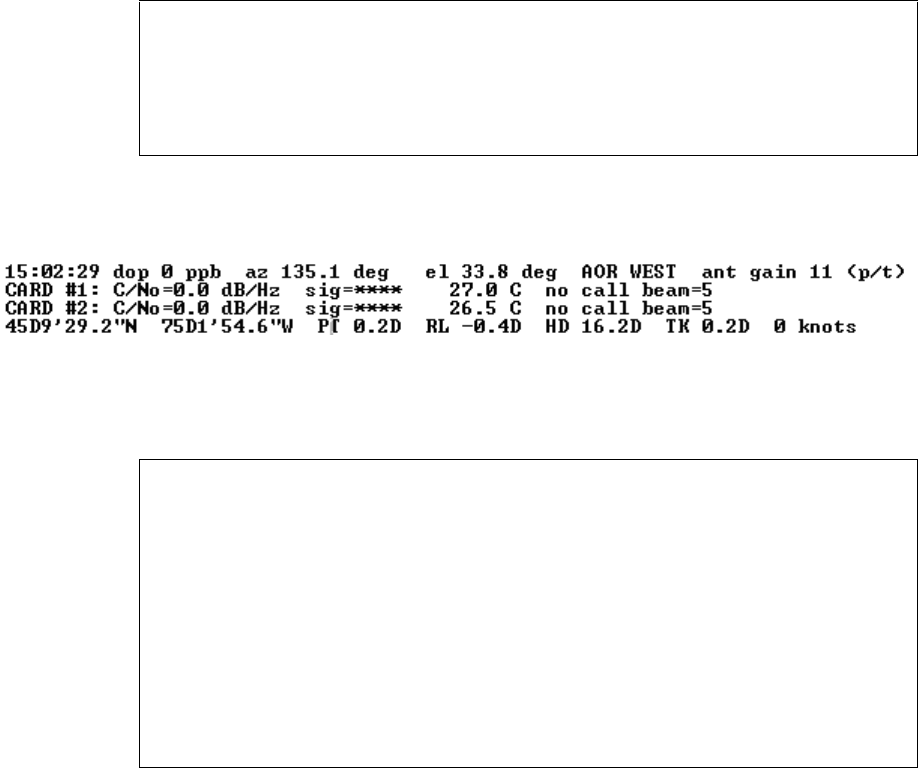
Page 4–83
18 September 2007
SYSTEM DESCRIPTION, INSTALLATION, AND MAINTENANCE MANUAL
eNfusion™ HSD-128 High-speed Data Terminal
Figure 4–51. No IRS Data: Report 23 activated
Figure 4–52. No Signal: Report 23 activated
Figure 4–53. Failed Ocean Region Registration: Report 21 activated
12:43:55 dop**** az 285.4 deg el 15.3 deg AOR EAST ant gain 11 (p/t)
CARD #1: C/No=52.9 dB/Hz sig=-16.9 dB 27 C no call beam=4
CARD #2: C/No=52.9 dB/Hz sig=-18.2 dB 27 C no call beam=4
************ *********** ********* ******** ********* ******* *******
CARD #1: C/No=52.4.0 dB/Hz sig=-17.6 dB 27 C in call beam=4
CARD #2: C/No=52.4 dB/Hz sig=-18.5 dB 27 C no call beam=4
************ *********** ********* ******** ********* ******* *******
15:01:27 #2 ABC123 W5 call term 8306 26.0 C
15:01:29 #1 DEF456 W5 call init 4000110 14.00 dbw SP Ocean Region
Registration 2 7.0 C
15:01:30 #2 ABC123 W5 call init 4000110 14.00 dbw SP Ocean Region
Registration 2 6.0 C
15:01:35 #1 DEF456 W5 call term 8306 27.0 C
15:01:36 #2 ABC123 W5 call term 8306 26.5 C
15:01:37 #1 DEF456 W5 call init 4000110 14.00 dbw SP Ocean Region
Registration 2 7.0 C
15:01:39 #2 ABC123 W5 call init 4000110 14.00 dbw SP Ocean Region
Registration 2 6.5 C
15:01:43 #1 DEF456 W5 call term 8302 ACSE Failed ORR 27.0 C
15:01:45 #2 ABC123 W5 call term 8302 ACSE Failed ORR 26.5 C

Page 4–84
18 September 2007
SYSTEM DESCRIPTION, INSTALLATION, AND MAINTENANCE MANUAL
eNfusion™ HSD-128 High-speed Data Terminal
Figure 4–54. Forward ID Not Strapped: No reports activated
10:00:35 Tue Jun 3, 2003
KERNEL Vx.x -- Mon Oct 07 13:36:26 2002
TESTING RAM ......RAM OK.
HSD APPLICATION Vx.x -- Thu Apr 24 13:28:58 2003
Type "menu" to activate the maintenance port menus.
Other passwords provide different levels of authorization.
fault log sector 15 contains 1384 entries
REAL TIME CLOCK PRESENT: 10:00:55 Tue Jun 3, 2003
**** strapping identifies forward id ffffff -- not in table *****
**** eeprom forward id 0 not in table *****
EEPROM forces STAND-ALONE MODE
!!ensure that arinc test data doesn't bother sat906
powering up channel card #1
powering up channel card #2
SENDING FIRST OC_RESTART COMMAND
!!CARD #2 -- CONTROL PROCESSOR TRIGGERING OCEAN REGION REG IN AOR EAST!!
SENDING FIRST OC_RESTART COMMAND
!!CARD #1 -- CONTROL PROCESSOR TRIGGERING OCEAN REGION REG IN AOR EAST!!

Page 4–85
18 September 2007
SYSTEM DESCRIPTION, INSTALLATION, AND MAINTENANCE MANUAL
eNfusion™ HSD-128 High-speed Data Terminal
KERNEL Vx.x -- Mon Oct 07 13:36:26 2002
TESTING RAM ......RAM OK.
HSD APPLICATION V4.6 -- Thu Apr 24 13:28:58 2003
Type "menu" to activate the maintenance port menus.
Other passwords provide different levels of authorization.
fault log sector 15 contains 1396 entries
REAL TIME CLOCK PRESENT: 10:09:51 Tue Jun 3, 2003
channel card forward id ABC123
EEPROM forces STAND-ALONE MODE
!!ensure that arinc test data doesn't bother sat906
powering up channel card #1
powering up channel card #2
SENDING FIRST OC_RESTART COMMAND
!!CARD #2 -- CONTROL PROCESSOR TRIGGERING OCEAN REGION REG IN AOR EAST!!
SENDING FIRST OC_RESTART COMMAND
!!CARD #1 -- CONTROL PROCESSOR TRIGGERING OCEAN REGION REG IN AOR EAST!!
Log-on password entered: "Maint"
MENU1 FIRMWARE Vx.x
X override forward id L test LEDs
Y explain hpa error status
<CTRL> N next menu <CTRL> O previous menu = select reports
HPA ERROR CODE 1800
Y command entered:
HPA MAINTENANCE WORD NOT REPORTING HGA ANTENNA
HPA STATUS WORD NOT REPORTING HGA ANTENNA
Event log messages:
MENU 3 FIRMWARE Vx.x
L list EEPROM S list event log
E reset EEPROM C clear event log
M misc. EEPROM parameter J ignored faults
N system serial number F list call log
G clear call log
<CTRL> N next menu <CTRL> O previous menu = select reports
HPA ERROR CODE 1800
hit '0' for complete log '1' for 'special' events '-' for specific entry
FAULT (ENTRY #1428): address ABC123: 30 seconds after powerup
powerup #204 389 hours operation Jun 03 11:19:39 2003
ERROR CODE 40
HPA FAULT -- 0x1800
HPA MAINTENANCE WORD NOT REPORTING HGA ANTENNA
HPA STATUS WORD NOT REPORTING HGA ANTENNA
Continuous Power Requests From LES, Report 21 activated:

Page 4–86
18 September 2007
SYSTEM DESCRIPTION, INSTALLATION, AND MAINTENANCE MANUAL
eNfusion™ HSD-128 High-speed Data Terminal
Figure 4–55. No Strap on SDI Lines (open): No reports activated
10:51:26 #2 ABC456 E5 start 400110 14.00 dBW CT SP ocean region
registration 30 C 54 dB/Hz
10:51:26 #1 ABC123 E5 start 400110 14.00 dBW CT SP ocean region
registration 29 C 54 dB/Hz
10:51:27 #2 ABC456 E5 start 400110 14.00 dBW CT SP ocean region
registration 30 C
10:51:27 #1 ABC123 E5 start 400110 14.00 dBW CT SP ocean region
registration 29 C
10:51:27 #1 ABC123 E5 start 400110 14.00 dBW CT SP ocean region
registration 29 C 0 dB/Hz
10:51:27 #2 ABC456 E5 start 400110 14.00 dBW CT SP ocean region
registration 30 C 0 dB/Hz
10:51:29 #1 ABC123 E5 start 400110 14.00 dBW CT SP ocean region registration
29 C 54 dB/Hz
10:51:29 #2 ABC456 E5 start 400110 14.00 dBW CT SP ocean region registration
30 C 54 dB/Hz
10:51:29 #2 ABC456 E5 start 400110 14.00 dBW CT SP ocean region
registration 30 C

Page 4–87
18 September 2007
SYSTEM DESCRIPTION, INSTALLATION, AND MAINTENANCE MANUAL
eNfusion™ HSD-128 High-speed Data Terminal
Figure 4–56. Wrong Strap on SDI Lines (TP5A to GND)
Log-on password entered: "Maint"
MENU1 FIRMWARE Vx.x
X override forward id L test LEDs
Y explain hpa error status
<CTRL> N next menu <CTRL> O previous menu = select reports
HPA UNCONTROLLED
Y command entered:
HPA MAINTENANCE WORD REPORTING ARINC ERROR
HPA MAINTENANCE WORD NOT REPORTING HGA ANTENNA
HPA STATUS WORD REPORTING INVALID SSM 1 (NO COMPUTED DATA)
HPA STATUS WORD NOT REPORTING HGA ANTENNA
Event log messages:
MENU 3 FIRMWARE Vx.x
L list EEPROM S list event log
E reset EEPROM C clear event log
M misc. EEPROM parameter J ignored faults
N system serial number F list call log
G clear call log
<CTRL> N next menu <CTRL> O previous menu = select reports
FAULT (ENTRY #1422): address ABC123: 30 seconds after powerup
powerup #203 389 hours operation Jun 03 11:15:07 2003
ERROR CODE 40
HPA FAULT -- 0x1c80
HPA MAINTENANCE WORD REPORTING ARINC ERROR
HPA MAINTENANCE WORD NOT REPORTING HGA ANTENNA
HPA STATUS WORD REPORTING INVALID SSM 1 (NO COMPUTED DATA)
HPA STATUS WORD NOT REPORTING HGA ANTENNA

Page 4–88
18 September 2007
SYSTEM DESCRIPTION, INSTALLATION, AND MAINTENANCE MANUAL
eNfusion™ HSD-128 High-speed Data Terminal
Figure 4–57. Stand-Alone Mode Multi-Control Loopback (TP1A-3E & TP1B-3F) Not
Wired: HSD Fault LED “ON”
Figure 4–58. Incorrect Dialing Format: Reports 21 and 52 Enabled
MENU1 FIRMWARE Vx.x
X override forward id L test LEDs
Y explain hpa error status
<CTRL> N next menu <CTRL> O previous menu = select reports
HPA UNCONTROLLED
Y command entered:
HPA MAINTENANCE WORD REPORTING ARINC ERROR
HPA STATUS WORD REPORTING INVALID SSM 1 (NO COMPUTED DATA)
Event log messages:
MENU 3 FIRMWARE Vx.x
L list EEPROM S list event log
E reset EEPROM C clear event log
M misc. EEPROM parameter J ignored faults
N system serial number F list call log
G clear call log
<CTRL> N next menu <CTRL> O previous menu = select reports
FAULT (ENTRY #1442): address 4ff7d4: 30 seconds after powerup
powerup #207 389 hours operation Jun 03 11:33:02 2003
ERROR CODE 40
HPA FAULT -- 0x480
HPA MAINTENANCE WORD REPORTING ARINC ERROR
HPA STATUS WORD REPORTING INVALID SSM 1 (NO COMPUTE
11:47:43 #2 ABC456 E4 stop 8301 ACSE successful ORR 30 C 50 dB/Hz
11:47:46 #1 ABC123 E5 stop 8301 ACSE successful ORR 28 C 50 dB/Hz
11:47:55 #1 ABC123 E5 start 800124 14.00 dBW mobile aero 64k speech 29
C 47 dB/Hz
11:47:57 #1 ABC123 E5 start 800124 22.50 dBW mobile aero 64k speech 28
C 47 dB/Hz
calling 0116135919064#
11:48:10 #1 ABC123 E5 stop 11d2 call failed, insufficient digits in service
address 28 C 0
calling 0116135919064#

Page 4–89
18 September 2007
SYSTEM DESCRIPTION, INSTALLATION, AND MAINTENANCE MANUAL
eNfusion™ HSD-128 High-speed Data Terminal
Figure 4–59. Top/Port Antenna Status: Reports 18,19, and 20 activated
Figure 4–60. AMBE Call (Mobile-to-Fixed) MES Terminated: Report 21 activated
Figure 4–61. AMBE Call (Mobile-to-Fixed) Terrestrial Terminated: Report 21
activated
Enter 1 thru 67 to toggle report on/off
X turn off all reports <CTRL> N show next page S save to EEPROM
ESC return to PREVIOUS MENU
1 OFF messages to channel card #1 13 OFF messages to channel card #2
2 OFF hex output to channel card #1 14 OFF hex output to channel card #2
3 OFF responses from channel card #1 15 OFF responses from channel card #2
4 OFF hex input from channel card #1 16 OFF hex input from channel card #2
5 OFF channel #1 misc info 17 OFF channel #2 misc info
6 OFF sb antenna arinc input 18 ON port antenna arinc input
7 OFF sb antenna maintenance word 19 ON port antenna maintenance word
8 OFF sb antenna status word 20 ON port antenna status word
9 OFF channel card call status 21 OFF call codes
10 OFF channel card THA codes 22 OFF spot beam selection
11 OFF channel card errors 23 OFF
OMNIDIRECTIONAL MODE open loop tracking port/top active HGA LNA on
port maintenance 0x00600003
port ant: status 608033 SDI=ACU gain 12 maint 600003 SDI=ACU
port ant: status 608033 SDI=ACU gain 12 maint 600003 SDI=ACU
port ant: status 608033 SDI=ACU gain 12 maint 600003 SDI=ACU
port ant: status 608033 SDI=ACU gain 12 maint 600003 SDI=ACU
port ant: status 608033 SDI=ACU gain 12 maint 600003 SDI=ACU
port status: 0x608033 SDI: ACU SSM: NORMAL OPERATION gain: 12
OMNIDIRECTIONAL MODE open loop tracking port/top active HGA LNA on
port maintenance 0x00600003
port ant: status 608033 SDI=ACU gain 12 maint 600003 SDI=ACU
port ant: status 608033 SDI=ACU gain 12 maint 600003 SDI=ACU
port ant: status 608033 SDI=ACU gain 12 maint 600003 SDI=ACU
port ant: status 608033 SDI=ACU gain 12 maint 600003 SDI=ACU
12:31:25 #1 ABC123 E4 start 800103 14.00 dBW mobile AMBE 28 C 47 dB/Hz
12:31:27 #1 ABC123 E4 start 800103 14.00 dBW mobile AMBE 28 C 47 dB/Hz
12:31:38 #1 ABC123 E4 start 800103 14.00 dBW mobile AMBE 28 C 44 dB/Hz
12:31:55 #1 ABC123 E4 stop 1001 call cleared by MES terminal 28 C 44 dB/Hz
12:34:27 #1 ABC123 E4 start 800103 14.00 dBW mobile AMBE 28 C 48 dB/Hz
12:34:29 #1 ABC123 E4 start 800103 14.00 dBW mobile AMBE 28 C 48 dB/Hz
12:34:39 #1 ABC123 E4 start 800103 14.00 dBW mobile AMBE 28 C 0 dB/Hz
12:35:31 #1 ABC123 E4 stop 1f01 call cleared by terrestrial circuit 28
C 43 dB/Hz

Page 4–90
18 September 2007
SYSTEM DESCRIPTION, INSTALLATION, AND MAINTENANCE MANUAL
eNfusion™ HSD-128 High-speed Data Terminal
Figure 4–62. 64 K Speech call (Mobile to Fixed) Terrestrial Termination: Reports 21
and 23 activated
12:43:24 #1 ABC123 E4 start 800124 14.00 dBW mobile aero 64k speech 28
C 47 dB/Hz
12:43:24 dop 0 ppb az 285.4 deg el 15.3 deg AOR EAST ant gain 12 (p/t)
CARD #1: C/No=*** sig=-16.4 dB 28 C IDLE IN CALL beam=4
CARD #2: C/No=47.3 dB/Hz sig=-15.2 dB 30 C no call beam=4
45D21'16.1"N 75D0'0.2"W PT -10.0D RL 0.0D HD 185.0D TK 0.2D 0 knots
12:43:25 dop 0 ppb az 285.4 deg el 15.3 deg AOR EAST ant gain 12 (p/t)
CARD #1: C/No=47.3 dB/Hz sig=-16.4 dB 28 C in call beam=4
CARD #2: C/No=47.3 dB/Hz sig=-15.0 dB 30 C no call beam=4
45D21'16.1"N 75D0'0.2"W PT -10.0D RL 0.0D HD 185.0D TK 0.2D 0 knots
12:43:26 dop 0 ppb az 285.4 deg el 15.3 deg AOR EAST ant gain 12 (p/t)
CARD #1: C/No=47.3 dB/Hz sig=-16.8 dB 28 C in call beam=4
CARD #2: C/No=47.3 dB/Hz sig=-15.4 dB 30 C no call beam=4
45D21'16.1"N 75D0'0.2"W PT -10.0D RL 0.0D HD 185.0D TK 0.2D 0 knots
12:43:26 #1 ABC123 E4 start 800124 22.50 dBW mobile aero 64k speech 28 C
12:43:27 dop 0 ppb az 285.4 deg el 15.3 deg AOR EAST ant gain 12 (p/t)
CARD #1: C/No=0.0 dB/Hz sig=-999.9 dB 28 C in call beam=4
CARD #2: C/No=47.4 dB/Hz sig=-15.6 dB 30 C no call beam=4
45D21'16.1"N 75D0'0.2"W PT -10.0D RL 0.0D HD 185.0D TK 0.2D 0 knots
12:43:42 dop 0 ppb az 285.4 deg el 15.3 deg AOR EAST ant gain 12 (p/t)
CARD #1: C/No=54.1 dB/Hz sig=-11.6 dB 28 C in call beam=4
CARD #2: C/No=46.9 dB/Hz sig=-15.8 dB 30 C no call beam=4
45D21'16.1"N 75D0'0.2"W PT -10.0D RL 0.0D HD 185.0D TK 0.2D 0 knots
12:43:43 #1 ABC123 E4 start 800124 21.50 dBW mobile aero 64k speech 28
C 0 dB/Hz
12:43:43 dop 0 ppb az 285.4 deg el 15.3 deg AOR EAST ant gain 12 (p/t)
CARD #1: C/No=*** sig=-11.6 dB 28 C in call beam=4
CARD #2: C/No=46.8 dB/Hz sig=-15.5 dB 30 C no call beam=4
12:43:55 dop 0 ppb az 285.4 deg el 15.3 deg AOR EAST ant gain 12 (p/t)
CARD #1: C/No=0.0 dB/Hz sig=-10.7 dB 28 C in call beam=4
CARD #2: C/No=46.6 dB/Hz sig=-15.3 dB 30 C no call beam=4
45D21'16.1"N 75D0'0.2"W PT -10.0D RL 0.0D HD 185.0D TK 0.2D 0 knots
12:43:55 #1 ABC123 E4 start 800124 21.50 dBW mobile aero 64k speech 28 C
12:43:56 dop 0 ppb az 285.4 deg el 15.3 deg AOR EAST ant gain 12 (p/t)
CARD #1: C/No=0.0 dB/Hz sig=-999.9 dB 28 C in call beam=4
CARD #2: C/No=47.1 dB/Hz sig=-15.5 dB 30 C no call beam=4
45D21'16.1"N 75D0'0.2"W PT -10.0D RL 0.0D HD 185.0D TK 0.2D 0 knots
12:43:58 dop 0 ppb az 285.4 deg el 15.3 deg AOR EAST ant gain 12 (p/t)
CARD #1: C/No=0.0 dB/Hz sig=-999.9 dB 28 C in call beam=4
CARD #2: C/No=46.9 dB/Hz sig=-15.8 dB 30 C no call beam=4
45D21'16.1"N 75D0'0.2"W PT -10.0D RL 0.0D HD 185.0D TK 0.2D 0 knots
12:43:58 #1 ABC123 E4 stop 1f01 call cleared by terrestrial circuit 28 C

Page 4–91
18 September 2007
SYSTEM DESCRIPTION, INSTALLATION, AND MAINTENANCE MANUAL
eNfusion™ HSD-128 High-speed Data Terminal
.)
Figure 4–63. 64 K Speech Call (Mobile-to-Fixed) Terrestrial Termination: Reports 21
and 23 activated
12:43:24 #1 ABC123 E4 start 800124 14.00 dBW mobile aero 64k speech 28
C 47 dB/Hz
12:43:24 dop 0 ppb az 285.4 deg el 15.3 deg AOR EAST ant gain 12 (p/t)
CARD #1: C/No=*** sig=-16.4 dB 28 C IDLE IN CALL beam=4
CARD #2: C/No=47.3 dB/Hz sig=-15.2 dB 30 C no call beam=4
45D21'16.1"N 75D0'0.2"W PT -10.0D RL 0.0D HD 185.0D TK 0.2D 0 knots
12:43:25 dop 0 ppb az 285.4 deg el 15.3 deg AOR EAST ant gain 12 (p/t)
CARD #1: C/No=47.3 dB/Hz sig=-16.4 dB 28 C in call beam=4
CARD #2: C/No=47.3 dB/Hz sig=-15.0 dB 30 C no call beam=4
45D21'16.1"N 75D0'0.2"W PT -10.0D RL 0.0D HD 185.0D TK 0.2D 0 knots
12:43:26 dop 0 ppb az 285.4 deg el 15.3 deg AOR EAST ant gain 12 (p/t)
CARD #1: C/No=47.3 dB/Hz sig=-16.8 dB 28 C in call beam=4
CARD #2: C/No=47.3 dB/Hz sig=-15.4 dB 30 C no call beam=4
45D21'16.1"N 75D0'0.2"W PT -10.0D RL 0.0D HD 185.0D TK 0.2D 0 knots
12:43:26 #1 ABC123 E4 start 800124 22.50 dBW mobile aero 64k speech 28 C
12:43:27 dop 0 ppb az 285.4 deg el 15.3 deg AOR EAST ant gain 12 (p/t)
CARD #1: C/No=0.0 dB/Hz sig=-999.9 dB 28 C in call beam=4
CARD #2: C/No=47.4 dB/Hz sig=-15.6 dB 30 C no call beam=4
45D21'16.1"N 75D0'0.2"W PT -10.0D RL 0.0D HD 185.0D TK 0.2D 0 knots
12:43:42 dop 0 ppb az 285.4 deg el 15.3 deg AOR EAST ant gain 12 (p/t)
CARD #1: C/No=54.1 dB/Hz sig=-11.6 dB 28 C in call beam=4
CARD #2: C/No=46.9 dB/Hz sig=-15.8 dB 30 C no call beam=4
45D21'16.1"N 75D0'0.2"W PT -10.0D RL 0.0D HD 185.0D TK 0.2D 0 knots
12:43:43 #1 ABC123 E4 start 800124 21.50 dBW mobile aero 64k speech 28
C 0 dB/Hz
12:43:43 dop 0 ppb az 285.4 deg el 15.3 deg AOR EAST ant gain 12 (p/t)
CARD #1: C/No=*** sig=-11.6 dB 28 C in call beam=4
CARD #2: C/No=46.8 dB/Hz sig=-15.5 dB 30 C no call beam=4
12:43:55 dop 0 ppb az 285.4 deg el 15.3 deg AOR EAST ant gain 12 (p/t)
CARD #1: C/No=0.0 dB/Hz sig=-10.7 dB 28 C in call beam=4
CARD #2: C/No=46.6 dB/Hz sig=-15.3 dB 30 C no call beam=4
45D21'16.1"N 75D0'0.2"W PT -10.0D RL 0.0D HD 185.0D TK 0.2D 0 knots
12:43:55 #1 ABC123 E4 start 800124 18.50 dBW mobile aero 64k speech 28 C
12:43:56 dop 0 ppb az 285.4 deg el 15.3 deg AOR EAST ant gain 12 (p/t)
CARD #1: C/No=0.0 dB/Hz sig=-999.9 dB 28 C in call beam=4
CARD #2: C/No=47.1 dB/Hz sig=-15.5 dB 30 C no call beam=4
45D21'16.1"N 75D0'0.2"W PT -10.0D RL 0.0D HD 185.0D TK 0.2D 0 knots
12:43:58 dop 0 ppb az 285.4 deg el 15.3 deg AOR EAST ant gain 12 (p/t)
CARD #1: C/No=0.0 dB/Hz sig=-999.9 dB 28 C in call beam=4
CARD #2: C/No=46.9 dB/Hz sig=-15.8 dB 30 C no call beam=4
45D21'16.1"N 75D0'0.2"W PT -10.0D RL 0.0D HD 185.0D TK 0.2D 0 knots
12:43:58 #1 ABC123 E4 stop 1f01 call cleared by terrestrial circuit 28 C

Page 4–92
18 September 2007
SYSTEM DESCRIPTION, INSTALLATION, AND MAINTENANCE MANUAL
eNfusion™ HSD-128 High-speed Data Terminal
Figure 4–64. Speech Call (Fixed-to-Mobile) Terrestrial Terminated: Report 21
activated
Figure 4–65. FAX Call (Mobile-to-Fixed) Terrestrial Terminated: Report 21 activated
13:40:53 Tue Jun 3, 2003
13:41:22 #1 ABC123 E4 start c00124 14.00 dBW fixed aero 64k speech 28 C
47 dB/Hz
13:41:25 #1 ABC123 E4 start c00124 22.50 dBW fixed aero 64k speech 28 C
48 dB/Hz
13:41:35 #1 ABC123 E4 start c00124 18.50 dBW fixed aero 64k speech 28 C
53 dB/Hz
13:41:41 #1 ABC123 E4 start c00124 19.50 dBW fixed aero 64k speech 28 C
52 dB/Hz
13:41:45 #1 ABC123 E4 stop 1f01 call cleared by terrestrial circuit 28
C 52 dB/Hz
13:31:06 #2 ABC456 E4 start 800625 14.00 dBW mobile aero 64k audio 3k1
30 C 48 dB/Hz
13:31:17 #2 ABC456 E4 start 800625 22.50 dBW mobile aero 64k audio 3k1
30 C 48 dB/Hz
13:31:28 #2 ABC456 E4 start 800625 22.50 dBW mobile aero 64k audio 3k1
30 C 55 dB/Hz
13:31:40 #2 ABC456 E4 start 800625 21.50 dBW mobile aero 64k audio 3k1
30 C 0 dB/Hz
13:31:46 #2 ABC456 E4 start 800625 20.50 dBW mobile aero 64k audio 3k1
30 C 55 dB/Hz
13:31:52 #2 ABC456 E4 start 800625 19.50 dBW mobile aero 64k audio 3k1
30 C 0 dB/Hz
13:31:58 #2 ABC456 E4 start 800625 20.50 dBW mobile aero 64k audio 3k1
30 C 0 dB/Hz
13:32:04 #2 ABC456 E4 start 800625 20.50 dBW mobile aero 64k audio 3k1
30 C 0 dB/Hz
13:32:10 #2 ABC456 E4 start 800625 20.50 dBW mobile aero 64k audio 3k1
30 C 0 dB/Hz
13:32:17 #2 ABC456 E4 start 800625 19.50 dBW mobile aero 64k audio 3k1
30 C 0 dB/Hz
13:32:23 #2 ABC456 E4 start 800625 20.50 dBW mobile aero 64k audio 3k1
30 C 0 dB/Hz
13:32:29 #2 ABC456 E4 start 800625 19.50 dBW mobile aero 64k audio 3k1
30 C 0 dB/Hz
13:32:32 #2 ABC456 E4 stop 1f01 call cleared by terrestrial circuit 30
C 0 dB/Hz

Page 4–93
18 September 2007
SYSTEM DESCRIPTION, INSTALLATION, AND MAINTENANCE MANUAL
eNfusion™ HSD-128 High-speed Data Terminal
Figure 4–66. 64 K Speech and Data Call (Mobile-to-Fixed) MES Terminated: Report
21 activated
(2) Troubleshooting Table
Table 4–27 provides fixes for basic HSD system faults. Before completing any fix,
activate the HSD Maintenance Utility Program using the “maint” password. For
detailed connection and user instructions, refer to "HSD Maintenance Utility Program"
on page 4-3.
13:33:27 Tue Jun 3, 2003
13:38:22 #2 ABC456 E4 start 800622 14.00 dBW mobile aero 64k UDI 30 C
47 dB/Hz
13:38:25 #2 ABC456 E4 start 800622 22.50 dBW mobile aero 64k UDI 30 C
47 dB/Hz
13:38:35 #1 ABC123 E4 start 800124 14.00 dBW mobile aero 64k speech 28
C 47 dB/Hz
13:38:36 #2 ABC456 E4 start 800622 22.50 dBW mobile aero 64k UDI 30 C
55 dB/Hz
13:38:37 #1 ABC123 E4 start 800124 22.50 dBW mobile aero 64k speech 28
C 47 dB/Hz
13:38:42 #2 ABC456 E4 start 800622 21.50 dBW mobile aero 64k UDI 30 C 0
dB/Hz
13:38:48 #1 ABC123 E4 start 800124 22.50 dBW mobile aero 64k speech 28
C 54 dB/Hz
13:38:48 #2 ABC456 E4 start 800622 20.50 dBW mobile aero 64k UDI 30 C 0
dB/Hz
13:38:54 #1 ABC123 E4 start 800124 21.50 dBW mobile aero 64k speech 28
C 0 dB/Hz
13:38:54 #2 ABC456 E4 start 800622 19.50 dBW mobile aero 64k UDI 30 C 0
dB/Hz
13:38:53 Tue Jun 3, 2003
13:39:00 #1 ABC123 E4 start 800124 21.50 dBW mobile aero 64k speech 28
C 54 dB/Hz
13:39:00 #2 ABC456 E4 start 800622 19.50 dBW mobile aero 64k UDI 30 C 0
dB/Hz
13:39:06 #1 ABC123 E4 start 800124 21.50 dBW mobile aero 64k speech 28
C 0 dB/Hz
13:39:06 #2 ABC456 E4 start 800622 19.50 dBW mobile aero 64k UDI 30 C 0
dB/Hz
13:39:12 #1 ABC123 E4 start 800124 21.50 dBW mobile aero 64k speech 28
C 55 dB/Hz
13:39:12 #2 ABC456 E4 start 800622 19.50 dBW mobile aero 64k UDI 30 C 0
dB/Hz
13:39:18 #1 ABC123 E4 start 800124 21.50 dBW mobile aero 64k speech 28
C 0 dB/Hz
13:39:19 #2 ABC456 E4 stop 1001 call cleared by MES terminal 30 C 0 dB/Hz
13:39:20 #1 ABC123 E4 stop 1001 call cleared by MES terminal 28 C 0 dB/Hz

Page 4–94
18 September 2007
SYSTEM DESCRIPTION, INSTALLATION, AND MAINTENANCE MANUAL
eNfusion™ HSD-128 High-speed Data Terminal
Table 4–27. Troubleshooting and Fault Isolation
Fault Description Maintenance
Report Check
RED LED
remains on
after
powering up
sequence
• HPA Uncontrolled
•HPA Fault
View initial power-up
display of the HSD
Maintenance Utility
Program
• In Stand-Alone
installations, verify that the
multicontrol, looped back
is wired (out to in)
• In Stand-Alone
installations, check
transmit path between
RFU and HSD
HPA Error
Status
• reporting invalid SSM
• HPA not reporting status
word 143
• HPA not reporting
maintenance word 350
• HPA maintenance word
reporting ARINC error
• HPA maintenance word
not reporting HGA
antenna
• HPA maintenance word
reporting VSWR error
• HPA maintenance word
reporting RAM error
•HPA reporting ROM
error
• HPA maintenance word
reporting power supply
error
• HPA maintenance word
reporting temperature
error
In menu 1, press Y to
obtain an
explanation of the
HPA error status
• Check continuity on
ARINC buses between
HSD and antenna
subsystem
• Check continuity on
ARINC buses between
HSD and SDU
• Verify SDI is strapped
correctly (TP5B to TP5D)
• Check the external power
source is properly
connected and meets
installation requirements
• Check transmit path from
HSD output (MPC1) to the
antenna subsystem (coax
cables, splitters, relays,
etc…)
• Check the RFU TX output
(MPC1) connection to the
HSD input (TPC1)
• Check installation location
meets the RTCA/DO-160D
environmental
specifications
• Check for proper fan-tray
operation and air-cooling.
• Verify the fan-tray plug
distribution is as per the
installation requirements

Page 4–95
18 September 2007
SYSTEM DESCRIPTION, INSTALLATION, AND MAINTENANCE MANUAL
eNfusion™ HSD-128 High-speed Data Terminal
Call failure IRS information not
available
Activate
maintenance
reports 21 and 23
(See Figure 4–51)
• Check that the IRS
systems are powered on
and aligned.
• Check that connections to
the IRS systems are
secured.
• Check the polarity of IRS
input lines.
• If no IRS data is available,
use Menu 10 to manually
input navigational data to
point the antenna to a
preferred satellite location
and try the call again.
Call failure System does not log onto the
broadbeam
Activate
maintenance
reports 21 and 23
(See Figure 4–53)
• Check that the IRS data is
received and valid.
• Ensure that a valid FWD ID
is read
• Verify correct antenna
pointing.
• Ensure LES Access codes
are configured correctly.
• Verify all coax
connections.
Call failure System does not log onto the
correct Ocean Region
Activate
maintenance report
21 and 23
(See Figure 4–53)
• Check that the IRS data is
received and valid.
• Check for antenna
line-of-sight interference.
Call failure Unit is not transmitting Activate
maintenance
reports 21 and 23
Figure 4–52 – No
Signal
• Check for a defective or
loose RF cable.
• Verify the Rx RF level is
acceptable.
• Check RF power level
displayed in Maintenance
Port Menu Report Item 21;
signal strength should be
requested at 14.00 dBW
but in call should increase
to 22.5 dBW.
• Ensure the HSD is secured
properly to the ARINC
connector in the tray.
Table 4–27. Troubleshooting and Fault Isolation
Fault Description Maintenance
Report Check

Page 4–96
18 September 2007
SYSTEM DESCRIPTION, INSTALLATION, AND MAINTENANCE MANUAL
eNfusion™ HSD-128 High-speed Data Terminal
Call failure Forward ID is invalid or
strapped incorrectly
Activate
maintenance report
21
(See Figure 4–54)
To check FWD ID, in
Menu 4, press Q
• The account registration
process has not been
completed. Check your
account status with your
service provider to ensure
that the account
registration has been
processed into the LES
databases and that your
account is valid.
• If in the event log, the
message, “Channel card
stuck in boot state”
appears, check that the
assigned FWD IDs are
strapped correctly.
• If fault code 12B1 appears
in the even log, ensure
FWD ID is valid for the
Inmarsat Terminal
Category (If you replace a
Stand-Alone unit (CAT. A)
with a Non-Stand-Alone
unit (CAT. B), you need to
get new FWD IDs
assigned).
Table 4–27. Troubleshooting and Fault Isolation
Fault Description Maintenance
Report Check

Page 4–97
18 September 2007
SYSTEM DESCRIPTION, INSTALLATION, AND MAINTENANCE MANUAL
eNfusion™ HSD-128 High-speed Data Terminal
Call failure Unit is strapped to an
incorrect system mode of
installation
In menu 3, select
Item L (List
EEPROM)
• Verify the system mode
strapping is correct.
• Reset the system and
observe the initialization
display; it shows the HSD
unit’s powering up,
self-test results. The
Initialization display lists
the installation mode
configuration for the unit.
• If the mode displayed is not
strapped or is incorrectly
strapped, a temporary
setting may be used—in
Menu 3, select M (misc.
EEPROM parameters),
then select parameter 16
(Channel Card Category)
and configure the HSD to
the correct mode (e.g. ‘0’
for SAT-906 ,‘1’ for
Stand-Alone…). Reset the
unit and try the call again.
Call failure Dialing sequence was
incomplete or incorrect
Activate report 21
and 23
Figure 4–48 – No
call
• Verify the number you are
calling and try the number
again.
• Refer to the HSD User’s
Guide for detailed
operating instructions.
• Ensure that you end the
dialing sequence by
pressing # (pound key)—
pressing # at the end of the
dialing string signals the
system to “send” the call.
Log-on
request fails
Unit is not transmitting Activate
maintenance
reports 21 and 23
(See Figure 4–53)
• Check for a defective or
loose cable.
• Check for HPA fault.
• Ensure the HSD is secured
properly to the ARINC
connector in the tray.
Table 4–27. Troubleshooting and Fault Isolation
Fault Description Maintenance
Report Check

Page 4–98
18 September 2007
SYSTEM DESCRIPTION, INSTALLATION, AND MAINTENANCE MANUAL
eNfusion™ HSD-128 High-speed Data Terminal
Log-on
request fails
Unit is not receiving Activate
maintenance
reports 21 and 23
(See Figure 4–52)
• Check for a defective or
loose cable.
• Verify that the Forward ID
is valid, activated, and
strapped correctly.
• Ensure your account is
current and active.
• Check for antenna
line-of-sight interference.
• Ensure the HSD is secured
properly to the ARINC
connector in the tray.
Incoming
call failure
Incoming call shows as a
successful connection in
report 23, but call does not
ring through to the external
device (telephone, computer,
fax).
Activate report
21and 23
• Check the connection
between the HSD and the
external device.
• Check configuration of
external devices is correct.
MSN must be configured
correctly for each device
connected to the system.
• If MSNs are not
programmed in the user
devices, incoming calls will
ring all devices. NOTE:
Zero “0” is an invalid MSN
entry.
Table 4–27. Troubleshooting and Fault Isolation
Fault Description Maintenance
Report Check

Page 4–99
18 September 2007
SYSTEM DESCRIPTION, INSTALLATION, AND MAINTENANCE MANUAL
eNfusion™ HSD-128 High-speed Data Terminal
Log-on
successful,
but fails to
complete
call
Authorization error (fault
code 12C4)
Activate maintenance
reports 21 and 23
(See Figure 4–53 and
Figure 4–51)
• Contact your service
provider to verify that the
forward ID is activated.
• Check that the Forward ID
is strapped correctly.
• Check that IRS data is
available and correct.
• Check that the Veh Rel
Az/EL to Satellite is
correct.
• Check that all coax cable
connections are secure.
• Check that the Rx C/No
value is ≥50dB.
• Check antenna status is
okay.
• Check that the primary and
secondary LES access
codes are valid.
• Contact your service
provider and verify that
they can “see” your Tx
signal. To contact the LES
operator dial 33 #.
• Contact service provider
and request that they place
an incoming call to the unit.
• Check the reported HPA
back-off in report 21;
Signal should initialize at
14 dBW and increase after
handshake to
approximately 22.5 dBW –
then slowly decrease
(Range typically between
18.5 dBW to 21.5 dBW with
a lower limit of 14.5 dBW).
Table 4–27. Troubleshooting and Fault Isolation
Fault Description Maintenance
Report Check

Page 4–100
18 September 2007
SYSTEM DESCRIPTION, INSTALLATION, AND MAINTENANCE MANUAL
eNfusion™ HSD-128 High-speed Data Terminal
HSD is
operating
outside the
normal
environmen
tal
specificatio
ns
Channel card
temperature fault
Activate report 21 or 23 • Check channel card
temperature;
temperatures of over 50° C
to 60° C may cause the
HSD or HSD-X to shut
down.
• Check that the fan tray is
operational.
• Verify that the tray plug
distribution is the same as
presented in the
installation requirements.
Calls do not
complete
and
connection
is not
established
Channel Congestion (fault
code 2024)
Activate report 21
and 23
• Wait five minutes and try
the call again.
• Contact the LES to verify
congestion. To contact the
LES operator, dial 33 #.
No call request sent Activate report 21
and 23
• Verify that the call dial
string is correct; Pressing #
at the end of the dialing
string signals the system to
“send” the call.
• Check that the HSD or
HSD-X power LED flashes
on and off (1 Hz) during a
call request.
• Check that the ISDN cable
is connected correctly and
securely.
Table 4–27. Troubleshooting and Fault Isolation
Fault Description Maintenance
Report Check

Page 4–101
18 September 2007
SYSTEM DESCRIPTION, INSTALLATION, AND MAINTENANCE MANUAL
eNfusion™ HSD-128 High-speed Data Terminal
D. Fault Isolation and Diagnostic Procedures
This section provides basic information required for technical personnel to isolate faults
in HSD and HSD-X transceivers. Where needed, refer to other sections of this manual
(which contain important information to aid in understanding the functionality of the unit) for
additional information.
Fault isolation procedures are usually conducted on equipment that falls within one of the
following categories:
• Units that have failed to pass operational and installation verification procedures
• Units that have failed during service
• Units repaired and returned to service
Maintenance reports are helpful in troubleshooting the HSD system. Capturing
maintenance port information from the HSD or HSD-X transceiver and forwarding the file
to EMS SATCOM technical support staff will assist in troubleshooting suspected HSD
system problems. Instructions on how to activate and save “reports” information is
provided in the next section.
No dial tone
heard in
handset
– – • Confirm ISDN lines are
wired correctly.
• Verify handset connection
is secure.
• Wait a few minutes for the
system to warm-up, then
log-on and try your call
again.
• Check that IRS data is
available.
• Verify that the unit has
completed beam
registration.
Call drops
after
successful
connection
If the RF signal fades
significantly (during a call)
the connection may drop
Note: A sudden, severe
aircraft banking angle may
obstruct the signal
Activate report 21
and 23
• Check signal strength
(C/No ≥ 50 dB).
• Ensure there is a clear,
un-obstructed,
line-of-sight to the satellite.
• Select an alternate satellite
or beam and try your call
again (Note: works if you
are located where more
than one beam overlaps or
satellite is
in-view).
Table 4–27. Troubleshooting and Fault Isolation
Fault Description Maintenance
Report Check
Page 4–102
18 September 2007
SYSTEM DESCRIPTION, INSTALLATION, AND MAINTENANCE MANUAL
eNfusion™ HSD-128 High-speed Data Terminal
Perform all fault isolation procedures provided in this section. Record and document all
test results including: LEDs function and maintenance port data outputs (report items 21
and 23).
Enable report items 18, 19, and 20 (Port) or items 6, 7, and 8 (Starboard) to record antenna,
ACU, and DLNA related faults. Enable other report items as required.
Conduct the fault isolation procedures provided in this section and record the resulting
system information. Then send the system information collected to EMS SATCOM HSD
product support for analysis.
CAUTION: Before proceeding with fault isolation procedures, refer to the advisories
paragraphs in the introduction section of this manual.
(1) Activating and Saving a Diagnostic ‘Reports’ File
Use the following procedure to save or “capture” a troubleshooting report for the HSD
transceiver. Remember to date and save the file. Annotate the file with any system
anomalies or unique operating environments that may in anyway affect system
functionality (e.g., physical location of aircraft or transceiver, Land Earth Station being
used, list of connected devices).
In Multi-Channel systems, activate console mode and select the applicable HSD-X
unit you want to monitor before proceeding with this procedure. (To activate console
mode, in Menu 18, press X.)
1. Open a log file on the maintenance port, terminal program. (If you are using
HyperTerminal, use the “Transfer, capture text” function.)
2. Power the system on or if applicable reset the system.
3. Enter maintenance mode on the maintenance port using maint as the password.
(Access level can be changed using menu 1, L command if the system is running
and the password level is menu.)
4. Press the equals sign (=) key to activate reports 21 and 23 (toggle off all other
report items).
5. Press S to “SAVE” these reports as default. This enables the user to view these
reports on subsequent HSD power-ups or “Reset” entries.
6. Reset the system by: cycling the power to the unit; pressing the reset button on
the HSD front panel; or in menu 2, press Z to reset the system.
7. Log on to the maintenance port using the password: maint
The system should restart and ocean registration will take place (approximately
two minutes).
8. After the Beam Registration process completes, press Ctrl+N to display menu 2.
9. Press V to display the software versions of the system.
10. Make a call from the system or execute the procedure or sequence that causes
the call failure. Make a note of the call progress. For example: Did you get dial
tone? Was the call successful?
11. If applicable, attempt a call from the second channel.
12. Press = to display the current “reports” profile of the system (as noted in step 4).
Page 4–103
18 September 2007
SYSTEM DESCRIPTION, INSTALLATION, AND MAINTENANCE MANUAL
eNfusion™ HSD-128 High-speed Data Terminal
13. To save an alternate “reports” configuration, activate the required items and then
press S (in the “reports” menu) to save to EEPROM.
14. Using Ctrl+N, go to menu 3, and then do one of the following:
• For units operating control processor software earlier than version 5.7, press
L to display EEPROM parameters. (The EEPROM list displays one terminal
screen of information at a time. Press L to display subsequent screens.)
• For units operating control processor software later than version 5.7, press
O to display the ORT List. (The ORT list displays one terminal screen of
information at a time. Press O to display the next screen.)
15. In menu 3, press S (list event log) and then press zero “0” and then press the
period key “.” to list the complete event log.
16. In menu 3, press F (list call log), then press F again (complete log) and then press
the period key “.” to the complete event log.” For extended information, press X.
17. Close the log file on the terminal program.
18. The log file is in text format (.txt file). Open the file and add notes to the beginning
of the file indicating:
• System serial number (from the label on the front of the unit)
• Aircraft and customer name
• Any notes about the problems encountered
• Contact name, telephone number, and e-mail address
• E-mail the log file to EMS Technologies technical support at:
hsd.help@emstechnologies.ca
Page 4–104
18 September 2007
SYSTEM DESCRIPTION, INSTALLATION, AND MAINTENANCE MANUAL
eNfusion™ HSD-128 High-speed Data Terminal
4. Adjustment/Alignment Procedures
A. General
There are no adjustment/alignment procedures required for HSD or HSD-X transceivers.

Page 4–105
18 September 2007
SYSTEM DESCRIPTION, INSTALLATION, AND MAINTENANCE MANUAL
eNfusion™ HSD-128 High-speed Data Terminal
5. Modification History
Table 4–28 lists the modification history for the HSD transceiver. This history is provided to
aid the technician in understanding the reason for issuing a service bulletin and to describe
the changes to the equipment.
Table 4–28. Modification History
Service Bulletin Description of Modification
1110-SB-0001/A Upgrades channel card software to version 3.0. Upgrades the control
processor software to version 4.4. Upgrades accommodate Inmarsat
system change and fix software bugs.
1110-SB-0002/A HPA Mute and ARINC 429 driver repair hardware modification.
Backplane modification to the HPA wiring harness corrected the reverse
biasing of the Mute lines affecting all units installed with a Ball
dual-conformal-array antenna.
1110-SB-0003/A Resolves problems with Cooperative Mode operation
1110-SB-0004/A Hardware upgrade to install Data I/O Type 2 card
1110-SB-0005/B Upgrades the hardware for Honeywell Combined Mode (HCM) to
include a RF detector and a variable attenuator on the Aero H path of
the pre-HPA combiner and allows the reading and control of this
attenuator through a serial connection to the combiner. The control
processor code is upgraded to include processing of the attenuator
settings in the power control algorithm and to allow setting of the
attenuator as part of the combined operation.
This version does not support Cooperative Mode (with SAT-906).
1110-SB-0006/A Channel card software upgrade to support MPDS
1110-SB-0007/A Upgrades the HSD-128 Control Processor software to version 6.5. This
version adds the Multi-Channel capability to the HSD-128 software to
support HSD-128 units integration with external
HSD-X channels (PN 1110-A-0401).
1110-SB-0010/A Hardware upgrade to dual-channel for single channel card transceivers
1110-SB-0011/B Upgrades the Channel Card software to version C35 to fix Cooperative
Mode bug in Channel Card software version C30. Upgrades software
to recognize Cooperative Mode System Config hardware strapping.
1110-SB-0012/A Upgrades the channel card software to version C41 (6.0) which
supports enhanced HSD functionality in all modes of operation,
(including multi-channel configurations) and the use of Inmarsat
services—including AMBE STU capability. In Cooperative Mode
systems, MPDS is not supported with this version of software.
Upgrades the control processor software to version 7.0, which
enhances all modes of operation. Selective Mode units operating
Category A Inmarsat terminals may experience GPS faults when
operating this version of software (workaround: deactivate GPS
protection).
1110-SB-0013/A Adds software identification label to HSD units

Page 4–106
18 September 2007
SYSTEM DESCRIPTION, INSTALLATION, AND MAINTENANCE MANUAL
eNfusion™ HSD-128 High-speed Data Terminal
1110-SB-0014/A Data I/O Type 2 Software Upgrade for units with a Data I/O Type 2 card
installed
1110-SB-0015/B HSD Control Process Software Enhancement
1110-SB-0401/A Upgrades software to support AMBE STU and improve system and
MPDS operation
1110-SB-0402/A Adds software identification label to HSD units
Table 4–28. Modification History
Service Bulletin Description of Modification
Page 5–1
18 September 2007
SYSTEM DESCRIPTION, INSTALLATION, AND MAINTENANCE MANUAL
eNfusion™ HSD-128 High-speed Data Terminal
MAINTENANCE AND REPAIR
1. General
This section provides the maintenance and repair information applicable for all HSD
transceiver models.
2. Maintenance
The HSD Transceiver does not require routine maintenance.
3. Repair
All repair procedures must be completed by EMS SATCOM approved repair facilities.
A. Repair Tools and Supplies
No special supplies are required to repair this equipment.
HSD units that require servicing must be returned to EMS Technologies, Canada or to an
EMS SATCOM approved service center. Refer to "Test and Fault Isolation" on page 4-1
for unit testing requirements and procedures.
B. Repair Procedures
This equipment does not require any special repair procedures.
C. Removal Procedures
If an HSD or HSD-X unit must be removed from service for repair, with power removed,
disconnect all equipment from the unit and then remove it from the ARINC tray.
If an HSD-X unit is removed for servicing, the Multi-Channel HSD system will still operate
(with reduced channel capacity) as long as the HSD-X trays are populated as shown in
Figure 5–1.
With an HSD-X unit removed from the series, the remaining HSD-X units must be moved
so that the empty tray is always the last tray in the installation series. If the RF path is not
equipped with isolators (either separate or built into the combiner), cap all unused splitter
outputs and combiner inputs with 50-ohm terminations.
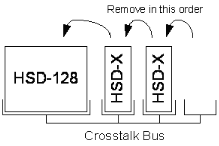
Page 5–2
18 September 2007
SYSTEM DESCRIPTION, INSTALLATION, AND MAINTENANCE MANUAL
eNfusion™ HSD-128 High-speed Data Terminal
Figure 5–1. HSD-X Order of Removal
D. Repair Facility Approvals
The EMS Technologies SATCOM Division, located at 400 Maple Grove Road in Ottawa,
Ontario, Canada, is a Transport Canada Approved Maintenance Organization (AMO). In
accordance with the Technical Arrangement on Maintenance between Canada and the
European aviation authority JAA, and due to the Bilateral Agreement between Canada
and the United States aviation authority FAA, EMS SATCOM conforms to the maintenance
requirements of JAR 145 and FAR 145 respectively.
E. Return for Repair Information
To return equipment to EMS Technologies for repair, follow the Return Materials
Authorization procedure. Failure to comply with this procedure may cause shipping delays
and additional charges.
(1) Warranty Returns
Equipment that qualifies for warranty repair can be returned to EMS SATCOM for
repair or replacement at our discretion. The customer shall pay the shipping costs to
EMS SATCOM and EMS SATCOM will pay for the shipping costs to return the
repaired/replaced unit to the customer.
(2) Non-Warranty Returns
Equipment that fails to work properly because of improper or negligent use, abuse,
shipping damage or any other condition can still be returned to EMS SATCOM for
repair or replacement at our discretion. The customer will be notified of the cost to
repair or replace the unit prior to invoicing for the repair or replacement. The customer
shall pay for the shipping costs to and from EMS Technologies.
(3) Repackaging Requirements
An HSD returned to EMS Technologies must be returned in its original shipping
container. Failure to do so may invalidate the warranty. If an HSD shipping container
is unavailable, the customer must request a replacement container from EMS
SATCOM or assume responsibility for the packaging and shipping.
Page 5–3
18 September 2007
SYSTEM DESCRIPTION, INSTALLATION, AND MAINTENANCE MANUAL
eNfusion™ HSD-128 High-speed Data Terminal
(4) Return Materials Authorization (RMA) Procedure
If it is determined that a unit must be returned to EMS SATCOM for repair or overhaul,
please follow the Return Materials Authorization procedure as follows:
1. Have the following information ready before calling the SATCOM Product’s
Customer Service Center:
• Model number (e.g. HSD);
• Unit part number (e.g. 1110-A-0001);
• Serial number;
• Description of failure;
• Federal ID no. (if applicable); and,
• Purchase Order number (if available).
2. Call EMS Technologies Customer Service at (1-888) 300-7415 or (613) 591-3086.
3. Request an RMA number.
4. Pack the HSD in an EMS SATCOM-approved shipping-container.
5. Write the RMA number on the outside of the shipping container and ship to:
<RMA Number>
EMS Technologies
400 Maple Grove Road
Ottawa, Ontario, CANADA
K2V 1B8
6. Fax shipping details with Way Bill # to the attention of the EMS SATCOM R&O
Coordinator at (613) 591-8951.
Note: The processing of LRU returns is limited to standard business hours from
8:00 am to 4:00 pm EST.
Page 5–4
18 September 2007
SYSTEM DESCRIPTION, INSTALLATION, AND MAINTENANCE MANUAL
eNfusion™ HSD-128 High-speed Data Terminal
4. Instructions for Continued Airworthiness, FAR 25.1529
This section presents the special instructions and maintenance requirements for continued
airworthiness of the HSD High-Speed Data Transceiver.
Installation of the HSD on an aircraft by supplemental type certificate (STC) or Form 337
obligates the aircraft operator to include the maintenance information supplied by this manual
in the operator’s Aircraft Maintenance manual and the operator’s Aircraft Scheduled
Maintenance Program.
A. Instructions for Continued Airworthiness Procedures
The following paragraphs describe all maintenance requirements and instructions for
continued airworthiness of the HSD or HSD-X transceiver.
a. This manual contains maintenance information for the HSD and HSD-X units
(including system description, system operation, removal, installation, test and fault
isolation, and maintenance and repair).
b. Add the LRU part numbers and other necessary part numbers contained in this manual
to the aircraft operator’s appropriate, aircraft illustrated parts catalog (IPC).
c. Add all wiring diagram information contained in this manual to the aircraft operator’s
appropriate aircraft Wiring Diagram Manuals.
d. HSD and HSD-X transceivers are considered on-condition units. No additional or
routine maintenance is required.
e. If an HSD or HSD-X transceiver is inoperative, remove the unit, secure cables and
wiring, collar applicable switches and circuit breakers, and placard them as
“inoperative.” Before flight, revise the equipment list and weight and balance data as
applicable and record the removal of the unit in the log book [refer to section 91.213
of the FAR or the aircraft’s minimum equipment list (MEL)].
f. HSD and HSD-X transceivers are not field-repairable. All units must be returned to
the EMS SATCOM factory or authorized repair centers for repair. Instructions for the
removal of the unit for repair are provided in this section.
g. Repaired units must be re-installed on the aircraft in accordance with the instructions
provided in this manual. The operation of all repaired units must be verified using the
operational verification tests and procedures provided in this manual before being
approved for return to service. All special tools required to test the unit for approval
for return to service are listed and described in "Test and Fault Isolation" on page 4-1.
Approval for return to service must be entered in the logbook as required by section
43.9 of the FAR.
h. The following scheduled maintenance tasks must be added to the aircraft operator’s
appropriate aircraft maintenance program:
• Recommended periodic scheduled servicing tasks: None required.
• Recommended periodic inspections: None required.
• Recommended periodic scheduled preventative maintenance tests (tests to
determine system condition and/or latent failures): None required.
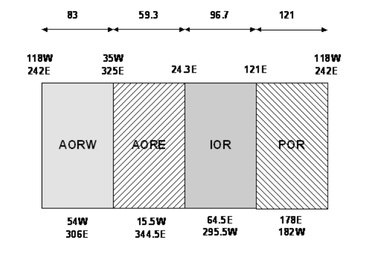
Page A–1
18 September 2007
SYSTEM DESCRIPTION, INSTALLATION, AND MAINTENANCE MANUAL
eNfusion™ HSD-128 High-speed Data Terminal
APPENDIX A: INMARSAT SATELLITE BEAM
COVERAGE
Inmarsat operates four, strategically placed geostationary satellites. Each satellite is
located over and named after an oceanic region. The four satellite ocean regions are:
• Atlantic Ocean Region-East (AOR-E)
• Atlantic Ocean Region-West (AOR-W)
• Indian Ocean Region (IOR)
• Pacific Ocean Region (POR)
The diagram below represents the satellite ocean regions with approximate transfer
coordinates for satellite transitions.
The four satellite ocean regions are made up of smaller, spot-beam coverage areas. The
following maps show the Inmarsat satellite spot-beam coverage for the four ocean
regions—as well as a composite map of the four regions combined.
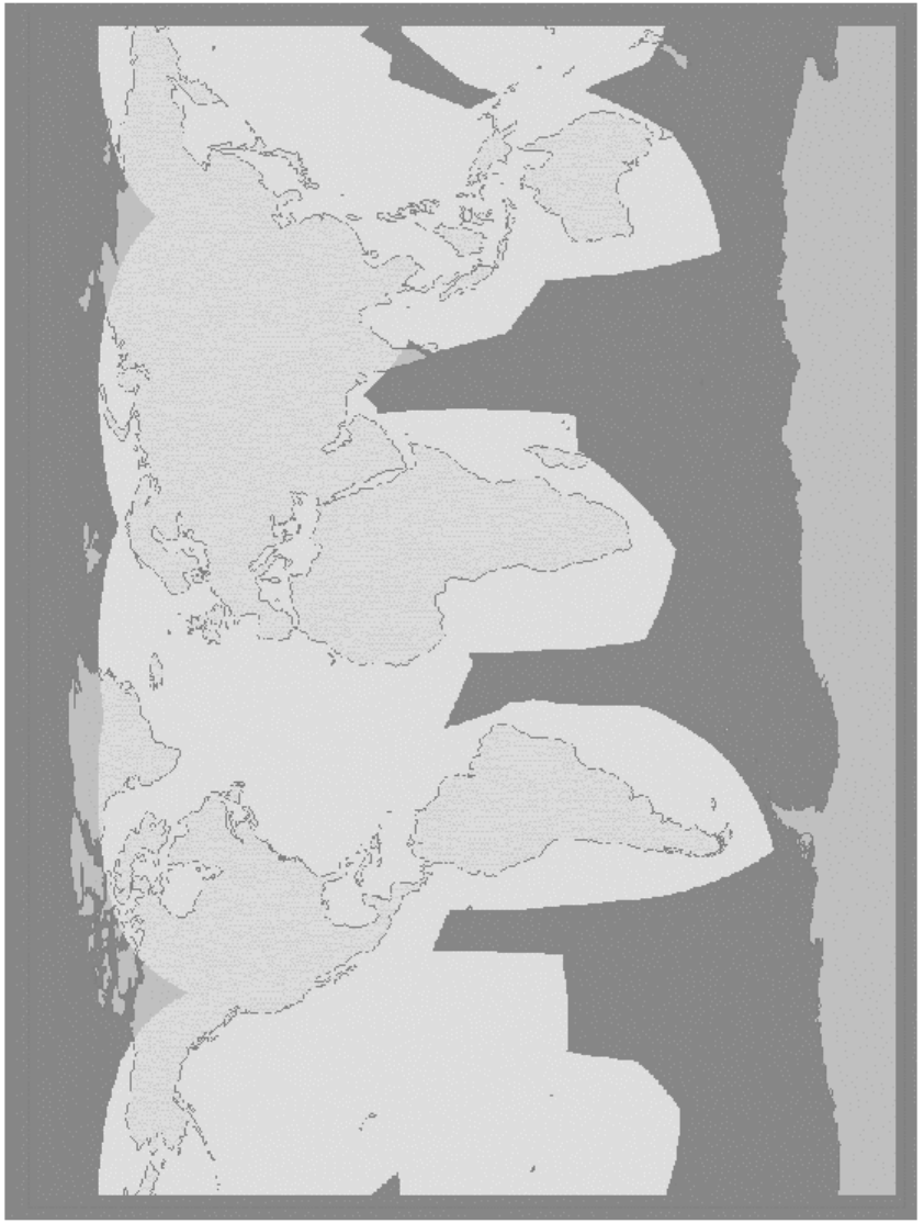
Page A–2
18 September 2007
SYSTEM DESCRIPTION, INSTALLATION, AND MAINTENANCE MANUAL
eNfusion™ HSD-128 High-speed Data Terminal
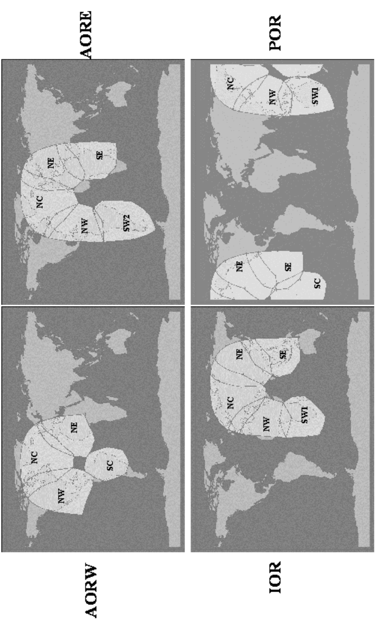
Page A–3
18 September 2007
SYSTEM DESCRIPTION, INSTALLATION, AND MAINTENANCE MANUAL
eNfusion™ HSD-128 High-speed Data Terminal
Page A–4
18 September 2007
SYSTEM DESCRIPTION, INSTALLATION, AND MAINTENANCE MANUAL
eNfusion™ HSD-128 High-speed Data Terminal
Blank Page
Page B–1
18 September 2007
SYSTEM DESCRIPTION, INSTALLATION, AND MAINTENANCE MANUAL
eNfusion™ HSD-128 High-speed Data Terminal
APPENDIX B: TROUBLESHOOTING CHECKLIST
Before proceeding to the detailed testing and troubleshooting procedures provided in this
manual, read the following QuickStart Troubleshooting Checklist. The QuickStart
Troubleshooting Checklist provides answers to common HSD system activation
questions.
1. Have you registered with a service provider to activate service?
You must register with an Inmarsat-authorized service provider to activate an account to
access the Satellite Communications network using an HSD Aeronautical Transceiver.
Contact Inmarsat for a list of available service providers at:
Inmarsat Customer Care
99 City Road, London, EC1Y 1AX
Tel: +44 20 7728 1777
Fax: +44 20 7728 1142
E-mail: customer_care@inmarsat.com
2 Has your account been activated?
Once registered, your HSD Transceiver is assigned terminal identification numbers called
Forward IDs (FWD ID). The HSD transceiver must be strapped accordingly. Refer to
"Installation" on page 3-1 for detailed strapping and installation instructions.
Note: The service registration information may take a few days to be incorporated into
the system databases at the Land Earth Station (LES) level. New units being
commissioned are not validated by the LES until their customer database has been
updated by Inmarsat to reflect the registration and activation of your unit.
To verify that the service registration information has been validated at the LES,
call 33 # for assistance. Confirm with the LES operator that the forward IDs assigned to
your unit are valid and active.
3 Is the HSD/HSD-X transceiver seated properly?
In cases where the HSD or HSD-X is not fully seated into the ARINC 600 connector (to
the rear of the Fan Tray), the user may experience intermittent system operation. If
intermittent system operation occurs:
Check that the polarization pins are installed correctly as indicated on the applicable
Outline and Installation drawing.
Ensure the HSD/HSD-X is fully inserted into the tray and that the front, hold-down screws
are properly tightened to secure the unit.
4 Is all cabling attached correctly and securely?
Broken connections and improper cabling are the most common causes of HSD units “not
working.” Before proceeding with testing and troubleshooting, complete the
following checks:
• Check that all cables and wiring are routed and connected correctly and securely.
• Ensure the unit is installed with correct power source.
• Verify that all external user and networking devices (for example: terminal adapters,
routers, fax, telephones, computers) are connected and configured properly.
Page B–2
18 September 2007
SYSTEM DESCRIPTION, INSTALLATION, AND MAINTENANCE MANUAL
eNfusion™ HSD-128 High-speed Data Terminal
5 Have any changes to the system been made?
For previously installed and functional units, make note of any changes made to the
system since the last time the unit functioned without problems.
• Were any new devices or systems connected to the unit?
• Have any connecting devices or equipment been removed or replaced? If so, check
that all new or replaced connections are attached and configured correctly.
• Have you changed service providers or re-configured the system in any way?
6 Are your Primary and Secondary LES Access Codes programmed for all Ocean
Regions?
In Control Card software versions later than 5.7, the system default for LES access codes
is set to “0” (zero), which must be configured to a valid LES access codes before operation.
Refer to "System Operation" on page 2-1 for details.
7 Was the operational mode of the system strapped or configured correctly?
Verify that the System Mode wiring straps match the installation configuration mode, for
example Stand-Alone Mode, Honeywell Combined Mode (HCM), Cooperative Mode,
Multi-Channel or Selective Mode.
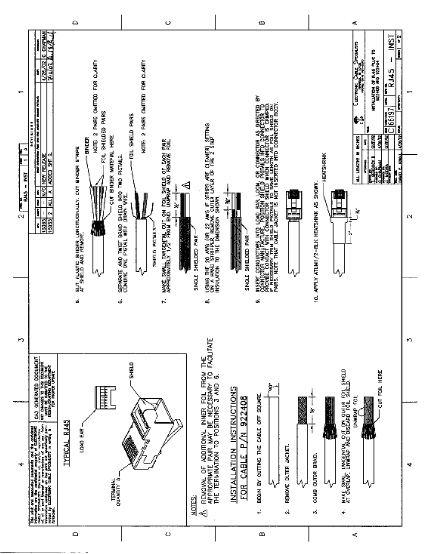
Page C–1
18 September 2007
SYSTEM DESCRIPTION, INSTALLATION, AND MAINTENANCE MANUAL
eNfusion™ HSD-128 High-speed Data Terminal
APPENDIX C: RJ-45 CABLE TERMINATION DETAILS
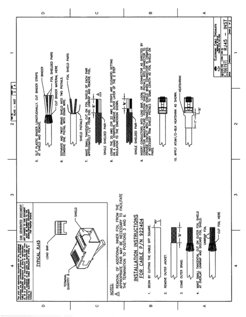
Page C–2
18 September 2007
SYSTEM DESCRIPTION, INSTALLATION, AND MAINTENANCE MANUAL
eNfusion™ HSD-128 High-speed Data Terminal
Page D–1
18 September 2007
SYSTEM DESCRIPTION, INSTALLATION, AND MAINTENANCE MANUAL
eNfusion™ HSD-128 High-speed Data Terminal
APPENDIX D: INSTALLATION CHECKLIST
Aircraft Identification: HSD Model Number:
HSD Installation Mode: HSD Serial Number:
Name: Signature: Date:
Checks completed by:
Approved/witnessed by:
Section Parameter Item N/A RValue
Installation/ Mechanical
Physical Service/maintenance access
Environmental considerations
Fan Tray Plug configuration
Chassis bonding
Fan rotation
ARINC 600 Connector Polarized pins

Page D–2
18 September 2007
SYSTEM DESCRIPTION, INSTALLATION, AND MAINTENANCE MANUAL
eNfusion™ HSD-128 High-speed Data Terminal
Installation/Electrical
Power Connections + 28 V dc polarity
115 V ac polarity
Chassis grounding
Voltage Measurements + 28 V dc level
115 V ac level
IRS Input IRS wiring
IRS format
Configuration Strap Pins SDI
System configuration
Data I/O
Forward Address
WOW (optional)
Ethernet Strapped to RJ45 distribution points
ISDN Strapped to RJ45 distribution points
MPDS Strapped to DB9S distribution
connectors
Remotes Manual Reset switch operation
Remotes Maintenance port (DB9S access)
Power and Fault LED indicators
RF Coax Rx i/p cable loss
Tx o/p cable loss
Antenna Connection Antenna manufacturer and type
Wired as per manufacturer
Multi-control loopbacks installed
Configuration Access codes
Channel cards
Stand-Alone mode
Valid beams
Forward ID
RF i/p attenuation
TEST
System Power-up Visual LED indications
Power-up computer display
TEST
On-air
System Log-on Reset messages observed
Log-on verified
Voice/Data Call Voice/data aircraft all placed
Section Parameter Item N/A RValue

Page D–3
18 September 2007
SYSTEM DESCRIPTION, INSTALLATION, AND MAINTENANCE MANUAL
eNfusion™ HSD-128 High-speed Data Terminal
Operational Test
Tracking results checklist completed
Antenna Tracking Results
Heading
(Deg)
Antenna
selected
Antenna
Azimuth
HSD HSDX
Ch 1 Ch 2 #1 #2
C/NO sig C/NO sig C/NO sig C/NO sig
15
30
45
60
75
90
105
120
135
150
165
180
195
210
225
240
255
270
285
300
315
330
345
360
TEST
Optional Checks Ground segment
Flight segment
Section Parameter Item N/A RValue

Page D–4
18 September 2007
SYSTEM DESCRIPTION, INSTALLATION, AND MAINTENANCE MANUAL
eNfusion™ HSD-128 High-speed Data Terminal
Operational Test
Tracking results checklist completed
Antenna Tracking Results
Heading
(Degrees)
Antenna
selected
Antenna
Azimuth
Card # 1 Card # 2
C/No Signal C/No Signal
15
30
45
60
75
90
105
120
135
150
165
180
195
210
225
240
255
270
285
300
315
330
345
360
TEST
Optional Checks Ground segment
Flight segment
Section Parameter Item N/A RValue
Page E–1
18 September 2007
SYSTEM DESCRIPTION, INSTALLATION, AND MAINTENANCE MANUAL
eNfusion™ HSD-128 High-speed Data Terminal
APPENDIX E: RECORD OF ACCOMPLISHMENT
To record the accomplishment of a software service bulletin, complete a copy of this form
for each unit (serial number) that has been upgraded.
Fax or e-mail all Record of Accomplishments (one for each unit) to EMS Technologies. If
you require assistance, contact EMS SATCOM Product Support.
EMS SATCOM Product Support: 1.888.300.7415 (routed to a mobile after regular
business hours)
E-mail: hsd.help@emstechnologies.ca
FAX:1.613.591.0797
SOFTWARE STATUS AFTER ACCOMPLISHMENT OF SERVICE BULLETIN:
HSD IDENTIFICATION
Part No Serial No
Hardware Revision Software Revision
No. (LI revision)
AIRCRAFT IDENTIFICATION
Type Serial No
Registration (Tail) No
CUSTOMER INFORMATION
Company Phone No
Contact Name Signature
DEALER
Company Phone No
Contact Name Signature
Application Channel Cards HPA Data I/O
HSD HSD-X HSD HSD-X HSD HSD-X HSD HSD-X
Example 4.3 C30 V9A4 DIOMain
1.17.elf
Original
Software
New Software
Installed
Page E–2
18 September 2007
SYSTEM DESCRIPTION, INSTALLATION, AND MAINTENANCE MANUAL
eNfusion™ HSD-128 High-speed Data Terminal
Blank Page
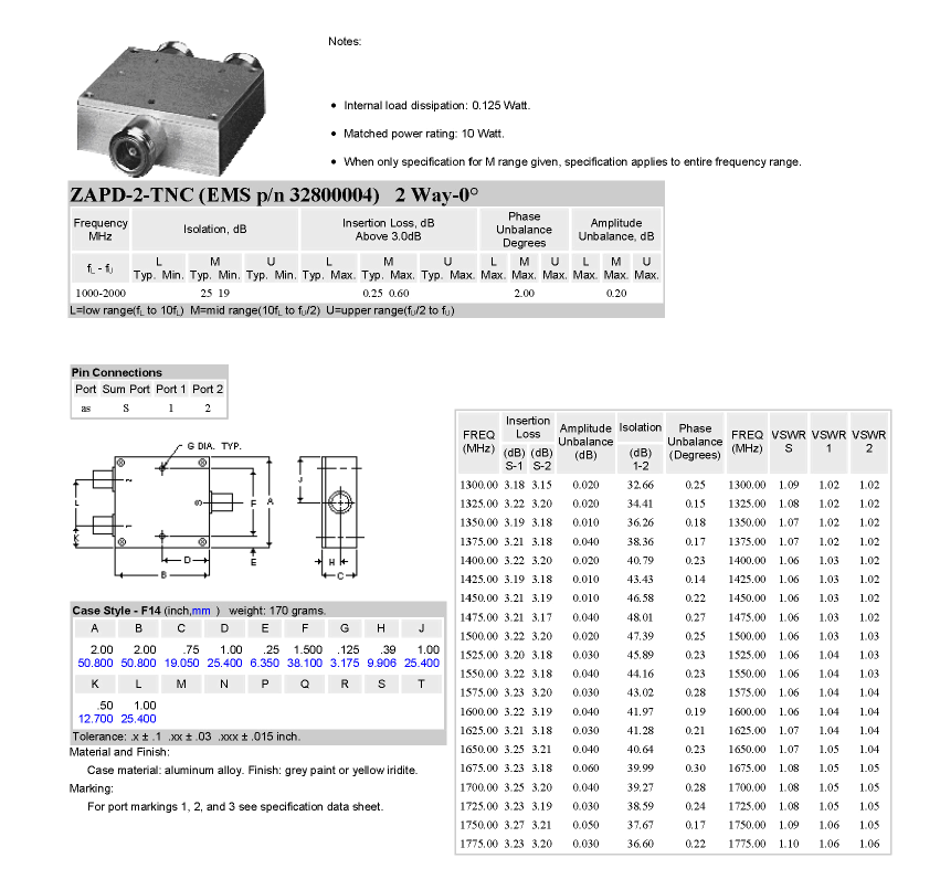
Page F–1
18 September 2007
SYSTEM DESCRIPTION, INSTALLATION, AND MAINTENANCE MANUAL
eNfusion™ HSD-128 High-speed Data Terminal
APPENDIX F: RF SPLITTER
Page F–2
18 September 2007
SYSTEM DESCRIPTION, INSTALLATION, AND MAINTENANCE MANUAL
eNfusion™ HSD-128 High-speed Data Terminal
Blank Page

18 September 2007
SYSTEM DESCRIPTION, INSTALLATION, AND MAINTENANCE MANUAL
eNfusion™ HSD-128 High-speed Data Terminal
Notes

18 September 2007
SYSTEM DESCRIPTION, INSTALLATION, AND MAINTENANCE MANUAL
eNfusion™ HSD-128 High-speed Data Terminal
Notes