EMS Technologies Canada HSD-XI eNfusion HSD-Xi Aeronautical Satcom Terminal User Manual MN 1252 42003
EMS Technologies Canada, Ltd. eNfusion HSD-Xi Aeronautical Satcom Terminal MN 1252 42003
UserManual.wiki
>
EMS Technologies Canada
>
HSD XI User Manual
HSD-Xi User Manual
Navigation menu
Upload a User Manual
Namespaces
Wiki Guide
HTML
PDF
Info
Views
User Manual
Discussion / Help
Navigation


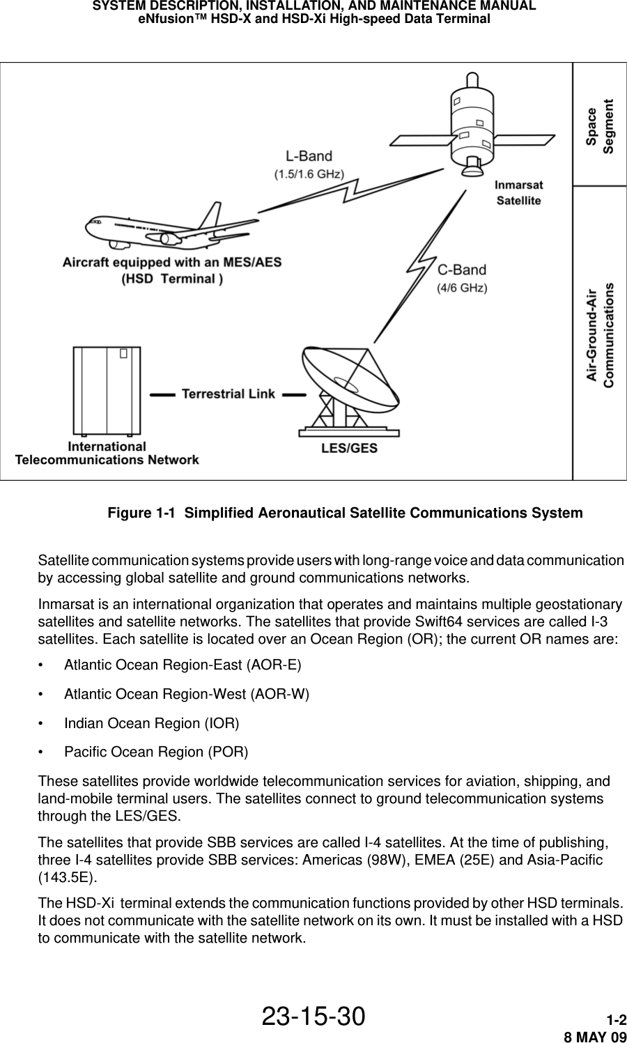


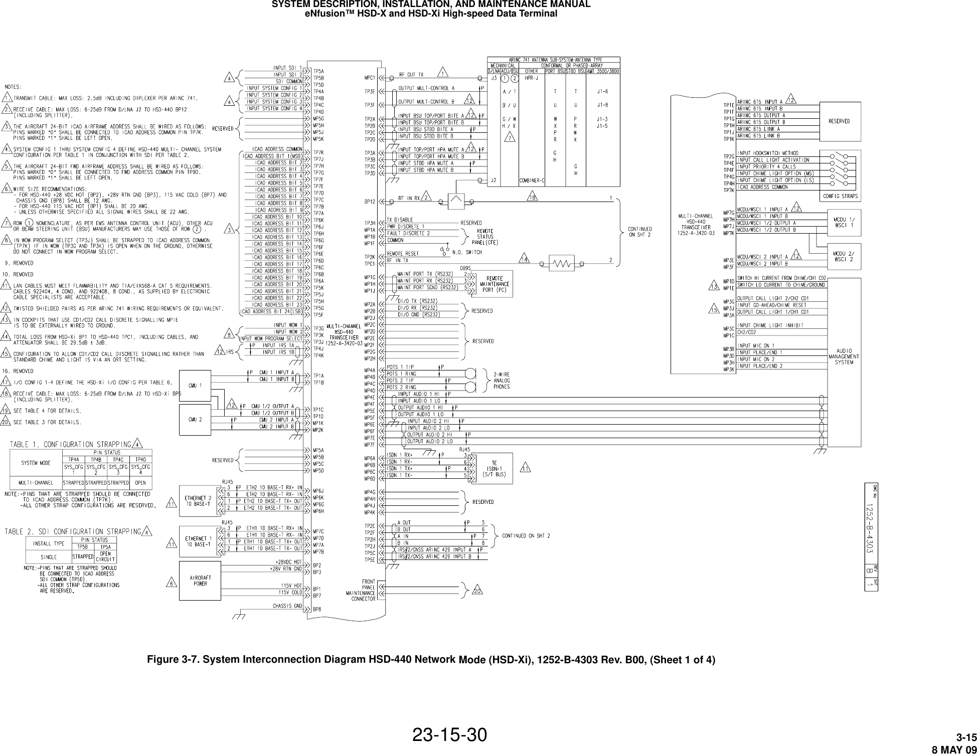

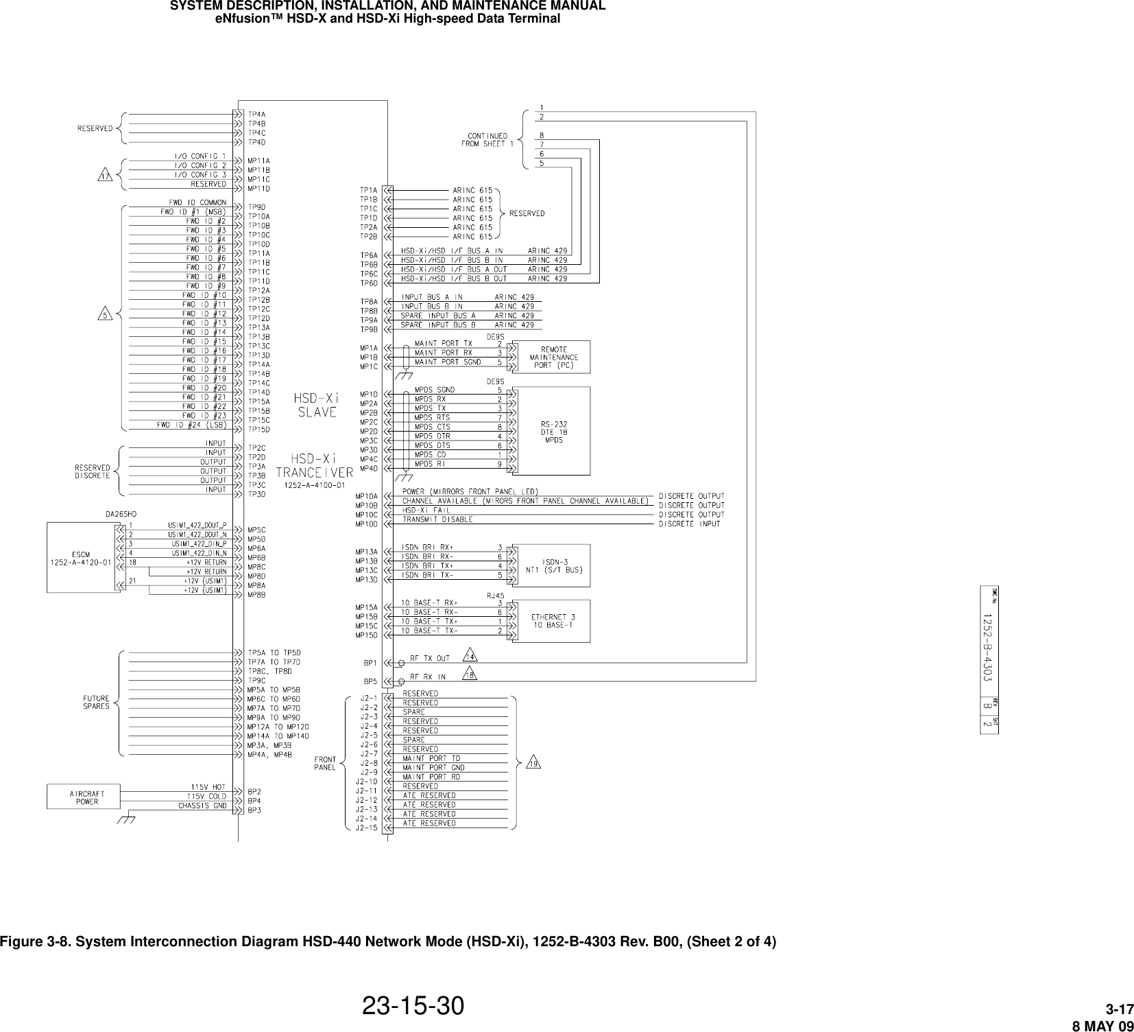

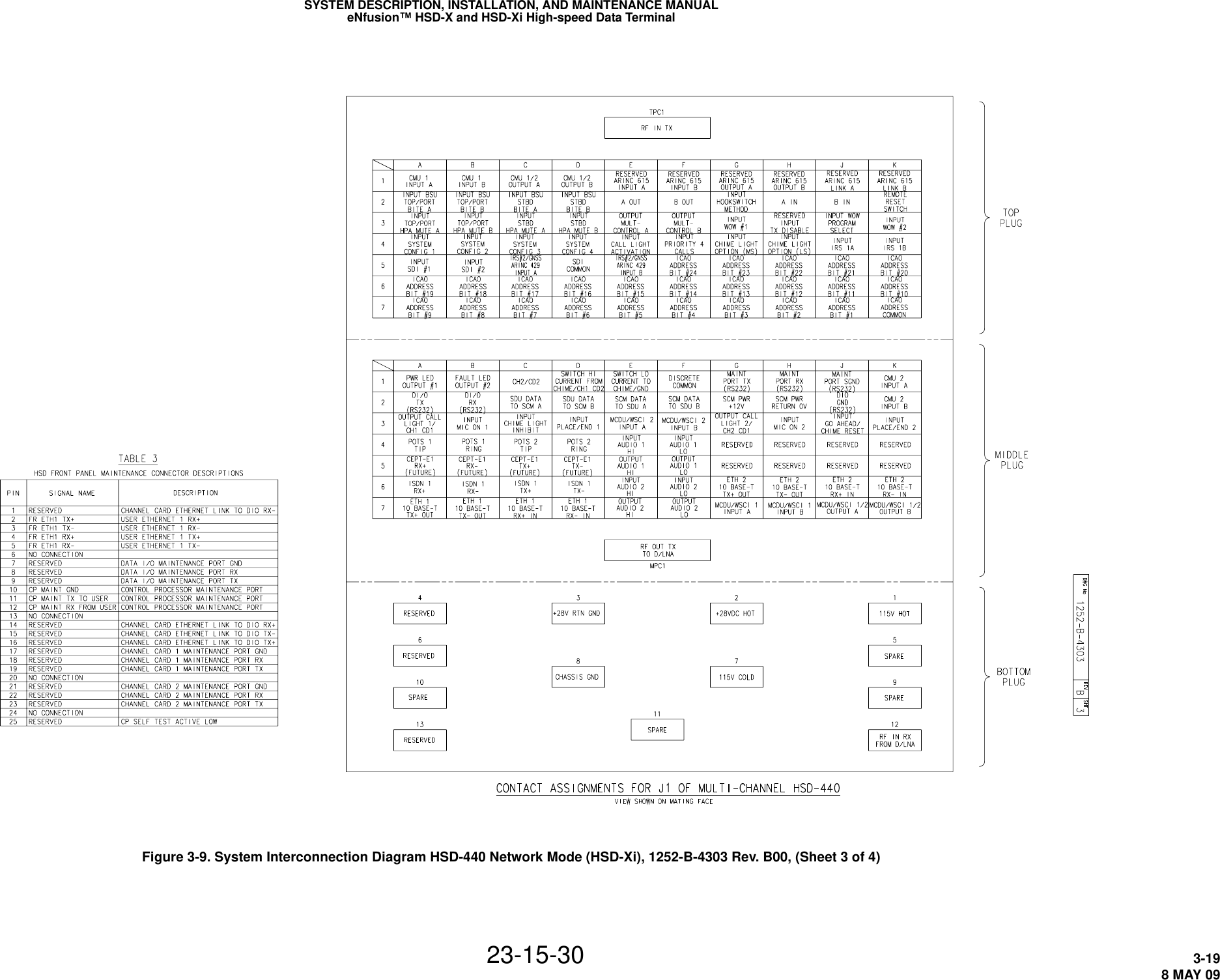


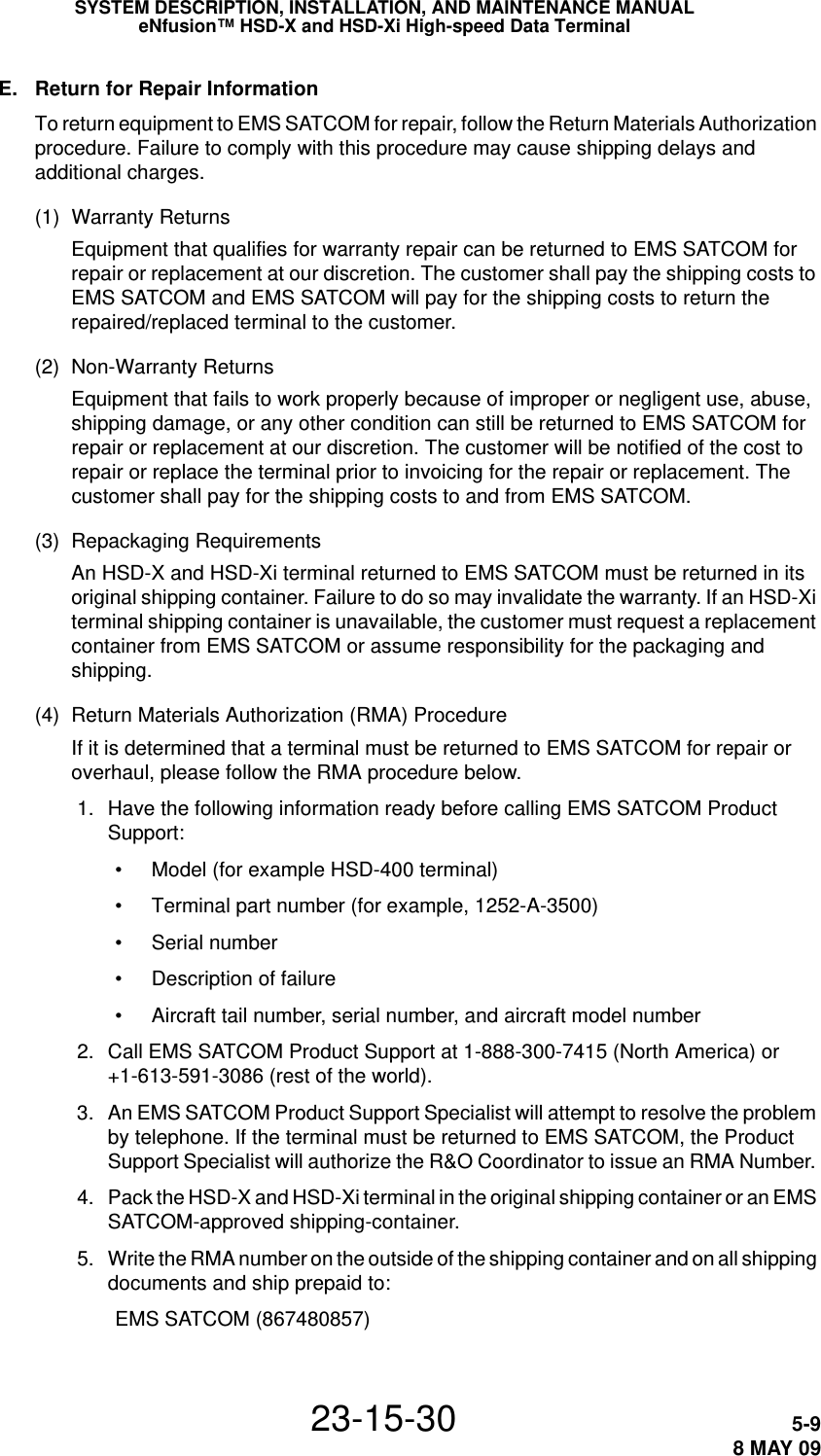
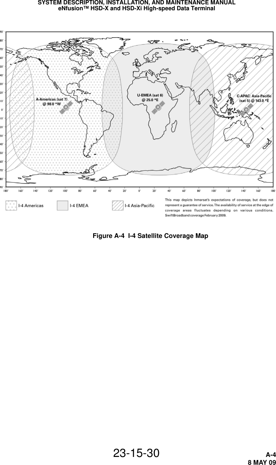
![SYSTEM DESCRIPTION, INSTALLATION, AND MAINTENANCE MANUALeNfusion™ HSD-X and HSD-Xi High-speed Data Terminal23-15-30 5-108 MAY 09400 Maple Grove RoadOttawa, OntarioCanada K2V 1B8RMA#__________ Attn: Repair & Overhaul 6. Fax or email the details of the shipment to the R&O Coordinator, including the following information: Shipment date, carrier name and the waybill number.NOTE: The processing of LRU returns is limited to standard business hours from 8:30 am to 5:00 pm EST. For General inquires and status requests, please contact the R&O department directly:Tel: 613-591-6040 Ext. 1214Fax: 613-591-8951Email: rmareturns@emssatcom.com3. Instructions for Continued AirworthinessThis section presents the instructions for continued airworthiness, as per FAR 25.1529, of the HSD-X and HSD-Xi terminal. Installation of the HSD-X and HSD-Xi terminal on an aircraft by supplemental type certificate (STC) or Form 337 obligates the aircraft operator to include the maintenance information supplied by this manual in the operator's Aircraft Maintenance manual and the operator's Aircraft Scheduled Maintenance Program. The following paragraphs describe all maintenance requirements and instructions for continued airworthiness of the HSD-X and HSD-Xi terminal. • Add the LRU part numbers and other necessary part numbers contained in this manual to the aircraft operator's appropriate, aircraft illustrated parts catalog (IPC).• Add all wiring diagram information contained in this manual to the aircraft operator's appropriate aircraft Wiring Diagram Manuals.• HSD-X and HSD-Xi terminals are considered on-condition units. No additional or routine maintenance is required. • If an HSD-X and HSD-Xi terminal is inoperative, remove the terminal, secure cables and wiring, collar applicable switches and circuit breakers, and placard them as inoperative. Before flight, revise the equipment list and weight and balance data as applicable and record the removal of the terminal in the log book [refer to section 91.213 of the FAR or the aircraft's minimum equipment list (MEL)]. • HSD-X and HSD-Xi terminals are not field-repairable. All terminals must be returned to the EMS SATCOM factory or authorized repair centers for repair.• Repaired terminals must be re-installed on the aircraft in accordance with the instructions provided in this manual. The operation of all repaired terminals must be verified using the operational verification tests and procedures provided in this manual before being approved for return to service. All special tools required to test the terminal for approval for return to service are listed and described in "Test and Fault Isolation" on page 4-1.](https://usermanual.wiki/EMS-Technologies-Canada/HSD-XI/User-Guide-1270750-Page-72.png)