EMS Technologies Canada HSD-440 eNfusion HSD-440 Aeronautical Satcom Transceiver User Manual MN 1252 33077
EMS Technologies Canada, Ltd. eNfusion HSD-440 Aeronautical Satcom Transceiver MN 1252 33077
HSD-440 Users Manual

23-15-30 TITLE PAGE T-1
24 JUN 09
eNfusion™ HSD-440 High-speed Data Terminal
System Description, Installation, and Maintenance Manual
MN-1252-33077, Revision C00
This document provides configuration and operational procedures for the equipment listed below.
Model PN
eNfusion™ HSD-440 High-speed Data Terminal 115 V ac or 28 V dc
eNfusion™ HSD-440 High-speed Data Terminal SBB Mode 115 V ac or 28 V dc
eNfusion™ HSD-440 High-speed Data Terminal SBB Mode 115 V ac or 28 V dc
for Multi-Channel Operation
1252-A-3400
1252-A-3420-02
1252-A-3420-03

23-15-30 TITLE PAGE T-2
24 JUN 09
PROPRIETARY STATEMENT
This document contains information which is proprietary and confidential to EMS SATCOM (EMS
Technologies Canada, Ltd.). Neither this document nor the information contained within may be
used for any purpose other than the purpose for which it was prepared. Neither this document nor
the information contained within may be disclosed or copied without the prior written permission of
EMS SATCOM. © 2007, 2009 EMS Technologies Canada, Ltd. All Rights Reserved.
Cabin Network Xcelerator® and CNX® are registered trademarks of EMS Technologies, Ltd.
Windows is a registered trademark of Microsoft Corporation in the United States and other countries.
Other product, brand, service, and company names herein are the trademarks of their respective
owners.
Our products are under continuous research and development. Any information may therefore be
changed without prior notice. EMS SATCOM reserves the right to make improvements or changes
in the product described in this manual at any time without notice. While reasonable efforts have
been made in the preparation of this document to assure its accuracy, EMS SATCOM assumes no
liability resulting from any errors or omissions in this document, or from the use of the information
contained herein.
Printed in Canada.
EMS SATCOM
400 Maple Grove Road, Ottawa, Ontario, K2V 1B8, CANADA
EMS SATCOM Reception: (613) 591-9064
EMS SATCOM Product Support: (888) 300-7415 (calls are routed to an on-call Product
Support specialist after regular business hours)
+44 1684 290 020 (UK)
(613) 591-3086 (outside North America)
EMS SATCOM E-mail Help: support@emssatcom.com
EMS SATCOM Web site: www.emssatcom.com
EMS SATCOM Sales and Marketing: 800-600-9759
Revision Table
Revision ECR Description
001 N/A Draft release
002 070167 Draft release to benchmark changes
003 070243 Updated environmental specifications table
004 070460 Updated with final software
A00 070701 Official release to customers
B00 080592 Added new part numbers, SCM installation instructions, SBB
updates
C00 090725 Added updated drawing (Rev B) of 1252-E-3420. Updated Table
1-3. Updated return shipping information, Updated I-4 Satellite
info

23-15-30 CR-1
24 JUN 09
CUSTOMER RESPONSE FORM
To help us improve the quality of our product documentation, EMS SATCOM would
appreciate your comments and suggestions on this publication. Please complete the
following customer survey and send to EMS SATCOM at:
EMS SATCOM
400 Maple Grove Road
Ottawa, ON K2V 1B8
E-mail: techdocs@emssatcom.com
Publication information:
Customer information:
Comments and suggestions:
Publication number: MN-1252-33077
Publication title: eNfusion™ HSD-440 High-speed Data Terminal
System Description, Installation, and
Maintenance Manual
Latest issue date: 24 JUN 09
Document revision: C00
Name:
Company:
Tel:
Fax:
Email:
Date:
Comments:
23-15-30 CR-2
24 JUN 09
Blank Page

EMS SATCOM
SYSTEM DESCRIPTION, INSTALLATION, AND MAINTENANCE MANUAL
eNfusion™ HSD-440 High-speed Data Terminal
23-15-30 RR-1
24 JUN 09
RECORD OF REVISIONS
When revisions are received, insert revised pages, record the date, and initial.
Revision
Number Issue
Date Date
Inserted
Inserted
by
(initial)
Revision
Number Issue
Date Date
Inserted
Inserted
by
(initial)
23-15-30 RR-2
24 JUN 09
EMS SATCOM
SYSTEM DESCRIPTION, INSTALLATION, AND MAINTENANCE MANUAL
eNfusion™ HSD-440 High-speed Data Terminal
Blank Page

EMS SATCOM
SYSTEM DESCRIPTION, INSTALLATION, AND MAINTENANCE MANUAL
eNfusion™ HSD-440 High-speed Data Terminal
23-15-30 SBL-1
24 JUN 09
SERVICE BULLETIN LIST
Service
Bulletin
Number Subject Manual Rev.
Number Manual Rev.
Date
1252-SB-3410 Upgrade Software Certification to
Level D B00 22 July 08
1252-SB-3411 Upgrade to Single Channel SBB B00 22 July 08
1252-SB-3412 HSD-440 SBB Upgrade to Level
D Certification C00 24 June 09
1252-SB-3413 Transceiver Software MOD To
Enable Smith MCDU C00 24 June 09
1252-SB-3415 HSD 440 NTWK Upgrade C00 24 June 09
1252-SB-3416 Update HSD ORT Satellite LOC C00 24 June 09
1252-SB-3417 HSD-440 SBB Software Upgrade C00 24 June 09
1252-SB-3418 HSD-440 High-speed Data
Terminal (1252-A-3420) Upgrade
for Network Mode (HSD-X and
HSD-Xi) and SBB Priority Mode
C00 24 June 09
23-15-30 SBL-2
24 JUN 09
EMS SATCOM
SYSTEM DESCRIPTION, INSTALLATION, AND MAINTENANCE MANUAL
eNfusion™ HSD-440 High-speed Data Terminal
Blank Page

EMS SATCOM
SYSTEM DESCRIPTION, INSTALLATION, AND MAINTENANCE MANUAL
eNfusion™ HSD-440 High-speed Data Terminal
23-15-30 LEP-1
24 JUN 09
LIST OF EFFECTIVE PAGES
* An asterisk indicates pages changed, added, or deleted by the current revision.
F indicates a right foldout page with a blank back.
Section Page Date
Title Page T-1 June 8, 2009
11-8 to 1-18 June 8, 2009
22-2, 2-3 June 8, 2009
33-29 to 3-36 June 8, 2009
Service Bulletin List SBL-1 22 Jul 08
Introduction INTRO-2 22 Jul 08
System Description All 22 Jul 08
System Operation All 22 Jul 08
Installation 3-3, 3-14 to 3-32 22 Jul 08
Test and Fault Isolation 4-39, 4-46, 4-50 to 4-55 22 Jul 08
Installation and Planning
Checklist All 22 Jul 08
Service Bulletin List SBL-1 24 JUN 09
System Description 1-2, 1-14, 1-15 24 JUN 09
System Operation 2-9, 2-14 24 JUN 09
Installation 3-10, 3-29, 3-31 24 JUN 09
Test and Fault Isolation 4-2 24 JUN 09
Maintenance and Repair 5-3 24 JUN 09
Appendix A A-4 24 JUN 09
23-15-30 LEP-2
24 JUN 09
EMS SATCOM
SYSTEM DESCRIPTION, INSTALLATION, AND MAINTENANCE MANUAL
eNfusion™ HSD-440 High-speed Data Terminal
Blank Page
EMS SATCOM
SYSTEM DESCRIPTION, INSTALLATION, AND MAINTENANCE MANUAL
eNfusion™ HSD-440 High-speed Data Terminal
23-15-30 TC-1
24 JUN 09
TABLE OF CONTENTS
INTRODUCTION
1. Illustration of Equipment............................................................................... INTRO-2
2. Product Terms and Conditions .................................................................... INTRO-2
3. Reference Documents................................................................................... INTRO-2
4. Acronyms and Abbreviations....................................................................... INTRO-3
5. Safety Advisories........................................................................................... INTRO-6
SYSTEM DESCRIPTION
1. Inmarsat System Overview.................................................................................... 1-1
2. Equipment Overview .............................................................................................. 1-3
3. Equipment Specifications...................................................................................... 1-4
4. Software Description.............................................................................................. 1-8
A. Software Specifications.................................................................................................... 1-8
B. Operational Software Part Numbers ................................................................................ 1-8
5. Mechanical Description.......................................................................................... 1-9
6. Electrical Description............................................................................................. 1-9
7. System Interfaces................................................................................................. 1-10
A. Source Destination Identification (SDI) .......................................................................... 1-11
B. ICAO IDs and Forward IDs ............................................................................................ 1-11
C. Weight-On-Wheel (WOW) Pin Wiring............................................................................ 1-12
D. IRS ARINC 429 Interface............................................................................................... 1-12
E. Antenna Interface........................................................................................................... 1-12
F. Owner’s Requirements Table (ORT)............................................................................... 1-12
G. CMU............................................................................................................................... 1-13
H. MCDU ............................................................................................................................ 1-13
I. Antenna Subsystem RF Interface ................................................................................... 1-13
J. Remote Status Panel (Optional) ..................................................................................... 1-13
K. Fault Conditions ............................................................................................................. 1-14
EMS SATCOM
SYSTEM DESCRIPTION, INSTALLATION, AND MAINTENANCE MANUAL
eNfusion™ HSD-440 High-speed Data Terminal
23-15-30 TC-2
24 JUN 09
L. Remote Reset ................................................................................................................ 1-14
8. User Interfaces...................................................................................................... 1-14
A. ISDN Circuit-Switched Data Interface............................................................................ 1-14
B. Ethernet Data Interfaces ................................................................................................ 1-15
C. ISDN S/T Interface......................................................................................................... 1-16
D. POTS Tip/Ring Interfaces.............................................................................................. 1-16
E. Maintenance Port Interface............................................................................................ 1-16
9. Initiated Self-Test.................................................................................................. 1-16
10. Modes of Operation............................................................................................ 1-17
SYSTEM OPERATION
1. Registering and Activating Terminals .................................................................. 2-1
A. Preparing Terminal Information........................................................................................ 2-1
(1) Obtaining ISNs............................................................................................................ 2-1
(2) Identifying the Service Category and Terminal Type................................................... 2-2
B. Obtaining ICAO Addresses.............................................................................................. 2-2
C. Choosing Service Providers ............................................................................................ 2-2
D. Registering Terminals ...................................................................................................... 2-3
2. Configuring Terminals ........................................................................................... 2-3
A. Setting up Airborne Networks .......................................................................................... 2-3
B. Mapping User Devices for ISDN Services ....................................................................... 2-3
(1) IMNs............................................................................................................................ 2-4
(2) MSNs .......................................................................................................................... 2-5
C. Understanding CMU Messages...................................................................................... 2-6
D. Configuring Terminal Categories ..................................................................................... 2-6
E. Configuring the APN (Access Point Name) ..................................................................... 2-7
F. Configuring LES Access Codes ....................................................................................... 2-7
(1) Changing LES Access Codes using the Control Processor Software ........................ 2-8
(2) Changing LES Access Codes on a Call-by-Call Basis................................................ 2-8
G. Configuring Forward IDs.................................................................................................. 2-8
H. Configuring ORs .............................................................................................................. 2-9
I. Configuring the Channel Cards for Swift64 and SBB...................................................... 2-10
J. Removing the LED Label................................................................................................ 2-11
EMS SATCOM
SYSTEM DESCRIPTION, INSTALLATION, AND MAINTENANCE MANUAL
eNfusion™ HSD-440 High-speed Data Terminal
23-15-30 TC-3
24 JUN 09
K. Activating Configurations ............................................................................................... 2-11
L. Verifying Configurations ................................................................................................. 2-11
3. Using Terminals.................................................................................................... 2-12
A. Placing Swift64 Voice and Fax Calls.............................................................................. 2-12
(1) Dial Code Prefixes .................................................................................................... 2-13
(2) Mobile-to-Mobile Communication.............................................................................. 2-14
B. Using Data Connections ................................................................................................ 2-14
C. Operating the MCDU ..................................................................................................... 2-15
(1) Output Ports.............................................................................................................. 2-15
(2) Input Ports................................................................................................................. 2-15
(3) Screen....................................................................................................................... 2-15
(4) Keyboard................................................................................................................... 2-15
(5) Special Symbols........................................................................................................ 2-16
(6) Navigating the MCDU ............................................................................................... 2-16
(7) Modifying Logon Settings.......................................................................................... 2-17
(8) Viewing Channel Status ............................................................................................ 2-18
(9) Performing Maintenance........................................................................................... 2-23
D. Cockpit Communications ............................................................................................... 2-25
(1) Modes of Operation................................................................................................... 2-25
(2) Accepting and Making Calls...................................................................................... 2-25
INSTALLATION
1. Advisories ............................................................................................................... 3-1
2. Pre-Installation Inspection..................................................................................... 3-1
3. ARINC 600 Trays and Connectors ........................................................................ 3-1
A. Installation Kits................................................................................................................. 3-1
B. Cabling Notes .................................................................................................................. 3-2
(1) Cabling........................................................................................................................ 3-2
(2) Coaxial Cable Loss Considerations ............................................................................ 3-2
4. Mechanical Installation .......................................................................................... 3-2
A. Physical Placement.......................................................................................................... 3-3
B. SCM Installation............................................................................................................... 3-3
C. Environmental Requirements........................................................................................... 3-4
EMS SATCOM
SYSTEM DESCRIPTION, INSTALLATION, AND MAINTENANCE MANUAL
eNfusion™ HSD-440 High-speed Data Terminal
23-15-30 TC-4
24 JUN 09
(1) Heating and Cooling.................................................................................................... 3-4
(2) Fan Tray Requirements .............................................................................................. 3-4
D. Chassis Grounding .......................................................................................................... 3-5
5. Electrical Installation.............................................................................................. 3-5
A. Stand-Alone Mode Installation ......................................................................................... 3-5
(1) Cabling and Connector Requirements........................................................................ 3-5
(2) Installation Wiring Notes ............................................................................................. 3-7
(3) Connection Details.................................................................................................... 3-17
6. Installation and Engineering Diagrams .............................................................. 3-17
A. Outline and Installation Diagrams .................................................................................. 3-17
B. Interconnection and Contact Assignment Drawings ...................................................... 3-17
7. Connection Details ............................................................................................... 3-18
A. Stand-Alone Mode Connection Details .......................................................................... 3-18
TEST AND FAULT ISOLATION
1. Operational and Diagnostic Testing ..................................................................... 4-1
A. General ............................................................................................................................ 4-1
B. Test and Fault Isolation Equipment Requirements .......................................................... 4-1
C. Terminal MPU .................................................................................................................. 4-2
(1) General Overview ....................................................................................................... 4-2
(2) Connection Requirements........................................................................................... 4-3
(3) Accessing the MPU..................................................................................................... 4-5
(4) Using the Terminal MPU ............................................................................................. 4-5
(5) Menu Item Descriptions .............................................................................................. 4-6
(6) Report Descriptions................................................................................................... 4-17
(7) Activating Maintenance Reports ............................................................................... 4-20
D. Fault Definitions............................................................................................................. 4-23
E. Operational and Diagnostic Test Procedures................................................................. 4-23
EMS SATCOM
SYSTEM DESCRIPTION, INSTALLATION, AND MAINTENANCE MANUAL
eNfusion™ HSD-440 High-speed Data Terminal
23-15-30 TC-5
24 JUN 09
(1) General ..................................................................................................................... 4-23
(2) Test Setup Procedure................................................................................................ 4-24
(3) Post Test ................................................................................................................... 4-24
(4) Installation and Operational Verification Tests .......................................................... 4-25
(5) Configuration Parameters Verification....................................................................... 4-27
(6) System Power-up Checks......................................................................................... 4-29
(7) System On-Air Checks.............................................................................................. 4-32
(8) Antenna Tracking Checks......................................................................................... 4-37
(9) Optional System Checks........................................................................................... 4-38
F. Software Load Procedures............................................................................................. 4-39
(1) Loading Channel Card Software............................................................................... 4-39
(2) Loading Control Processor Software ........................................................................ 4-40
(3) Updating Displayed Software Versions..................................................................... 4-41
(4) Verifying Software Loads .......................................................................................... 4-42
(5) Disconnecting Load Equipment ................................................................................ 4-43
2. Troubleshooting and Fault Isolation................................................................... 4-43
A. Troubleshooting Practices.............................................................................................. 4-43
(1) Non-specific Complaints ........................................................................................... 4-44
(2) Specific Complaints................................................................................................... 4-44
B. Equipment Required ...................................................................................................... 4-44
C. Troubleshooting Aids ..................................................................................................... 4-44
(1) Fault Isolation Screen Displays................................................................................. 4-44
(2) Troubleshooting Table............................................................................................... 4-49
D. Fault Isolation and Diagnostic Procedures .................................................................... 4-56
(1) General ..................................................................................................................... 4-56
(2) Saving a Diagnostic Reports File.............................................................................. 4-56
3. Adjustment/Alignment Procedures..................................................................... 4-57
4. Modification History ............................................................................................. 4-57
MAINTENANCE AND REPAIR
1. Maintenance............................................................................................................ 5-1
2. Repair....................................................................................................................... 5-1
A. Repair Tools and Supplies ............................................................................................... 5-1
B. Repair Procedures ........................................................................................................... 5-1
C. Removal Procedures ....................................................................................................... 5-1
EMS SATCOM
SYSTEM DESCRIPTION, INSTALLATION, AND MAINTENANCE MANUAL
eNfusion™ HSD-440 High-speed Data Terminal
23-15-30 TC-6
24 JUN 09
D. Repair Facility Approvals ................................................................................................. 5-1
E. Return for Repair Information .......................................................................................... 5-1
(1) Warranty Returns ........................................................................................................ 5-2
(2) Non-Warranty Returns ................................................................................................ 5-2
(3) Repackaging Requirements........................................................................................ 5-2
(4) Return Materials Authorization (RMA) Procedure....................................................... 5-2
3. Instructions for Continued Airworthiness............................................................ 5-3
APPENDIX A: INMARSAT SATELLITE BEAM COVERAGE.................................................. A-1
APPENDIX B: TROUBLESHOOTING CHECKLIST................................................................. B-1
APPENDIX C: RJ45 CABLE TERMINATION DETAILS .......................................................... C-1
APPENDIX D: INSTALLATION PLANNING CHECKLIST....................................................... D-1
APPENDIX E: INSTALLATION CHECKLIST............................................................................ E-1
APPENDIX F: ACARS/CMU MESSAGES................................................................................. F-1
(1) Understanding Broadcast Messages .......................................................................... F-1
(2) Understanding BOP Messages................................................................................. F-10
APPENDIX G: INTERNATIONAL ACCESS AND COUNTRY CODES.................................... G-1
APPENDIX H: INMARSAT CAUSE CODES ............................................................................ H-1
EMS SATCOM
SYSTEM DESCRIPTION, INSTALLATION, AND MAINTENANCE MANUAL
eNfusion™ HSD-440 High-speed Data Terminal
23-15-30 TC-7
24 JUN 09
LIST OF FIGURES
Figure INTRO-1 HSD-440 Terminal................................................................................... INTRO-2
Figure 1-1 Simplified Aeronautical Satellite Communications System ....................................... 1-2
Figure 1-2 HSD-440 Terminal Interfaces.................................................................................. 1-11
Figure 1-3 ISDN Connection Options ....................................................................................... 1-15
Figure 2-1 Dialing-Sequence Components............................................................................... 2-12
Figure 2-2 MCDU Screen ......................................................................................................... 2-15
Figure 2-3 MCDU Menus.......................................................................................................... 2-16
Figure 2-4 SATCOM AERO LOGON Menu .............................................................................. 2-17
Figure 2-5 SATCOM MAIN MENU (Page 2)............................................................................. 2-19
Figure 2-6 SATCOM AERO STATUS Menu............................................................................. 2-19
Figure 2-7 SATCOM HSD STATUS Menu ............................................................................... 2-20
Figure 2-8 SATCOM AERO CARD2 CH1 STAT Menu ............................................................ 2-20
Figure 2-9 SATCOM HSD CARD1 CH1 STAT Menu............................................................... 2-21
Figure 2-10 SATCOM HEADSET CONFIG Menu .................................................................... 2-24
Figure 2-11 SATCOM DIAG Menu ........................................................................................... 2-25
Figure 2-12 SATCOM MAIN MENU (Page 1 of 2).................................................................... 2-26
Figure 2-13 SATCOM TEL DIR Menu ...................................................................................... 2-28
Figure 2-14 SATCOM TEL CAT 1 (Page 1 of 20)..................................................................... 2-29
Figure 2-15 SATCOM ENTRY Menu (Page 1 of 100) .............................................................. 2-29
Figure 2-16 SATCOM MAIN MENU (Page 1 of 2).................................................................... 2-30
Figure 3-1 HSD-440 Terminal SCM............................................................................................ 3-3
Figure 3-2 Fan Tray Plug Configuration (black = installed, white = removed)............................ 3-5
Figure 3-3 ICAO ID, Hex to Binary Conversion ....................................................................... 3-10
Figure 3-4 Remote Reset Circuit Switch................................................................................... 3-11
Figure 3-5 Remote LED Panel Circuit....................................................................................... 3-12
Figure 3-6 RJ45 Connector Terminator Details ........................................................................ 3-13
Figure 3-7 (Sheet 1). HSD-440 Terminal Outline and Installation Diagram
(1252-E-3400, Rev B)............................................................................................................... 3-25
Figure 3-8 (Sheet 2). HSD-440 Terminal Outline and Installation Diagram
(1252-E-3400, Rev B).............................................................................................................. 3-27
Figure 3-9 (Sheet 1). HSD-440 Terminal Outline and Installation Diagram
(1252-E-3420, Rev B).............................................................................................................. 3-29
Figure 3-10 (Sheet 2). HSD-440 Terminal Outline and Installation Diagram
(1252-E-3420, Rev B).............................................................................................................. 3-31
EMS SATCOM
SYSTEM DESCRIPTION, INSTALLATION, AND MAINTENANCE MANUAL
eNfusion™ HSD-440 High-speed Data Terminal
23-15-30 TC-8
24 JUN 09
Figure 3-11 (Sheet 1). HSD-440 Terminal Interconnection and Contact Assignment Drawing
(1252-B-3110, Rev D)............................................................................................................... 3-33
Figure 3-12 (Sheet 2). HSD-440 Terminal Interconnection and Contact Assignment Drawing
(1252-B-3110, Rev D)............................................................................................................... 3-35
Figure 4-1 Remote Connection, Maintenance Cable.................................................................. 4-4
Figure 4-2 Direct Connection, Maintenance Cable..................................................................... 4-4
Figure 4-3 Menu 1 Screen Display ............................................................................................. 4-6
Figure 4-4 Menu 2 Screen Display ............................................................................................. 4-7
Figure 4-5 Menu 3 Screen Display ............................................................................................. 4-8
Figure 4-6 Menu 3—Item M: Miscellaneous Parameters ......................................................... 4-10
Figure 4-7 Menu 4 Screen Display ........................................................................................... 4-12
Figure 4-8 Menu 10 Screen Display ......................................................................................... 4-13
Figure 4-9 Menu 13 Screen Display ......................................................................................... 4-15
Figure 4-10 Menu 14 Screen Display ....................................................................................... 4-15
Figure 4-11 Menu 15 Screen Display ....................................................................................... 4-16
Figure 4-12 Menu 21 Screen Display ....................................................................................... 4-16
Figure 4-13 HSD-440 Terminal MPU Reports .......................................................................... 4-19
Figure 4-14 Example of Report 23 Output................................................................................ 4-20
Figure 4-15 Example of Prompt to Generate a Report ............................................................. 4-21
Figure 4-16 Example of Report 17, Channel Card 2, Channel 3 .............................................. 4-22
Figure 4-17 Example of Report 20............................................................................................ 4-22
Figure 4-18 Example Report 21................................................................................................ 4-23
Figure 4-19 HSD-440 Terminal ORT Display Example ............................................................ 4-29
Figure 4-20 HSD-440 Terminal Power-up Display Example..................................................... 4-31
Figure 4-21 Logon Initialization Display Example..................................................................... 4-35
Figure 4-22 HSD-440 Terminal Call Display Example.............................................................. 4-37
Figure 4-23 Successful OR Registration (report 21 activated) ................................................. 4-44
Figure 4-24 Failed OR Registration .......................................................................................... 4-45
Figure 4-25 No Call (report 23)................................................................................................. 4-45
Figure 4-26 In Call—Swift64 Voice Call on Channel 1 (reports 21 and 23).............................. 4-45
Figure 4-27 No IRS Data (report 23 activated) ......................................................................... 4-45
Figure 4-28 FWD ID Not in EEPROM (no reports activated).................................................... 4-46
Figure 4-29 ICAO ID Not Strapped........................................................................................... 4-46
Figure 4-30 No Strap on SDI Lines, Open (no reports activated)............................................. 4-47
Figure 4-31 Wrong Strap on SDI Lines (TP5A to GND) ........................................................... 4-48
Figure 4-32 Incorrect Dialing Format (report 52 enabled) ........................................................ 4-48
EMS SATCOM
SYSTEM DESCRIPTION, INSTALLATION, AND MAINTENANCE MANUAL
eNfusion™ HSD-440 High-speed Data Terminal
23-15-30 TC-9
24 JUN 09
Figure 4-33 Top/Port Antenna Status (reports 18, 19, and 20 activated) ................................. 4-49
Figure A-1 Satellite ORs ............................................................................................................. A-1
Figure A-2 Inmarsat I3 Satellite Beam Coverage—Composite Map........................................... A-2
Figure A-3 Inmarsat I-3 Satellite Beam Coverage—OR Maps ................................................... A-3
Figure A-4 I-4 Satellite Coverage Map ....................................................................................... A-4
Figure C-1 RJ45 Cable Termination Details .............................................................................. C-1
EMS SATCOM
SYSTEM DESCRIPTION, INSTALLATION, AND MAINTENANCE MANUAL
eNfusion™ HSD-440 High-speed Data Terminal
23-15-30 TC-10
24 JUN 09
Blank Page
EMS SATCOM
SYSTEM DESCRIPTION, INSTALLATION, AND MAINTENANCE MANUAL
eNfusion™ HSD-440 High-speed Data Terminal
23-15-30 TC-11
24 JUN 09
LIST OF TABLES
Table INTRO-1 EMS SATCOM Reference Documents.................................................... INTRO-2
Table 1-1 HSD-440 TE Characteristics and Specifications ....................................................... 1-4
Table 1-2 HSD-440 Terminal RTCA/DO-160E Environmental Characteristics ......................... 1-6
Table 1-3 HSD-440 Terminal Operational Software .................................................................. 1-9
Table 1-4 HSD-440 Terminal Installation Drawing Reference Matrix ........................................ 1-9
Table 1-5 ARINC 429 IRS Navigational Requirements ........................................................... 1-12
Table 1-6 HSD-440 Terminal LED Output Designations ......................................................... 1-13
Table 2-1 HSD-440 Terminal Frequency Category and Type ................................................... 2-2
Table 2-2 HSD-440 Terminal Service Types ............................................................................. 2-2
Table 2-3 Service Types and MSNs .......................................................................................... 2-4
Table 2-4 MSNs......................................................................................................................... 2-5
Table 2-5 System Assignments for Incoming Calls ................................................................... 2-6
Table 2-6 Inmarsat Swift64 LES Operator and Access Codes .................................................. 2-8
Table 2-7 Ocean Regions Supporting SBB ............................................................................... 2-9
Table 2-8 Dial Code Prefixes for Forcing Service Type Selection........................................... 2-13
Table 2-9 Dial Code Prefixes for System Overrides ................................................................ 2-14
Table 2-10 Satellite OR Codes ................................................................................................ 2-14
Table 2-11 OR Numbers.......................................................................................................... 2-27
Table 2-12 Priority Codes ........................................................................................................ 2-27
Table 2-13 Priority Codes ........................................................................................................ 2-31
Table 3-1 Installation Kits........................................................................................................... 3-2
Table 3-2 Cable Shielding and Termination Specifications ....................................................... 3-6
Table 3-3 RF Parameters Definitions......................................................................................... 3-8
Table 3-4 WOW Pin Wiring Table.............................................................................................. 3-8
Table 3-5 RJ45 Wiring Details ................................................................................................. 3-13
Table 3-6 Configuration Pin Summary..................................................................................... 3-14
Table 3-7 System Pin Strapping .............................................................................................. 3-14
Table 3-8 HSD-440 Terminal to BSU Interconnects ................................................................ 3-15
Table 3-9 CMU Interface Wiring .............................................................................................. 3-15
Table 3-10 MCDU Interface Wiring.......................................................................................... 3-16
Table 3-11 Call Light Activation Configuration Strapping ........................................................ 3-16
Table 3-12 Hookswitch Configuration Strapping...................................................................... 3-16
Table 3-13 Priority 4 Call Configuration Strapping................................................................... 3-17
EMS SATCOM
SYSTEM DESCRIPTION, INSTALLATION, AND MAINTENANCE MANUAL
eNfusion™ HSD-440 High-speed Data Terminal
23-15-30 TC-12
24 JUN 09
Table 3-14 Chime and Light Strapping for Cockpit Voice........................................................ 3-17
Table 3-15 ARINC 600 Top Plug Connection Details.............................................................. 3-18
Table 3-16 ARINC 600 Middle Plug Connection Details ......................................................... 3-21
Table 3-17 ARINC 600 Bottom Plug Connection Details......................................................... 3-23
Table 4-1 List of Required Test Equipment ............................................................................... 4-2
Table 4-2 List of Optional Test Equipment ................................................................................ 4-2
Table 4-3 Remote Connection Cabling...................................................................................... 4-3
Table 4-4 Direct Connection Cabling......................................................................................... 4-3
Table 4-5 Terminal Connection Settings ................................................................................... 4-4
Table 4-6 Menu 1 Item Descriptions.......................................................................................... 4-7
Table 4-7 Menu 2 Item Descriptions.......................................................................................... 4-7
Table 4-8 Menu 3 Item Descriptions.......................................................................................... 4-9
Table 4-9 Menu 3, Item M EEPROM Parameter Descriptions................................................. 4-10
Table 4-10 Menu 4 Item Descriptions...................................................................................... 4-13
Table 4-11 Menu 10 Item Descriptions.................................................................................... 4-14
Table 4-12 Menu 13 Item Descriptions.................................................................................... 4-15
Table 4-13 Menu 15 Item Descriptions.................................................................................... 4-16
Table 4-14 Menu 21 Item Descriptions.................................................................................... 4-17
Table 4-15 Report 23 Item Descriptions .................................................................................. 4-21
Table 4-16 Reports 8 and 20 Descriptions .............................................................................. 4-22
Table 4-17 Report 21 Item Descriptions .................................................................................. 4-23
Table 4-18 Test Setup Procedure............................................................................................ 4-24
Table 4-19 Post Test Procedure.............................................................................................. 4-25
Table 4-20 HSD-440 Terminal Mechanical Verification........................................................... 4-25
Table 4-21 HSD-440 Terminal Electrical Verification Checklist............................................... 4-26
Table 4-22 Troubleshooting and Fault Isolation ...................................................................... 4-50
Table F-1 ACARS/CMU Update Rates for Different Devices .................................................... F-1
Table F-2 Status Word 1 Differences ........................................................................................ F-2
Table F-3 Bits 9 and 10 Positions.............................................................................................. F-3
Table F-4 ICAO Address Words One and Two Labels.............................................................. F-3
Table F-5 FWD ID Address Word One Labels .......................................................................... F-4
Table F-6 Time Clock Time Word Format ................................................................................. F-4
Table F-7 Time Clock Date Word Format.................................................................................. F-4
Table F-8 HSD-440 Terminal Transmission Rates.................................................................... F-5
Table F-9 Status Word 1 Bits..................................................................................................... F-6
EMS SATCOM
SYSTEM DESCRIPTION, INSTALLATION, AND MAINTENANCE MANUAL
eNfusion™ HSD-440 High-speed Data Terminal
23-15-30 TC-13
24 JUN 09
Table F-10 Join/Leave Word Bits .............................................................................................. F-8
Table F-11 Fault Summary Word 1 Bits .................................................................................... F-9
Table F-12 Fault Summary Word 2 Bits .................................................................................. F-10
Table F-13 BOP Events........................................................................................................... F-10
Table F-14 Variables of Low-Speed BOP—Version 1............................................................. F-10
Table F-15 Variables of High-Speed BOP—Version 1 ............................................................ F-11
Table F-16 BOP Option Defaults ............................................................................................. F-12
Table F-17 BOP Word Format................................................................................................. F-13
Table F-18 GFI Definitions....................................................................................................... F-14
Table F-19 Word Types ........................................................................................................... F-15
Table F-20 Protocol Words and Uses...................................................................................... F-15
Table F-21 Data Types ............................................................................................................ F-17
Table G-1 International Access and Country Codes ................................................................ G-1
Table H-1 Inmarsat Cause Code Definitions ............................................................................ H-1
EMS SATCOM
SYSTEM DESCRIPTION, INSTALLATION, AND MAINTENANCE MANUAL
eNfusion™ HSD-440 High-speed Data Terminal
23-15-30 TC-14
24 JUN 09
Blank Page

EMS SATCOM
SYSTEM DESCRIPTION, INSTALLATION, AND MAINTENANCE MANUAL
eNfusion™ HSD-440 High-speed Data Terminal
23-15-30 INTRO-1
24 JUN 09
INTRODUCTION
This manual provides the specifications, principles of operation, and information necessary
to install an eNfusion™ HSD-440 High-speed Data Terminal in Stand-Alone Mode.
The information is presented in the following chapters:
•System Description
•System Operation
•Installation
•Test and Fault Isolation
•Maintenance and Repair
•Appendix A: Inmarsat Satellite Beam Coverage
•Appendix B: Troubleshooting Checklist
•Appendix C: RJ45 Cable Termination Details
•Appendix D: Installation Planning Checklist
•Appendix E: Installation Checklist
•Appendix F: ACARS/CMU Messages
•Appendix G: International Access and Country Codes
•Appendix H: Inmarsat Cause Codes
NOTE: An Illustrated Parts List is not included with this manual.
Only qualified avionics personnel, knowledgeable in the technical and safety issues related
to the installation of aircraft communications equipment, should perform the installation
procedures provided in this manual.
This manual includes general installation guidelines only; it is not intended to provide specific
procedures for every type of installation.
If necessary, the information in this manual will be revised. Before attempting the installation
procedures presented in this manual, verify that you have a complete and up-to-date release
of this document.
NOTE: Depending on the version of software and configuration mode of installation of the
HSD-440 terminal, the actual (live) system messages, such as dialog boxes and
screen displays, may differ slightly from the examples in this manual.
23-15-30 INTRO-2
24 JUN 09
EMS SATCOM
SYSTEM DESCRIPTION, INSTALLATION, AND MAINTENANCE MANUAL
eNfusion™ HSD-440 High-speed Data Terminal
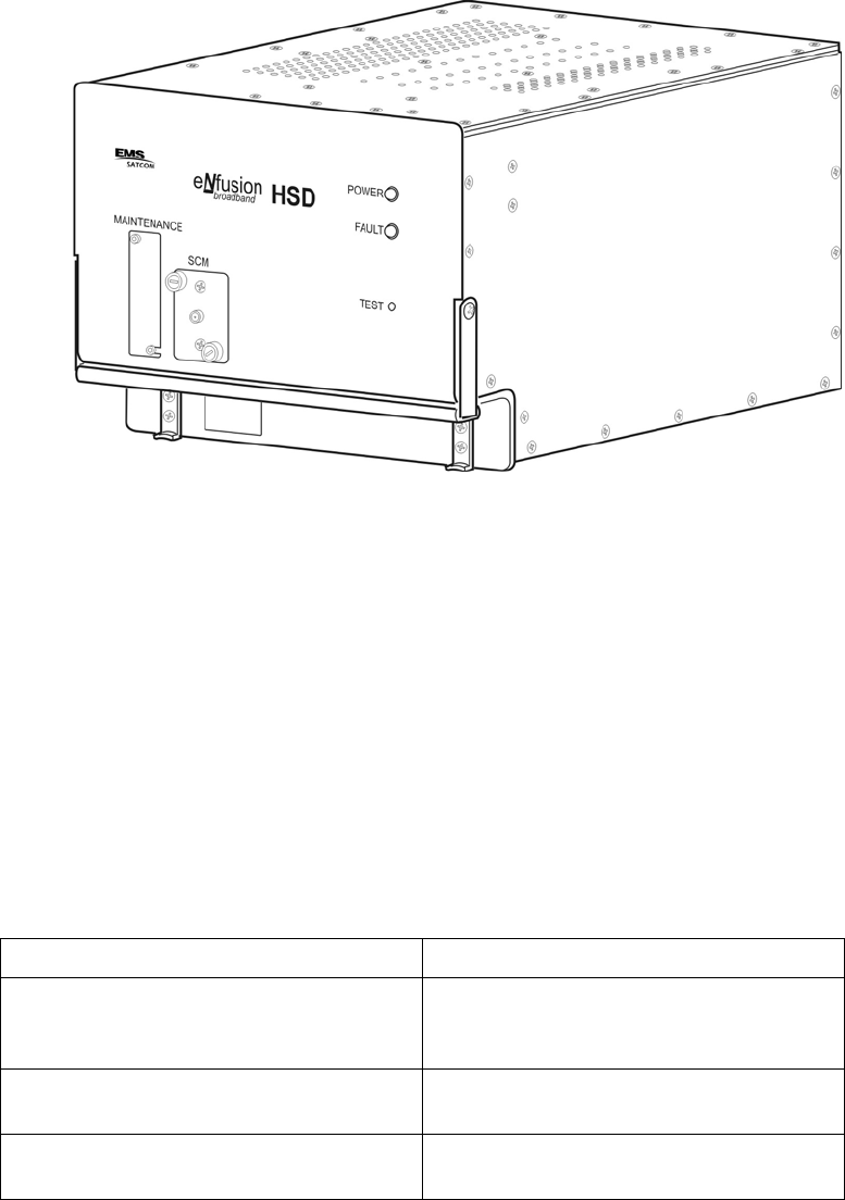
1. Illustration of Equipment
Figure INTRO-1 HSD-440 Terminal
2. Product Terms and Conditions
As stipulated in the Terms and Conditions of Sale, which accompanied the Product, EMS
SATCOM shall not at any time be liable for the activation, continuation, or cancellation of
satellite airtime services relating to the Product nor be responsible for any Product-related
airtime or network charges, however incurred. In the event EMS SATCOM is charged network
or airtime fees relating to the customer’s use of the Product, the customer shall immediately
upon notification by EMS SATCOM reimburse EMS SATCOM in full for such charges.
3. Reference Documents
Table INTRO-1 EMS SATCOM Reference Documents
Document Title EMS SATCOM Publication Number
Guidance for Aircraft Electrical Power
Utilization and Transient Protection ARINC 741. ARINC Report 413A—
Attachment 3-2, Wire Shielding and
Grounding Requirements and Appendix 7
eNfusion™ HSD-440 High-speed Data
Terminal Pilot’s Guide MN-1252-33138
eNfusion™ HSD High-speed Data Terminal
Developer’s Guide MN-1252-13005
EMS SATCOM
SYSTEM DESCRIPTION, INSTALLATION, AND MAINTENANCE MANUAL
eNfusion™ HSD-440 High-speed Data Terminal
23-15-30 INTRO-3
24 JUN 09
4. Acronyms and Abbreviations
The following acronyms and abbreviations are used in this document.
AC Access Concentrator
ACP Audio Control Panel
ACSE Access Control and Signalling Equipment
ACU Antenna Control Unit (also known as BSU or Driver)
AERO Aeronautical
AES Aircraft Earth Station
AMBE Advanced Multi-Band Excitement
AORE Atlantic Ocean Region-East
AORW Atlantic Ocean Region-West
APN Access Point Name
ATC Air Traffic Control
AWG American Wire Gauge
BGAN Broadband Global Area Network
BITE Built-In Test Equipment
BOP Bit Oriented Protocol
bps Bits per second
BRI Basic Rate ISDN
BSU Beam Steering Unit (also known as ACU or Driver)
C/No Carrier-to-Noise
CCW Counter Clockwise
CFDS Centralized Fault Display System
CMU Communications Management Unit
CRC Cyclic Redundancy Check
CW Clockwise
DITS Digital Information Transfer System
DLNA Diplexer/Low-Noise Amplifier
DSL Digital Subscriber Line
EIRP Effect Isotropic Radiated Power
EMI Electromagnetic Interference
ESD Electrostatic Discharge
EST Eastern Standard Time
FAA Federal Aviation Authority
FET Field-Effect Transistor
23-15-30 INTRO-4
24 JUN 09
EMS SATCOM
SYSTEM DESCRIPTION, INSTALLATION, AND MAINTENANCE MANUAL
eNfusion™ HSD-440 High-speed Data Terminal
FMS Flight Management System
FRLP Forward Link Pairs
FWD ID Forward ID
GES Ground Earth Station
GND Ground
HGA High-gain Antenna
HPA High Power Amplifier
HTML Hyper Text Markup Language
Hz Hertz
I/O Input/Output
ICAO International Civil Aviation Organization
ICD Interconnection Drawing
IMN Inmarsat Mobile Number
INS Inertial Navigational System
IOR Indian Ocean Region
IRS Inertial Reference System
ISDN Integrated Services Digital Network
ISN Inmarsat Serial Number
ISP Inmarsat Service Providers
ISP Internet Service Provider
JAA Joint Aviation Authorities
kbps Kilobits per Second
LAN Local Area Network
LES Land Earth Station
LRU Line Replaceable Unit
LS line select
LSB Least Significant Bit
MA Mechanical Steered Antenna
Mbps Megabit per second
MCDU Multipurpose Control Display Unit
MCU Modular Concept Unit
MES Mobile Earth Station
MPDS Mobile Packet Data Services
MPU Maintenance Port Utility
ms Millisecond
EMS SATCOM
SYSTEM DESCRIPTION, INSTALLATION, AND MAINTENANCE MANUAL
eNfusion™ HSD-440 High-speed Data Terminal
23-15-30 INTRO-5
24 JUN 09
MSB Most Significant Bit
MSN Mobile Serial Number
MSN Multiple Subscriber Number
NAT Network Address Translation
NO normally open
NT Network Terminator
O&I Outline and Installation Diagram
OA Other Antenna
OCXO Oven Controlled Crystal Oscillator
OEM Original Equipment Manufacturer
ORR Ocean Region Registration
ORT Owner Requirements Table
PAST Person Activated Self Test
PC Personal Computer (or laptop)
PN Part Number
POR Pacific Ocean Region
POST Power On Self Test
POTS Plain Old Telephone System
PPP Point-to-Point Protocol
PPPoE Point-to-Point Protocol over Ethernet
PSTN Public Switch Telephone Network
PTT Push-to-Talk
RAM Random Access Memory
REA Responsible Engineering Authority
RF Radio Frequency
RFI Radio Frequency Interference
RFU Radio Frequency Unit
rms root mean square
ROM Read-only Memory
RTN Return
Rx Receive
S/T (ISDN) Key interfaces of an ISDN network are known as Reference Points. Reference
Point T is on the user’s side of the network and allows a single TE/TA to be
connected. Reference Point S is on the user’s side of the network and allows
multiple TEs/TAs to be connected. Electrically, point T and point S are the same
point.

23-15-30 INTRO-6
24 JUN 09
EMS SATCOM
SYSTEM DESCRIPTION, INSTALLATION, AND MAINTENANCE MANUAL
eNfusion™ HSD-440 High-speed Data Terminal
SBB SwiftBroadband
SCM Software Configuration Module
SCPC Single Channel per Carrier
SDI Source/Destination Identification
SDU Satellite Data Unit
SNAC Single Network Access Code
SPID Service Profile Identifier
STBD Starboard
STE Secure Terminal Equipment
STU Secure Telephone Unit
TA Terminal Adapter
TE Terminal Equipment
Tx Transmit
USIM Universal Subscriber Identity Module
VHF very high frequency
VSWR Voltage Standing Wave Ratio
WOW Weight on Wheels
5. Safety Advisories
Warnings, cautions, and notes in this manual provide the reader with the following information:
• A WARNING describes an operation, procedure, or condition that, if not obeyed, could
cause injury or death.
• A CAUTION describes an operation, procedure, or condition that, if not obeyed, could
cause damage to the equipment.
• A NOTE provides supplementary information or explanatory text that makes it easier to
understand and perform procedures.
All personnel who install, operate, and maintain the HSD-440 terminal and associated test
equipment must know and obey the safety precautions listed below. The procedures provided
in this manual assume that the person performing installation or maintenance tasks is familiar
with and obeys standard aviation shop and safety practices.
The general safety advisories include the following:
WARNING: SERVICE PERSONNEL MUST OBEY STANDARD SAFETY
PRECAUTIONS, SUCH AS WEARING SAFETY GLASSES, TO PREVENT
PERSONAL INJURY WHILE INSTALLING OR PERFORMING SERVICE
ON THIS TERMINAL.

EMS SATCOM
SYSTEM DESCRIPTION, INSTALLATION, AND MAINTENANCE MANUAL
eNfusion™ HSD-440 High-speed Data Terminal
23-15-30 INTRO-7
24 JUN 09
WARNING: ASSOCIATED SATELLITE COMMUNICATIONS EQUIPMENT RADIATES
HIGH FREQUENCY RADIATION AND POSES A RADIATION HAZARD
OF 1.6 GHZ. SERVICE PERSONNEL MUST EXERCISE CARE TO KEEP
CLEAR OF THE ANTENNA'S BEAM WHILE PERFORMING
OPERATIONAL TESTS OR INSTALLATION VERIFICATION
PROCEDURES.
DO NOT APPROACH WITHIN 8 FEET (2.5 METRES) OF THE ANTENNA
DURING ANTENNA OPERATION (TRANSMISSION).
DURING ANTENNA OPERATION (TRANSMISSION), MAKE SURE THAT
PERSONNEL ARE EXPOSED TO A MINIMUM OF ANY REFLECTED,
SCATTERED, OR DIRECT BEAMS.
WARNING: TURN OFF POWER BEFORE DISCONNECTING ANY TERMINAL FROM
WIRING. DISCONNECTING THE TERMINAL WITHOUT TURNING
POWER OFF MAY CAUSE VOLTAGE TRANSIENTS THAT CAN DAMAGE
THE TERMINAL.
CAUTION: THIS EQUIPMENT INCLUDES ITEMS THAT ARE ELECTROSTATIC
DISCHARGE SENSITIVE (ESDS) DEVICES. ESDS DEVICES ARE
SUBJECT TO DAMAGE BY EXCESSIVE LEVELS OF VOLTAGE AND/OR
CURRENT. THE LOW-ENERGY SOURCE THAT MOST COMMONLY
DESTROYS ESDS DEVICES IS THE HUMAN BODY, WHICH, IN
CONJUNCTION WITH NONCONDUCTIVE GARMENTS AND FLOOR
COVERINGS, GENERATES AND RETAINS STATIC ELECTRICITY. TO
ADEQUATELY PROTECT ESDS DEVICES, THE DEVICE AND
EVERYTHING THAT CONTACTS IT MUST BE BROUGHT TO GROUND
POTENTIAL BY PROVIDING A CONDUCTIVE SURFACE AND
DISCHARGE PATHS. USE STANDARD INDUSTRY PRECAUTIONS TO
KEEP RISK OF DAMAGE TO A MINIMUM WHEN TOUCHING,
REMOVING, OR SERVICING THE EQUIPMENT.
23-15-30 INTRO-8
24 JUN 09
EMS SATCOM
SYSTEM DESCRIPTION, INSTALLATION, AND MAINTENANCE MANUAL
eNfusion™ HSD-440 High-speed Data Terminal
Blank Page
EMS SATCOM
SYSTEM DESCRIPTION, INSTALLATION, AND MAINTENANCE MANUAL
eNfusion™ HSD-440 High-speed Data Terminal
23-15-30 1-1
24 JUN 09
SYSTEM DESCRIPTION
This section includes basic information about the HSD-440 terminal, including the following
sections:
•Inmarsat System Overview
•Equipment Overview
•Equipment Specifications
•Software Description
•Mechanical Description
•Electrical DescriptionUser Interfaces
•Initiated Self-Test
•Modes of Operation
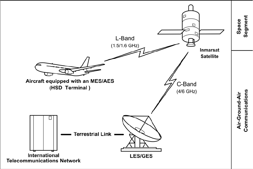
1. Inmarsat System Overview
The satellite communication system includes global satellite networks, Land Earth Stations
(LESs), Ground Earth Stations (GESs), Aircraft Earth Stations (AESs), and Mobile Earth
Stations (MESs).
The LES/GES is the part of the satellite communication system that is on the ground. These
numerous, international stations are responsible for routing voice and data calls to/from the
MES/AES to/from their destinations around the world.
The MES/AES is the part of the satellite communication system that is on the aircraft. This
station includes the following components:
• HSD-440 terminal
• Antenna subsystem
• Cabin communications system
• Analog connected telephones
• Cockpit voice system
• Other aircraft avionics
Figure 1-1 illustrates a simplified satellite communications system.
23-15-30 1-2
24 JUN 09
EMS SATCOM
SYSTEM DESCRIPTION, INSTALLATION, AND MAINTENANCE MANUAL
eNfusion™ HSD-440 High-speed Data Terminal
Figure 1-1 Simplified Aeronautical Satellite Communications System
Satellite communication systems provide users with long-range voice and data communication
by accessing global satellite and ground communications networks.
Inmarsat is an international organization that operates and maintains multiple geostationary
satellites and satellite networks. The satellites that provide Swift64 services are called I-3
satellites. Each satellite is located over an Ocean Region (OR); the current OR names are:
• Atlantic Ocean Region-East (AOR-E)
• Atlantic Ocean Region-West (AOR-W)
• Indian Ocean Region (IOR)
• Pacific Ocean Region (POR)
These satellites provide worldwide telecommunication services for aviation, shipping, and
land-mobile terminal users. The satellites connect to ground telecommunication systems
through the LES/GES. The LES converts the space segment of the communication link to a
format compatible with public and private telephone and data networks. Each satellite is
associated with a number of LESs that fall within its coverage.
The satellites that provide SBB services are called I-4 satellites. At the time of publishing,
three I-4 satellites are operating: Americas, EMEA. and Asia-Pacific.
The HSD-440 terminal, in conjunction with an ARINC 741/781 High-gain Antenna (HGA), acts
as an MES/AES. The combined system provides users with a data and voice communications
link to the satellite network and global telecommunications system.
EMS SATCOM
SYSTEM DESCRIPTION, INSTALLATION, AND MAINTENANCE MANUAL
eNfusion™ HSD-440 High-speed Data Terminal
23-15-30 1-3
24 JUN 09
2. Equipment Overview
The HSD-440 terminal is a scalable, high-speed data, satellite communications terminal that
provides world-wide voice and data services to aircraft through a high-speed communication
link with the Inmarsat Satellite Network. The HSD-440 terminal interfaces with ARINC
741-compatible antenna subsystems to communicate with the space segment of the Inmarsat
Satellite Network via L-band RF signals.
The HSD-440 terminal communicates with various avionics equipment, such as the aircraft’s
IRS and CMU, in order to coordinate and access a wide range of services. The HSD-440
terminal also communicates with cabin and cockpit voice and data equipment to provide
phone, fax, internet connection, and other services on board the aircraft.
The HSD-440 terminal also provides access to the CMU short message system. The HSD-440
terminal ensures that high-priority safety and flight-operation communication is not blocked
or delayed by other types of low-priority transmissions.
HSD-440 terminals contain the following:
• Two (2) channel cards
• Data input/output (I/O) card
• Control processor
• High Power Amplifier (HPA)
• Universal (110 V ac 400 Hz / 28 V dc) power supply
The HSD-440 terminal operates with a high-gain antenna subsystem to provide
circuit-switched (Swift64 Mobile ISDN), packet-switched (Swift64 MPDS) services, 1 PRT
channel, 1 C channel, 2 Swift64 channels, and SBB over the Inmarsat satellite
communications network.
HSD-440 terminals support the following services and functions:
• Inmarsat Integrated Services Digital Network (ISDN) Single Channel Per Carrier (SCPC)
Service
• Inmarsat Serial Mobile Packet Data Services (MPDS)
• Inmarsat Aero P, R, T channel data
• Inmarsat Aero C channel H+ voice
• SwiftBroadband (SBB) service
• Cockpit communications for ground-to-air and air-to-ground calls using the MCDU
The HSD-440 terminal is a high-speed data terminal that contains two channel cards, a high
stability reference oscillator, a high power amplifier, a data processor module, and a power
supply. The HSD-440 terminal receives power from the aircraft as either 28 V dc or 115 V ac,
400 Hz.
The HSD-440 terminal supports one channel of Inmarsat Swift64 MPDS or two channels of
Mobile ISDN 64 kbps data links, and one SBB channel. To use the SBB service, the HSD-440
terminal obtains subscriber information from a SIM card installed in the SCM. The SCM slot
is located on the front of the HSD-440 terminal next to the maintenance connector.

23-15-30 1-4
24 JUN 09
EMS SATCOM
SYSTEM DESCRIPTION, INSTALLATION, AND MAINTENANCE MANUAL
eNfusion™ HSD-440 High-speed Data Terminal
The HSD-440 terminal has three ports that support the following interfaces: EURO ISDN S/T,
Ethernet (10BASE-T), and POTS. Although able to support multiple configurations depending
on user needs, the following constraints apply:
• EURO ISDN S/T port supports Swift64 Mobile ISDN (circuit-switched) only
• 10BASE-T port supports SBB, Swift64 Mobile ISDN, or MPDS
• POTS port supports ISDN (speech) or 3.1 kHz audio (fax)
NOTE: Only one service type can be used at one time on an HSD-440 terminal channel card.
The first channel card can support one channel of MPDS, two channels of Swift64
service, or one channel of SwiftBroadband. The second channel card supports a single
Classic Aero service (Aero-H/H++).
The most likely configurations include connecting a networking device such as a router or a
file server to allow multiple users to share the channel(s) provided by the HSD-440 terminal.
3. Equipment Specifications
Table 1-1 lists the physical characteristics and equipment specifications for the HSD-440
terminal.
Table 1-1 HSD-440 TE Characteristics and Specifications
Characteristic Specification
Certification/related documents
ARINC characteristics 600-12, Air Transport Avionics Equipment
Interfaces, December 12, 1998
Appendix 10 of the ARINC 704-7
RTCA documents RTCA/DO-160E, Environmental Conditions and
Test Procedures for Airborne Equipment,
July 29, 1997
HSD-440 Terminal Software RTCA/DO-178B Level D
Physical Size
Height 19.41 cm (7.64 in)
Width 25.91 cm (10.20 in)
Length 36.45 cm (14.58 in)
Weight 15.75 kg (34.7 lbs)
Mounting information 8-MCU Tray (per ARINC 600, 8-MCU LRU)
Maintenance requirements No scheduled maintenance is required
Electrical specifications
HSD-440 terminal AC input power
Voltage Minimum: 100 V rms
Typical: 115 V rms
Maximum: 122 V rms

EMS SATCOM
SYSTEM DESCRIPTION, INSTALLATION, AND MAINTENANCE MANUAL
eNfusion™ HSD-440 High-speed Data Terminal
23-15-30 1-5
24 JUN 09
Power consumption Maximum: 460 W
NOTE: Of this power consumption, 400 W is
dissipated internally and 60 W of RF power
is dissipated externally.
Frequency Minimum: 300 Hz
Typical: 400 Hz
Maximum: 800 Hz
Frequency band Tx: 1626.5 to 1660.5 MHz
Rx: 1525.0 to 1559.0 MHz
HSD-440 terminal DC input power
Voltage Minimum: 22 V dc
Typical: 28 V dc
Maximum: 30.3 V dc
Power consumption Maximum: 460 W
NOTE: Of this power consumption, 400 W is
dissipated internally and 60 W of RF power
is dissipated externally.
Power requirements
AC 115 V ac, 400 Hz nominal, @ 4 A (460 W maximum)
DC + 28 V dc @ 15.5 A (460 W maximum)
Wire gauge DC power: 12 AWG
AC power: 20 AWG (hot lead), 12 AWG (cold lead)
Signals: Unless otherwise specified, use 22 AWG
for all signal wires
Ground requirements ARINC 741
Circuit breakers Install circuit breakers according to the maintenance
requirements of the aircraft.
Heating and cooling requirements
Cooling air ARINC 600
Flow rate 88 kg/hr (194 lbs/hr)
Pressure drop 5 ± 3 mm (0.20 ± 0.12 in.) of H2O
Receive input impedance 50 ohms
Transmit output impedance 50 ohms
VSWR 2:1 maximum
External interfaces
External parameters
Antenna gain Minimum: 8 dB
Maximum: 17 dB
Table 1-1 HSD-440 TE Characteristics and Specifications (Continued)
Characteristic Specification

23-15-30 1-6
24 JUN 09
EMS SATCOM
SYSTEM DESCRIPTION, INSTALLATION, AND MAINTENANCE MANUAL
eNfusion™ HSD-440 High-speed Data Terminal
Table 1-2 lists the RTCA/DO-160E environmental characteristics for the HSD-440
terminal.
Antenna to DLNA loss Maximum: 0.3 dB
DLNA gain Minimum: 53 dB
Maximum: 60 dB
DLNA noise Maximum: 1.8 dB
DLNA to HSD-440 terminal
total Rx total loss Minimum: 6 dB
Maximum: 25 dB
HSD-440 terminal to
antenna total Tx cable loss
including DLNA insertion
loss
Minimum: 1 dB
Maximum: 2.5 dB
DLNA insertion loss Maximum: 0.8 dB
External digital interfaces
Control interface ARINC 429 high-speed (100 kbps) data bus
RS-232 maintenance
interface (rear and front
connector)
19 200 kbps, N81, None
Ethernet user interface (2) 10BASE-T input and output for SBB, SCPC (Swift64
Mobile ISDN) and MPDS using Point-to-Point
Protocol over Ethernet (PPPoE)
ISDN ISDN S/T physical interface supporting up to seven
external connections to Terminal Adapter (TA) or
Terminal Equipment (TE) devices
POTS tip/ring interface (2) Plain Old Telephone System (POTS) analog
interface
Table 1-2 HSD-440 Terminal RTCA/DO-160E Environmental Characteristics
Section Environmental Condition Category
4.0 Temperature and Altitude
4.5.1 Ground Survival Low F2
4.5.1 Short Time Operating Low F2
4.5.2 Operating Low Temperature F2
4.5.3 Ground Survival High Temperature F2
4.5.3 Short Term Operating High Temperature F2
4.5.4 Operating High Temperature F2
4.5.5 In Flight Loss of Cooling Z
4.6.1 Altitude Test F2
Table 1-1 HSD-440 TE Characteristics and Specifications (Continued)
Characteristic Specification

EMS SATCOM
SYSTEM DESCRIPTION, INSTALLATION, AND MAINTENANCE MANUAL
eNfusion™ HSD-440 High-speed Data Terminal
23-15-30 1-7
24 JUN 09
4.6.2 Decompression Test A2
4.6.3 Over Pressure Test A2 (modified)
5.3.1 Temperature Variation B
6.3.2 Humidity B (modified)
7.0 Operational Shock and Crash Safety B
7.2.1 Operational Shock B
7.3 Crash Safety Impulse B
7.3.2 Crash Safety Sustained B
8.0 Vibration—Fixed Wing S (CURVE B)
8.4 Vibration—Heli U (CURVE G)
9.7.2 Explosive Atmosphere E (modified)
10.0 Waterproofness X
11.0 Fluids Susceptibility X
12.4
12.5
Sand and Dust X
13.0 Fungus Resistance F
14.3.6 Salt Fog S
15.3 Magnetic Effect Z
16.0 Power Input
16.6.1.1 DC Input BZ
16.6.1.1 Emergency Operation BZ
16.6.1.2 Ripple Voltage BZ
16.6.1.3 Momentary Power Interruptions BZ
16.6.1.4 Normal Surge Voltage BZ
16.6.1.5 Engine Starting Under voltage Operation BZ
16.6.2.1 Abnormal Voltage Steady State BZ
16.6.2.3 Momentary Under Voltage Operation BZ
16.6.2.4 Abnormal Surge Voltage BZ
16.5.1.1 AC Input A(WF)H
16.5.1.2 Voltage Modulation A(WF)H
16.5.1.3 Frequency Modulation A(WF)H
16.5.1.4 Momentary Power Interruptions A(WF)H
16.5.1.5 Normal Surge Voltage A(WF)H
16.5.1.6 Normal Frequency Variations A(WF)H
16.5.1.7 Voltage DC Content A(WF)H
16.5.1.8 Harmonic Distortion A(WF)H
Table 1-2 HSD-440 Terminal RTCA/DO-160E Environmental Characteristics
(Continued)
Section Environmental Condition Category

23-15-30 1-8
24 JUN 09
EMS SATCOM
SYSTEM DESCRIPTION, INSTALLATION, AND MAINTENANCE MANUAL
eNfusion™ HSD-440 High-speed Data Terminal
4. Software Description
This section describes the software specifications and operational software components of
HSD-440 terminals.
A. Software Specifications
The software meets the following DO-178B standards:
• Swift64 to Level D
• Classic Aero voice and data to Level D
• SwiftBroadband to Level E
B. Operational Software Part Numbers
Table 1-3 provides a list of software part numbers for the HSD-440 terminal.
16.5.2.1 Abnormal Operating Conditions A(WF)H
16.5.2.2 Momentary Under Voltage Operation A(WF)H
16.5.2.3 Abnormal Surge Voltage A(WF)H
17.4 Voltage Spike A
18.0 Audio Frequency Conducted Susceptibility [K(WF)Z]
19.3 Induced Signal Susceptibility ZW
20.0 Radio Frequency Susceptibility
Conducted Susceptibility R
Radiated Susceptibility R
21.0 Emission of RF Energy
Conducted (Power Lines) B
Conducted RF Emission B
Radiated RF Emission B
22.0 Lightning Induced Transient Susceptibility A3J33
(modified)
23.0 Lightning Direct Effects X
24.0 Icing X
25.0 Electrostatic Discharge (ESD) A (modified)
26.0 Fire Flammability C
Table 1-2 HSD-440 Terminal RTCA/DO-160E Environmental Characteristics
(Continued)
Section Environmental Condition Category

EMS SATCOM
SYSTEM DESCRIPTION, INSTALLATION, AND MAINTENANCE MANUAL
eNfusion™ HSD-440 High-speed Data Terminal
23-15-30 1-9
24 JUN 09
5. Mechanical Description
The HSD-440 terminal is an 8-MCU sized unit with mounting requirements according to the
ARINC 600 specification. The front panel has one, socket D-Type size B (25 contacts)
maintenance port connector (under protective cover) for data loading and monitoring of the
terminal. Two front-panel LEDs indicate terminal status.
The rear connector complies with ARINC 600, shell size 2 and has three inserts: upper, middle,
and bottom. The upper and middle inserts each have one #1 coaxial contact and seventy,
22-gauge signal contacts. The bottom insert connector has contact with only positions 1, 2,
3, 7, 8, 12, and 13. The rear panel has three polarization points.
Figure 3-7 through Figure 3-10 present the Outline and Installation diagrams for the HSD-440
terminal. For detailed wiring information, refer to the Interconnection and Contact Assignment
drawings presented in "Installation" on page 3-1 and shown in Table 1-4.
6. Electrical Description
"Installation" on page 3-1 describes all ARNC 600 connector contact assignments and physical
details, including part numbers, insert descriptions, and polarization keying.
The loading/gradient specifications for all HSD-440 terminal installations are provided in table
format in "Installation" on page 3-1. These tables list all of the ARINC top, middle, and bottom
plug pin designations and provide installation connection details.
Table 1-3 HSD-440 Terminal Operational Software
EMS SATCOM Part
Number* Description
LI-1252-33222
L1-1252-33374
HSD-440 (1252-A-3420-02) Software Control Document
HSD-440 (1252-A-3420-03) Software Control Document
1252-SW-3305 HSD-440 Terminal data I/O software
1252-SW-3315 Control processor software
1210-A-0039 CC 1
1210-A-0038-03 CC 1
1210-A-0039 CC 2
1210-A-0038 CC 2
Aero SBB channel card software
* Software levels are not available.
Table 1-4 HSD-440 Terminal Installation Drawing Reference Matrix
Models Figures
ALL Outline and Installation diagrams: Figure 3-7 through Figure 3-10
System Interconnect: Figure 3-11
23-15-30 1-10
24 JUN 09
EMS SATCOM
SYSTEM DESCRIPTION, INSTALLATION, AND MAINTENANCE MANUAL
eNfusion™ HSD-440 High-speed Data Terminal
The HSD-440 terminal contains a communications switch that supports Inmarsat Swift64
Mobile ISDN and MPDS service within an 8-MCU assembly built in accordance to ARINC 600
specifications.
The HSD-440 terminal uses the ARINC 429 multi-control bus to interface with the ACU/BSU
to control the RF antenna and obtain antenna-subsystem status information over the Built-in
Test Equipment (BITE) lines. The HSD-440 terminal receives the required navigational data,
provided by the aircraft Inertial Navigational System (INS), via the ARINC 429 IRS bus. The
aircraft supplies either 28 V dc or 115 V ac 400 Hz power to the HSD-440 terminal.
The HSD-440 terminal also uses an ARINC 429 bus to interface with the Communications
Management Unit (CMU) and the Multipurpose Control Display Unit (MCDU).
Detailed pin and connector descriptions for HSD-440 terminals are provided for all supported
installation modes and configurations in "Installation" on page 3-1.
7. System Interfaces
This section briefly describes the external HSD-440 terminal system interfaces, as shown in
Figure 1-2, required to control, monitor, maintain, and supplement the terminal. "Installation"
on page 3-1 provides a detailed description of interface connections.
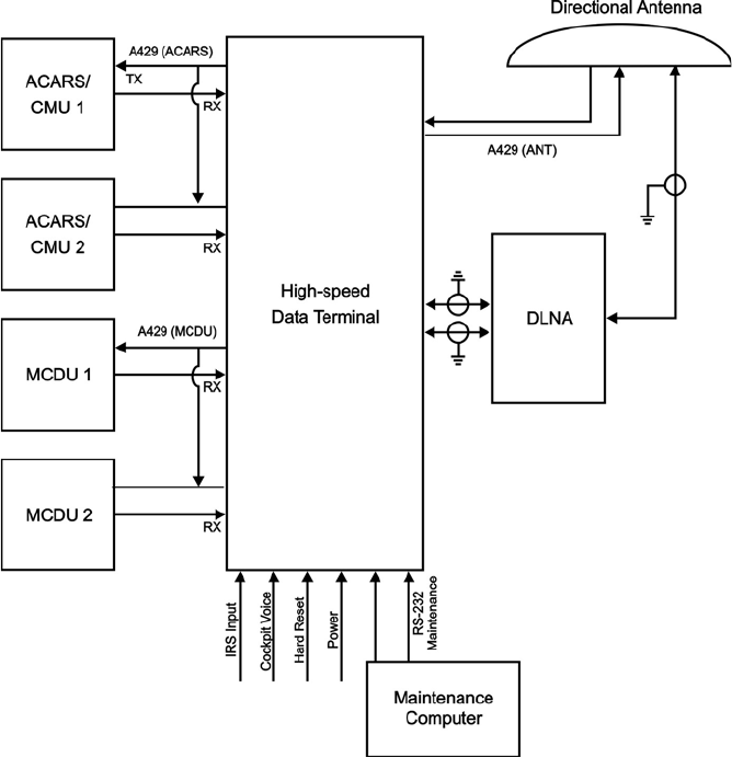
EMS SATCOM
SYSTEM DESCRIPTION, INSTALLATION, AND MAINTENANCE MANUAL
eNfusion™ HSD-440 High-speed Data Terminal
23-15-30 1-11
24 JUN 09
Figure 1-2 HSD-440 Terminal Interfaces
A. Source Destination Identification (SDI)
The SDI is provided to the HPA as per ARINC 741 specifications.
B. ICAO IDs and Forward IDs
The ICAO ID is a 24Bit address that identifies the AES on the network much like a FWD
ID. Each aircraft has a single unique ICAO ID.
The HSD-440 terminal uses two 24-bit IDs called Forward Link Pairs (FRLPs) for the
Swift64 service, which include a Forward ID (FWD ID). The HSD-440 terminal reads the
first channel FWD ID from the EEPROM and performs a look-up for the second channel
FWD ID.
The ISN consists of the type approval number and the FWD ID address. Each FWD ID is
associated with Inmarsat Mobile Numbers (IMNs), which are the numbers that a user dials
from the ground to reach a terminal on an aircraft. There is a unique IMN for each of the
service types (e.g., data or voice).

23-15-30 1-12
24 JUN 09
EMS SATCOM
SYSTEM DESCRIPTION, INSTALLATION, AND MAINTENANCE MANUAL
eNfusion™ HSD-440 High-speed Data Terminal
C. Weight-On-Wheel (WOW) Pin Wiring
WOW discretes indicate when an aircraft is on the ground and are used for flight
data-logging purposes. These discretes are not required on the typical installation, as
equivalent data indicating the aircraft is airborne is available (for example, true track and
groundspeed IRS information) and supplied to the HSD-440 terminal. Note 40 of ARINC
741 specification documentation defines the requirement for WOW data.
D. IRS ARINC 429 Interface
Table 1-5 shows the IRS ARINC 429 bus labels and associated data types. For more
details on characteristics, refer to Appendix 10 of the ARINC 704-7, Inertial Reference
System document.
In Stand-Alone installations, the HSD-440 terminal requires high-speed, ARINC 429, IRS
Navigational information (as shown in Table 1-5) to compute the azimuth/elevation for
antenna pointing and aircraft attitude information for Doppler correction.
E. Antenna Interface
In Stand-Alone Mode installations, the HSD-440 terminal interfaces to any
mechanically-steered, conformal-array, or phased-array antenna subsystems compatible
with ARINC 741 or 781. The antenna-steering commands and status messages are
communicated between the HSD-440 terminal and antenna subsystem over ARINC 429,
multi-control, Top/Port and/or Starboard BITE and HPA mute buses, as defined in ARINC
741, Part 1.
F. Owner’s Requirements Table (ORT)
The ORT preserves information relevant to the operation and configuration of the
HSD-440 terminal when the terminal is shut down.
Table 1-5 ARINC 429 IRS Navigational Requirements
Label (Octal) Name Interval Rate
Min (ms) Max (ms)
310 Latitude 100 200
311 Longitude 100 200
312 Ground speed 25 50
313 True track 25 50
314 True heading 25 50
324 Pitch angle 10 20
325 Roll angle 10 20
361 Altitude 20 40

EMS SATCOM
SYSTEM DESCRIPTION, INSTALLATION, AND MAINTENANCE MANUAL
eNfusion™ HSD-440 High-speed Data Terminal
23-15-30 1-13
24 JUN 09
G. CMU
Each HSD-440 terminal can be connected to up to two CMUs. The CMUs operate in two
modes: it can select from a number of Satellite Service Providers rather than Inmarsat
only, or it can operate with no preferred Satellite Service Provider.
The HSD-440 terminal exchanges information with the CMU over ARINC 429 interfaces.
The default speed is low, but you can set the speed of the buses to high in the ORT.
H. MCDU
The MCDU is an interface display that lets you communicate with systems on an aircraft,
including CMU and the HSD-440 terminal.
At power up, the HSD-440 terminal broadcasts its subsystem identifier word, with label
172 and subsystem SAL 307, approximately once per second. The MCDU finds this label
and sends an ENQ (enquiry) word to request menu text. This exchange proceeds, as per
ARINC 739 requirements, to transfer data between the MCDU and the HSD-440 terminal.
Once active communication has been established between the units and the menu text
has been loaded to the MCDU, the HSD-440 terminal continues scanning its ARINC 429
receiving port for activity from the MCDU. The MCDU transfers information to the HSD-440
terminal one character at a time.
Users can make air-to-ground voice calls with the MCDU. Incoming calls are announced
by a combination of lights or chimes according to the way in which the terminal is strapped.
I. Antenna Subsystem RF Interface
The system RF parameters, such as cable losses and antenna gain, are delimited to make
sure that the HSD-440 terminal performance requirements are met. Refer to "Installation"
on page 3-1 for a definition of these parameters and their expected values.
J. Remote Status Panel (Optional)
The outputs to the optional remote status panel provide a visual indication of the
operational status of the HSD-440 terminal; they mirror the front panel LEDs labeled as
Power (LED1) and Fault (LED2), as defined in Table 1-6. Refer to "Installation" on page
3-1 for detailed installation and circuit requirements.
Table 1-6 HSD-440 Terminal LED Output Designations
LED Signal Label LED Color Indication Description
LED1 Power
On Green Power On: HSD-440 terminal supply voltage is
active. Flashes at 1 Hz when the HPA is
transmitting
LED2 Fault Red Fault: Fault condition as described in "Fault
Conditions" on page 1-14
23-15-30 1-14
24 JUN 09
EMS SATCOM
SYSTEM DESCRIPTION, INSTALLATION, AND MAINTENANCE MANUAL
eNfusion™ HSD-440 High-speed Data Terminal
K. Fault Conditions
A failure in the HSD-440 terminal may be due to a number of fault conditions. Upon
detection of a fault condition, the HSD-440 terminal activates its red, Fault LED. The
potential fault conditions are as follows:
• Channel card fault
• HPA fault
• Internal ROM fault
• Internal RAM fault
• Over temperature fault
L. Remote Reset
The remote reset output provides an external reset function for the complete HSD-440
terminal. Pressing the momentary normally open (NO) switch resets the system's
processor-card circuitry.
The remote reset has the same function as pressing the test button on the front panel of
the terminal.
8. User Interfaces
The HSD-440 terminal can support multiple voice and data communication configurations.
The most likely user configurations include a networking device such as a router that allows
multiple users to optimize and share the channel capability offered by the HSD-440 terminal.
The networking device must be able to decide which combination of services is required at
any particular moment and activate it accordingly. Therefore, simultaneous Ethernet and ISDN
connections are required.
A different way to achieve this effect is for one of the Ethernet ports to carry a PPPoE virtual
connection between the networking device (typically a router) and the HSD-440 terminal.
Support for PPPoE is also required on the user's side. HSD-440 terminals support two Ethernet
interfaces. Ethernet can provide SBB, SCPC, or MPDS services; whereas, ISDN (BRI-ST) is
only capable of SCPC service.
Voice and fax devices are supported by direct connection to the HSD-440 terminal via EURO
ISDN telephones and fax machines or by indirect connection to a router or TA. Two-wire
telephone handsets or voice devices (PBXs) may be directly connected to the POTS ports.
HSD-440 terminals support two Swift64 Mobile ISDN voice or SCPC data services, one
instance of MPDS over Ethernet (PPPoE), or a single SBB connection.
A. ISDN Circuit-Switched Data Interface
HSD-440 terminals connect to a variety of interface options. The physical interface for
ISDN service is EURO S/T, which supports several types of connections to user
equipment.
HSD-440 terminals provide one ISDN S/T bus interface, which is capable of hosting up
to seven external physical connections to EURO ISDN devices.
EMS SATCOM
SYSTEM DESCRIPTION, INSTALLATION, AND MAINTENANCE MANUAL
eNfusion™ HSD-440 High-speed Data Terminal
23-15-30 1-15
24 JUN 09
The Swift64 channel card supports communications with two, 64 kbps, ISDN B channels
on the ISDN interface. If the channels are busy or in-call, the request for service is denied.
Several ISDN interface options are shown in Figure 1-3. In the illustrated example, the
ISDN port is used for circuit-switched services (Swift64 Mobile ISDN) or SBB voice.
NOTE: Activating an MPDS session temporarily disables the ISDN port while MPDS
service is in-use.
For connection to Inmarsat Mobile ISDN services, install an RJ45 interface connector in
the cabin area. "Installation" on page 3-1 describes the RJ45 connector and cable
termination.
Figure 1-3 ISDN Connection Options
B. Ethernet Data Interfaces
HSD-440 terminals provide two Ethernet data interfaces.
Each Ethernet port provides a 10 Mbps access, with a 10BASE-T physical interface. The
HSD-440 terminal data I/O controller takes the PPP data stream and directs it to the
required port on the channel card, depending on the type of service selected by the user.
PPPoE is required on the user equipment to allow the establishment of virtual connections
to either service. You can use the Ethernet ports for either SBB, Swift64 Mobile ISDN, or
MPDS service.

23-15-30 1-16
24 JUN 09
EMS SATCOM
SYSTEM DESCRIPTION, INSTALLATION, AND MAINTENANCE MANUAL
eNfusion™ HSD-440 High-speed Data Terminal
C. ISDN S/T Interface
HSD-440 terminals provide one ISDN S/T physical interface that supports up to seven
external connections to TA or TE devices.
NOTE: An HSD-440 terminal data I/O card type 4 uses one S/T bus device connection
for system use.
You can install RJ45 interface connectors in the cabin area to facilitate connection to the
ISDN interface. Refer to "Installation" on page 3-1 for a description of the RJ45 connector
and cable termination.
D. POTS Tip/Ring Interfaces
The HSD-440 terminal includes two POTS analog interfaces. The default setting for
channel 1 is 64 kbps speech (Swift64) or AMBE+2 (SBB), and the default setting for
channel 2 is 3.1 kbps audio (Swfit64 and SBB), which is appropriate for fax calls. These
settings can be changed in the data I/O settings using the MPU.
E. Maintenance Port Interface
The HSD-440 terminal is equipped with a maintenance port, located on the front panel of
the HSD-440 terminal, with remote access also available through the rear ARINC 600
connector.
NOTE: Access to maintenance functions of the HSD-440 terminal in flight is only available
through the remote access port.
The maintenance port provides the physical connection to a password-protected
Maintenance Port Utility (MPU) that provides a system interface for users or service
personnel who need to upgrade, monitor, or troubleshoot the system.
The user connects to the maintenance port either through the maintenance 25-pin socket
D-Sub (DB25) connector on the front panel of the HSD-440 terminal or through a remote
9-pin socket D-Sub (DB9) connector via the ARINC 600 connector, as described in
"Connection Requirements" on page 4-3.
The HSD-440 terminal supports two different end user access levels within the
maintenance port architecture: End User and Field Representative. End User access is
only available when the WOW straps indicate that the aircraft is on the ground.
"Terminal MPU" on page 4-2 provides a detailed description of the two levels of user
access and the menus, report selections, functions, and system diagnostic procedures of
the HSD-440 terminal MPU.
9. Initiated Self-Test
The initiated self-test occurs during the power up sequence or you depress and hold down
the TEST button on the front panel of the terminal for 100 milliseconds or more. The initiated
self-test provides the same function as the remote reset switch.
EMS SATCOM
SYSTEM DESCRIPTION, INSTALLATION, AND MAINTENANCE MANUAL
eNfusion™ HSD-440 High-speed Data Terminal
23-15-30 1-17
24 JUN 09
10. Modes of Operation
The HSD-440 terminal currently operates in Stand-Alone Mode only. In Stand-Alone Mode,
the HSD-440 terminal controls both the internal HPA and antenna.
The system supports up to two channels in multiple combinations of Swift64 ISDN and Swift64
MPDS service or one channel SBB. The maximum number of simultaneous Swift64 ISDN
service channels is two.
23-15-30 1-18
24 JUN 09
EMS SATCOM
SYSTEM DESCRIPTION, INSTALLATION, AND MAINTENANCE MANUAL
eNfusion™ HSD-440 High-speed Data Terminal
Blank Page
EMS SATCOM
SYSTEM DESCRIPTION, INSTALLATION, AND MAINTENANCE MANUAL
eNfusion™ HSD-440 High-speed Data Terminal
23-15-30 2-1
24 JUN 09
SYSTEM OPERATION
This section provides basic information on registering and operating the HSD-440 terminal,
including the following sections:
•Registering and Activating Terminals
•Configuring Terminals
•Using Terminals
1. Registering and Activating Terminals
Registering and activating an HSD-440 terminal has the following steps:
•Preparing Terminal Information
•Obtaining ICAO Addresses
•Choosing Service Providers
•Registering Terminals
A. Preparing Terminal Information
Before installing the HSD-440 terminal, obtain an ISN and identify the Swift64 terminal
type and service category.
(1) Obtaining ISNs
EMS SATCOM provides ISNs for the HSD-440 terminal based on the intended
installation configuration. The last six digits of the ISN are the Forward ID.
When requesting ISNs, please have the following information available:
• End customer name, including contact information
• Purchase order number
• Tail registration number, aircraft type, and serial number of the aircraft on which
the terminal is being installed
• Serial number of the HSD-440 terminal(s)
EMS SATCOM Product Support is available Monday to Friday from 8 am to 5 pm
(EST). On-call support is available outside business hours, Eastern Standard Time.
Contact information for EMS SATCOM:
Product Support 1.888.300.7415
Product Support direct 1.613.591.3086
Canada and USA toll-free Sales 1.800.600.9759
Outside Canada and USA 1.613.591.9064
Fax: 1.613.591.9120
Web: www.emssatcom.com

23-15-30 2-2
24 JUN 09
EMS SATCOM
SYSTEM DESCRIPTION, INSTALLATION, AND MAINTENANCE MANUAL
eNfusion™ HSD-440 High-speed Data Terminal
(2) Identifying the Service Category and Terminal Type
Register HSD-440 terminals as Category A systems.
Table 2-1and Table 2-2 list the terminal type, frequency category, and currently
supported service types for the HSD-440 terminal stand-alone mode installations.
B. Obtaining ICAO Addresses
Obtain your ICAO address from your local aeronautical authority. Your service provider
will require this address when you register.
C. Choosing Service Providers
Contact Inmarsat for an up-to-date list of Inmarsat Service Providers using the following
contact information:
Inmarsat
99 City Road, London
EC1Y 1AX
Tel: +44 20 7728 1000
Fax: +44 20 728 1044
Customer Care
Tel: +44 20 7728 1777
Fax: +44 20 7728 1142
Email: customer_care@inmarsat.com
Web address: www.inmarsat.com
Table 2-1 HSD-440 Terminal Frequency Category and Type
Service Type Inmarsat Frequency Category Terminal Type Approval
Swift64 Category A 76ES10
SBB Category A B6ES04
Table 2-2 HSD-440 Terminal Service Types
Service Type Supported Services
Classic C-channel Voice
P/R/T Data
Swift64 64 kbps Speech
3.1 kHz Audio
56 kbps Data
64 kbps UDI
MPDS
SwiftBroadband 3.1 kHz Audio
56 kbps Data
64 kbps UDI
AMBE+2
Packet-switched services: Background (up to 432
kbps), Streaming (32 kbps, 64 kbps, 128 kbps)
EMS SATCOM
SYSTEM DESCRIPTION, INSTALLATION, AND MAINTENANCE MANUAL
eNfusion™ HSD-440 High-speed Data Terminal
23-15-30 2-3
24 JUN 09
D. Registering Terminals
Contact your Inmarsat service provider and ask for a Registration for service activation
of Aircraft Earth Station form. With this form, you can register for both Swift64 services
and Aero H+ services. Both of these activations are required for the terminal to operate.
The services available depend on your service provider.
To complete the registration form, the following information is needed:
• Customer information (address and contact information)
• Service provider details (obtained from your ISP)
• System and terminal information (terminal type, manufacturer, model number, serial
number of terminal)
• ICAO 24 bit technical address for Aero H+ services
• ISN for Swift64 services
• Aircraft information (tail number, fuselage/airframe number, manufacturer and model,
and country of registration)
• List of services required (e.g., Swift64 Mobile ISDN, Aero H+ data-2)
To register for SBB services, request an SBB Activation form from your service provider.
2. Configuring Terminals
This section provides basic information about configuring HSD-440 terminals for operation
with user devices.
You can follow the procedures in the following sections to configure the HSD-440 terminal:
•"Setting up Airborne Networks" on page 2-3
•"Mapping User Devices for ISDN Services" on page 2-3
•"Configuring Terminal Categories" on page 2-6
•“Configuring the APN (Access Point Name)” on page 2-7
•"Configuring LES Access Codes" on page 2-7
•“Configuring ORs” on page 2-9
•“Configuring the Channel Cards for Swift64 and SBB” on page 2-10
•“Removing the LED Label” on page 2-11
•"Activating Configurations" on page 2-11
•"Verifying Configurations" on page 2-11
A. Setting up Airborne Networks
For information about setting up airborne networks, refer to the eNfusion™ High-speed
Data Terminal Developer’s Guide, MN-1252-13005.
B. Mapping User Devices for ISDN Services
This section describes how the HSD-440 terminal manages ISDN traffic for user devices
connected to the network.

23-15-30 2-4
24 JUN 09
EMS SATCOM
SYSTEM DESCRIPTION, INSTALLATION, AND MAINTENANCE MANUAL
eNfusion™ HSD-440 High-speed Data Terminal
HSD-440 terminals support connection to a multitude of user devices, allowing the user
to customize their system. Because each equipment setup is different, the HSD-440
terminal uses routing codes to make sure that incoming calls (whether data or voice) reach
the appropriate device. These same routing codes also direct outgoing calls to the
appropriate Swift64 service type supported by the Inmarsat Satellite Communications
Network (3.1 kHz audio, 64 kbps speech, 64 kbps data, or 56 kbps data).
The physical interface for ISDN service is EURO S/T, which supports several types of
connections to user equipment. HSD-440 terminals provide one ISDN S/T (BRI) Bus
interface.
The ISDN bus is capable of hosting up to 8 EURO ISDN physical devices.
The channel card provides two Swift64 channels. If the channels are busy or in-call, the
request for service is denied (the system is busy).
Refer to Table 2-3, Table 2-4, and Table 2-5 for the default MSNs assigned within the
HSD-440 terminal.
NOTE: IMNs shown are examples only. Actual IMNs may not be assigned in numerical
sequence.
(1) IMNs
IMNs are unique routing numbers that act similarly to telephone numbers. IMNs are
assigned by Inmarsat to each service type (64 kbps speech, 3.1 kHz audio, 56 kbps
data, and 64 kbps data).
When registering your system, request IMNs for each service-type device attached
to the HSD-440 terminal on the Service Activation form. Although the service provider
may support an unlimited number of IMNs assigned to a particular system, the number
of physical connections available on a system defines the number of IMNs supported.
NOTE: To get assigned extra or multiple IMNs per service type, you must request
them from your service provider when filling out your service registration and
application form.
Table 2-3 Service Types and MSNs
Service Type IMN MSN
64 kbps speech 60xxxxxx1 (See Note below) MSN 401
1. Not a supported SBB service type.
3.1 kHz audio 60xxxxxx2 MSN 20
56 kbps data 60xxxxxx3 MSN 30
64 kbps data 60xxxxxx4
60xxxxxx5
60xxxxxx6
MSN 102
MSN 112
MSN 122
2. Not used for SBB services.
AMBE+2 Default SBB service—
no MSN required

EMS SATCOM
SYSTEM DESCRIPTION, INSTALLATION, AND MAINTENANCE MANUAL
eNfusion™ HSD-440 High-speed Data Terminal
23-15-30 2-5
24 JUN 09
The numbering of IMNs varies from one type of Inmarsat service to another. For
troubleshooting purposes, understanding the IMN format can assist in verifying that
the correct service type is assigned to connecting devices. Inmarsat IMNs (for this
type of terminal) use the following nine-digit format:
IMN Format: T1- T2- X1- X2 -X3 -X4 -X5- X6- X7
Numerical Example:600221989 (for 64 kbps data)
T1 and T2 are two-digit identifiers for Inmarsat service types. X1 through X7 can be
any digit between 0 and 9. The IMNs for the 56 kbps and 64 kbps service types
(including ISDN speech and 3.1 kHz audio) are identified by the T1 and T2 numbers
6 and 0.
(2) MSNs
MSNs act as identification and routing codes for user devices attached to the HSD-440
terminal ISDN bus. MSNs identify the device on the system so that incoming calls
route to the appropriate device. Each device must be assigned an appropriate MSN
to identify to the Inmarsat system what type of service that device needs on outgoing
calls. The MSNs also provide routing information for incoming calls.
For a simplified understanding of MSNs, equate them to telephone extension numbers
(where the IMN is the PBX telephone number and the MSN is the extension number).
The HSD-440 terminal channel card is assigned one FWD ID and an IMN for each
service type for which the system is registered with the service provider. Table 2-4
provides the list of the MSNs recognized by the HSD-440 terminal. 64 kbps data
service supports multiple MSNs. The MSNs are assigned to each IMN as follows:
• One MSN for the service types 64 kbps speech, 3.1 kHz audio, and 56 kbps data
• Three MSNs for 64 kbps data
The three MSNs assigned to 64 kbps ISDN support connection to three separate
devices mapped to separate but similar IMNs.
NOTE: Incoming voice calls will ring any phone devices not programmed with an
MSN (left blank) including 64 kbps speech, and 3.1 kHz audio calls.
Configure all devices (e.g., telephones, fax machines, laptops) connected to HSD-440
terminals with an appropriate MSN. Refer to the device manufacturer's user
documentation for specific instructions to enter or configure the MSN.
Table 2-4 MSNs
FWD ID Service Type IMN MSN
Channel card 1 (XAXXXX) 64 kbps speech 60xxxxxxx 40
Channel card 1 (XAXXXX) 3.1 kHz audio 60xxxxxxx 20
Channel card 1 (XAXXXX) 56 kbps data 60xxxxxxx 30
Channel card 1 (XAXXXX) 64 kbps data 60xxxxxxx 10, 11, 12

23-15-30 2-6
24 JUN 09
EMS SATCOM
SYSTEM DESCRIPTION, INSTALLATION, AND MAINTENANCE MANUAL
eNfusion™ HSD-440 High-speed Data Terminal
C. Understanding CMU Messages
The CMU communicates with the HSD-440 terminal using two types of communications:
Broadcast messages and Bit Oriented Protocol (BOP) messages. Both types of
communication are supported at the same time.
Appendix F: “ACARS/CMU Messages” on page F-1 includes descriptions of the
messages that the CMU will transmit to the HSD-440 terminal and receive from the
HSD-440 terminal.
D. Configuring Terminal Categories
This section describes how to configure the system parameters using the MPU.
For this release, the HSD-440 terminal is in Stand-Alone Mode by default. The factory
default for the Terminal Category is configured to 2=HW Strapping. If the HSD-440 terminal
does not have the recommended hardware strapping for the system configuration, the
terminal category must be configured using the HSD-440 terminal maintenance port
EEPROM parameters.
To configure the Terminal Category:
1. Connect a computer to the maintenance port of the HSD-440 terminal as described
in "Test and Fault Isolation" on page 4-1, and then power up the system.
2. To select misc. EEPROM parameters, in Menu 3, press M.
The Miscellaneous Parameters list appears. The available parameters may differ
depending on the version of control processor software.
3. To select the Terminal Category, type 16, and then press ENTER.
The Terminal Category Menu appears.
Table 2-5 System Assignments for Incoming Calls
Entry Periph MSN TID Call Type Redir
2ISDN NO_ID\ 91 800124 Mobile aero 64k speech
3ISDN 10\ 51 800622 Mobile aero 64k UDI
4ISDN 11\ 52 800622 Mobile aero 64k UDI
5ISDN 12\ 53 800622 Mobile aero 64k UDI
6ISDN NO_ID\ 51 800622 Mobile aero 64k UDI
7Bonded NO_ID\ 51 800622 Mobile aero 64k UDI
8ISDN 20\ 61 800625 Mobile aero 64k audio 3.1
9ISDN NO_ID\ 61 800625 Mobile aero 64k audio 3.1
10 Bonded NO_ID\ 61 800625 Mobile aero 64k audio 3.1
11 ISDN 30\ 71 800623 Mobile aero 56k UDI
12 ISDN NO_ID\ 71 800623 Mobile aero 56k UDI
13 Bonded NO_ID\ 71 800623 Mobile aero 56k UDI
14 ISDN 40\ 91 800124 Mobile aero 64k speech
15 Bonded NO_ID\ 91 800124 Mobile aero 64k speech

EMS SATCOM
SYSTEM DESCRIPTION, INSTALLATION, AND MAINTENANCE MANUAL
eNfusion™ HSD-440 High-speed Data Terminal
23-15-30 2-7
24 JUN 09
4. To select Stand-Alone, press 1, and then press ENTER.
A system message appears stating that the EEPROM has been updated. This
completes the configuration of the terminal category for Stand-Alone Mode.
5. To activate the new configuration, reset the HSD-440 terminal.
E. Configuring the APN (Access Point Name)
The APN is the gateway between the SBB core network and the internet. To obtain the
APN, contact your service provider.
To configure the APN:
1. Connect to the Maintenance Port Utility (MPU) of the HSD-400 terminal—see
"Terminal MPU" on page 4-2 for connection details.
2. To navigate to maintenance menu 3, press CTRL + N.
3. To access miscellaneous EEPROM parameters, type m.
4. To navigate to parameters between 73 and 102, press CTRL + N.
5. To configure parameter 99, type 99, and then press ENTER.
6. To configure your APN, type your APN IP address and press ENTER.
An EEPROM UPDATED message appears—the APN is saved in the EEPROM.
F. Configuring LES Access Codes
This section describes how to configure the HSD-440 terminal with the LES Access Codes
provided by your Inmarsat service provider.
Inmarsat assigns each LES an access code. These access codes are used by the
Inmarsat system to route calls to the correct OR Satellite and LES.
NOTE: You can remove the label that covers the LES Access Codes LEDs once you have
configured the LES Access Codes.
NOTE: HSD-440 terminals are shipped with the factory default LES Access Codes set to
0 (zero). All HSD-440 terminals must be configured with the valid LES Access
Codes provided by your ISP.
NOTE: When configuring the LES Access Codes using the HSD-440 terminal MPU, the
application requests the input of a Secondary LES Access Code. At the time of
writing, Inmarsat has not implemented the recognition of the secondary LES value
in their systems. However, a valid Secondary LES Access Code must be entered
in the HSD-440 terminal. The Secondary LES Access Code must be the same as
the Primary LES Access Code.

23-15-30 2-8
24 JUN 09
EMS SATCOM
SYSTEM DESCRIPTION, INSTALLATION, AND MAINTENANCE MANUAL
eNfusion™ HSD-440 High-speed Data Terminal
(1) Changing LES Access Codes using the Control Processor Software
To change all of the LES Access Codes simultaneously to the same LES Access Code:
1. Connect to the Maintenance Port Utility (MPU) of the HSD-440 terminal—see
"Terminal MPU" on page 4-2 for connection details.
2. Type the password maint.
3. To navigate to maintenance menu 3, press CTRL + N.
4. In Menu 3, press K.
5. Follow the application prompts, and enter the LES Access Code.
(2) Changing LES Access Codes on a Call-by-Call Basis
To change the LES Access Code on a call-by-call basis in all control processor
software versions:
• Enter the following dial-sequence (Xantic POR LES Access Code [012] as an
example only):
NOTE: You can also change the LES code on a call-by-call basis using the Dial Code
Prefix 901 when troubleshooting and diagnosing network problems.
G. Configuring Forward IDs
To configure Forward IDs:
1. Connect to the Maintenance Port Utility (MPU) of the HSD-440 terminal—see
"Terminal MPU" on page 4-2 for connection details.
2. Type the password maint.
3. To navigate to maintenance menu 3, press CTRL + N.
4. To set control processor ORT parameters, press K.
5. To configure the Forward ID, type 32, and then press ENTER.
Table 2-6 Inmarsat Swift64 LES Operator and Access Codes
Land Earth Station
Operator Country OR
AOR-E AOR-W IOR POR
Vizada USA 001 001 001 001
Stratos UK/Canada 002 002 002 002
Stratos (Auckland LES)
Xantic (Burum LES)
Xantic (Perth LES)
New Zealand
Netherlands
Australia
012 012 012 012
901 + LES CODE + International Code + Country Code
+ Area Code + Telephone Number + POUND/HASH KEY
Example: 901 + 012 + 00 + 1+ 613+5551212 + #

EMS SATCOM
SYSTEM DESCRIPTION, INSTALLATION, AND MAINTENANCE MANUAL
eNfusion™ HSD-440 High-speed Data Terminal
23-15-30 2-9
24 JUN 09
6. Type the Forward ID, and then press ENTER.
NOTE: The HSD-440 terminal must be reset for the Forward ID to take effect.
H. Configuring ORs
Each OR provides access to specific services. ORs must be configured to support SBB
where SBB services are available.
Table 2-7 lists the regions where SBB services are available at the time of publishing.
To configure ORs for SBB:
1. Connect to the HSD-440 terminal’s MPU—see "Terminal MPU" on page 4-2.
2. To navigate to Menu 3, press CTRL + N.
3. To see the current OR parameters, press P.
4. Press the number corresponding to the OR.
5. At the command prompt, press ENTER to accept the default OR name.
6. At the command prompt, press ENTER to accept the default longitude.
7. At the command prompt, press ENTER to accept the default terrestrial network ID.
8. At the command prompt, type the letter of each satellite service accessible in that OR.
You can configure the OR for two or three services. For example, asb configures the
OR for Aero, Swift64, and SBB.
9. If you are finished configuring the HSD-440 terminal, reboot the system.
Selection of ORs should be set to automatic. If the aircraft will not fly between ORs, one
OR may be selected.
To set OR selection to automatic:
1. Connect to the MPU of the HSD-440 terminal—-see "Terminal MPU" on page 4-2 for
more information about connecting to the MPU.
2. To navigate to Menu 4, press CTRL + N.
3. To set ORs, press O.
4. At the command prompt, type -1.
Table 2-7 Ocean Regions Supporting SBB
Region Name Sat. Long.
Americas 98.0W
EMEA 25.0E
Asia-Pacific 178.0E
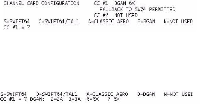
23-15-30 2-10
24 JUN 09
EMS SATCOM
SYSTEM DESCRIPTION, INSTALLATION, AND MAINTENANCE MANUAL
eNfusion™ HSD-440 High-speed Data Terminal
To select one OR:
1. Connect to the MPU of the HSD-440 terminal—see "Terminal MPU" on page 4-2 for
more information about connecting to the MPU.
2. To navigate to Menu 4, press CTRL + N.
3. To set ORs, press O.
4. To select an OR, type the number of that OR.
I. Configuring the Channel Cards for Swift64 and SBB
The channel cards access and assign priority to Swift64 and SBB services according to
the following rules:
• Give priority to SBB, but access Swift64 when SBB is not available
• Never permit access to Swift64
• Give priority to Swift64, but access SBB when Swift64 is not available
To configure a channel card for Swift64 and SBB
1. Connect a computer to the maintenance port of the HSD terminal. For more
information, refer to “Terminal MPU” on page 4-2.
2. To access the maintenance menus, type the password maint.
The password does not appear on the screen.
Maintenance menu 1 appears.
3. To navigate to maintenance menu 3, press CTRL + N.
4. To access miscellaneous EEPROM parameters, press m.
5. To access channel card configuration parameters, type 97, and then press ENTER.
The current channel card configuration appears. In the example below, channel card
one is operating as a Type 6 BGAN (SBB) terminal that can access Swift64 services
when SBB is not available.
6. To configure the operating mode of channel card one, press the key corresponding
to one of the options provided.
7. To configure the HSD-440 terminal to operate as a type 6 terminal, press 6.
The HSD-440 terminal can operate only as a type 6 terminal.
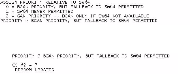
EMS SATCOM
SYSTEM DESCRIPTION, INSTALLATION, AND MAINTENANCE MANUAL
eNfusion™ HSD-440 High-speed Data Terminal
23-15-30 2-11
24 JUN 09
8. To assign a priority to Swift64 and SBB services, press the key corresponding to a
priority setting shown below.
The prompt for channel card two configuration appears.
9. To save changes, reset the HSD-440 terminal.
J. Removing the LED Label
A label covers the LES Access Codes LEDs. You can remove this label once you have
configured the LES Access Codes.
K. Activating Configurations
After configuring the HSD-440 terminal parameters, the HSD-440 terminal must be reset
using one of the following methods:
• In Menu 2, press Z
• Cycle the power to the HSD-440 terminal
• Press the reset or remote reset button on HSD-440 terminals installed in Stand-Alone
Mode
When the reset or restart is completed, the configuration values and parameters are
activated.
L. Verifying Configurations
This section describes how to view the HSD-440 terminal configuration parameters.
To view the HSD-440 terminal ORT system configuration:
1. In Menu 3, press H.
The List ORT appears.
2. Press 1 to display the CP ORT.
3. To scroll through the listing, press H.
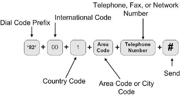
23-15-30 2-12
24 JUN 09
EMS SATCOM
SYSTEM DESCRIPTION, INSTALLATION, AND MAINTENANCE MANUAL
eNfusion™ HSD-440 High-speed Data Terminal
3. Using Terminals
This section describes how to:
• Place Swift64 voice and fax calls using the ISDN interface of the HSD-440 terminal
• Use the MPDS and Mobile ISDN data connections
• Operate the MCDU
• Operate Cockpit Communications
A. Placing Swift64 Voice and Fax Calls
Placing voice and fax calls using the HSD-440 terminal is similar to placing an international
telephone call or entering a telephone number for dial-up networking data calls. Like
international telephone numbers, the HSD-440 terminal dialing-number-sequence
includes different routing components or codes. Figure 2-1 illustrates the required order
of the dialing components.
Figure 2-1 Dialing-Sequence Components
Each dialing sequence component serves a different routing function:
• Dial Code Prefix:
Use service-specific Dial Code Prefixes when sending a fax or using analog modems,
or for overriding system defaults to force the system to request a specific service type.
Figure 2-1 uses the Dial Code Prefix for 3.1 KHz audio service type (*82*). See
Table 2-8 for other Dial Code Prefixes.
• International Access Code:
Use the international access code of the ground location when making ground-to-air
calls. The international access code for all airborne equipment is 00.
• Country Code:
Use the Public Switch Telephone Network (PSTN) number assigned to the country of
your call destination.

EMS SATCOM
SYSTEM DESCRIPTION, INSTALLATION, AND MAINTENANCE MANUAL
eNfusion™ HSD-440 High-speed Data Terminal
23-15-30 2-13
24 JUN 09
• Area Code (and City Code, if applicable):
Use the PSTN routing number assigned to the area (and if applicable, city) of your
call destination.
• POUND SIGN (#):
To signal the system to send the call, at the end of the telephone dial string, press or
enter POUND SIGN. Certain devices using the HSD-440 terminal may not have the
function to insert the POUND SIGN at the end of the dialing sequence. For those
devices, additional Dial Code Prefixes are required to override the send command
requirement. Refer to Table 2-9 for more information.
(1) Dial Code Prefixes
Although the system automatically selects the appropriate service types on outgoing
calls for ISDN devices, a Dial Code Prefix is required to send a fax, identify an
analogue modem, or force the system to override the system defaults to select a
specific service type (see Table 2-8).
The system requires the Dial Code Prefix *82* for sending faxes or when using
analogue modems. It forces the system to request the required 3.1 kHz audio service
from the Inmarsat Satellite Communications Network. If required, use the Dial Code
Prefixes to override the system defaults for selecting specific service types. Dial Code
Prefixes for all service types require an asterisk (*) before and after the code number.
Other Dial Code Prefixes provide system overrides required if you are using devices
that cannot add a POUND SIGN to the dialing string or devices that are slow dialing.
Table 2-8 provides a description of the additional Dial Code Prefixes used for system
overrides for Swift64 and SBB. Table 2-6 provides a list of the LESs and their
associated codes.
Note: Prefix *83* is not supported for SBB.
Table 2-8 Dial Code Prefixes for Forcing Service Type Selection
Service Type Service Description Dial Code Prefix
(Forces service
selection)
Speech 64 kbps High-Speed Voice *81*
AMBE+2 (SBB)
3.1 kHz audio Fax, analogue modem, STU-III, STE *82*
56 kbps data High-speed data *83*
64 kbps data High-speed data *84*

23-15-30 2-14
24 JUN 09
EMS SATCOM
SYSTEM DESCRIPTION, INSTALLATION, AND MAINTENANCE MANUAL
eNfusion™ HSD-440 High-speed Data Terminal
(2) Mobile-to-Mobile Communication
The HSD-440 terminal provides a two-way link for aircraft-to-aircraft communication.
Calling an aircraft requires additional information. You need to know the IMN of the
device or service on the aircraft you are calling. Table 2-10 lists the SNAC and the
Satellite OR number.
B. Using Data Connections
For information about data connections, optimizing your airborne network and selecting
the service that best meets your needs, refer to the HSD High-speed Data Terminal
Developer’s Guide, MN-1252-13005.
Refer to the HSD High-speed Data Terminal Setup Guide, MN-1110-10048, for instructions
on configuring dial-up networking connections.
Table 2-9 Dial Code Prefixes for System Overrides
Reason for Override Dial Code
Prefix Example Dialing Sequence
Use this Dial Code Prefix to override the
default LES configured in the system.
This Dial Code Prefix signals the system to
override the default LES and use the selected
LES instead. (See Figure 2-8 or contact
Inmarsat for Swift64 LES codes).
901 + LES
CODE 901 + LES CODE + International
Code + Country Code + Area Code +
Telephone Number + POUND KEY
901 + 002 + 00 + 1+ 613 +5551212
+ POUND KEY
Use with devices that cannot produce or add
a POUND SIGN to end the dialing sequence.
This Dial Code Prefix signals the system to
send the call after a specified delay in user
input when the POUND SIGN cannot be
entered.
902 902 + International Code + Country
Code + Area Code + Telephone
Number
902 + 00 + 1+ 613 + 5551212
Use with slow dialing devices that cannot
produce or add a POUND SIGN to end the
dialing sequence.
This Dial Code Prefix signals the system to
send the call after a specified delay in user
input.
903 903 + International Code + Country
Code + Area Code + Telephone
Number
903 + 00 + 1+ 613 + 5551212
Table 2-10 Satellite OR Codes
Code Name Code Number
SNAC 870
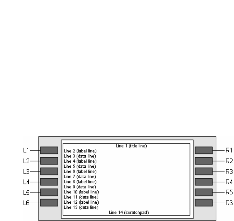
EMS SATCOM
SYSTEM DESCRIPTION, INSTALLATION, AND MAINTENANCE MANUAL
eNfusion™ HSD-440 High-speed Data Terminal
23-15-30 2-15
24 JUN 09
C. Operating the MCDU
The MCDU interface includes output and input ports, the screen, and the keyboard.
NOTE: The following descriptions apply to a Universal MCDU. Other MCDU types may
differ slightly.
(1) Output Ports
The MCDU transfers its identification and commands to the HSD-440 terminal using
32 bit words and a 12-14.5 kbps output port, as defined in ARINC Specification 429,
Digital Information Transfer System (DITS).
(2) Input Ports
The MCDU receives identification information and display data from individual
subsystems using seven input ports, as defined by ARINC Specification 429. Ports 1
and 2 are reserved for FMSs, and they operate at 100 kbps. Ports 3–7 are available
for the MCDU to communicate with the HSD-440 terminal, and they operate at 12-14.5
kbps.
(3) Screen
The MCDU displays all data on the screen, as shown in Figure 2-2.
Figure 2-2 MCDU Screen
The screen is divided into 14 rows and 24 columns. The first line is usually the title
line for the displayed menu. The last line, called the scratchpad, is where you can see
the data you have entered on the keyboard.
Between the title line and the scratchpad are six pairs of lines that correspond to the
six line select (LS) keys on either side of the screen. The upper line of each pair is
the label line, and the lower line is the data line. The six keys are designated left (L)
and right (R) and numbered 1–6 from top to bottom.
(4) Keyboard
The MCDU’s keyboard includes a set of numeric keys and a set of alphabetic keys,
both of which you can use to enter data into the MCDU.
The keyboard may include preset keys, such as the following:
• The IDX or MAIN MENU key: this key returns you to the MCDU’s main menu.

23-15-30 2-16
24 JUN 09
EMS SATCOM
SYSTEM DESCRIPTION, INSTALLATION, AND MAINTENANCE MANUAL
eNfusion™ HSD-440 High-speed Data Terminal
• The CLR key: this key clears any text you type into the scratchpad.
• The NEXT PAGE key: this key brings up the next page of a menu if one is
available.
You can program the other keys in the keyboard according to your requirements.
(5) Special Symbols
Because of space constraints on the screen, the MCDU uses a number of special
symbols to indicate actions:
•< and > appear at the far left or right to indicate that another menu page is available
in that direction.
•NUMBER/NUMBER appears to tell you which page out of how many pages you
are viewing. For example, 1/2 would appear when you are on page 1 of 2 pages
in total.
•* appears when an action is associated with that key. For example, pushing the
key beside the * could make a phone call, enter a password, or initiate a log off.
•[ and ] appear around the first item in a list. Each instance of a list should be below
a line item with a * beside it. You can push the key beside the * repeatedly to
display the other items in the list. See ARINC 739A, section 3 and Attachment 10
for details.
(6) Navigating the MCDU
The MCDU includes a number of menus, as shown in Figure 2-3.
Figure 2-3 MCDU Menus
This section will help you perform the following tasks:
•Modifying Logon Settings
•Viewing Channel Status
•Performing Maintenance
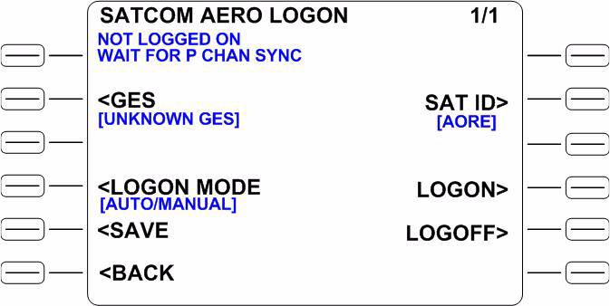
EMS SATCOM
SYSTEM DESCRIPTION, INSTALLATION, AND MAINTENANCE MANUAL
eNfusion™ HSD-440 High-speed Data Terminal
23-15-30 2-17
24 JUN 09
(7) Modifying Logon Settings
You can control how the HSD-440 terminal logs onto the network with the MCDU.
(a) Viewing the Logon Status
The logon status defines whether the HSD-440 terminal is currently logged on
or logged off.
To view the logon status:
1. On the second page of the MCDU’s main menu, press the key next to AERO
LOGON.
The SATCOM AERO LOGON menu appears, as shown in Figure 2-4. The
MCDU displays the log status on the line below SATCOM AERO LOGON
as LOGGED ON or NOT LOGGED ON.
Figure 2-4 SATCOM AERO LOGON Menu
(b) Selecting GESs
You can change the GES preferences using the MCDU.
To select a GES:
1. On the second page of the MCDU’s main menu, press the key next to AERO
LOGON.
The SATCOM AERO LOGON menu appears.
2. Press the key next to GES until the MCDU displays the GES you want to
associate with that channel.
3. Press the key next to SAVE.
(c) Changing Logon Mode
You can set the HSD-440 terminal to log on automatically or manually.
23-15-30 2-18
24 JUN 09
EMS SATCOM
SYSTEM DESCRIPTION, INSTALLATION, AND MAINTENANCE MANUAL
eNfusion™ HSD-440 High-speed Data Terminal
To change the logon mode:
1. On the second page of the MCDU’s main menu, press the key next to AERO
LOGON.
The SATCOM AERO LOGON menu appears.
2. Press the key next to LOGON MODE until the MCDU displays the desired
logon mode.
3. Press the key next to SAVE.
(d) Changing Logon Satellite ID
You can change the satellite ID to which the HSD-440 terminal will log on.
To change the logon satellite ID:
1. On the second page of the MCDU’s main menu, press the key next to AERO
LOGON.
The SATCOM AERO LOGON menu appears.
2. Press the key next to SAT ID until the MCDU displays the satellite ID to which
you want the HSD-440 terminal to log on.
3. Press the key next to SAVE.
(e) Logging on Manually
If you have configured the HSD-440 terminal to require a manual logon, you can
log on manually using the MCDU.
To log on manually:
1. On the second page of the MCDU’s main menu, press the key next to AERO
LOGON.
The SATCOM AERO LOGON menu appears.
2. To start the manual logon sequence, press the key next to LOGON.
CONFIRM appears on the line below LOGON when the logon sequence is
complete.
(f) Logging Off
You can initiate the log off sequence from the HSD-440 terminal with the MCDU.
To log off:
1. On the second page of the MCDU’s main menu, press the key next to AERO
LOGON.
The SATCOM AERO LOGON menu appears.
2. Press the key next to LOGOFF.
(8) Viewing Channel Status
From the second page of the MCDU’s main menu, you can view the status of each
of the four channels on the HSD-440 terminal.
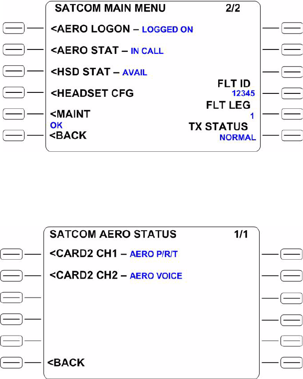
EMS SATCOM
SYSTEM DESCRIPTION, INSTALLATION, AND MAINTENANCE MANUAL
eNfusion™ HSD-440 High-speed Data Terminal
23-15-30 2-19
24 JUN 09
To view the status menu for a channel:
1. On the second page of the MCDU’s main menu, as shown in Figure 2-5,
press the key next to AERO STAT to view the SATCOM AERO STAT menu
or press the key next to HSD STAT to view the SATCOM HSD STAT menu.
The SATCOM AERO STAT menu is shown in Figure 2-6. The SATCOM HSD
STAT menu is shown in Figure 2-7.
Figure 2-5 SATCOM MAIN MENU (Page 2)
Figure 2-6 SATCOM AERO STATUS Menu

23-15-30 2-20
24 JUN 09
EMS SATCOM
SYSTEM DESCRIPTION, INSTALLATION, AND MAINTENANCE MANUAL
eNfusion™ HSD-440 High-speed Data Terminal
Figure 2-7 SATCOM HSD STATUS Menu
2. On the SATCOM AERO STAT menu or the SATCOM HSD STAT menu, press
the key next to the channel for which you wish to view the status.
The menu for Aero Card 2, Channel 1 is shown in Figure 2-8. The menu for
HSD Card 1, Channel 1 is shown in Figure 2-9. Similar menus are available
for the remaining channel cards.
Figure 2-8 SATCOM AERO CARD2 CH1 STAT Menu
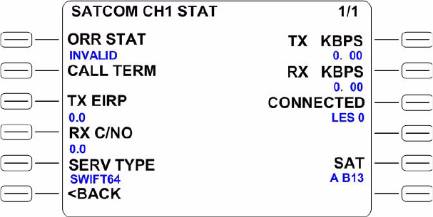
EMS SATCOM
SYSTEM DESCRIPTION, INSTALLATION, AND MAINTENANCE MANUAL
eNfusion™ HSD-440 High-speed Data Terminal
23-15-30 2-21
24 JUN 09
Figure 2-9 SATCOM HSD CARD1 CH1 STAT Menu
On the channel status menu (Figure 2-8 and Figure 2-9), you can view the following
detailed information about the operation of a channel:
• Logon status
• Call termination code
• Transmitter Effect Isotropic Radiated Power (EIRP)
• Receiver carrier-to-noise ratio
• Service type
• Number of bits transmitted per second (kbps)
• Number of bits received per second (kbps)
• Service information
• Satellite ID
(a) Viewing the Logon Status
To view the logon status for AERO channels:
• On the SATCOM AERO STAT menu, press the key next to channel for which
you wish to view the logon status.
The MCDU displays the logon status on the line below LOGON as either
VALID or INVALID.
To view the logon status for HSD channels:
• On the SATCOM HSD STAT menu, press the key next to channel for which
you wish to view the logon status.
The MCDU displays the logon status on the line below ORR STAT as either
VALID or INVALID.

23-15-30 2-22
24 JUN 09
EMS SATCOM
SYSTEM DESCRIPTION, INSTALLATION, AND MAINTENANCE MANUAL
eNfusion™ HSD-440 High-speed Data Terminal
(b) Viewing the Call Termination Code
The call termination code is a two-digit number that corresponds to a call
termination reason, such as a line failure.
NOTE: Call Termination Code is not available for Aero channels.
To view the call termination code for HSD channels:
• On the SATCOM HSD STAT menu, press the key next to channel for which
you wish to view the call termination code.
The MCDU displays the call termination code on the line below CALL TERM.
(c) Viewing the Transmitter EIRP
To view the transmitter EIRP:
• On the SATCOM AERO STAT menu or SATCOM HSD STAT menu, press
the key next to channel for which you wish to view the transmitter EIRP.
The MCDU displays the transmitter EIRP on the line below TX EIRP.
(d) Viewing the Receiver Carrier-to-Noise Ratio
To view the receiver carrier-to-noise ratio:
• On the SATCOM AERO STAT menu or SATCOM HSD STAT menu, press
the key next to channel for which you wish to view the receiver
carrier-to-noise ratio.
The MCDU displays the receiver carrier-to-noise ratio on the line below RX
C/NO.
(e) Viewing the Service Type
The MCDU displays the service type as an acronym.
To view the service type:
• On the SATCOM AERO STAT menu or SATCOM HSD STAT menu, press
the key next to channel for which you wish to view the service type.
The MCDU displays the service type on the line below SERV TYPE.
(f) Viewing the Number of Bits Transmitted Per Second
The number of bits being transmitted per second is expressed in kilobits per
second (kbps).
To view the number of bits being transmitted per second:
• On the SATCOM AERO STAT menu or SATCOM HSD STAT menu, press
the key next to channel for which you wish to view the number of bits being
transmitted per second.
The number of bits being transmitted per second are displayed on the line
below TX KBPS. When a circuit switched service has been selected or
configured, the MCDU screen displays no data.
(g) Viewing the Number of Bits Received Per Second
The number of bits being received per second is expressed in kilobits per second
(kbps).

EMS SATCOM
SYSTEM DESCRIPTION, INSTALLATION, AND MAINTENANCE MANUAL
eNfusion™ HSD-440 High-speed Data Terminal
23-15-30 2-23
24 JUN 09
To view the number of bits being received per second:
• On the SATCOM AERO STAT menu or SATCOM HSD STAT menu, press
the key next to channel for which you wish to view the number of bits being
received per second.
The number of bits being received per second are displayed on the line below
RX KBPS. When a circuit switched service has been selected or configured,
the MCDU screen displays no data.
(h) Viewing Service Information
If you have Aero service, service information includes the GES number and name
description. If you have GAN (Swift64) service, service information includes the
service provider number and name description.
To view service information:
• On the SATCOM AERO STAT menu or SATCOM HSD STAT menu, press
the key next to channel for which you wish to view service information.
The MCDU displays the service information on the line below CONNECTED.
(i) Viewing Satellite IDs
Satellite IDs include the index number of each satellite, a mnemonic and
abbreviated alphanumeric description, and the number of the spot beam that the
HSD-440 terminal is currently using.
To view satellite IDs:
• On the SATCOM AERO STAT menu or SATCOM HSD STAT menu, press
the key next to channel for which you wish to view satellite IDs.
The MCDU displays the satellite IDs on the line below SAT.
NOTE: All channels and channel cards must be logged into the same
satellite; however, they may be operating through different spot
beams.
(9) Performing Maintenance
You can modify headset configuration and initiate self-tests on the HSD-440 terminal
from the MCDU.
(a) Modifying Headset Configuration
You can modify some headset configurations using the MCDU, including the
cockpit voice levels and noise insertion level.
The cockpit voice level refers to the level at which the cockpit microphone
transmits its signal and the level at which the headset/speaker receives its signal.
Noise insertion minimizes the amount of noise modulation you hear when the
GES drops its carrier in the forward direction during speech pauses.
To modify headset configuration:
1. On the second page of the MCDU’s main menu, as shown in Figure 2-5,
press the key next to HEADSET CFG.
The SATCOM HEADSET CONFIG menu appears, as shown in Figure 2-10.
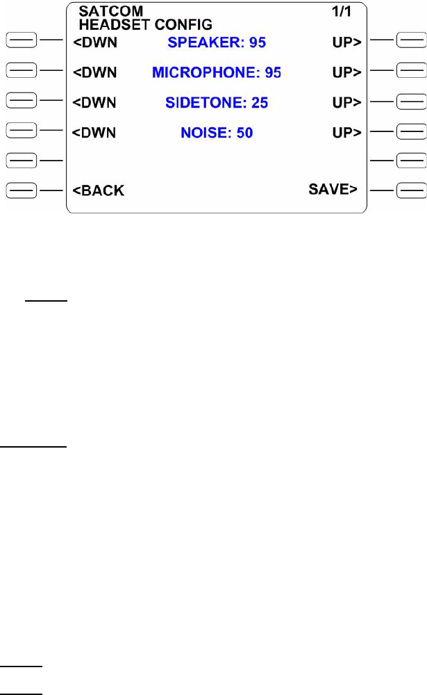
23-15-30 2-24
24 JUN 09
EMS SATCOM
SYSTEM DESCRIPTION, INSTALLATION, AND MAINTENANCE MANUAL
eNfusion™ HSD-440 High-speed Data Terminal
Figure 2-10 SATCOM HEADSET CONFIG Menu
NOTE: The numbers move up and down by increments and decrements of
5.
2. To increase or decrease the speaker, microphone, sidetone, and noise
insertion levels, press the keys next to DWN and UP.
3. Press the key next to SAVE.
(b) Initiating a Person Activated Self Test (PAST)
CAUTION: INITIATING A PAST DROPS ANY VOICE OR DATA CALLS THAT
ARE IN PROGRESS.
A PAST completely resets the HSD-440 terminal. The HSD-440 terminal drops
any telephone calls that are in progress, and the AES drops off the Inmarsat
satellite communications system. When the HSD-440 terminal reboots, updated
BITE data appears on the appropriate screens in the MCDU. This is equivalent
to a POST.
The HSD-440 terminal performs a self-test during the power up sequence. You
can initiate a PAST by pressing the TEST button on the front panel of the
HSD-440 terminal and holding it down for three seconds or more. You can also
initiate a PAST through the MCDU.
NOTE: You can only initiate a PAST when the aircraft is on the ground.
NOTE: You can only access the MAINT menu if the “Allow MCDU PAST” ORT
setting is enabled.
To initiate a PAST:
1. On the second page of the MCDU’s main menu, press the key next to MAINT.
The SATCOM DIAG menu appears, as shown in Figure 2-11.
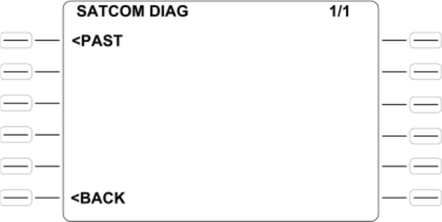
EMS SATCOM
SYSTEM DESCRIPTION, INSTALLATION, AND MAINTENANCE MANUAL
eNfusion™ HSD-440 High-speed Data Terminal
23-15-30 2-25
24 JUN 09
Figure 2-11 SATCOM DIAG Menu
2. To initiate the PAST, press the key next to PAST.
D. Cockpit Communications
This section provides instructions for making calls with the MCDU and 4-wire voice
services available in the aircraft’s cockpit. The cockpit communications system operates
with a headset in the aircraft’s cockpit.
(1) Modes of Operation
The cockpit communication services are configured in one of two modes of operation
before installation: Latched mode and Push-to-Talk (PTT) mode. These configurations
are strapped at the terminal and cannot be changed without removing and rewiring
the terminal.
In PTT mode, a telephone number can be dialed only using the MCDU keys, not with
the switches on the cockpit communication console. In Latched mode, a call to a
telephone number loaded into the MCDU can be initiated using the switches on the
audio Control Panel (ACP), and calls can be answered and ended with the switches
and the MCDU buttons.
(2) Accepting and Making Calls
You can accept and make air-to-ground and air-to-air voice calls using the HSD-440
terminal, the MCDU, the ACP, and a 4-wire cockpit headset.
The way in which you can accept or make calls depends on the mode in which your
4-wire cockpit headset is strapped: PTT mode or Latched mode.
(a) PTT Mode
You can use the MCDU and ACP to accept calls, make air-to-ground calls, and
make air-to-air calls in PTT mode. You can make new calls or dial previously
saved telephone numbers from the MCDU’s telephone directory.

23-15-30 2-26
24 JUN 09
EMS SATCOM
SYSTEM DESCRIPTION, INSTALLATION, AND MAINTENANCE MANUAL
eNfusion™ HSD-440 High-speed Data Terminal
1. Accepting Calls in PTT Mode
You can use the MCDU and ACP to accept incoming calls, including when
another call is in progress. The combination of lights and chimes that alert
you to an incoming call depends on the way in which the HSD-440 terminal
was strapped during its installation.
To accept a call in PTT mode:
1. To accept the call:
• On the first page of the MCDU’s main menu, as shown in Figure 2-12,
press the key next to ANSWER.
or
• On the ACP, assert the PLACE/END CALL 1 switch or close the
PTT 1 switch.
Figure 2-12 SATCOM MAIN MENU (Page 1 of 2)
2. To end the call:
• On the MCDU, press the key next to END.
or
• On the ACP, assert the PLACE/END CALL 1 switch or open the
PTT 1 switch.
To accept a call in PTT mode when another call is in progress:
1. To accept the call, on the first page of the MCDU’s main menu, press the
key next to ACCEPT.
The original call ends.

EMS SATCOM
SYSTEM DESCRIPTION, INSTALLATION, AND MAINTENANCE MANUAL
eNfusion™ HSD-440 High-speed Data Terminal
23-15-30 2-27
24 JUN 09
2. To end the call:
• On the MCDU, press the key next to END.
or
• On the ACP, assert the PLACE/END CALL 1 switch or open the
PTT 1 switch.
2. Making New Calls in PTT Mode
Making calls using the HSD-440 terminal is similar to placing an international
telephone call. Air-to-ground telephone numbers include an international
access code, country code, and area code. Air-to-air telephone numbers
include a SNAC or OR and an IMN.
International access codes and country codes are shown in Appendix G:
“International Access and Country Codes” on page G-1.
OR numbers are shown in Table 2-11.
To make a new call in PTT mode:
1. On the first page of the MCDU’s main menu, type the full telephone number
you want to call into the MCDU keyboard.
2. To set the priority for your call using Table 2-12, press the key next to
PRIORITY.
Table 2-11 OR Numbers
OR OR number
AOR-E 871
AOR-W 874
POR 872
IOR 873
Table 2-12 Priority Codes
Call priority Description
EMG Emergency—used for distress or urgent calls
OP-HI Operational-High—used for Flight Safety communications
OP-LO Operational-Lo—used for Regularity of Flight,
Meteorological or Administrative communications
NON-OP Non-Operational—used for Non Safety of Flight or public
phone call (cabin) communications
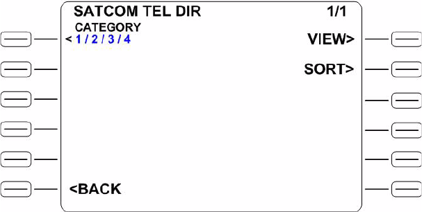
23-15-30 2-28
24 JUN 09
EMS SATCOM
SYSTEM DESCRIPTION, INSTALLATION, AND MAINTENANCE MANUAL
eNfusion™ HSD-440 High-speed Data Terminal
3. To dial the call:
• On the MCDU, press the key next to DIAL NOW.
or
• On the ACP, assert the PLACE/END CALL 1 switch or close the
PTT 1 switch.
4. To end the call:
• On the MCDU, press the key next to END.
or
• On the ACP, assert the PLACE/END CALL 1 switch or open the
PTT 1 switch.
3. Making Calls from the Telephone Directory in PTT Mode
You can make voice calls from the numbers you have saved in the MCDU’s
telephone directory.
To make a call from the telephone directory in PTT mode:
1. On the first page of the MCDU’s main menu, press the key next to TEL DIR.
The SATCOM TEL DIR menu appears, as shown in Figure 2-13.
Figure 2-13 SATCOM TEL DIR Menu
2. Press the key next to CATEGORY to select a phone book.
The SATCOM TEL CAT menu appears, as shown in Figure 2-14.
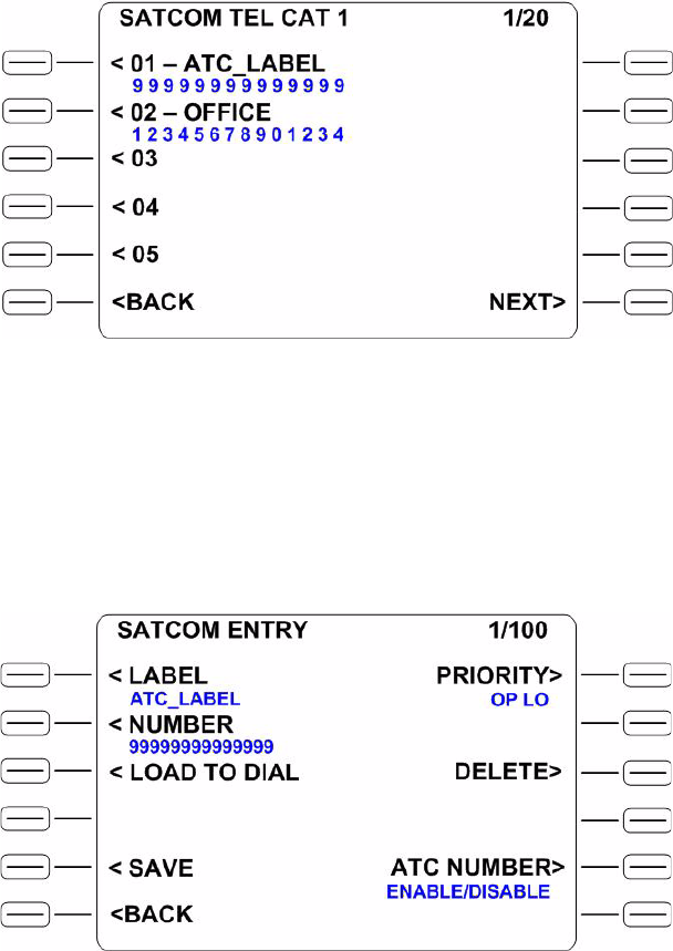
EMS SATCOM
SYSTEM DESCRIPTION, INSTALLATION, AND MAINTENANCE MANUAL
eNfusion™ HSD-440 High-speed Data Terminal
23-15-30 2-29
24 JUN 09
Figure 2-14 SATCOM TEL CAT 1 (Page 1 of 20)
3. Press the key next to the entry you want to dial.
The SATCOM ENTRY menu appears, as shown in Figure 2-15.
Figure 2-15 SATCOM ENTRY Menu (Page 1 of 100)
4. To load the telephone number, press the key next to LOAD TO DIAL.
The MCDU’s main menu appears, as shown in Figure 2-16.
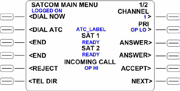
23-15-30 2-30
24 JUN 09
EMS SATCOM
SYSTEM DESCRIPTION, INSTALLATION, AND MAINTENANCE MANUAL
eNfusion™ HSD-440 High-speed Data Terminal
Figure 2-16 SATCOM MAIN MENU (Page 1 of 2)
5. To dial the call:
• On the MCDU, press the key next to DIAL NOW.
or
• On the ACP, assert the PLACE/END CALL 1 switch or close the
PTT 1 switch.
6. To end the call:
• On the MCDU, press the key next to END.
or
• On the ACP, assert PLACE/END CALL 1 switch or open the PTT 1
switch.
(b) Latched Mode
You can use the MCDU and ACP to accept calls, make air-to-ground calls, and
make air-to-air calls in Latched mode. You can make new calls or dial previously
saved telephone numbers from the MCDU’s telephone directory.
1. Accepting Calls in Latched Mode
You can use the MCDU and ACP to accept incoming calls, including when
another call is in progress. The combination of lights and chimes that alert
you to an incoming call depends on the way in which the HSD-440 terminal
was strapped during its installation.
To accept a call in Latched mode:
1. To accept the call, on the ACP, close the PTT 1 switch.
2. To end the call:
• On the ACP, open the PTT 1 switch or assert the
PLACE/END CALL 1 switch.
or

EMS SATCOM
SYSTEM DESCRIPTION, INSTALLATION, AND MAINTENANCE MANUAL
eNfusion™ HSD-440 High-speed Data Terminal
23-15-30 2-31
24 JUN 09
• On the MCDU, press the key next to END.
To accept a call in Latched mode when another call is in progress:
1. To accept the call, on the first page of the MCDU’s main menu, press the
key next to ACCEPT.
The original call ends.
2. To end the call:
• On the ACP, open the PTT 1 switch or assert the
PLACE/END CALL 1 switch.
or
• On the MCDU’s main menu, press the key next to END.
2. Making Calls in Latched Mode
Making calls using the HSD-440 terminal is similar to placing an international
telephone call. Air-to-ground telephone numbers include an international
access code, country code, and area code. Air-to-air telephone numbers
include a SNAC or OR and an IMN.
To make a new call in Latched mode:
1. On the first page of the MCDU’s main menu, type the full telephone number
you want to call into the MCDU keyboard.
2. To set the priority for your call using Table 2-13, press the key next to
PRIORITY.
3. Press the key next to LOAD NUMBER.
The full telephone number appears under DIAL NOW.
4. To dial the telephone number, on the ACP, close the PTT 1 switch.
5. To end the call:
• On the ACP, open the PTT 1 switch or assert the
PLACE/END CALL 1 switch.
or
• On the MCDU’s main menu, press the key next to END.
Table 2-13 Priority Codes
Call priority Description
EMG Emergency—used for distress or urgent calls
OP-HI Operational-High—used for Flight Safety communications
OP-LO Operational-Lo—used for Regularity of Flight, Meteorological or
Administrative communications
NON-OP Non-Operational—used for Non Safety of Flight or public phone call
(cabin) communications
23-15-30 2-32
24 JUN 09
EMS SATCOM
SYSTEM DESCRIPTION, INSTALLATION, AND MAINTENANCE MANUAL
eNfusion™ HSD-440 High-speed Data Terminal
3. Making Calls from the Telephone Directory in Latched Mode
You can make voice calls from the numbers you have saved in the MCDU’s
telephone directory.
To make a call from the telephone directory in Latched mode:
1. On the first page of the MCDU’s main menu, press the key next to TEL DIR.
The SATCOM TEL DIR menu appears.
2. Press the key next to CATEGORY to select a phone book.
The SATCOM TEL CAT menu appears.
3. Press the key next to the entry you want to dial.
The SATCOM ENTRY menu appears.
4. To load the telephone number, press the key next to LOAD TO DIAL.
The MCDU’s main menu appears.
5. On the ACP, select CH1 SATCOM.
6. To dial the telephone number, on the ACP, close the PTT 1 switch.
7. To end the call:
• On the ACP, open the PTT 1 switch or assert the
PLACE/END CALL 1 switch.
or
• On the MCDU’s main menu, press the key next to END.
(c) Saving Telephone Numbers in the Telephone Directory
You can save telephone numbers to the MCDU’s telephone directory to use later,
and you can dial telephone numbers from the telephone directory.
1. Saving a New Directory Entry
To save new telephone numbers to the telephone directory:
1. On the first page of the MCDU’s main menu, press the key next to TEL DIR.
The SATCOM TEL DIR menu appears.
2. Press the key next to CATEGORY to select a phone book.
The SATCOM TEL CAT menu appears.
3. Press a key next to an empty entry. If there is no empty entry available on
the first page, press the key next to NEXT until a free entry appears.
A SATCOM ENTRY menu appears for this new telephone number.
4. Type the name you want to give this telephone number into the MCDU’s
keyboard.
5. To store the label, press the key next to LABEL.
6. Type the telephone number for this entry into the MCDU’s keyboard.
7. To store the telephone number, press the key next to NUMBER.

EMS SATCOM
SYSTEM DESCRIPTION, INSTALLATION, AND MAINTENANCE MANUAL
eNfusion™ HSD-440 High-speed Data Terminal
23-15-30 2-33
24 JUN 09
8. Press the key next to PRIORITY repeatedly until the priority you want to
associate with this telephone number appears.
NOTE: When you designate a telephone number as the ATC telephone
number, any other telephone number that was designated as ATC
loses that designation. Only one telephone number can be
designated as the ATC telephone number.
9. To make this telephone number the ATC telephone number, press the key
next to ATC NUMBER.
10.To save your entry, press the key next to SAVE.
NOTE: The SAVE option does not appear until you make a change to the
entry.
2. Modifying an Existing Directory Entry
To modify an existing entry in the directory:
1. On the first page of the MCDU’s main menu, press the key next to TEL DIR.
The SATCOM TEL DIR menu appears.
2. Press the key next to CATEGORY to select a phone book.
The SATCOM TEL CAT menu appears.
3. Press the key next to the entry you wish to modify.
The SATCOM ENTRY menu appears for this entry.
4. Type the name you want to give this telephone number into the MCDU’s
keyboard.
5. To store the label, press the key next to LABEL.
6. Type the telephone number for this entry into the MCDU’s keyboard.
7. To store the telephone number, press the key next to NUMBER.
8. Press the key next to PRIORITY repeatedly until the priority you want to
associate with this telephone number appears.
NOTE: When you designate a telephone number as the ATC telephone
number, any other telephone number that was designated as ATC
loses that designation. Only one telephone number can be
designated as the ATC telephone number.
9. To make this telephone number the ATC telephone number, press the key
next to ATC NUMBER.
10.To save your entry, press the key next to SAVE.
NOTE: The SAVE option does not appear until you make a change to the
entry.
23-15-30 2-34
24 JUN 09
EMS SATCOM
SYSTEM DESCRIPTION, INSTALLATION, AND MAINTENANCE MANUAL
eNfusion™ HSD-440 High-speed Data Terminal
Blank Page
EMS SATCOM
SYSTEM DESCRIPTION, INSTALLATION, AND MAINTENANCE MANUAL
eNfusion™ HSD-440 High-speed Data Terminal
23-15-30 3-1
24 JUN 09
INSTALLATION
This section describes the procedures required to install HSD-440 terminals on an aircraft,
including the following sections:
•Advisories
•Pre-Installation Inspection
•ARINC 600 Trays and Connectors
•Mechanical Installation
•Electrical Installation
•Installation and Engineering Diagrams
1. Advisories
Before performing any installation procedures, read the safety advisories listed in the
Introduction on page INTRO–6 of this manual.
2. Pre-Installation Inspection
Before installing any HSD-440 terminal, conduct a pre-installation inspection of all parts to
make sure that no damage occurred during shipping:
• Unpack the HSD-440 terminal(s) from the shipping container(s).
• Verify that the part number displayed on the shipping box and equipment component
matches the model and part number ordered. If components are missing from the
shipment, contact the supplier or EMS SATCOM Product Support immediately and report
the problem.
• Visually inspect the terminal for any shipping damage. If any shipping damage has
occurred, contact the shipping carrier immediately and report the problem.
• Check the HSD-440 terminal connectors for corrosion and damage. If damage is noted,
do not apply power to the terminal. Contact the supplier or EMS SATCOM Product Support
immediately to report the problem.
3. ARINC 600 Trays and Connectors
This section provides detailed information on the ARINC 600 trays provided in the HSD-440
Installation Kits.
The HSD-440 LRU is installed in a standard, ARINC 600, 8-MCU tray. Ruggedized trays
designed specifically for installations on helicopter aircraft are also available.
A. Installation Kits
Installation kits for HSD-440 terminals are available from EMS SATCOM. Contact the EMS
SATCOM Sales department for more information on how to select and order the
appropriate HSD-440 Terminal Installation Kit.

23-15-30 3-2
24 JUN 09
EMS SATCOM
SYSTEM DESCRIPTION, INSTALLATION, AND MAINTENANCE MANUAL
eNfusion™ HSD-440 High-speed Data Terminal
Table 3-1 lists the recommended installation kits for typical installations.
B. Cabling Notes
Before proceeding with the installation of the HSD-440 terminal, read all cabling notes
provided on the HSD-440 Terminal Interconnection and Contact Assignment drawings
(refer to Figure 3-11 and Figure 3-12).
(1) Cabling
When installing the HSD-440 terminal, follow the cabling requirements listed below:
• Maximum recommended cable length is 50 feet.
• LAN cables must meet flammability, TIA/EIA568-A CAT 5 requirements and
conform to ARINC 628 specifications.
• Wire size recommendations:
•For +28 V dc HOT (BP2), +28 V dc RTN GND (BP3), 115 V ac COLD (BP7),
and Chassis GND (BP8), use 12 AWG
•For 115 V ac HOT (BP1), use 20 AWG
• Unless otherwise specified, for signaling, use 22 AWG
(2) Coaxial Cable Loss Considerations
When installing HSD-440 terminals, consider the following coaxial cable loss
requirements:
• Transmit cable: Maximum loss is 2.5 dB, including DLNA (typically <0.8 dB), as
per ARINC 741. In installations that use a high power relay, the high power relay
loss must be included.
• Receive cable: For HSD-440 terminals operating in Stand-Alone Mode, the
minimum loss is 6–25 dB (including any in-line attenuator), as per ARINC 741.
4. Mechanical Installation
This section describes the mechanical installation requirements for the HSD-440 terminals.
The Outline and Installation diagrams are provided at the end of this section, in Figure 3-7
and Figure 3-8.
Table 3-1 Installation Kits
Installation Kit Name EMS SATCOM
Part Number Description
HSD-440 Installation Kit
AC FAN 1110-F-0120-01 Standard Installation Kit: Bottom AC Fan
Tray Assembly and ARINC Connector
(Un-pressurized Installation)
HSD-440 Installation Kit
DC FAN 1110-F-0120-02 Standard Installation Kit: Bottom DC Fan
Tray Assembly and ARINC Connector
(Un-pressurized Installation)
8-MCU ARINC 600 Tray
with four isolators H64-BA-15 (Barry
Controls) Vibration-mount installation kit.
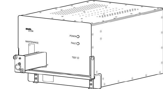
EMS SATCOM
SYSTEM DESCRIPTION, INSTALLATION, AND MAINTENANCE MANUAL
eNfusion™ HSD-440 High-speed Data Terminal
23-15-30 3-3
24 JUN 09
This section contains the information required to plan the physical placement of the HSD-440
terminals.
The Outline and Installation diagrams, shown in Figure 3-7 and Figure 3-8, illustrate the
physical and mechanical specifications of the HSD-440 terminal.
In typical aircraft installations, the HSD-440 terminal assembly fits into standard ARINC,
8-MCU mounting trays. Specialized trays that meet the requirements for installations of the
HSD-440 terminals on Helicopters are also available from EMS SATCOM.
All HSD-440 terminal ARINC installation trays are included in the Installation Kits. Table 3-1
describes the HSD-440 terminal Installation Kits available from EMS SATCOM.
A. Physical Placement
When selecting a location for the HSD-440 terminal, allow for adequate spacing for the
installation while providing reasonable access for servicing. Leave a minimum gap of 0.5
inches between LRUs.
B. SCM Installation
The SCM holds SIM cards that contain data for the operation of SBB services.
To remove the SCM:
1. Remove the two screws from the front panel of the HSD-440 terminal.
2. Remove the SCM from the HSD-440 terminal, as shown in Figure 3-1.
Figure 3-1 HSD-440 Terminal SCM
To install the SCM:
1. Insert the SCM into the slot on the front panel of the HSD-440 terminal.
2. Tighten the two screws on the SCM.

23-15-30 3-4
24 JUN 09
EMS SATCOM
SYSTEM DESCRIPTION, INSTALLATION, AND MAINTENANCE MANUAL
eNfusion™ HSD-440 High-speed Data Terminal
C. Environmental Requirements
The environmental requirements that must be considered during the physical placement
of the HSD-440 terminals are based on the RTCA/DO-160E Environmental Specifications
detailed in "System Description" on page 1-1.
The standard mounting trays for the HSD-440 terminal offer a number of fan configuration
options depending on the physical placement of the LRU in the aircraft.
(1) Heating and Cooling
Refer to "System Description" on page 1-1 for a complete listing of the RTCA/DO-160E
Environmental Specifications for the HSD-440 terminals.
When selecting an installation location for the HSD-440 terminal, consider the heating
and cooling requirements listed below:
• Power Dissipation (AC/DC models): 275 Watts nominal, 400 Watts maximum
• Cooling Air: per ARINC 600
• Recommended Flow rate: 88 kg/hr (185 lbs/hr)
• Pressure drop: 5 ±3 mm (0.07 ±0.025 in.) H2O
(2) Fan Tray Requirements
WARNING: FAILURE TO INSTALL AND CONFIGURE THE FAN TRAY
ASSEMBLY AS INSTRUCTED MAY SERIOUSLY COMPROMISE
THE HSD-440 TERMINAL'S EXTREME TEMPERATURE
OPERATION.
Fan tray assemblies may be shipped with or without hole-plug-buttons installed. For
adequate airflow to the HSD-440 terminal subassemblies, the plugs must be installed
or removed in the fan/tray configuration, as illustrated in Figure 3-2.
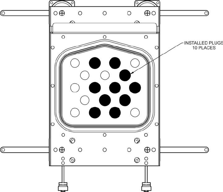
EMS SATCOM
SYSTEM DESCRIPTION, INSTALLATION, AND MAINTENANCE MANUAL
eNfusion™ HSD-440 High-speed Data Terminal
23-15-30 3-5
24 JUN 09
Figure 3-2 Fan Tray Plug Configuration (black = installed, white = removed)
D. Chassis Grounding
The HSD-440 terminal tray-mounted assemblies must be electrically bonded to the
airframe. Make sure that the mating surfaces are free from contaminants such as paints
or other non-conductive elements. Where surface preparations are insufficient to ensure
a proper bond, the use of a short, tin-coated, copper bonding strap of at least 6.35 mm
(0.25 in.) in width is recommended. The LRU and tray assemblies should provide a low
impedance path of <0.2 ohms.
5. Electrical Installation
This section provides electrical installation details for HSD-440 terminals. This section is
divided into sub-sections that provide the wiring details for the currently supported modes of
operation.
A. Stand-Alone Mode Installation
(1) Cabling and Connector Requirements
This section provides general electrical installation information on power, ground,
shielding requirements, and cabling.

23-15-30 3-6
24 JUN 09
EMS SATCOM
SYSTEM DESCRIPTION, INSTALLATION, AND MAINTENANCE MANUAL
eNfusion™ HSD-440 High-speed Data Terminal
(a) Power Requirements
The HSD-440 terminal can operate from the aircraft’s +28 V dc or 115 V ac,
400 Hz (nominal) power supply. If both power sources are connected, the
terminal will use the 115 V ac supply.
(b) Ground Requirements
Improper grounding can lead to ground loops and induced Electromagnetic
Interference (EMI) or Radio Frequency Interference (RFI). When installing an
HSD-440 terminal, follow standard grounding practices for both chassis and
cabling shields. Refer to "Chassis Grounding" on page 3-5 for chassis and tray
grounding instructions.
(c) Cable Shielding and Termination
The preferred method of cable shield termination is in accordance with NEMA
WC 27500:2000 and ARINC 741. ARINC Report 413A—Guidance for Aircraft
Electrical Power Utilization and Transient Protection provides more detailed
information in Attachment 3-2, Wire Shielding and Grounding Requirements and
in Appendix 7.
Unless otherwise stated, all cable shields must be connected to the closest
aircraft ground at both ends of the cable and on both sides of any production
break in the cable. Where applicable, terminate shields with connectors via the
backshell or via a pigtail with a suitable termination to the closest aircraft ground.
General aviation cable-routing guidelines apply. See Table 3-2 for detailed
information.
NOTE: Typically, Ethernet and ISDN cables have multiple shields; terminate
each shield separately.
Table 3-2 Cable Shielding and Termination Specifications
Cable Function Conductor Type
(Typical) Single Point Multiple
Point Minimum
Conductor
Coverage By
Shield
Power Lines Single conductor,
stranded N/A N/A N/A
Digital Control Twisted pair, stranded Yes 85%

EMS SATCOM
SYSTEM DESCRIPTION, INSTALLATION, AND MAINTENANCE MANUAL
eNfusion™ HSD-440 High-speed Data Terminal
23-15-30 3-7
24 JUN 09
(2) Installation Wiring Notes
(a) SDI
SDI is provided for the as per ARINC 741 specifications. Pins marked 0 are left
open-circuit and pins marked 1 are strapped on the airframe side of the connector
to the pin assigned as SDI Common (TP5D). For this HGA application, pin TP5B
(1) should be strapped and TP5A (0) should be left open.
NOTE: The logic for the SDI/WOW is explained in ARINC 741 Characteristic
Attachment 1-4, Note 19. This SDI/WOW logic in this case (where 0=open
and 1=strapped to common) is the reverse of the logic applied to all other
HSD-440 terminal connectors, FWD ID, System Config, and Data I/O
Config, where 0=strapped to common and 1=open.
(b) Maintenance Port Interface
The HSD-440 terminal has an RS-232 maintenance port interface that provides
access to the MPU for data loading, system monitoring, and testing purposes.
Access to the HSD-440 terminal MPU is achieved by connecting an RS-232,
VT-100 terminal (PC or laptop operating a terminal emulation program) to the
RS-232 maintenance port.
The HSD-440 terminal maintenance port is available at the front of the HSD-440
terminal and at the rear ARINC 600 connector. Connection on the front of the
HSD-440 terminal is accessible via a DB25S connector for local maintenance of
the terminal. Remote access is provided for cases where local access is
unavailable. For remote access, install an accessible DB9S connector in the
cabin area.
NOTE: The front panel and remote connections to the maintenance port cannot
be used simultaneously.
Serial data Twisted pair, stranded Yes 85%
Ethernet data Twisted pair, stranded Yes 85%
ISDN data Twisted pair, stranded Yes 85%
Discrete Lines Single conductor,
stranded N/A N/A N/A
RF TX and RX Coaxial Yes 95%
Definitions
Single Point: Cable shield terminated at one end only via a connector or suitable crimp
terminal.
Multiple Point: Cable shield terminated at both ends via a connector or suitable crimp
terminal, usually at both ends of the cable and at both sides of any production break.
N/A: Not applicable.
Table 3-2 Cable Shielding and Termination Specifications (Continued)
Cable Function Conductor Type
(Typical) Single Point Multiple
Point Minimum
Conductor
Coverage By
Shield
23-15-30 3-8
24 JUN 09
EMS SATCOM
SYSTEM DESCRIPTION, INSTALLATION, AND MAINTENANCE MANUAL
eNfusion™ HSD-440 High-speed Data Terminal
Refer to "Test and Fault Isolation" on page 4-1 for information on how to connect
and use the maintenance port, including equipment requirements, connection
and cabling requirements, software loading instructions, and configuration
details.
(c) Antenna Subsystem RF Interface
Several external RF parameters (such as cable losses and antenna gain) that
must be delimited to ensure proper operation dictate the HSD-440 terminal
performance requirements.
Table 3-3 defines the RF parameters and their expected values.
(d) WOW Pin Wiring
The WOW1 and WOW2 pins are either left open circuit or connected to the
airframe DC ground through a ground proximity switch. The WOW Program
Select (PGM) pin is either left open circuit or connected to the Forward Address
Common. The two ground states for any pin are open and closed circuit.
Resolve any conflict between WOW1 and WOW2 by assuming the aircraft is
in-air. The interpretation of the state of the WOW1 and WOW2 pins is defined by
the state of the WOW program select pin. Refer to Table 3-4 for details.
Table 3-3 RF Parameters Definitions
Parameter Min. Value (dB) Max. Value (dB)
Antenna Gain 817
Antenna to DLNA Loss 0.3
DLNA Gain 53 60
DLNA Noise Figure 1.8
DLNA to HSD-440 terminal (Rx) Loss 625
HSD-440 terminal to Antenna (Tx) Loss 12.5 (including
DLNA loss)
DLNA Insertion Loss (Tx to Antenna Port) –0.8
Table 3-4 WOW Pin Wiring Table
Pin Name and Location Aircraft Status
WOW1 WOW2 PGM
TP3G TP3K TP3J
CLOSED CLOSED CLOSED In-air
OPEN CLOSED CLOSED Not valid—Default in-air

EMS SATCOM
SYSTEM DESCRIPTION, INSTALLATION, AND MAINTENANCE MANUAL
eNfusion™ HSD-440 High-speed Data Terminal
23-15-30 3-9
24 JUN 09
Use of the WOW discretes enable the HSD-440 terminal to determine whether
the aircraft is airborne. In Stand-Alone Mode installations, this is achieved as the
HSD-440 terminal receives speed information for Doppler correction via the INS.
This makes the WOW function redundant and optional for most installations.
The function of WOW has been expanded to include the ability to inhibit RF
transmission when the aircraft is on the ground. Please note that this function is
disabled by default and must be enabled in EEPROM. If the WOW function is
disabled, normal maintenance activities should be prohibited when the system
is active to avoid RF exposure. Follow normal safety procedures and disable the
system before performing antenna maintenance.
WOW functionality will be further enhanced with the inclusion of a Transmit
Disable discrete in a planned future software upgrade.
(e) ICAO IDs
The ICAO ID is strapped and the first FWD ID is entered in the EEPROM.
Figure 3-3 provides an example of an ICAO ID address. This number (example:
\12345654) must be converted into a binary number for strapping.
NOTE: MSB is the Most Significant Bit and LSB is the Least Significant Bit.
CLOSED OPEN CLOSED Not valid—Default in-air
OPEN OPEN CLOSED On-ground
CLOSED CLOSED OPEN On-ground
OPEN CLOSED OPEN Not valid—Default in-air
CLOSED OPEN OPEN Not valid—Default in-air
OPEN OPEN OPEN In-air
Table 3-4 WOW Pin Wiring Table (Continued)
Pin Name and Location Aircraft Status
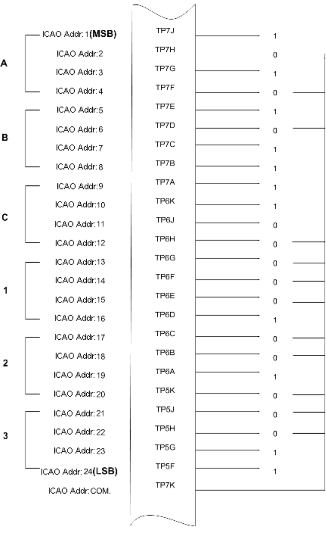
23-15-30 3-10
24 JUN 09
EMS SATCOM
SYSTEM DESCRIPTION, INSTALLATION, AND MAINTENANCE MANUAL
eNfusion™ HSD-440 High-speed Data Terminal
Figure 3-3 ICAO ID, Hex to Binary Conversion
A pin strapped to the same potential as TP7K (ICAO address common) is
considered as a logical 0, whereas an open circuit pin is considered as a logical 1.
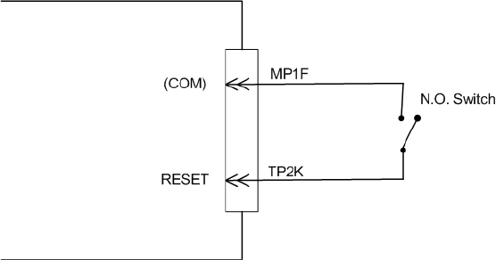
EMS SATCOM
SYSTEM DESCRIPTION, INSTALLATION, AND MAINTENANCE MANUAL
eNfusion™ HSD-440 High-speed Data Terminal
23-15-30 3-11
24 JUN 09
(f) Remote Status Panel (Optional)
An optional remote status panel may be installed when HSD-440 terminals are
located in inaccessible or remote locations. The installation of a remote status
panel is recommended as it provides visual indications of the power and faults
for each terminal.
A remote reset switch for HSD-440 terminals can also be installed and located
with the remote status panel. Figure 3-4 illustrates a typical wiring diagram for
the remote reset circuit.
1. Remote Reset Circuit Switch Requirements
HSD-440 terminals support the installation of a Remote Reset Switch circuit
as shown in Figure 3-4.
The HSD-440 terminal Remote Reset circuit requires less than 100 ohms
between TP1K (RESET) and MP1F(COM) to be asserted and greater than
10 kilohms to be de-asserted (includes all cable and switch contact
resistance).
Figure 3-4 Remote Reset Circuit Switch
2. Remote LED Driver Circuit Requirements
The circuit requirements for the HSD-440 terminal Remote Status LED drivers
are shown in Figure 3-5. Each LED driver circuit provides an open-drain
Field-Effect Transistor (FET) interface that has a maximum continuous
drain-to-source voltage of 35 V dc and drain-to-source current of 0.5 A dc.
These circuits are designed to sink current to ground only. Any external lamps
or LEDs connected to these driver circuits require the appropriate external
voltage and series impedance to be connected.
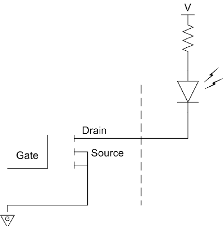
23-15-30 3-12
24 JUN 09
EMS SATCOM
SYSTEM DESCRIPTION, INSTALLATION, AND MAINTENANCE MANUAL
eNfusion™ HSD-440 High-speed Data Terminal
Figure 3-5 Remote LED Panel Circuit
(g) User Interfaces
To facilitate user access to the HSD-440 terminal interfaces, install the following
connectors in the appropriate cabin area.
1. ISDN Interface
Install an RJ45 connector in the cabin area for user connections to the ISDN
interface.
2. Ethernet Data Interface
Install one or two RJ45 interface connectors in the cabin area for user access
to the Ethernet interfaces.
3. RJ45 Connector Termination Details
Details relating to the RJ45 cable terminations required for both the ISDN
and/or 10BASE-T services are shown in Table 3-5 and Figure 3-6.
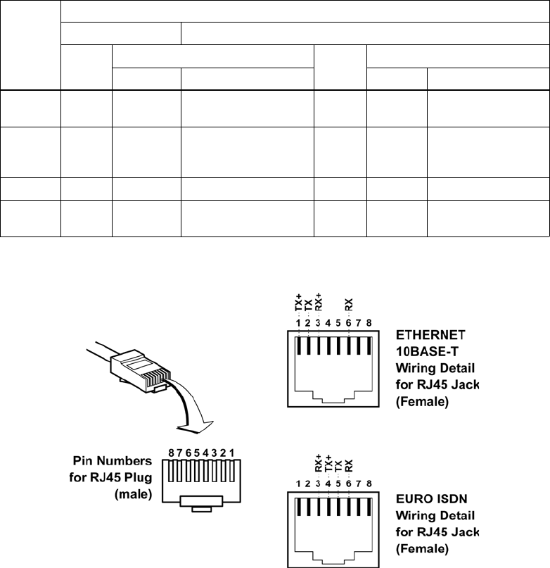
EMS SATCOM
SYSTEM DESCRIPTION, INSTALLATION, AND MAINTENANCE MANUAL
eNfusion™ HSD-440 High-speed Data Terminal
23-15-30 3-13
24 JUN 09
Figure 3-6 RJ45 Connector Terminator Details
Use LAN cables that meet flammability and TIA/EIA568-A CAT-5
requirements. Cables #922404 (4 conductor) and # 922408 (8 conductor), as
supplied by Electronics Cable Specialists, are acceptable. Equivalent
substitutions from other manufacturers may be used.
4. System Configuration Pin Strapping
The HSD-440 terminal adjusts its configuration according to the status of
several strap pins on the rear ARINC 600 connector.
Configuration pins are assigned based on system mode configuration
selection requirements, as shown in Table 3-6. Detailed pin assignment is
shown in Table 3-7.
Table 3-5 RJ45 Wiring Details
SIGNAL
Service
EURO ISDN ETHERNET 10BASE-T
PIN CABLE PIN CABLE
ECS OTHER ECS OTHER
RX+ 3White White/green 3White White/orange
stripe
RX- 6Blue Green 6Green Orange/white
stripe or solid
orange
TX+ 4White Blue 1White White/green stripe
TX- 5Orange White/blue 2Brown Green/white stripe
or solid Green
23-15-30 3-14
24 JUN 09
EMS SATCOM
SYSTEM DESCRIPTION, INSTALLATION, AND MAINTENANCE MANUAL
eNfusion™ HSD-440 High-speed Data Terminal
NOTE: The logic for the System Configuration pins is reverse to the logic
explained in ARINC 741 Characteristic Attachment 1-4, Note 19.
• Pins marked 0 are signaled by strapping to Address Common (TP7K).
• Pins marked 1 are signaled by an open circuit-no connection.
• Configurations resulting in all ones (1) are invalid.
5. System Mode Strap Pins Coding
The HSD-440 terminal must be externally strapped according to its intended
operational configuration mode. Table 3-7 illustrates the system pin strapping
for currently supported HSD-440 terminal operational modes and
configurations.
NOTE: The logic for the System Configuration pins is reverse to the logic
explained in ARINC 741 Characteristic Attachment 1-4, Note 19.
• Pins marked 0 are signaled by strapping to Address Common (TP7K).
• Pins marked 1 are signaled by an open circuit—no connection.
• Configurations resulting in all ones (1) are invalid.
(h) ARINC 429 IRS Bus Interface
In Stand-Alone Mode installations, navigational information is provided to the
HSD-440 terminal through the high-speed ARINC 429 IRS bus interface. Refer
to "System Description" on page 1-1 for more information. The IRS bus connects
through the top plug of the ARINC 600 connector to the HSD-440 terminal as
follows:
• IRS A to TP4J
• IRS B to TP4K
(i) Antenna Interface
The ARINC 741 antenna subsystem BSU/ACU is connected to the HSD-440
terminal as specified in Table 3-8.
Table 3-6 Configuration Pin Summary
Pin Number Name Function
TP4A to D System Config 1 to 4 System mode
Table 3-7 System Pin Strapping
Pin Status
System Mode TP4A TP4B TP4C TP4D
Invalid 1111
Stand-Alone 0101

EMS SATCOM
SYSTEM DESCRIPTION, INSTALLATION, AND MAINTENANCE MANUAL
eNfusion™ HSD-440 High-speed Data Terminal
23-15-30 3-15
24 JUN 09
(j) CMU Interface
Data rates, voltage thresholds, and electrical interface specifications are per
ARINC Specification 429. (741 p2-7 p4.7.2). The ARINC 600 wiring
interconnections for the HSD-440 terminal and each CMU are shown in
Table 3-9.
The bus speed can be either low or high. Both the transmit and receive ports of
the HSD-440 terminal ARINC 429 CMU ports operate together at either low
speed or high speed. Both CMUs therefore work at either low speed or high
speed, but not one at each speed. The speed is selectable by setting a flag in
Table 3-8 HSD-440 Terminal to BSU Interconnects
Signal Name Signal Source Signal Destination
HSD-440
Terminal Mechanical
HGA Phased-Array or
Conformal HGA
HPA MUTE A Port BSU-G TP3A
STBD BSU-G TP3C
HPA MUTE B Port BSU-H TP3B
STBD BSU-H TP3D
BSU BITE A BSU-W(G)* Port BSU-W TP2A
STBD BSU-W TP2C
BSU BITE B BSU-X(H) Port BSU-X TP2B
STBD BSU-X TP2D
Multi-Control A TP3E BSU-T(A)
Multi-Control B TP3F BSU-U(B)
*Letters in (brackets) represent EMS SATCOM AMT-50 BSU pin
designations
Top/Port (T/P): Refers to Mechanical (fin-mount) HGA Subsystem or Top Fuselage
mounted Phased Array or Beam Steered antenna
Port: Refers to Port side of Dual (side) Conformal-mount HGA subsystem
Starboard
(STBD): Refers to Starboard side of Dual (side) Conformal-mount HGA
subsystem
Table 3-9 CMU Interface Wiring
Pin Name To
TP1A CMU 1 Input A CMU 1 TP1A
TP1B CMU 1 Input B CMU 1 TP1B
TP1C CMU 1/2 Output A
TP1D CMU 1/2 Output B
MP1K CMU 2 Input B CMU 2 TP1A
MP2K CMU 2 Input A CMU 2 TP1B

23-15-30 3-16
24 JUN 09
EMS SATCOM
SYSTEM DESCRIPTION, INSTALLATION, AND MAINTENANCE MANUAL
eNfusion™ HSD-440 High-speed Data Terminal
the ORT (instead of setting a program pin on the HSD-440 A600 connector as
there are none available). If no information is available from the ORT, then the
bus speed shall default to low.
(k) MCDU Interface
Table 3-10 shows the strapping for the MCDU.
(l) Call Light Activation Strapping
Table 3-11 shows the configuration strapping for call light activation.
(m) Hookswitch Strapping
Table 3-12 shows the configuration strapping for the hookswitch method.
(n) Priority 4 Call Strapping
Table 3-13 shows the configuration strapping for priority 4 calls.
Table 3-10 MCDU Interface Wiring
Pin Name To
TP3E MCDU input A MCDU 2 ARINC Output A
TP3F MCDU input B MCDU 2 ARINC Output B
MP7G MCDU 1 input A MCDU ARINC Output A
MP7H MCDU 1 input B MCDU ARINC Output B
MP7J MCDU 1/2 output A To both MCDU 1 and 2 ARINC Input A
MP7K MCDU 1/2 output B To Both MCDU 1 and 2 ARINC Input B
Table 3-11 Call Light Activation Configuration Strapping
Pin Number Name Function
TP4E Call Light Activation Determines whether the call light illuminates on
call activation or initialization. Activation occurs
when the GES is responding to the call request,
and initialization occurs the moment the call is
placed. (1=Activation; 0=Initialization)
Table 3-12 Hookswitch Configuration Strapping
Pin Number Name Function
TP2G Hookswitch Method Determines Push To Talk (PTT) or Latched
Mode (0=Latched; 1=PTT)

EMS SATCOM
SYSTEM DESCRIPTION, INSTALLATION, AND MAINTENANCE MANUAL
eNfusion™ HSD-440 High-speed Data Terminal
23-15-30 3-17
24 JUN 09
(o) Chime and Light Strapping for Cockpit Voice
Table 3-14 shows the chime and light strapping for cockpit voice.
(3) Connection Details
"Stand-Alone Mode Connection Details" on page 3-18 provides all top, middle, and
bottom plug connection details for Stand-Alone Mode installations.
6. Installation and Engineering Diagrams
This section contains the Outline and Installation diagrams, and Interconnection and Contact
Assignment drawings for HSD-440 terminals.
A. Outline and Installation Diagrams
Figure 3-7, Figure 3-8, Figure 3-9, and Figure 3-10 illustrate the physical characteristics
of the HSD-440 terminal and provide installation data for the terminal.
All foldout pages are odd-numbered and not-backed for print production purposes.
B. Interconnection and Contact Assignment Drawings
Figure 3-11 illustrates the interconnection details for HSD-440 terminals.
Figure 3-12 provides the contact assignments for HSD-440 terminals.
All foldout pages are odd-numbered and not-backed for print production purposes.
Table 3-13 Priority 4 Call Configuration Strapping
Pin Number Name Function
TP4F Inhibit Priority 4 Calls Determines whether priority 4 calls are
inhibited. When these calls are inhibited,
incoming calls at priority 4 are not allowed, and
outgoing priority 4 calls are elevated to the next
priority and then placed. (1=Uninhibited;
0=Inhibited)
Table 3-14 Chime and Light Strapping for Cockpit Voice
TP4G TP4H Lights Chime
Strapped Strapped Spare
Strapped Open Steady Multi-stroke (chime sounds every
0.5 to 1 second)
Open Strapped Flashing Single-stroke (chime sounds
once)
Open Open Steady Single-stroke

23-15-30 3-18
24 JUN 09
EMS SATCOM
SYSTEM DESCRIPTION, INSTALLATION, AND MAINTENANCE MANUAL
eNfusion™ HSD-440 High-speed Data Terminal
7. Connection Details
This section includes connection details for the HSD-440 terminal operating in Stand-Alone
Mode.
A. Stand-Alone Mode Connection Details
Table 3-15, Table 3-16, and Table 3-17 show the top, middle, and bottom plug connection
details for HSD-440 terminals operating in Stand-Alone Mode.
Table 3-15 ARINC 600 Top Plug Connection Details
I/O From
Top
Plug
Signal Name To Description
I1A CMU 1 Input A CMU 1 TP1A CMU 1 RX A
I1B CMU 1 Input B CMU 1 TP1B CMU 1 RX B
O1C CMU 1/2 Output A CMU
1 and 2 Tx A
O1D CMU 1/2 Output BCMU
1 and 2 Tx B
I1E ARINC 615 Input A ARINC 615 Data Loader
I1F ARINC 615 Input B
O1G ARINC 615 Output A
O1H ARINC 615 Output B
I1J ARINC 615 Link A
O1K ARINC 615 Link B
(GND)
I2A BSU Top/Port BITE A
(See Note 1)
Mech. Steered Antenna
(MA): BSU, Pin G or W
or Other Antenna (OA):
BSU, PORT-W and
Starboard-P
ARINC Tx-HI BITE from
BSU
I2B BSU Top/Port BITE B MA: BSU, Pin H or X, or
OA: BSU, PORT-X and
STBD-R
ARINC Tx-LO BITE
from BSU
I2C BSU Starboard (STBD)
BITE A MA: Not required
OA: BSU, PORT-P and
STBD-W
ARINC Tx-HI BITE from
BSU
I2D BSU STBD BITE B MA: Not required
OA: BSU, PORT-R and
STBD-X
ARINC Tx-LO BITE
from BSU
O2E CMC Output A CMC
O2F CMC Output B CMC
I2G Hookswitch method
I2H CMC Input A
I2J CMC Input B

EMS SATCOM
SYSTEM DESCRIPTION, INSTALLATION, AND MAINTENANCE MANUAL
eNfusion™ HSD-440 High-speed Data Terminal
23-15-30 3-19
24 JUN 09
I3A Top/Port HPA MUTE A MA: Not required
OA: BSU, PORT-G HPA Mute-A, Port BSU
I2K Remote Reset Normally open
momentary switch-open
side.
(Closed side to MP1F)
Remote System Reset
I3A Top/Port HPA MUTE A MA: Not required
OA: BSU, PORT-H HPA Mute-A, Port BSU
I3B Top/Port HPA MUTE B MA: Not required
OA: BSU, PORT-H HPA Mute-B, Port BSU
I3C STBD HPA MUTE A MA: Not required
OA: BSU, STBD G HPA Mute-A, STBD
BSU
I3D STBD HPA MUTE B MA: Not required
OA: BSU, STBD-H HPA Mute-B, STBD
BSU
O3E Multi-Control A MA: BSU, Pin A or T, or
OA: BSU, PORT-T and
STBD-T
Multi-Control-HI to
HSD-440 terminal and
antenna subsystem
O3F Multi-Control B MA: BSU, Pin B or U, or
OA: BSU, PORT-U and
STBD-U
Multi-Control-LO to
HSD-440 terminal and
antenna subsystem
I3G WOW 1 TP3G Weight On Wheel, as
defined in Note 40 of
ARINC 741, Part 1.
Refer to Section 8.D
WOW Pin Wiring
I3J WOW Program Select TP3J
I3K WOW 2 TP3K
I4A,
4B,
4C,
4D
System Config 1 to 4 4A and 4C=0 (TP7K
common), 4B and
4D=1(Open)
Stand-Alone Mode
I4E Call light activation
I4F Priority 4 Calls Inhibit Priority 4 calls
to/from Cockpit. All
priority 4 A to G calls will
have priority elevated to
3.
I4G Chime/light option MS
I4H Chime/light option LS
I4J IRS-A Aircraft main IRS IRS 429 data, Rx HI
I4K IRS-B Aircraft main IRS IRS 429 data, Rx LO
I5A SDI 1 Not connected
I5B SDI 2 SDI common (TP5D) HPA Select Code for
HGA
I5C Spare 1 Input A
I5D SDI Common SDI 2 (TP5B) SDI Common
Table 3-15 ARINC 600 Top Plug Connection Details (Continued)
I/O From
Top
Plug
Signal Name To Description

23-15-30 3-20
24 JUN 09
EMS SATCOM
SYSTEM DESCRIPTION, INSTALLATION, AND MAINTENANCE MANUAL
eNfusion™ HSD-440 High-speed Data Terminal
I5E Spare 1 Input B
I5F ICAO Address, BIT 24 1 = no connection
0 = common (TP7K)
I5G ICAO Address, BIT 23
I5H ICAO Address, BIT 22
I5J ICAO Address, BIT 21
I5K ICAO Address, BIT 20
I6A ICAO Address, BIT 19
I6B ICAO Address, BIT 18
I6C ICAO Address, BIT 17
I6D ICAO Address, BIT 16
I6E ICAO Address, BIT 15
I6F ICAO Address, BIT 14
I6G ICAO Address, BIT 13
I6H ICAO Address, BIT 12
I6J ICAO Address, BIT 11
I6K ICAO Address, BIT 10
I7A ICAO Address, BIT 9
I7B ICAO Address, BIT 8
I7C ICAO Address, BIT 7
I7D ICAO Address, BIT 6
I7E ICAO Address, BIT 5
I7F ICAO Address, BIT 4
I7G ICAO Address, BIT 3
I7H ICAO Address, BIT 2
I7J ICAO Address, BIT 1
(MSB)
I7K ICAO Address,
Common Common GND
connection for system
and I/O configuration
and ICAO ID
Table 3-15 ARINC 600 Top Plug Connection Details (Continued)
I/O From
Top
Plug
Signal Name To Description

EMS SATCOM
SYSTEM DESCRIPTION, INSTALLATION, AND MAINTENANCE MANUAL
eNfusion™ HSD-440 High-speed Data Terminal
23-15-30 3-21
24 JUN 09
Table 3-16 ARINC 600 Middle Plug Connection Details
I/O From
Middle
Plug
Signal Name To Description
O1A Power LED
Output 1 Remote status panel HSD-440
terminal-Power On
(Optional)
O1B Fault LED
Output 2 Remote status panel HSD-440 terminal-Fault
(Optional)
1C Channel
Available
1D Switch HI
current from
chime
1E Switch LO
current to
chime
O1F Discrete
Common Remote status panel Discrete Common
O1G Maint Port Tx Maint Port serial data, DB9S-2 Maintenance computer
(laptop/PC), for Remote
access
I1H Maint Port Rx Maint Port serial data, DB9S-3
I/O 1J Maint Port
Signal Ground Maint Port serial data, DB9S-5
I1K CMU 2 Input A CMU 2 TP1A CMU 2 RX A
O2A Data I/O Tx No connection
I2B Data I/O Rx No connection
O2C SDU data SCM A
O2D SDU data SCM B
I2E SCM data SDU A
I2F SCM data SDU B
O2G SCM power
+12 V SCM
O2H SCM power
return 0 V SCM
2J Data I/O
Ground No connection
I2K CMU 2 Input B CMU 2 TP1B CMU 2 RX B
O3A Call light 1 Audio Control Panel
I3B Mic on 1 Audio Management System
I3C Chime light
inhibit Audio Control Panel
I3D Place/end 1 Audio Management System
I3E MCDU 2 input
AMCDU 2 J4-27 MCDU 2 RX A

23-15-30 3-22
24 JUN 09
EMS SATCOM
SYSTEM DESCRIPTION, INSTALLATION, AND MAINTENANCE MANUAL
eNfusion™ HSD-440 High-speed Data Terminal
I3F MCDU 2 input
BMCDU 2 J4-28 MCDU 2 RX B
O3G Call light 2 Future
I3H Mic on 2 Future
I3J Go-ahead /
Chime reset Audio Control Panel
I3K Place/End 2 Future
I/O 4A POTS 1 TIP 2-wire Analog Phone TIP
(RJ-11, Pin 4) POTS Line 1
I/O 4B POTS 1 RING 2-wire Analog Phone RING
(RJ-11, Pin 3)
I/O 4C POTS 2 TIP 2-wire Analog Phone TIP
(RJ-11, Pin 4) POTS Line 2
I/O 4D POTS 2 RING 2-wire Analog Phone RING
(RJ-11, Pin 3)
I4E Input audio 1 HI Cockpit Headset Microphone
HI Cockpit Voice
Microphone
I4F Input audio 1
HLO Cockpit Headset Microphone
LO
I/O 4G to 4K Reserved
5A CEPT-E1 RX+ Future
5B CEPT-E1 RX-
5C CEPT-E1 TX+
5D CEPT-E1 TX-
O5E Audio 1 HI Cockpit Headset Speaker HI Cockpit Voice Speaker
O5F Audio 1 LO Cockpit Headset Speaker LO
I/O 5G to 5K Reserved
I6A ISDN Rx+ ISDN, RJ45-3 User data, ISDN-1
Refer to "User
Interfaces" on page 3-12
I6B ISDN Rx - ISDN, RJ45-6
O6C ISDN Tx+ ISDN, RJ45-4
O6D ISDN Tx- ISDN, RJ45-5
I6E Audio 2 HI Future
I6F Audio 2 LO Future
Table 3-16 ARINC 600 Middle Plug Connection Details (Continued)
I/O From
Middle
Plug
Signal Name To Description

EMS SATCOM
SYSTEM DESCRIPTION, INSTALLATION, AND MAINTENANCE MANUAL
eNfusion™ HSD-440 High-speed Data Terminal
23-15-30 3-23
24 JUN 09
O6G 10BASE-T Tx+ Ethernet 10BASE-T
RJ45, Pin 1 Port 2
User data
Ethernet 10BASE-T
O6H 10BASE-T Tx- Ethernet 10BASE-T
RJ45, Pin 2
I6J 10BASE-T Rx+ Ethernet 10BASE-T
RJ45, Pin 3
I6K 10BASE-T Rx- Ethernet 10BASE-T
RJ45, Pin 6
O7A 10BASE-T Tx+ Ethernet 10BASE-T, RJ45-1 Port 1
User data
Ethernet 10BASE-T
O7B 10BASE-T Tx- Ethernet 10BASE-T, RJ45-2
I7C 10BASE-T Rx+ Ethernet 10BASE-T, RJ45-3
I7D 10BASE-T Rx- Ethernet 10BASE-T, RJ45-6
I/O 7E to 7K Reserved
OC1 RF Tx Output Antenna subsystem-DLNA or
HPR-J Coaxial cable, RF
Transmit
Table 3-16 ARINC 600 Middle Plug Connection Details (Continued)
I/O From
Middle
Plug
Signal Name To Description
Table 3-17 ARINC 600 Bottom Plug Connection Details
I/O From
Bottom
Plug
Signal Name To Description
IBP2 +28 V dc HOT Aircraft Power Source, HOT +28 V dc supply
IBP3 +28 V dc return
GND Aircraft Power Source, return
IBP8 Chassis GND Aircraft Ground Aircraft Chassis
Ground
IBP1 115 V ac HOT Aircraft Power Source, HOT 115 V ac 400 Hz
supply
IBP7 115 V ac COLD Aircraft Power Source, COLD
IBP12 RF Rx Input Antenna subsystem-DLNA Coaxial cable, RF
Receive
23-15-30 3-24
24 JUN 09
EMS SATCOM
SYSTEM DESCRIPTION, INSTALLATION, AND MAINTENANCE MANUAL
eNfusion™ HSD-440 High-speed Data Terminal
Blank Page
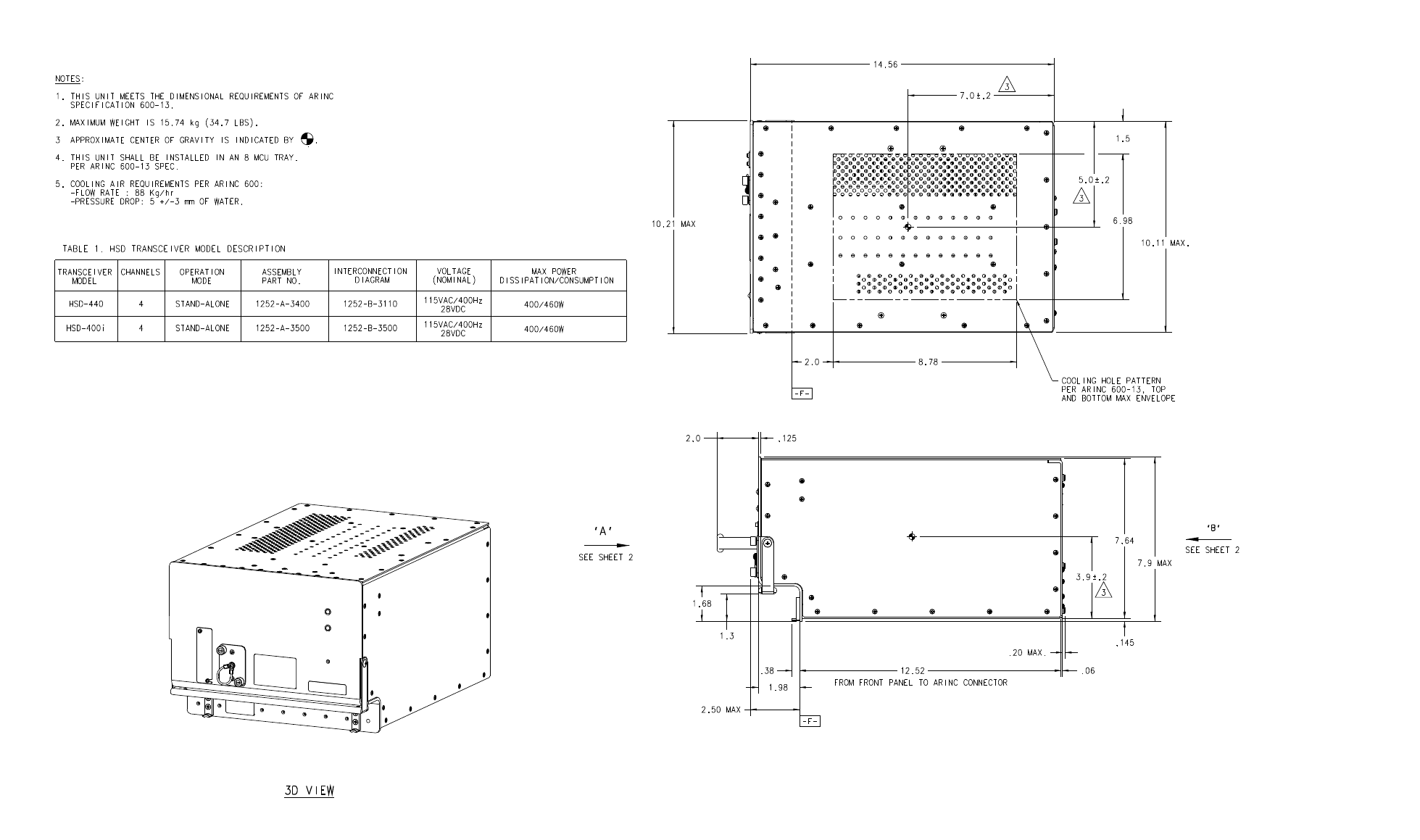
EMS SATCOM
SYSTEM DESCRIPTION, INSTALLATION, AND MAINTENANCE MANUAL
eNfusion™ HSD-440 High-speed Data Terminal
23-15-30 3-25
16 JUN 09
Figure 3-7 (Sheet 1). HSD-440 Terminal Outline and Installation Diagram
(1252-E-3400, Rev B)
Blank Page
EMS SATCOM
SYSTEM DESCRIPTION, INSTALLATION, AND MAINTENANCE MANUAL
eNfusion™ HSD-440 High-speed Data Terminal
23-15-30 3-26
16 JUN 09
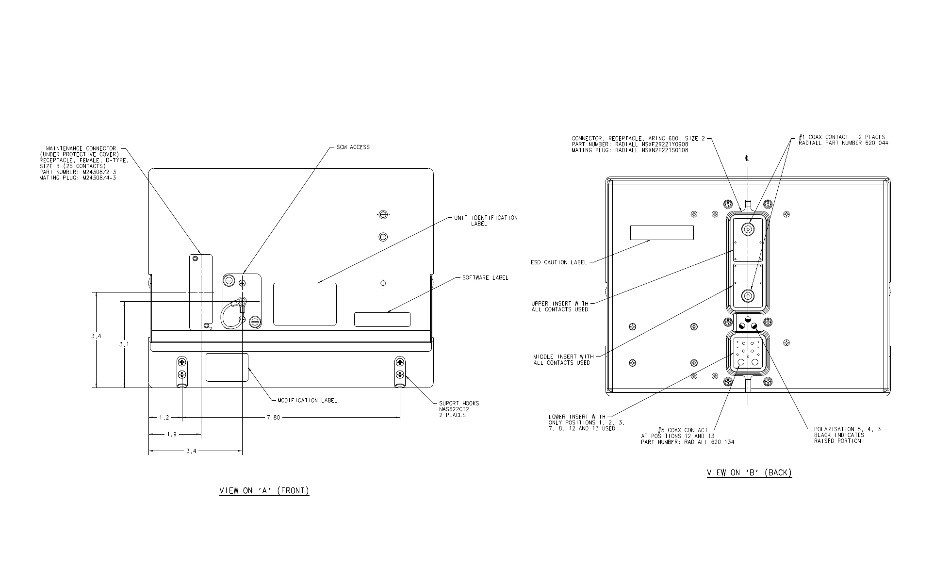
EMS SATCOM
SYSTEM DESCRIPTION, INSTALLATION, AND MAINTENANCE MANUAL
eNfusion™ HSD-440 High-speed Data Terminal
23-15-30 3-27
16 JUN 09
Figure 3-8 (Sheet 2). HSD-440 Terminal Outline and Installation Diagram
(1252-E-3400, Rev B)
Blank Page
EMS SATCOM
SYSTEM DESCRIPTION, INSTALLATION, AND MAINTENANCE MANUAL
eNfusion™ HSD-440 High-speed Data Terminal
23-15-30 3-28
16 JUN 09
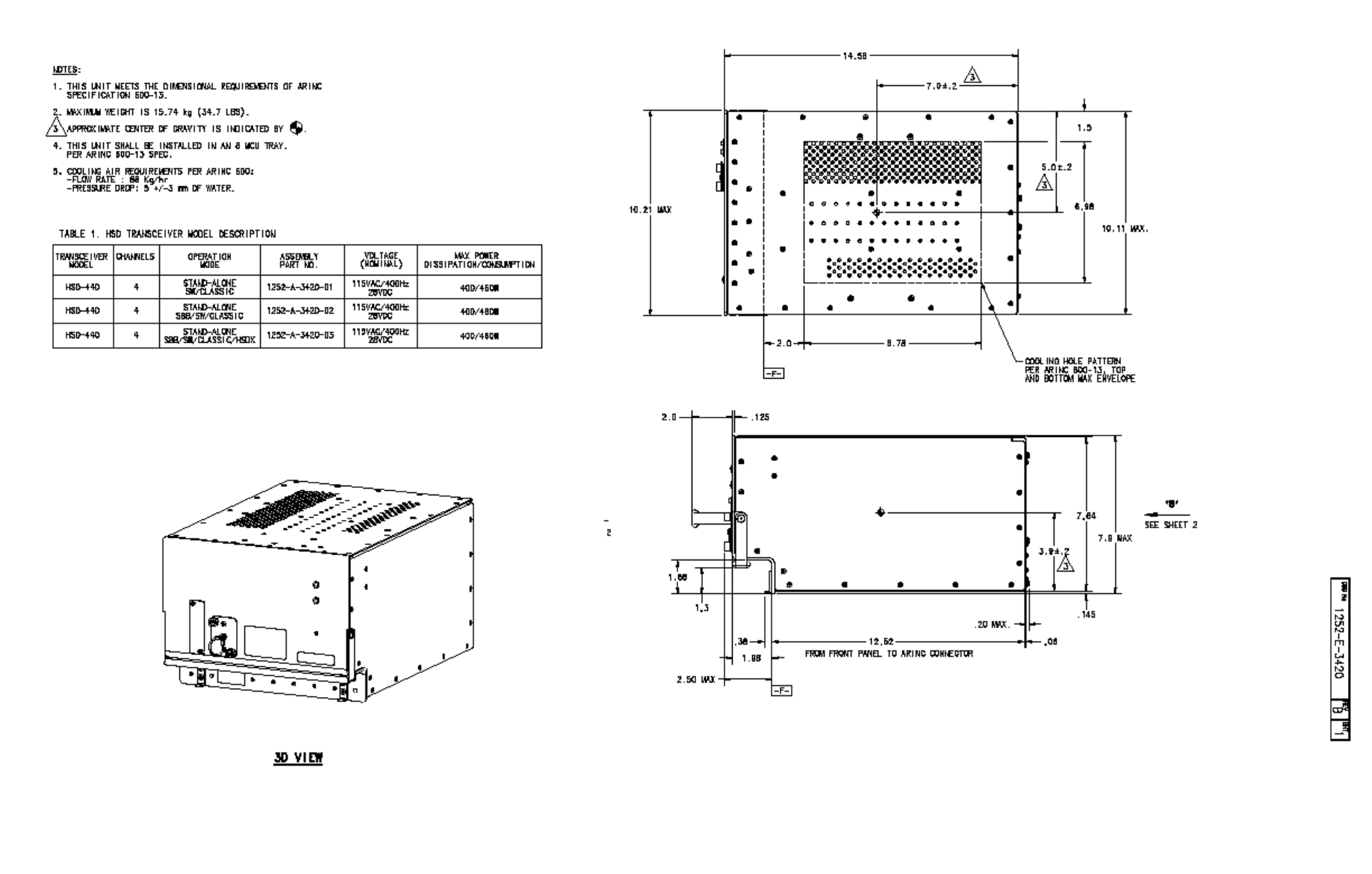
EMS SATCOM
SYSTEM DESCRIPTION, INSTALLATION, AND MAINTENANCE MANUAL
eNfusion™ HSD-440 High-speed Data Terminal
23-15-30 3-29
16 JUN 09
Figure 3-9 (Sheet 1). HSD-440 Terminal Outline and Installation Diagram
(1252-E-3420, Rev B)
Blank Page
EMS SATCOM
SYSTEM DESCRIPTION, INSTALLATION, AND MAINTENANCE MANUAL
eNfusion™ HSD-440 High-speed Data Terminal
23-15-30 3-30
16 JUN 09
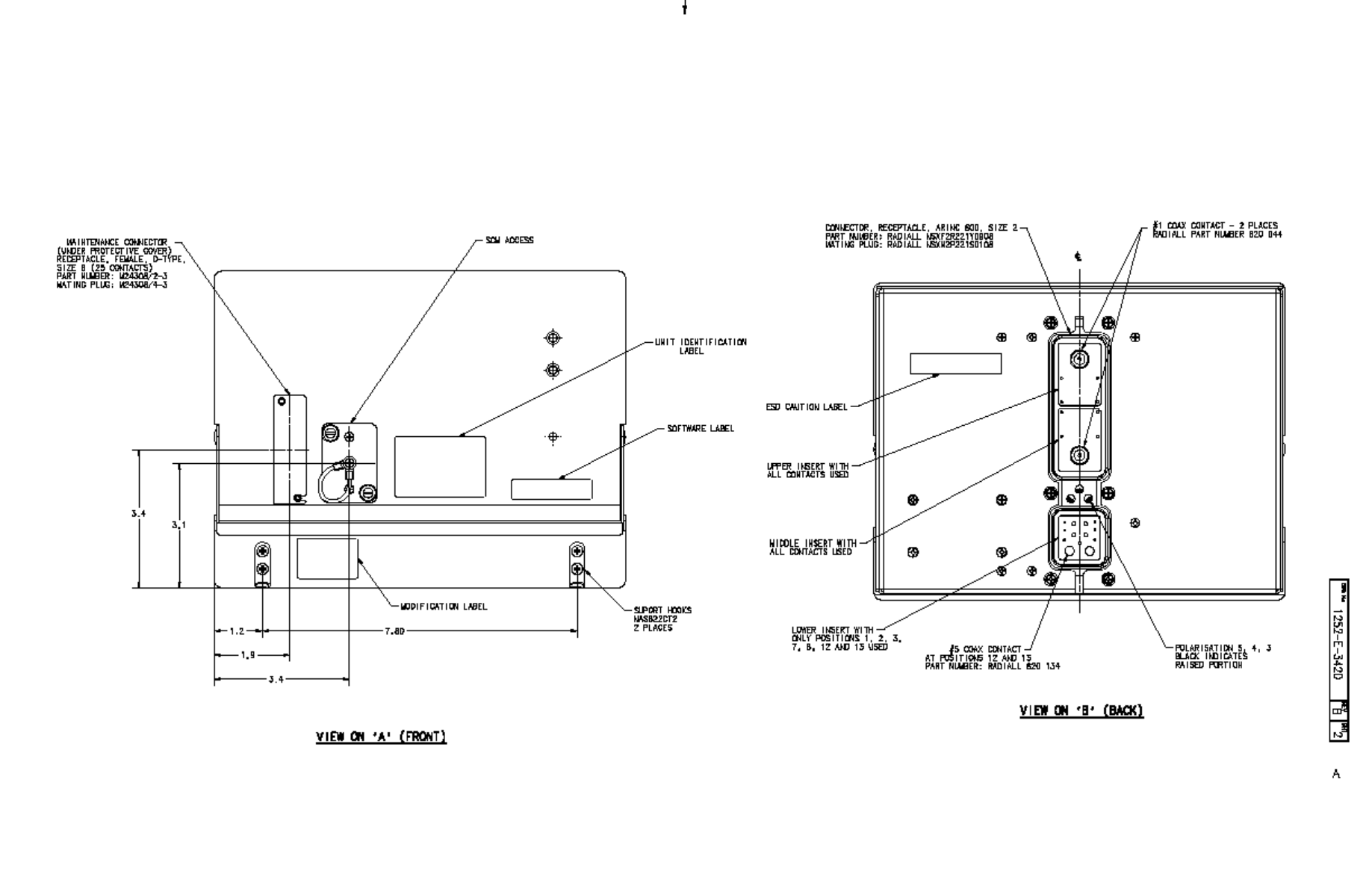
EMS SATCOM
SYSTEM DESCRIPTION, INSTALLATION, AND MAINTENANCE MANUAL
eNfusion™ HSD-440 High-speed Data Terminal
23-15-30 3-31
16 JUN 09
Figure 3-10 (Sheet 2). HSD-440 Terminal Outline and Installation Diagram
(1252-E-3420, Rev B)
Blank Page
EMS SATCOM
SYSTEM DESCRIPTION, INSTALLATION, AND MAINTENANCE MANUAL
eNfusion™ HSD-440 High-speed Data Terminal
23-15-30 3-32
16 JUN 09
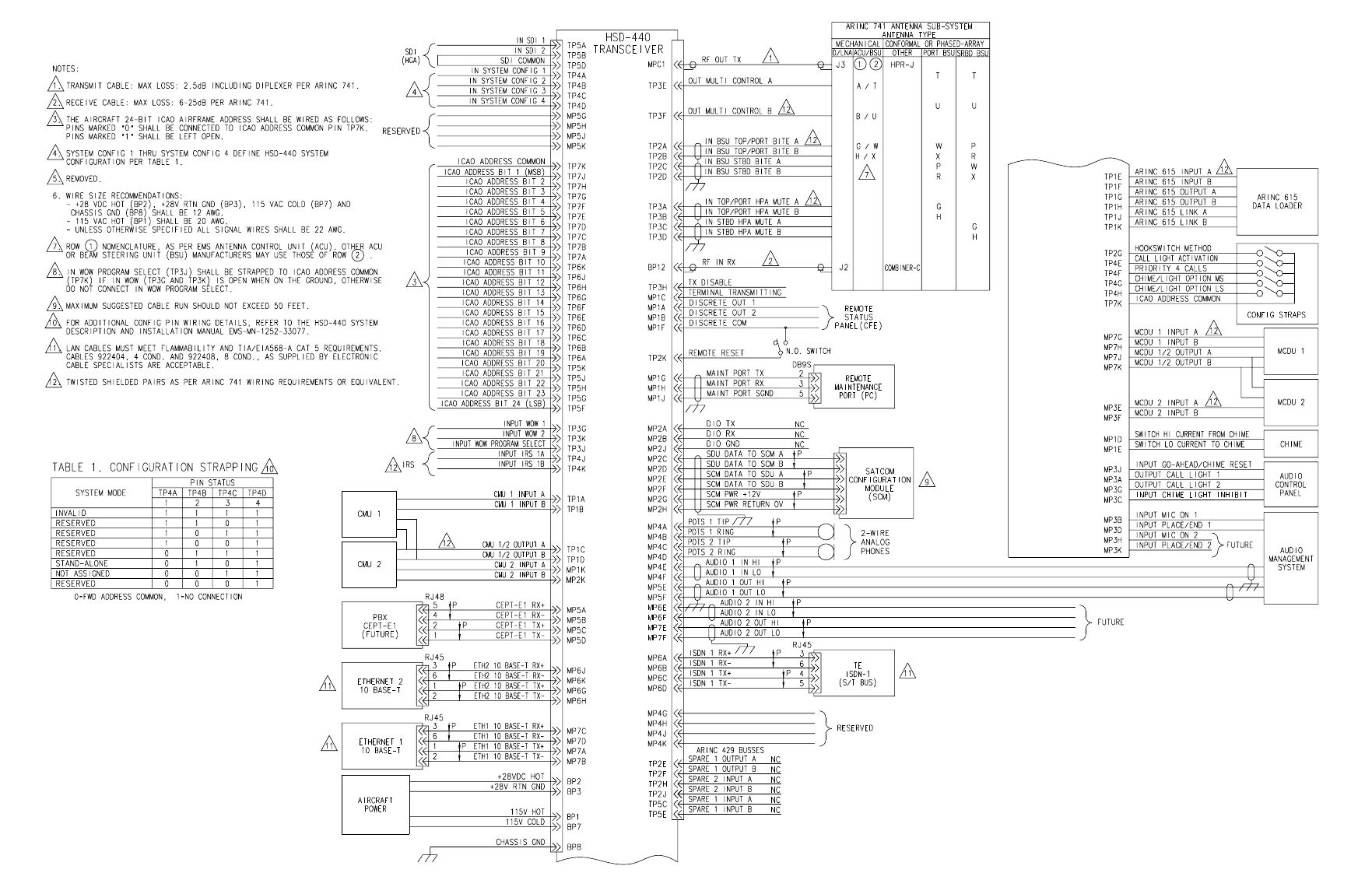
EMS SATCOM
SYSTEM DESCRIPTION, INSTALLATION, AND MAINTENANCE MANUAL
eNfusion™ HSD-440 High-speed Data Terminal
23-15-30 3-33
16 JUN 09
Figure 3-11 (Sheet 1). HSD-440 Terminal Interconnection and Contact Assignment Drawing
(1252-B-3110, Rev D)
Blank Page
EMS SATCOM
SYSTEM DESCRIPTION, INSTALLATION, AND MAINTENANCE MANUAL
eNfusion™ HSD-440 High-speed Data Terminal
23-15-30 3-34
16 JUN 09
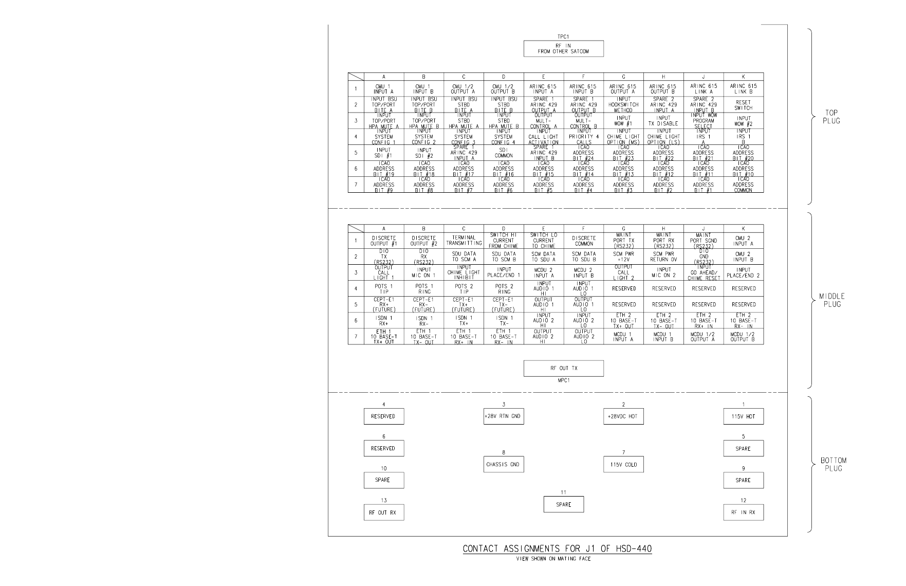
EMS SATCOM
SYSTEM DESCRIPTION, INSTALLATION, AND MAINTENANCE MANUAL
eNfusion™ HSD-440 High-speed Data Terminal
23-15-30 3-35
16 JUN 09
Figure 3-12. (Sheet 2). HSD-440 Terminal Interconnection and Contact Assignment Drawing
(1252-B-3110, Rev D)
Blank Page
EMS SATCOM
SYSTEM DESCRIPTION, INSTALLATION, AND MAINTENANCE MANUAL
eNfusion™ HSD-440 High-speed Data Terminal
23-15-30 3-36
16 JUN 09

EMS SATCOM
SYSTEM DESCRIPTION, INSTALLATION, AND MAINTENANCE MANUAL
eNfusion™ HSD-440 High-speed Data Terminal
23-15-30 4-1
24 JUN 09
TEST AND FAULT ISOLATION
This section provides the information required to determine the operational readiness of the
HSD-440 terminals and aid service personnel in diagnosing system faults, including the
following sections:
•Operational and Diagnostic Testing
•Troubleshooting and Fault Isolation
•Adjustment/Alignment Procedures
•Modification History
The operational and diagnostic tests described in this section require using the HSD-440
terminals built-in diagnostic tool referred to as the HSD-440 terminal MPU. This section
provides detailed descriptions of the HSD-440 terminal MPU menus, reports, and basic user
instructions. See "Cabling Notes" on page 4-3 for maintenance port cabling notes.
NOTE: Depending on the version of software installed, the MPU report and menu screens
displayed may differ from those shown as examples in this manual.
1. Operational and Diagnostic Testing
A. General
Usually, terminals require testing for one of the following reasons:
• To verify the operational readiness of the terminal during and after installation on an
aircraft
• To verify that a fault exists and produce system reports for troubleshooting purposes
• To verify the operational readiness of repaired LRUs during re-installation on an
aircraft
This section includes test and fault isolation procedures for the HSD-440 terminals. All
test and load procedures require the HSD-440 terminal MPU, which is accessed by
connecting to the maintenance port of the terminal.
B. Test and Fault Isolation Equipment Requirements
Table 4-1 lists the equipment required to access the HSD-440 terminal MPU and perform
operational and diagnostic testing and software loads on the HSD-440 terminal.

23-15-30 4-2
24 JUN 09
EMS SATCOM
SYSTEM DESCRIPTION, INSTALLATION, AND MAINTENANCE MANUAL
eNfusion™ HSD-440 High-speed Data Terminal
Table 4-2 lists the optional equipment or information that, although not required, may
increase test efficiency or allow for optional diagnostic procedures. Equivalent
substitutions may be used.
C. Terminal MPU
This section describes the HSD-440 terminal MPU and provides the connection and
cabling details required to access and use the program.
(1) General Overview
The MPU, built into the HSD-440 terminal's operational software, provides a system
interface for fault isolation and diagnostic procedures. Connection to this program is
made through the RS-232 maintenance port interface.
To use the HSD-440 terminal MPU, an RS-232, VT-100 terminal (PC or laptop
operating a terminal emulation program) must be connected to the HSD-440 terminal.
The maintenance port on the front panel of HSD-440 terminals provides a direct
connection to the HSD-440 terminal MPU using a DB25 connector. Optionally, remote
cabin access is possible using a DB9 connector via the ARINC 600 connector.
Table 4-1 List of Required Test Equipment
Item Equipment Specification Quantity
Computer Standard VT-100 386 CPU, 20 MHz or
higher 1
VT-100 terminal
emulation program HyperTerminal©,
ProComm Plus©, or
equivalent
Serial communication program
using an RS-232 port 1
Cable, maintenance port
interface cable Special
See "Connection
Requirements" on
page 4-3
Remote access maximum cable
length 25 ft. (From ARINC 600
connector to DB9 breakout
connector)
Front Panel access maximum
cable length 50 ft.
1
Multimeter Standard – 1
General purpose toolset Standard – 1
Table 4-2 List of Optional Test Equipment
Item Equipment Specification Quantity
Service Provider Information
Package Special Inmarsat service provider 1
Internet access Standard Inmarsat Swift64 high-speed
data 1
Time Domain Refectometer Standard – 1
EMS SATCOM
SYSTEM DESCRIPTION, INSTALLATION, AND MAINTENANCE MANUAL
eNfusion™ HSD-440 High-speed Data Terminal
23-15-30 4-3
24 JUN 09
(2) Connection Requirements
This section describes specific cabling requirements needed to connect to and use
the HSD-440 terminal MPU.
(a) Cabling Notes
The HSD-440 terminals provide two options for physical connection to the
HSD-440 terminal maintenance port and MPU: direct connection and remote
connection.
Table 4-3, Table 4-4, Figure 4-1, and Figure 4-2 provide cabling details for the
HSD-440 terminal for both direct and remote connection types. Select one of
these connection options to access the HSD-440 terminal MPU.
NOTE: The direct and remote connection points to the HSD-440 terminal
maintenance port cannot be used simultaneously.
(b) Maintenance Port Cable Assembly
HSD-440 terminal maintenance cable connections may vary in length, type of
connection used, and connector pin callouts, depending on the access point
used.
The cable assembly for HSD-440 terminals assumes that the computer's COM
port interface is a 9-Pin, D-Sub connector (DB9). Cable assembly details for
HSD-440 terminals are presented in Figure 4-1 and Figure 4-2.
NOTE: The maximum cable length, shown in Figure 4-1 and Figure 4-2,
assumes that the length is measured from the ARINC 600 connector to
the DB9 breakout connector.
Table 4-3 Remote Connection Cabling
Remote Access
Pin Definition ARINC
Connector
(Rear) Remote (DB9)
Cable
(See Figure 4-1)
Computer
(DB9P)
Maint Port SGND (MP1J) 5 5
Maint Port Rx (MP1H) 3 3
Maint Port Tx (MP1G) 2 2
Table 4-4 Direct Connection Cabling
Direct Connection
Pin Definition Front Panel
Maintenance
Cable
Connector
(DB25P) Cable
(See Figure 4-2)
Computer
(DB9P)
Maint Port SGND 10 10 5
Maint Port Rx 12 12 3
Maint Port Tx 11 11 2
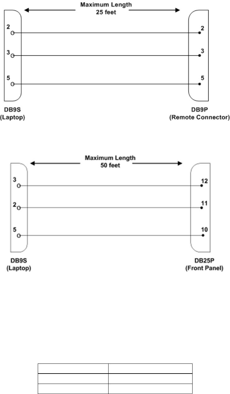
23-15-30 4-4
24 JUN 09
EMS SATCOM
SYSTEM DESCRIPTION, INSTALLATION, AND MAINTENANCE MANUAL
eNfusion™ HSD-440 High-speed Data Terminal
Figure 4-1 Remote Connection, Maintenance Cable
Figure 4-2 Direct Connection, Maintenance Cable
(c) Interface Requirements
A standard VT100 compatible terminal running an emulator program (such as
HyperTerminal, ProComm Plus, or similar) provides the user interface to the
HSD-440 terminal MPU. The RS-232 terminal connection settings for HSD-440
terminal maintenance ports are listed in Table 4-5.
Table 4-5 Terminal Connection Settings
Parameter Setting
Character Format ASCII
Baud Rate 19200 bps

EMS SATCOM
SYSTEM DESCRIPTION, INSTALLATION, AND MAINTENANCE MANUAL
eNfusion™ HSD-440 High-speed Data Terminal
23-15-30 4-5
24 JUN 09
(3) Accessing the MPU
Access to the MPU menus is password protected. Each password permits access to
a different level of the program.
This document describes End User and Field Representative access levels for
operational testing and verification, software updates, and the basic system
monitoring and troubleshooting procedures provided in this manual.
(a) Level 1 End User Access—Password: menu
This limited-access level is for anyone without technical training on the product.
It provides read-only access to help users diagnose problems with the assistance
of product support personnel.
(b) Level 2 Field Representative Access—Password: maint
This level is for trained original equipment manufacturer (OEM) installers and
product support personnel. This access level supports read and limited write
capabilities. Users are able to disable, mask, or clear faults, change satellite or
LES preferences, view and modify certain EEPROM parameters, and perform
other maintenance or upgrade functions.
(4) Using the Terminal MPU
This section describes the basic procedures for using and navigating the HSD-440
terminal MPU.
(a) Entering Passwords
• For untrained users, use Level 1 access: type menu.
• For trained technicians and product support personnel, use Level 2 access:
type maint.
NOTE: The password does not appear on the screen when you type it.
(b) Navigating the Terminal MPU
• To scroll through the available menus, press CTRL+N.
• To go to the previous menu, press CTRL+O.
• To refresh the menu screen or exit from a Reports Menu, press ESC.
(c) Selecting Menu Items
To enable test or data entry functions, press the letter associated with the menu
items. When a menu item is selected, the application may prompt you for
additional inputs or selections.
No. of bits 8
Parity None
Stop bits 1
Flow Control None
Table 4-5 Terminal Connection Settings (Continued)
Parameter Setting

23-15-30 4-6
24 JUN 09
EMS SATCOM
SYSTEM DESCRIPTION, INSTALLATION, AND MAINTENANCE MANUAL
eNfusion™ HSD-440 High-speed Data Terminal
(d) Selecting Reports
The reports available through the MPU enable users to view information about
the configuration and status of the HSD-440 terminal. This information is used
to troubleshoot the communication system on the aircraft.
1. To open the list of possible system reports, press EQUAL SIGN.
A list of reports appears. Active reports show as toggled on. Inactive reports
show as toggled off.
2. To activate a report, type the report number, and then press ENTER.
NOTE: Multiple reports can be activated at the same time; type and enter
each report number separately.
3. To turn off individual, active reports, type the report number you want to
toggle off, and then press ENTER.
4. To turn off all active reports, press EQUAL SIGN, and then press X.
(5) Menu Item Descriptions
This section provides a brief description of the Level 2, MPU menu items used for test
and fault isolation procedures.
Although this section only provides illustrations and descriptions for Level 2 access,
all Level 1 access menu items are covered. (All Level 1 menus are included in Level
2 Menus.)
In active HSD-440 terminals, menu screens display the firmware version.
NOTE: Depending on the version of software installed and the system configuration,
the menu and reports available to users may differ slightly from the
illustrations shown and described in this document.
(a) Menu 1
Figure 4-3 shows the HSD-440 terminal MPU Menu 1 screen display. Table 4-6
describes the items available in Menu 1.
Figure 4-3 Menu 1 Screen Display
MENU 1 FIRMWARE Vx.x
X override forward id/ICAO address L test LEDs
Y explain error status U list event log (hex)
F print equipment stats M clear equipment stats
<CTRL> N next menu <CTRL> O previous menu = select reports
EMS SATCOM
SYSTEM DESCRIPTION, INSTALLATION, AND MAINTENANCE MANUAL
eNfusion™ HSD-440 High-speed Data Terminal
23-15-30 4-7
24 JUN 09
(b) Menu 2
Figure 4-4 shows the HSD-440 terminal MPU Menu 2 screen display. Table 4-7
describes the items available in Menu 2.
Figure 4-4 Menu 2 Screen Display
Table 4-6 Menu 1 Item Descriptions
Menu Item Description
X: override forward
id/ICAO address Used in testing and fault isolation.
Enter a test or alternate FWD ID or ICAO ID to use during fault
isolation procedures. Resetting the HSD-440 terminal or cycling
the power cancels this function.
Y: explain error status Reports error status when failure LED is illuminated.
F: print equipment
stats Prints a list of the current equipment statistics.
L: test LEDs Toggles the Power On (LED 1) and Fault (LED 2) LEDs on (A)
and off (D) or returns them to software control (X).
U: list event log Lists the current event log.
M: clear equipment
stats Resets the equipment statistics. (See Item F.)
MENU 2 FIRMWARE Vx.x
A set veh-relative azimuth E set veh-relative elevation
K desired az veh-rel velocity R resume automatic steering
T enter time of day N annotate log file
L re-enter logon password V get firmware versions
Z reset S set satellite longitude
<CTRL> N next menu <CTRL> O previous menu = select reports
Table 4-7 Menu 2 Item Descriptions
Menu Item Description
NOTE: Menu 2 selections E and K are used to manually input navigational data to point
the antenna to a preferred satellite location and/or peak for maximum signal
reception. These commands are typically used where no IRS data is available.
A: set veh-relative
azimuth Antenna azimuth pointing offset with reference to the front
centerline of the aircraft.
Offset value entered in degrees from 0 to 180, where a positive
entry is clockwise (cw) and a negative entry is
counterclockwise (ccw).

23-15-30 4-8
24 JUN 09
EMS SATCOM
SYSTEM DESCRIPTION, INSTALLATION, AND MAINTENANCE MANUAL
eNfusion™ HSD-440 High-speed Data Terminal
(c) Menu 3
Figure 4-5 shows the HSD-440 terminal MPU Menu 3 screen display. Table 4-8
describes the items available in Menu 3. Figure 4-6 shows the Menu 3, Item M:
Miscellaneous parameters screen display. Table 4-9 describes the items
available in Menu 3, Item M.
Figure 4-5 Menu 3 Screen Display
K: desired az veh-rel
velocity Activates continuous antenna azimuth sweep at a set
elevation, as entered with menu item E.
Azimuth sweep velocity entered as deg/sec value.
NOTE: When combined with a signal-monitoring reports
selection, sweep the antenna for maximum signal
strength to determine optimum location coordinates.
T: enter time of day Permits the entry of date and time for initial one-time setting of
the Real Time Clock.
L: re-enter logon
password Permits a user to enter a new access level password: menu
or maint.
Z: reset Enables a complete, soft reset of the LRU; once reset, the
menu access password must be re-entered.
E: set veh-relative
elevation Antenna elevation pointing offset with respect to the aircraft
horizontal rest position; i.e., assumed to have no pitch or roll
offset.
Offset value entered in degrees from 0 to 90.
R: resume automatic
steering Re-activates programmed automatic antenna-steering in both
azimuth and elevation.
N: annotate log file Allows for input of text into a log file.
This feature can be used to document information such as test
conditions, system or aircraft identification, or any pertinent
information for later review.
V: get firmware versions Displays the system Kernel and Application software versions,
and the channel card(s) and HPA firmware revisions.
S: set satellite longitude Sets the satellite longitude.
Table 4-7 Menu 2 Item Descriptions (Continued)
Menu Item Description
MENU 3 FIRMWARE Vx.x
L list EEPROM S list event log
C clear event log M misc. EEPROM parameter
F list call log G clear call log
O list ORT P ocean region parameter
I set all LES id's H list SCM/CP ORT
K set CP ORT parameter R copy CP ORT to SCM
<CTRL> N next menu <CTRL> O previous menu = select reports

EMS SATCOM
SYSTEM DESCRIPTION, INSTALLATION, AND MAINTENANCE MANUAL
eNfusion™ HSD-440 High-speed Data Terminal
23-15-30 4-9
24 JUN 09
Table 4-8 Menu 3 Item Descriptions
Menu Item Description
L: list EEPROM Displays a list of all system EEPROM parameters and their
corresponding values (this function is READ only).
Certain parameters are set using Menu 3, item M selection.
C: clear event log Clears all events and system fault codes stored in
non-volatile RAM.
F: list call log Displays call log files for HSD-440 terminal. When
selected, three options are available:
• To display complete list of all log files, press F.
• To list extended EIRP trace data, press X.
• To list all remaining entries, press PERIOD.
O: list ORT Displays all Data I/O parameters and Ocean Region
parameters.
I: set all LES id's Configures all ORs to the same LES access code.
K: set CP ORT parameter Sets user configurable ORT options in the control
processor ORT.
S: list event log Lists all events stored in non-volatile RAM.
When selected, several options are available:
•0 displays the most recent saved entry.
•S displays next most recent entry saved.
•PERIOD displays all remaining logged entries.
•1 displays special events (does not include ORR
entries).
M: misc. EEPROM
parameter Enables entry or entry changes to some EEPROM
parameters.
G: clear call log Clears call log files for HSD-440 terminal.
P: ocean region parameter Configures LES access codes for individual ORs.
H: list SCM/CP ORT Lists the values contained in either the SCM or the CP ORT.
R: copy CP ORT to SCM Copies values stored in the CP ORT to the SCM.

23-15-30 4-10
24 JUN 09
EMS SATCOM
SYSTEM DESCRIPTION, INSTALLATION, AND MAINTENANCE MANUAL
eNfusion™ HSD-440 High-speed Data Terminal
Figure 4-6 Menu 3—Item M: Miscellaneous Parameters
MISCELLANEOUS PARAMETERS
1 HPA-TO-ANTENNA TOTAL LOSS 20 CARD 1 IP ADDRESS
2 FORWARD ID 21 CARD 2 IP ADDRESS
3 GPS PROTECTION ALGORITHMS 22 TRANSMIT IF WEIGHT-ON-WHEELS
10 NUMBER OF CHANNEL CARDS 29 DEFAULT LATITUDE
11 FRONT PANEL LEDS ENABLED 30 DEFAULT LONGITUDE
14 MAINTENANCE PORT INVERSE VIDEO 31 OBEY OXCO STATUS
15 MAINTENANCE PORT DEGREES SYMBOL 42 HCM AERO/M4 PRIORITIZATION
16 TERMINAL CATEGORY 45 CATEGORY B LOWER FREQUENCY LIMIT
WHICH PARAMETER # <CTRL> N for next page ?
46 CATEGORY B UPPER FREQUENCY LIMIT 58 QUAL PA BACKOFF
51 SDU INPUT POWER OFFSET 59 CLASSIC AERO MANUAL BOOT
52 OUTPUT POWER COUPLING CONST 60 CH CARD GATEWAY ADDRESS
53 REFLECTED POWER COUPLING CONST 61 IMEI KEY
54 REFLECTED POWER SLOPE 62 SDU-TO-PA GAIN
55 REFLECTED POWER INTERCEPT 63 CARD 1 SUBNET ADDRESS
56 PSU CURRENT SLOPE 64 CARD 2 SUBNET ADDRESS
57 PSU CURRENT INTERCEPT 65 AIR/GROUND BEHAVIOUR
WHICH PARAMETER # <CTRL> N for next page ?
Table 4-9 Menu 3, Item M EEPROM Parameter Descriptions
Parameter
Number Parameter Name Description
1HPA-to-Antenna
Total Loss Defines transmit coaxial cable loss from the
HSD-440 terminal at MPC1 to the antenna, including
the DLNA loss—maximum is 2.5 dB (includes DLNA
loss of 0.8 dB).
2Forward ID Entry required as the ICAO address is strapped.
Refer to "Installation" on page 3-1 for strapping
details.
3GPS protection
algorithms Disables the GPS algorithms the HSD-440 terminal
uses to prevent calls from interfering with the GPS
navigational system on the aircraft.
10 Number of channel
cards Selects the number of channel cards for which the
system is configured.
11 Front panel LEDs
enabled Future consideration is provided for additional LEDs,
beyond the two currently activated—default is 2.
14 Maintenance port
inverse video Enables a selected report to be highlighted in Inverse
Video when it is activated—default is 1 (activated).

EMS SATCOM
SYSTEM DESCRIPTION, INSTALLATION, AND MAINTENANCE MANUAL
eNfusion™ HSD-440 High-speed Data Terminal
23-15-30 4-11
24 JUN 09
15 Maintenance port
degrees symbol Offers a choice of displaying the letter D or the
degree symbol ° when viewing the lat/long
information displayed in the Reports output:
• Select 0 to use the letter D; e.g., 180.0 D.
• Select 1 to use a degree symbol °; e.g., 180.0°.
16 Terminal category Offers an LRU configuration choice of the following:
• 1 for Stand-Alone
• 2 for HW Strapping
Default is 2 (where hardware is read on power-up).
20 Card 1 IP Address IP address of channel card 1.
22 Transmit if
Weight-on-Wheels Allows the system to transmit when it is on the
ground.
29 Default Latitude Allows user to enter a default latitude value.
Reset the HSD-440 terminal to activate revised
default values.
30 Default Longitude Allows user to enter a default longitude value.
Reset the HSD-440 terminal to activate revised
default values.
31 Obey OXCO status Prevents system operation until OCXO is warmed up
(unless overridden).
Use parameter setting to override warm-up during
testing procedures.
42 HCM Aero/M4
prioritization Not applicable for HSD-440 terminal Stand-Alone
operation
45 Category B lower
frequency limit Not applicable for HSD-440 terminal Stand-Alone
operation.
46 Category B upper
frequency limit Not applicable for HSD-440 terminal Stand-Alone
operation.
51 SDU input power
offset Not modifiable by the end-user in any mode of
operation.
52 Output power
coupling const Not modifiable by the end-user in any mode of
operation.
53 Reflected power
coupling const Not modifiable by the end-user in any mode of
operation.
54 Reflected power
slope Not modifiable by the end-user in any mode of
operation.
55 Reflected power
intercept Not modifiable by the end-user in any mode of
operation.
56 PSU current slope Not modifiable by the end-user in any mode of
operation.
Table 4-9 Menu 3, Item M EEPROM Parameter Descriptions (Continued)
Parameter
Number Parameter Name Description

23-15-30 4-12
24 JUN 09
EMS SATCOM
SYSTEM DESCRIPTION, INSTALLATION, AND MAINTENANCE MANUAL
eNfusion™ HSD-440 High-speed Data Terminal
(d) Menu 4
Figure 4-7 shows the HSD-440 terminal MPU Menu 4 screen display. Table 4-10
describes the items available in Menu 4.
Figure 4-7 Menu 4 Screen Display
57 PSU current
intercept Not modifiable by the end-user in any mode of
operation.
58 Qual PA backoff Not modifiable by the end-user in any mode of
operation.
59 Classic AERO
manual boot Not modifiable by the end-user in any mode of
operation.
60 Ch card gateway
address Not modifiable by the end-user in any mode of
operation.
61 IMEI key Not modifiable by the end-user in any mode of
operation.
62 SDU-to-PA gain Not modifiable by the end-user in any mode of
operation.
63 Card 1 subnet
address Subnet address of channel card 1.
65 Air/ground
behaviour Determines the function of WOW strapping.
Table 4-9 Menu 3, Item M EEPROM Parameter Descriptions (Continued)
Parameter
Number Parameter Name Description
MENU 4 FIRMWARE Vx.x
Q channel card forward ID's O set Ocean Region
S change spot beam J toggle ISDN connection
M report MUX stats
<CTRL> N next menu <CTRL> O previous menu = select reports

EMS SATCOM
SYSTEM DESCRIPTION, INSTALLATION, AND MAINTENANCE MANUAL
eNfusion™ HSD-440 High-speed Data Terminal
23-15-30 4-13
24 JUN 09
(e) Menu 10
Menu 10 items are used to manually enter INS parameters to simulate the INS
data required for HSD-440 terminal operation when INS data is unavailable.
Figure 4-8 shows the HSD-440 terminal MPU Menu 10 screen display.
Table 4-11 describes the items available in Menu 10.
Figure 4-8 Menu 10 Screen Display
Table 4-10 Menu 4 Item Descriptions
Menu Item Item Description
Q: channel card
forward IDs Enables viewing of channel cards 1 and 2 FWD IDs and ICAO
address.
S: change spot
beam Enables manual selection of specific spot beams independently
assigned for each channel card.
M: report MUX stats Not applicable:
Used for engineering debugging purposes only.
O: set Ocean
Region Allows for manual selection of satellite ORs:
AORW:0
AORE:1
POR:2
IOR:3
To revert to programmed selection, type -1, and then press ENTER
for AUTO selection.
MENU 10 FIRMWARE Vx.x
L simul INS lat G simul INS long
H simul INS heading T simul INS true track
P simul INS pitch R simul INS roll
S simul INS speed Q simul INS altitude
A activate INS simul words C simul port ACU status
B simul sb ACU status M activate antenna status words
N deactivate antenna status words D toggle active antenna
X deactivate INS simul words
<CTRL> N next menu <CTRL> O previous menu = select reports

23-15-30 4-14
24 JUN 09
EMS SATCOM
SYSTEM DESCRIPTION, INSTALLATION, AND MAINTENANCE MANUAL
eNfusion™ HSD-440 High-speed Data Terminal
(f) Menu 13
Menu 13 items are used to query and debug the data I/O card.
Figure 4-9 shows the HSD-440 terminal MPU Menu 13 screen display.
Table 4-12 describes the items available in Menu 13.
Table 4-11 Menu 10 Item Descriptions
Menu Item Description
L: simul INS lat Simulates a latitude by overriding the data received from the
aircraft INS.
H: simul INS heading Simulates aircraft heading by overriding the data received from
the aircraft INS.
P: simul INS pitch Simulates aircraft pitch by overriding the data received from the
aircraft INS.
S: simul INS speed Simulates aircraft speed by overriding the data received from the
aircraft INS.
A: activate INS simul
words Activates all input simulate parameters, overriding the INS data
received from the aircraft.
Lat and Long values from the EEPROM values set in Menu 3.
B: simul sb ACU
status Enter the Starboard antenna gain in dB and the message rate in
Hz.
N: deactivate
antenna status
words
De-activates all set antenna status words.
X: deactivate INS
simul words De-activates all simulated parameters reverting the HSD-440
terminal back to using the INS data received from the aircraft.
G: simul INS long Simulates aircraft longitude by overriding the data received from
the aircraft INS.
T: simul INS true
track Simulates true track by overriding the data received from the
aircraft INS.
R: simul INS roll Simulates aircraft roll by overriding the data received from the
aircraft INS.
Q: simul INS altitude Simulates aircraft altitude by overriding the data received from the
aircraft INS.
C: simul port ACU
status Enter both the port antenna gain in dB and the message rate in Hz.
M: activate antenna
status words Activates all set antenna status words.
D: toggle active
antenna Changes the current simulated active antenna. Choose Starboard,
port, or automatic. Note that this change will only take effect if
antenna status words are activated using menu item M.

EMS SATCOM
SYSTEM DESCRIPTION, INSTALLATION, AND MAINTENANCE MANUAL
eNfusion™ HSD-440 High-speed Data Terminal
23-15-30 4-15
24 JUN 09
Figure 4-9 Menu 13 Screen Display
(g) Menu 14
Menu 14 items are used only by professional installers for debugging and
clarifying call routing issues.
Figure 4-10 shows the HSD-440 terminal MPU Menu 14 screen display.
Figure 4-10 Menu 14 Screen Display
(h) Menu 15
Figure 4-11 shows the HSD-440 terminal MPU Menu 15 screen display.
Table 4-13 describes the items available in Menu 15.
MENU 13 FIRMWARE Vx.x
T query DATA IO elapsed time V query DATA IO version
S query DATA IO services D DATA IO test
F DATA IO fault logging level X DATA IO console mode
G print DATA IO call database
<CTRL> N next menu <CTRL> O previous menu = select reports
Table 4-12 Menu 13 Item Descriptions
Menu Item Description
T: query DATA IO elapsed
time Displays the time (in seconds) since the last data I/O reset.
S: query DATA IO services Displays active interfaces.
F: DATA IO fault logging
level Sets the level of minimum severity of events that are
reported to the data I/O card.
G: print DATA IO call
database Displays the calls made and recorded in the data I/O
database.
V: query DATA IO version Displays the firmware version of the data I/O card.
D: DATA IO test Tests individual interfaces of the data I/O.
X: DATA IO console mode Opens a virtual TTY session to the data I/O maintenance
port on the HSD-440 terminal.
MENU 14 FIRMWARE Vx.x
N num entries in call table L list call table
T get call table
<CTRL> N next menu <CTRL> O previous menu = select reports

23-15-30 4-16
24 JUN 09
EMS SATCOM
SYSTEM DESCRIPTION, INSTALLATION, AND MAINTENANCE MANUAL
eNfusion™ HSD-440 High-speed Data Terminal
Figure 4-11 Menu 15 Screen Display
(i) Menu 21
Figure 4-12 shows the HSD-440 terminal MPU Menu 21 screen display.
Table 4-14 describes the items available in Menu 21.
Figure 4-12 Menu 21 Screen Display
MENU 15 FIRMWARE Vx.x
V request channel card versions D channel card serial number
B channel card RSSI mode G A_TI query
W request burst counter
<CTRL> N next menu <CTRL> O previous menu = select reports
Table 4-13 Menu 15 Item Descriptions
Menu Item Item Description
V: request channel
card versions Displays software versions for a selected channel card.
B: channel card RSSI
mode Places the channel card in Received Signal Strength Indicator
mode.
As requested, enter the channel number, the OR, the channel
type, and the RSSI period in milliseconds.
W: request burst
counter Displays the burst counter information.
D: channel card serial
number Displays the serial number of the selected channel card.
G: A_TI query Manually sends an A_TI query to the requested channel card to
check on the alive/dead status of the channel card processors.
As requested, enter a channel card number and service type to
query.
MENU 21 FIRMWARE Vx.x
P get channel card ethernet parms I get channel card IMEI key
B request SBB configuration
<CTRL> N next menu <CTRL> O previous menu = select reports

EMS SATCOM
SYSTEM DESCRIPTION, INSTALLATION, AND MAINTENANCE MANUAL
eNfusion™ HSD-440 High-speed Data Terminal
23-15-30 4-17
24 JUN 09
(6) Report Descriptions
When testing or troubleshooting the HSD-440 terminal, monitoring real-time system
data is sometimes required. Figure 4-13 shows all the reports potentially available to
a Level 2 user.
Most reports are used for factory debugging purposes only. This document describes
only the reports typically used in the field for operational and fault isolation testing.
NOTE: Depending on the version of software installed, the MPU reports displayed
may differ from those shown in Figure 4-13.
Table 4-14 Menu 21 Item Descriptions
Menu Item Item Description
P: get channel card
ethernet parms Displays the Ethernet parameters of the channel card,
including the MAC address, the IP address, the gateway
IP address, the host name, the DHCP status, and the
DHCP server IP address.
B: request SBB
configuration Displays the SwiftBroadband configuration.
I: get channel card IMEI key Displays the IMEI key of the channel card.

23-15-30 4-18
24 JUN 09
EMS SATCOM
SYSTEM DESCRIPTION, INSTALLATION, AND MAINTENANCE MANUAL
eNfusion™ HSD-440 High-speed Data Terminal
1 OFF OFF messages to card #1 13 OFF messages to card #2
2 OFF OFF hex output to card #1 14 OFF hex output to card #2
3 OFF OFF responses from card #1 15 OFF responses from card #2
4 OFF OFF hex input from card #1 16 OFF hex input from card #2
5 OFF OFF card #1 misc info 17 OFF card #2 misc info
6 OFF sb antenna arinc input 18 OFF port antenna arinc input
7 OFF sb antenna maintenance word 19 OFF port antenna maintenance word
8 OFF sb antenna status word 20 OFF port antenna status word
9 OFF channel card call status 21 OFF call codes
10 OFF channel card THA codes 22 OFF spot beam selection
11 OFF channel card errors 23 OFF standard output
12 OFF INS input 24 OFF doppler, antenna az/el
Enter 1 thru 167 to toggle report on/off
X turn off all reports <CTRL> N show next page S save to EEPROM
ESC return to PREVIOUS MENU
25 OFF HPA arinc i/o 39 OFF combined-mode debugging
27 OFF HPA/channel card backoffs 40 OFF enthusiastic combined-mode debug
28 OFF miscellaneous digital inputs 41 OFF delta combined-mode debugging
29 OFF channel card A_AM msgs 43 OFF sdu path cable calibration
30 OFF multi-control arinc bus 44 OFF hpa calibration (gain droop)
31 OFF ocean region info 45 OFF combined mode ocean region debug
32 OFF hex input from data i/o 46 OFF hpa resets
33 OFF hex output to data i/o 47 OFF channel card temperature
34 OFF input from data i/o 48 OFF hexadecimal INS input
35 OFF changes in multi-control bus 49 OFF main loop latency
36 OFF unit test call setup 50 OFF main loop timing
38 OFF combined-mode power allotment 51 OFF one second tick
Enter 1 thru 167 to toggle report on/off
X turn off all reports <CTRL> N show next page S save to EEPROM
ESC return to PREVIOUS MENU
52 OFF extended call codes 76 OFF HSD-X arinc messages
54 OFF multi-control time and date 77 OFF HSD-X net configuration
60 OFF OFF debug channel card power 78 OFF vt100 eirp/power
61 OFF non-zero channel card power 79 OFF dialtone debugging
62 OFF m4 availability status 86 OFF Channel card rx attenuation
64 OFF channel card frequencies 87 OFF interworking report
65 OFF enthusiastic messages from HPA 89 OFF debug call teardown
66 OFF channel card boot sequence 90 OFF debug cc backoff
67 OFF debug honeywell combined mode 91 OFF HSD frequencies
68 OFF CFDS debugging 92 OFF intermod debugging
69 OFF vt100 scenario 93 OFF spot beam debugging
72 OFF DATA I/O events 94 OFF vt100 channel card info
Enter 1 thru 167 to toggle report on/off
X turn off all reports <CTRL> N show next page S save to EEPROM
ESC return to PREVIOUS MENU

EMS SATCOM
SYSTEM DESCRIPTION, INSTALLATION, AND MAINTENANCE MANUAL
eNfusion™ HSD-440 High-speed Data Terminal
23-15-30 4-19
24 JUN 09
Figure 4-13 HSD-440 Terminal MPU Reports
95 OFF vt100 debugging 117 OFF output to data i/o (ascii)
96 OFF INS data rate 118 OFF channel card rf loopback
107 OFF unusual channel card msgs 119 OFF I2C controller i/o
108 OFF channel card rf pwr detect 120 OFF I2C controller hex i/o
109 OFF channel card power SU's 121 OFF I2C slave status
110 OFF underdraft debugging 122 OFF I2C miscellaneous input
111 OFF miscellaneous digital outputs 123 OFF enthusiastic backoff
112 OFF arinc labels 124 OFF PA mute debugging
113 OFF channel card sw loads 125 OFF PA BITE status
114 OFF all channel card THA codes 126 OFF calibrated power detectors
115 OFF OCXO state toggles 127 OFF power supply dc current
116 OFF DATA I/O passthrough mode 128 OFF VSWR monitoring
Enter 1 thru 167 to toggle report on/off
X turn off all reports <CTRL> N show next page S save to EEPROM
ESC return to PREVIOUS MENU
129 OFF I2C output to PA 142 OFF lo-level W'burg labels from CMU
130 OFF I2C temperature sensors 143 OFF next W'burg LDU
131 OFF duart channel hex input 144 OFF W'burg state changes
133 OFF LES access codes 145 OFF all input from CMU (hex)
134 OFF MCDU #1 arinc input 146 OFF periodic messages from CMU
135 OFF MCDU #2 arinc input 147 OFF arinc hex output to CMU
136 OFF arinc output to MCDU 148 OFF USIM heater control
137 OFF MCDU state machine 149 OFF AERO logging text -- no SU
138 OFF ascii digital inputs 150 OFF ACARS P-channel RX data
139 OFF W'burg messages to CMU 151 OFF all AERO SUs
140 OFF W'burg messages from CMU (hex) 152 OFF AERO msg acks
141 OFF W'burg messages from CMU 154 OFF non-periodic msgs to aero card
Enter 1 thru 167 to toggle report on/off
X turn off all reports <CTRL> N show next page S save to EEPROM
ESC return to PREVIOUS MENU
155 OFF AES status table queries 167 OFF max 615 debugging
156 OFF MCDU driver errors
157 OFF ADC raw values 1 OFF OFF messages to card #1
158 OFF classic AERO call progress 2 OFF OFF hex output to card #1
159 OFF AES status 3 OFF OFF responses from card #1
160 OFF AERO SUs for this terminal 4 OFF OFF hex input from card #1
161 OFF 1252-A-3400 status 5 OFF OFF card #1 misc info
162 OFF vt100 mcdu 6 OFF sb antenna arinc input
163 OFF periodic messages to CMU 7 OFF sb antenna maintenance word
164 OFF enthusiastic digital inputs 8 OFF sb antenna status word
165 OFF 615 data loader upgrades 9 OFF channel card call status
166 OFF 615 data loader debugging 10 OFF channel card THA codes

23-15-30 4-20
24 JUN 09
EMS SATCOM
SYSTEM DESCRIPTION, INSTALLATION, AND MAINTENANCE MANUAL
eNfusion™ HSD-440 High-speed Data Terminal
(7) Activating Maintenance Reports
In Level 1 menu access, report 23 (standard output) is automatically generated when
the EQUAL SIGN is pressed. Once activated, the report data output is repeated on
the computer display at one-second intervals.
Level 2 maintenance access provides more flexibility in the use of the reports function.
This access level permits the activation or deactivation of any one of the reports
(toggle on and off).
(a) Reports General Guidelines
• To open the report menu, press EQUAL SIGN.
• To activate a report, type the number of the report needed, and then press
ENTER. This toggles on the report number entered. To toggle the report off,
type the report number again, and then press ENTER.
• To disable all reports (toggles all reports off), press X.
• To display the next group of reports, press CTRL+N.
• To save all selected reports to EEPROM, press S. The selected reports will
then be output automatically when the maintenance port is accessed. If the
items selected are not saved, they are de-activated when the system is reset
or power is cycled to the terminal.
• To start the scrolling report display, press ESC (in Level 2 access only). To
return to the menu selection screen, press ESC again.
(b) Report Descriptions
Not all the reports are used in the testing or troubleshooting of the system. This
section describes only the more commonly used reports.
1. Report 23
Report 23 is the most comprehensive report, giving an overall general
impression of the HSD-440 terminal health. An example of the contents of
report 23 is shown in Figure 4-14. Table 4-15 provides a brief description of
the parameters. Each distinct parameter is numbered for description
purposes.
Figure 4-14 Example of Report 23 Output
17:12:40 dop 0 ppb az 112.2 deg el 12.2 deg AORE ant gain 12.0 (sbd)
CHAN #1: C/No=51.5 dB Hz sig=-32.2 dB 41.5 C speech beam=4
CHAN #2: C/No=51.6 dB Hz sig=-32.9 dB 41.5 C no call beam=5
CHAN #3: C/No=49.3 dB Hz sig=-26.2 dB 40.0 C log on beam=4
CHAN #4: C/No= 0.0 dB Hz sig= -0.0 dB 40.5 C no call beam=4
45D0'0.0"N 75D0'0.2"W PT 0.0D RL 0.0D HD 0.0D TK 0.0D 0 knots 0 ft

EMS SATCOM
SYSTEM DESCRIPTION, INSTALLATION, AND MAINTENANCE MANUAL
eNfusion™ HSD-440 High-speed Data Terminal
23-15-30 4-21
24 JUN 09
NOTE: When the aircraft is stationary, the field may appear as a series of
asterisks (*).
2. Reports 5 and 17
Report 5 displays information for channel card 1, and report 17 displays
information for channel card 2.
These reports are commonly used for testing and troubleshooting the system
and are only available to Level 2, maintenance access users.
You are prompted to select the channel(s) for which to generate a report as
shown in Figure 4-15:
Figure 4-15 Example of Prompt to Generate a Report
Table 4-15 Report 23 Item Descriptions
Report 23
Item Number Description
1IRS lat/long as interpreted by the HSD-440 terminal
2Aircraft pitch angle, where UP is positive
3Aircraft roll angle, where clockwise is positive
4Aircraft true heading; where the nose of the aircraft is pointing, based on
yaw offset
5Aircraft true track; direction the aircraft is flying—not necessarily the
direction it is pointing (see note below)
6Aircraft velocity
7Time based on the system real time clock
8Doppler frequency offset; increases with velocity (see note below)
9Antenna azimuth pointing to the satellite, with respect to the nose of the
aircraft
10 Antenna elevation angle to the satellite, with respect to the horizontal
position of the aircraft
11 OR to which the system is logged on
12 Reported antenna gain for the selected antenna: Starboard (sbd) or port
(p/t)
13 Indicates the channel card for which results 14 to 17 relate
14 RF input Carrier-to-Noise (C/No) level; typically 50.0 to 55.0
15 RF input signal level; not to exceed 0 when in-call
16 HSD-440 terminal channel card temperature
17 System call status indicates it is logged on or off for channel 3
18 Satellite beam on which the card is registered
5 WHICH GAN CHANNEL (1,2,B,X) ?

23-15-30 4-22
24 JUN 09
EMS SATCOM
SYSTEM DESCRIPTION, INSTALLATION, AND MAINTENANCE MANUAL
eNfusion™ HSD-440 High-speed Data Terminal
Select channel 1, channel 2, Both channels, or X to deselect all channels.
For channel card 2, you will select channel 3, channel 4, Both channels, or X
to deselect all channels
NOTE: Depending on the version of software installed and the user's selection
of reports, the MPU reports displayed may differ from those shown in
Figure 4-16.
Figure 4-16 Example of Report 17, Channel Card 2, Channel 3
3. Reports 8 and 20
Report 8 displays the status of the Starboard antenna, and report 20 displays
the status of the port antenna.
These reports are commonly used for testing and troubleshooting the system
and are only available to Level 2, maint access users.
NOTE: Depending on the version of software installed and the user's selection
of reports, the MPU reports displayed may differ from those shown in
the example in Figure 4-17.
Figure 4-17 Example of Report 20
Table 4-16 shows descriptions of the items in reports 8 and 20.
CHAN #3: C/No=52.2 dB Hz sig=-16.2 dB log on beam=4 AORE bt=OK oc=NA
tx 1646560000 Hz burst 0 40.0 C
port status $600231 SDI: PRT/TOP SSM: NORMAL gain=12.0
OMNIDIRECTIONAL MODE open loop tracking starboard active HGA LNA=off
Table 4-16 Reports 8 and 20 Descriptions
Reports 8 and 20 Starboard and Port Antenna Status
(Hex code) - Raw hex code of the 32-bit ARINC word—decoded message
follows code. The last 8-bits are not shown (ARINC label).
(SDI) - Antenna being used (for mechanically and beam steered, only Port
data is valid)
(SSM) - Antenna serviceability
(Gain) - Reported antenna gain (may vary with increased blockage or
keyhole pointing)
(Mode) - Reports tracking status, antenna selection, and high gain mode
(LNA) - Power-on status

EMS SATCOM
SYSTEM DESCRIPTION, INSTALLATION, AND MAINTENANCE MANUAL
eNfusion™ HSD-440 High-speed Data Terminal
23-15-30 4-23
24 JUN 09
4. Report 21
Report 21 displays the call code information for the HSD-440 terminal.
Figure 4-18 shows an example of report 21. Table 4-17 describes the items
in report 21.
Figure 4-18 Example Report 21
D. Fault Definitions
The fault definitions that appear in the HSD-440 terminal maintenance menu logs are
based directly on the cause code definitions provided by Inmarsat. Appendix H: Inmarsat
Cause Codes on page H-1 defines the maintenance port menu fault codes of the HSD-440
terminal.
E. Operational and Diagnostic Test Procedures
(1) General
You can perform all test procedures presented in this section to test the total
operational status of the HSD-440 terminal. You can conduct these operational tests
for all terminals returned to service after repair.
15:56:23 #2 456DEF E4 start 400110 14.00 dBW CT SP ocean region registration 4
2.0 C 52 dB Hz
15:56:24 #1 123ABC E5 start 400110 14.00 dBW CT SP ocean region registration 4
2.0 C 52 dB Hz
15:56:26 #2 456DEF E4 stop 8301 ACSE successful ORR 42.0 C 52 dB Hz
15:56:26 #1 123ABC E5 stop 8301 ACSE successful ORR 42.0 C 51 dB Hz
15:58:30 #3 60104507 E4 stop 400110 aero logon 40.0 C 51 dB Hz
15:59:00 #3 60104507 E0 start 400110 13.50 dBW aero logon 40.0 C 38 dB Hz
15:59:13 #3 60104507 E4 start 400110 20.40 dBW aero logon 40.0 C 50 dB Hz
16:19:23 #3 60104507 E4 stop 400110 aero logon 40.0 C 54 dB Hz
16:19:52 #3 60104507 E0 start 400110 13.50 dBW aero logon 40.0 C 0 dB Hz
16:20:05 #3 60104507 E4 start 400110 20.40 dBW aero logon 40.0 C 49 dB Hz
Table 4-17 Report 21 Item Descriptions
Report 21 Call Codes
(Time) - Time based on the system real time clock
(Fwd Addr) - Forward address ID/ICAO assigned to the system channel cards
(Alpha/no.) - OR and beam the card is logged on to
(Call) - Call real-time status, service type code, and Inmarsat Cause Code (see
Appendix H: Inmarsat Cause Codes on page H-1)
(RF power) - LES commanded HPA power in dBW
(OR status) - OR registration status
(Call orig) Call originating from MES or from a fixed location
(Call type) Call types (for example, speech)

23-15-30 4-24
24 JUN 09
EMS SATCOM
SYSTEM DESCRIPTION, INSTALLATION, AND MAINTENANCE MANUAL
eNfusion™ HSD-440 High-speed Data Terminal
The procedures assume that the technical personnel are familiar with the test
equipment used and can operate the equipment to produce the required inputs and
obtain the required results (indications). Refer to the detailed operating procedures
and descriptions of the HSD-440 terminal MPU included in this section.
CAUTION: ONLY AUTHORIZED TECHNICAL PERSONNEL WHO ARE TRAINED
IN GENERAL AVIATION WORKMANSHIP AND HAVE A BASIC
UNDERSTANDING OF SATCOM SYSTEMS SHOULD PERFORM THE
OPERATIONAL AND DIAGNOSTIC TEST PROCEDURES IN THIS
MANUAL.
CAUTION: CHANGES TO DEFAULT VALUES FOR SOME MENU FUNCTIONS
MAY SERIOUSLY DEGRADE SYSTEM OPERATION.
NOTE: This manual describes the basic MPU functions, menus, and reports required
for the testing and fault isolation procedures presented in this section. Please
consult EMS SATCOM Product Support before entering any unfamiliar menu
selections not described in this manual.
NOTE: Using a terminal emulation program, open a log file and save all test results
for future reference and test records.
NOTE: The procedures presented in this section aid technical personnel in
upgrading, maintaining, or troubleshooting an HSD-440 terminal.
Maintenance does not imply lubrication or adjustment activities.
Refer to the Outline and Installation diagrams and the Interconnection and Contact
Assignment drawings presented in "Installation" on page 3-1 for additional
information.
(2) Test Setup Procedure
The test setup procedure is presented in Table 4-18. For detailed connection of test
equipment and operating instructions for the HSD-440 terminal MPU, see "Terminal
MPU" on page 4-2.
(3) Post Test
When testing is completed, follow the steps in Table 4-19.
Table 4-18 Test Setup Procedure
Step Action
1.0 Make sure that the HSD-440 terminal is neither powered up nor connected
to a power source.
2.0 Connect a maintenance cable to the HSD-440 terminal front-panel or
remote maintenance port connector.
3.0 Connect the other end of the cable to the serial port of the computer.
4.0 Open a log file to capture all test data.

EMS SATCOM
SYSTEM DESCRIPTION, INSTALLATION, AND MAINTENANCE MANUAL
eNfusion™ HSD-440 High-speed Data Terminal
23-15-30 4-25
24 JUN 09
(4) Installation and Operational Verification Tests
The test procedures assume that an approved ARINC 741 compatible antenna
subsystem has been completely installed and tested as per the manufacturer's
instructions.
To facilitate and document the installation of the equipment, refer to "Installation
Checklist" on page E-1.
(a) Pre Power-up Checks
Carry out all mechanical and electrical verification tests in the systematic order
presented in this document.
(b) Mechanical Verification
Refer to "Installation" on page 3-1 for detailed mechanical information. Table 4-20
itemizes recommended mechanical checks.
(c) Electrical Verification
Refer to "Installation" on page 3-1 for detailed electrical information. Table 4-21
itemizes the recommended electrical checks.
When conducting the following tests, do not rack the HSD-440 terminal.
WARNING: TO AVOID PERSONAL INJURY AND/OR EQUIPMENT
DAMAGE, USE EXTREME CAUTION DURING THE VOLTAGE
LEVELS MEASUREMENTS.
Table 4-19 Post Test Procedure
Step Action
1.0 Save the log file of the test results (or data) for future reference.
2.0 Remove power from the HSD-440 terminal that was tested and from all
other test equipment.
3.0 Disconnect test equipment from the HSD-440 terminal.
4.0 Replace the maintenance-port connector cover (if it was removed during
the test setup).
Table 4-20 HSD-440 Terminal Mechanical Verification
STEP Item Checked Verification Description
1. 0 Mounting tray
Physical
placement
Make sure that service/maintenance are accessible.
Check that environmental considerations are met,
including cooling, air-flow, and pressure
2. 0 Fan tray Confirm plug configuration is correct.
Check chassis bonding.
Make sure that fan rotation is unobstructed and rotates
freely.
3. 0 ARINC 600
connector Check polarized pints.

23-15-30 4-26
24 JUN 09
EMS SATCOM
SYSTEM DESCRIPTION, INSTALLATION, AND MAINTENANCE MANUAL
eNfusion™ HSD-440 High-speed Data Terminal
Table 4-21 HSD-440 Terminal Electrical Verification Checklist
STEP Item Checked Verification Description
1.0 Power connections 28 V dc polarity or 115 V ac polarity
Chassis ground @ BP8—resistance measurement
2.0 Voltage levels CAUTION: WHEN POWER IS APPLIED TO THE
RACK, THE FAN ENERGIZES.
Check voltage levels:
28 V dc: between BP2 (positive) and BP3 (return)
or
115 V ac: between BPI (115-H) and BP7 (115-C)
3.0 IRS Input IRS wiring:
Inertial system wired to TP4J (A) and TP4K (B)
IRS format:
ARINC 429 Interface
4.0 Configuration Strap
Pins SDI:
Strapped for HGA, Pin TP5B to TP5D
System configuration:
Strapped for Stand-Alone Mode, Pins TP4A and
TP4C strapped to TP7K
ICAO ID:
User specific address obtained from the aircraft
registration
WOW: optional
5.0 Ethernet 1 and 2 Wired to RJ45 distribution points
Optional—other service may be preferred
6.0 ISDN 1 Wired to RJ45 distribution points
Optional—other service may be preferred
7.0 Remotes
(optional but
recommended)
Remote reset switch
Maintenance port, remote access
Power and fault indicators
8.0 RF coaxial Rx input cable loss from DLNA J2 to HSD-440 terminal
at BP12
Tx output cable loss from HSD-440 terminal at MPC1 to
DLNA J3
9.0 Multi-control and
BITE from antenna
subsystem
Antenna manufacturer and model
EMS SATCOM
SYSTEM DESCRIPTION, INSTALLATION, AND MAINTENANCE MANUAL
eNfusion™ HSD-440 High-speed Data Terminal
23-15-30 4-27
24 JUN 09
(5) Configuration Parameters Verification
You can now verify the system configuration parameters. For additional connection
and access information, see "Connection Requirements" on page 4-3. Verify and
document using "Installation Checklist" on page E-1.
(a) Parameter Verification Procedure
• From Menu 3, press H (list SCM/CP ORT), and then press 1 (CP EEPROM
ORT).
The ORT listing appears on the screen, as shown in Figure 4-19. Verify that
the correct system configuration parameters are listed in the ORT.

23-15-30 4-28
24 JUN 09
EMS SATCOM
SYSTEM DESCRIPTION, INSTALLATION, AND MAINTENANCE MANUAL
eNfusion™ HSD-440 High-speed Data Terminal
MENU 3 HSD-440 FIRMWARE V11.9 AIR
L list EEPROM S list event log
E reset EEPROM C clear event log
M misc. EEPROM parameter J ignored faults
N EMS serial number F list call log
G clear call log O list ORT
P ocean region parameter I set all LES id's
Q search call log H list SCM/CP ORT
K set CP ORT parameter R copy CP ORT to SCM
<CTRL> N next menu <CTRL> O previous menu = select reports
TERMINAL: STAND-ALONE MODE
0 lists SCM ORT -- 1 lists CP EEPROM ORT ?
CP EEPROM ORT: ID 0
MCDU #1 aero voice noise level -50 SET BY CP DEFAULT
MCDU #1 aero voice headset level 50 SET BY CP DEFAULT
MCDU #1 aero voice mic level 50 SET BY CP DEFAULT
MCDU #1 aero voice sidetone level 50 SET BY CP DEFAULT
MCDU #2 aero voice noise level -50 SET BY CP DEFAULT
MCDU #2 aero voice headset level 50 SET BY CP DEFAULT
MCDU #2 aero voice mic level 50 SET BY CP DEFAULT
MCDU #2 aero voice sidetone level 50 SET BY CP DEFAULT
call light flag -1 SET BY CP DEFAULT
chime light flag -1 SET BY CP DEFAULT
hook switch flag -1 SET BY CP DEFAULT
priority 4 flag -1 SET BY CP DEFAULT
MCDU type 1 SET BY CP DEFAULT
Viper antenna gain 16.0 SET BY CP DEFAULT
viper hpa-antenna loss 6.7 SET BY CP DEFAULT
HSD SAL 307 SET BY CP DEFAULT
accept 'auto cts' flag 0 SET BY CP DEFAULT
send 'auto cts' flag 0 SET BY CP DEFAULT
BIT protocol verification flag 1 SET BY CP DEFAULT
Use dest. code in WBURG protocol 1 SET BY CP DEFAULT
HIT 'H' for MORE
RTS conflict resolution flag 1 SET BY CP DEFAULT
WBURG full duplex 0 SET BY CP DEFAULT
use CMU SAL from ALO 0 SET BY CP DEFAULT
allow WBURG solo words 1 SET BY CP DEFAULT
auto aero logon ENABLED SET BY CP DEFAULT
allow high rate in global beam ENABLED SET BY CP DEFAULT
aero icao address 000000 SET BY CP DEFAULT
allow interrogation from GES DISABLED SET BY CP DEFAULT
cabin availability flag 1111 SET BY CP DEFAULT
CMU high-speed baudrate DISABLED SET BY CP DEFAULT
forward id[7m ABC123[0m [7mNOT DEFAULT[0m SET BY MAINT PORT
Viper HSDX #1 cable loss 29.5 dB SET BY CP DEFAULT
Viper HSDX #2 cable loss 29.5 dB SET BY CP DEFAULT
air/ground status DISABLED SET BY CP DEFAULT
position reporting 1 SET BY CP DEFAULT
HPA-antenna loss 2.5 dB SET BY CP DEFAULT
automatic LEDs ENABLED SET BY CP DEFAULT
minimum antenna gain 8.0 dB SET BY CP DEFAULT
restrict maintenance port in air YES SET BY CP DEFAULT
prevent transmissions on ground YES SET BY CP DEFAULT
HIT 'H' for MORE
DIO BLOCK: MISSING

EMS SATCOM
SYSTEM DESCRIPTION, INSTALLATION, AND MAINTENANCE MANUAL
eNfusion™ HSD-440 High-speed Data Terminal
23-15-30 4-29
24 JUN 09
Figure 4-19 HSD-440 Terminal ORT Display Example
(6) System Power-up Checks
NOTE: Before proceeding, make sure that all pre power-up, mechanical, and
electrical verifications have been successfully performed and documented
using "Installation Checklist" on page E-1.
(a) Preparation
The following tests serve primarily to confirm proper system power-up; therefore,
they can be performed while the aircraft is still in the hangar. Make sure that a
computer is available for testing.
(b) Initial Visual LED Verification
The system's Power On and Fault LEDs provide a visual status indication on the
HSD-440 terminal front panel and on the optional remote panel.
To visually verify LEDs:
1. Verify that the LED indicators (at both locations) repeatedly cycle on/off when
power is applied.
2. Once the cycle has completed (~5 seconds), verify that the LED power
indicator remains illuminated.
SATELLITE TABLE:
LES ACCESS CODE TABLE:
AORW: LES 1 NETWORK ID 0 NO NAME
AORE: LES 1 NETWORK ID 0 NO NAME
POR: LES 1 NETWORK ID 0 NO NAME
IOR: LES 1 NETWORK ID 0 NO NAME
SAT 4: LES 1 NETWORK ID 0 NO NAME
SAT 5: LES 1 NETWORK ID 0 NO NAME
SAT 6: LES 1 NETWORK ID 0 NO NAME
SAT 7: LES 1 NETWORK ID 0 NO NAME
HIT 'H' for MORE
GES PRIORITY TABLE:
ENTRY #1 AORE Eik (GES 104) PRIORITY 5
ENTRY #2 AORE Aussaguel (GES 103) PRIORITY 5
ENTRY #3 AORE Goonhilly (GES 101) PRIORITY 5
ENTRY #4 AORW Goonhilly (GES 1) PRIORITY 5
ENTRY #5 AORW Aussaguel (GES 5) PRIORITY 5
ENTRY #6 AORW Southbury (GES 2) PRIORITY 5
ENTRY #7 AORW Eik (GES 4) PRIORITY 5
ENTRY #8 IOR Eik (GES 301) PRIORITY 5
ENTRY #9 IOR Sentosa (GES 310) PRIORITY 5
ENTRY #10 IOR Perth (GES 305) PRIORITY 5
ENTRY #11 IOR Yamaguchi (GES 306) PRIORITY 5
ENTRY #12 POR Santa Paula (GES 202) PRIORITY 5
ENTRY #13 POR Sentosa (GES 201) PRIORITY 5
ENTRY #14 POR Perth (GES 205) PRIORITY 5
ENTRY #15 POR Yamaguchi (GES 203) PRIORITY 5
DONE
23-15-30 4-30
24 JUN 09
EMS SATCOM
SYSTEM DESCRIPTION, INSTALLATION, AND MAINTENANCE MANUAL
eNfusion™ HSD-440 High-speed Data Terminal
(c) Initial Computer Power up Display
With the computer connected and configured to accept maintenance port data,
power-up the HSD-440 terminal, and verify the initial power-up screen displays,
as shown in Figure 4-20.

EMS SATCOM
SYSTEM DESCRIPTION, INSTALLATION, AND MAINTENANCE MANUAL
eNfusion™ HSD-440 High-speed Data Terminal
23-15-30 4-31
24 JUN 09
Figure 4-20 HSD-440 Terminal Power-up Display Example
KERNEL V1.4 -- Wed Feb 21 08:58:08 2007
TESTING RAM ......RAM OK.
CONFIDENTIAL PROPERTY OF EMS TECHNOLOGIES CANADA, LTD.
USE AND DISTRIBUTION LIMITED SOLELY TO AUTHORIZED PERSONNEL.
The use, disclosure, reproduction, modification, transfer or transmittal of
this work for any purpose, in any form, or by any means without the written
permission of EMS Technologies Canada, Ltd. is strictly prohibited.
Copyright 2007 EMS Technologies Canada, Ltd. All Rights Reserved
1252-A-3400 APPLICATION Vx.x -- Wed Mar 28 10:07:24 2007
VALIDATING DETECTOR CALIBRATION TABLES.... OK
VALIDATING ATTENUATOR CALIBRATION TABLE AT $608000.... OK
ORT OCEAN REGIONS: SAT LONG LES ID TNID
**W SAT0 (region #0) 52.5W 1 0
**E AORE (region #1) 15.0W 1 0
**P POR (region #2) 178.5E 1 0
**I IOR (region #3) 63.0E 1 0
** LONGITUDE UPDATED FROM AERO BULLETIN BOARDS
REAL TIME CLOCK PRESENT: 17:02:20 Fri Apr 13, 2007
FORWARD ID TABLE -- VERSION 1
4.1 SECONDS: EEPROM FORCES STAND-ALONE MODE
FIRMWARE VERSIONS:
KERNEL: V1.4 -- Wed Feb 21 08:58:08 2007
APPLICATION: V11.9 -- Wed Mar 28 10:07:24 2007
CHANNEL CARD #1: 4.9.8.0 -- 0.3.6.2 -- 2.1.0.0 -- 2.7.0.0
CHANNEL CARD #2: 1.17.0.1 -- -- -- 2.7.0.0
DATA I/O CARD: Version 1.39.0.0 built on Feb 2 2007 13:
CHANNEL CARD STATISTICS
CARD #1 SWIFT64 (SERIAL 4871):
886.8 hrs powered 3.8 hrs in call since 10:29:31 Dec 11, 2006
CARD #2 CLASSIC AERO (SERIAL 4422):
861.3 hrs powered 140.0 hrs in call since 10:29:29 Dec 11, 2006
HARDWARE:
PART NUMBER REVISION
EMS: 1110-A-3400
SOFTWARE:
PART NUMBER REVISION
EMS: ************* ***
BOOT CRC: D96D0D1F
APP. CRC: 557DFF24
Type "menu" to activate the maintenance port menus.
Other passwords provide different levels of authorization.
time 17.0 seconds: powering on channel card #1
time 17.0 seconds: powering on channel card #2

23-15-30 4-32
24 JUN 09
EMS SATCOM
SYSTEM DESCRIPTION, INSTALLATION, AND MAINTENANCE MANUAL
eNfusion™ HSD-440 High-speed Data Terminal
(7) System On-Air Checks
Conduct system on-air checks to confirm voice and data call capabilities through the
satellite and ground station network. Additional testing confirms that proper signal
level parameters are obtained through the antenna subsystem.
(a) Preparation
Before attempting on-air testing procedures:
1. Complete and confirm all service provider registration and activation.
2. Complete and document all pre power-up and power-up checks.
3. Position the aircraft outside, away from all obstructions in the line-of-sight to
the satellite.
4. Apply the aircraft power source.
5. Power on and wait for the IRS to align.
6. Connect a computer (with a terminal emulation program) to the HSD-440
terminal maintenance port.
NOTE: Several system parameters, such as IRS data, RF signal quality,
and logon messaging, appear on the maintenance port display.
Capture and save this maintenance port information to a file for later
review or to serve as a historical test record.
(b) On-Air Power up and Logon Procedure
For this test procedure, use the Level 2, maint password to access the HSD-440
terminal MPU. For information on how to connect, access, and use the HSD-440
terminal MPU, see "Connection Requirements" on page 4-3.
To perform an on-air power up and logon:
1. With the computer connected, powered up, and ready to accept maintenance
port data, power up the HSD-440 terminal.
2. Once the power up messages appear, type the Level 2 password maint.
3. To access the reports menu, press EQUAL SIGN, and then activate reports
21 (call codes) and 23 (standard output).
Remember to save these selected items by pressing S (save to EEPROM).
4. To reset the HSD-440 terminal, in Menu 2, press Z, and then immediately
type the password maint when the reset messages appear.
The data from the previously selected reports 21 and 23 appears. This data
refreshes on-screen every second. You can capture this information in a log
file for later review or pause the display by pressing SCROLL LOCK or
highlighting part of the viewed data.
5. Compare the output data to the sample shown in Figure 4-22.
You can review and document several parameters for operational verification
purposes. Refer to "Installation Checklist" on page E-1 for a detailed list of
parameters.
EMS SATCOM
SYSTEM DESCRIPTION, INSTALLATION, AND MAINTENANCE MANUAL
eNfusion™ HSD-440 High-speed Data Terminal
23-15-30 4-33
24 JUN 09
6. Verify that the following system information, as shown on the System
Initialization Display during the test, is accurate for the HSD-440 terminal
under test.
• FWD ID/ICAO ID
• Installation mode
• Number of channel cards
• All channel cards trigger OR registration
The example figure has been edited for clarity. A successful logon is confirmed
when channel 3 changes states from Logoff to Logon.

23-15-30 4-34
24 JUN 09
EMS SATCOM
SYSTEM DESCRIPTION, INSTALLATION, AND MAINTENANCE MANUAL
eNfusion™ HSD-440 High-speed Data Terminal
CARD #2 LOGGING TEXT [02] 0922 ALO: Received user-initiated log on request (auto-select)
CARD #2 LOGGING TEXT [00] 0923 ALO: User-initiated log on request ACCEPTED
CARD #2 LOGGING TEXT [02] 0924 ALO: State = Entry-11
CARD #2 LOGGING TEXT [02] 0925 ALO: Searching priority group 5
CARD #2 LOGGING TEXT [02] 0926 ALO: Sat ID 1, GES ID 68 not found in blacklist
CARD #2 LOGGING TEXT [02] 0927 ALO: Number of valid satellites found in group = 1
CARD #2 LOGGING TEXT [02] 0928 ALO: Satellite ID in view = 1
CARD #2 LOGGING TEXT [02] 0929 ALO: Longitude difference from present position X100 = 6000
CARD #2 LOGGING TEXT [02] 0930 ALO: Best satellite ID = 1
CARD #2 LOGGING TEXT [02] 0931 ALO: State = Entry-2
CARD #2 LOGGING TEXT [02] 0932 ALO: Pointing antenna: SatId=1 Gen=0 LongX100=-1500 Inc=0, RAsc=100
CARD #2 LOGGING TEXT [02] 0933 ALO: Antenna pointing result = 1
CARD #2 LOGGING TEXT [02] 0934 ALO: State = Entry-10
CARD #2 LOGGING TEXT [02] 0935 ALO: Tuning Psid #0 to 14006
CARD #2 LOGGING TEXT [05] 0936 ALO: Tuning P-channel(0) to 14006, rate=600, CommonTiming = 0
CARD #2 LOGGING TEXT [05] 0937 ALO: Disable Tx Channels. R/T chan: 1
CARD #2 LOGGING TEXT [02] 0938 ALO: State = Await P-Channel Sync-0
CARD #2 LOGGING TEXT [34] 0939 DspMsg: P-status at t = 193 (fr = 0, sf = 0, uw 0)
CARD #2 LOGGING TEXT [34] 0940 DspMsg: P-ch acquisition initiated at t = 193
17:06:20 #2 DEF456 E5 start 400110 14.00 dBW CT SP ocean region registration 41.5 C 0 dB Hz
17:06:20 #1 ABC123 E4 start 400110 14.00 dBW CT SP ocean region registration 41.5 C 0 dB Hz
17:06:22 #1 ABC123 E4 start 400110 14.00 dBW CT SP ocean region registration 41.5 C 0 dB Hz
17:06:22 #2 DEF456 E5 start 400110 14.00 dBW CT SP ocean region registration 41.5 C 0 dB Hz
17:06:23 #1 ABC123 E4 start 400110 14.00 dBW CT SP ocean region registration 41.5 C 0 dB Hz
17:06:23 #2 DEF456 E5 start 400110 14.00 dBW CT SP ocean region registration 41.5 C 0 dB Hz
CARD #2 LOGGING TEXT [34] 0947 DspMsg: P-status at t = 199 (fr = 1, sf = 0, uw 0)
CARD #2 LOGGING TEXT [34] 0948 DspMsg: P-ch sync acquired at t = 199
CARD #2 LOGGING TEXT [02] 0949 ALO: State = Await Revision Number
17:06:25 #1 ABC123 E4 start 400110 14.00 dBW CT SP ocean region registration 41.5 C 0 dB Hz
17:06:25 #2 DEF456 E5 start 400110 14.00 dBW CT SP ocean region registration 41.5 C 0 dB Hz
CARD #2 LOGGING TEXT [34] 0950 DspMsg: P-status at t = 200 (fr = 1, sf = 0, uw 1)
CARD #2 LOGGING TEXT [02] 0952 ALO: Detected System Table revision 57
CARD #2 LOGGING TEXT [02] 0953 ALO: No System Table update required
17:06:27 #2 DEF456 E5 start 400110 14.00 dBW CT SP ocean region registration 41.5 C 0 dB Hz
17:06:27 #1 ABC123 E4 start 400110 14.00 dBW CT SP ocean region registration 41.5 C 0 dB Hz
CARD #2 LOGGING TEXT [02] 0959 ALO: Spot Beam Map revision 1 - no update required
CARD #2 LOGGING TEXT [02] 0960 ALO: State = Entry-3
CARD #2 LOGGING TEXT [02] 0961 ALO: At entry-3 with null GES ID and satellite chosen from the ORT; check
ORT for corresponding GES
CARD #2 LOGGING TEXT [02] 0962 ALO: Sat ID 1, GES ID 68 not found in blacklist
CARD #2 LOGGING TEXT [02] 0963 ALO: Sat ID 1, GES ID 67 not found in blacklist
CARD #2 LOGGING TEXT [02] 0964 ALO: Sat ID 1, GES ID 65 not found in blacklist
CARD #2 LOGGING TEXT [02] 0965 ALO: Adding to blacklist at index 0, sat ID 1, GES ID 65
CARD #2 LOGGING TEXT [02] 0966 ALO: For sat ID 1 in ORT group 5, number of valid GESs available = 2
CARD #2 LOGGING TEXT [02] 0967 ALO: Selected GES ID = 68
CARD #2 LOGGING TEXT [02] 0968 ALO: AES is in beam 4
CARD #2 LOGGING TEXT [02] 0969 ALO: Tuning Psmc to 14078
CARD #2 LOGGING TEXT [05] 0970 ALO: Tuning P-channel(0) to 14078, rate=600, CommonTiming = 0
CARD #2 LOGGING TEXT [05] 0971 ALO: Disable Tx Channels. R/T chan: 1
CARD #2 LOGGING TEXT [02] 0972 ALO: Requesting Rsmc power for chnl 1: eirp_X100 = 1350, min_slot = 14022,
max slot = 14038
17:06:27 #3 60104507 E0 start 400110 13.50 dBW aero logon 40.0 C 36 dB Hz
CARD #2 LOGGING TEXT [02] 0973 ALO: State = Await P-Channel Sync-1
CARD #2 LOGGING TEXT [34] 0974 DspMsg: P-status at t = 201 (fr = 0, sf = 0, uw 0)
CARD #2 LOGGING TEXT [34] 0975 DspMsg: P-ch acquisition initiated at t = 201
CARD #2 LOGGING TEXT [02] 0976 ALO: Rsmc power allocated: EIRP requested = 1350, allocated = 1350
17:06:29 #1 ABC123 E4 start 400110 14.00 dBW CT SP ocean region registration 41.5 C 0 dB Hz
17:06:29 #2 DEF456 E5 start 400110 14.00 dBW CT SP ocean region registration 41.5 C 0 dB Hz
17:06:31 #1 ABC123 E4 start 400110 14.00 dBW CT SP ocean region registration 41.5 C 0 dB Hz
17:06:31 #2 DEF456 E5 start 400110 14.00 dBW CT SP ocean region registration 41.5 C 0 dB Hz
CARD #2 LOGGING TEXT [34] 0980 DspMsg: P-status at t = 207 (fr = 1, sf = 0, uw 0)
CARD #2 LOGGING TEXT [34] 0981 DspMsg: P-ch sync acquired at t = 207
CARD #2 LOGGING TEXT [02] 0982 ALO: Tuning Rsmc
CARD #2 LOGGING TEXT [05] 0983 ALO: Tuning R-channel(1) to 14038, rate=600, eirp_X100=1350
CARD #2 LOGGING TEXT [06] 0984 DEA: Msg: Log on
CARD #2 LOGGING TEXT [02] 0985 ALO: State = Entry-5
CARD #2 LOGGING TEXT [02] 0986 ALO: Sending log on request to GES 68 for class 3 AES in beam 4
CARD #2 LOGGING TEXT [02] 0987 ALO: State = Await Log-On Confirm
CARD #2 LOGGING TEXT [0b] 0988 LLUSER: Log-on in progress AMIDU
17:06:33 #1 ABC123 E4 start 400110 14.00 dBW CT SP ocean region registration 41.5 C 0 dB Hz
17:06:33 #2 DEF456 E5 start 400110 14.00 dBW CT SP ocean region registration 41.5 C 0 dB Hz
CARD #2 LOGGING TEXT [10] 0995 RTSW: Recovered from missing SYNCHRO
CARD #2 LOGGING TEXT [34] 0997 DspMsg: P-status at t = 208 (fr = 1, sf = 0, uw 1)

EMS SATCOM
SYSTEM DESCRIPTION, INSTALLATION, AND MAINTENANCE MANUAL
eNfusion™ HSD-440 High-speed Data Terminal
23-15-30 4-35
24 JUN 09
Figure 4-21 Logon Initialization Display Example
17:06:35 #2 DEF456 E5 start 400110 14.00 dBW CT SP ocean region registration 41.5 C 0 dB Hz
17:06:35 #1 ABC123 E4 start 400110 14.00 dBW CT SP ocean region registration 41.5 C 0 dB Hz
CARD #2 LOGGING TEXT [34] 1004 DspMsg: P-status at t = 210 (fr = 1, sf = 1, uw 1)
CARD #2 LOGGING TEXT [34] 1005 DspMsg: P-ch SF lock at t = 210
17:06:36 #2 DEF456 E5 start 400110 14.00 dBW CT SP ocean region registration 41.5 C 0 dB Hz
17:06:36 #1 ABC123 E4 start 400110 14.00 dBW CT SP ocean region registration 41.5 C 0 dB Hz
17:06:38 #1 ABC123 E4 start 400110 14.00 dBW CT SP ocean region registration 41.5 C 0 dB Hz
17:06:38 #2 DEF456 E5 start 400110 14.00 dBW CT SP ocean region registration 41.5 C 0 dB Hz
CARD #2 LOGGING TEXT [02] 1031 ALO: Required Rd-channel EIRP x100 = 2040
CARD #2 LOGGING TEXT [02] 1032 ALO: Required T-channel [0] EIRP x100 = 910
CARD #2 LOGGING TEXT [02] 1033 ALO: Required T-channel [1] EIRP x100 = 2040
CARD #2 LOGGING TEXT [02] 1034 ALO: Required T-channel [2] EIRP x100 = 910
CARD #2 LOGGING TEXT [02] 1035 ALO: Requesting Rd/T-channel power for chnl 1: eirp_X100 = 2040, min_slot
= 14024, max slot = 14422
17:06:40 #3 60104507 E4 start 400110 20.40 dBW aero logon 40.0 C 49 dB Hz
CARD #2 LOGGING TEXT [02] 1036 ALO: State = Await Rd/T-Channel Power
CARD #2 LOGGING TEXT [02] 1037 ALO: Rd/T-channel power allocated: EIRP X100 requested = 2040, allocated
= 2040
CARD #2 LOGGING TEXT [02] 1038 ALO: Tuning Pd/Rd, Pd = 14434, synchronized = 1
CARD #2 LOGGING TEXT [05] 1039 ALO: Tuning P-channel(0) to 14434, rate=10500, CommonTiming = 0
CARD #2 LOGGING TEXT [05] 1040 ALO: Tuning R-channel(1) to 14422, rate=10500, eirp_X100=2040
CARD #2 LOGGING TEXT [34] 1041 DspMsg: P-status at t = 215 (fr = 0, sf = 0, uw 0)
CARD #2 LOGGING TEXT [34] 1042 DspMsg: P-ch acquisition initiated at t = 215
17:06:40 #1 ABC123 E4 start 400110 14.00 dBW CT SP ocean region registration 41.5 C 0 dB Hz
17:06:40 #2 DEF456 E5 start 400110 14.00 dBW CT SP ocean region registration 41.5 C 0 dB Hz
CARD #2 LOGGING TEXT [02] 1043 ALO: State = Await Log-On ACKo
CARD #2 LOGGING TEXT [34] 1044 DspMsg: P-status at t = 215 (fr = 1, sf = 0, uw 1)
CARD #2 LOGGING TEXT [34] 1045 DspMsg: P-ch sync acquired at t = 215
17:06:42 #1 ABC123 E4 start 400110 14.00 dBW CT SP ocean region registration 41.5 C 0 dB Hz
17:06:43 #2 DEF456 E5 start 400110 14.00 dBW CT SP ocean region registration 41.5 C 0 dB Hz
CARD #2 LOGGING TEXT [06] 1139 DEA: Msg: Log on
CARD #2 LOGGING TEXT [02] 1143 ALO: State = Logged-On
CARD #2 LOGGING TEXT [02] 1144 ALO: Satellite handover candidate 1: sat ID = 0, pref = 5, long X100 = -5250
CARD #2 LOGGING TEXT [02] 1145 ALO: Satellite handover candidate 2: sat ID = 3, pref = 5, long X100 = 6300
CARD #2 LOGGING TEXT [02] 1146 ALO: Satellite handover candidate 3: sat ID = 4, pref = 0, long X100 = 14250
CARD #2 LOGGING TEXT [02] 1147 ALO: Satellite handover candidate 4: sat ID = 1, pref = 5, long X100 = -1500
CARD #2 LOGGING TEXT [02] 1148 ALO: Satellite handover candidate 5: sat ID = 2, pref = 5, long X100 = 17850
CARD #2 LOGGING TEXT [02] 1149 ALO: Satellite handover evaluation table initialized with 5 satellite(s)
CARD #2 LOGGING TEXT [02] 1150 ALO: Satellite handover thresholds: bad EIRP = 5, bad antenna = 20, general
= 20
CARD #2 LOGGING TEXT [0b] 1163 LLUSER: Log-on AMIDU
CARD #2 LOGGING TEXT [3f] 1164 LLUSER: Resetting link layer traffic statistics
17:06:45 #1 ABC123 E4 start 400110 14.00 dBW CT SP ocean region registration 41.5 C 0 dB Hz
17:06:45 #2 DEF456 E5 start 400110 14.00 dBW CT SP ocean region registration 41.5 C 0 dB Hz
CARD #2 LOGGING TEXT [34] 1275 DspMsg: P-status at t = 220 (fr = 1, sf = 1, uw 1)
CARD #2 LOGGING TEXT [34] 1276 DspMsg: P-ch SF lock at t = 220
17:06:49 #1 ABC123 E4 stop 8306 ACSE failed retry ORR 41.5 C 51 dB Hz
17:06:49 #2 DEF456 E5 stop 8306 ACSE failed retry ORR 41.5 C 51 dB Hz
17:06:52 #1 ABC123 E4 start 400110 14.00 dBW CT SP ocean region registration 41.5 C 51 dB Hz
17:06:53 #2 DEF456 E5 start 400110 14.00 dBW CT SP ocean region registration 41.5 C 52 dB Hz
17:06:56 #1 ABC123 E4 stop 8301 ACSE successful ORR 41.5 C 52 dB Hz
17:06:58 #2 DEF456 E5 stop 8306 ACSE failed retry ORR 41.5 C 52 dB Hz
17:07:01 #2 DEF456 E5 start 400110 14.00 dBW CT SP ocean region registration 41.5 C 52 dB Hz
17:07:05 #2 DEF456 E5 stop 8301 ACSE successful ORR 41.5 C 52 dB Hz
CARD #2 LOGGING TEXT [02] 4350 ALO: Evaluating satellite handover for AES lat X100 = 4500, long X100 = -7500
CARD #2 LOGGING TEXT [02] 4351 ALO: Current satellite = 1 has preference = 5, longitude delta X100 =
6000, elevation angle = 12.20 degrees
CARD #2 LOGGING TEXT [02] 4352 ALO: Other candidate satellite = 0 has preference = 5, longitude delta
X100 = 2250, elevation angle = 33.55 degrees
CARD #2 LOGGING TEXT [02] 4353 ALO: Best satellite = 0 (not current), based on longitude delta
CARD #2 LOGGING TEXT [02] 4354 ALO: Satellite handover countdown = 19 minute(s)
CARD #2 LOGGING TEXT [02] 4355 ALO: Evaluating spot beam handover for AES lat X100 = 4500, long X100 = -7500
CARD #2 LOGGING TEXT [02] 4356 ALO: AES is still in beam 4
CARD #2 LOGGING TEXT [02] 7537 ALO: Evaluating satellite handover for AES lat X100 = 4500, long X100 = -7500
CARD #2 LOGGING TEXT [02] 7538 ALO: Current satellite = 1 has preference = 5, longitude delta X100 =
6000, elevation angle = 12.20 degrees
CARD #2 LOGGING TEXT [02] 7539 ALO: Other candidate satellite = 0 has preference = 5, longitude delta
X100 = 2250, elevation angle = 33.55 degrees
CARD #2 LOGGING TEXT [02] 7540 ALO: Best satellite = 0 (not current), based on longitude delta
CARD #2 LOGGING TEXT [02] 7541 ALO: Satellite handover countdown = 18 minute(s)
CARD #2 LOGGING TEXT [02] 7542 ALO: Evaluating spot beam handover for AES lat X100 = 4500, long X100 = -7500
CARD #2 LOGGING TEXT [02] 7543 ALO: AES is still in beam 4

23-15-30 4-36
24 JUN 09
EMS SATCOM
SYSTEM DESCRIPTION, INSTALLATION, AND MAINTENANCE MANUAL
eNfusion™ HSD-440 High-speed Data Terminal
(c) On-Air Voice/Data Call Verification
Once the system has logged on, place a test voice and/or data call. Refer to
"System Operation" on page 2-1 for detailed call procedures. Verification of all
aircraft communication functions is recommended. Record the test call result on
"Installation Checklist" on page E-1.
NOTE: For the purposes of providing a sample display, an ISDN voice call is
documented. Refer to the HSD Quick Reference, MN-1110-10063, for
specific instructions on how to place voice and data calls.
(d) On-Air Voice/Data Call Verification Procedure
To place an on-air voice or data call:
1. Make sure that the maintenance port reports 21 and 23 are activated.
2. Place a test call.
3. Observe the maintenance port messages, and verify that they are similar to
the sample provided in Figure 4-22.

EMS SATCOM
SYSTEM DESCRIPTION, INSTALLATION, AND MAINTENANCE MANUAL
eNfusion™ HSD-440 High-speed Data Terminal
23-15-30 4-37
24 JUN 09
Figure 4-22 HSD-440 Terminal Call Display Example
(8) Antenna Tracking Checks
As a final ground-based system check, verify the antenna tracking. This confirms
proper signal reception and transmission for all aircraft headings.
45D0'0.0"N 75D0'0.2"W PT 0.0D RL 0.0D HD 0.0D TK 0.0D 0 knots 0 ft
17:12:39 dop 0 ppb az 112.2 deg el 12.2 deg AORE ant gain 12.0 (sbd)
CHAN #1: C/No=51.4 dB Hz sig=-31.4 dB 41.5 C no call beam=4
CHAN #2: C/No=51.5 dB Hz sig=-32.6 dB 41.5 C no call beam=5
CHAN #3: C/No=48.9 dB Hz sig=-26.1 dB 40.0 C log on beam=4
CHAN #4: C/No= 0.0 dB Hz sig= -0.0 dB 40.5 C no call beam=4
45D0'0.0"N 75D0'0.2"W PT 0.0D RL 0.0D HD 0.0D TK 0.0D 0 knots 0 ft
17:12:40 #1 ABC123 E4 start 800124 14.00 dBW mobile aero 64k speech 41.5 C 52 dB Hz
17:12:40 dop 0 ppb az 112.2 deg el 12.2 deg AORE ant gain 12.0 (sbd)
CHAN #1: C/No=51.5 dB Hz sig=-32.2 dB 41.5 C speech beam=4
CHAN #2: C/No=51.6 dB Hz sig=-32.9 dB 41.5 C no call beam=5
CHAN #3: C/No=49.3 dB Hz sig=-26.2 dB 40.0 C log on beam=4
CHAN #4: C/No= 0.0 dB Hz sig= -0.0 dB 40.5 C no call beam=4
45D0'0.0"N 75D0'0.2"W PT 0.0D RL 0.0D HD 0.0D TK 0.0D 0 knots 0 ft
17:12:42 #1 ABC123 E4 start 800124 22.50 dBW mobile aero 64k speech 41.5 C 52 dB Hz
17:12:42 dop 0 ppb az 112.2 deg el 12.2 deg AORE ant gain 12.0 (sbd)
CHAN #1: C/No= 0.0 dB Hz sig=-1000 dB 41.5 C speech beam=4
CHAN #2: C/No=51.6 dB Hz sig=-33.7 dB 41.5 C no call beam=5
CHAN #3: C/No=49.3 dB Hz sig=-26.2 dB 40.0 C log on beam=4
CHAN #4: C/No= 0.0 dB Hz sig= -0.0 dB 40.5 C no call beam=4
45D0'0.0"N 75D0'0.2"W PT 0.0D RL 0.0D HD 0.0D TK 0.0D 0 knots 0 ft
17:12:44 dop 0 ppb az 112.2 deg el 12.2 deg AORE ant gain 12.0 (sbd)
CHAN #1: C/No= 0.0 dB Hz sig=-19.6 dB 41.5 C speech beam=4
CHAN #2: C/No=51.6 dB Hz sig=-32.7 dB 41.5 C no call beam=5
CHAN #3: C/No=48.9 dB Hz sig=-25.8 dB 40.0 C log on beam=4
CHAN #4: C/No= 0.0 dB Hz sig= -0.0 dB 40.5 C no call beam=4
45D0'0.0"N 75D0'0.2"W PT 0.0D RL 0.0D HD 0.0D TK 0.0D 0 knots 0 ft
17:12:49 dop 0 ppb az 112.2 deg el 12.2 deg AORE ant gain 12.0 (sbd)
CHAN #1: C/No=62.2 dB Hz sig=-19.9 dB 41.5 C speech beam=4
CHAN #2: C/No=51.8 dB Hz sig=-32.6 dB 41.5 C no call beam=5
CHAN #3: C/No=48.9 dB Hz sig=-25.9 dB 40.0 C log on beam=4
CHAN #4: C/No= 0.0 dB Hz sig= -0.0 dB 40.5 C no call beam=4
45D0'0.0"N 75D0'0.2"W PT 0.0D RL 0.0D HD 0.0D TK 0.0D 0 knots 0 ft
17:12:51 dop 0 ppb az 112.2 deg el 12.2 deg AORE ant gain 12.0 (sbd)
CHAN #1: C/No=61.8 dB Hz sig=-19.8 dB 41.5 C speech beam=4
CHAN #2: C/No=51.7 dB Hz sig=-32.9 dB 41.5 C no call beam=5
CHAN #3: C/No=48.9 dB Hz sig=-25.9 dB 40.0 C log on beam=4
CHAN #4: C/No= 0.0 dB Hz sig= -0.0 dB 40.5 C no call beam=4
45D0'0.0"N 75D0'0.2"W PT 0.0D RL 0.0D HD 0.0D TK 0.0D 0 knots 0 ft
17:12:52 #1 ABC123 E4 stop 1001 call cleared by MES terminal 41.5 C 0 dB Hz
17:12:52 dop 0 ppb az 112.2 deg el 12.2 deg AORE ant gain 12.0 (sbd)
CHAN #1: C/No= 0.0 dB Hz sig=-1000 dB 41.5 C no call beam=4
CHAN #2: C/No=51.8 dB Hz sig=-32.6 dB 41.5 C no call beam=5
CHAN #3: C/No=48.8 dB Hz sig=-26.1 dB 40.0 C log on beam=4
CHAN #4: C/No= 0.0 dB Hz sig= -0.0 dB 40.5 C no call beam=4
45D0'0.0"N 75D0'0.2"W PT 0.0D RL 0.0D HD 0.0D TK 0.0D 0 knots 0 ft

23-15-30 4-38
24 JUN 09
EMS SATCOM
SYSTEM DESCRIPTION, INSTALLATION, AND MAINTENANCE MANUAL
eNfusion™ HSD-440 High-speed Data Terminal
(a) Preparation
• Perform all previous tests and document the results before proceeding.
• As directed in previous tests, connect a computer to the maintenance port
and use the Level 2, maint password to access the HSD-440 terminal MPU.
• Power up all avionics and align the IRS.
• Taxi or tow the aircraft to an unobstructed, line-of-sight location where a
complete 360° rotation is possible.
(b) Antenna Tracking Verification Procedure
To verify antenna tracking:
NOTE: Report 8 (Starboard antenna status word) is only required where
conformal antennas are installed.
1. From the reports menu, toggle on reports 8 and 20, and toggle off report 23.
2. Position the aircraft at a baseline, start-of-test heading (0 degrees true
heading is recommended).
3. Confirm that the baseline heading, as reported by the aircraft IRS, is similar
to that reported from the "HD" entry in report 23.
4. Record the following data on the "Installation Checklist" on page E-1:
• Antenna selected—port or Starboard (conformal only)
• Antenna gain and azimuth angle
• Heading
• Channel card C/No and signal levels
5. Rotate the aircraft through a full 360° circle while stopping to record data at
the following heading intervals:
• For conformal or phased arrays: every 15°
• For mechanically steered antenna: every 30°
(9) Optional System Checks
The following procedures are recommended but not essential. However, they serve
to confirm successful completion of all previous tests.
(a) Preparation
Activate reports 21 and 23 for the following checks.
(b) Optional Voice/Data Calls Procedure
NOTE: As in previous tests, open a log file to capture all maintenance port activity
during aircraft taxiing, flight, and landing segments.
• Voice/data calls—ground segment:
Place any combination of voice and/or data calls while the aircraft is taxied
in a full circle and/or a figure 8 pattern. Note any voice or data anomalies.

EMS SATCOM
SYSTEM DESCRIPTION, INSTALLATION, AND MAINTENANCE MANUAL
eNfusion™ HSD-440 High-speed Data Terminal
23-15-30 4-39
24 JUN 09
• Voice/data calls—in flight:
Place any combination of voice and/or data calls during flight. The flight
pattern may include "standard rate of turn," figure 8, or circles. Note any voice
or data anomalies.
F. Software Load Procedures
EMS SATCOM may occasionally release new software for the HSD-440 terminal.
CAUTION: SOFTWARE MUST NOT BE LOADED TO THE HSD-440 TERMINAL
WHEN THE TERMINAL IS FULLY INSTALLED IN THE AIRCRAFT.
CAUTION: ENSURE THAT ALL REPORTS AND MENUS ARE TURNED OFF.
Load new software with a laptop or computer connected to the maintenance port of the
HSD-440 terminal, using the EMS Loader application.
NOTE: Refer to the applicable software release note or service bulletin for a specific list
of the software files that need to be loaded. If in doubt, verify with EMS SATCOM
Product Support that the software version being loaded is the latest release.
(1) Loading Channel Card Software
CAUTION: SOFTWARE MUST NOT BE LOADED TO THE HSD-440 TERMINAL
WHEN THE TERMINAL IS FULLY INSTALLED IN THE AIRCRAFT.
This section describes how to load channel card software to HSD-440 terminals using
the EMS Loader.
To load channel software:
1. Remove power from the HSD-440 terminal.
2. Connect a computer to the maintenance port of the HSD-440 terminal.
3. Turn on the computer.
4. Save the EMS Loader application file (ADT_LOAD.exe) to the same folder on
your computer that contains the software files.
It is recommended that you create a folder named HSD Load in the root directory
and save the load program file and the software files to this folder.
5. Apply power to the HSD-440 terminal.
6. Close all other applications running on the computer. The load program will not
execute successfully if other programs are using the COM port.
7. In the HSD Load folder, double-click ADT_LOAD.exe.
The EMS Loader opens in a DOS window, displays the Load Target menu, and
prompts you to select a target for the software.
8. To load all software on channel card 1, type 22. To load all software on channel
card 2, type 23.
9. Press ENTER.
The EMS Loader prompts you to select a COM port.

23-15-30 4-40
24 JUN 09
EMS SATCOM
SYSTEM DESCRIPTION, INSTALLATION, AND MAINTENANCE MANUAL
eNfusion™ HSD-440 High-speed Data Terminal
10.Type the COM port connected to the HSD-440 terminal, and then press ENTER.
The EMS Loader prompts you to type a filename.
11. Type config.hex, and then press ENTER.
The prompt asks if this is RF control software for TAL2 (channel card 1) or TAL4
(channel card 2).
12.To choose the default, N (No), press ENTER.
The EMS Loader will continue to prompt for the next filename.
13.Type the following file names one at a time, press ENTER after each one, type Y
or N, and then press ENTER again.
• release.hex, ENTER, N, ENTER
• cpumain.hex, ENTER, N, ENTER
• tmsc33.hex, ENTER, N, ENTER
• tmsc64.hex, ENTER, N, ENTER
• rfcontrol.hex, ENTER, N, ENTER
• rfcontrol2.hex, ENTER, Y, ENTER
14.To terminate the list, press ENTER at the prompt.
Communication with the HSD-440 terminal is established. A percentage (%) load
status indicator appears on the screen. Once the load is complete, a confirmation
message briefly appears on the screen indicating that the file has been
successfully loaded. The DOS window closes, and the HSD-440 terminal resets.
15.Repeat this procedure to load software to channel card 2.
16.If no other software loads are required, proceed to "Verifying Software Loads" on
page 4-42.
NOTE: If the load fails, restart the load from the beginning of the procedure. If,
after two attempts, the load still does not complete successfully, contact
EMS SATCOM Product Support for assistance.
(2) Loading Control Processor Software
CAUTION: SOFTWARE MUST NOT BE LOADED TO THE HSD-440 TERMINAL
WHEN THE TERMINAL IS FULLY INSTALLED IN THE AIRCRAFT.
This section describes how to load control processor software on to HSD-440
terminals.
To load control processor software to the HSD-440 terminal:
1. Remove power from the HSD-440 terminal.
2. Connect a computer to the maintenance port of the HSD-440 terminal.
3. Turn on the computer.

EMS SATCOM
SYSTEM DESCRIPTION, INSTALLATION, AND MAINTENANCE MANUAL
eNfusion™ HSD-440 High-speed Data Terminal
23-15-30 4-41
24 JUN 09
4. Save ADT_LOAD.exe to the same folder on your computer that contains the
software files.
It is recommended that you create a folder named HSD Load in the root directory
and save the load program file and the software files to this folder.
5. Apply power to the HSD-440 terminal.
6. Close all other applications running on the computer. The load program will not
execute successfully if other programs are using the COM port.
7. In the HSD Load folder, double-click ADT_LOAD.exe to launch the load
application.
The EMS Loader opens in a DOS window, displays the Load Target menu, and
prompts you to select a target for the software.
8. To load control processor software to the control processor, press 0 (zero), and
then press ENTER.
The load application prompts you to type a filename.
9. Type the filename for the software being loaded to the HSD-440 terminal control
processor, and then press ENTER.
The EMS Loader prompts you to select a COM port.
10.Type the COM port connected to the HSD-440 terminal, and then press ENTER.
11. To start the load, press ENTER. To abort the software load, press ESC.
Communication with the HSD-440 terminal is established. A percentage (%) load
status indicator appears on the screen. Once the load is complete, a confirmation
message briefly appears on the screen indicating that the file has been
successfully loaded. The DOS window closes, and the HSD-440 terminal resets.
12.If no other software loads are required, proceed to "Verifying Software Loads" on
page 4-42.
NOTE: If the load fails, restart the load from the beginning of the procedure. If,
after two attempts, the load still does not complete successfully, contact
EMS SATCOM Product Support for assistance.
(3) Updating Displayed Software Versions
Once you have uploaded the major software to the HSD-440 terminal, you must load
a BIN file to display the new versions. Load this file according to the applicable
software service bulletin released by EMS SATCOM.
To update displayed software versions:
1. Remove power from the HSD-440 terminal.
2. Connect a computer to the maintenance port of the HSD-440 terminal.
3. Turn on the computer.
4. Save ADT_LOAD.exe to the same folder on your computer that contains the
software files.
It is recommended that you create a folder named HSD Load in the root directory
and save the load program file and the software files to this folder.

23-15-30 4-42
24 JUN 09
EMS SATCOM
SYSTEM DESCRIPTION, INSTALLATION, AND MAINTENANCE MANUAL
eNfusion™ HSD-440 High-speed Data Terminal
5. Apply power to the HSD-440 terminal.
6. Close all other applications running on the computer. The load program will not
execute successfully if other programs are using the COM port.
7. In the HSD Load folder, double-click ADT_LOAD.exe to launch the load
application.
The EMS Loader opens in a DOS window, displays the Load Target menu, and
prompts you to select a target for the software.
8. To load application software, type 24.
9. Press ENTER.
The system prompts you for a filename.
NOTE: The filename follows the format li_XX.bin.
10.Type the filename of the software.
11. Press ENTER.
The program prompts you to select a COM port.
12.Type the COM port connected to the HSD-440 terminal, and then press ENTER.
13.To start the load, press ENTER.
A percentage (%) progress indicator appears on the screen. A confirmation
message briefly appears on the screen indicating that the file has been
successfully loaded, and the DOS window closes. This completes the software
load.
If all software loads are finished, verify the success of the software load by following
the instructions provided in "Verifying Software Loads" on page 4-42.
In the event that the load fails, restart the load from the beginning of the procedure.
If, after two attempts, the load still does not complete successfully, contact EMS
SATCOM Product Support for assistance.
(4) Verifying Software Loads
After loading all software as specified in the applicable software service bulletin
released by EMS SATCOM, verify that all software loaded successfully.
NOTE: The screens shown in this procedure are examples only. The software and
other versions may differ from your terminal.
To verify software loads:
1. Apply power to the HSD-440 terminal.
2. On the computer, open a terminal emulation program, such as HyperTerminal,
and start the HSD-440 terminal MPU.
3. Connect the computer to the maintenance port of the HSD-440 terminal.
4. Type maint, and then press ENTER.
Menu 1 appears.
5. To scroll to Menu 2, press CTRL+N.

EMS SATCOM
SYSTEM DESCRIPTION, INSTALLATION, AND MAINTENANCE MANUAL
eNfusion™ HSD-440 High-speed Data Terminal
23-15-30 4-43
24 JUN 09
6. To display the versions of software loaded onto the HSD-440 terminal, press V.
A list of firmware versions appears similar to the example provided below (actual
versions will differ depending on the software installed on the terminal).
7. Verify that all software has loaded successfully to both channel cards. Verify that
the firmware versions shown match the versions listed on the load disk (or files)
and in the software service bulletin (examples shown above).
8. Close the terminal emulation program.
9. Remove power from the HSD-440 terminal.
This completes the software load verification.
(5) Disconnecting Load Equipment
You must complete all required software loads and load verification before you
disconnect the load equipment.
To disconnect load equipment:
1. Remove power from the HSD-440 terminal (if applicable).
2. Turn off the computer (if applicable).
3. Disconnect the serial cable connector from the COM port.
4. Disconnect the serial cable connector from the HSD-440 terminal maintenance
port.
2. Troubleshooting and Fault Isolation
This section provides troubleshooting procedures for HSD-440 terminals experiencing faults
during the commissioning process or previously operational terminals now considered as not
working.
Troubleshooting procedures require data obtained using the MPU of the HSD-440 terminals.
For specific instructions on how to access and use the maintenance port and MPU, refer to
"Connection Requirements" on page 4-3.
A. Troubleshooting Practices
Troubleshooting practices for the HSD-440 terminal fall into two categories: non-specific
and specific complaints.
FIRMWARE VERSIONS:
KERNEL: V1.4 -- Wed Feb 21 08:58:08 2007
APPLICATION: V11.9 -- Wed Mar 28 10:07:24 2007
CHANNEL CARD #1: 4.9.8.0 -- 0.3.6.2 -- 2.1.0.0 -- 2.7.0.0
CHANNEL CARD #2: 1.17.0.1 -- -- -- 2.7.0.0
DATA I/O CARD: Version 1.39.0.0 built on Feb 2 2007 13:

23-15-30 4-44
24 JUN 09
EMS SATCOM
SYSTEM DESCRIPTION, INSTALLATION, AND MAINTENANCE MANUAL
eNfusion™ HSD-440 High-speed Data Terminal
(1) Non-specific Complaints
When troubleshooting terminals with non-specific complaints, complete all system
verification and functional tests starting on page 4–23. Document whether the terminal
passes or fails each test.
If the terminal passes all tests and no fault is discovered, all associated equipment
and aircraft wiring should be tested.
If the terminal fails a specific test, isolate the actual fault or faults by performing the
troubleshooting procedures provided in this section.
(2) Specific Complaints
When troubleshooting terminals with specific complaints, you can proceed directly to
the applicable troubleshooting and fault isolation procedure provided in this section.
B. Equipment Required
The equipment required for troubleshooting and fault isolation is the same as the
equipment required for test purposes, as listed in "Test and Fault Isolation Equipment
Requirements" on page 4-1.
C. Troubleshooting Aids
This section presents examples of maintenance screens and troubleshooting tables to
assist in troubleshooting and fault isolation activities. The exact screen display may vary
depending on the version of the terminal's operational software and installation
configuration mode.
NOTE: The screens used in the figures presented in this section may have been edited
for clarity and illustrative purposes.
(1) Fault Isolation Screen Displays
Figure 4-23 to Figure 4-33 provide example maintenance screens for reference and
illustration purposes.
Figure 4-23 Successful OR Registration (report 21 activated)
time 8.6 seconds: powering on channel card #2
card is already on
SENDING FIRST OC_RESTART COMMAND
time 22.1 seconds CHAN #2 CONTROL PROCESSOR TRIGGERING ORR IN AORE!!
SENDING FIRST OC_RESTART COMMAND
time 22.5 seconds CHAN #1 CONTROL PROCESSOR TRIGGERING ORR IN AORE!!
10:45:14 #1 ABC123 E5 start 400110 14.00 dBW CT SP ocean region registration
32.0 C 54 dB Hz
10:45:15 #2 ABC456 E5 start 400110 14.00 dBW CT SP ocean region registration
32.0 C 55 dB Hz
10:45:18 #2 ABC456 E5 stop 8301 ACSE successful ORR 32.0 C 54 dB Hz
10:45:19 #1 ABC123 E5 stop 8306 ACSE successful ORR 32.0 C 54 dB Hz

EMS SATCOM
SYSTEM DESCRIPTION, INSTALLATION, AND MAINTENANCE MANUAL
eNfusion™ HSD-440 High-speed Data Terminal
23-15-30 4-45
24 JUN 09
Figure 4-25 No Call (report 23)
Figure 4-26 In Call—Swift64 Voice Call on Channel 1 (reports 21 and 23)
Figure 4-27 No IRS Data (report 23 activated)
10:45:14 #1 ABC123 E5 start 400110 14.00 dBW CT SP ocean region registration
32.0 C 54 dB Hz
10:45:15 #2 ABC456 E5 start 400110 14.00 dBW CT SP ocean region registration
32.0 C 55 dB Hz
10:45:19 #1 ABC123 E5 stop xxxx ORR FAIL 32.0 C 54 dB Hz
Figure 4-24 Failed OR Registration
15:14:08 dop 0 ppb az 112.2 deg el 12.2 deg AORE ant gain 12.0 (p/t)
CHAN #1: C/No=51.8 dB Hz sig=-32.2 dB 42.5 C no call beam=4
CHAN #2: C/No=51.5 dB Hz sig=-32.6 dB 42.5 C no call beam=4
CHAN #3: C/No=48.9 dB Hz sig=-24.2 dB 41.0 C log on beam=4
CHAN #4: C/No= 0.0 dB Hz sig= -0.0 dB 41.5 C no call beam=4
45D0'0.0"N 75D0'0.2"W PT 0.0D RL 0.0D HD 0.0D TK 0.0D 0 knots 0 ft
15:15:04 #1 442BF5 E4 start 800124 14.00 dBW mobile aero 64k speech 42.5 C 52 dB Hz
15:15:03 dop 0 ppb az 112.2 deg el 12.2 deg AORE ant gain 12.0 (p/t)
CHAN #1: C/No=51.8 dB Hz sig=-32.6 dB 42.5 C speech beam=4
CHAN #2: C/No=51.6 dB Hz sig=-33.4 dB 42.5 C no call beam=4
CHAN #3: C/No=48.9 dB Hz sig=-24.5 dB 41.0 C log on beam=4
CHAN #4: C/No= 0.0 dB Hz sig= -0.0 dB 41.0 C no call beam=4
45D0'0.0"N 75D0'0.2"W PT 0.0D RL 0.0D HD 0.0D TK 0.0D 0 knots 0 ft
12:43:55 dop**** az 285.4 deg el 15.3 deg AOR EAST ant gain 12 (p/t)
CARD #1: C/No=52.9 dB/Hz sig=-33.9 dB 27 C no call beam=4
CARD #2: C/No=52.9 dB/Hz sig=-34.2 dB 27 C no call beam=4
************ *********** ********* ******** ********* ******* *******
CARD #1: C/No=52.4.0 dB/Hz sig=-33.6 dB 27 C in call beam=4
CARD #2: C/No=52.4 dB/Hz sig=-34.5 dB 27 C no call beam=4
************ *********** ********* ******** ********* ******* *******

23-15-30 4-46
24 JUN 09
EMS SATCOM
SYSTEM DESCRIPTION, INSTALLATION, AND MAINTENANCE MANUAL
eNfusion™ HSD-440 High-speed Data Terminal
\
Figure 4-28 FWD ID Not in EEPROM (no reports activated)
Figure 4-29 ICAO ID Not Strapped
FORWARD ID TABLE -- VERSION 1
**** strapping identifies forward id ffffff -- not in table ****
**** eeprom forward id 000000 not in table *****
7.6 SECONDS: EEPROM FORCES STAND-ALONE MODE
time 18.0 seconds: powering on channel card #1
time 18.0 seconds: powering on channel card #2
** ** ** ** ** ** ** ** ** ** ** ** WARNINGS ** ** ** ** ** ** ** ** ** ** ** *
CHANNEL CARD FORWARD ID IS ZERO
** ** ** ** ** ** ** ** ** ** ** ** ** ** ** ** ** ** ** ** ** ** ** **
FORWARD ID TABLE -- VERSION 1
**** eeprom forward id 000000 not in table *****
5.5 SECONDS: STAND-ALONE MODE

EMS SATCOM
SYSTEM DESCRIPTION, INSTALLATION, AND MAINTENANCE MANUAL
eNfusion™ HSD-440 High-speed Data Terminal
23-15-30 4-47
24 JUN 09
Figure 4-30 No Strap on SDI Lines, Open (no reports activated)
MENU 3 FIRMWARE Vx.x
L list EEPROM S list event log
C clear event log M misc. EEPROM parameter
F list call log G clear call log
O list ORT P ocean region parameter
I set all LES id's
<CTRL> N next menu <CTRL> O previous menu = select reports
G clear call log
<CTRL> N next menu <CTRL> O previous menu = select reports
HPA ERROR CODE 1800
hit '0' for complete log '1' for 'special' events '-' for specific entry
FAULT (ENTRY #1428): address ABC123: 30 seconds after powerup
powerup #204 389 hours operation Jan 01 14:19:39 2006
ERROR CODE 40
HPA FAULT -- 0x1800
HPA MAINTENANCE WORD NOT REPORTING HGA ANTENNA
HPA STATUS WORD NOT REPORTING HGA ANTENNA
Continuous Power Requests From LES, Report 21 activated:
10:51:26 #2 ABC456 E5 start 400110 14.00 dBW CT SP ocean region registration 30
C 54 dB/Hz
10:51:26 #1 ABC123 E5 start 400110 14.00 dBW CT SP ocean region registration 29
C 54 dB/Hz
10:51:27 #2 ABC456 E5 start 400110 14.00 dBW CT SP ocean region registration 30 C
10:51:27 #1 ABC123 E5 start 400110 14.00 dBW CT SP ocean region registration 29 C
10:51:27 #1 ABC123 E5 start 400110 14.00 dBW CT SP ocean region registration 29
C 0 dB/Hz
10:51:27 #2 ABC456 E5 start 400110 14.00 dBW CT SP ocean region registration 30
C 0 dB/Hz
10:51:29 #1 ABC123 E5 start 400110 14.00 dBW CT SP ocean region registration 29
C 54 dB/Hz
10:51:29 #2 ABC456 E5 start 400110 14.00 dBW CT SP ocean region registration 30
C 54 dB/Hz
10:51:29 #2 ABC456 E5 start 400110 14.00 dBW CT SP ocean region registration 30 C

23-15-30 4-48
24 JUN 09
EMS SATCOM
SYSTEM DESCRIPTION, INSTALLATION, AND MAINTENANCE MANUAL
eNfusion™ HSD-440 High-speed Data Terminal
Figure 4-31 Wrong Strap on SDI Lines (TP5A to GND)
Figure 4-32 Incorrect Dialing Format (report 52 enabled)
Log-on password entered: "Maint"
MENU 1 FIRMWARE Vx.x
X override forward id L test LEDs
Y explain error status U list event log (hex)
F print equipment stats M clear equipment stats
<CTRL> N next menu <CTRL> O previous menu = select reports
HPA UNCONTROLLED
Y command entered:
HPA MAINTENANCE WORD REPORTING ARINC ERROR
HPA MAINTENANCE WORD NOT REPORTING HGA ANTENNA
HPA STATUS WORD REPORTING INVALID SSM 1 (NO COMPUTED DATA)
HPA STATUS WORD NOT REPORTING HGA ANTENNA
Event log messages:
MENU 3 FIRMWARE Vx.x
L list EEPROM S list event log
C clear event log M misc. EEPROM parameter
F list call log G clear call log
O list ORT P ocean region parameter
I set all LES id's
<CTRL> N next menu <CTRL> O previous menu = select reports
FAULT (ENTRY #1422): address ABC123: 30 seconds after powerup
powerup #203 389 hours operation Jun 03 11:15:07 2003
ERROR CODE 40
HPA FAULT -- 0x1c80
HPA MAINTENANCE WORD REPORTING ARINC ERROR
HPA MAINTENANCE WORD NOT REPORTING HGA ANTENNA
HPA STATUS WORD REPORTING INVALID SSM 1 (NO COMPUTED DATA)
HPA STATUS WORD NOT REPORTING HGA ANTENNA
11:47:43 #2 ABC456 E4 stop 8301 ACSE successful ORR 30 C 50 dB/Hz
11:47:46 #1 ABC123 E5 stop 8301 ACSE successful ORR 28 C 50 dB/Hz
11:47:55 #1 ABC123 E5 start 800124 14.00 dBW mobile aero 64k speech 29 C 47 dB/Hz
11:47:57 #1 ABC123 E5 start 800124 22.50 dBW mobile aero 64k speech 28 C 47 dB/Hz
calling 0116135919064#
11:48:10 #1 ABC123 E5 stop 11d2 call failed, insufficient digits in service address
28 C 0
calling 0116135919064#

EMS SATCOM
SYSTEM DESCRIPTION, INSTALLATION, AND MAINTENANCE MANUAL
eNfusion™ HSD-440 High-speed Data Terminal
23-15-30 4-49
24 JUN 09
Figure 4-33 Top/Port Antenna Status (reports 18, 19, and 20 activated)
(2) Troubleshooting Table
Table 4-22 provides troubleshooting procedures for basic HSD-440 terminal faults.
Before starting a troubleshooting procedure, access the HSD-440 terminal MPU using
the maint password. For detailed connection and user instructions, see "Connection
Requirements" on page 4-3.
OMNIDIRECTIONAL MODE open loop tracking port/top active HGA LNA on
port maintenance 0x00600003
port ant: status 608033 SDI=ACU gain 12 maint 600003 SDI=ACU
port ant: status 608033 SDI=ACU gain 12 maint 600003 SDI=ACU
port ant: status 608033 SDI=ACU gain 12 maint 600003 SDI=ACU
port ant: status 608033 SDI=ACU gain 12 maint 600003 SDI=ACU
port ant: status 608033 SDI=ACU gain 12 maint 600003 SDI=ACU
port status: 0x608033 SDI: ACU SSM: NORMAL OPERATION gain: 12
OMNIDIRECTIONAL MODE open loop tracking port/top active HGA LNA on
port maintenance 0x00600003
port ant: status 608033 SDI=ACU gain 12 maint 600003 SDI=ACU
port ant: status 608033 SDI=ACU gain 12 maint 600003 SDI=ACU
port ant: status 608033 SDI=ACU gain 12 maint 600003 SDI=ACU
port ant: status 608033 SDI=ACU gain 12 maint 600003 SDI=ACU

23-15-30 4-50
24 JUN 09
EMS SATCOM
SYSTEM DESCRIPTION, INSTALLATION, AND MAINTENANCE MANUAL
eNfusion™ HSD-440 High-speed Data Terminal
Table 4-22 Troubleshooting and Fault Isolation
Fault Description Maintenance
Report Check
Red LED
remains on
after powering
up sequence
• HPA fault View initial
power-up
display of the
HSD-440
terminal MPU
Verify that:
• the terminal is well seated in the
ARINC tray
• the LES ID Code is programmed
(Menu 3, option I).
HPA error
status • reporting invalid SSM
• HPA not reporting
status word 143
• HPA not reporting
maintenance word
350
• HPA maintenance
word reporting
ARINC error
• HPA maintenance
word not reporting
HGA antenna
• HPA maintenance
word reporting
Voltage Standing
Wave Ratio (VSWR)
error
• HPA maintenance
word reporting
Random Access
Memory (RAM) error
• HPA reporting
Read-only Memory
(ROM) error
• HPA maintenance
word reporting power
supply error
• HPA maintenance
word reporting
temperature error
To obtain an
explanation of
the HPA error
status, in Menu
1, press Y
• Check that the external power source
is properly connected and meets
installation requirements.
• Check that the transmit path from
HSD-440 terminal output (MPC1) to
the antenna subsystem (e.g., coaxial
cables, splitters, and relays).
• Check that the installation location
meets the RTCA/DO-160E
environmental specifications.
• Check for proper fan-tray operation
and air-cooling.
• Verify the fan-tray plug distribution is
as per the installation requirements.

EMS SATCOM
SYSTEM DESCRIPTION, INSTALLATION, AND MAINTENANCE MANUAL
eNfusion™ HSD-440 High-speed Data Terminal
23-15-30 4-51
24 JUN 09
Call failure IRS information not
available Activate
maintenance
reports 21 and
23
See Figure 4-27
• Check that the IRS systems are
powered on and aligned.
• Check that connections to the IRS
systems are secured.
• Check the polarity of IRS input lines.
• If no IRS data is available, use Menu
10 to manually input navigational data
to point the antenna to a preferred
satellite location and try the call again.
System does not log
onto the broadbeam Activate
maintenance
reports 21 and
23
See Figure 4-24
• Check that the IRS data is received
and valid.
• Make sure that a valid FWD ID is read.
• Verify that the antenna is pointing in
the correct direction.
• Make sure that LES access codes are
configured correctly.
• Verify all coaxial connections.
System does not log
onto the correct OR Activate
maintenance
reports 21 and
23
See Figure 4-24
• Check that the IRS data is received
and valid.
• Check for antenna line-of-sight
interference.
Terminal is not
transmitting Activate
maintenance
reports 21 and
23
• Check for a defective or loose RF
cables.
• Verify that the Rx RF level is
acceptable.
• Check RF power level displayed in
maintenance port menu report 21; the
EIRP should be requested at
14.00 dBW, but when in call, power
level should increase to 22.5 dBW and
then level off to approximately 18.5
dBW, but somewhere between 14.5 -
22.5 is acceptable. Levels at the
extremes may indicate a problem,
especially if calls are hard to complete
or being torn down by the LES for
undetermined reasons. Check with
your ISP help desk.
• Make sure that the HSD-440 terminal
is secured properly to the ARINC
connector in the tray.
Table 4-22 Troubleshooting and Fault Isolation (Continued)
Fault Description Maintenance
Report Check

23-15-30 4-52
24 JUN 09
EMS SATCOM
SYSTEM DESCRIPTION, INSTALLATION, AND MAINTENANCE MANUAL
eNfusion™ HSD-440 High-speed Data Terminal
Call failure
(cont’d) ICAO ID is invalid or
strapped incorrectly;
FWD ID is invalid or
incorrectly entered in
EEPROM
Activate
maintenance
report 21
See Figure 4-28
To check FWD
ID/ICAO ID, in
Menu 4, press Q
• The account registration process has
not been completed. Check your
account status with your service
provider to make sure that the account
registration has been processed into
the LES databases and your account
is valid.
• If the message, Channel card stuck
in boot state appears in the event log,
check that the assigned FWD IDs are
entered correctly and ICAO is
strapped correctly.
Terminal is strapped to
an incorrect system
mode of installation
In Menu 3, press
L (List
EEPROM)
• Verify the system mode strapping is
correct.
• Reset the system and observe the
initialization display; it shows that the
HSD-440 terminal is powering up and
displays the terminal’s self-test
results. The Initialization display lists
the installation mode configuration for
the terminal.
• If the mode displayed is not strapped
or is incorrectly strapped, a temporary
setting may be used. In Menu 3, press
M (misc. EEPROM parameters), then
type 16 (channel card category) and
configure the HSD-440 terminal to the
correct mode. Reset the terminal and
try the call again.
Dialing sequence was
incomplete or incorrect Activate reports
21 and 52
See Figure 4-25
• Verify the number you are calling and
try the number again.
• Make sure that you end the dialing
sequence by pressing POUND KEY.
Pressing POUND KEY at the end of
the dialing string signals the system to
send the call.
Table 4-22 Troubleshooting and Fault Isolation (Continued)
Fault Description Maintenance
Report Check

EMS SATCOM
SYSTEM DESCRIPTION, INSTALLATION, AND MAINTENANCE MANUAL
eNfusion™ HSD-440 High-speed Data Terminal
23-15-30 4-53
24 JUN 09
Logon request
fails Terminal is not
transmitting Activate
maintenance
reports 21 and
23
See Figure 4-24
• Check for defective or loose cables.
• Check for antenna line-of-sight
interference.
• Check for HPA fault.
• Make sure that the HSD-440 terminal
is secured properly to the ARINC
connector in the tray.
• Make sure that your account is current
and active.
Terminal is not
receiving Activate
maintenance
reports 21 and
23
• Check for defective or loose cables.
• Make sure that the antenna
subsystem DLNA is powered.
• Check for antenna line-of-sight
interference.
• Verify that the ICAO ID is valid,
activated, and strapped correctly.
• Make sure that your account is current
and active.
• Make sure that the HSD-440 terminal
is secured properly to the ARINC
connector in the tray.
Incoming call
failure Incoming call shows as
a successful
connection in report 23,
but call does not ring
through to the external
device (telephone,
computer, fax).
Activate reports
21 and 23 • Check the connection between the
HSD-440 terminal and the external
device.
• Check configuration of external
devices is correct. MSN must be
configured correctly for each device
connected to the system.
• If MSNs are not programmed in the
user devices, incoming calls will ring
all devices—MSNs cannot be
assigned to some devices.
NOTE: Zero is an invalid entry.
Table 4-22 Troubleshooting and Fault Isolation (Continued)
Fault Description Maintenance
Report Check

23-15-30 4-54
24 JUN 09
EMS SATCOM
SYSTEM DESCRIPTION, INSTALLATION, AND MAINTENANCE MANUAL
eNfusion™ HSD-440 High-speed Data Terminal
Logon
successful, but
fails to
complete call
Authorization error
(fault code 12C4) Activate reports
21 and 23
See Figure 4-24
See Figure 4-27
• Contact your service provider to verify
that the FWD ID is activated.
• Check that the FWD ID is entered
correctly.
• Check that IRS data is available and
correct.
• Check that the Veh Rel Az/EL to
Satellite is correct.
• Check that all coaxial cable
connections are secure.
• Check that the Rx C/No value is
greater than 50 dB/Hz.
• Check that the antenna is functioning.
• Check that the LES access codes are
valid.
• Contact your service provider and
verify that they can "see" your Tx
signal. To contact the LES operator,
dial 33 #.
• Contact service provider and request
that they place an incoming call to the
terminal.
• Check the reported HPA back-off in
report 21. The signal should initialize
at 14 dBW and increase after
handshake to approximately
22.5 dBW, then slowly decrease
(typically to between 16.5 dBW and
21.5 dBW with a lower limit of
14.5 dBW).
HSD-440
terminal is
operating
outside the
normal
environmental
specifications
Channel card
temperature fault Activate report
21 or 23 • Check channel card temperature;
temperatures over 50° C may cause
the HSD-440 terminal to shut down.
• Check that the fan tray is operational.
• Verify that the tray plug distribution is
the same as presented in the
installation requirements.
Table 4-22 Troubleshooting and Fault Isolation (Continued)
Fault Description Maintenance
Report Check

EMS SATCOM
SYSTEM DESCRIPTION, INSTALLATION, AND MAINTENANCE MANUAL
eNfusion™ HSD-440 High-speed Data Terminal
23-15-30 4-55
24 JUN 09
Calls do not
complete and
connection is
not
established
Channel Congestion
(fault code 1851) Activate reports
21 and 23 • Wait five minutes and try the call
again.
• Contact the LES to verify congestion.
To contact the LES operator, dial 33 #.
No call request sent Activate report
52 • Verify that the call dial string is correct;
pressing the POUND KEY at the end
of the dialing string signals the system
to send the call.
• Check that the HSD-440 terminal is
transmitting by ensuring the LED
power indicator flashes on and off
(1 Hz) during a call request.
• Check that the ISDN, Ethernet, or
POTS cable is connected correctly
and securely.
No dial tone
heard in
handset
-Activate report
21 • Confirm that ISDN lines are wired
correctly.
• Verify that handset connection is
secure.
• Wait a few minutes for the system to
warm up, then log on and try your call
again.
• Check that IRS data is available.
• Verify that the terminal has completed
beam registration.
• Verify that the ICAO is valid and
active.
• Ensure system is at a LOG ON state
Call drops after
successful
connection
If the RF signal fades
significantly (during a
call), the connection
may drop.
NOTE: A sudden,
severe aircraft
banking angle
may obstruct
the signal long
enough (>15
sec.) to drop a
call.
Activate reports
21 and 23 • Check signal strength.
C/No greater than or equal to 50 dB.
• Make sure that there is a clear,
unobstructed, line of sight to the
satellite.
• Select an alternate satellite or beam
and try your call again.
NOTE: This troubleshooting procedure
works if you are located where
more than one beam overlaps or
satellite is in view.
Table 4-22 Troubleshooting and Fault Isolation (Continued)
Fault Description Maintenance
Report Check

23-15-30 4-56
24 JUN 09
EMS SATCOM
SYSTEM DESCRIPTION, INSTALLATION, AND MAINTENANCE MANUAL
eNfusion™ HSD-440 High-speed Data Terminal
D. Fault Isolation and Diagnostic Procedures
This section provides basic information required for technical personnel to isolate faults
in HSD-440 terminals. Where needed, refer to other sections of this manual (which contain
important information to aid in understanding the function of the terminal) for additional
information.
(1) General
Fault isolation procedures are usually conducted on equipment that falls within one
of the following categories:
• Terminals that have failed to pass operational and installation verification
procedures
• Terminals that have failed during service
• Terminals repaired and returned to service
Perform all fault isolation procedures provided in this section. Record and document
all test results, including LEDs function and maintenance port data outputs (reports
21 and 23).
Enable reports 18, 19, and 20 (port) or items 6, 7, and 8 (Starboard) to record antenna,
ACU, and DLNA related faults. Enable other reports as required.
CAUTION: BEFORE PROCEEDING WITH FAULT ISOLATION PROCEDURES,
REFER TO THE "SAFETY ADVISORIES" ON PAGE INTRO-6.
(2) Saving a Diagnostic Reports File
Diagnostic reports are helpful in troubleshooting the HSD-440 terminal. Capturing
maintenance port information from the HSD-440 terminal and forwarding the file to
EMS SATCOM technical support staff will assist in troubleshooting suspected
HSD-440 terminal problems. Instructions on how to activate and save "reports"
information is provided in "Saving a Diagnostic Reports File" on page 4-56.
To save a diagnostics reports file:
1. Open a log file on the maintenance port, terminal program. (If you are using
HyperTerminal, use the "Transfer, capture text" function.)
2. Power the system on or if applicable reset the system.
3. Enter maintenance mode on the maintenance port using maint as the password.
4. To activate reports 21 and 23 and toggle off all other reports, press EQUAL SIGN.
5. To save these reports as default, press S. This enables the user to view these
reports on subsequent HSD-440 terminal power-ups or Reset entries.
6. Reset the system by cycling the power to the terminal; pressing the reset button
on the HSD-440 terminal front panel; or, in Menu 2, pressing Z.
NOTE: The HSD-440 terminal must be logged on to the Aero H+ service.
7. Log on to the maintenance port using the password: maint
The system restarts and ocean registration takes place (approximately two
minutes).
8. To display Menu 2, press CTRL+N.
EMS SATCOM
SYSTEM DESCRIPTION, INSTALLATION, AND MAINTENANCE MANUAL
eNfusion™ HSD-440 High-speed Data Terminal
23-15-30 4-57
24 JUN 09
9. To display the software versions of the system, press V.
10.Make a call from the system or execute the procedure or sequence that causes
the call failure. Make a note of the call progress. For example: Did you get a dial
tone? Was the call successful?
11. If applicable, attempt calls from the remaining channel.
12.To display the current reports profile of the system (as noted in step 4), press
EQUAL SIGN.
13.To save an alternate reports configuration, activate the required items, and then,
to save to EEPROM, press S in the reports menu.
14.To display the ORT List, press CTRL+N until Menu 3 appears, and then press O.
(The ORT list displays one terminal screen of information at a time. To display the
next screen, press O.)
15. To list the complete event log, in Menu 3:
• press S (list event log)
• press 0 (list complete log)
• press PERIOD (list all remaining entries)
16.To list the complete call log, in Menu 3:
• press F (list call log)
• press F again (list complete log)
• press PERIOD (list all remaining entries)
• for extended information, press X
17.Close the log file on the terminal program.
18.The log file is in text format (.txt file). Open the file and add notes to the beginning
of the file indicating:
• System serial number (from the label on the front of the terminal)
• Aircraft ID and customer name
• Any notes about the problems encountered
• Contact name, telephone number, and e-mail address
• E-mail the log file to EMS SATCOM technical support at
support@emssatcom.com
3. Adjustment/Alignment Procedures
There are no adjustment/alignment procedures required for HSD-440 terminals.
4. Modification History
The HSD-440 terminal currently has no history of modifications.
23-15-30 4-58
24 JUN 09
EMS SATCOM
SYSTEM DESCRIPTION, INSTALLATION, AND MAINTENANCE MANUAL
eNfusion™ HSD-440 High-speed Data Terminal
Blank Page
EMS SATCOM
SYSTEM DESCRIPTION, INSTALLATION, AND MAINTENANCE MANUAL
eNfusion™ HSD-440 High-speed Data Terminal
23-15-30 5-1
24 JUN 09
MAINTENANCE AND REPAIR
This section provides maintenance and repair information for the HSD-440 terminal, including
the following sections:
•Maintenance
•Repair
•Instructions for Continued Airworthiness
1. Maintenance
The HSD-440 terminal does not require routine maintenance.
2. Repair
All repair procedures must be completed by qualified technicians at EMS SATCOM-approved
repair facilities.
A. Repair Tools and Supplies
No special supplies are required to repair this equipment.
HSD-440 terminals that require service must be returned to EMS SATCOM or to an EMS
SATCOM-approved service center. Refer to "Test and Fault Isolation" on page 4-1 for
terminal testing requirements and procedures.
B. Repair Procedures
This equipment does not require any special repair procedures.
C. Removal Procedures
If an HSD-440 terminal must be removed from service for repair, remove power,
disconnect all equipment from the terminal and then remove it from the ARINC tray.
D. Repair Facility Approvals
EMS SATCOM, located at 400 Maple Grove Road in Ottawa, Ontario, Canada, is a
Transport Canada Approved Maintenance Organization (AMO). In accordance with the
Technical Arrangement on Maintenance between Canada and the European aviation
authority JAA, and due to the Bilateral Agreement between Canada and the United States
aviation authority FAA, EMS SATCOM conforms to the maintenance requirements of JAR
145 and FAR 145 respectively.
E. Return for Repair Information
To return equipment to EMS SATCOM for repair, follow the Return Materials Authorization
procedure. Failure to comply with this procedure may cause shipping delays and
additional charges.
23-15-30 5-2
24 JUN 09
EMS SATCOM
SYSTEM DESCRIPTION, INSTALLATION, AND MAINTENANCE MANUAL
eNfusion™ HSD-440 High-speed Data Terminal
(1) Warranty Returns
Equipment that qualifies for warranty repair can be returned to EMS SATCOM for
repair or replacement at our discretion. The customer shall pay the shipping costs to
EMS SATCOM and EMS SATCOM will pay for the shipping costs to return the
repaired/replaced terminal to the customer.
(2) Non-Warranty Returns
Equipment that fails to work properly because of improper or negligent use, abuse,
shipping damage, or any other condition can still be returned to EMS SATCOM for
repair or replacement at our discretion. The customer will be notified of the cost to
repair or replace the terminal prior to invoicing for the repair or replacement. The
customer shall pay for the shipping costs to and from EMS SATCOM.
(3) Repackaging Requirements
An HSD-440 terminal returned to EMS SATCOM must be returned in its original
shipping container. Failure to do so may invalidate the warranty. If an HSD-440
terminal shipping container is unavailable, the customer must request a replacement
container from EMS SATCOM or assume responsibility for the packaging and
shipping.
(4) Return Materials Authorization (RMA) Procedure
If it is determined that a terminal must be returned to EMS SATCOM for repair or
overhaul, please follow the RMA procedure below.
1. Have the following information ready before calling EMS SATCOM Product
Support:
• Model (e.g., HSD-440 terminal)
• Terminal part number (e.g., 1252-A-3400)
• Serial number
• Description of failure
• Aircraft tail number, serial number, and aircraft model number
2. Call EMS SATCOM Product Support at 1-888-300-7415 (North America) or
+1-613-591-3086 (rest of the world).
3. An EMS SATCOM Product Support Specialist will attempt to resolve the problem
by telephone. If the terminal must be returned to EMS SATCOM, the Product
Support Specialist will authorize the R&O Coordinator to issue an RMA Number.
4. Pack the HSD-440 terminal in the original shipping container or an EMS
SATCOM-approved shipping-container.

EMS SATCOM
SYSTEM DESCRIPTION, INSTALLATION, AND MAINTENANCE MANUAL
eNfusion™ HSD-440 High-speed Data Terminal
23-15-30 5-3
24 JUN 09
5. Write the RMA number on the outside of the shipping container and on all shipping
documents, enclose a copy in the box, and send your prepaid shipment to:
EMS SATCOM (867480857)
400 Maple Grove Road
Ottawa, Ontario,
CANADA K2V 1B8
RMA #: ___________
ATTN: Repair & Overhaul
Tel: 613 591-6040 extension 1214
Fax: 613 591-8951
Email: rmareturns@emssatcom.com
6. Fax or email the details of the shipment to the R&O Coordinator, including the
following information: Shipment date, carrier name and the waybill number.
NOTE: The processing of LRU returns is limited to standard business hours from
8:30 am to 5:00 pm EST. For General inquires and status requests, please
contact the R&O department directly:
Phone: 613-591-9064, extension 1214 (R&O group)
Email: rmareturns@emssatcom.com
Fax: 613-591-8951
3. Instructions for Continued Airworthiness
This section presents the instructions for continued airworthiness, as per FAR 25.1529, of the
HSD-440 terminal.
Installation of the HSD-440 terminal on an aircraft by supplemental type certificate (STC) or
Form 337 obligates the aircraft operator to include the maintenance information supplied by
this manual in the operator's Aircraft Maintenance manual and the operator's Aircraft
Scheduled Maintenance Program.
The following paragraphs describe all maintenance requirements and instructions for
continued airworthiness of the HSD-440 terminal.
• Add the LRU part numbers and other necessary part numbers contained in this manual
to the aircraft operator's appropriate, aircraft illustrated parts catalog (IPC).
• Add all wiring diagram information contained in this manual to the aircraft operator's
appropriate aircraft Wiring Diagram Manuals.
• HSD-440 terminals are considered on-condition units. No additional or routine
maintenance is required.
• If an HSD-440 terminal is inoperative, remove the terminal, secure cables and wiring,
collar applicable switches and circuit breakers, and placard them as inoperative. Before
flight, revise the equipment list and weight and balance data as applicable and record the
removal of the terminal in the log book [refer to section 91.213 of the FAR or the aircraft's
23-15-30 5-4
24 JUN 09
EMS SATCOM
SYSTEM DESCRIPTION, INSTALLATION, AND MAINTENANCE MANUAL
eNfusion™ HSD-440 High-speed Data Terminal
minimum equipment list (MEL)].
• HSD-440 terminals are not field-repairable. All terminals must be returned to the EMS
SATCOM factory or authorized repair centers for repair.
• Repaired terminals must be re-installed on the aircraft in accordance with the instructions
provided in this manual. The operation of all repaired terminals must be verified using the
operational verification tests and procedures provided in this manual before being
approved for return to service. All special tools required to test the terminal for approval
for return to service are listed and described in "Test and Fault Isolation" on page 4-1.
Approval for return to service must be entered in the logbook as required by section 43.9
of the FAR.
• The following scheduled maintenance tasks must be added to the aircraft operator's
appropriate aircraft maintenance program:
• Recommended periodic scheduled servicing tasks: None required.
• Recommended periodic inspections: None required.
• Recommended periodic scheduled preventative maintenance tests (tests to
determine system condition and/or latent failures): None required.
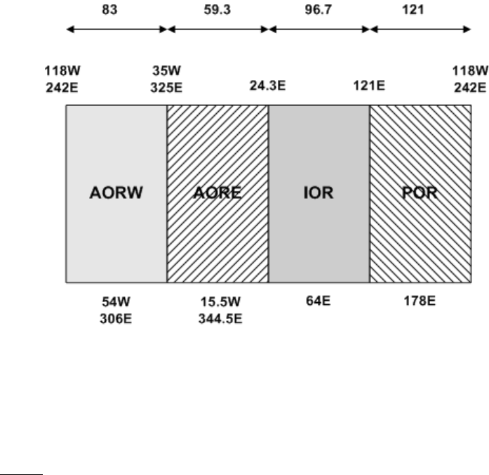
EMS SATCOM
SYSTEM DESCRIPTION, INSTALLATION, AND MAINTENANCE MANUAL
eNfusion™ HSD-440 High-speed Data Terminal
23-15-30 A-1
24 JUN 09
APPENDIX A: INMARSAT SATELLITE BEAM
COVERAGE
Inmarsat operates strategically placed geostationary satellites called I-3 and I-4. I-3 satellites
provide access to services such as Swift64 and Aero H/H+, and I-4 satellites provide access
to SBB services.
Each I-3 satellite is located over and named after an OR. The four satellite ORs are:
• Atlantic Ocean Region-East (AOR-E)
• Atlantic Ocean Region-West (AOR-W)
• Indian Ocean Region (IOR)
• Pacific Ocean Region (POR)
Figure A-1 represents the satellite ORs with approximate transfer coordinates for satellite
transitions.
Figure A-1 Satellite ORs
The four satellite ORs are made up of smaller, spot-beam coverage areas. The following maps
show the Inmarsat satellite spot-beam coverage for the four ORs, and a composite map of
the four regions combined.
NOTE: Figure A-2 and Figure A-3 depict Inmarsat's expectations of coverage but do not
represent a guarantee of service and should not be relied upon. The availability of
service at the edge of coverage areas fluctuates depending upon a variety of
conditions.
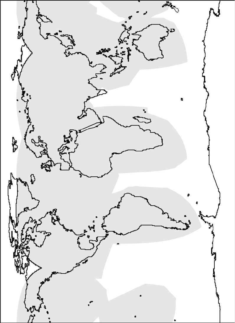
23-15-30 A-2
24 JUN 09
EMS SATCOM
SYSTEM DESCRIPTION, INSTALLATION, AND MAINTENANCE MANUAL
eNfusion™ HSD-440 High-speed Data Terminal
Figure A-2 Inmarsat I3 Satellite Beam Coverage—Composite Map
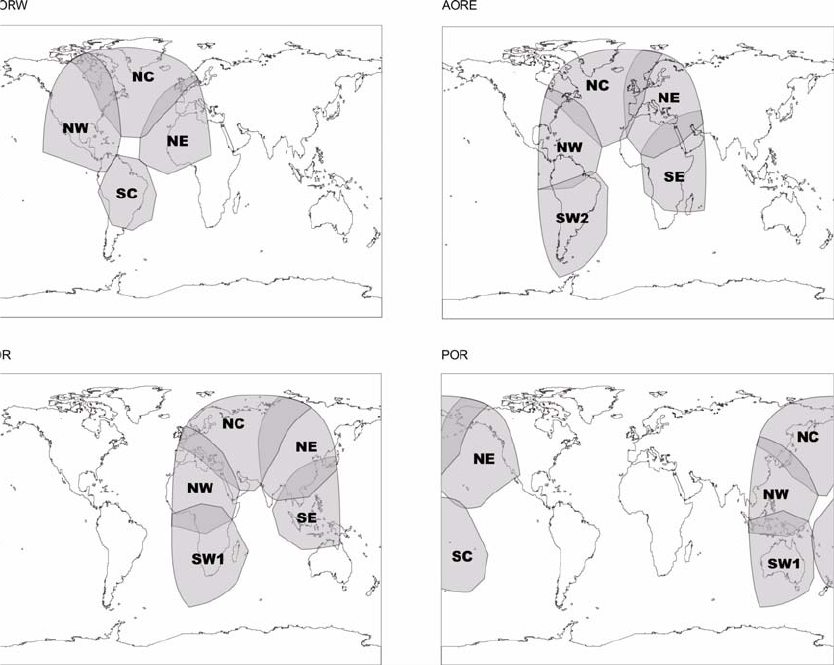
EMS SATCOM
SYSTEM DESCRIPTION, INSTALLATION, AND MAINTENANCE MANUAL
eNfusion™ HSD-440 High-speed Data Terminal
23-15-30 A-3
26 JUN 09
Figure A-3 Inmarsat I-3 Satellite Beam Coverage—OR Maps
At the time of publishing, three I-4 satellites are in service: Americas, EMEA and
Asia-Pacific.
Figure A-4 shows the area that is covered by the I-4 satellites.
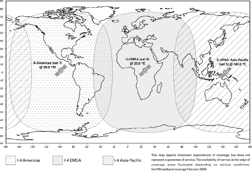
23-15-30 A-4
24 JUN 09
EMS SATCOM
SYSTEM DESCRIPTION, INSTALLATION, AND MAINTENANCE MANUAL
eNfusion™ HSD-440 High-speed Data Terminal
Figure A-4 I-4 Satellite Coverage Map

EMS SATCOM
SYSTEM DESCRIPTION, INSTALLATION, AND MAINTENANCE MANUAL
eNfusion™ HSD-440 High-speed Data Terminal
23-15-30 B-1
24 JUN 09
APPENDIX B: TROUBLESHOOTING CHECKLIST
Before performing the detailed testing and troubleshooting procedures provided in this
manual, read the following Troubleshooting Checklist. Use the Troubleshooting Checklist to
make sure that you have not missed any key steps in the HSD-440 terminal setup.
1. Have you registered with a service provider to activate service?
You must register with an Inmarsat-authorized service provider to activate an account
to access the Satellite Communications network using an HSD-440 terminal. Contact
Inmarsat for a list of available service providers at:
Inmarsat Customer Care
99 City Road, London, EC1Y 1AX
Tel: +44 20 7728 1777
Fax: +44 20 7728 1142
E-mail: customer_care@inmarsat.com
The ISN (supplied by EMS SATCOM) and ICAO address are required to activate an
account.
2. Has your account been activated?
Once registered, your HSD-440 terminal is assigned Inmarsat Serial Numbers which
include FWD IDs. The ICAO address of the HSD-440 terminal must be strapped
accordingly and FWD ID must be entered. Refer to "Installation" on page 3-1 for
detailed strapping and installation instructions.
NOTE: The service registration information may take a few days to be incorporated
into the system databases at the LES level. New terminals being
commissioned are not validated by the LES until their customer database has
been updated by Inmarsat to reflect the registration and activation of your
terminal.
NOTE: To verify that the service registration information has been validated at the
LES, call 33 # for assistance. Confirm with the LES operator that the FWD
IDs assigned to your terminal are valid and active.
3. Is the HSD-440 terminal seated properly?
In cases where the HSD-440 terminal is not fully seated into the ARINC 600 connector
(to the rear of the Fan Tray), the user may experience intermittent system operation.
If intermittent system operation occurs:
• Check that the polarization pins are installed correctly as indicated on the applicable
Outline and Installation diagram.
• Make sure that the HSD-440 terminal is fully inserted into the tray and that the front
hold-down screws are properly tightened to secure the terminal.
4. Is all cabling attached correctly and securely?
Broken connections and improper cabling are the most common causes of HSD-440
terminal malfunctions. Before proceeding with testing and troubleshooting, complete
the following checks:
• Check that all cables and wiring are routed and connected correctly and securely.
23-15-30 B-2
24 JUN 09
EMS SATCOM
SYSTEM DESCRIPTION, INSTALLATION, AND MAINTENANCE MANUAL
eNfusion™ HSD-440 High-speed Data Terminal
• Make sure that the terminal is installed with the correct power source.
• Verify that all external user and networking devices (for example: TAs, routers, fax,
telephones, computers) are connected and configured properly.
5. Have any changes to the system been made?
For previously installed and functional terminals, make note of any changes made to
the system since the last time the terminal functioned without problems.
• Were any new devices or systems connected to the terminal?
• Have any connecting devices or equipment been removed or replaced? If so, check
that all new or replaced connections are attached and configured correctly.
• Have you changed service providers or re-configured the system in any way?
6. Are your LES Access Codes programmed for all ORs?
The system default for LES access codes is set to 0 (zero), which must be configured
to valid LES access codes before operation. Refer to "System Operation" on page
2-1 for details.
7. Was the operational mode of the system strapped or configured correctly?
Verify that the system mode wiring straps match the installation configuration mode.
Only Stand-Alone Mode is currently supported.
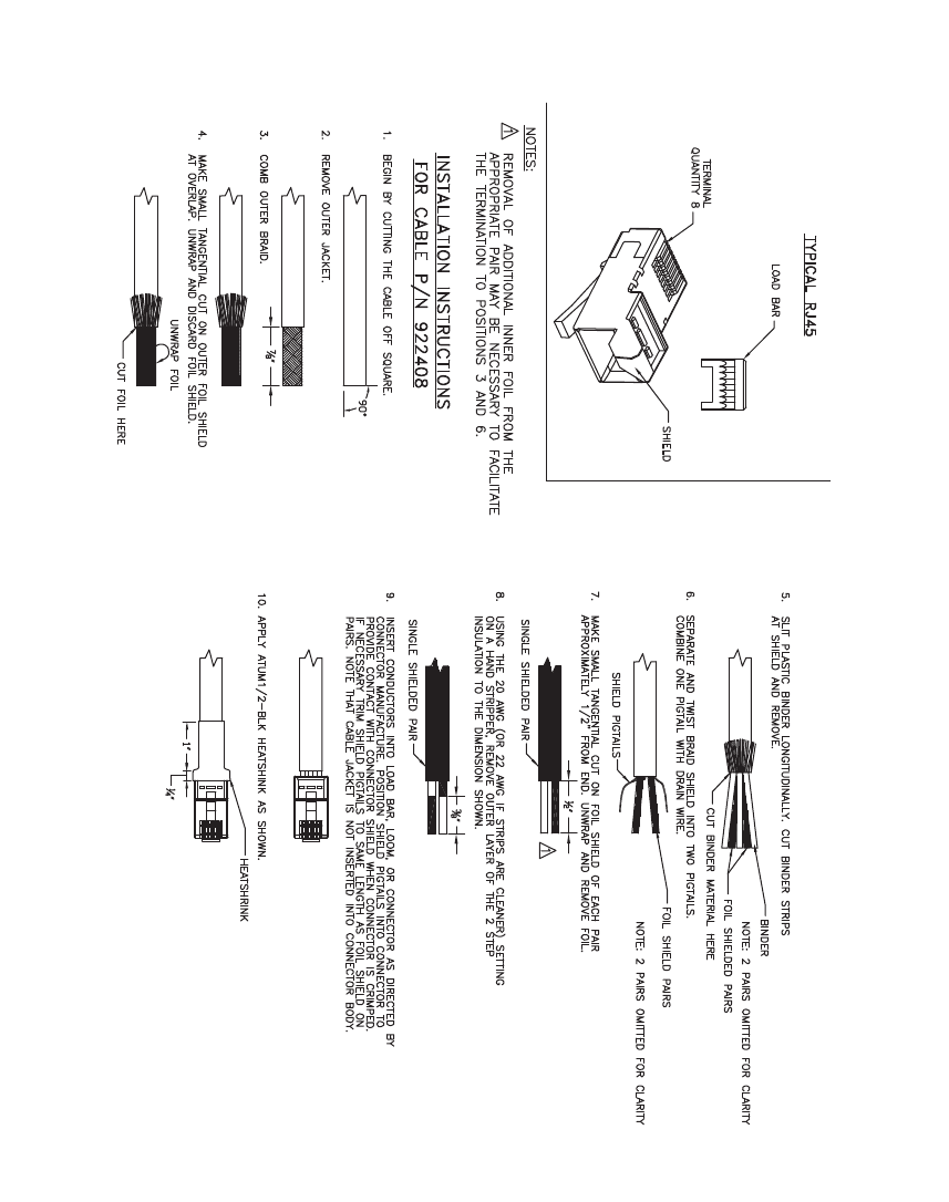
EMS SATCOM
SYSTEM DESCRIPTION, INSTALLATION, AND MAINTENANCE MANUAL
eNfusion™ HSD-440 High-speed Data Terminal
23-15-30 C-1
24 JUN 09
APPENDIX C: RJ45 CABLE TERMINATION DETAILS
Figure C-1 RJ45 Cable Termination Details
23-15-30 C-2
24 JUN 09
EMS SATCOM
SYSTEM DESCRIPTION, INSTALLATION, AND MAINTENANCE MANUAL
eNfusion™ HSD-440 High-speed Data Terminal
Blank Page

EMS SATCOM
SYSTEM DESCRIPTION, INSTALLATION, AND MAINTENANCE MANUAL
eNfusion™ HSD-440 High-speed Data Terminal
23-15-30 D-1
24 JUN 09
APPENDIX D: INSTALLATION PLANNING CHECKLIST
Installation Planning Steps
1. Register the terminal
Record the following information (provided by EMS SATCOM upon purchase)
Terminal Category Type—A
Inmarsat Serial Numbers (ISN) x 2 1
2
Contact your Service Provider and provide the two 12-digit ISNs from above
Record the FWD IDs received (part of the ISN) and corresponding Inmarsat Mobile Numbers
(IMN)
1 2
FWD IDs
(last 6 digits of ISN)
IMNs
ISDN speech
ISDN
(3.1 kHz audio)
ISDN 56 kbps
ISDN 64 kbps
MPDS
Service Provider
LES Access Codes (depend on Service Provider)
AOR-W
AOR-E
IOR
POR
2. Pin Strapping
The following strapping is required
Item Strapped pins
System mode Stand-Alone Mode only
SDI
3. Wiring

23-15-30 D-2
24 JUN 09
EMS SATCOM
SYSTEM DESCRIPTION, INSTALLATION, AND MAINTENANCE MANUAL
eNfusion™ HSD-440 High-speed Data Terminal
Antenna Multi-Control
BITE A/B
HPA Mute A/B
Power
ISDN:
Wire one ISDN line to the ISDN port.
ISDN-1
Ethernet:
Wire both Ethernet ports for SBB
Wire both Ethernet ports to deploy 2 separate networks
Ethernet-1
Ethernet-2
Inertial Navigation System (INS)
Analog Tip/Ring (POTS)
CEPT-E1, Future PBX applications (optional)
4. Configuration
Strap the ICAO address and program the FWD ID
Program the Land Earth Station (LES) Access Codes
Configure the CNX Cabin Gateway if required
Set the GES preferences using the EEPROM settings in Menu 3, option K.
Installation Planning Steps

EMS SATCOM
SYSTEM DESCRIPTION, INSTALLATION, AND MAINTENANCE MANUAL
eNfusion™ HSD-440 High-speed Data Terminal
23-15-30 E-1
24 JUN 09
APPENDIX E: INSTALLATION CHECKLIST
Aircraft Identification: HSD-440 Terminal
Model No.:
HSD-440 Terminal Install.
Mode: HSD-440 Terminal
Serial No.:
Name Signature Date
Checks completed by:
Approved/Witnessed by:
Section Parameter Item N/A 9Value
Installation / Mechanical
Physical Service/maintenance access
Environmental considerations—see
"Environmental Requirements" on page 3-4
Fan Tray Plug configuration—see "Fan Tray
Requirements" on page 3-4
Chassis bonding—see "Chassis Grounding"
on page 3-5
Fan rotation—unobstructed
ARINC 600 Con. Polarized pins
Installation / Electrical
Power
Connections + 28 V dc polarity
115 V ac polarity
Chassis grounding
Voltage Levels + 28 V dc level
115 V ac level
IRS Input IRS wiring
IRS format

23-15-30 E-2
24 JUN 09
EMS SATCOM
SYSTEM DESCRIPTION, INSTALLATION, AND MAINTENANCE MANUAL
eNfusion™ HSD-440 High-speed Data Terminal
Move the aircraft in a circle and check the signal and C/No.
Config. Strap
Pins SDI
System configuration
ICAO address
WOW (optional)
Ethernet Wired to RJ45 distribution points
ISDN Wired to RJ45 distribution points
Remotes Manual reset switch operation
Maintenance port (DB9 access)
Power and Fault indicators
RF Coaxial Rx i/p cable loss
Tx o/p cable loss
Antenna Antenna manufacturer and type
Wired as per manufacturer
Configuration LES Access codes
Stand-Alone Mode
FWD ID
Test
System
Power-Up Visual LED indications
Power-up computer display
Test On-Air
System Logon Reset message observed
Logon verified
Test
Optional Checks Ground segment
Flight segment
Section Parameter Item N/A 9Value

EMS SATCOM
SYSTEM DESCRIPTION, INSTALLATION, AND MAINTENANCE MANUAL
eNfusion™ HSD-440 High-speed Data Terminal
23-15-30 E-3
24 JUN 09
Operational Test
Heading
(Deg) Antenna
Selected Antenna
Azimuth
HSD-440 terminal
CH 1 CH 2 CH 3 CH 4
C/No Signal C/No Signal C/No Signal C/No Signal
15
30
45
60
75
90
105
120
135
150
165
180
195
210
225
240
255
270
285
300
315
330
345
360
23-15-30 E-4
24 JUN 09
EMS SATCOM
SYSTEM DESCRIPTION, INSTALLATION, AND MAINTENANCE MANUAL
eNfusion™ HSD-440 High-speed Data Terminal
Blank Page

EMS SATCOM
SYSTEM DESCRIPTION, INSTALLATION, AND MAINTENANCE MANUAL
eNfusion™ HSD-440 High-speed Data Terminal
23-15-30 F-1
24 JUN 09
APPENDIX F: ACARS/CMU MESSAGES
The ACARS/CMU communicates with the HSD-440 terminal using two types of
communications: Broadcast messages and Bit Oriented Protocol (BOP) messages. Both
types of communication are supported at the same time.
This section includes descriptions of the messages that the ACARS/CMU will transmit
to the HSD-440 terminal and receive from the HSD-440 terminal.
(1) Understanding Broadcast Messages
In this communication type, the ACARS/CMU uses an ARINC 429 bus to convey
status word exchanges, join/leave words, and other control and command
communications to the HSD-440 terminal using conventional ARINC 429 broadcast
techniques.
The ACARS/CMU can transmit messages to the HSD-440 terminal and receive
messages from the HSD-440 terminal using this communication type.
(a) Understanding Messages Transmitted to the HSD-440 Terminal
The ACARS/CMU transmits broadcast mode messages, including identification
and status words, to the HSD-440 terminal.
The rate at which the ACARS/CMU transmits messages to the HSD-440
terminal depends on the device from which the message is coming, as shown
in Table F-1.
Table F-1 ACARS/CMU Update Rates for Different Devices
CMU Input Port Activity Label Minimum
Update Rate
(Hz)
Cabin Terminal 1 172 1
Cabin Terminal 2 172 1
CFDIU 125 1
X-Talk Bus N/A N/A
ACMS 172 1
FMC 1 270 1
FMC 2 270 1
HFDR 1 270 1
HFDR 2 270 1
MCDU 1 172 1
MCDU 2 172 1
MCDU 3 172 1
OOOI 1 Aircraft specific 1
OOOI 2 Aircraft specific 1
Printer 350 1
SDU 1 270 1

EMS SATCOM
SYSTEM DESCRIPTION, INSTALLATION, AND MAINTENANCE MANUAL
eNfusion™ HSD-440 High-speed Data Terminal
23-15-30 F-2
24 JUN 09
For all devices connected to the ACARS/CMU, a bus is active when the
ACARS/CMU receives three consecutive words at the specified rate. A bus has
failed when the ACARS/CMU fails to receive three consecutive words.
1. Understanding System Identification Label 172
Each ACARS/CMU transmits system identification label 172 (SAL 304) to
the HSD-440 terminal. Attachment 6 from ARINC Characteristic 758
describes the word format of this label.
2. Understanding Status Word 1; Label 270
Each ACARS/CMU transmits status word 1 to the HSD-440 terminal. The
standby ACARS/CMU checks to see if its status words are the same as the
active ACARS/CMU using its cross-talk connections. In some cases, the
status words should be different, as shown in Table F-2.
SDU 2 270 1
OOOI 3 Aircraft specific 1
OOOI 4 Aircraft specific 1
OOOI 5 Aircraft specific 1
OOOI 6 Aircraft specific 1
VDR 1 270 1
VDR 2 270 1
VDR 3 270 1
XPDR/ICAO 1 275 1
XPDR/ICAO 2 275 1
FMC HS 1 270 1
FMC HS 2 270 1
EFB-1 172 1
EFB-2 172 1
Table F-2 Status Word 1 Differences
Bit Label Meaning
9270 Determines the position of the ACARS/CMU in the cockpit;
see Table F-3
10 276 Determines the position of the ACARS/CMU in the cockpit;
see Table F-3
16 270 Determines the health of the ACARS/CMU
20 270 Determines which ACARS/CMU is active and which is on
standby
Table F-1 ACARS/CMU Update Rates for Different Devices (Continued)
CMU Input Port Activity Label Minimum
Update Rate
(Hz)

EMS SATCOM
SYSTEM DESCRIPTION, INSTALLATION, AND MAINTENANCE MANUAL
eNfusion™ HSD-440 High-speed Data Terminal
23-15-30 F-3
24 JUN 09
The ACARS/CMU transmits its position in the cockpit to the HSD-440
terminal using bits 9 and 10, as shown in Table F-3.
Attachment 6 from ARINC Characteristic 758 describes the word format of
this label.
3. Understanding Status word 2; Label 276
Each ACARS/CMU transmits status word 2 to the HSD-440 terminal. The
standby ACARS/CMU checks to see if its status words are the same as the
active ACARS/CMU using its cross-talk connections. In some cases, the
status words should be different, as shown in Table F-3.
Attachment 6 from ARINC Characteristic 758 describes the word format of
this label.
4. Understanding ICAO Address Words One and Two; Labels 214 and 216
Each ACARS/CMU transmits the same 24 bit ICAO address to the HSD-440
terminal via address words one and two. Table F-4 shows the labels and
their bit positions.
Each ACARS/CMU identifies itself using bits 9 and 10, as shown in Table F-3.
If straps on the HSD-440 terminal ARINC 600 connector are present, they
will override the ICAO address content of these words. ORT settings will also
override the ICAO address if the override bit is set.
Attachment 6 from ARINC Characteristic 758 describes the word format of
these labels.
22-25 276 HF Status (HFDL Installed and HFDL Failed)
26 Determines whether an ACARS or CMU is installed; ACARS
= 1, CMU = 0
Table F-3 Bits 9 and 10 Positions
SDI 1 (bit 9) SDI 2 (bit 10) Position
0 0 Single
0 1 Left
1 0 Right
1 1 Not used
Table F-4 ICAO Address Words One and Two Labels
Label Bits Bit positions
214 first 16 bits 14–29
216 last 8 bits 13–20
Table F-2 Status Word 1 Differences (Continued)
Bit Label Meaning

EMS SATCOM
SYSTEM DESCRIPTION, INSTALLATION, AND MAINTENANCE MANUAL
eNfusion™ HSD-440 High-speed Data Terminal
23-15-30 F-4
24 JUN 09
5. Understanding FWD ID Address Word One and Two; Labels 220 and 221
Each ACARS/CMU transmits the same 24 bit FWD ID address to the
HSD-440 terminal. Table F-5 shows the labels and their bit positions.
Since each Swift64 channel requires a FWD ID, additional FWD IDs may be
derived from the first FWD ID using an internal lookup table. Each
ACARS/CMU can transmit a second FWD ID using address words identical
to labels 220 and 221, but using labels 222 and 223, respectively. If the ORT
contains a FWD ID, it will override the content of these words.
ARINC 781 Supplement 1 describes the word format of these labels.
6. Understanding Time Clock Time Word; Label 150
Each ACARS/CMU transmits the time word to the HSD-440 terminal on the
A429 bus. The format for the time word is shown in Table F-6.
7. Understanding Time Clock Date Word; Label 260
Each ACARS/CMU transmits the date word to the HSD-440 terminal on the
A429 bus. The format for the date word is shown in Table F-7.
Table F-5 FWD ID Address Word One Labels
Label Bits Bit positions
220 first 16 bits 14–29
221 last 8 bits 13–20
Table F-6 Time Clock Time Word Format
Bit Position(s) Label Description
31–30 SSM SSM per A429P1
28–24 Hours 5 Bit binary for hours; 0–23
23–18 Minutes 6 Bit binary for minutes; 0–59
17–12 Seconds 6 Bit binary for seconds; 0–59
11 Pad to Zero Binary 0
10–9 SDI See Table F-3
8–1 Octal Label 150
Table F-7 Time Clock Date Word Format
Bit Position(s) Label Description
31–30 SSM SSM per A429P1
29–28 Tens of Days 2 Bit BCD for tens of days of calendar month; 0–3
27–24 Days 5 Bit BCD for days; 0–9
23 Tens of Months 1 Bit BCD for tens of months; 0–1
22–19 Months 4 bit BCD for months 0–9

EMS SATCOM
SYSTEM DESCRIPTION, INSTALLATION, AND MAINTENANCE MANUAL
eNfusion™ HSD-440 High-speed Data Terminal
23-15-30 F-5
24 JUN 09
(b) Understanding Messages Received from the HSD-440 Terminal
The HSD-440 terminal transmits the following identification and status words to
all ACARS/CMUs.
Table F-8 shows Attachment 6 from ARINC Characteristic 758, which describes
the rates at which the HSD-440 terminal transmits messages to the
ACARS/CMU.
18–15 Tens of years 4 Bit BCD for tens of years 0–9
14–11 years 3 Bit BCD for years 0–9
10–9 SDI See Table F-3
8–1 Octal Label 260
Table F-8 HSD-440 Terminal Transmission Rates
Label Name Rate General
Output
Buses 1,2
General
Output
Buses
3,4
DFS/
UTC
Comm
Output
Bus 4
Comm
Output
Buses
6,7
General
Output
Buses
5,9,10
030 DFS Tuning word 5/S X
172 Subsystem
Identifier 1/S X X X X X
377 Equipment
Identifier 1/S X
350 BITE Word 1
(Binary) 1/S X
351 BITE Word 2
(Binary) 1/S X
125 UTC BCD 1/S X
150
260
UTC Binary
UTC BCD Date
1/S
1/S
X
X
270 Status Output 1 1/S X X X X X
276 Status Output 2 1/S X X X X X
214 ICAO 24-bit
aircraft address
word 1
1/S X X X X X
216 ICAO 24-bit
aircraft address
word 2
1/S X X X X X
047 DFS Autotune
Word 8.33 kHz 5/S X
Table F-7 Time Clock Date Word Format (Continued)
Bit Position(s) Label Description

EMS SATCOM
SYSTEM DESCRIPTION, INSTALLATION, AND MAINTENANCE MANUAL
eNfusion™ HSD-440 High-speed Data Terminal
23-15-30 F-6
24 JUN 09
1. Understanding System Identification Label 172
The HSD-440 terminal transmits system identification label 172 (SAL 307)
if it is a single HSD-440 terminal that should be identified as SDU 1, as per
ARINC 741 and ARINC 758. If the HSD-440 terminal should be identified as
SDU 2, it transmits label 172 (SAL 173).
You can find the SDU identity information in the ORT. If no information is
available, the terminal identifies itself as SAL 307 by default.
ARINC 781 Supplement 1 describes the word format of these labels.
2. Understanding Status Word 1; Label 270
The HSD-440 terminal transmits status word 1 to the ACARS/CMU. The
general format of status word 1 is defined in ARINC 781 Supplement 1;
however, the representation of each bit is shown in Table F-9.
Table F-9 Status Word 1 Bits
Bit(s) Description If Set
9–10 SDI (per ARINC
Specification 429
Section 2.1.4)
•Set to 00, all call
11 Data Link via CMU
Inactive • Due to equipment failure, no active ARINC 429
input buses from the CMUs (also indicated by bits
12 and/or 19) or no logon
12 CMU 1 Inactive • CMU 1 transmission of a valid Label 270 is inactive
13 Voice Unavailable • Terminal is logged off or logged on to the Low Gain
System for reasons other than equipment failure;
i.e., Low Gain Reversion because of operation in
a key hole, very low elevation angles, or blockage
• Bit may be used to generate a cockpit advisory
message (e.g., >SATCOM VOICE
UNAVAILABLE)
14 SELCAL • Indicates that a new cockpit voice circuit has been
established for a ground-initiated call
• Depending on the aircraft setting, this bit may result
in a visual annunciation of the new call on the
EICAS/ECAM/EDU and activation of the cockpit
chime
• Crew should refer to the EICAS/ECAM/EDU to
determine which system is annunciating the call
• Bit should remain set until an appropriate
acknowledgement is received
• Crew should make sure that the bit has been
cleared in all transmitted samples for at least two
seconds prior to being set, and then set for at least
four seconds or until the annunciation is
acknowledged, whichever occurs last

EMS SATCOM
SYSTEM DESCRIPTION, INSTALLATION, AND MAINTENANCE MANUAL
eNfusion™ HSD-440 High-speed Data Terminal
23-15-30 F-7
24 JUN 09
15 Message Alert with
Chime • Refer to MCDU messages for timely information
• Terminal should clear this bit once positive pilot
response has been detected
16 Message Alert without
Chime • Refer to MCDU messages for routine information
• Terminal should clear this bit once positive pilot
response has been detected
17 Not Logged-On • Terminal is not logged onto a ground station
18 Master/Slave • Originating terminal is the slave or the disabled unit
in a dual installation
19 CMU 2 Inactive • CMU 2 transmission of valid Label 270 is detected
inactive
20 Cockpit Fault • No cockpit voice nor CMU data transmissions via
terminal are possible (due to equipment failure)
21 Cockpit Voice Fault • No cockpit voice transmissions via terminal are
possible due to equipment failure
22 Voice Call 1 • Terminal has detected a low priority (4) flight deck
incoming voice call on channel 1
23 Voice Call 2 • Terminal has detected a low priority (4) flight deck
incoming voice call on channel 2
24 Voice Alert 1 • Terminal has detected a high priority (1, 2, or 3)
flight deck incoming voice call on channel 1
25 Voice Alert 2 • Terminal has detected a high priority (1, 2, or 3)
flight deck incoming voice call on channel 2
26 Cockpit Voice
Communication 1 • A cockpit voice communication is connected on
channel 1
27 Cockpit Voice
Communication 2 • A cockpit voice communication is connected on
channel 2
28 • Reserved
Table F-9 Status Word 1 Bits (Continued)
Bit(s) Description If Set

EMS SATCOM
SYSTEM DESCRIPTION, INSTALLATION, AND MAINTENANCE MANUAL
eNfusion™ HSD-440 High-speed Data Terminal
23-15-30 F-8
24 JUN 09
3. Understanding Join/Leave Word; Label 271
Each of the Aeronautical Telecommunications Network (ATN) subnetworks
transmits join and leave words to the ACARS/CMU whenever a path to a
specified ground address changes.
The join event notifies the ACARS/CMU that a new path to a specified ground
address is available, triggering ATN air-to-ground communications. The
leave event notifies the ACARS/CMU that a path to a specified ground
address has been closed, ending ATN air-to-ground communications.
Table F-10 shows the definitions of the bits in the join/leave word.
29 Data • No active ACARS/CMU is available at the SDU, or
the active ACARS/CMU does not respond with a
Loop Word in response to a Test Word
• This bit being set can be caused by the following:
• Bus inactivity on all ACARS/CMU inputs
• Bus activity, but no declared active
ACARS/CMU
• Bit may be used to set a cockpit advisory message
(e.g., >SATCOM DATA) indicating to the flight crew
a loss of data link capability due to a failure in the
ACARS/CMU interface.
30–31 SSM (per ARINC
Specification 429,
Sections 2.1.5 and
2.1.5.3, except that 11 =
Not Defined)
Table F-10 Join/Leave Word Bits
Bits Defines
Bits 8–1 Word Label 271:
• Uses the A429 convention
• Coded as 10011101
Bits 16–9 GES ID:
• 0 is an invalid ID
• FF is used for all GESs
• ID numbers between 1 and FE are valid GES IDs
• GES ID is known to the HSD-440 terminal
Bits 22–17 Satellite ID
Table F-9 Status Word 1 Bits (Continued)
Bit(s) Description If Set

EMS SATCOM
SYSTEM DESCRIPTION, INSTALLATION, AND MAINTENANCE MANUAL
eNfusion™ HSD-440 High-speed Data Terminal
23-15-30 F-9
24 JUN 09
4. Understanding Fault Summary Word 1; Label 350
The HSD-440 terminal transmits fault summary word 1 to monitor the
function of units that are part of or connected to the HSD-440 terminal. The
bits of this word are shown in Table F-11.
ARINC Characteristic 741 describes the word format of this label.
5. Understanding Fault Summary Word 2; Label 351
The HSD-440 terminal transmits fault summary word 2 to monitor the
function of the ARINC 429 buses of the units that are part of or connected
to the HSD-440 terminal. The bits of this word are shown in Table F-12.
Bits 25–23 Inmarsat Service:
• Aero L 000
• Aero I 001
• Aero H 010
• Aero H+ 011
Bits 28–26 Not used; padded with zeros
Bit 29 Data link from the AES to the GES:
• Available (a Join message; Bit = 1)
• Not Available (a Leave message; Bit = 0)
• Identified by the GES ID and Satellite ID fields
• CMU uses this information to initiate networklayer virtual circuits
with available ground routers by determining the ground routers’
DTE addresses from the provided GES identity
• Bits 9–16, (GES) and Bits 17–22 (Satellite ID) uniquely identify
a GES
• Aero Service Type field may be used by the CMU to make routing
decisions
Bits 31–30 SSM information (ARINC 429 para 2.1.5)
Table F-11 Fault Summary Word 1 Bits
Bits Use
29–11 Report systems as fail or OK
11, 13, 16, 19, and 21 Report a fault
Table F-10 Join/Leave Word Bits (Continued)
Bits Defines

EMS SATCOM
SYSTEM DESCRIPTION, INSTALLATION, AND MAINTENANCE MANUAL
eNfusion™ HSD-440 High-speed Data Terminal
23-15-30 F-10
24 JUN 09
ARINC Characteristic 741 describes the word format of this label.
(2) Understanding BOP Messages
In BOP messages, the ACARS/CMU uses Version 1 of the BOP to convey
non-broadcast-type messages between the aircraft and ground ends of the HSD-440
terminal, as published in ARINC 429 P3.
Timer values are set to the default definitions in ARINC Specification 429, as shown
in Table F-13, Table F-14, and Table F-15.
Table F-12 Fault Summary Word 2 Bits
Bits Use
29–11 Report systems as inactive or OK
13, 14, 15, 16 , 17, 21, and 24 Report that no bus activity is detected by the HSD-440
terminal
Table F-13 BOP Events
Event Description Standard
Value
N1Max number of RTS repeats following NCTS 5
N2Max number of RTS repeats following Busy 20
N3Max number of RTS repeats following No response 5
N4Number of NAK words received before declaring failure
of communication 3
N5Number of SYN words received before declaring failure
of communication 3
N6Max number of ALO repeats following No response 3
Table F-14 Variables of Low-Speed BOP—Version 1
Time Description Min
Value Max
Value
Timer or
Design Goal
for Source or
Sink
Notes Reference
T1CTS/NCTS send time 0 ms 100
ms Goal for Sink 22.5.7
T2RTS repeat time after
receipt of NCTS 500
ms 700
ms Timer for
Source 2.5.7.2
T3Busy send time 0 ms 100
ms Goal for Sink 22.5.7.3
T4RTS repeat time after
receipt of Busy 15 sec 18 sec Timer for
Source 2.5.7.3
T5RTS repeat time if no
response 500
ms 700
ms Timer for
Source 2.5.7.4

EMS SATCOM
SYSTEM DESCRIPTION, INSTALLATION, AND MAINTENANCE MANUAL
eNfusion™ HSD-440 High-speed Data Terminal
23-15-30 F-11
24 JUN 09
T6Time of random timer to
resolve RTS conflicts 50 ms 500
ms Goal for Source 32.5.81
T7Increment of time T610 ms 100
ms Goal for Source 32.5.81
T8ACK/NAK/SYN send time 0 ms 200
ms Goal for Sink 22.5.13
T9LDU timeout following CTS 2.5
sec 2.7
sec Timer for Sink 2.5.13.2
1.5.13.6
T10 ACK/NAK timeout 2.7
sec 3.0
sec Timer for
Source 42.5.16
T11 Loop back send time 0 ms 100
ms Goal for Sink 22.5.17.1
T12 ALO repeat time if no
response to ALO 200
ms 250
ms Timer for
Source 2.5.19.1
T13 SOT send time after receipt
of CTS 0 ms 200
ms Goal for Source 22.5.10
T14 Incomplete file timeout 2 min 2.2
min Timer for Sink 2.5.14.3
T15 ALR send time 0 ms 180
ms Goal for Sink 22.5.19.1.2
T16 ACK/NAK timeout after EOT 220
ms 330
ms Timer for
Source 2.5.16
Table F-15 Variables of High-Speed BOP—Version 1
Time Description Min
Value Max
Value
Timer or
Design Goal
for Source or
Sink
Notes Reference
T1CTS/NCTS send time 0 ms 100
ms Goal for Sink 22.5.7
T2RTS repeat time after receipt
of NCTS 100
ms 140
ms Timer for
Source 2.5.7.2
T3Busy send time 0 ms 100
ms Goal for Sink 22.5.7.3
T4RTS repeat time after receipt
of Busy 1.0
sec 1.2
sec Timer for
Source 2.5.7.3
T5RTS repeat time if no
response 150
ms 200
ms Timer for
Source 2.5.7.4
Table F-14 Variables of Low-Speed BOP—Version 1 (Continued)
Time Description Min
Value Max
Value
Timer or
Design Goal
for Source or
Sink
Notes Reference

EMS SATCOM
SYSTEM DESCRIPTION, INSTALLATION, AND MAINTENANCE MANUAL
eNfusion™ HSD-440 High-speed Data Terminal
23-15-30 F-12
24 JUN 09
(a) Understanding BOP Options
The HSD-440 terminal uses the following BOP options for the ACARS/CMU
interface. The ORT specifies the values for these options. If no information is
available, then the options default to the values shown in Table F-16.
T6Time of random timer to
resolve RTS conflicts 50 ms 500
ms Goal for Source 32.5.81
T7Increment of time T610 ms 100
ms Goal for Source 32.5.81
T8ACK/NAK/SYN send time 0 ms 200
ms Goal for Sink 22.5.13
T9LDU timeout following CTS 400
ms 440
ms Timer for Sink 2.5.13.2
2.5.13.6
T10 ACK/NAK timeout 600
ms 660
ms Timer for
Source 42.5.16
T11 Loop back send time 0 ms 100
ms Goal for Sink 22.5.17.1
T12 ALO repeat time if no
response to ALO 200
ms 250
ms Timer for
Source 2.5.19.1
T13 SOT send time after receipt
of CTS 0 ms 100
ms Goal for Source 22.5.10
T14 Incomplete file timeout 10 sec 11 sec Timer for Sink 2.5.14.3
T15 ALR send time 0 ms 180
ms Goal for Sink 22.5.19.1.2
T16 ACK/NAK timeout after EOT 220
ms 330
ms Timer for
Source 2.5.16
Table F-16 BOP Option Defaults
Option Value Notes
O1 Half Half or Full Duplex Operation
O2 ORT value High or Low Speed Bus
Low speed is default
O3 No Automatic CTS when ready
O4 No Accept Automatic CTS
O5 Yes
(high-speed
data terminal)
System Priority to Resolve RTS Conflict
O6 -- Spare
Table F-15 Variables of High-Speed BOP—Version 1 (Continued)
Time Description Min
Value Max
Value
Timer or
Design Goal
for Source or
Sink
Notes Reference

EMS SATCOM
SYSTEM DESCRIPTION, INSTALLATION, AND MAINTENANCE MANUAL
eNfusion™ HSD-440 High-speed Data Terminal
23-15-30 F-13
24 JUN 09
(b) Understanding LDUs and File Size
BOP messages use Link Data Units (LDUs) encoded in binary octets to transmit
data. LDUs conform to the following rules:
• The data is transmitted from a source and is received by a sink.
• LDUs consist of a set of contiguous ARINC 429 32 bit data words.
• The initial data word of each LDU shall be a Start of Transmission (SOT)
word.
• The end data word of each LDU shall be an End of Transmission (EOT).
• No data file shall exceed 255 LDUs.
(c) Understanding LDU Size and Word Count
LDUs may vary in size from 3 to 255 ARINC 429 words. The minimum LDU
consists of one SOT word, one data word, and one EOT word, and the maximum
LDU consists of one SOT, 253 data words, and one EOT.
The HSD-440 terminal calculates word count when it organizes an LDU for
transmission. The word count appears in the RTS and CTS data words. See
"Understanding Protocol Words" on page F-15.
(d) Understanding Word Format
The general word format of a BOP word is given in ARINC 429 (Attachment 11,
Table 11-A). The bit definitions are shown in Table F-17.
O7 -- Spare
O8 Yes Use of SOLO word
(TEST/LOOP)
O9 -- Spare
O10 Yes Destination code in RTS/CTS /NCTS/BUSY Used
O11 Yes Bit-Protocol verification
O12 No Use subsystem SAL from ALO word
Table F-17 BOP Word Format
Bit Position Description
8-1 SAL
24-9 Data (28-9 for full data words)
28-25 GFI, Control Data or Word Type Extensions
31-29 Word Type
32 Parity Bit
Table F-16 BOP Option Defaults (Continued)
Option Value Notes

EMS SATCOM
SYSTEM DESCRIPTION, INSTALLATION, AND MAINTENANCE MANUAL
eNfusion™ HSD-440 High-speed Data Terminal
23-15-30 F-14
24 JUN 09
1. Understanding SALs
The HSD-440 terminal sends LDUs by point to point by using a label field to
carry the destination SAL; therefore, each LDU that the HSD-440 terminal
sends is prefixed by the SAL for the ACARS/CMU, SAL 304.
The SAL for the HSD-440 terminal is 307 (if designated SDU 1) or 173 (if
designated SDU 2). See ARINC 429, Part 1, attachment 1-1 for a complete
list of all SALs.
2. Understanding Data
Data is sent in 4 or 5 nibble words. See "Understanding Word Types" on
page F-14.
3. Understanding General Format Identifier (GFI) Definitions
Table F-18 defines the GFI definitions.
A GFI of 1110 b indicates a Data 2 Enveloped ACARS Message. This
message indicates to the HSD-440 terminal that this message is to be
passed on through the ACARS network. Only one message is transferred
per link layer ARINC 429 file. If the HSD-440 terminal is unable to deliver an
enveloped message to its destination (ACARS/CMU or GES), the HSD-440
terminal discards the message.
A Data-2 HSD-440 terminal transmits to the GES all messages passed from
the avionics network interface during the time that the HSD-440 terminal is
logged on. If the HSD-440 terminal is not logged on, any messages passed
to the HSD-440 terminal shall be discarded. While the HSD-440 terminal is
logged on, any messages received from the GES shall be forwarded to the
avionics network interface regardless of the state or availability of the
destination avionics equipment.
Any ACARS/CMU message contains a destination code of M if it arrives from
the ground to the ACARS/CMU. Similarly, any message originating from the
ACARS/CMU that is destined for a GES contains a destination code of S.
These codes are embedded in the RTS, CTS, and NCTS protocol words
(See "Understanding Protocol Words" on page F-15.)
(e) Understanding Word Types
The word types in Table F-19 are valid. For a full definition, see ARINC 429 P3,
attachment 11.
Table F-18 GFI Definitions
File Type To GFI
CMU HSD-440 terminal
Label Destination
Code Label Destination
Code
Data2 Enveloped
ACARS Message 304 M307 (1) S1110b (Eh)

EMS SATCOM
SYSTEM DESCRIPTION, INSTALLATION, AND MAINTENANCE MANUAL
eNfusion™ HSD-440 High-speed Data Terminal
23-15-30 F-15
24 JUN 09
1. Understanding the Full Binary Data Word
This word shall transmit 5 nibbles of data. See ARINC 429P3 Attachment 11
for details.
2. Understanding the Partial Binary Data Word
This word shall transmit 4 or less nibbles of data. See ARINC 429P3
Attachment 11 for details.
3. Understanding Protocol Words
The protocol words are shown in Table F-20. The protocol identifier occupies
bits 28-25 of the protocol word.
Table F-19 Word Types
31 30 29 WORD TYPE
0 0 0 Full Binary Data Word
0 0 1 Partial Binary Data Word
0 1 0 Start of Frame—Version 3
0 1 1 End of Frame—Version 3
1 0 0 Protocol Word
1 0 1 Solo Word
1 1 0 Start Of Transmission—Version 1
1 1 1 End Of Transmission—Version 1
Table F-20 Protocol Words and Uses
Protocol word Uses
RTS
(Request to Send)
The HSD-440 terminal issues an RTS to the ACARS/CMU when
it is ready to send an LDU. The RTS contains a destination code
(bits 24–17) and a word count (bits 16–9).
CTS
(Clear to Send)
When the HSD-440 terminal receives an RTS, it issues a CTS to
the ACARS/CMU when the ACARS/CMU is ready to send an LDU.
The CTS contains the same destination code and word count as
the HSD-440 terminal received in the RTS.
Bit 11 of the Status Word Label 270 from the HSD-440 terminal
indicates when a satellite link is available to proceed if this is a
ground destination message.
NCTS
(Not Clear to Send)
When the HSD-440 terminal either receives a valid RTS and is
not ready to accept data or receives an RTS with an invalid
destination or word count, it responds with an NCTS. The NCTS
contains a destination code (bits 24–17).
NAK
(negative
acknowledgement)
If the HSD-440 terminal notes a missing SOT or EOT word, parity
error, word count error, CRC error, or time out error, it will respond
with a NAK. The NAK contains the same file sequence number in
bits 24–17 as the SOT word.

EMS SATCOM
SYSTEM DESCRIPTION, INSTALLATION, AND MAINTENANCE MANUAL
eNfusion™ HSD-440 High-speed Data Terminal
23-15-30 F-16
24 JUN 09
4. Understanding the Solo Word
If the data the HSD-440 terminal is sending consists of only 1 or 2 octets,
then the data can be sent blind using the solo word instead of obtaining a
CTS. Solo words conform to the following rules:
• The solo word contains a 16 bit data field in bits 24–9
• Bits 31–29 are permanently set to 101b
• Solo words are not acknowledged at the link level
• Solo words are not interleaved with data file words during a data file
transfer, however if the HSD-440 terminal receives a solo word during
data transfer, the HSD-440 terminal shall process the solo word normally
and resume file transmission or reception.
ACK
(acknowledgement) If the HSD-440 terminal transfers each word within the designated
time and with odd parity, correct word count, and verified CRC.
The LDU is either next, first, or a duplicate. Then the HSD-440
terminal sends an ACK. The ACK word contains the file sequence
number (bits 24–17) and the LDU sequence number (bits 16–9).
ALO
(aloha)
The HSD-440 terminal can initiate BOP V1 communication by
sending an ALO word out on the bus.
The first ALO word that the HSD-440 terminal transmits contains
the highest version number it supports (bits 12–9). This word
determines the correct protocol to use for the exchange. The ALO
also sends its own SAL (bits 24–17).
ALR
(aloha response)
When the HSD-440 terminal receives an ALO word, it leaves its
present task and responds with an ALR word. The response
contains the protocol version level supported.
SYN The HSD-440 terminal transmits a SYN word to inform the
ACARS/CMU that the construction of the last file that was
transmitted is confused. The reception of a SYN word causes the
ACARS/CMU to abort any reception or transmission in progress.
In addition, if the ACARS/CMU was transmitting, it should
re-initiate transmission of the file that was aborted.
Destination code RTS, CTS, and NTCS words use a destination code. The
destination code field (when used, bits 24–17) indicates the final
destination of the LDU. If the LDU will be used in the HSD-440
terminal, the destination code can be set to 00h. If the LDU is
intended to be passed on to another onboard system, the
destination code indicates that system.
Word count RTS and CTS words use a word count. The word count field (bits
16–9) reflects the number of ARINC 429 words that will be
transmitted in a subsequent LDU. The maximum word count value
is 255 ARINC 429 words.
Table F-20 Protocol Words and Uses (Continued)
Protocol word Uses

EMS SATCOM
SYSTEM DESCRIPTION, INSTALLATION, AND MAINTENANCE MANUAL
eNfusion™ HSD-440 High-speed Data Terminal
23-15-30 F-17
24 JUN 09
The solo word also performs test and loop back functions to test the integrity
of the ARINC 429 bus interconnection between the HSD-440 terminal and
the ACARS/CMU.
The HSD-440 terminal can send a 16 bit loop test pattern word (TEST) on
the ARINC 429 TX bus. The ACARS/CMU then responds with the identical
loop test pattern word (LOOP) on the ARINC 429 RX bus. If the LOOP does
not match the TEST, the HSD-440 terminal indicates a TEST failure.
If the HSD-440 terminal receives a TEST on its ARINC 429 RX bus, it
responds by transmitting an identical LOOP on the ARINC 429 TX bus.
A 4 bit identifier (bits 28–25) identifies the nature of the data being sent by
the solo word. The three types of data are shown in Table F-21.
5. Understanding Start of Transmission (SOT)
When the HSD-440 terminal receives a valid CTS with the destination code
and word count of the previous RTS, then it responds by sending an SOT
word immediately before the LDU. The SOT contains the file sequence
number, the GFI, and the LDU sequence number.
The file sequence number (bits 24–17) of the SOT word is an 8 bit number
assigned to the data file. It is initialized to 00h and increments by 1h for each
new file sent over the link. After reaching FFh, the file sequence number
returns to 01h and recommences incrementing by 1h for each new file sent.
A file consisting of multiple LDUs has the same file sequence number in each
SOT word of each LDU. The file sequence number is also used in ACK and
NAK words.
The LDU sequence number (bits 16–9) of the SOT word is an 8 Bit number
assigned to the LDU. It is initialized to 00h and increments by 1h for each
LDU sent (of the same file). The LDU sequence number resets to 00h at the
beginning of each new file. The LDU sequence number is also used in the
ACK word.
6. Understanding End of Transmission (EOT)
Each LDU is terminated by an EOT word. Bit 25 indicates if this LDU is the
final LDU of the transfer. If it is, then this bit shall be set to 1; if it is not the
final LDU, it shall be set to 0. The EOT also contains the CRC word in bits
24–9. See ARINC 429 P3, paragraph 2.5.12, for details on generating and
decoding the CRC word.
Table F-21 Data Types
Purpose Bits 28-25b Description
Test 0000b 16 Bit Test Pattern
Loop 0001b 16 Bit Loop Back
Solo Word ID 16 Bit Data filed
EMS SATCOM
SYSTEM DESCRIPTION, INSTALLATION, AND MAINTENANCE MANUAL
eNfusion™ HSD-440 High-speed Data Terminal
23-15-30 F-18
24 JUN 09
Blank Page

EMS SATCOM
SYSTEM DESCRIPTION, INSTALLATION, AND MAINTENANCE MANUAL
eNfusion™ HSD-440 High-speed Data Terminal
23-15-30 G-1
24 JUN 09
APPENDIX G: INTERNATIONAL ACCESS AND
COUNTRY CODES
Table G-1 shows a list of countries with their associated country codes and international
access codes.
Table G-1 International Access and Country Codes
Country Country Code International Access Code
Afghanistan 93 00
Albania 355 00
Algeria 213 00
Angola 244 00
Anguilla +1 (264) 011
Antigua +1 (268) 011
Argentina 54 00
Armenia 374 00
Aruba 297 00
Australia 61 00 11
Austria 43 00
Bahamas +1 (242) 011
Bahrain 973 00
Bangladesh 880 00
Barbados +1 (246) 011
Belarus 375 810
Belgium 32 00
Belize 501 00
Benin 229 00
Bermuda +1 (441) 011
Bolivia 591 00 10
Bosnia and Hercegovina 387 99
Botswana 267 00
Brazil 55 00
British Virgin Islands +1 (284) 011
Bulgaria 359 00
Burkina Faso 226 00
Burma (Myanmar) 95 00
Burundi 257 90
Cambodia 855 001

EMS SATCOM
SYSTEM DESCRIPTION, INSTALLATION, AND MAINTENANCE MANUAL
eNfusion™ HSD-440 High-speed Data Terminal
23-15-30 G-2
24 JUN 09
Cameroon 237 00
Canada 1011
Cape Verde 238 0
Cayman Islands +1 (345) 011
Central African Republic 236 19
Chad 235 15
Chile 56 00
China 86 00
Colombia 57 009
Comoros 269 00
Congo (Brazzaville) 242 00
Congo (Kinshasa, formerly Zaire) 243 00
Cook Islands 682 00
Costa Rica 506 00
Cote d'Ivoire (Ivory Coast) 225 00
Croatia 385 99
Cuba 53 119
Cyprus 357 00
Czech Republic 420 00
Denmark 45 00
Diego-Garcia 246 00
Djibouti 253 00
Dominica +1 (767) 011
Dominican Republic +1 (809), +1 (829) 011
East Timor 670 00
Ecuador 593 00
Egypt 20 00
El Salvador 503 0
Equatorial Guinea 240 00
Eritrea 291 00
Estonia 372 810
Ethiopia 251 00
Falkland Islands 500 01
Faroe Islands 298 009
Fiji 679 5
Finland 358 00
France 33 00
Table G-1 International Access and Country Codes (Continued)
Country Country Code International Access Code

EMS SATCOM
SYSTEM DESCRIPTION, INSTALLATION, AND MAINTENANCE MANUAL
eNfusion™ HSD-440 High-speed Data Terminal
23-15-30 G-3
24 JUN 09
French Antilles 590 00
French Guiana 594 00
French Polynesia 689 00
Gabon 241 00
Gambia 220 00
Germany 49 00
Ghana 233 00
Gibraltar 350 00
Greece 30 00
Greenland 299 009
Grenada +1 (473) 011
Guam +1 (671) 011
Guatemala 502 00
Guinea 224 00
Guinea-Bissau 245 00
Guyana 592 001
Haiti 509 00
Honduras 504 00
Hong Kong 852 001
Hungary 36 00
Iceland 354 90
India 91 900
Indonesia 62 001, 008
Iran 98 00
Iraq 964 00
Ireland 353 00
Israel 972 00
Italy 39 00
Ivory Coast (Cote d'Ivoire) 225 00
Jamaica +1 (876) 011
Japan 81 010
Jordan 962 00
Kazakstan 7810
Kenya 254 000
Kuwait 965 00
Kyrgyz Republic 996 00
Laos 856 00
Table G-1 International Access and Country Codes (Continued)
Country Country Code International Access Code

EMS SATCOM
SYSTEM DESCRIPTION, INSTALLATION, AND MAINTENANCE MANUAL
eNfusion™ HSD-440 High-speed Data Terminal
23-15-30 G-4
24 JUN 09
Latvia 371 810
Lebanon 961 00
Lesotho 266 00
Liberia 231 00
Libya 218 00
Liechtenstein 423 00
Lithuania 370 00
Luxembourg 352 00
Macao 853 00
Macedonia 389 00
Madagascar 261 16
Malawi 265 101
Malaysia 60 00
Maldives 960 00
Mali 223 00
Malta 356 356
Marshall Islands 692 011
Martinique 596 00
Mauritania 222 00
Mauritius 230 00
Mayotte and Reunion 262 10
Mexico 52 98
Micronesia 691 011
Moldova 373 00
Monaco 377 00
Mongolia 976 001
Montenegro 382 00
Montserrat +1 (664) 011
Morocco 212 00
Mozambique 258 00
Namibia 264 00
Nauru 674 00
Nepal 977 00
Netherlands 31 00
New Caledonia 687 00
New Zealand 64 00
Nicaragua 505 00
Table G-1 International Access and Country Codes (Continued)
Country Country Code International Access Code

EMS SATCOM
SYSTEM DESCRIPTION, INSTALLATION, AND MAINTENANCE MANUAL
eNfusion™ HSD-440 High-speed Data Terminal
23-15-30 G-5
24 JUN 09
Niger 227 00
Nigeria 234 009
Niue Island 683 00
North Korea 850 00
Northern Mariana Islands
(Commonwealth of) +1 (670) 011
Norway 47 095
Oman 968 00
Pakistan 92 00
Palau 680 011
Palestine 970 00
Panama 507 00
Papua New Guinea 675 05
Paraguay 595 002
Peru 51 00
Philippines 63 00
Poland 48 00
Portugal 351 00
Puerto Rico +1 (787) 011
Qatar 974 00
Romania 40 71
Russia 7810
Rwanda 250 00
Samoa 685 0
San Marino 378 00
Saudi Arabia 966 00
Senegal 221 00
Serbia 381 99
Seychelles 248 00
Sierra Leone 232 00
Singapore 65 001
Slovakia 421 00
Slovenia 386 99
Solomon Islands 677 00
Somalia 252 00
South Africa 27 00
South Korea 82 00
Table G-1 International Access and Country Codes (Continued)
Country Country Code International Access Code

EMS SATCOM
SYSTEM DESCRIPTION, INSTALLATION, AND MAINTENANCE MANUAL
eNfusion™ HSD-440 High-speed Data Terminal
23-15-30 G-6
24 JUN 09
Spain 34 00
Sri Lanka 94 00
St Helena and Tristan da Cunha 290 00
St Kitts +1 (869) 011
St Lucia +1 (758) 011
St Pierre and Miquelon 508 00
St Vincent +1 (784) 011
Sudan 249 00
Suriname 597 002
Swaziland 268 00
Sweden 46 00
Switzerland 41 00
Syria 963 00
Taiwan 886 002
Tajikistan 992 810
Tanzania 255 000
Thailand 66 001
Togolese Republic 228 00
Tokelau 690 00
Tonga 676 09
Trinidad and Tobago +1 (868) 011
Tunisia 216 00
Turkey 90 99
Turkmenistan 993 810
Turks and Caicos +1 (649) 011
Tuvalu, Ellice Islands 688 00
U.S. Pacific Islands +1 670, +1 671,
+1 684 011
U.S. Virgin Islands +1 (340) 011
Uganda 256 000
Ukraine 380 810
United Arab Emirates 971 00
United Kingdom 44 00
United States 1011
Uruguay 598 00
Uzbekistan 998 810
Vanuatu 678 00
Table G-1 International Access and Country Codes (Continued)
Country Country Code International Access Code

EMS SATCOM
SYSTEM DESCRIPTION, INSTALLATION, AND MAINTENANCE MANUAL
eNfusion™ HSD-440 High-speed Data Terminal
23-15-30 G-7
24 JUN 09
Vatican City +39, +379 00
Venezuela 58 00
Vietnam 84 00
Wallis and Futuna 681 19
Yemen 967 00
Yugoslavia (+38 discontinued) 99
Zambia 260 00
Zimbabwe 263 110
Table G-1 International Access and Country Codes (Continued)
Country Country Code International Access Code
EMS SATCOM
SYSTEM DESCRIPTION, INSTALLATION, AND MAINTENANCE MANUAL
eNfusion™ HSD-440 High-speed Data Terminal
23-15-30 G-8
24 JUN 09
Blank Page

EMS SATCOM
SYSTEM DESCRIPTION, INSTALLATION, AND MAINTENANCE MANUAL
eNfusion™ HSD-440 High-speed Data Terminal
23-15-30 H-1
24 JUN 09
APPENDIX H: INMARSAT CAUSE CODES
Table H-1 defines the maintenance port menu fault codes of the HSD-440 terminal.
Table H-1 Inmarsat Cause Code Definitions
Inmarsat Cause Code Code Definition
1001 Call cleared by MES terminal (normal termination of call)
1011 Call failed, MES terminal busy
1012 Call cleared, MES terminal busy
1021 Call failed, MES time-out (no answer)
1081 Call failed, MES terminal not installed
1091 Call failed, MES terminal out-of-service
1092 Call cleared, MES terminal out-of-service
1141 MES preempted clear by higher priority call
1142 MES preempted fixed call by higher priority call
1143 Offered call cleared, pre-empted at MES
1144 Call cleared, MES initiated preemption
1145 Attempted call cleared, pre-empted at MES
1146 Attempted call abandoned by MES terminal
1202 Handover, MES ready
1281 Call failed, MES cannot accept
1291 Call failed, MES cannot accept at present
1351 Call cleared, insufficient free memory
1361 Call cleared by MES cable unwrap
1362 Call cleared, long interruption in reception at MES
1363 MES secondary clear due to repoint OR
1391 Call cleared, traveled distance exceeds 700km
1392 Call cleared, spot beam transition (call terminated because
aircraft left spot beam)
1393 Call cleared, cooperative mode
1451 Call failed, terrestrial circuits congested
1452 Call failed, LES congested (no channel and no circuit)
1502 Handover, LES Ready, normal clear
1551 Call failed, LES congested (no channel)
1581 Call failed, service not provided at this LES
1591 Call failed, service temporarily not available at this LES
1592 Call cleared, credit card type not supported
1651 Call failed, LES congested (no channel terminal)
1661 Call failed, long interruption in reception at LES

23-15-30 H-2
24 JUN 09
EMS SATCOM
SYSTEM DESCRIPTION, INSTALLATION, AND MAINTENANCE MANUAL
eNfusion™ HSD-440 High-speed Data Terminal
1662 LES long term blockage of SCPC MES
1790 Call cleared, failure credit card validation process
1791 Call cleared, failure authentication process
1811 NCS MES ID busy
1812 NCS MES ID busy IPDS
1841 Call cleared, NCS initiated preemption for incoming Pri.1 call
1842 Call cleared, NCS initiated preemption for incoming Pri.2 call
1843 Call cleared, NCS initiated preemption for incoming Pri.3 call
1844 Call cleared, NCS initiated preemption
1851 Call failed, satellite congestion NCS reject no SCPC available
1852 Call failed, satellite congestion NCS reject SCPC does not
match request
1853 Call failed, lease channel congestion
1854 Call failed, MES outside spot beam coverage area
1855 Call rejected, preemption failed, no channel available
1856 Call rejected, spot beam selection failed
1857 Handover failed, channel not available
2000 MES int reject MES RQ invalid CNO
2001 MES int reject MES RQ failed qualification
2010 MES int reject MES RP invalid CNO
2011 MES int reject MES RP failed qualification
2012 MES int reject MES RP operation timeout
2020 MES int reject NCSA missing
2021 MES int reject NCSA invalid CNO
2022 MES int reject NCSA failed qualification
2023 Call failed, Signal lost on NCSA during call setup, check
antenna and try again
2024 Call failed, Missing channel assignment, try again
2025 Call failed, Signal lost on NCSC during call setup, check
antenna and try again
2030 MES int reject LES ID failed qualification
2040 MES int reject SCCS invalid CNO
2041 MES int reject SCCS not paired
2048 Call failed, invalid number dialed
2049 Call failed, terminal not ready for call, try later
2050 Call failed, Not allowed to make another mobile call yet, wait
20 seconds and try again
2051 Call failed, dialed number is barred
Table H-1 Inmarsat Cause Code Definitions (Continued)
Inmarsat Cause Code Code Definition

EMS SATCOM
SYSTEM DESCRIPTION, INSTALLATION, AND MAINTENANCE MANUAL
eNfusion™ HSD-440 High-speed Data Terminal
23-15-30 H-3
24 JUN 09
2052 Call failed, LES selected is barred
2053 Call failed, number dialed must be in a phonebook
2053 Call failed, terminal can only be used with a valid SIM
2055 Call failed, user not logged in
2056 Call failed, user not logged in to SIM
2057 Call failed, LES is not in SIM allowed list
2058 Call cleared, SIM removed during call
2059 Call failed, terminal is locked for outgoing calls
2060 MES int reject NCSS failed qualification
2061 MES int reject spot beam invalid
2062 Call failed, no spot beams in the ocean region, select another
OR
2063 Terminal ID is not set correctly, check with dealer
2070 Lost NCSC signal, seeking
2071 Stand-Alone Mode finished, seeking network
2080 SIM error, check SIM is inserted correctly
2090 MES int reject ORR query invalid
2091 MES int reject ORR invalid
2092 MES int reject MES RR failed qualification
2093 MES int reject MES RR invalid CNO
2094 MES int reject NCRA missing
2095 MES int reject NCRA lost lock
2100 MES int reject illegal call type
2101 MES Int reject illegal peripheral
2102 Call request failed, call already in progress
2103 Call failed, star code is badly formatted
2104 Call failed, cannot accept two address book star codes
2105 Call failed, address book entry not found
2106 Call failed, star code does not exist
2120 MES int reject no transmit power available
2200 Battery flat for terminal operation
2201 Call cleared, used all allocated time for call type
2300 MES int reject no coop response
2301 MES int reject no power
2302 MES int reject no location report
2400 MES int reject no ORA SU found
8000 ACSE Recycling
Table H-1 Inmarsat Cause Code Definitions (Continued)
Inmarsat Cause Code Code Definition

23-15-30 H-4
24 JUN 09
EMS SATCOM
SYSTEM DESCRIPTION, INSTALLATION, AND MAINTENANCE MANUAL
eNfusion™ HSD-440 High-speed Data Terminal
8001 ACSE Top Of Find BB
8002 ACSE Top Of Process BB
8010 ACSE Finding Primary NCS Long
8011 ACSE Finding Secondary NCS Short
8012 ACSE Finding Primary Standalone Short
8013 ACSE Finding Primary NCS Short
8014 ACSE Finding Primary Standalone Long
8018 ACSE Finding Secondary Standalone Short
8019 ACSE Finding Secondary Standalone Long
8020 ACSE Found Primary NCS
8021 ACSE Found Secondary NCS
8022 ACSE Found Primary Standalone
8023 ACSE Found Secondary Standalone
8024 ACSE found primary NGNCS
8025 ACSE found secondary NGNCS
8030 ACSE NSR Invalid
8040 ACSE Inert
8041 ACSE ODU Status
8080 ACSE NSR Valid
8081 ACSE NSR Valid LES A
8100 ACSE Booting
8110 ACSE Booted
8120 ACSE FIDR ID Invalid
8200 ACSE Spot Beam Selection
8201 ACSE Next Spot Beam
8202 ACSE Successful Spot Beam Selection
8203 ACSE Failed To Find Spot Beam
8204 ACSE Spot Beam Selective Clear
8210 ACSE Spot Beam Reject Mobile Call No ID
8211 ACSE Spot Beam Reject Mobile Call No TDM
8300 ACSE ORR
8301 ACSE Successful ORR
8302 ACSE Failed ORR
8303 ACSE No ORR
8304 ACSE ORR Tune NCRA
8305 ACSE ORR MES RR
8306 ACSE failed retry ORR
Table H-1 Inmarsat Cause Code Definitions (Continued)
Inmarsat Cause Code Code Definition

EMS SATCOM
SYSTEM DESCRIPTION, INSTALLATION, AND MAINTENANCE MANUAL
eNfusion™ HSD-440 High-speed Data Terminal
23-15-30 H-5
24 JUN 09
8310 ACSE ORR Query Begin
8311 ACSE ORR Query Burst
8312 ACSE ORR Query Successful
8313 ACSE ORR Query Failed
8400 ACSE Fixed Begin
8401 ACSE Fixed MESRP
8402 ACSE Fixed Call Type Set
8410 ACSE Fixed Tune NCSA
8411 ACSE Fixed Channel Assignment
8420 ACSE Fixed Clearing Call
8421 ACSE Fixed Selective Clear
8480 ACSE Fixed SCPC Begin
8481 ACSE Fixed SCPC Transmitting
8482 ACSE Fixed Authentication Begin
8483 ACSE Fixed Authentication End
8484 ACSE Fixed Power Control
8485 ACSE Fixed MES Connect
8486 ACSE Fixed Ringing Begin
8500 ACSE Mobile Begin
8501 ACSE Mobile MES RQ1
8502 ACSE Mobile MES RQ2
8503 ACSE Mobile Call Type Set
8510 ACSE Mobile Tune NCSA
8511 ACSE Mobile Channel Assignment
8520 ACSE Mobile Clearing Call
8521 ACSE Mobile Selective Clear
8580 ACSE Mobile SCPC Begin
8581 ACSE Mobile SCPC Transmitting
8582 ACSE Mobile Authentication Begin
8583 ACSE Mobile Authentication End
8584 ACSE Mobile Power Control
8585 ACSE Mobile LES Connect
8586 ACSE Mobile Ringing Begin
8600 MPDS SCPC Mode Selected
8800 ACSE cable call begin
8801 ACSE cable call successful
8900 ACSE Logoff Begin
Table H-1 Inmarsat Cause Code Definitions (Continued)
Inmarsat Cause Code Code Definition

23-15-30 H-6
24 JUN 09
EMS SATCOM
SYSTEM DESCRIPTION, INSTALLATION, AND MAINTENANCE MANUAL
eNfusion™ HSD-440 High-speed Data Terminal
8901 ACSE Successful Logoff
8902 ACSE No ORR Logoff
9000 ACSE accepts call
9003 ACSE accepted
9004 ACSE rejected
9020 ACSE call waiting
9021 ACSE idle selective clear
9022 ACSE TDM not found
9080 ACSE rejected fixed call due to invalid NSR
9081 ACSE In MRSi
9082 ACSE sounder turned on
9083 ACSE sounder turned off
9084 ACSE in lock
9085 ACSE out of lock
9086 ACSE ext sounder turned on
9087 ACSE ext sounder turned off
9088 ACSE timer about to expire
9090 ACSE Smartcard activated
9091 ACSE Smartcard removed
9092 ACSE Smartcard error
9100 Peripheral on hook
9101 Peripheral off hook
9102 Peripheral connected
9103 Peripheral ringing
9104 Peripheral ready
9105 Peripheral hanging up
9106 Peripheral hang up
9107 Peripheral not responding
9108 Peripheral dialing
9109 Peripheral abort dialing
9120 Peripheral DTMF accepted
9121 Peripheral DTMF rejected
9122 Peripheral invalid request
9123 Peripheral valid request
9124 Peripheral bonding auto
9125 Peripheral bonding slave
9126 Peripheral bonding none
Table H-1 Inmarsat Cause Code Definitions (Continued)
Inmarsat Cause Code Code Definition

EMS SATCOM
SYSTEM DESCRIPTION, INSTALLATION, AND MAINTENANCE MANUAL
eNfusion™ HSD-440 High-speed Data Terminal
23-15-30 H-7
24 JUN 09
9130 Peripheral STU enabled
9131 Peripheral STU disabled
9200 MSG T_AM received
9201 MSG A_AM received
9202 MSG T_HA received
9203 MMI normal
9204 MMI inert
9205 MMI programming
9206 MMI reboot
9207 MMI powerdown
9208 MMI accepted
9209 MMI rejected
400000 CT SP bad
400000 No call pending
400001 CT SP good
400002 CT SP full
400003 CT SP access denied
400080 CT SP find
400081 CT SP enumerate
400082 CT SP no entries
400090 CT SP delete
400100 CT SP spot beam selection
400105 CT SP MPDS
400110 CT SP ocean region registration
400111 CT SP ORR query
400112 CT SP log off
400120 CT SP cable call
400200 CT SP go idle
400201 CT SP go idle due to configuration
400202 CT SP selective clear
400208 CT SP go idle clear spot beam
400209 CT SP go idle clear NSR
400210 CT SP go inert
400211 CT SP go inert Smartcard
400212 CT SP go inert DDS poll
400900 CT SP ODU status
400901 CT SP ODU status no alarms
Table H-1 Inmarsat Cause Code Definitions (Continued)
Inmarsat Cause Code Code Definition

23-15-30 H-8
24 JUN 09
EMS SATCOM
SYSTEM DESCRIPTION, INSTALLATION, AND MAINTENANCE MANUAL
eNfusion™ HSD-440 High-speed Data Terminal
400902 CT SP ODU status DDS
400910 CT SP prod test
400911 CT SP prod test ODU
401000 CT SP clear spot beam
800124 Mobile aero 64k speech
800404 Mobile data
800504 Mobile facsimile
800606 Mobile 64k UDI
800607 Mobile 56k UDI
800610 Mobile 64k audio 3k1
800622 Mobile aero 64k UDI
800623 Mobile aero 56k UDI
800625 Mobile aero 64k audio 3k1
11A0 Call cleared, credit card not accepted
11D1 Call failed, Request data invalid
11D2 Call failed, insufficient digits in service address
11D3 Call failed, invalid service address
11D4 Call cleared, credit card data information invalid
11D5 Call cleared, invalid country code
11D6 Call cleared, PID information is not consistent
11D7 Call rejected, invalid service for Pri.1 or 2 call
11D8 Call cleared, dialed number not 2 or 3 digits for Pr.1 or 2 call
11E0 Call cleared, invalid credit card PIN at this LES
11E1 Call cleared, too many invalid credit card call attempts
12B1 Call cleared by MES for unspecified reason, for example:
• GPS conflict
• Insufficient HPA power available to make call
• HPA over current
12C2 Call cleared, no credit card valid message received
12C3 Call failed, MES time-out (no terrestrial answer)
12C4 Call cleared, authentication query not received (usually caused
by call setup failure)
12C5 Call cleared, MES missing sup service SU
12C6 Call cleared, MES missing sup service 2SU
12C7 Call cleared, MES missing SCPC channel release SU sup
service
12C8 Handover failed, LES not detected
Table H-1 Inmarsat Cause Code Definitions (Continued)
Inmarsat Cause Code Code Definition

EMS SATCOM
SYSTEM DESCRIPTION, INSTALLATION, AND MAINTENANCE MANUAL
eNfusion™ HSD-440 High-speed Data Terminal
23-15-30 H-9
24 JUN 09
12D1 Call failed, Spot-beam data invalid
12D2 Call failed, invalid scrambling vector
15A1 Call failed, MES not authorized at this LES
15A2 Call failed, service not authorized at this LES
15A3 Call cleared, credit card not authorized
15A4 Call cleared, authentication reply invalid
15A5 Call failed, PID not authorized for any service
15A6 Call failed, PID not authorized for requested service
15B1 Call cleared by LES for unspecified reason
15C1 Call failed, LES time-out (no assignment)
15C2 Call failed, LES time-out (no service address)
15C3 Call failed, LES time-out (no scrambling vector)
15C4 Call failed, no service address and no scrambling vector
15C5 Call cleared, incomplete credit card data information
15C7 Call failed, LES time-out (no MES Connect)
15C9 Call cleared, no authentication reply
15CA Call cleared, notification ack not received
15CB Call cleared, invalid sequence number in notification ack
15CC Handover failed, no response to request
15CD Handover failed, MES not ready
15D1 Call failed, LES time-out (invalid assignment)
15D2 LES MES already busy
15E1 Call cleared but MES still transmitting (FAULT)
16C2 LES missing MES SCPC
16C3 Handover failed, MES not detected
18A1 NCS MES ID not found
18A2 Call failed, MES not authorized
18A3 Call failed, LES not authorized
18B1 Call failed by NCS for unspecified reason
18B2 Call rejected, invalid service requested
18C1 NCS MES burst missing
18C3 NCS MES busy preemption failed
18D1 Call failed, invalid call request
18E1 NCS MES busy already
18E2 NCS MES busy already MPDS
1F01 Call cleared by terrestrial circuit (normal call termination from
ground source)
Table H-1 Inmarsat Cause Code Definitions (Continued)
Inmarsat Cause Code Code Definition

23-15-30 H-10
24 JUN 09
EMS SATCOM
SYSTEM DESCRIPTION, INSTALLATION, AND MAINTENANCE MANUAL
eNfusion™ HSD-440 High-speed Data Terminal
1F11 Call failed, terrestrial party busy
1F21 Call failed, LES time-out (no answer)
1F61 Call failed, terrestrial circuit failure (call attempted during ORR)
1F62 Call failed, early clear by terrestrial circuit
2F00 LES int reject lack of MES RESP response
2F01 LES int reject lack of MES ARN response
2F02 LES int reject incorrect SVECSCPC
4000A0 CT SP any
4000F0 CT Terminal ID
4000F1 CT Options
4000F2 CT config names
80010F Mobile 64k speech
8D0FFF Mobile Mini-M
8E0FFF Mobile HSD
8F0FFF Mobile
90A0 EXPPORT bonding started
90A1 EXPPORT bonding ended
90A2 EXPPORT remote panel present
90A3 EXPPORT remote panel removed
90B0 ACSE MPDS mode selected
90B1 ACSE SCPC mode selected
90C0 ACSE transmit on
90C1 ACSE transmit off
90D0 ACSE spot beam handover started
90D1 ACSE spot beam termination timer started
90F0 Event log wiped
B000 Mod error, general
B001 Mod error, tune failed
B002 Mod error, mode failed
B003 Mod error, mmr failed
B004 Mod error, not responding
B010 MOD Invalid Mode
B011 MOD Command Invalid
B020 Mod error, su underflow
B021 MOD Su overflow
B022 MOD Su not transmitted
B024 MOD invalid frame no
Table H-1 Inmarsat Cause Code Definitions (Continued)
Inmarsat Cause Code Code Definition

EMS SATCOM
SYSTEM DESCRIPTION, INSTALLATION, AND MAINTENANCE MANUAL
eNfusion™ HSD-440 High-speed Data Terminal
23-15-30 H-11
24 JUN 09
B025 MOD invalid slot no
B028 MOD cannot Tx Su while tuning
B030 MOD channel out of range
B032 MOD cannot tune while Tx
B033 MOD tuning in progress
B040 MOD error watchdog
B100 DEMOD error, general
B101 DEMOD error, tune failed
B102 DEMOD error, mode failed
B110 DEMOD invalid mode
B130 DEMOD channel out of range
B133 DEMOD tuning in progress
B200 Generic modem error
B201 RF error RX VHF
B202 RF error RX Lband
B204 RF error RX VHF
B208 RF error TX Lband
B210 RF error RF error
B220 RF error Ref error
B27F Mod watchdog tripped
B280 Generic voice codec errors
B281 TMS spurious interrupt
B300 Outdoor terminal failure, check connections to ODU
B301 ODU error cannot set cable attenuator
B310 ODU error power response missing
B311 ODU error tune response missing
B312 ODU error HPA control response missing
B313 ODU error HPA status response missing
B314 ODU error alarm response missing
B315 ODU error burst timer response missing
B316 ODU error HPA backoff response missing
B320 ODU error alarm heat
B321 ODU error alarm burst
B322 ODU error alarm power
B323 ODU error alarm over voltage
B324 ODU error alarm reverse power
B328 ODU failed due to tx power check
Table H-1 Inmarsat Cause Code Definitions (Continued)
Inmarsat Cause Code Code Definition

23-15-30 H-12
24 JUN 09
EMS SATCOM
SYSTEM DESCRIPTION, INSTALLATION, AND MAINTENANCE MANUAL
eNfusion™ HSD-440 High-speed Data Terminal
B329 ODU error alarm timeout
B330 ODU error alarm timeout no trip
B400 Internal temperature of terminal too high, turn off for 10 minutes
B401 Internal temperature sensor failed
B410 Mod error, handshake failure, power down/up and try again
B500 Battery charging communication failure
B501 Power supply error
B580 Battery is over temperature, charging disabled
B581 Battery temperature is now ok, charging enabled
C0010F Fixed 64k speech
C00124 Fixed aero 64k speech
C00404 Fixed data
C00504 Fixed facsimile
C00606 Fixed 64k UDI
C00607 Fixed 56k UDI
C00610 Fixed 64k audio 3k1
C00622 Fixed aero 64k UDI
C00623 Fixed aero 56k UDI
C00625 Fixed aero 64k audio 3k1
CD0FFF Fixed Mini-M
CE0FFF Fixed HSD
CF0FFF Fixed
FFFD ACSE end marker (MPDS)
FFFE Status undefined (MPDS)
FFFF Status OK (MPDS)
Table H-1 Inmarsat Cause Code Definitions (Continued)
Inmarsat Cause Code Code Definition