EMS Technologies Canada HSD-XI eNfusion HSD-Xi Aeronautical Satcom Terminal User Manual MN 1252 42003
EMS Technologies Canada, Ltd. eNfusion HSD-Xi Aeronautical Satcom Terminal MN 1252 42003
HSD-Xi User Manual

23-15-30 TITLE PAGE T-1
8 MAY 09
eNfusion™ HSD-Xi High-speed Data Terminal
System Description, Installation, and Maintenance Manual
MN-1252-42003, Revision B00
This document provides procedures for the equipment listed below.
Model PN
eNfusion™ HSD-Xi High-speed Data Terminal
115 V ac 1252-A-4100-01
eNfusion™ External Subscriber Configuration
Module (ESCM) 1252-A-4120-01

23-15-30 TITLE PAGE T-2
8 MAY 09
PROPRIETARY STATEMENT
This document contains information which is proprietary and confidential to EMS SATCOM (EMS
Technologies Canada, Ltd.). Neither this document nor the information contained within may be
used for any purpose other than the purpose for which it was prepared. Neither this document nor
the information contained within may be disclosed or copied without the prior written permission of
EMS SATCOM. © 2007, 2008, 2009 EMS Technologies Canada, Ltd. All Rights Reserved.
Revision Table
Revision ECR Description
A00 N/A Initial release
B00 090543 Updated interconnect drawing, added outline drawings
Cabin Network Xcelerator® and CNX® are registered trademarks of EMS Technologies, Ltd.
Windows is a registered trademark of Microsoft Corporation in the United States and other countries.
Other product, brand, service, and company names herein are the trademarks of their respective
owners.
The AMBE® voice compression technology embodied in this product is protected by intellectual
property rights including patent rights, copyrights and trade secrets of Digital Voice Systems, Inc.
This voice compression Technology is licensed solely for use within an INMARSAT satellite
communications system.
Our products are under continuous research and development. Any information may therefore be
changed without prior notice. EMS SATCOM reserves the right to make improvements or changes
in the product described in this manual at any time without notice. While reasonable efforts have
been made in the preparation of this document to assure its accuracy, EMS SATCOM assumes no
liability resulting from any errors or omissions in this document, or from the use of the information
contained herein.
Printed in Canada.
EMS SATCOM
400 Maple Grove Road, Ottawa, Ontario, K2V 1B8, CANADA
EMS SATCOM Reception: (613) 591-9064
(613) 591-3086 (outside North America)
EMS SATCOM Product Support: (888) 300-7415 (calls are routed to an on-call Product
Support specialist after regular business hours)
+44 1684 290 020 (UK)
EMS SATCOM E-mail Help:hsd.help@emssatcom.com
EMS SATCOM Web site: www.emssatcom.com
EMS SATCOM Sales and Marketing: (800) 600-9759
23-15-30 CR-1
8 MAY 09
CUSTOMER RESPONSE FORM
To help us improve the quality of our product documentation, EMS SATCOM would
appreciate your comments and suggestions on this publication. Please complete the
following customer survey and send to EMS SATCOM at:
EMS SATCOM
400 Maple Grove Road
Ottawa, ON, K2V 1B8
E-mail: techdocs@emssatcom.com
Date:
Comments:
Publication information:
Customer information:
Comments and suggestions:
Publication number: MN-1252-42003
Publication title: eNfusion™ HSD-X and HSD-Xi High-speed
Data Terminal System Description, Installation,
and Maintenance Manual
Latest issue date: 8 MAY 09
Document revision: B00
Name:
Company:
Tel:
Fax:
Email:
23-15-30 CR-2
8 MAY 09
Blank Page

SYSTEM DESCRIPTION, INSTALLATION, AND MAINTENANCE MANUAL
eNfusion™ HSD-X and HSD-Xi High-speed Data Terminal
23-15-30 RR-1
8 MAY 09
RECORD OF REVISIONS
When revisions are received, insert revised pages, record the date, and initial.
Revision
Number Issue
Date Date
Inserted
Inserted
by
(initial)
Revision
Number Issue
Date Date
Inserted
Inserted
by
(initial)
SYSTEM DESCRIPTION, INSTALLATION, AND MAINTENANCE MANUAL
eNfusion™ HSD-X and HSD-Xi High-speed Data Terminal
23-15-30 RR-2
8 MAY 09
Blank Page

Service
Bulletin
Number Subject Manual Rev.
Number Manual Rev.
Date
SYSTEM DESCRIPTION, INSTALLATION, AND MAINTENANCE MANUAL
eNfusion™ HSD-X and HSD-Xi High-speed Data Terminal
23-15-30 SBL-1
8 MAY 09
SERVICE BULLETIN LIST
SYSTEM DESCRIPTION, INSTALLATION, AND MAINTENANCE MANUAL
eNfusion™ HSD-X and HSD-Xi High-speed Data Terminal
23-15-30 SBL-2
8 MAY 09
Blank Page

SYSTEM DESCRIPTION, INSTALLATION, AND MAINTENANCE MANUAL
eNfusion™ HSD-X and HSD-Xi High-speed Data Terminal
23-15-30 LEP-1
8 MAY 09
LIST OF EFFECTIVE PAGES
* An asterisk indicates pages changed, added, or deleted by the current revision.
F indicates a right foldout page with a blank back.
Section Page Date
TITLE-PAGE T-1 May 8, 2009
INTRO INTRO-1, INTRO-3 to
INTRO-6 May 8, 2009
33-5, 3-9, 3-11, 3-13, 3-15 to
3-22 May 8, 2009
SYSTEM DESCRIPTION, INSTALLATION, AND MAINTENANCE MANUAL
eNfusion™ HSD-X and HSD-Xi High-speed Data Terminal
23-15-30 LEP-2
8 MAY 09
Blank Page
SYSTEM DESCRIPTION, INSTALLATION, AND MAINTENANCE MANUAL
eNfusion™ HSD-X and HSD-Xi High-speed Data Terminal
23-15-30 TC-1
8 MAY 09
TABLE OF CONTENTS
INTRODUCTION
1. General ........................................................................................................... INTRO-1
2. How This document is Organized................................................................ INTRO-1
3. Illustration of Equipment .............................................................................. INTRO-2
4. Product Terms and Conditions .................................................................... INTRO-2
5. Reference Documents................................................................................... INTRO-2
6. Acronyms and Abbreviations....................................................................... INTRO-3
7. Safety Advisories........................................................................................... INTRO-5
SYSTEM DESCRIPTION
1. Inmarsat System Overview.................................................................................... 1-1
2. Equipment Overview .............................................................................................. 1-3
A. HSD-Xi ............................................................................................................................ 1-3
B. ESCM .............................................................................................................................. 1-3
C. SBB Services................................................................................................................... 1-3
(1) SBB Packet-Switched Services .................................................................................. 1-3
(2) SBB Circuit-Switched Services ................................................................................... 1-4
(3) Primary and Secondary PDP Contexts....................................................................... 1-4
3. Equipment Specifications...................................................................................... 1-4
4. Software Description.............................................................................................. 1-6
A. Software Specifications ................................................................................................... 1-6
B. Operational Software Part Number.................................................................................. 1-6
5. Mechanical Description.......................................................................................... 1-6
6. Electrical Description............................................................................................. 1-7
7. HSD-Xi Terminal System Interfaces...................................................................... 1-7
A. Forward IDs ..................................................................................................................... 1-7
B. Discrete Outputs .............................................................................................................. 1-7
SYSTEM DESCRIPTION, INSTALLATION, AND MAINTENANCE MANUAL
eNfusion™ HSD-X and HSD-Xi High-speed Data Terminal
23-15-30 TC-2
8 MAY 09
C. Front Panel LEDs ............................................................................................................ 1-7
D. Fault Conditions............................................................................................................... 1-8
E. HSD-Xi Maintenance Port............................................................................................... 1-8
8. User Interfaces........................................................................................................ 1-9
A. Ethernet Data Interface.................................................................................................... 1-9
B. ISDN Interface ................................................................................................................. 1-9
C. Maintenance Port Interface.............................................................................................. 1-9
(1) End User Access: Level 1......................................................................................... 1-10
(2) Field Representative Access: Level 2....................................................................... 1-10
9. Initiated Self-Test.................................................................................................. 1-10
SYSTEM OPERATION
1. Registering and Activating Terminals .................................................................. 2-1
A. Preparing Terminal Information ....................................................................................... 2-1
(1) Obtaining ISNs............................................................................................................ 2-1
(2) Identifying the Swift64 Service Terminal Type............................................................ 2-1
B. Choosing Service Providers ............................................................................................ 2-2
C. Registering Terminals...................................................................................................... 2-2
INSTALLATION
1. Advisories ............................................................................................................... 3-1
2. Pre-Installation Inspection..................................................................................... 3-1
3. Mechanical Installation .......................................................................................... 3-1
4. Electrical Installation.............................................................................................. 3-2
A. Cabling Notes .................................................................................................................. 3-2
B. Source/Destination Identification (SDI)............................................................................ 3-3
C. Maintenance Port Interface.............................................................................................. 3-3
D. Remote Status Panel....................................................................................................... 3-3
E. System Mode Strapping .................................................................................................. 3-4
F. HSD-Xi Input/Output Strapping........................................................................................ 3-5
G. User Interfaces ................................................................................................................ 3-5
SYSTEM DESCRIPTION, INSTALLATION, AND MAINTENANCE MANUAL
eNfusion™ HSD-X and HSD-Xi High-speed Data Terminal
23-15-30 TC-3
8 MAY 09
5. Installing the HSD-Xi and ESCM............................................................................ 3-5
A. Hardware and Software Requirements............................................................................ 3-5
B. User Interfaces ................................................................................................................ 3-5
C. Creating Connections ...................................................................................................... 3-6
6. Configuring the system.......................................................................................... 3-6
A. Configuring the HSD Terminal for Network Mode ........................................................... 3-6
B. Enabling and Disabling the Classic Channel Card .......................................................... 3-6
TEST AND FAULT ISOLATION
1. Operational and Diagnostic Testing ..................................................................... 4-1
A. General............................................................................................................................ 4-1
B. Verifying the HSD-X and HSD-Xi Terminal Installation ................................................... 4-1
2. Adjustment and Alignment Procedures ............................................................... 4-3
3. Modification History ............................................................................................... 4-3
MAINTENANCE AND REPAIR
1. Maintenance............................................................................................................ 5-1
A. Basic Troubleshooting for the network mode HSD.......................................................... 5-1
B. Connecting to the HSD-Xi terminal through the network mode HSD Console Mode ...... 5-2
C. Loading Software to the HSD-Xi Terminal....................................................................... 5-2
D. Disconnecting Software Load Equipment........................................................................ 5-3
E. Monitoring the HSD-Xi Terminal ...................................................................................... 5-3
F. Software Load Procedure ................................................................................................ 5-3
(1) Loading Control Process Software.............................................................................. 5-5
(2) Updating Displayed Software Versions....................................................................... 5-6
(3) Verifying Software Loads ............................................................................................ 5-7
(4) Disconnecting the Load Equipment ............................................................................ 5-8
2. Repair....................................................................................................................... 5-8
A. Repair Tools and Supplies............................................................................................... 5-8
B. Repair Procedures........................................................................................................... 5-8
C. Removal Procedures ....................................................................................................... 5-8
SYSTEM DESCRIPTION, INSTALLATION, AND MAINTENANCE MANUAL
eNfusion™ HSD-X and HSD-Xi High-speed Data Terminal
23-15-30 TC-4
8 MAY 09
D. Repair Facility Approvals ................................................................................................. 5-8
E. Return for Repair Information .......................................................................................... 5-9
(1) Warranty Returns........................................................................................................ 5-9
(2) Non-Warranty Returns ................................................................................................ 5-9
(3) Repackaging Requirements........................................................................................ 5-9
(4) Return Materials Authorization (RMA) Procedure....................................................... 5-9
3. Instructions for Continued Airworthiness.......................................................... 5-10
APPENDIX A: INMARSAT SATELLITE BEAM COVERAGE.................................................. A-1
APPENDIX B: TROUBLESHOOTING CHECKLIST................................................................. B-1
APPENDIX C: INSTALLATION PLANNING CHECKLIST....................................................... C-1
APPENDIX D: INSTALLATION CHECKLIST........................................................................... D-1
APPENDIX E: INMARSAT CAUSE CODES.............................................................................. E-1
APPENDIX F: SETTING UP SBB.............................................................................................. F-1
1. Requirements.......................................................................................................... F-1
2. Configuring a Standard IP Primary PDP Context ................................................ F-1
3. Creating Connections for Other Services ............................................................ F-7
SYSTEM DESCRIPTION, INSTALLATION, AND MAINTENANCE MANUAL
eNfusion™ HSD-X and HSD-Xi High-speed Data Terminal
23-15-30 TC-5
8 MAY 09
LIST OF FIGURES
Figure INTRO-1 HSD-Xi Terminal ..................................................................................... INTRO-2
Figure 1-1 Simplified Aeronautical Satellite Communications System ....................................... 1-2
Figure 3-1 HSD-Xi System Transmit (TX) Loss.......................................................................... 3-2
Figure 3-2 System RX Loss........................................................................................................ 3-3
Figure 3-3 HSD-Xi Remote Status LED Driver Circuits .............................................................. 3-4
Figure 3-4. HSD-Xi Outline Diagram, 1252-E-4124 Rev. A00 (Sheet 1 of 2) ............................. 3-9
Figure 3-5. HSD-Xi Outline Diagram, 1252-E-4124 Rev. A00 (Sheet 2 of 2) ........................... 3-11
Figure 3-6. ESCM Outline Diagram, 1252-E-4123 Rev. A00 ................................................... 3-13
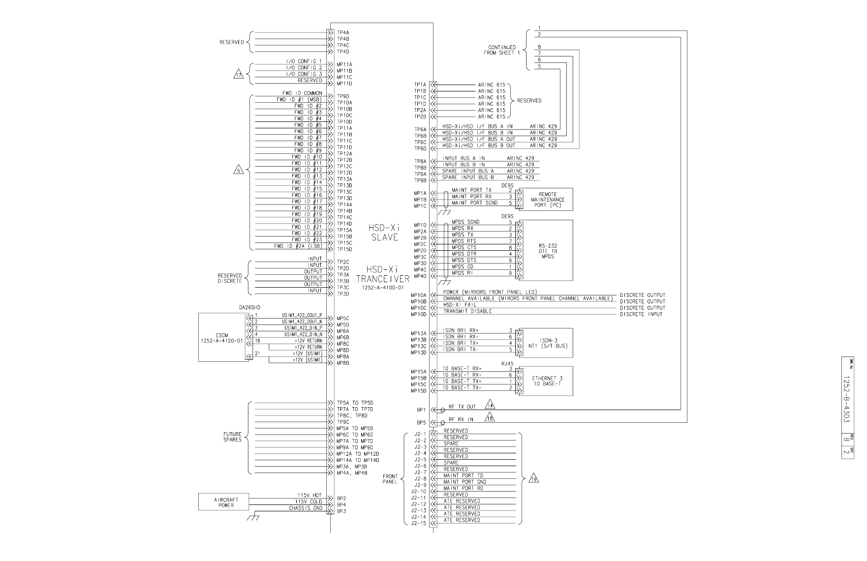
Figure 3-7. System Interconnection Diagram HSD-440 Network Mode (HSD-Xi),
1252-B-4303 Rev. B00, (Sheet 1 of 4) ..................................................................................... 3-15
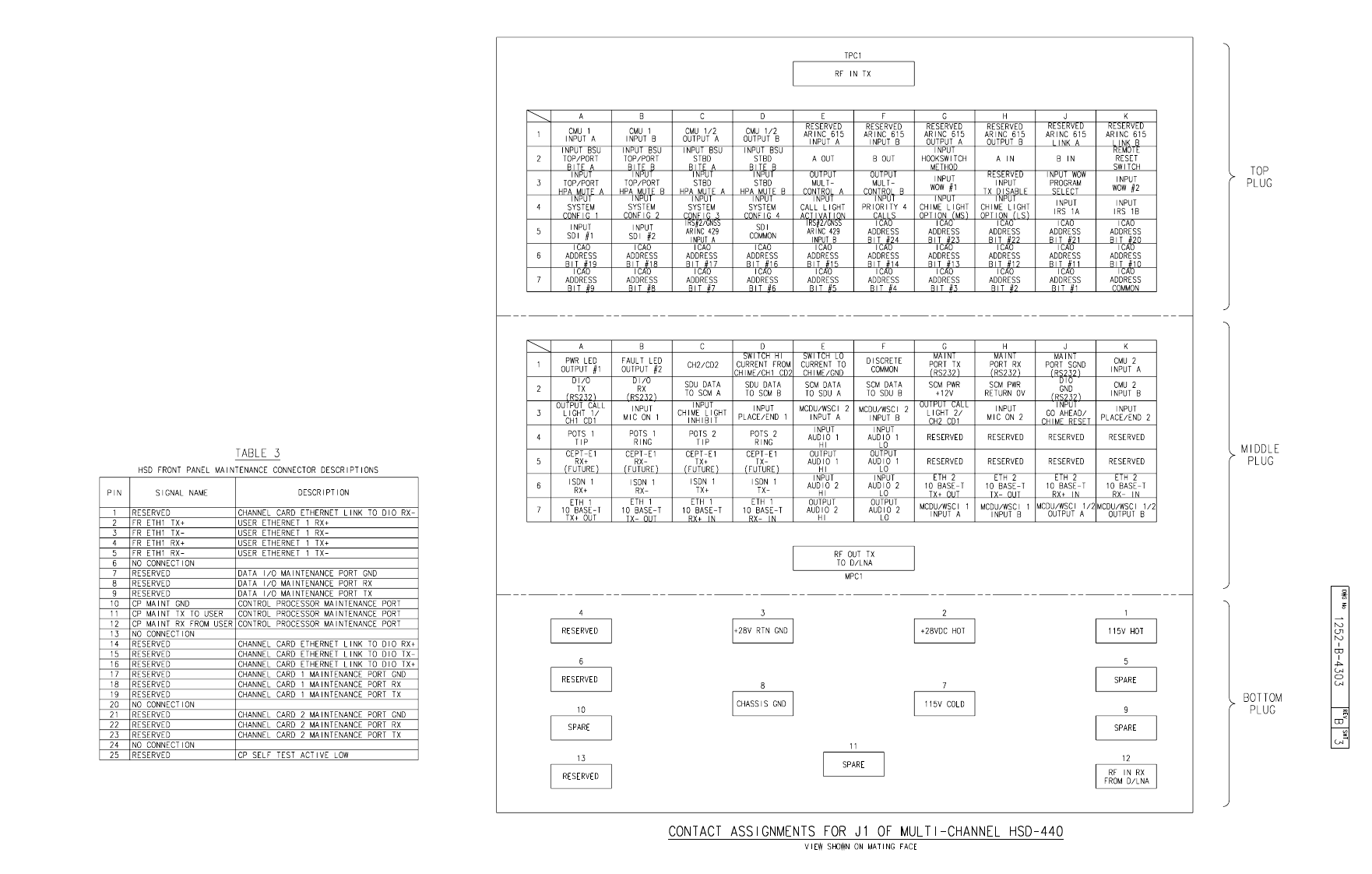
Figure 3-8. System Interconnection Diagram HSD-440 Network Mode (HSD-Xi),
1252-B-4303 Rev. B00, (Sheet 2 of 4) ..................................................................................... 3-17
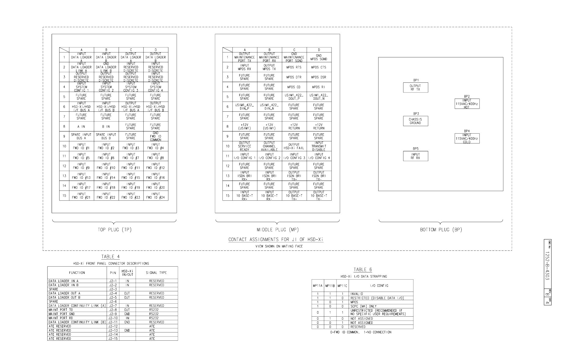
Figure 3-9. System Interconnection Diagram HSD-440 Network Mode (HSD-Xi),
1252-B-4303 Rev. B00, (Sheet 3 of 4) ..................................................................................... 3-19
Figure 3-10. System Interconnection Diagram HSD-440 Network Mode (HSD-Xi),
1252-B-4303 Rev. B00, (Sheet 4 of 4) ..................................................................................... 3-21
Figure A-1 Satellite ORs ............................................................................................................. A-1
Figure A-2 Inmarsat I3 Satellite Beam Coverage—Composite Map........................................... A-2
Figure A-3 Inmarsat I-3 Satellite Beam Coverage—OR Maps ................................................... A-3
Figure A-4 I-4 Satellite Coverage Map ....................................................................................... A-4
Figure F-1 Network Connections Window .................................................................................. F-1
Figure F-2 New Connection Wizard............................................................................................ F-2
Figure F-3 Network Connection Type Page ............................................................................... F-2
Figure F-4 Getting Ready Page.................................................................................................. F-3
Figure F-5 Internet Connection Page ......................................................................................... F-3
Figure F-6 Connection Name Page ............................................................................................ F-4
Figure F-7 Connection Availability Page..................................................................................... F-4
Figure F-8 Internet Account Information Page............................................................................ F-5
Figure F-9 Completing the New Connection Wizard Page ......................................................... F-5
Figure F-10 Connect Dialog Box ................................................................................................ F-6
Figure F-11 Properties Dialog Box ............................................................................................. F-6
SYSTEM DESCRIPTION, INSTALLATION, AND MAINTENANCE MANUAL
eNfusion™ HSD-X and HSD-Xi High-speed Data Terminal
23-15-30 TC-6
8 MAY 09
Blank Page
SYSTEM DESCRIPTION, INSTALLATION, AND MAINTENANCE MANUAL
eNfusion™ HSD-X and HSD-Xi High-speed Data Terminal
23-15-30 TC-7
8 MAY 09
LIST OF TABLES
Table 1-1 HSD-Xi Characteristics and Specifications............................................................... 1-5
Table 1-2 HSD-Xi Terminal Environmental Characteristics....................................................... 1-5
Table 1-3 Discrete Outputs........................................................................................................ 1-7
Table 1-4 Front Panel LEDs ...................................................................................................... 1-8
Table 1-5 HSD-Xi Maintenance Port Pin Description ................................................................ 1-9
Table 3-1 HSD-Xi Input/Output Strapping ................................................................................. 3-5
Table E-1 Inmarsat Cause Code Definitions ............................................................................. E-1
SYSTEM DESCRIPTION, INSTALLATION, AND MAINTENANCE MANUAL
eNfusion™ HSD-X and HSD-Xi High-speed Data Terminal
23-15-30 TC-8
8 MAY 09
Blank Page

SYSTEM DESCRIPTION, INSTALLATION, AND MAINTENANCE MANUAL
eNfusion™ HSD-X and HSD-Xi High-speed Data Terminal
23-15-30 INTRO-1
8 MAY 09
INTRODUCTION
1. General
This manual provides the specifications, principles of operation, and information necessary
to install an eNfusion™ HSD-Xi terminal, and the eNfusion™ External Subscriber
Configuration Module (ESCM).
2. How This document is Organized
The information is presented in the following chapters:
•System Description
•System Operation
•Installation
•Test and Fault Isolation
•Maintenance and Repair
•Appendix A: Inmarsat Satellite Beam Coverage
•Appendix B: Troubleshooting Checklist
•Appendix C: Installation Planning Checklist
•Appendix D: Installation Checklist
•Appendix E: Inmarsat Cause Codes
•Appendix F: Setting Up SBB
NOTE: An Illustrated Parts List is not included with this manual.
Only qualified avionics personnel, knowledgeable in the technical and safety issues related
to the installation of aircraft communications equipment, should perform the installation
procedures provided in this manual.
This manual includes general installation guidelines only; it is not intended to provide specific
procedures for every type of installation.
If necessary, the information in this manual will be revised. Before attempting the installation
procedures presented in this manual, verify that you have a complete and up-to-date release
of this document.
NOTE: Depending on the version of software and configuration mode of installation of the
the HSD-Xi terminal, the actual (live) system messages, such as dialog boxes and
screen displays, may differ slightly from the examples in this manual.
SYSTEM DESCRIPTION, INSTALLATION, AND MAINTENANCE MANUAL
eNfusion™ HSD-X and HSD-Xi High-speed Data Terminal
23-15-30 INTRO-2
8 MAY 09
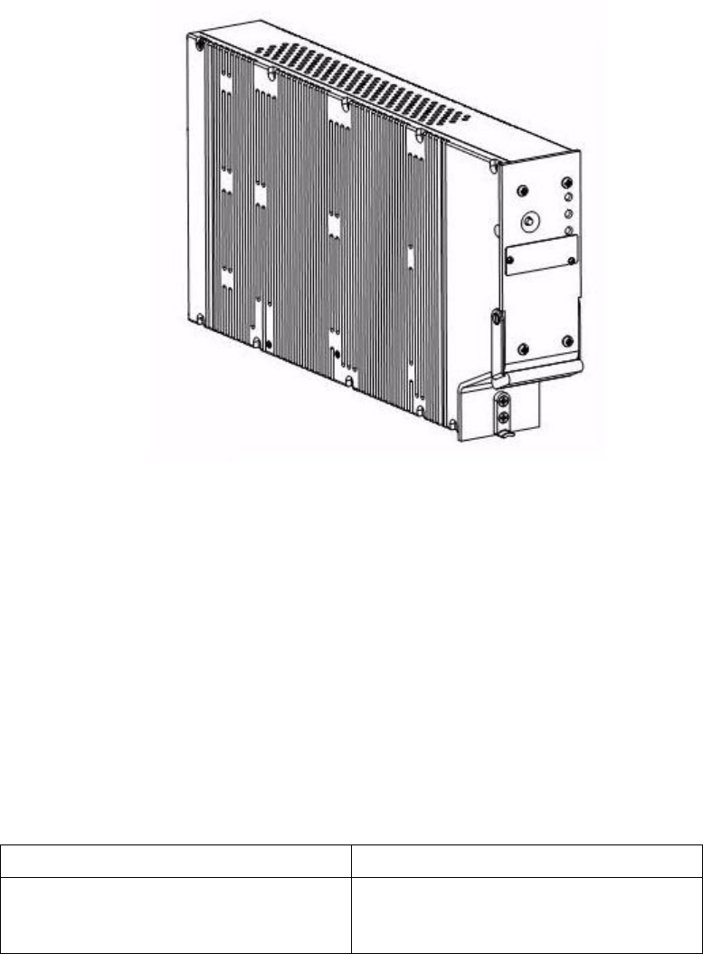
3. Illustration of Equipment
Figure INTRO-1 HSD-Xi Terminal
4. Product Terms and Conditions
As stipulated in the Terms and Conditions of Sale, which accompanied the Product, EMS
SATCOM shall not at any time be liable for the activation, continuation, or cancellation of
satellite airtime services relating to the Product nor be responsible for any Product-related
airtime or network charges, however incurred. In the event EMS SATCOM is charged network
or airtime fees relating to the customer’s use of the Product, the customer shall immediately
upon notification by EMS SATCOM reimburse EMS SATCOM in full for such charges.
5. Reference Documents
Document Title EMS SATCOM Publication Number
Guidance for Aircraft Electrical Power
Utilization and Transient Protection ARINC 741. ARINC Report 413A—
Attachment 3-2, Wire Shielding and
Grounding Requirements and Appendix 7
SYSTEM DESCRIPTION, INSTALLATION, AND MAINTENANCE MANUAL
eNfusion™ HSD-X and HSD-Xi High-speed Data Terminal
23-15-30 INTRO-3
8 MAY 09
6. Acronyms and Abbreviations
The following acronyms and abbreviations are used in this document.
ACSE Access Control and Signalling Equipment
AERO Aeronautical
AMBE Advanced Multi-Band Excitation
AORE Atlantic Ocean Region-East
AORW Atlantic Ocean Region-West
BGAN Broadband Global Area Network
BITE Built-In Test Equipment
bps Bits per second
C/No Carrier-to-Noise
DLNA Diplexer/Low-Noise Amplifier
EIRP Effect Isotropic Radiated Power
ESCM External Subscriber Configuration Module
ESD Electrostatic Discharge
EST Eastern Standard Time
FAA Federal Aviation Authority
FWD ID Forward ID
GES Ground Earth Station
GND Ground
HGA High-gain Antenna
HPA High Power Amplifier
Hz Hertz
I/O Input/Output
ICAO International Civil Aviation Organization
IMN Inmarsat Mobile Number
INS Inertial Navigational System
IOR Indian Ocean Region
IRS Inertial Reference System
ISDN Integrated Services Digital Network
ISN Inmarsat Serial Number
ISP Inmarsat Service Providers
ISP Internet Service Provider
JAA Joint Aviation Authorities
kbps Kilobits per Second
SYSTEM DESCRIPTION, INSTALLATION, AND MAINTENANCE MANUAL
eNfusion™ HSD-X and HSD-Xi High-speed Data Terminal
23-15-30 INTRO-4
8 MAY 09
LAN Local Area Network
LES Land Earth Station
LRU Line Replaceable Unit
Mbps Megabit per second
MCDU Multipurpose Control Display Unit
MCU Modular Concept Unit
MES Mobile Earth Station
MPDS Mobile Packet Data Services
MPU Maintenance Port Utility
ms Millisecond
MSN Mobile Serial Number
MSN Multiple Subscriber Number
O&I Outline and Installation Diagram
OA Other Antenna
ORR Ocean Region Registration
ORT Owner Requirements Table
PN Part Number
POR Pacific Ocean Region
POTS Plain Old Telephone System
PPP Point-to-Point Protocol
PPPoE Point-to-Point Protocol over Ethernet
RAM Random Access Memory
RF Radio Frequency
RFU Radio Frequency Unit
ROM Read-only Memory
RTN Return
Rx Receive
SBB SwiftBroadband
SCPC Single Channel per Carrier
SDI Source/Destination Identification
STU Secure Telephone Unit
Tx Transmit
USIM Universal Subscriber Identity Module
VHF very high frequency
WOW Weight on Wheels
SYSTEM DESCRIPTION, INSTALLATION, AND MAINTENANCE MANUAL
eNfusion™ HSD-X and HSD-Xi High-speed Data Terminal
23-15-30 INTRO-5
8 MAY 09
7. Safety Advisories
Warnings, cautions, and notes in this manual provide the reader with the following information:
• A WARNING describes an operation, procedure, or condition that, if not obeyed, could
cause injury or death.
• A CAUTION describes an operation, procedure, or condition that, if not obeyed, could
cause damage to the equipment.
• A NOTE provides supplementary information or explanatory text that makes it easier to
understand and perform procedures.
All personnel who install, operate, and maintain the HSD-Xi terminal and associated test
equipment must know and obey the safety precautions listed below. The procedures provided
in this manual assume that the person performing installation or maintenance tasks is familiar
with and obeys standard aviation shop and safety practices.
The general safety advisories include the following:
WARNING: SERVICE PERSONNEL MUST OBEY STANDARD SAFETY
PRECAUTIONS, SUCH AS WEARING SAFETY GLASSES, TO PREVENT
PERSONAL INJURY WHILE INSTALLING OR PERFORMING SERVICE
ON THIS TERMINAL.
WARNING: ASSOCIATED SATELLITE COMMUNICATIONS EQUIPMENT RADIATES
HIGH FREQUENCY RADIATION AND POSES A RADIATION HAZARD
OF 1.6 GHZ. SERVICE PERSONNEL MUST EXERCISE CARE TO KEEP
CLEAR OF THE ANTENNA'S BEAM WHILE PERFORMING
OPERATIONAL TESTS OR INSTALLATION VERIFICATION
PROCEDURES.
DO NOT APPROACH WITHIN 8 FEET (2.5 METRES) OF THE ANTENNA
DURING ANTENNA OPERATION (TRANSMISSION).
DURING ANTENNA OPERATION (TRANSMISSION), MAKE SURE THAT
PERSONNEL ARE EXPOSED TO A MINIMUM OF ANY REFLECTED,
SCATTERED, OR DIRECT BEAMS.
WARNING: TURN OFF POWER BEFORE DISCONNECTING ANY TERMINAL FROM
WIRING. DISCONNECTING THE TERMINAL WITHOUT TURNING
POWER OFF MAY CAUSE VOLTAGE TRANSIENTS THAT CAN
DAMAGE THE TERMINAL.

SYSTEM DESCRIPTION, INSTALLATION, AND MAINTENANCE MANUAL
eNfusion™ HSD-X and HSD-Xi High-speed Data Terminal
23-15-30 INTRO-6
8 MAY 09
CAUTION: THIS EQUIPMENT INCLUDES ITEMS THAT ARE ELECTROSTATIC
DISCHARGE SENSITIVE (ESDS) DEVICES. ESDS DEVICES ARE
SUBJECT TO DAMAGE BY EXCESSIVE LEVELS OF VOLTAGE AND/OR
CURRENT. THE LOW-ENERGY SOURCE THAT MOST COMMONLY
DESTROYS ESDS DEVICES IS THE HUMAN BODY, WHICH, IN
CONJUNCTION WITH NONCONDUCTIVE GARMENTS AND FLOOR
COVERINGS, GENERATES AND RETAINS STATIC ELECTRICITY. TO
ADEQUATELY PROTECT ESDS DEVICES, THE DEVICE AND
EVERYTHING THAT CONTACTS IT MUST BE BROUGHT TO GROUND
POTENTIAL BY PROVIDING A CONDUCTIVE SURFACE AND
DISCHARGE PATHS. USE STANDARD INDUSTRY PRECAUTIONS TO
KEEP RISK OF DAMAGE TO A MINIMUM WHEN TOUCHING,
REMOVING, OR SERVICING THE EQUIPMENT.
SYSTEM DESCRIPTION, INSTALLATION, AND MAINTENANCE MANUAL
eNfusion™ HSD-X and HSD-Xi High-speed Data Terminal
23-15-30 1-1
8 MAY 09
SYSTEM DESCRIPTION
This section includes basic information about the HSD-Xi terminal, and includes the following
sections:
•Inmarsat System Overview
•Equipment Overview
•Equipment Specifications
•Software Description
•Mechanical Description
•Electrical Description
•HSD-Xi Terminal System Interfaces
•User Interfaces
•Initiated Self-Test
1. Inmarsat System Overview
The satellite communication system includes global satellite networks, LESs, and Mobile Earth
Stations (MESs).
The LES is the part of the satellite communication system that is on the ground. These
numerous, international stations are responsible for routing voice and data calls from the MES
to their destinations around the world.
The MES is the part of the satellite communication system that is on the aircraft. This station
includes the following components:
•HSD terminal
• Antenna subsystem
• Cabin communications system
• Analog connected telephones
• Cockpit voice system
• Other aircraft avionics
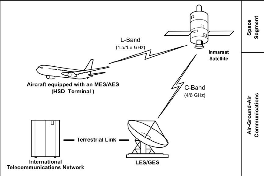
Figure 1-1 illustrates a simplified satellite communications system.
SYSTEM DESCRIPTION, INSTALLATION, AND MAINTENANCE MANUAL
eNfusion™ HSD-X and HSD-Xi High-speed Data Terminal
23-15-30 1-2
8 MAY 09
Figure 1-1 Simplified Aeronautical Satellite Communications System
Satellite communication systems provide users with long-range voice and data communication
by accessing global satellite and ground communications networks.
Inmarsat is an international organization that operates and maintains multiple geostationary
satellites and satellite networks. The satellites that provide Swift64 services are called I-3
satellites. Each satellite is located over an Ocean Region (OR); the current OR names are:
• Atlantic Ocean Region-East (AOR-E)
• Atlantic Ocean Region-West (AOR-W)
• Indian Ocean Region (IOR)
• Pacific Ocean Region (POR)
These satellites provide worldwide telecommunication services for aviation, shipping, and
land-mobile terminal users. The satellites connect to ground telecommunication systems
through the LES/GES.
The satellites that provide SBB services are called I-4 satellites. At the time of publishing,
three I-4 satellites provide SBB services: Americas (98W), EMEA (25E) and Asia-Pacific
(143.5E).
The HSD-Xi terminal extends the communication functions provided by other HSD terminals.
It does not communicate with the satellite network on its own. It must be installed with a HSD
to communicate with the satellite network.
SYSTEM DESCRIPTION, INSTALLATION, AND MAINTENANCE MANUAL
eNfusion™ HSD-X and HSD-Xi High-speed Data Terminal
23-15-30 1-3
8 MAY 09
2. Equipment Overview
This section briefly describes the HSD-Xi terminal, the ESCM and the SwiftBroadband (SBB)
services supported by the HSD-Xi terminal.
A. HSD-Xi
The HSD-Xi terminal cannot communicate with the satellite network on its own. It extends
the communication functions provided by HSD-440 terminals. The HSD-440 terminal
controls the power available to the HSD-Xi terminal and makes channels available to the
HSD-Xi terminal. The HSD-440 terminal also allocates resources according to the needs
of other equipment in the aircraft, such as communication and safety related equipment.
The HSD-Xi terminal works in conjunction with an HSD-440 terminal to provide one
additional channel of Swift64 services and SBB services.
B. ESCM
The ESCM connects to the HSD-Xi terminal, and contains one standard USIM card that
provides secure subscriber information for billing, and stores the Inmarsat network
parameters that are required for SBB services.
In the ESCM, the microprocessor chip reads the USIM card, and the RS-422 serial
transceiver chip communicates with the channel card in the HSD-Xi terminal.
The ESCM also contains a temperature control system and heating elements because
the operating temperature range of the USM cards is smaller than the HSD-Xi terminal.
When the temperature of the USIM cards is below their operational limit, the ESCM turns
on the heaters and holds the microprocessor chips in reset mode until the USIM cards
reach their operating temperature. SBB services are available after the ESCM has
warmed up and the warm-up time for the ESCM may be up to ten minutes.
If the HSD-Xi detects a fault when it is connected to the ESCM, the HSD-Xi creates an
event log entry.
C. SBB Services
SBB is high-speed satellite communication network to which satellite communication
terminals can connect from any location within view of a satellite. The SBB network and
its terminals enable the simultaneous use of voice and data services.
SBB services are defined by QoS, which assigns a priority to data traffic and guarantees
a certain bandwidth according to that priority. There are two QoSs: streaming IP and
standard IP.
(1) SBB Packet-Switched Services
(a) Streaming IP
Streaming IP service can transfer data at a guaranteed rate of up to 128 Kbps.
Data can be transferred at the rates: 32 kbps, 64 kbps, or 128 kbps streaming
service. The cost of streaming IP services is based on the amount of time the
connection is active.
SYSTEM DESCRIPTION, INSTALLATION, AND MAINTENANCE MANUAL
eNfusion™ HSD-X and HSD-Xi High-speed Data Terminal
23-15-30 1-4
8 MAY 09
(b) Standard IP
Standard IP services, also known as Background IP services, can transfer data
at a rate of up to 432 Kbps. Typical throughput rates range between 100 to 300
kbps. This bandwidth is shared by all users on a channel, and users may
experience lower transfer rates when multiple users are transferring data.
Standard IP is the recommended service for using the Internet, e-mail, and VPN
applications that have moments of high traffic followed by low or no traffic. The
cost of standard IP services is based on the amount of data transferred.
(2) SBB Circuit-Switched Services
SBB supports one 64 Kbps ISDN bearer to provide the following services:
• AMBE+2 voice
• 56 kbps RDI
• 64 kbps UDI
• 3.1 KHz audio
The cost of circuit-switched services is based on the amount of time the connection
is active.
(3) Primary and Secondary PDP Contexts
A PDP context defines connection aspects such as routing, QoS, security, and billing
between the HSD-Xi terminal and a core network.
SBB requires a primary PDP context to establish IP services. Therefore, it is activated
first. A primary PDP context is associated with a unique IP address.
A secondary PDP context can only be established after a primary PDP context has
been activated. Secondary PDP contexts can be used when some applications
require different QoS profiles. For example, a primary Background PDP context can
provide Internet access and e-mail, and a secondary streaming 128 kbps PDP context
can provide video conferencing.
A secondary PDP context has the same IP address as the primary context, but it can
have different QoS profiles.
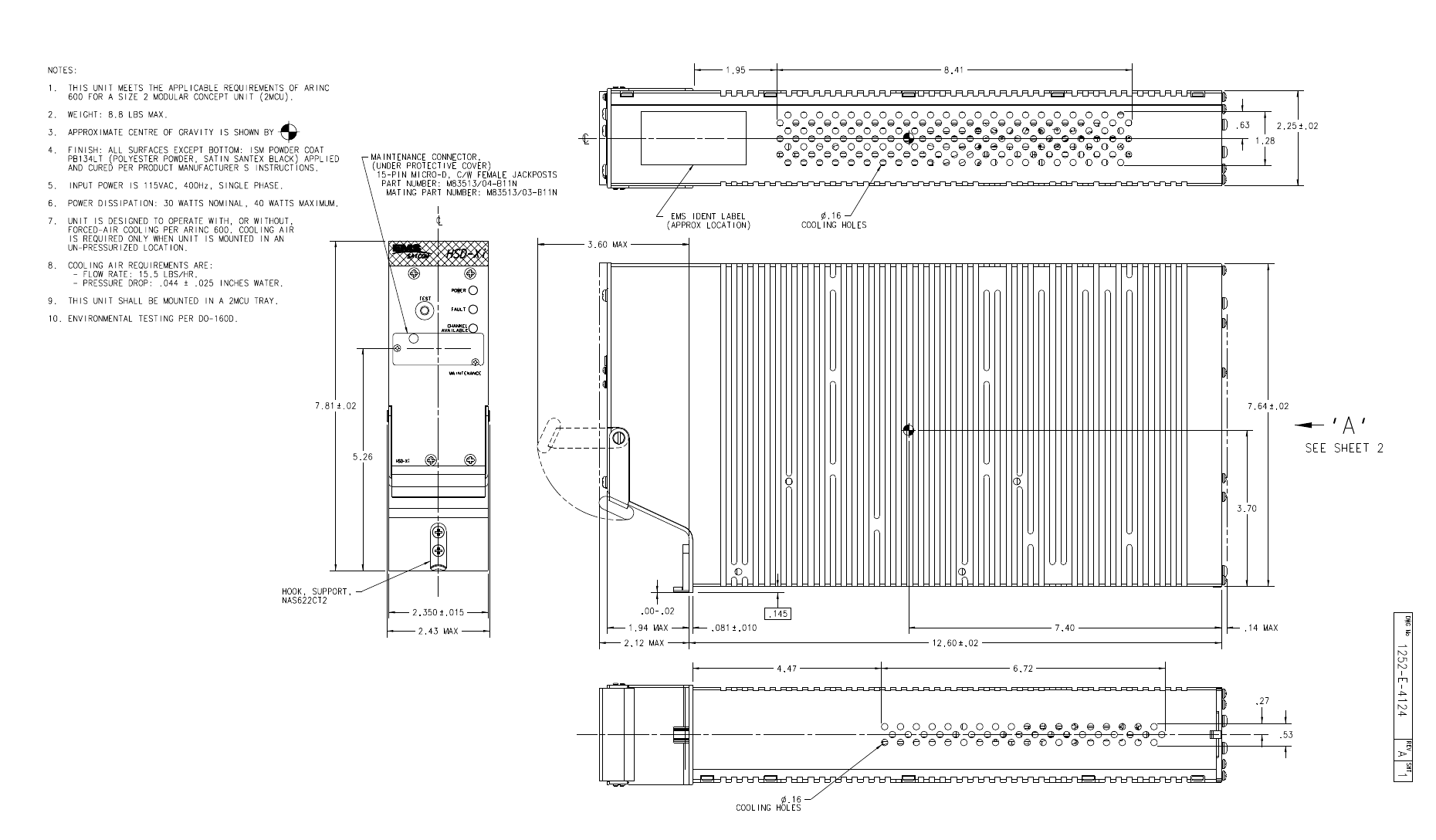
3. Equipment Specifications
The HSD-Xi is a 2-MCU size terminal with mounting requirements that meet the ARINC
600 specification. The front panel has one, female, micro-D type connector for data loading
and monitoring of the unit.
SYSTEM DESCRIPTION, INSTALLATION, AND MAINTENANCE MANUAL
eNfusion™ HSD-X and HSD-Xi High-speed Data Terminal
23-15-30 1-5
8 MAY 09
Table 1-1 lists the physical characteristics and equipment specifications for the HSD-Xi
terminal.
Table 1-1 HSD-Xi Characteristics and Specifications
Characteristic Specification
Physical Characteristics
Size 2 MCU ARINC 600-10 Form Factor
Weight 8.8 lbs maximum
Cooling Air Unit capable of continuous duty cycle operation, with
or without forced air-cooling provided, as per ARINC
600 specifications. Refer to 1110-E-0401.
Electrical Characteristics
Power dissipation 34 W
Input Power 115 V ac, 400Hz, 75 va
Input frequency range 1530.0 to 1559.9 MHz
Output frequency range 1626.5 to 1660.5 MHz
Receiver input impedance 50 ohms
Transceiver output
impedance 50 ohms
Input level operational -107 dBm to -47 dBm
Input level no damage +10 dBm
External Interfaces
Crosstalk bus ARINC 429 high-speed (100 kbps) data bus
Maintenance port RS-232
data loader front and rear
connector
RS-232 serial bus supports 57.6 kbps data load
capacity
ISDN user interface 64 kbps ISDN Euro input and output
Ethernet 10BASE-T (full and half duplex)
Table 1-2 lists the environmental specifications for the HSD-Xi terminal.
Table 1-2 HSD-Xi Terminal Environmental Characteristics
Characteristic Specification/Category
Temperature and Altitude A4 without cooling air, C4 with
cooling air
Low Operating Temperature -40 ºC (A4), -40 ºC (C4)
High Operating Temperature + 55 ºC (A4), +70 ºC (C4)
Altitude Maximum operating altitude:
15,000 ft (A4), 55,000ft (A5)

SYSTEM DESCRIPTION, INSTALLATION, AND MAINTENANCE MANUAL
eNfusion™ HSD-X and HSD-Xi High-speed Data Terminal
23-15-30 1-6
8 MAY 09
4. Software Description
This section describes the software specifications and operational software components of
HSD-Xi terminal.
A. Software Specifications
The software meets the Swift64 to Level E DO-178B standard.
B. Operational Software Part Number
The HSD-Xi terminal software part number is L1-1252-42001.
5. Mechanical Description
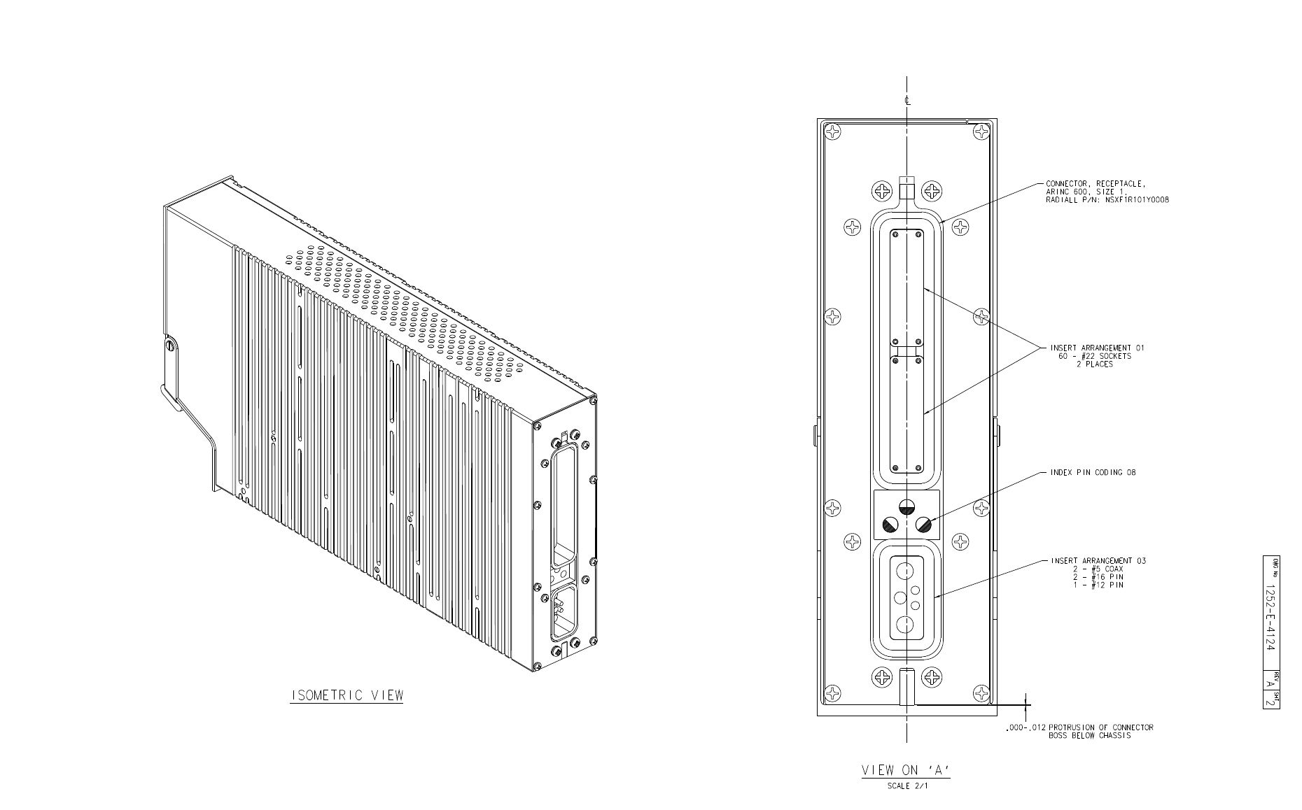
The rear connector complies with ARINC 600, shell size 1. The top and middle connectors
have 60 number 22 pins, and the bottom connector has two number 16 pins, one number 12
pin, and two RF connections.
Loss of cooling Y
Temperature B
Humidity A
Shock B
Vibration SB
Explosion Proofness E
Water Proofness X
Fluids Susceptibility X
Sand and dust X
Fungus Resistance F
Salt Spray X
Magnetic Effect Z
Power Input A
Voltage Spike A
Audio Frequency A
Induced Signal C
RF Susceptibility RR
Emission of RF Energy M
Lightning Induced Transient Susceptibility A3E3
Lightning Direct Effects X
Table 1-2 HSD-Xi Terminal Environmental Characteristics (Continued)
Characteristic Specification/Category

SYSTEM DESCRIPTION, INSTALLATION, AND MAINTENANCE MANUAL
eNfusion™ HSD-X and HSD-Xi High-speed Data Terminal
23-15-30 1-7
8 MAY 09
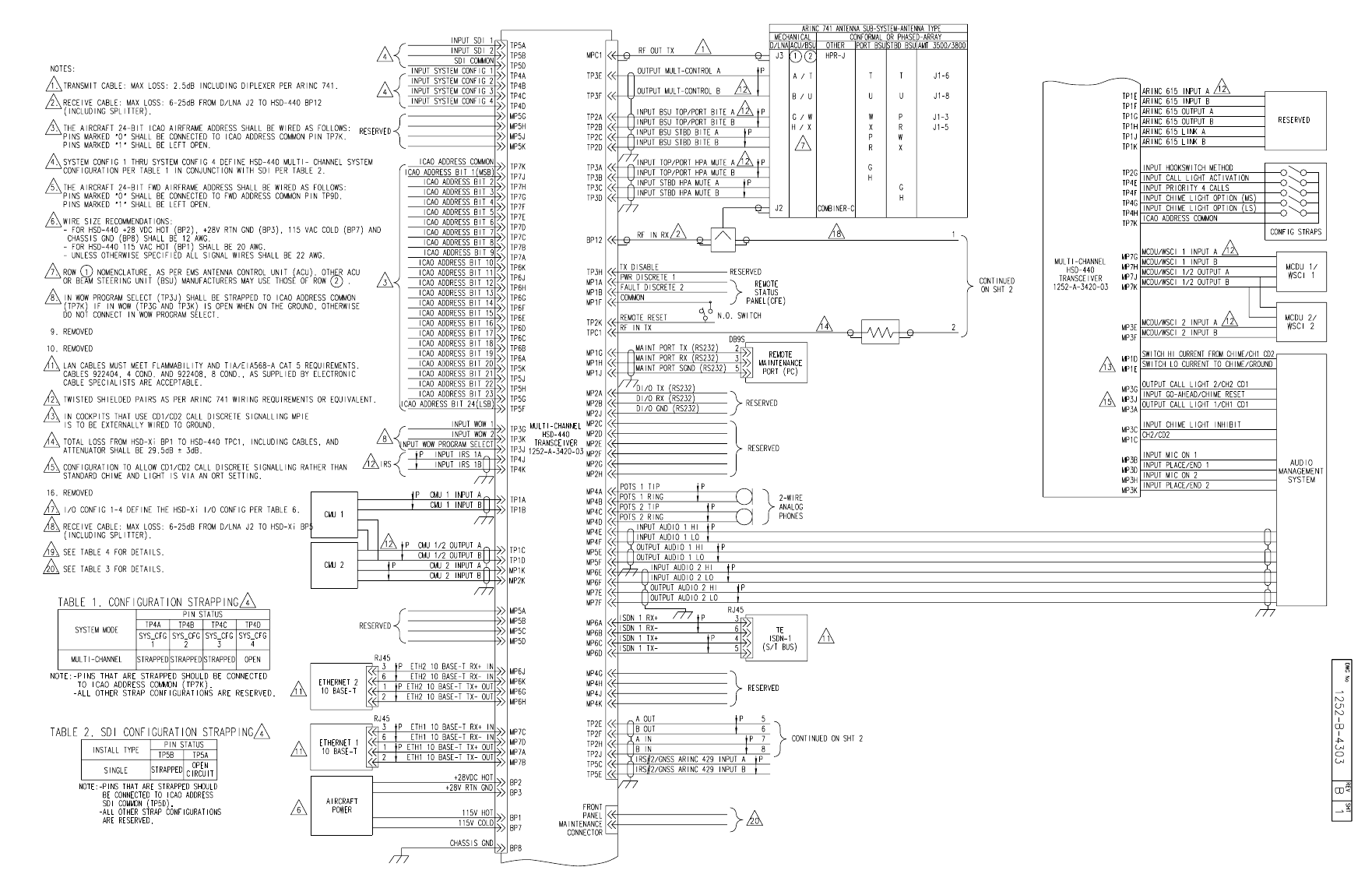
Figure 3-7 to Figure 3-10 present the HSD-Xi and network mode HSD terminals connection
details.
6. Electrical Description
See Figure 3-7 to Figure 3-10 for installation information.
7. HSD-Xi Terminal System Interfaces
This section briefly describes the external HSD-Xi terminal system interfaces connections to
other systems on the aircraft. For information on interface connections available to aircraft
passengers, see "Installation" on page 3-1.
A. Forward IDs
Forward IDs identify the terminal to the Inmarsat Network.
The 24-bit Forward ID strap pins on the ARINC 600 connector form part of the Inmarsat
Serial Number (ISN). The ISN consists of the type approval number and the Forward ID.
Each Forward ID is associated with Inmarsat Mobile Numbers that a user on the ground
dials to reach the terminal on the aircraft. There is a unique Inmarsat Mobile Number for
each of the service types.
B. Discrete Outputs
The discrete outputs indicate the HSD-Xi terminal status.
Table 1-3
Discrete Outputs Description
(when illuminated)
MP10 A Power This output is illuminated if the unit has power. It
flashes if the HSD-Xi has an active call.
MP10C HSD-Xi Fail This output is illuminated if the HSD-Xi has a fault.
MP10 B - Channel Available This output is illuminated when the HSD-Xi is
registered and attached to a network operating in
GAN or BGAN mode, or if the HSD terminal has
allocated power to the HSD-Xi.
Discrete Outputs
C. Front Panel LEDs
These fault conditions illuminate the LED on the front panel of the HSD-Xi:

SYSTEM DESCRIPTION, INSTALLATION, AND MAINTENANCE MANUAL
eNfusion™ HSD-X and HSD-Xi High-speed Data Terminal
23-15-30 1-8
8 MAY 09
Table 1-4
LED LED Color Description
(when illuminated)
Top Green MP10 A Power - This output is illuminated if the
unit has power. It flashes if the HSD-Xi has an
active call.
Middle Red MP10C HSD-Xi Fail - This output is illuminated if
the HSD-Xi has a fault.
Bottom Green MP10 B - Channel Available - This output is
illuminated when the HSD-Xi is registered and
attached to a network operating in GAN or BGAN
mode, or if the HSD terminal has allocated power
to the HSD-Xi.
Front Panel LEDs
D. Fault Conditions
The HSD-Xi terminal can indicate one of the following fault conditions. Upon detection of
a fault condition, the red colored Fault LED is illuminated.
• Channel card fault
• HPA fault
• Internal ROM fault
• Internal RAM fault
• Over temperature fault
E. HSD-Xi Maintenance Port
The HSD-Xi maintenance port provides access to the HSD-Xi maintenance utility which
is a program that can monitor the HSD-Xi and test HSD-Xi functions.
The HSD-Xi maintenance port utility is also used to update the HSD-Xi software. For
information on how to use the maintenance port utility in console mode, see Connecting
to the HSD-Xi terminal through the network mode HSD Console Mode.
The HSD-Xi maintenance port connector is a female, micro-D type M83513/04-B11N.
The rear middle plug of the HSD-Xi terminal provides remote access to the maintenance
port utility, see the interconnection diagram in Figure 3-9.

SYSTEM DESCRIPTION, INSTALLATION, AND MAINTENANCE MANUAL
eNfusion™ HSD-X and HSD-Xi High-speed Data Terminal
23-15-30 1-9
8 MAY 09
Table 1-5
Label (Octal) Pin HSD-Xi In/Out Signal Type
Data Loader in A 1 - Reserved
Data Loader in B 2 - Reserved
Spare 3 - -
Data Loader out A 4 - Reserved
Data Loader out B 5 - Reserved
Spare 6 - -
Data Loader
Continuity Link (A) 7 - Reserved
Maint port TD 8Out RS-232
Maint port GND 9GND RS-232
Maint port RD 10 In RS-232
Data Loader
Continuity Link (B) 11 -Reserved
ATE reserved 12 -ATE
ATE reserved 13 GND ATE
ATE reserved 14 -ATE
ATE reserved 15 -ATE
HSD-Xi Maintenance Port Pin Description
8. User Interfaces
The HSD-Xi terminal has the following user connections.
A. Ethernet Data Interface
The HSD-Xi terminal has one 10BASE-T Ethernet data interface.
B. ISDN Interface
The HSD-Xi terminal has one ISDN bearer channel available through the ISDN interface.
C. Maintenance Port Interface
The HSD-Xi terminal has one maintenance port, located on the front panel of the terminal.
It provides remote access available through the rear ARINC 600 connector.
NOTE: Access to maintenance functions of the network mode HSD and the HSD-Xi
terminal in flight is only available through the remote access port.
The maintenance port provides the physical connection to a password-protected MPU
that provides a system interface for users or service personnel who need to upgrade,
monitor, or troubleshoot the system.
SYSTEM DESCRIPTION, INSTALLATION, AND MAINTENANCE MANUAL
eNfusion™ HSD-X and HSD-Xi High-speed Data Terminal
23-15-30 1-10
8 MAY 09
• A standard VT100 compatible terminal or computer running an emulator
program such as HyperTerminal©, ProComm (PCPLUS)©, or another serial
communication package provides the user interface to the HSD-Xi terminals
MPU. Configure the connection as follows:
• Bits per second—19200
• Data bits—8
• Parity—none
• Stop bits—1
• Flow control—none
The HSD-Xi terminals supports two different end user access levels within the
maintenance port architecture: End User and Field Representative.
(1) End User Access: Level 1
Password: menu
This limited-access level is for anyone without technical training on the product. It
provides read-only access to help users diagnose problems with the assistance of
product support personnel.
(2) Field Representative Access: Level 2
Password: maint
This level is for trained installers and product support personnel. This access level
supports read and limited write capabilities. Users are able to disable/mask/clear
faults, change satellite or LES preferences, view and modify certain EEPROM
parameters, and perform other maintenance or upgrade functions.
"Test and Fault Isolation" on page 4-1 provides a detailed description of the two levels
of user access and the menus, report selections, functions, and system diagnostic
procedures of the HSD-Xi terminals MPU.
9. Initiated Self-Test
The initiated self-test occurs during the power up sequence, or when you press and hold down
the TEST button on the front panel of the terminal for 100 milliseconds or more.
SYSTEM DESCRIPTION, INSTALLATION, AND MAINTENANCE MANUAL
eNfusion™ HSD-X and HSD-Xi High-speed Data Terminal
23-15-30 2-1
8 MAY 09
SYSTEM OPERATION
This section describes how to register and activate the HSD-X and HSD-Xi terminals. For
information on how to configure the system, see Configuring the system.
1. Registering and Activating Terminals
Registering and activating an HSD-X and HSD-Xi terminal includes the following:
•Preparing Terminal Information
•Choosing Service Providers
•Registering Terminals
A. Preparing Terminal Information
Before installing the HSD-X and HSD-Xi terminals, obtain an ISN and identify the Swift64
terminal type.
(1) Obtaining ISNs
EMS SATCOM provides ISNs for the HSD-X and HSD-Xi terminal based on the
intended installation configuration. The last six digits of the ISN are the Forward ID.
When requesting ISNs, please have the following information available:
• End customer name, including contact information
• Purchase order number
• Tail registration number, aircraft type, and serial number of the aircraft on which
the terminal is being installed
• Serial number of the HSD and the HSD-Xi terminal(s)
• Intended installation configuration mode (Stand-Alone or non-Stand-Alone)
EMS SATCOM Product Support is available Monday to Friday from 8 am to 5 pm
(EST). On-call support is available outside business hours, Eastern Standard Time.
Contact information for EMS SATCOM:
Product Support 1.888.300.7415
Product Support direct 1.613.591.3086
Canada and USA toll-free Sales 1.800.600.9759
Outside Canada and USA 1.613.591.9064
Fax: 1.613.591.9120
Web: www.emssatcom.com
(2) Identifying the Swift64 Service Terminal Type
The Swift64 terminal type for all modes of HSD-X and HSD-Xi terminals is 76ES09.
Currently supported service types for HSD-400 terminals operating Swift64 are as
follows:
• 64 kbps speech
SYSTEM DESCRIPTION, INSTALLATION, AND MAINTENANCE MANUAL
eNfusion™ HSD-X and HSD-Xi High-speed Data Terminal
23-15-30 2-2
8 MAY 09
• 3.1 kHz audio
• 56 kbps data
• 64 kbps UDI
•MPDS
B. Choosing Service Providers
Contact Inmarsat for an up-to-date list of Inmarsat Service Providers using the following
contact information:
Inmarsat
99 City Road, London
EC1Y 1AX
Tel: +44 20 7728 1000
Fax: +44 20 728 1044
Customer Care
Tel: +44 20 7728 1777
Fax: +44 20 7728 1142
Email: customer_care@inmarsat.com
Web addresses: www.inmarsat.com and www.inmarsat.com/swift64/supp_ser.htm
C. Registering Terminals
Contact your Inmarsat service provider and ask for a Registration for service activation
of Aircraft Earth Station form. Use the form to register for Swift64 services.
Complete the registration form for your HSD, and your HSD-Xi terminal. You need the
following information:
• Customer information (address and contact information)
• Service provider details (obtained from your ISP)
• System and terminal information (terminal type, manufacturer, model number, serial
number of terminal)
• ISN for Swift64 services
• Aircraft information (tail number, fuselage/airframe number, manufacturer and model,
and country of registration)
• List of services required (for example, Swift64 Mobile ISDN)
To register for SBB services, request a BGAN Activation form from your service provider.

SYSTEM DESCRIPTION, INSTALLATION, AND MAINTENANCE MANUAL
eNfusion™ HSD-X and HSD-Xi High-speed Data Terminal
23-15-30 3-1
8 MAY 09
INSTALLATION
This section describes how to install HSD-Xi on an network mode HSD terminal. It includes
the following sections:
•Advisories
•Pre-Installation Inspection
•Mechanical Installation
•Electrical Installation
•Installing the HSD-Xi and ESCM
•Configuring the system
1. Advisories
Before performing any installation procedures, read the safety advisories listed in the
Introduction on page INTRO–5 of this manual.
2. Pre-Installation Inspection
Before installing a HSD-Xi terminal, conduct a pre-installation inspection of all parts to make
sure that no damage occurred during shipping:
• Unpack the HSD-Xi terminal from the shipping container(s).
• Verify that the part number displayed on the shipping box and equipment component
matches the model and part number ordered. If components are missing from the
shipment, contact the supplier or EMS SATCOM Product Support immediately and report
the problem.
• Visually inspect the terminal for any shipping damage. If any shipping damage has
occurred, contact the shipping carrier immediately and report the problem.
• Check the HSD-Xi terminal connectors for corrosion and damage. If damage is noted, do
not apply power to the terminal. Contact the supplier or EMS SATCOM Product Support
immediately to report the problem.
3. Mechanical Installation
This section describes the mechanical installation requirements for the HSD-Xi. The System
Interconnection diagrams are provided at the end of this section. Figure 3-7 to Figure 3-10
provide connection details for the HSD-Xi terminal. All foldout pages are odd-numbered and
not-backed for print production purposes.
Electronic Cable Specialists (ECS) supplies a 2-MCU ARINC 600 mounting tray, part number
200-910002-101, for installing the HSD-Xi terminal. You can contact ECS at
www.ecsdirect.com.
SYSTEM DESCRIPTION, INSTALLATION, AND MAINTENANCE MANUAL
eNfusion™ HSD-X and HSD-Xi High-speed Data Terminal
23-15-30 3-2
8 MAY 09
You need the following hardware to install the HSD-Xi terminal:
• size 1 ARINC 600 connector
• size 1 coax contacts (on HSD-440 tray)—installation specific
• size 5 coax contacts—installation specific
4. Electrical Installation
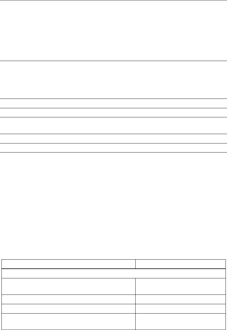
A. Cabling Notes
The system transmit loss between the network mode HSD terminal and the HSD-Xi
terminal should be as close as possible to 29.5 dB. Figure 3-1 illustrates the System
Transmit (TX) loss.
Figure 3-1 HSD-Xi System Transmit (TX) Loss
SYSTEM DESCRIPTION, INSTALLATION, AND MAINTENANCE MANUAL
eNfusion™ HSD-X and HSD-Xi High-speed Data Terminal
23-15-30 3-3
8 MAY 09
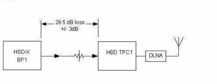
Figure 3-2 illustrates the network mode system RX loss.
Figure 3-2 System RX Loss
After you have installed the HSD-Xi, measure the cable loss. You must configure the HSD
terminal with the measured value.
B. Source/Destination Identification (SDI)
Source/Destination Identification (SDI) is provided for the beam steering unit and the
high-power amplifier (HPA) according to ARINC 741 specifications. Pins marked 0 are left
open circuit. Pins marked 1 are strapped on the airframe side of the connector to the pin
assigned as “SDI Common” (TP5D). For this High Gain Antenna (HGA) HPA application,
pin TP5B (1) should be strapped and TP5A (0) should be left open.
C. Maintenance Port Interface
Use a HSD-Xi maintenance port cable to connect directly to the front-panel maintenance
port of the HSD-Xi. The front connector maintenance port is a female, micro-D-type,
M83513/04-B11N, or equivalent connector. You can also wire a permanent connector to
the rear, middle-plug, of the ARINC-600 connector for remote access.
NOTE: The front panel and remote connections to the maintenance port of the network
mode HSD terminal and the HSD-Xi terminal cannot be used simultaneously.
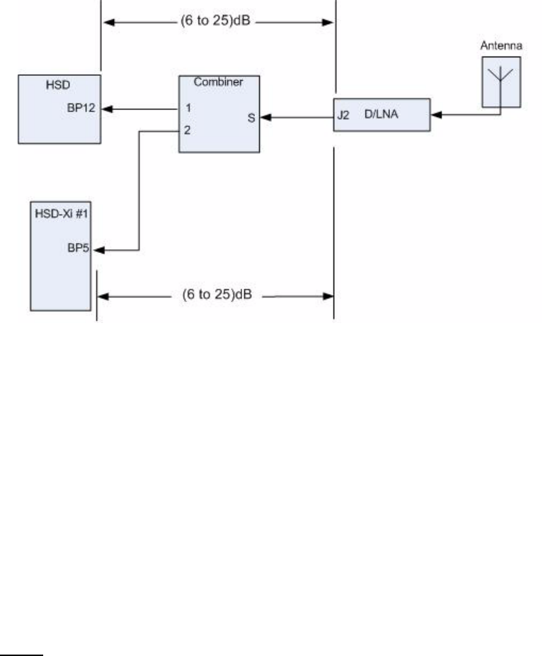
D. Remote Status Panel
The HSD-Xi remote LED shows the status of the HSD-Xi terminal. The open collector
transistors located in the HSD-Xi can drive up to 500 mA of current—so you can use either
incandescent lamps or LED circuits with the appropriate current limits. Figure 3-3
illustrates an LED powered with a 28-volt source.
SYSTEM DESCRIPTION, INSTALLATION, AND MAINTENANCE MANUAL
eNfusion™ HSD-X and HSD-Xi High-speed Data Terminal
23-15-30 3-4
8 MAY 09
Figure 3-3 HSD-Xi Remote Status LED Driver Circuits
E. System Mode Strapping
To install the HSD-440 terminal in network mode, strap these pins as follows:
• TP-4A—Strapped
• TP-4B—Strapped
• TP-4C—Strapped
• TP-4D—Open
NOTE: Pins marked 0 are signaled by strapping to ICAO Common (TP7K). Pins marked
1 are signaled by an open circuit—no connection.

SYSTEM DESCRIPTION, INSTALLATION, AND MAINTENANCE MANUAL
eNfusion™ HSD-X and HSD-Xi High-speed Data Terminal
23-15-30 3-5
8 MAY 09
F. HSD-Xi Input/Output Strapping
Table 3-1 provides the Input/Output (I/O) strapping for the HSD-Xi.
Table 3-1 HSD-Xi Input/Output Strapping
MP11A MP11B MP11C Input/Output Configuration
111Invalid
110Restricted (disable Data I/O)
101MPDS (Future)1
100SCPC (M4) only
011Unrestricted (recommended if
there are no specific user
requirements)
010Not Assigned
001Not Assigned
000Reserved
NOTE: MP11D: Reserved, 0 = FWD Address Comm
G. User Interfaces
For the HSD-Xi terminal Ethernet interface, install an RJ-45 interface connector in the
cabin area. For the ISDN interface, install an RJ-45 interface connector in the cabin area.
5. Installing the HSD-Xi and ESCM
Install the HSD-Xi and ESCM according to the System Interconnection diagrams,
Figure 3-7, Figure 3-8, Figure 3-9, and Figure 3-10.
Figure 3-4, Figure 3-5, and Figure 3-6 provide outline drawings for the HSD-Xi terminal
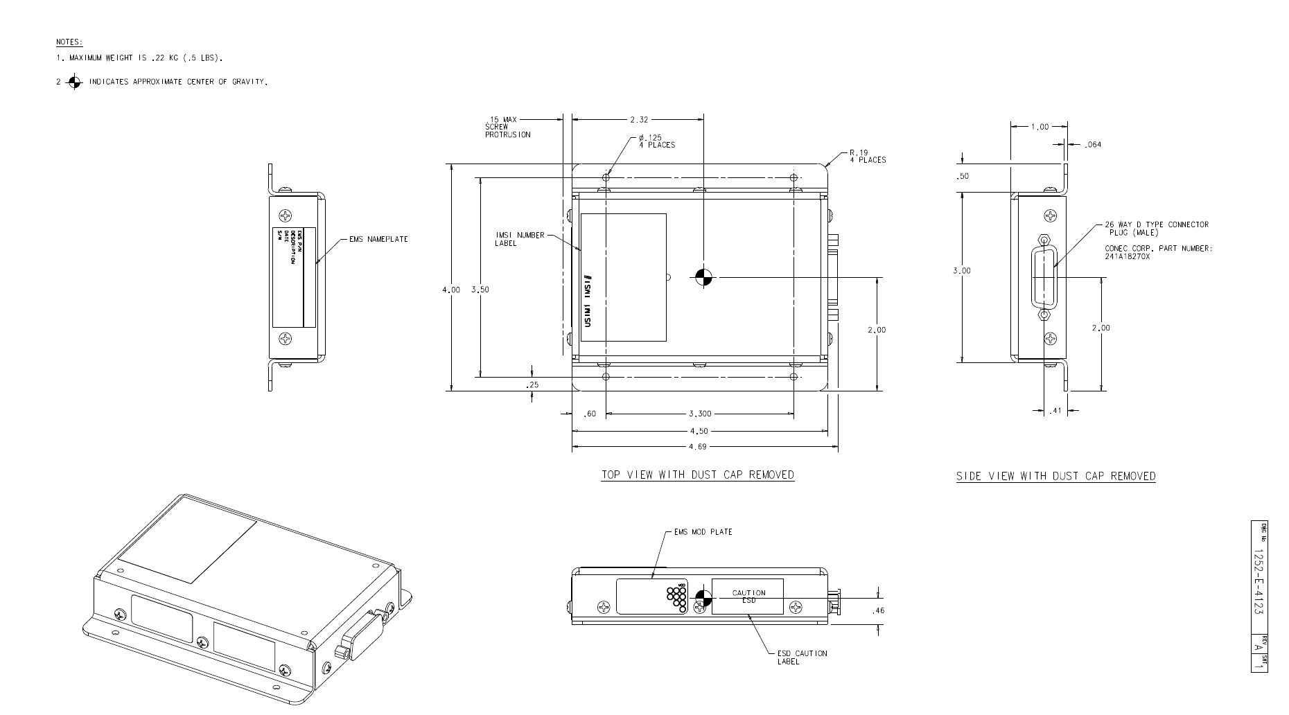
and ESCM. Mount the ESCM on a flat surface using four screws or bolts that fit the 0.125
inch holes in the mounting flange. You can install the ESCM a maximum of three meters
away from the HSD-Xi terminal.
A. Hardware and Software Requirements
You need a HSD-Xi terminal, 1252-A-4100, and an ESCM, 1252-A-4120, to use SBB
services.
You need the following software to use SBB services.
• HSD-Xi, LI-1252-42001
• HSD-440, LI-1252-33374
B. User Interfaces
You can access SBB services through the following interfaces:
• Ethernet
•ISDN
SYSTEM DESCRIPTION, INSTALLATION, AND MAINTENANCE MANUAL
eNfusion™ HSD-X and HSD-Xi High-speed Data Terminal
23-15-30 3-6
8 MAY 09
C. Creating Connections
For information on creating SBB connections, see "Setting Up SBB" on page F-1, or the
eNfusion™ HSD High-speed Data Terminal Developer’s Guide, MN-1252-13005.
6. Configuring the system
After installing the HSD-Xi, you must configure the HSD to operate in network mode, and
set the HSD-Xi cable loss.
This section contains the following procedures:
•Configuring the HSD Terminal for Network Mode
•Enabling and Disabling the Classic Channel Card
A. Configuring the HSD Terminal for Network Mode
An ORT parameter in the HSD terminal defines the cable loss between the HSD terminal
and the HSD-Xi terminal. If the HSD-440 system configuration strapping is not set to
network mode, you can set the terminal category to network mode by following these
steps.
To configure the HSD terminal to operate in network mode, follow these steps.
1. Connect a computer to the maintenance port of the HSD terminal.
2. Open a VT100 compatible terminal running an emulator program (such as
HyperTerminal, ProComm Plus, or similar) and configure the serial port for ASCII,
19200 bps, 8 bits, Parity None, 1 Stop Bit, No Flow Control.
3. Log on to the HSD terminal using the password maint.
You can navigate through the HSD menus by pressing CRTL+N to scroll through the
menus.
4. Go to Menu 3 - M parameter 16 and select 2 =HW STRAPPED VALUE.
5. Go to Menu 3 - K parameter 48 Installed and select 1=Yes.
6. Reboot the HSD terminal and the HSD-Xi terminal.
B. Enabling and Disabling the Classic Channel Card
You can operate the network mode HSD system with or without operating the Classic
channel card in the HSD terminal. Note: This feature is available in Release
LI-1252-33374 A00.
To activate or deactivate the classic channel card of the network mode HSD terminal:
1. Connect a computer to the maintenance port of the network mode HSD terminal and
go to Menu 3. To navigate to Menu 3, press CTRL + N.
2. To set control processor parameters, press k.
A list of control processor parameters appears.
SYSTEM DESCRIPTION, INSTALLATION, AND MAINTENANCE MANUAL
eNfusion™ HSD-X and HSD-Xi High-speed Data Terminal
23-15-30 3-7
8 MAY 09
3. To access the classic AERO service parameter, type 83.
A prompt to enable or disable the classic channel card appears.
4. Press 1 to enable the classic channel card.
5. Press 0 to disable the classic channel card.
6. To activate the new parameter setting, reboot the network mode HSD terminal.
SYSTEM DESCRIPTION, INSTALLATION, AND MAINTENANCE MANUAL
eNfusion™ HSD-X and HSD-Xi High-speed Data Terminal
23-15-30 3-8
8 MAY 09
Blank Page
SYSTEM DESCRIPTION, INSTALLATION, AND MAINTENANCE MANUAL
eNfusion™ HSD-X and HSD-Xi High-speed Data Terminal
23-15-30 3-9
8 MAY 09
Figure 3-4. HSD-Xi Outline Diagram, 1252-E-4124 Rev. A00 (Sheet 1 of 2)
Blank Page
SYSTEM DESCRIPTION, INSTALLATION, AND MAINTENANCE MANUAL
eNfusion™ HSD-X and HSD-Xi High-speed Data Terminal
23-15-30 3-10
8 MAY 09
SYSTEM DESCRIPTION, INSTALLATION, AND MAINTENANCE MANUAL
eNfusion™ HSD-X and HSD-Xi High-speed Data Terminal
23-15-30 3-11
8 MAY 09
Figure 3-5. HSD-Xi Outline Diagram, 1252-E-4124 Rev. A00 (Sheet 2 of 2)
Blank Page
SYSTEM DESCRIPTION, INSTALLATION, AND MAINTENANCE MANUAL
eNfusion™ HSD-X and HSD-Xi High-speed Data Terminal
23-15-30 3-12
8 MAY 09
SYSTEM DESCRIPTION, INSTALLATION, AND MAINTENANCE MANUAL
eNfusion™ HSD-X and HSD-Xi High-speed Data Terminal
23-15-30 3-13
8 MAY 09
Figure 3-6. ESCM Outline Diagram, 1252-E-4123 Rev. A00
Blank Page
SYSTEM DESCRIPTION, INSTALLATION, AND MAINTENANCE MANUAL
eNfusion™ HSD-X and HSD-Xi High-speed Data Terminal
23-15-30 3-14
8 MAY 09
SYSTEM DESCRIPTION, INSTALLATION, AND MAINTENANCE MANUAL
eNfusion™ HSD-X and HSD-Xi High-speed Data Terminal
23-15-30 3-15
8 MAY 09
Figure 3-7. System Interconnection Diagram HSD-440 Network Mode (HSD-Xi), 1252-B-4303 Rev. B00, (Sheet 1 of 4)
Blank Page
SYSTEM DESCRIPTION, INSTALLATION, AND MAINTENANCE MANUAL
eNfusion™ HSD-X and HSD-Xi High-speed Data Terminal
23-15-30 3-16
8 MAY 09
SYSTEM DESCRIPTION, INSTALLATION, AND MAINTENANCE MANUAL
eNfusion™ HSD-X and HSD-Xi High-speed Data Terminal
23-15-30 3-17
8 MAY 09
Figure 3-8. System Interconnection Diagram HSD-440 Network Mode (HSD-Xi), 1252-B-4303 Rev. B00, (Sheet 2 of 4)
Blank Page
SYSTEM DESCRIPTION, INSTALLATION, AND MAINTENANCE MANUAL
eNfusion™ HSD-X and HSD-Xi High-speed Data Terminal
23-15-30 3-18
8 MAY 09
SYSTEM DESCRIPTION, INSTALLATION, AND MAINTENANCE MANUAL
eNfusion™ HSD-X and HSD-Xi High-speed Data Terminal
23-15-30 3-19
8 MAY 09
Figure 3-9. System Interconnection Diagram HSD-440 Network Mode (HSD-Xi), 1252-B-4303 Rev. B00, (Sheet 3 of 4)
Blank Page
SYSTEM DESCRIPTION, INSTALLATION, AND MAINTENANCE MANUAL
eNfusion™ HSD-X and HSD-Xi High-speed Data Terminal
23-15-30 3-20
8 MAY 09
SYSTEM DESCRIPTION, INSTALLATION, AND MAINTENANCE MANUAL
eNfusion™ HSD-X and HSD-Xi High-speed Data Terminal
23-15-30 3-21
8 MAY 09
Figure 3-10. System Interconnection Diagram HSD-440 Network Mode (HSD-Xi), 1252-B-4303 Rev. B00, (Sheet 4 of 4)
Blank Page
SYSTEM DESCRIPTION, INSTALLATION, AND MAINTENANCE MANUAL
eNfusion™ HSD-X and HSD-Xi High-speed Data Terminal
23-15-30 3-22
8 MAY 09

SYSTEM DESCRIPTION, INSTALLATION, AND MAINTENANCE MANUAL
eNfusion™ HSD-X and HSD-Xi High-speed Data Terminal
23-15-30 4-1
8 MAY 09
TEST AND FAULT ISOLATION
This section provides the information required to determine the operational readiness of the
HSD-Xi terminal, and to aid service personnel in diagnosing system faults. It includes the
following sections:
•Operational and Diagnostic Testing
•Adjustment and Alignment Procedures
•Modification History
The operational and diagnostic tests described in this section require you to use the network
mode HSD terminals built-in diagnostic tool, terminal MPU.
NOTE: Depending on the version of software installed, the MPU report and menu screens
displayed may differ from those shown as examples in this manual.
1. Operational and Diagnostic Testing
A. General
Usually, terminals require testing for one of the following reasons:
• To verify the operational readiness of the terminal during and after installation on an
aircraft
• To verify that a fault exists and produce system reports for troubleshooting purposes
• To verify the operational readiness of repaired LRUs during re-installation on an
aircraft
This section includes test and fault isolation procedures for the HSD-X and HSD-Xi
terminals.
B. Verifying the HSD-X and HSD-Xi Terminal Installation
To verify that the HSD-X and HSD-Xi is installed correctly, you need the following
equipment:
• Computer with Ethernet and serial connections
• HyperTerminal© or equivalent terminal emulator
• Maintenance port interface cable
Perform these procedures to verify that the HSD-X and HSD-Xi is installed correctly.
To activate a connection between the network mode HSD terminal and the HSD-Xi
terminal:
1. Connect a computer to the maintenance port utility of the network mode HSD terminal.
2. To navigate to Menu 3, press CTRL + N.
3. To set control processor parameters, press k.
4. A list of control processor parameters appears.
SYSTEM DESCRIPTION, INSTALLATION, AND MAINTENANCE MANUAL
eNfusion™ HSD-X and HSD-Xi High-speed Data Terminal
23-15-30 4-2
8 MAY 09
5. To access the HSD-Xi parameter, type 48.
A prompt to define the HSD-Xi as installed or not installed appears.
6. To activate the connection between the network mode HSD terminal and the HSD-Xi
terminal, press 1.
7. Power cycle both units. The network mode HSD terminal can now communicate with
the HSD-Xi terminal.
To verify the HSD-Xi installation:
1. Connect to the maintenance port utility of the HSD-Xi terminal.
2. To navigate to Menu 4, press CTRL + N.
3. To verify the Forward ID of the terminals in the HSD-Xi, press q.
The forward ID for CC #1 appears.
4. To verify the system configuration and I/O strapping, press =, type 13, press ENTER,
and then press esc.
Report 13 is activated and displays the system configuration and data I/O strapping.
5. To navigate to Menu 3, press CTRL + O.
6. To verify LES access codes, press O.
The LES access codes appear.
7. To verify that the network mode HSD system recognizes the HSD-Xi terminal, press
=, type 78, press ENTER, and then press esc.
Report 78 is activated and displays information about the connected HSD-Xi terminal.
To Verify that the Network mode HSD terminal is operating correctly:
1. Connect a computer to the maintenance port utility of the network mode HSD terminal.
2. To verify receive C/No (Rx) signals, press =, type 69, press ENTER, and then press
esc.
Report 69 is activated and displays the receive C/No signal values for each channel
card in the network system. Make sure that receive C/No signal values are greater
than 50 dB/Hz.
3. To verify transmit (Tx) signals, press =, type 69 and press ENTER to disable report
69, then press =, type 78, press ENTER, and then press esc.
Report 78 is activated and displays transmit EIRP/Watt values for components of the
network system.
4. To verify that the network mode HSD is operating correctly, place a Swift64 call on
the HSD-Xi terminal, and make sure that EIRP/Watt values are between 14.5 dBW
and 22.5 dBW.
If the network mode HSD system does not pass these installation tests, refer to the
Testing and Fault Isolation section of HSD-440 System Description, Installation, and
Maintenance Manual, MN-1252-33077.
SYSTEM DESCRIPTION, INSTALLATION, AND MAINTENANCE MANUAL
eNfusion™ HSD-X and HSD-Xi High-speed Data Terminal
23-15-30 4-3
8 MAY 09
2. Adjustment and Alignment Procedures
There are no adjustment or alignment procedures required for HSD-Xi terminals.
3. Modification History
The HSD-Xi terminal currently has no history of modifications.
SYSTEM DESCRIPTION, INSTALLATION, AND MAINTENANCE MANUAL
eNfusion™ HSD-X and HSD-Xi High-speed Data Terminal
23-15-30 4-4
8 MAY 09
Blank Page

SYSTEM DESCRIPTION, INSTALLATION, AND MAINTENANCE MANUAL
eNfusion™ HSD-X and HSD-Xi High-speed Data Terminal
23-15-30 5-1
8 MAY 09
MAINTENANCE AND REPAIR
This section provides maintenance and repair information for the HSD-X and HSD-Xi terminal.
It includes the following sections:
•Maintenance
•Repair
1. Maintenance
The HSD-X and HSD-Xi terminals do not require routine maintenance.
This section contains the following sections:
•Basic Troubleshooting for the network mode HSD
•Connecting to the HSD-Xi terminal through the network mode HSD Console Mode
•Disconnecting Software Load Equipment
•Monitoring the HSD-Xi Terminal
A. Basic Troubleshooting for the network mode HSD
This section provides basic fault checks for the network mode HSD.
• If the Ocean Region registration fails, make sure that the same LES access code is
configured for all components of the system.
• If the HSD-Xi terminal does not transmit calls, make sure that the system configuration
and I/O configuration strapping is correct.
• If the Fault LED illuminates, check the HPA status and Forward ID and SDI strapping.
• If the network mode HSD does not communicate with the aircraft avionics, make sure
that the multi-control and BITE wiring is correct.
• If you cannot make a Swift64 call with the HSD terminal, activate report 38 and verify
the power request value, and verify that RF coax connections in the transmit path to
the DLNA are properly installed.
• If the network mode HSD drops calls when multiple calls are in progress, verify that
the HPA to antenna cable loss value is accurate. Measure again the cable loss values
from the HSD-Xi to the network mode HSD and from the HPA to the antenna.
Reconfigure the cable loss values if necessary.
• If the SBB service is not working, check the Subscriber Identity Module (SIM), Access
Point Name (APN) and the Inmarsat Account.
• During satellite re-clocking, SBB and Classic services may not be available on the
same satellite at a given time. If this occurs, make sure the Classic service is turned
off to access SBB services. See Enabling and Disabling the Classic Channel Card.
NOTE: For information about SBB, or on how to configure Swift64 or SBB services, or
for information about maintenance and monitoring of the network mode HSD, see
the eNfusion™ HSD-440 High-speed Data Terminal System Description,
Installation, and Maintenance Manual, MN-1252-33077.

SYSTEM DESCRIPTION, INSTALLATION, AND MAINTENANCE MANUAL
eNfusion™ HSD-X and HSD-Xi High-speed Data Terminal
23-15-30 5-2
8 MAY 09
B. Connecting to the HSD-Xi terminal through the network mode HSD Console Mode
Use the procedures in this section to verify the operation of the HSD-Xi terminal. These
procedures use the console mode of the network mode HSD terminal maintenance port
utility.
NOTE: For information about how to connect to the network mode HSD terminal
maintenance port utility, see the eNfusion™ HSD-440 High-speed Data Terminal
System Description, Installation, and Maintenance Manual, MN-1252-33077.
To activate the console mode of the network mode HSD maintenance port utility:
1. Connect to the maintenance port utility of the network mode HSD terminal.
2. To navigate to Menu 18, press CTRL + N.
3. To activate the HSD-Xi console mode, press x.
A prompt appears for the number of the associated HSD-Xi terminal. The network
mode HSD supports only one HSD-Xi terminal.
4. To select the HSD-Xi terminal, press 1, and then press ENTER.
The maintenance port utility connects to the HSD-Xi terminal.
5. To access the HSD-Xiterminal, type the password maint.
Menu 1 of the HSD-Xi maintenance port utility appears. You are connected to the
HSD-Xi terminal.
C. Loading Software to the HSD-Xi Terminal
You can perform a software upload on the HSD-Xi terminal using the HSD-Xi maintenance
port, or ARINC connector.
To upload HSD-Xi terminal channel card software:
1. Connect a computer to the maintenance port of the HSD-Xi terminal.
2. Save the HSD Load Program file (PN 1110-SW-1021) to a folder on your computer.
NOTE: EMS SATCOM recommends that you create a folder named HSD_Load
in the root directory of the computer and save the load application file
to this folder.
3. Apply power to the HSD-Xi terminal.
4. Close all other applications running on the computer.
The load program may not execute successfully if other programs are running.
5. To launch the load application, in the HSD_Load folder, double-click on
ADT_LOAD.exe.
The ADT_LOAD application opens in a DOS window and displays the Load Target
menu.
6. To load channel card application software (for example: appl41.hex, cfig41.hex) to
channel card #1, from the Which Target menu type 22, and then press ENTER.
The load application prompts you to type in a filename.

SYSTEM DESCRIPTION, INSTALLATION, AND MAINTENANCE MANUAL
eNfusion™ HSD-X and HSD-Xi High-speed Data Terminal
23-15-30 5-3
8 MAY 09
7. Type the appropriate filename for the software being loaded to the HSD-Xi Channel
Card (for example appl41.hex or cfig41.hex), and then press ENTER.
The application prompts you to select a COM port.
8. Type the appropriate COM port (1 or 2—typically 1), and then press ENTER.
9. To start the load, press ENTER.
Communication with the HSD-Xi transceiver is established. A percentage (%)
progress indicator appears on the screen and shows the load status. Once the load
is complete, a confirmation message briefly appears on the screen indicating that the
file has been successfully loaded. The DOS window then closes, and the HSD resets
automatically.
D. Disconnecting Software Load Equipment
After you install the software and verify that the software loaded successfully, disconnect
your equipment properly from the HSD-Xi terminal.
To remove power and disconnect the HSD-Xi terminal properly:
1. Turn off the computer.
2. Disconnect the serial cable connector from the COM port.
3. Disconnect the cable connector from the HSD Maintenance Port.
E. Monitoring the HSD-Xi Terminal
Monitor the HSD-Xi terminal status by reading the maintenance port utility reports.
To activate a report:
1. Connect to the maintenance port utility of the HSD-Xi terminal.
2. To view a list of reports, press =.
3. To access a report, type the report number.
4. To activate the report, press esc.
The following reports provide useful information on the HSD-Xi terminal status.
• Report 7—provides a log of call codes and events for every call made through the
HSD-Xi terminal.
• Report 46—a comprehensive report that describes the overall health of the terminal
• Report 78—provides transmit power values for components of the network mode HSD
system. NOTE: This report is not available on the HSD-Xi. HSD-Xi Transmit power
can be monitored in HSD-440 Report 78.
F. Software Load Procedure
EMS SATCOM may occasionally release new software for the HSD-Xi terminal.
CAUTION: DO NOT LOAD SOFTWARE INTO THE HSD-XI TERMINAL WHEN THE
TERMINAL IS FULLY INSTALLED IN THE AIRCRAFT.
CAUTION: MAKE SURE THAT ALL REPORTS AND MENUS ARE TURNED OFF.

SYSTEM DESCRIPTION, INSTALLATION, AND MAINTENANCE MANUAL
eNfusion™ HSD-X and HSD-Xi High-speed Data Terminal
23-15-30 5-4
8 MAY 09
Load new software with a laptop or computer connected to the maintenance port of the
HSD-Xi terminal, using the EMS Loader application.
Load new software with a laptop or computer connected to the maintenance port of the
HSD terminal, using the EMS Loader application.
NOTE: Refer to the applicable software release note or service bulletin for a specific list
of the software files that need to be loaded. If in doubt, verify with EMS SATCOM
Product Support that the software version being loaded is the latest release.
This section describes how to load channel card software to HSD-Xi terminals using the
EMS Loader.
To load channel software:
1. Remove power from the HSD-Xi terminal.
2. Connect a computer to the maintenance port of the HSD-Xi terminal.
3. Turn on the computer.
4. Save the EMS Loader application file (ADT_LOAD.exe) to the same folder on
your computer that contains the software files.
EMS SATCOM recommends that you create a folder named HSD Load in the
root directory and save the load program file and the software files to this folder.
5. Apply power to the HSD-Xi terminal.
6. Close all other applications running on the computer. The load program will not
execute successfully if other programs are using the COM port.
7. In the HSD Load folder, double-click ADT_LOAD.exe.
The EMS Loader opens in a DOS window, displays the Load Target menu, and
prompts you to select a target for the software.
8. To load all software on channel card 1, type 22.
9. Press ENTER.
The EMS Loader prompts you to select a COM port.
10.Type the COM port connected to the HSD-Xi terminal, and then press ENTER.
The EMS Loader prompts you to type a filename.
11. Type Swift64-PR-9140-x.xx-config.hex, and then press ENTER.
The prompt asks if this is RF control software for TAL2 (channel card 1).
12.To choose the default, N (No), press ENTER.
The EMS Loader continues to prompt for the next filename.
13.Type the following file names one at a time, press ENTER after each one, type
Y or N, and then press ENTER again.
• Swift64-PR-9140-x.x.x-cpumain.hex, ENTER, N, ENTER
• Swift64-PR-9140-x.x.x-release.hex, ENTER, N, ENTER
• Swift64-PR-9140-x.x.x-tmsc33.hex, ENTER, N, ENTER
• Swift64-PR-9140-x.x.x-tmsc64.hex, ENTER, N, ENTER

SYSTEM DESCRIPTION, INSTALLATION, AND MAINTENANCE MANUAL
eNfusion™ HSD-X and HSD-Xi High-speed Data Terminal
23-15-30 5-5
8 MAY 09
• Swift64-PR-9140-x.x.x-rfcontrol.hex, ENTER, N, ENTER
NOTE: Do not load Swift64-PR-9140-x.xx-rfcontrol2.hex.
14.To terminate the list, press ENTER at the prompt.
Communication with the HSD-Xi terminal is established. A percentage (%) load
status indicator appears on the screen. Once the load is complete, a confirmation
message briefly appears on the screen indicating that the file has been
successfully loaded. The DOS window closes, and the HSD-Xi terminal resets.
15.Repeat steps 7 to 14 to load the software:
SwiftSBB_PR_9140_x_x_x-Config.hex, and:
• SwiftSBB_PR_9140_x_x_x-cpumain.hex, ENTER, N, ENTER
• SwiftSBB_PR_9140_x_x_x-CPUSwiftBB.hex, ENTER, N, ENTER
• SwiftSBB_PR_9140_x_x_x-Modem.hex, ENTER, N, ENTER
• SwiftSBB_PR_9140_x_x_x-ReleaseMarker.hex, ENTER, N, ENTER
• SwiftSBB_PR_9140_x_x_x-VoiceCodec.hex, ENTER, N, ENTER
NOTE: Do not load SwiftSBB_PR_9140_x_x_x-RFControl.hex.
16. If no other software loads are required, proceed to "Verifying Software Loads" on
page 5-7.
NOTE: If the load fails, restart the load from the beginning of the procedure. If,
after two attempts, the load still does not complete successfully, contact
EMS SATCOM Product Support for assistance.
(1) Loading Control Process Software
This section describes how to load control processor software on to terminals.
CAUTION: SOFTWARE MUST NOT BE LOADED TO THE HSD-Xi TERMINAL
WHEN THE TERMINAL IS FULLY INSTALLED IN THE AIRCRAFT.
To load control processor software to the HSD-Xi terminal:
1. Remove power from the HSD-Xi terminal.
2. Connect a computer to the maintenance port of the HSD-Xi terminal.
3. Turn on the computer.
4. Save ADT_LOAD.exe to the same folder on your computer that contains the
software files.
EMS SATCOM recommends that you create a folder named HSD Load in the
root directory and save the load program file and the software files to this folder.
5. Apply power to HSD-Xi terminal.
6. Close all other applications running on the computer. The load program will not
execute successfully if other programs are using the COM port.

SYSTEM DESCRIPTION, INSTALLATION, AND MAINTENANCE MANUAL
eNfusion™ HSD-X and HSD-Xi High-speed Data Terminal
23-15-30 5-6
8 MAY 09
7. In the HSD Load folder, double-click ADT_LOAD.exe to launch the load
application.
The EMS Loader opens in a DOS window, displays the Load Target menu, and
prompts you to select a target for the software.
8. To load control processor software to the control processor, press 0 (zero), and
then press ENTER.
The load application prompts you to type a filename.
9. Type the filename for the software being loaded to the HSD-Xi terminal control
processor, and then press ENTER.
The EMS Loader prompts you to select a COM port.
10.Type the COM port connected to the HSD-Xi terminal, and then press ENTER.
11. To start the load, press ENTER. To abort the software load, press ESC.
Communication with the HSD-Xi terminal is established. A percentage (%) load
status indicator appears on the screen. Once the load is complete, a confirmation
message briefly appears on the screen indicating that the file has been
successfully loaded. The DOS window closes, and the HSD-Xi terminal resets.
12. If no other software loads are required, go to "Verifying Software Loads" on page
5-7.
NOTE: If the load fails, restart the load from the beginning of the procedure. If,
after two attempts, the load still does not complete successfully, contact
EMS SATCOM Product Support for assistance.
(2) Updating Displayed Software Versions
Once you have uploaded the major software to the HSD-Xi terminal, you must load
a BIN file to display the new versions. Load this file according to the applicable
software service bulletin released by EMS SATCOM.
To update displayed software versions:
1. Remove power from the HSD-Xi terminal.
2. Connect a computer to the maintenance port of the HSD-Xi terminal.
3. Turn on the computer.
4. Save ADT_LOAD.exe to the same folder on your computer that contains the
software files.
It is recommended that you create a folder named HSD Load in the root directory
and save the load program file and the software files to this folder.
5. Apply power to the HSD-Xi terminal.
6. Close all other applications running on the computer. The load program will not
execute successfully if other programs are using the COM port.
7. In the HSD Load folder, double-click ADT_LOAD.exe to launch the load
application.
The EMS Loader opens in a DOS window, displays the Load Target menu, and
prompts you to select a target for the software.

SYSTEM DESCRIPTION, INSTALLATION, AND MAINTENANCE MANUAL
eNfusion™ HSD-X and HSD-Xi High-speed Data Terminal
23-15-30 5-7
8 MAY 09
8. To load application software, type 24.
9. Press ENTER.
The system prompts you for a filename.
NOTE: The filename follows the format li_XX.bin.
10.Type the filename of the software.
11. Press ENTER.
The program prompts you to select a COM port.
12.Type the COM port connected to the HSD-Xi terminal, and then press ENTER.
13.To start the load, press ENTER.
A percentage (%) progress indicator appears on the screen. A confirmation
message briefly appears on the screen indicating that the file has been
successfully loaded, and the DOS window closes. This completes the software
load.
When you finish loading all the software load, make sure the software loaded successfully
by following "Verifying Software Loads" on page 5-7
If a software load fails, restart the load from the beginning of the procedure. If, after two
attempts, the load still does not complete successfully, contact EMS SATCOM Product
Support for assistance.
(3) Verifying Software Loads
After loading all software as specified in the applicable software service bulletin
released by EMS SATCOM verify that all software loaded successfully.
NOTE: The screens shown in this procedure are examples only. The software and
other versions may differ from your terminal.
To verify software loads:
1. Apply power to the HSD-Xi terminal.
2. On the computer, open a terminal emulation program, such as HyperTerminal,
and start the HSD-Xi terminal MPU.
3. Connect the computer to the maintenance port of the HSD-Xi terminal.
4. Type maint, and then press ENTER.
Menu 1 appears.
5. To scroll to Menu 2, press CTRL+N.
6. To display the versions of software loaded onto the HSD-Xi terminal, press V.
A list of firmware versions appears similar to the example provided below (actual
versions will differ depending on the software installed on the terminal).
FIRMWARE VERSIONS:
KERNEL: V1.4 -- Wed Feb 21 08:58:08 2007
APPLICATION: V11.9 -- Wed Mar 28 10:07:24 2007
CHANNEL CARD #1: 4.9.8.0 -- 0.3.6.2 -- 2.1.0.0 -- 2.7.0.0
CHANNEL CARD #2: 1.17.0.1 -- -- -- 2.7.0.0
DATA I/O CARD: Version 1.39.0.0 built on Feb 2 2007 13:
SYSTEM DESCRIPTION, INSTALLATION, AND MAINTENANCE MANUAL
eNfusion™ HSD-X and HSD-Xi High-speed Data Terminal
23-15-30 5-8
8 MAY 09
7. Verify that all software has loaded successfully to both channel cards. Verify that
the firmware versions shown match the versions listed on the load disk (or files)
and in the software service bulletin (examples shown above).
8. Close the terminal emulation program.
9. Remove power from the HSD-Xi terminal.
This completes the software load verification.
(4) Disconnecting the Load Equipment
You must complete all required software loads and load verification before you
disconnect the load equipment.
To disconnect load equipment:
1. Remove power from the HSD-Xi terminal (if applicable).
2. Turn off the computer (if applicable).
3. Disconnect the serial cable connector from the COM port.
4. Disconnect the serial cable connector from the HSD-Xi terminal maintenance port.
2. Repair
All repair procedures must be completed by EMS SATCOM-approved repair facilities.
A. Repair Tools and Supplies
No special supplies are required to repair this equipment.
HSD-X and HSD-Xi terminals that require service must be returned to EMS SATCOM or
to an EMS SATCOM-approved service center. Refer to "Test and Fault Isolation" on page
4-1 for terminal testing requirements and procedures.
B. Repair Procedures
This equipment does not require any special repair procedures.
C. Removal Procedures
If an HSD-X and HSD-Xi terminal must be removed from service for repair, remove power,
disconnect all equipment from the terminal and then remove it from the ARINC tray.
D. Repair Facility Approvals
EMS SATCOM, located at 400 Maple Grove Road in Ottawa, Ontario, Canada, is a
Transport Canada Approved Maintenance Organization (AMO). In accordance with the
Technical Arrangement on Maintenance between Canada and the European aviation
authority JAA, and due to the Bilateral Agreement between Canada and the United States
aviation authority FAA, EMS SATCOM conforms to the maintenance requirements of JAR
145 and FAR 145 respectively.
SYSTEM DESCRIPTION, INSTALLATION, AND MAINTENANCE MANUAL
eNfusion™ HSD-X and HSD-Xi High-speed Data Terminal
23-15-30 5-9
8 MAY 09
E. Return for Repair Information
To return equipment to EMS SATCOM for repair, follow the Return Materials Authorization
procedure. Failure to comply with this procedure may cause shipping delays and
additional charges.
(1) Warranty Returns
Equipment that qualifies for warranty repair can be returned to EMS SATCOM for
repair or replacement at our discretion. The customer shall pay the shipping costs to
EMS SATCOM and EMS SATCOM will pay for the shipping costs to return the
repaired/replaced terminal to the customer.
(2) Non-Warranty Returns
Equipment that fails to work properly because of improper or negligent use, abuse,
shipping damage, or any other condition can still be returned to EMS SATCOM for
repair or replacement at our discretion. The customer will be notified of the cost to
repair or replace the terminal prior to invoicing for the repair or replacement. The
customer shall pay for the shipping costs to and from EMS SATCOM.
(3) Repackaging Requirements
An HSD-X and HSD-Xi terminal returned to EMS SATCOM must be returned in its
original shipping container. Failure to do so may invalidate the warranty. If an HSD-Xi
terminal shipping container is unavailable, the customer must request a replacement
container from EMS SATCOM or assume responsibility for the packaging and
shipping.
(4) Return Materials Authorization (RMA) Procedure
If it is determined that a terminal must be returned to EMS SATCOM for repair or
overhaul, please follow the RMA procedure below.
1. Have the following information ready before calling EMS SATCOM Product
Support:
• Model (for example HSD-400 terminal)
• Terminal part number (for example, 1252-A-3500)
• Serial number
• Description of failure
• Aircraft tail number, serial number, and aircraft model number
2. Call EMS SATCOM Product Support at 1-888-300-7415 (North America) or
+1-613-591-3086 (rest of the world).
3. An EMS SATCOM Product Support Specialist will attempt to resolve the problem
by telephone. If the terminal must be returned to EMS SATCOM, the Product
Support Specialist will authorize the R&O Coordinator to issue an RMA Number.
4. Pack the HSD-X and HSD-Xi terminal in the original shipping container or an EMS
SATCOM-approved shipping-container.
5. Write the RMA number on the outside of the shipping container and on all shipping
documents and ship prepaid to:
EMS SATCOM (867480857)

SYSTEM DESCRIPTION, INSTALLATION, AND MAINTENANCE MANUAL
eNfusion™ HSD-X and HSD-Xi High-speed Data Terminal
23-15-30 5-10
8 MAY 09
400 Maple Grove Road
Ottawa, Ontario
Canada K2V 1B8
RMA#__________
Attn: Repair & Overhaul
6. Fax or email the details of the shipment to the R&O Coordinator, including the
following information: Shipment date, carrier name and the waybill number.
NOTE: The processing of LRU returns is limited to standard business hours from
8:30 am to 5:00 pm EST. For General inquires and status requests, please
contact the R&O department directly:
Tel: 613-591-6040 Ext. 1214
Fax: 613-591-8951
Email: rmareturns@emssatcom.com
3. Instructions for Continued Airworthiness
This section presents the instructions for continued airworthiness, as per FAR 25.1529, of the
HSD-X and HSD-Xi terminal.
Installation of the HSD-X and HSD-Xi terminal on an aircraft by supplemental type certificate
(STC) or Form 337 obligates the aircraft operator to include the maintenance information
supplied by this manual in the operator's Aircraft Maintenance manual and the operator's
Aircraft Scheduled Maintenance Program.
The following paragraphs describe all maintenance requirements and instructions for
continued airworthiness of the HSD-X and HSD-Xi terminal.
• Add the LRU part numbers and other necessary part numbers contained in this manual
to the aircraft operator's appropriate, aircraft illustrated parts catalog (IPC).
• Add all wiring diagram information contained in this manual to the aircraft operator's
appropriate aircraft Wiring Diagram Manuals.
• HSD-X and HSD-Xi terminals are considered on-condition units. No additional or routine
maintenance is required.
• If an HSD-X and HSD-Xi terminal is inoperative, remove the terminal, secure cables and
wiring, collar applicable switches and circuit breakers, and placard them as inoperative.
Before flight, revise the equipment list and weight and balance data as applicable and
record the removal of the terminal in the log book [refer to section 91.213 of the FAR or
the aircraft's minimum equipment list (MEL)].
• HSD-X and HSD-Xi terminals are not field-repairable. All terminals must be returned to
the EMS SATCOM factory or authorized repair centers for repair.
• Repaired terminals must be re-installed on the aircraft in accordance with the instructions
provided in this manual. The operation of all repaired terminals must be verified using the
operational verification tests and procedures provided in this manual before being
approved for return to service. All special tools required to test the terminal for approval
for return to service are listed and described in "Test and Fault Isolation" on page 4-1.
SYSTEM DESCRIPTION, INSTALLATION, AND MAINTENANCE MANUAL
eNfusion™ HSD-X and HSD-Xi High-speed Data Terminal
23-15-30 5-11
8 MAY 09
Approval for return to service must be entered in the logbook as required by section 43.9
of the FAR.
• The following scheduled maintenance tasks must be added to the aircraft operator's
appropriate aircraft maintenance program:
• Recommended periodic scheduled servicing tasks: None required.
• Recommended periodic inspections: None required.
• Recommended periodic scheduled preventative maintenance tests (tests to
determine system condition and/or latent failures): None required.
SYSTEM DESCRIPTION, INSTALLATION, AND MAINTENANCE MANUAL
eNfusion™ HSD-X and HSD-Xi High-speed Data Terminal
23-15-30 5-12
8 MAY 09
Blank Page
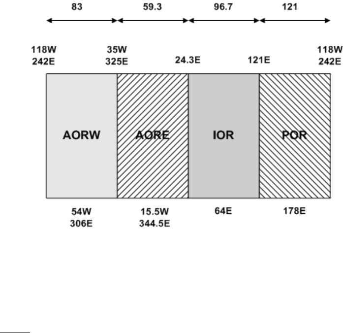
SYSTEM DESCRIPTION, INSTALLATION, AND MAINTENANCE MANUAL
eNfusion™ HSD-X and HSD-Xi High-speed Data Terminal
23-15-30 A-1
8 MAY 09
APPENDIX A: INMARSAT SATELLITE BEAM
COVERAGE
Inmarsat operates strategically placed geostationary satellites called I-3 and I-4. I-3 satellites
provide access to services such as Swift64 and Aero H/H+, and I-4 satellites provide access
to SBB services.
Each I-3 satellite is located over and named after an OR. The four satellite ORs are:
• Atlantic Ocean Region-East (AOR-E)
• Atlantic Ocean Region-West (AOR-W)
• Indian Ocean Region (IOR)
• Pacific Ocean Region (POR)
Figure A-1 represents the satellite ORs with approximate transfer coordinates for satellite
transitions.
Figure A-1 Satellite ORs
The four satellite ORs are made up of smaller, spot-beam coverage areas. The following maps
show the Inmarsat satellite spot-beam coverage for the four ORs, and a composite map of
the four regions combined.
NOTE: Figure A-2 and Figure A-3 depict Inmarsat's expectations of coverage but do not
represent a guarantee of service and should not be relied upon. The availability of
service at the edge of coverage areas fluctuates depending upon a variety of
conditions.
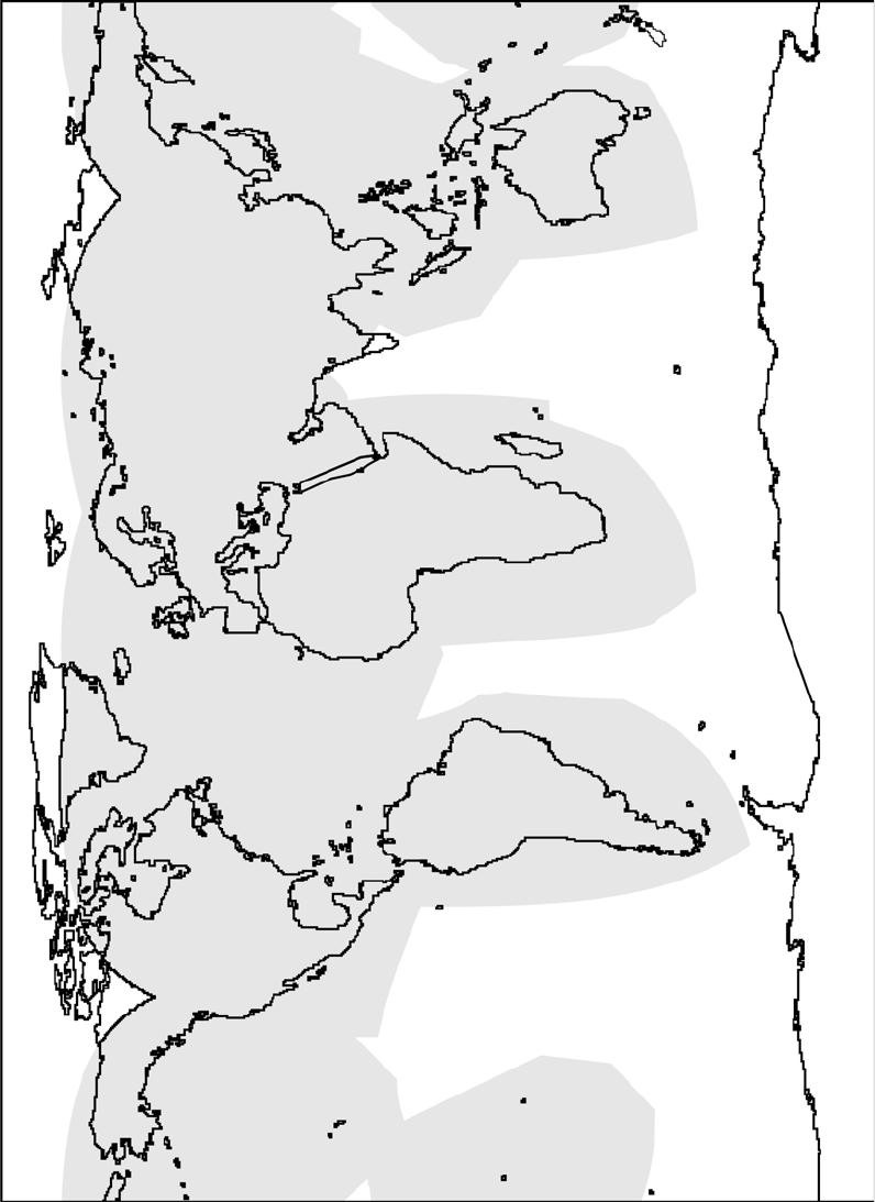
SYSTEM DESCRIPTION, INSTALLATION, AND MAINTENANCE MANUAL
eNfusion™ HSD-X and HSD-Xi High-speed Data Terminal
23-15-30 A-2
8 MAY 09
Figure A-2 Inmarsat I3 Satellite Beam Coverage—Composite Map
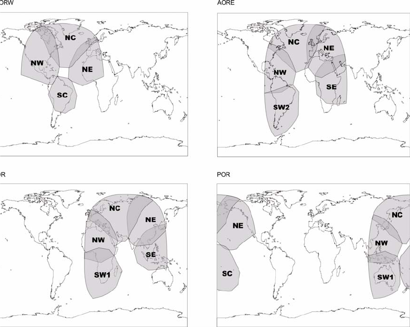
SYSTEM DESCRIPTION, INSTALLATION, AND MAINTENANCE MANUAL
eNfusion™ HSD-X and HSD-Xi High-speed Data Terminal
23-15-30 A-3
8 MAY 09
Figure A-3 Inmarsat I-3 Satellite Beam Coverage—OR Maps
At the time of publishing, three I-4 satellites provide SBB services: Americas (98W), EMEA
(25E) and Asia-Pacific (143.5E).
Figure A-4 shows the area covered by I-4 satellites.
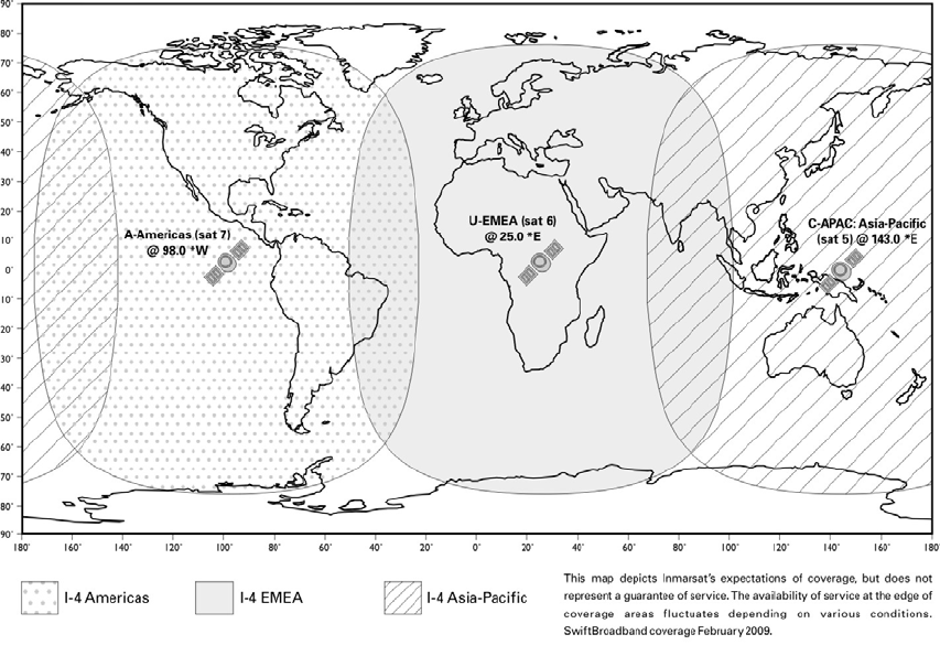
SYSTEM DESCRIPTION, INSTALLATION, AND MAINTENANCE MANUAL
eNfusion™ HSD-X and HSD-Xi High-speed Data Terminal
23-15-30 A-4
8 MAY 09
Figure A-4 I-4 Satellite Coverage Map

SYSTEM DESCRIPTION, INSTALLATION, AND MAINTENANCE MANUAL
eNfusion™ HSD-X and HSD-Xi High-speed Data Terminal
23-15-30 B-1
8 MAY 09
APPENDIX B: TROUBLESHOOTING CHECKLIST
Before performing the detailed testing and troubleshooting procedures provided in this
manual, read the following Troubleshooting Checklist. Use the Troubleshooting Checklist to
make sure that you have not missed any key steps in the HSD-X and HSD-Xi terminal setup.
1. Have you registered with a service provider to activate service?
You must register with an Inmarsat-authorized service provider to activate an account
to access the Satellite Communications network using an HSD-X and HSD-Xi
terminal. Contact Inmarsat for a list of available service providers at:
Inmarsat Customer Care
99 City Road, London, EC1Y 1AX
Tel: +44 20 7728 1777
Fax: +44 20 7728 1142
E-mail: customer_care@inmarsat.com
2. Has your account been activated?
Once registered, your HSD-X and HSD-Xi terminal is assigned terminal identification
numbers called FWD IDs. The HSD-X and HSD-Xi terminal must be strapped
accordingly. Refer to "Installation" on page 3-1 for detailed strapping and installation
instructions.
NOTE: The service registration information may take a few days to be incorporated
into the system databases at the LES level. New terminals being
commissioned are not validated by the LES until their customer database has
been updated by Inmarsat to reflect the registration and activation of your
terminal.
NOTE: To verify that the service registration information has been validated at the
LES, call 33 POUND KEY for assistance. Confirm with the LES operator that
the FWD IDs assigned to your terminal are valid and active.
3. Is the HSD-X and HSD-Xi terminal seated properly?
In cases where the HSD-X and HSD-Xi terminal is not fully seated into the ARINC
600 connector (to the rear of the Fan Tray), the user may experience intermittent
system operation. If intermittent system operation occurs:
• Check that the polarization pins are installed correctly as indicated on the
applicable Outline and Installation diagram.
• Make sure that the HSD-X and HSD-Xi terminal is fully inserted into the tray and
that the front hold-down screws are properly tightened to secure the terminal.
4. Is all cabling attached correctly and securely?
Broken connections and improper cabling are the most common causes of HSD-X
and HSD-Xi terminal malfunctions. Before proceeding with testing and
troubleshooting, complete the following checks:
• Check that all cables and wiring are routed and connected correctly and securely.
• Make sure that the terminal is installed with the correct power source.
SYSTEM DESCRIPTION, INSTALLATION, AND MAINTENANCE MANUAL
eNfusion™ HSD-X and HSD-Xi High-speed Data Terminal
23-15-30 B-2
8 MAY 09
• Verify that all external user and networking devices (for example: TAs, routers, fax,
telephones, computers) are connected and configured properly.
5. Have any changes to the system been made?
For previously installed and functional terminals, make note of any changes made to
the system since the last time the terminal functioned without problems.
• Were any new devices or systems connected to the terminal?
• Have any connecting devices or equipment been removed or replaced? If so, check
that all new or replaced connections are attached and configured correctly.
• Have you changed service providers or re-configured the system in any way?
6. Are your Primary and Secondary LES Access Codes programmed for all ORs?
The system default for LES access codes is set to 0 (zero), which must be configured
to valid LES access codes before operation. Refer to "System Operation" on page
2-1 for details.
7. Was the operational mode of the system strapped or configured correctly?
Verify that the system mode wiring straps match the installation configuration mode.

SYSTEM DESCRIPTION, INSTALLATION, AND MAINTENANCE MANUAL
eNfusion™ HSD-X and HSD-Xi High-speed Data Terminal
23-15-30 C-1
8 MAY 09
APPENDIX C: INSTALLATION PLANNING CHECKLIST
Installation Planning Steps
1. Register the terminal
Record the following information (provided by EMS SATCOM upon purchase)
Inmarsat Serial Numbers (ISN) x 4 1
2
3
4
Contact your Service Provider and provide the four 12-digit ISNs from above
IMSI Number 1
IMSI Number 2
Record the FWD IDs received (from your Service Provider or from Inmarsat) and
corresponding Inmarsat Mobile Numbers (IMN)
1 2 3 4
FWD IDs
(last 6 digits of ISN)
IMNs
ISDN speech
ISDN
(3.1 kHz audio)
ISDN 56 kbps
ISDN 64 kbps
ISDN
(4.8k audio)
MPDS
Service Provider
LES Access Codes (depend on Service Provider)
AOR-W
AOR-E
IOR
POR
2. Pin Strapping
The following strapping is required
Item Strapped pins, for example, TP1A to BP1A

SYSTEM DESCRIPTION, INSTALLATION, AND MAINTENANCE MANUAL
eNfusion™ HSD-X and HSD-Xi High-speed Data Terminal
23-15-30 C-2
8 MAY 09
Fwd ID
System mode
Data I/O
(if applicable)
SDI
3. Wiring
Antenna Multi-Control
BITE A/B
HPA Mute A/B
Power
ISDN:
Wire the ISDN line. Channels 1 and 2 operate over ISDN 1. ISDN-1
Ethernet:
Wire the Ethernet port for SBB.
Ethernet-1
Inertial Navigation System (INS)
Analog Tip/Ring (POTS)
CEPT-E1, Future PBX applications (optional)
4. Configuration
Program the Land Earth Station (LES) Access Codes
Configure the CNX Cabin Gateway if required
Installation Planning Steps

SYSTEM DESCRIPTION, INSTALLATION, AND MAINTENANCE MANUAL
eNfusion™ HSD-X and HSD-Xi High-speed Data Terminal
23-15-30 D-1
8 MAY 09
APPENDIX D: INSTALLATION CHECKLIST
Aircraft Identification: Network Mode HSD
Terminal Model No.:
HSD Terminal Install.
Mode: Network Mode HSD
Terminal Serial No.:
Name Signature Date
Checks completed by:
Approved/Witnessed by:
Section Parameter Item N/A 9Value
Installation / Mechanical
Physical Service/maintenance access
Environmental considerations—see
"HSD-Xi Terminal Environmental
Characteristics" on page 1-5
Fan Tray Plug configuration—see
Chassis bonding—see
Fan rotation—unobstructed
ARINC 600 Con. Polarized pins
Installation / Electrical
Power
Connections + 28 V dc polarity
115 V ac polarity
Chassis grounding
Voltage Levels + 28 V dc level
115 V ac level
IRS Input IRS wiring
IRS format

SYSTEM DESCRIPTION, INSTALLATION, AND MAINTENANCE MANUAL
eNfusion™ HSD-X and HSD-Xi High-speed Data Terminal
23-15-30 D-2
8 MAY 09
Move the aircraft in a circle and check the signal and C/No.
Config. Strap
Pins SDI
System configuration
Forward address
WOW (optional)
Ethernet Wired to RJ45 distribution points
ISDN Wired to RJ45 distribution points
Remotes Manual reset switch operation
Maintenance port (DB9 access)
Power and Fault indicators
RF Coaxial Rx i/p cable loss
Tx o/p cable loss
Antenna Antenna manufacturer and type
Wired as per manufacturer
Configuration LES Access codes
Stand-Alone Mode
FWD ID
Test
System
Power-Up Visual LED indications
Power-up computer display
Test On-Air
System Logon Reset message observed
Logon verified
Test
Optional Checks Ground segment
Flight segment
Section Parameter Item N/A 9Value

Operational Test
Heading
(Deg) Antenna
Selected Antenna
Azimuth
HSD-Xi terminal
CH 1
Signal
15
30
45
60
75
90
105
120
135
150
165
180
195
210
225
240
255
270
285
300
315
330
345
360
SYSTEM DESCRIPTION, INSTALLATION, AND MAINTENANCE MANUAL
eNfusion™ HSD-X and HSD-Xi High-speed Data Terminal
23-15-30 D-3
8 MAY 09
SYSTEM DESCRIPTION, INSTALLATION, AND MAINTENANCE MANUAL
eNfusion™ HSD-X and HSD-Xi High-speed Data Terminal
23-15-30 D-4
8 MAY 09
Blank Page

SYSTEM DESCRIPTION, INSTALLATION, AND MAINTENANCE MANUAL
eNfusion™ HSD-X and HSD-Xi High-speed Data Terminal
23-15-30 E-1
8 MAY 09
APPENDIX E: INMARSAT CAUSE CODES
Table E-1 defines the maintenance port menu fault codes of the HSD-X and HSD-Xi
terminal.
Table E-1 Inmarsat Cause Code Definitions
Inmarsat Cause Code Code Definition
1001 Call cleared by MES terminal (normal termination of call)
1011 Call failed, MES terminal busy
1012 Call cleared, MES terminal busy
1021 Call failed, MES time-out (no answer)
1081 Call failed, MES terminal not installed
1091 Call failed, MES terminal out-of-service
1092 Call cleared, MES terminal out-of-service
1141 MES preempted clear by higher priority call
1142 MES preempted fixed call by higher priority call
1143 Offered call cleared, pre-empted at MES
1144 Call cleared, MES initiated preemption
1145 Attempted call cleared, pre-empted at MES
1146 Attempted call abandoned by MES terminal
1202 Handover, MES ready
1281 Call failed, MES cannot accept
1291 Call failed, MES cannot accept at present
1351 Call cleared, insufficient free memory
1361 Call cleared by MES cable unwrap
1362 Call cleared, long interruption in reception at MES
1363 MES secondary clear due to repoint OR
1391 Call cleared, traveled distance exceeds 700km
1392 Call cleared, spot beam transition (call terminated because
aircraft left spot beam)
1393 Call cleared, cooperative mode
1451 Call failed, terrestrial circuits congested
1452 Call failed, LES congested (no channel and no circuit)
1502 Handover, LES Ready, normal clear
1551 Call failed, LES congested (no channel)
1581 Call failed, service not provided at this LES
1591 Call failed, service temporarily not available at this LES
1592 Call cleared, credit card type not supported
1651 Call failed, LES congested (no channel terminal)

SYSTEM DESCRIPTION, INSTALLATION, AND MAINTENANCE MANUAL
eNfusion™ HSD-X and HSD-Xi High-speed Data Terminal
23-15-30 E-2
8 MAY 09
1661 Call failed, long interruption in reception at LES
1662 LES long term blockage of SCPC MES
1790 Call cleared, failure credit card validation process
1791 Call cleared, failure authentication process
1811 NCS MES ID busy
1812 NCS MES ID busy IPDS
1841 Call cleared, NCS initiated preemption for incoming Pri.1 call
1842 Call cleared, NCS initiated preemption for incoming Pri.2 call
1843 Call cleared, NCS initiated preemption for incoming Pri.3 call
1844 Call cleared, NCS initiated preemption
1851 Call failed, satellite congestion NCS reject no SCPC available
1852 Call failed, satellite congestion NCS reject SCPC does not
match request
1853 Call failed, lease channel congestion
1854 Call failed, MES outside spot beam coverage area
1855 Call rejected, preemption failed, no channel available
1856 Call rejected, spot beam selection failed
1857 Handover failed, channel not available
2000 MES int reject MES RQ invalid CNO
2001 MES int reject MES RQ failed qualification
2010 MES int reject MES RP invalid CNO
2011 MES int reject MES RP failed qualification
2012 MES int reject MES RP operation timeout
2020 MES int reject NCSA missing
2021 MES int reject NCSA invalid CNO
2022 MES int reject NCSA failed qualification
2023 Call failed, Signal lost on NCSA during call setup, check
antenna and try again
2024 Call failed, Missing channel assignment, try again
2025 Call failed, Signal lost on NCSC during call setup, check
antenna and try again
2030 MES int reject LES ID failed qualification
2040 MES int reject SCCS invalid CNO
2041 MES int reject SCCS not paired
2048 Call failed, invalid number dialed
2049 Call failed, terminal not ready for call, try later
2050 Call failed, Not allowed to make another mobile call yet, wait
20 seconds and try again
Table E-1 Inmarsat Cause Code Definitions (Continued)
Inmarsat Cause Code Code Definition

SYSTEM DESCRIPTION, INSTALLATION, AND MAINTENANCE MANUAL
eNfusion™ HSD-X and HSD-Xi High-speed Data Terminal
23-15-30 E-3
8 MAY 09
2051 Call failed, dialed number is barred
2052 Call failed, LES selected is barred
2053 Call failed, number dialed must be in a phonebook
2053 Call failed, terminal can only be used with a valid SIM
2055 Call failed, user not logged in
2056 Call failed, user not logged in to SIM
2057 Call failed, LES is not in SIM allowed list
2058 Call cleared, SIM removed during call
2059 Call failed, terminal is locked for outgoing calls
2060 MES int reject NCSS failed qualification
2061 MES int reject spot beam invalid
2062 Call failed, no spot beams in the ocean region, select another
OR
2063 Terminal ID is not set correctly, check with dealer
2070 Lost NCSC signal, seeking
2071 Stand-Alone Mode finished, seeking network
2080 SIM error, check SIM is inserted correctly
2090 MES int reject ORR query invalid
2091 MES int reject ORR invalid
2092 MES int reject MES RR failed qualification
2093 MES int reject MES RR invalid CNO
2094 MES int reject NCRA missing
2095 MES int reject NCRA lost lock
2100 MES int reject illegal call type
2101 MES Int reject illegal peripheral
2102 Call request failed, call already in progress
2103 Call failed, star code is badly formatted
2104 Call failed, cannot accept two address book star codes
2105 Call failed, address book entry not found
2106 Call failed, star code does not exist
2120 MES int reject no transmit power available
2200 Battery flat for terminal operation
2201 Call cleared, used all allocated time for call type
2300 MES int reject no coop response
2301 MES int reject no power
2302 MES int reject no location report
2400 MES int reject no ORA SU found
Table E-1 Inmarsat Cause Code Definitions (Continued)
Inmarsat Cause Code Code Definition

SYSTEM DESCRIPTION, INSTALLATION, AND MAINTENANCE MANUAL
eNfusion™ HSD-X and HSD-Xi High-speed Data Terminal
23-15-30 E-4
8 MAY 09
8000 ACSE Recycling
8001 ACSE Top Of Find BB
8002 ACSE Top Of Process BB
8010 ACSE Finding Primary NCS Long
8011 ACSE Finding Secondary NCS Short
8012 ACSE Finding Primary Standalone Short
8013 ACSE Finding Primary NCS Short
8014 ACSE Finding Primary Standalone Long
8018 ACSE Finding Secondary Standalone Short
8019 ACSE Finding Secondary Standalone Long
8020 ACSE Found Primary NCS
8021 ACSE Found Secondary NCS
8022 ACSE Found Primary Standalone
8023 ACSE Found Secondary Standalone
8024 ACSE found primary NGNCS
8025 ACSE found secondary NGNCS
8030 ACSE NSR Invalid
8040 ACSE Inert
8041 ACSE ODU Status
8080 ACSE NSR Valid
8081 ACSE NSR Valid LES A
8100 ACSE Booting
8110 ACSE Booted
8120 ACSE FIDR ID Invalid
8200 ACSE Spot Beam Selection
8201 ACSE Next Spot Beam
8202 ACSE Successful Spot Beam Selection
8203 ACSE Failed To Find Spot Beam
8204 ACSE Spot Beam Selective Clear
8210 ACSE Spot Beam Reject Mobile Call No ID
8211 ACSE Spot Beam Reject Mobile Call No TDM
8300 ACSE ORR
8301 ACSE Successful ORR
8302 ACSE Failed ORR
8303 ACSE No ORR
8304 ACSE ORR Tune NCRA
8305 ACSE ORR MES RR
Table E-1 Inmarsat Cause Code Definitions (Continued)
Inmarsat Cause Code Code Definition

SYSTEM DESCRIPTION, INSTALLATION, AND MAINTENANCE MANUAL
eNfusion™ HSD-X and HSD-Xi High-speed Data Terminal
23-15-30 E-5
8 MAY 09
8306 ACSE failed retry ORR
8310 ACSE ORR Query Begin
8311 ACSE ORR Query Burst
8312 ACSE ORR Query Successful
8313 ACSE ORR Query Failed
8400 ACSE Fixed Begin
8401 ACSE Fixed MESRP
8402 ACSE Fixed Call Type Set
8410 ACSE Fixed Tune NCSA
8411 ACSE Fixed Channel Assignment
8420 ACSE Fixed Clearing Call
8421 ACSE Fixed Selective Clear
8480 ACSE Fixed SCPC Begin
8481 ACSE Fixed SCPC Transmitting
8482 ACSE Fixed Authentication Begin
8483 ACSE Fixed Authentication End
8484 ACSE Fixed Power Control
8485 ACSE Fixed MES Connect
8486 ACSE Fixed Ringing Begin
8500 ACSE Mobile Begin
8501 ACSE Mobile MES RQ1
8502 ACSE Mobile MES RQ2
8503 ACSE Mobile Call Type Set
8510 ACSE Mobile Tune NCSA
8511 ACSE Mobile Channel Assignment
8520 ACSE Mobile Clearing Call
8521 ACSE Mobile Selective Clear
8580 ACSE Mobile SCPC Begin
8581 ACSE Mobile SCPC Transmitting
8582 ACSE Mobile Authentication Begin
8583 ACSE Mobile Authentication End
8584 ACSE Mobile Power Control
8585 ACSE Mobile LES Connect
8586 ACSE Mobile Ringing Begin
8600 MPDS SCPC Mode Selected
8800 ACSE cable call begin
8801 ACSE cable call successful
Table E-1 Inmarsat Cause Code Definitions (Continued)
Inmarsat Cause Code Code Definition

SYSTEM DESCRIPTION, INSTALLATION, AND MAINTENANCE MANUAL
eNfusion™ HSD-X and HSD-Xi High-speed Data Terminal
23-15-30 E-6
8 MAY 09
8900 ACSE Logoff Begin
8901 ACSE Successful Logoff
8902 ACSE No ORR Logoff
9000 ACSE accepts call
9003 ACSE accepted
9004 ACSE rejected
9020 ACSE call waiting
9021 ACSE idle selective clear
9022 ACSE TDM not found
9080 ACSE rejected fixed call due to invalid NSR
9081 ACSE In MRSi
9082 ACSE sounder turned on
9083 ACSE sounder turned off
9084 ACSE in lock
9085 ACSE out of lock
9086 ACSE ext sounder turned on
9087 ACSE ext sounder turned off
9088 ACSE timer about to expire
9090 ACSE Smartcard activated
9091 ACSE Smartcard removed
9092 ACSE Smartcard error
9100 Peripheral on hook
9101 Peripheral off hook
9102 Peripheral connected
9103 Peripheral ringing
9104 Peripheral ready
9105 Peripheral hanging up
9106 Peripheral hang up
9107 Peripheral not responding
9108 Peripheral dialing
9109 Peripheral abort dialing
9120 Peripheral DTMF accepted
9121 Peripheral DTMF rejected
9122 Peripheral invalid request
9123 Peripheral valid request
9124 Peripheral bonding auto
9125 Peripheral bonding slave
Table E-1 Inmarsat Cause Code Definitions (Continued)
Inmarsat Cause Code Code Definition

SYSTEM DESCRIPTION, INSTALLATION, AND MAINTENANCE MANUAL
eNfusion™ HSD-X and HSD-Xi High-speed Data Terminal
23-15-30 E-7
8 MAY 09
9126 Peripheral bonding none
9130 Peripheral STU enabled
9131 Peripheral STU disabled
9200 MSG T_AM received
9201 MSG A_AM received
9202 MSG T_HA received
9203 MMI normal
9204 MMI inert
9205 MMI programming
9206 MMI reboot
9207 MMI powerdown
9208 MMI accepted
9209 MMI rejected
400000 CT SP bad
400000 No call pending
400001 CT SP good
400002 CT SP full
400003 CT SP access denied
400080 CT SP find
400081 CT SP enumerate
400082 CT SP no entries
400090 CT SP delete
400100 CT SP spot beam selection
400105 CT SP MPDS
400110 CT SP ocean region registration
400111 CT SP ORR query
400112 CT SP log off
400120 CT SP cable call
400200 CT SP go idle
400201 CT SP go idle due to configuration
400202 CT SP selective clear
400208 CT SP go idle clear spot beam
400209 CT SP go idle clear NSR
400210 CT SP go inert
400211 CT SP go inert Smartcard
400212 CT SP go inert DDS poll
400900 CT SP ODU status
Table E-1 Inmarsat Cause Code Definitions (Continued)
Inmarsat Cause Code Code Definition

SYSTEM DESCRIPTION, INSTALLATION, AND MAINTENANCE MANUAL
eNfusion™ HSD-X and HSD-Xi High-speed Data Terminal
23-15-30 E-8
8 MAY 09
400901 CT SP ODU status no alarms
400902 CT SP ODU status DDS
400910 CT SP prod test
400911 CT SP prod test ODU
401000 CT SP clear spot beam
800103 Mobile AMBE
800124 Mobile aero 64k speech
800404 Mobile data
800504 Mobile facsimile
800606 Mobile 64k UDI
800607 Mobile 56k UDI
800610 Mobile 64k audio 3k1
800622 Mobile aero 64k UDI
800623 Mobile aero 56k UDI
800625 Mobile aero 64k audio 3k1
11A0 Call cleared, credit card not accepted
11D1 Call failed, Request data invalid
11D2 Call failed, insufficient digits in service address
11D3 Call failed, invalid service address
11D4 Call cleared, credit card data information invalid
11D5 Call cleared, invalid country code
11D6 Call cleared, PID information is not consistent
11D7 Call rejected, invalid service for Pri.1 or 2 call
11D8 Call cleared, dialed number not 2 or 3 digits for Pr.1 or 2 call
11E0 Call cleared, invalid credit card PIN at this LES
11E1 Call cleared, too many invalid credit card call attempts
12B1 Call cleared by MES for unspecified reason, for example:
• GPS conflict
• Insufficient HPA power available to make call
• HPA over current
12C2 Call cleared, no credit card valid message received
12C3 Call failed, MES time-out (no terrestrial answer)
12C4 Call cleared, authentication query not received (usually caused
by call setup failure)
12C5 Call cleared, MES missing sup service SU
12C6 Call cleared, MES missing sup service 2SU
Table E-1 Inmarsat Cause Code Definitions (Continued)
Inmarsat Cause Code Code Definition

SYSTEM DESCRIPTION, INSTALLATION, AND MAINTENANCE MANUAL
eNfusion™ HSD-X and HSD-Xi High-speed Data Terminal
23-15-30 E-9
8 MAY 09
12C7 Call cleared, MES missing SCPC channel release SU sup
service
12C8 Handover failed, LES not detected
12D1 Call failed, Spot-beam data invalid
12D2 Call failed, invalid scrambling vector
15A1 Call failed, MES not authorized at this LES
15A2 Call failed, service not authorized at this LES
15A3 Call cleared, credit card not authorized
15A4 Call cleared, authentication reply invalid
15A5 Call failed, PID not authorized for any service
15A6 Call failed, PID not authorized for requested service
15B1 Call cleared by LES for unspecified reason
15C1 Call failed, LES time-out (no assignment)
15C2 Call failed, LES time-out (no service address)
15C3 Call failed, LES time-out (no scrambling vector)
15C4 Call failed, no service address and no scrambling vector
15C5 Call cleared, incomplete credit card data information
15C7 Call failed, LES time-out (no MES Connect)
15C9 Call cleared, no authentication reply
15CA Call cleared, notification ack not received
15CB Call cleared, invalid sequence number in notification ack
15CC Handover failed, no response to request
15CD Handover failed, MES not ready
15D1 Call failed, LES time-out (invalid assignment)
15D2 LES MES already busy
15E1 Call cleared but MES still transmitting (FAULT)
16C2 LES missing MES SCPC
16C3 Handover failed, MES not detected
18A1 NCS MES ID not found
18A2 Call failed, MES not authorized
18A3 Call failed, LES not authorized
18B1 Call failed by NCS for unspecified reason
18B2 Call rejected, invalid service requested
18C1 NCS MES burst missing
18C3 NCS MES busy preemption failed
18D1 Call failed, invalid call request
18E1 NCS MES busy already
Table E-1 Inmarsat Cause Code Definitions (Continued)
Inmarsat Cause Code Code Definition

SYSTEM DESCRIPTION, INSTALLATION, AND MAINTENANCE MANUAL
eNfusion™ HSD-X and HSD-Xi High-speed Data Terminal
23-15-30 E-10
8 MAY 09
18E2 NCS MES busy already MPDS
1F01 Call cleared by terrestrial circuit (normal call termination from
ground source)
1F11 Call failed, terrestrial party busy
1F21 Call failed, LES time-out (no answer)
1F61 Call failed, terrestrial circuit failure (call attempted during ORR)
1F62 Call failed, early clear by terrestrial circuit
2F00 LES int reject lack of MES RESP response
2F01 LES int reject lack of MES ARN response
2F02 LES int reject incorrect SVECSCPC
4000A0 CT SP any
4000F0 CT Terminal ID
4000F1 CT Options
4000F2 CT config names
80010F Mobile 64k speech
8D0FFF Mobile Mini-M
8E0FFF Mobile HSD
8F0FFF Mobile
90A0 EXPPORT bonding started
90A1 EXPPORT bonding ended
90A2 EXPPORT remote panel present
90A3 EXPPORT remote panel removed
90B0 ACSE MPDS mode selected
90B1 ACSE SCPC mode selected
90C0 ACSE transmit on
90C1 ACSE transmit off
90D0 ACSE spot beam handover started
90D1 ACSE spot beam termination timer started
90F0 Event log wiped
B000 Mod error, general
B001 Mod error, tune failed
B002 Mod error, mode failed
B003 Mod error, mmr failed
B004 Mod error, not responding
B010 MOD Invalid Mode
B011 MOD Command Invalid
B020 Mod error, su underflow
Table E-1 Inmarsat Cause Code Definitions (Continued)
Inmarsat Cause Code Code Definition

SYSTEM DESCRIPTION, INSTALLATION, AND MAINTENANCE MANUAL
eNfusion™ HSD-X and HSD-Xi High-speed Data Terminal
23-15-30 E-11
8 MAY 09
B021 MOD Su overflow
B022 MOD Su not transmitted
B024 MOD invalid frame no
B025 MOD invalid slot no
B028 MOD cannot Tx Su while tuning
B030 MOD channel out of range
B032 MOD cannot tune while Tx
B033 MOD tuning in progress
B040 MOD error watchdog
B100 DEMOD error, general
B101 DEMOD error, tune failed
B102 DEMOD error, mode failed
B110 DEMOD invalid mode
B130 DEMOD channel out of range
B133 DEMOD tuning in progress
B200 Generic modem error
B201 RF error RX VHF
B202 RF error RX Lband
B204 RF error RX VHF
B208 RF error TX Lband
B210 RF error RF error
B220 RF error Ref error
B27F Mod watchdog tripped
B280 Generic voice codec errors
B281 TMS spurious interrupt
B300 Outdoor terminal failure, check connections to ODU
B301 ODU error cannot set cable attenuator
B310 ODU error power response missing
B311 ODU error tune response missing
B312 ODU error HPA control response missing
B313 ODU error HPA status response missing
B314 ODU error alarm response missing
B315 ODU error burst timer response missing
B316 ODU error HPA backoff response missing
B320 ODU error alarm heat
B321 ODU error alarm burst
B322 ODU error alarm power
Table E-1 Inmarsat Cause Code Definitions (Continued)
Inmarsat Cause Code Code Definition

SYSTEM DESCRIPTION, INSTALLATION, AND MAINTENANCE MANUAL
eNfusion™ HSD-X and HSD-Xi High-speed Data Terminal
23-15-30 E-12
8 MAY 09
B323 ODU error alarm over voltage
B324 ODU error alarm reverse power
B328 ODU failed due to tx power check
B329 ODU error alarm timeout
B330 ODU error alarm timeout no trip
B400 Internal temperature of terminal too high, turn off for 10 minutes
B401 Internal temperature sensor failed
B410 Mod error, handshake failure, power down/up and try again
B500 Battery charging communication failure
B501 Power supply error
B580 Battery is over temperature, charging disabled
B581 Battery temperature is now ok, charging enabled
C00103 Fixed AMBE
C0010F Fixed 64k speech
C00124 Fixed aero 64k speech
C00404 Fixed data
C00504 Fixed facsimile
C00606 Fixed 64k UDI
C00607 Fixed 56k UDI
C00610 Fixed 64k audio 3k1
C00622 Fixed aero 64k UDI
C00623 Fixed aero 56k UDI
C00625 Fixed aero 64k audio 3k1
CD0FFF Fixed Mini-M
CE0FFF Fixed HSD
CF0FFF Fixed
FFFD ACSE end marker (MPDS)
FFFE Status undefined (MPDS)
FFFF Status OK (MPDS)
Table E-1 Inmarsat Cause Code Definitions (Continued)
Inmarsat Cause Code Code Definition
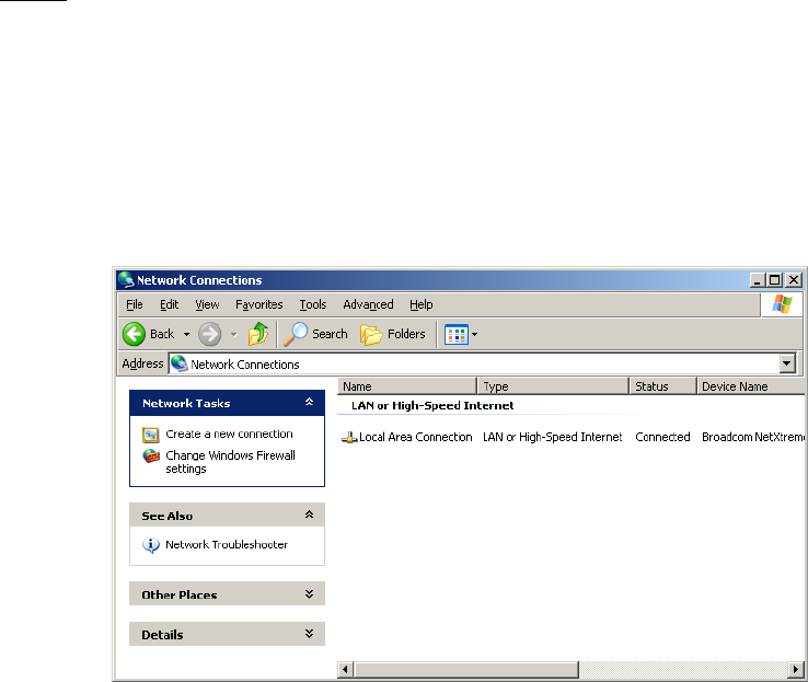
SYSTEM DESCRIPTION, INSTALLATION, AND MAINTENANCE MANUAL
eNfusion™ HSD-X and HSD-Xi High-speed Data Terminal
23-15-30 F-1
8 MAY 09
APPENDIX F: SETTING UP SBB
This appendix describes how to set up a single client on a packet-switched SBB connection.
1. Requirements
To configure and use a background standard IP connection, you must connect a computer to
the Ethernet port of the HSD-X and HSD-Xi terminal. If you are connecting a computer or
router to the Ethernet port of the HSD-Xi terminal, use a RJ-45 cross-over cable. If you are
connecting a hub or switch, use a RJ-45 straight-through cable.
2. Configuring a Standard IP Primary PDP Context
The connection that you configure in this section defines the primary PDP context. You can
configure any type of connection for the primary PDP context, but a standard IP connection,
as illustrated in this procedure, is the most common and useful. To create other connections,
see "Creating Connections for Other Services" on page F-7.
NOTE: This connection must be active before you can establish other connections with other
PDP contexts.
(a) To create a PPPoE connection
1. Click the Start button, point to Settings, and then click Control Panel.
The Control Panel appears.
2. Double-click Network Connections.
The Network Connections window appears, as shown in Figure F-1.
Figure F-1 Network Connections Window
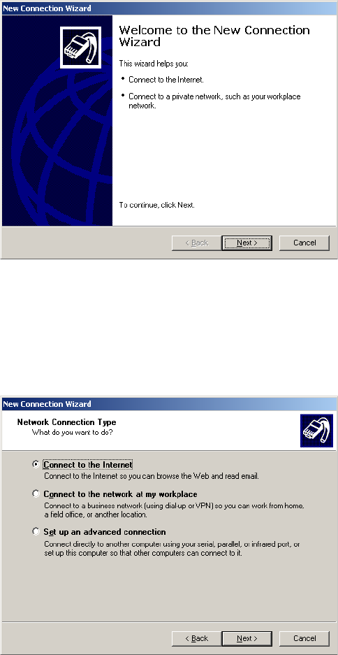
SYSTEM DESCRIPTION, INSTALLATION, AND MAINTENANCE MANUAL
eNfusion™ HSD-X and HSD-Xi High-speed Data Terminal
23-15-30 F-2
8 MAY 09
3. Click Create a new connection.
The New Connection Wizard appears, as shown in Figure F-2.
Figure F-2 New Connection Wizard
4. Click Next.
The Network Connection Type page appears, as shown in Figure F-3.
Figure F-3 Network Connection Type Page
5. Click Connect to the Internet, and then click Next.
The Getting Ready page appears, as shown in Figure F-4.
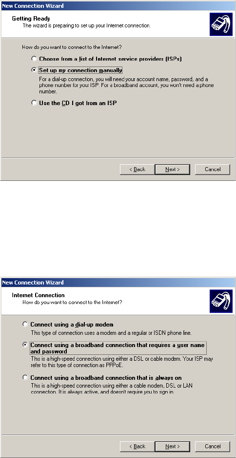
SYSTEM DESCRIPTION, INSTALLATION, AND MAINTENANCE MANUAL
eNfusion™ HSD-X and HSD-Xi High-speed Data Terminal
23-15-30 F-3
8 MAY 09
Figure F-4 Getting Ready Page
6. Click Set up my connection manually, and then click Next.
The Internet Connection page appears, as shown in Figure F-5.
Figure F-5 Internet Connection Page
7. Click Connect using a broadband connection that requires a user name
and password, and then click Next.
The Connection Name page appears, as shown in Figure F-6.
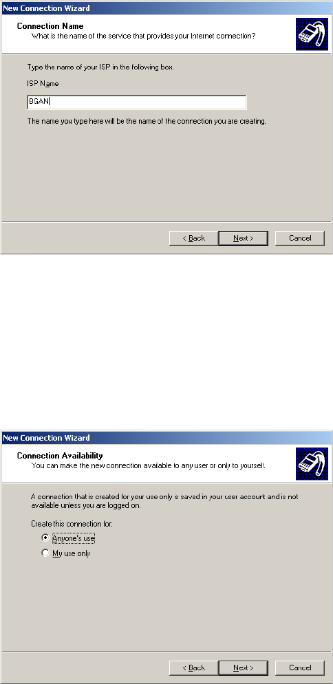
SYSTEM DESCRIPTION, INSTALLATION, AND MAINTENANCE MANUAL
eNfusion™ HSD-X and HSD-Xi High-speed Data Terminal
23-15-30 F-4
8 MAY 09
Figure F-6 Connection Name Page
8. In the ISP Name box, type BGAN, and then click Next.
The name you type is the name that appears in the list of connections
available on your computer.
The Connection Availability page appears, as shown in Figure F-7.
Figure F-7 Connection Availability Page
9. Click Anyone's use or My use only, and then click Next.
The Internet Account Information page appears, as shown in Figure F-8.
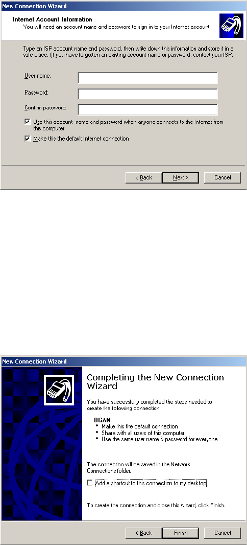
SYSTEM DESCRIPTION, INSTALLATION, AND MAINTENANCE MANUAL
eNfusion™ HSD-X and HSD-Xi High-speed Data Terminal
23-15-30 F-5
8 MAY 09
Figure F-8 Internet Account Information Page
10. In the User name box, type a user name that you will remember.
11. In the Password box, type a password that you will remember.
12. In the Confirm password box, retype your password.
13. Click Next.
The Completing the New Connection Wizard page appears, as shown in
Figure F-9.
Figure F-9 Completing the New Connection Wizard Page
14. To complete the connection setup, click Finish.
The Connect dialog box appears, as shown in Figure F-10.
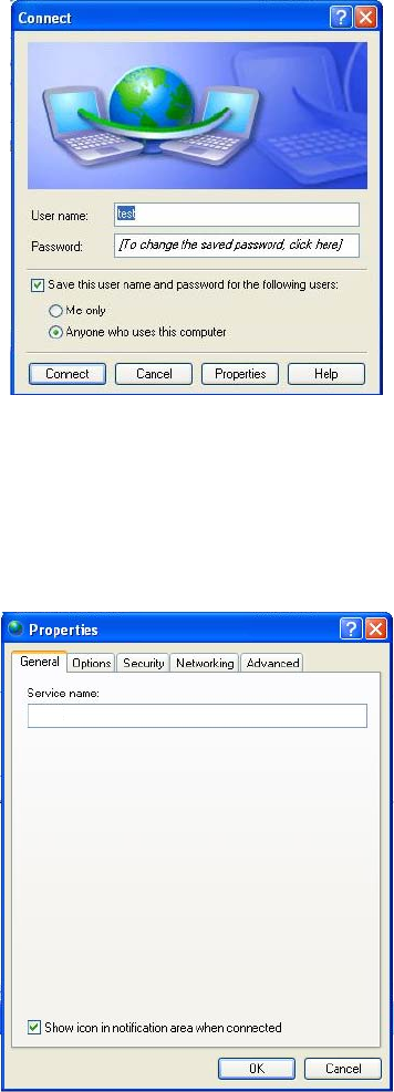
SYSTEM DESCRIPTION, INSTALLATION, AND MAINTENANCE MANUAL
eNfusion™ HSD-X and HSD-Xi High-speed Data Terminal
23-15-30 F-6
8 MAY 09
Figure F-10 Connect Dialog Box
15. Click Properties.
The Properties dialog box appears, as shown in Figure F-11.
Figure F-11 Properties Dialog Box
16. In the Service Name box, type the service string
SBB:BACKGROUND@USER=username@PASS=password@APN=my
.apn.com.
• SBB:BACKGROUND for Background IP service

SYSTEM DESCRIPTION, INSTALLATION, AND MAINTENANCE MANUAL
eNfusion™ HSD-X and HSD-Xi High-speed Data Terminal
23-15-30 F-7
8 MAY 09
•SBB:BACKGROUND@APN=my.apn.com for Background IP
service that uses specific access point name
•SBB:BACKGROUND@USER=username@PASS=password for
Background IP service that uses a specific username and password.
Replace “username”, “password”, and “my.apn.com” with your username,
password, and APN IP address.
This defines the primary PDP context as a background SBB connection.
NOTE: Some routers do not support dial strings. To access a service,
configure the default service name in the data I/O card, and the
HSD-X and HSD-Xi terminal will add the service name to the call.
3. Creating Connections for Other Services
You can create a connection for every service you use on your computer, such as 32 kbps
and 64 kbps services.
To create a connection:
• Follow the procedure above for Configuring a Standard IP Primary PDP Context, and, in
step 16, type one of the following service names:
•SBB:STREAM32K for 32 K streaming service
•SBB:STREAM64K for 64 K streaming service
•SBB:STREAM128K for 128 K streaming service
SYSTEM DESCRIPTION, INSTALLATION, AND MAINTENANCE MANUAL
eNfusion™ HSD-X and HSD-Xi High-speed Data Terminal
23-15-30 F-8
8 MAY 09
Blank Page