User Manual
0
ARNIX
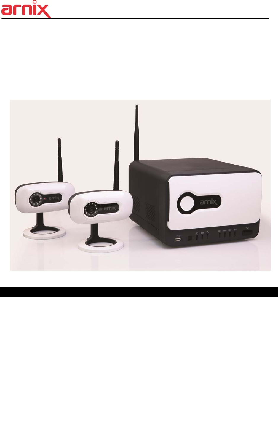
Wired/Wireless All-In-One Surveillance System
User Manual
Thank you for purchasing our wired/wireless all-in-one surveillance system.
Before start using this product, please ensure that you read and understand the
User Manual.
Please store the User Manual at an easily accessible location.
Before connecting and installing monitors, alarms and computers, please refer to
the appropriate instruction manual for proper operation.
1
SAFETY PRECAUTIONS
CAUTION:
TO REDUCE THE RISK OF ELECTRIC SHOCK, DO NOT REMOVE COVER (OR BACK).
NO USER SERVICEABLE PARTS INSIDE. REFER SERVICING TO QUALIFIED
SERVICE PERSONNEL.
The lightning flash with arrowhead symbol, within an equilateral
triangle, is intended to alert the user to the presence of un insulated
“dangerous voltage” within the product’s enclosure that may be of
sufficient magnitude to constitute a risk of electric shock to persons.
The exclamation point within an equilateral triangle is intended t
o alert the user to the presence of important operating and mai
ntenance (servicing) instructions in the literature accompanying t
he appliance.
WARNING:
TO PREVENT FIRE OR ELECTRIC SHOCK HAZARD,
DO NOT EXPOSE THIS APPLIANCE TO RAIN OR MOISTURE.

2
Contents
Disclaimer .............................................................................................................................................. 5
Warning .................................................................................................................................................. 5
Caution ................................................................................................................................................... 6
Preventing Malfunction ......................................................................................................................... 7
Regulatory .............................................................................................................................................. 7
Package Contents.................................................................................................................................. 9
I. ARNIX ALL-IN-ONE PACKAGE ........................................................................................................ 10
1. IP Camera .................................................................................................................................. 10
2. NVR .............................................................................................................................................11
3. Remote Controller .................................................................................................................... 12
4. Mouse Control .......................................................................................................................... 14
5. Virtual Keyboard for Mouse Control ...................................................................................... 14
II. INSTALLATION & CONNECTIONS ................................................................................................. 15
1. Camera, Monitor, Audio, Alarm sensor and Power cord ...................................................... 15
III. QUICK START PAGE ....................................................... 오류! 책갈피가 정의되어 있지 않습니다.
IV. LIVE VIEWING ................................................................................................................................. 21
1. Display Overview ...................................................................................................................... 21
2. Multi-screen Display and Sequencing ................................................................................... 23
2.1. Screen Display. ....................................................................................................... 23
2.2. Multi-screen Display and Switching to Sequence Display. ................................ 23
3. Quick button for multi screen Display. .................................................................................. 23
3.1. Quick multi split mode change .............................................................................. 24
3.2. Repositioning .......................................................................................................... 24
4. Zooming .................................................................................................................................... 24
V. OPERATION ..................................................................................................................................... 26
1. LOG IN/OUT. .............................................................................................................................. 26
2. NAVIGATION THE MENU ......................................................................................................... 27
VI. SETUP ............................................................................................................................................. 28
1. DISPLAY .................................................................................................................................... 28
1.1. GENERAL ................................................................................................................ 28
1.2. SWITCH Setup (Monitor Configure) ...................................................................... 29
1.3. EVENT ...................................................................................................................... 30
2. CAMERA .................................................................................................................................... 31
2.1. CAMERA .................................................................................................................. 31
2.2. Set up IP camera MANUAL CONNECTION ........................................................... 31

3
2.3. DEVICE ..................................................................................................................... 33
2.4. Live ........................................................................................................................... 34
3. RECORD .................................................................................................................................... 34
3.1. Record General ....................................................................................................... 34
3.2. Continuous / Normal Recording ............................................................................ 35
3.3. Event Recording ..................................................................................................... 37
3.4 Continuous + Event (Motion/Alarm) Recording .................................................... 39
4. SCHEDULE ................................................................................................................................ 40
4.1. CHART Setup .......................................................................................................... 40
4.2. Holiday Setup .......................................................................................................... 42
5. DISK ........................................................................................................................................... 43
5.1. DISK Manager .......................................................................................................... 43
5.2. Recording DISK ....................................................................................................... 45
5.3. S.M.A.R.T STATUS .................................................................................................. 46
6. NETWORK ................................................................................................................................. 47
6.1. LAN Port & IPCAM Port .......................................................................................... 47
6.2. GENERAL ................................................................................................................ 48
6.3. EMAIL ....................................................................................................................... 57
6.4. SMTP ........................................................................................................................ 58
6.5. DDNS (Dynamic DNS) ............................................................................................. 59
6.6 Router & Port Forwarding ....................................................................................... 61
7. DEVICE ...................................................................................................................................... 63
7.1. GENERAL ................................................................................................................ 63
7.2. I/O Terminal .............................................................................................................. 64
7.3. PTZ EVENT (BHA-WC100 Model does not support this feature) ....................... 66
8. SYSTEM ..................................................................................................................................... 66
8.1. GENERAL ................................................................................................................ 66
8.2. TIME .......................................................................................................................... 67
8.3. ACCOUNT ................................................................................................................ 69
8.4. UPDATE .................................................................................................................... 70
8.5. INFO .......................................................................................................................... 71
VII. PLAYBACK /SEARCH ................................................................................................................... 72
1. Playback .................................................................................................................................... 72
2. Time Search .............................................................................................................................. 73
2.1 Multi Channel Playback ........................................................................................ 73
2.2 Preview Search (Single Channel Playback) ....................................................... 73
2.3 Event Record Search ............................................................................................ 74

4
2.4 Event Source Search ............................................................................................ 75
2.5 Motion Area Search (Single Channel Playback) ................................................ 76
3. Go to Search ............................................................................................................................. 77
4. Log List Search ........................................................................................................................ 78
VIII. BACKUP ........................................................................................................................................ 80
1. Manual Back Up ........................................................................................................................ 80
1.1 External DVD- R/W ................................................................................................ 80
1.2 External USB HDD/ Memory Stick .......................................................................... 82
1.3 Back up Range Setup .............................................................................................. 82
2. Auto Back Up (FTP) .................................................................................................................. 83
3. Log List Back Up ...................................................................................................................... 84
IX. WIRELESS ...................................................................................................................................... 85
X. CLIENT SOFTWARE ........................................................................................................................ 88
XI. SPECIFICATION .............................................................................................................................. 89

5
Disclaimer
The information in this manual is believed to be accurate and reliable as of the date of
publication. The information contained herein is subject to change without notice. Revisions
or New editions to this publication may be issued to incorporate such change
We make no warranties for damages resulting from corrupted or lost data due to a mistaken
operation or malfunction of the Network Video Recorder, the software, the hard drives,
personal computers, peripheral devices, or unapproved/unsupported devices.
Warning
Do not cover the ventilation opening or slots on the outer casing. To prevent the appliance
from overheating, provide at least two inches of air space around the vent and the slots.
Do not drop metallic parts through slots. This could permanently damage the Digital Video
Recorder. Immediately turn the NVR’s power off or unplug the power cord from the power
outlet. Contact a qualified service personnel authorized by your equipment distributor
Do not attempt to disassemble or alter any part of the equipment that is not expressly
described in this guide. Disassembly or alteration may result in high voltage electrical shock.
Qualified service personnel authorized by your equipment distributor should conduct internal
inspections, alterations and repairs.
Stop operating the equipment immediately if it emits smoke or noxious fumes. Failure to do
so may result in fire or electrical shock. Immediately turn the NVR’s power off, remove the
power cable from the power outlet. Confirm that smoke and fume emissions have ceased.
Please consult your NVR distributor.
Stop operating the equipment if a heavy object is dropped or the casing is damaged. Do not
strike or shake. Failure to do so may result in fire or electrical shock. Immediately turn the
NVR’s power off or unplug the power cord from the power outlet. Please consult your NVR
distributor.
Do not allow the equipment come into contact with, or become immersed in, water or other
liquids. Do not allow liquids to OK the interior. The NVR has not been waterproofed. If
the exterior comes into contact with liquids or salt air, wipe it dry with a soft, absorbent cloth.
In the event that the water or other foreign substances OK the interior, immediately turn the
NVR’s Power off or unplug the power cord from the power outlet. Continued use of the
equipment may result in fire or electrical shock. Please consult your NVR distributor.
Do not use substances containing alcohol, benzene, thinners or other flammable substances
to clean or maintain the equipment. The use of these substances may lead to fire. Use a

6
dry cloth on a regular periodic basis and wipe away the dust and dirt that collects on the
device. In dusty, humid or greasy environments, the dust that collects around the ventilation
or the slots on the outer casing over long periods of time may become saturated with
humidity and short-circuit, leading to fire.
Do not cut, damage, alter or place heavy items on the power cord. Any of these actions
may cause an electrical short circuit, which may lead to fire or electrical shock.
Do not handle the device or power cord if your hands are wet. Handling it with wet hands
may lead to electrical shock. When unplugging the cord, ensure that you hold the solid
portion of the plug. Pulling on the flexible portion of the cord may damage or expose the
wire and insulation, creating the potential for fires or electrical shocks.
Use only the recommended power accessories. Use of power sources not expressly
recommended for this equipment may lead to overheating, distortion of the equipment, fire,
electrical shock or other hazards.
Do not place the batteries near a heat source or expose them to direct flame or heat.
Neither should you immerse them in water. Such exposure may damage the batteries and
lead to the leakage of corrosive liquids, fire, electrical shock, explosion or serious injury.
Do not attempt to disassemble, alter or apply heat to the batteries. There is serious risk of
injury due to an explosion. Immediately flush with water any area of the body, including the
eyes and mouth, or clothing that comes into contact with the inner contents of the battery. If
the eyes or mouth contact these substances, immediately flush with water and seek medical
assistance from a medical professional.
Avoid dropping or subjecting the batteries to severe impacts that could damage the casings.
It could lead to leakage and injury.
Do not short-circuit the battery terminals with metallic objects, such as key holders. It could
lead to overheating, burns and other injuries.
The supplied power supply and power cord are designed for exclusive use with the Digital
Video Recorder. Do not use it with other products or batteries. There is a risk of fire and
other hazards.
Caution
Do not operate the appliance beyond its specified temperature, humidity or power source
ratings. Do not use the appliance in an extreme environment where there is high
temperature or high humidity. Use the device at temperatures within +0°C - +40°C (32°F -
104°F) and humidity below 90 %. The normal operating power source for this device is 100V-
240V AC 50/60Hz.

7
Preventing Malfunction
z Avoid Strong Magnetic Fields. Never place the NVR in close Proximity to electric motors or
other equipment generating strong electromagnetic fields. Exposures to strong magnetic
fields may cause malfunctions or corrupt image data.
z Avoid Condensation Related Problems. Moving the equipment rapidly between hot and cold
temperatures may cause condensation (water droplets) to form on its external and internal
surfaces. You can avoid this by placing the equipment in an airtight, resalable plastic bag and
letting it adjust to temperature changes slowly before removing it from the bag.
z If Condensation forms inside the Digital Video Recorder. Stop using the equipment
immediately if you detect condensation. Continued use may damage the equipment. Remove
the power cord from the power outlet and wait until the moisture evaporates completely
before resuming use.
FCC Compliance : This equipment has been tested and found to comply with the limits for a
Class A digital device, pursuant to part 15 of the FCC Rules. These limits are designed to provide
reasonable protection against harmful interference when the equipment is operated in a commercial
environment. This equipment generates, uses, and can radiate radio frequency energy and, if no
installed and used in accordance with the instruction manual, may cause harmful interference to radio
communications. Operation of this equipment in a residential area is likely to cause harmful
interference in which case the user will be required to correct the interference at his own expense.
Caution: Exposure to Radio Frequency Radiation.
To comply with FCC RF exposure compliance requirements, for mobile configurations, a separation
distance of at least 20 cm must be maintained between the antenna of this device and all persons.
This device must not be co-located or operating in conjunction with any other antenna or
transmitter
Description on Laser Specification
The optical disc drive such as DVD Super Multi (Double Layer) Drive 22X that is used in this computer
is equipped with laser. The classification label with the following sentence is affixed to the surface of
the drive.
CLASS 1 LASER PRODUCT TO IEC60825-1 LASER KLASSE 1 The drive with the above label is
certified by the manufacturer that the drive complies with the requirement for laser product on the date
Regulatory

8
of manufacturing pursuant to article 21 of Code of Federal Regulations by the United States of
America, Department of Health & Human Services, Food and Drug Administration. In other countries,
the drive is certified to comply with the requirement pursuant to IEC 60825-1 and EN 60825-1 on class
1 laser product. This computer is equipped with the optical disc drive in the following list according to
the model.
EU Conformity Statement:
2002/96/EC (WEEE Directive) : Products marked with this symbol cannot be disposed of
as unsorted municipal waste in the European Union. For proper recycling, return this
product to your local supplier upon the purchase of equivalent new equipment, or dispose of
it at designated collection points. For more information, see: www.recyclethis.info.
2006/66/EC (Battery Directive) : Products marked with this symbol cannot be disposed of
as unsorted municipal waste in the European Union. For proper recycling, return this
product to your local supplier upon the purchase of equivalent new equipment, or dispose of
it at designated collection points. For more information, see: www.recyclethis.info.
NOTE: THE MANUFACTURER IS NOT RESPONSIBLE FOR ANY RADIO OR TV INTERFERENCE
CAUSED BY UNAUTHORIZED MODIFICATIONS TO THIS EQUIPMENT. SUCH MODIFICATIONS
COULD VOID THE USER'S AUTHORITY TO OPERATE THE EQUIPMENT.
CAUTION
- Risk of Explosion if Battery is replaced by an Incorrect Type. Dispose of Used Batteries
according to the Instructions.
- The socket-outlet shall be installed near the equipment and shall be easily accessible

9
Product Outline
Product Name ARNIX Wired/Wireless All-In-One Surveillance System
Model Name BHA-WP200
User Guide Version Version 1.0
Manufacturer EMW Co., Ltd.
Address
Head Office:
80B-4L, 680-3, Gojan-Dong, Namdong-Gu, Incheon, Korea
R&D Center:
459-24, Gasan-Dong, Geumcheon-Gu, Seoul, Korea
Contact
Tel: +82-2-2107-5500(Rep.) Fax: +82-2-2107-5645
Tel: +82-2-2107-5614/5561(Sales Contact)
Email: rfsales@emw.co.kr
Website: www.emw.co.kr
Package Contents
Please check the package contents for any visible damage. If any components are damaged or
missing, do not attempt to use the unit, contact the supplier immediately. If the unit must be
returned, it must be shipped in the original packing box.
CONTENTS QUANTITY REMARK
IP Camera 2 UNIT
LAN Cable 2
IP Camera Antenna 2 2.4&5.8GHz Dual Band
Adapter (12V/1.5A) 2 For IP Camera
NVR SET 1 UNIT
HDD RACK 2 Built-in on NVR,
HDD Not included
USB Mouse 1
IR Remote Controller 1
Battery (AAA size) 2 (1 Set) For IR Remote Controller
Adapter (12V/5A) 1 For NVR
NVR Antenna 1 2.4&5.8GHz Dual Band
Client Software CD 1 Manual included
User Manual (Hard Copy) 1 Quick Installation Guide
included
10
I. ARNIX ALL-IN-ONE PACKAGE
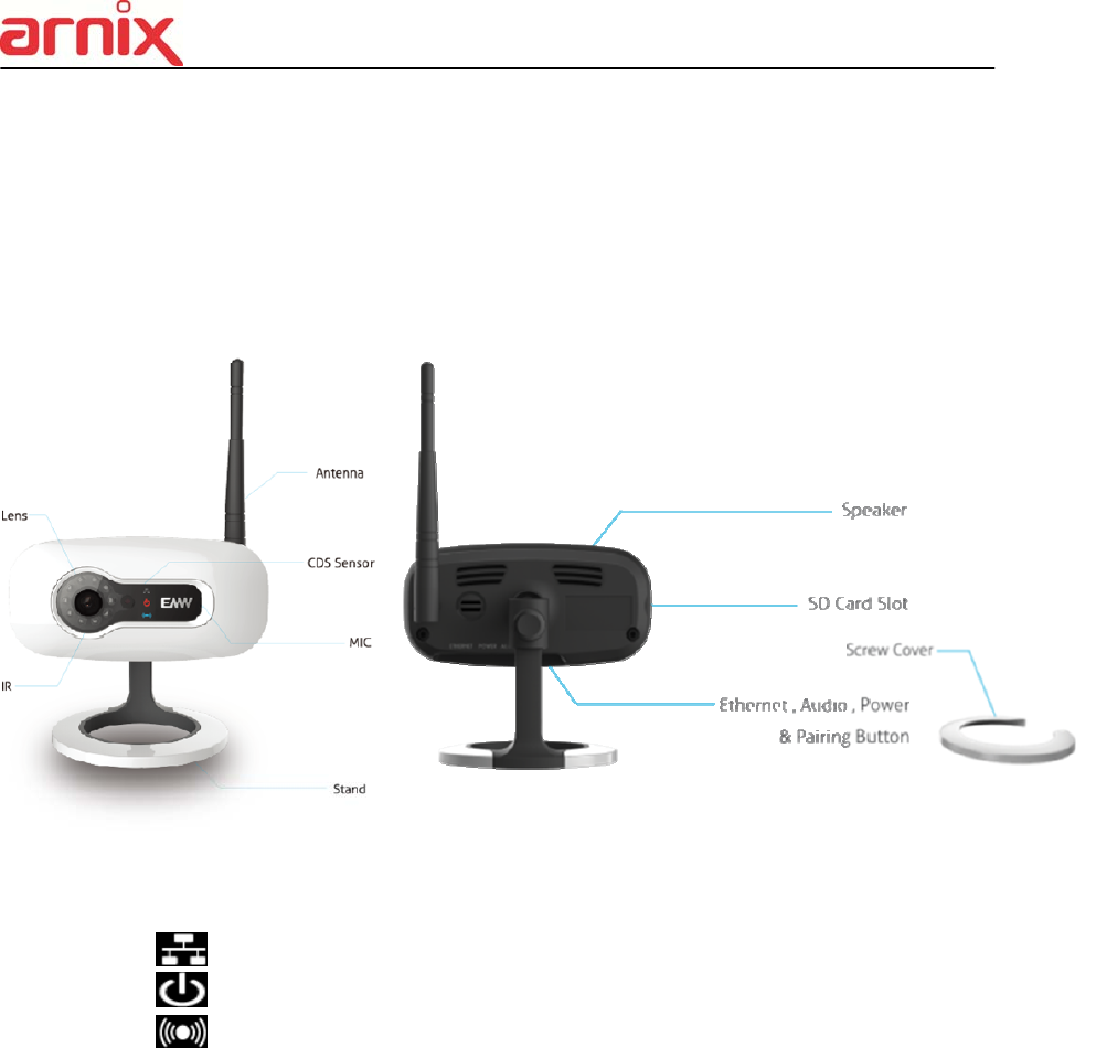
1. IP Camera
1) Front
- : Turned on when wired network is connected and properly working
- : Turned ON/OFF when power is ON/OFF
- : Turned ON/OFF when wireless network is connected and properly working
2) Bottom
- Ethernet : RJ-45 (10/100BASE-T) Ethernet port
- Power : DC 12V power socket for IP Camera
- Audio : Audio input socket
- Wired/Wireless switch button : Wired/Wireless network switch button
11
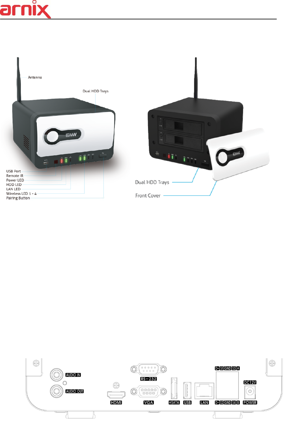
2. NVR
1) Front
- USB Port : For data backup/firmware update using flash drive and USB mouse
- Remote IR : For remote controller
- Power LED : Turned on when the power is on
- HDD LED : Turned on when HDD is running
- LAN LED : Turned on when wired network is connected and properly working
- Wireless LED 1-4 : 1-4 LED will be turned on when wireless network is
Connected and properly working
- Pairing Button : Push this button to initiate a automatic IP address scan and to
connect
2) Back
12
- Audio IN/OUT : 1 connector for audio input/1 connector for audio output
- HDMI Out : Video (HDMI) output
- RS-232C Port : RS-232C port for program updates and debugging
- VGA Out : Connector for VGA monitor
- eSATA Port : 1 External SATA terminal
- USB Port : Connector for Mouse or Backup
- LAN Port : RJ-45 10/100/1000BASE-T Ethernet connector for network function
- Alarm Out : Alarm device connection
- Power : DC 12V for NVR
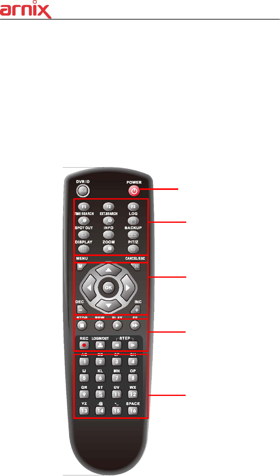
3. Remote Controller
① NVR ID ② Power
③ System Configuration Buttons
④ Navigation / OK
⑤ Playback Controls
⑥ Channel Buttons

13
NVR ID: Set the proper NVR System ID through which to operate. Press the ID button, and
then press the number button within two seconds to select the system ID of the NVR. If you
set the System ID to Zero, you can control multiple NVRs at the same time.
- Letters in Device
Allows you to create a unique name for each IP Camera, NVR, and put figures in set up
menu.
User can use the virtual keyboard or press the appropriate numeric button on the IR
Remote.
<On IR Remote Controller >
No 1st 2nd 3rd 4th 5th 6th
1 a b 1 A B 1
2 c d 2 C D 2
3 e f 3 E F 3
4 g h 4 G H 4
5 i j 5 I J 5
6 k l 6 K L 6
7 m n 7 M N 7
8 o p 8 O P 8
9 q r 9 Q R 9
10/0 s t 0 S T 10
11 u v U V
12 w X W X
13 y z Y Z
14 . @ . @
15 - _ - _
16 space
14
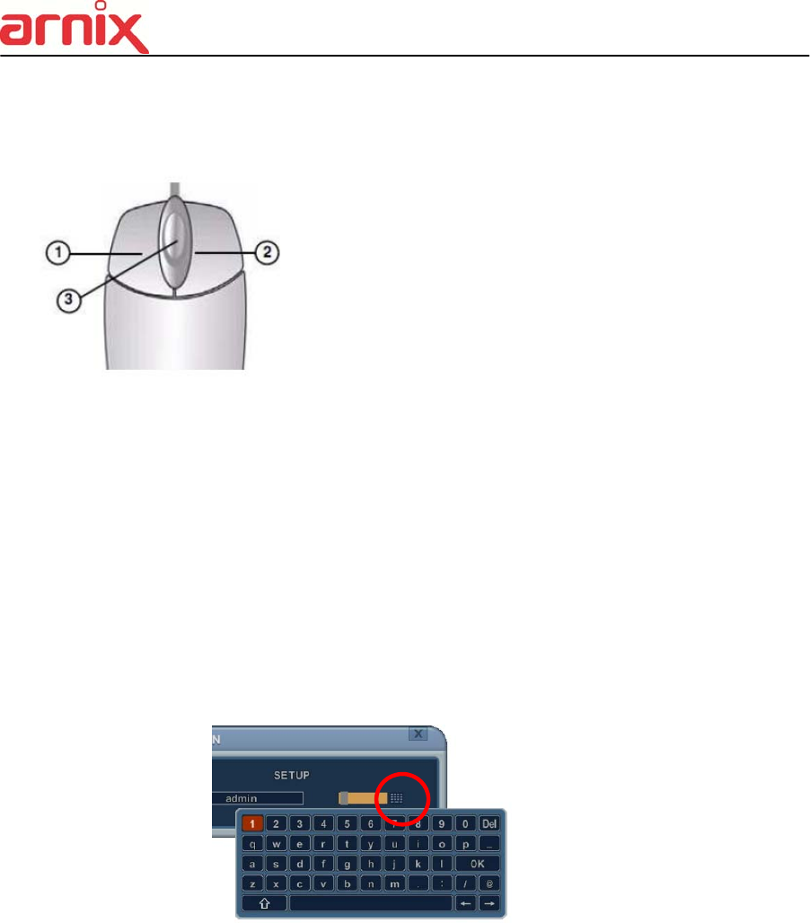
4. Mouse Control
NVR can be controlled by the mouse. Connect the
mouse to the USB port before use.
1) Left-Button -Double Click on any channel to enlarge
to full screen while in a split-screen display mode and
double click again to return.
Select the menu option while navigating through various
menu options.
2) Right Button- Right click anywhere on the screen to
open main menu. Double click to return.
3) Scroll Wheel: move the scroll wheel up or down to increase/decrease the value of the
selected menu option.
5. Virtual Keyboard for Mouse Control
Our system provides a virtual on-screen keyboard to perform the control by mouse.
Connect a mouse via USB port before using.
<Virtual Keyboard>
15
II. Getting started
1. Assembling the parts
1.1 IP Camera
1) Connect the antenna.
2) Hardware settings for Wireless network.
a. Check the Wired/Wireless switch for correct position (to Wireless)
b. Connect the power cable.
c. Wireless LED on the front will be turned on if the network has been connected and
properly working.
3) Hardware settings for Wired network.
a. Check the Wired/Wireless switch for correct position (to Wired).
b. Connect the LAN cable.
c. Connect the power cable.
d. Wired LED on the front will be turned on if the network has been connected and
properly working.
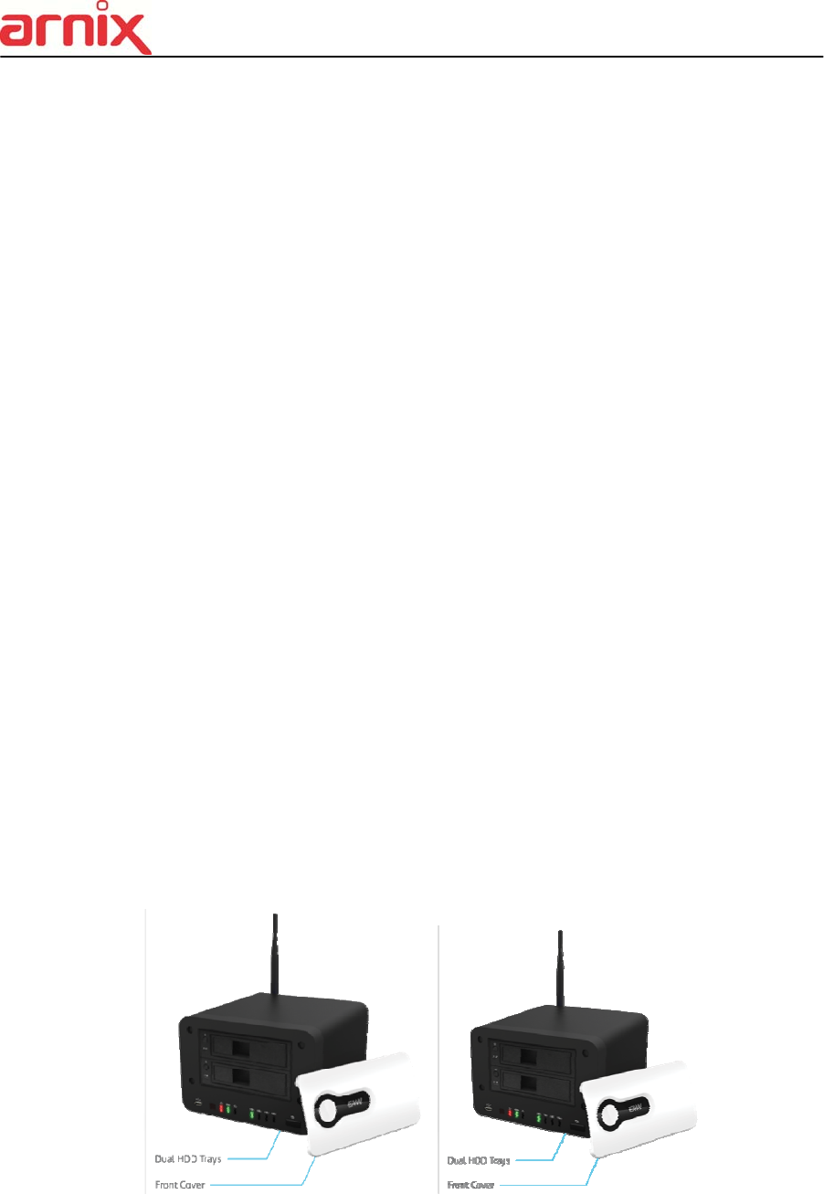
1.2 NVR
1) Connecting the devices
a. User must insert (slide in) the HDD, then press the power button to complete the
connection.
b. Connect the antenna.
c. Connect the power cable.
d. Connect the monitor and LAN cable.
16
2. Network Connection
2.1 Wireless Network
1) Connect the power to IP Camera and NVR. Please wait awhile until the booting
process is finished.
2) Push the pairing button on the front panel of NVR for more than 3 seconds to establish
the wireless network. Wait until the LED on the front panel changes from blinking red to
green.
<Caution> Pairing sequence must take place if you are connecting the IP Cameras
to NVR for the first time.
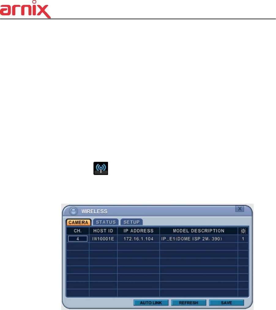
3) After finishing the wireless network setting, user must allocate the channels to the IP
Camera(s).
Find Wireless icon on the main menu, then enter the menu to select the IP
Camera(s) from the list. User can either allocate channels to the IP Camera(s)
automatically by pushing [Auto Link] button, or allocate the channels manually.
17
2.2 Wired Network
1) Connect the power to IP Camera and NVR. Please wait awhile until the booting
process is finished.
2) Use the Network Router to connect the IP Camera(s) to NVR.
3) Move to the Device menu and find LAN PORT SETUP menu to enter.
4) User can manually allocate channels to the IP Camera(s) on the list at LAN PORT
SETUP menu.
3. Time & Date setting for the first time
When the NVR is powered on for the very first time, the time and date are set as default to January 1st,
2009 Thursday 01:00:00. Before start operating the NVR, it is imperative to set the time and the date.
Move to the system menu to enter the setting.
18
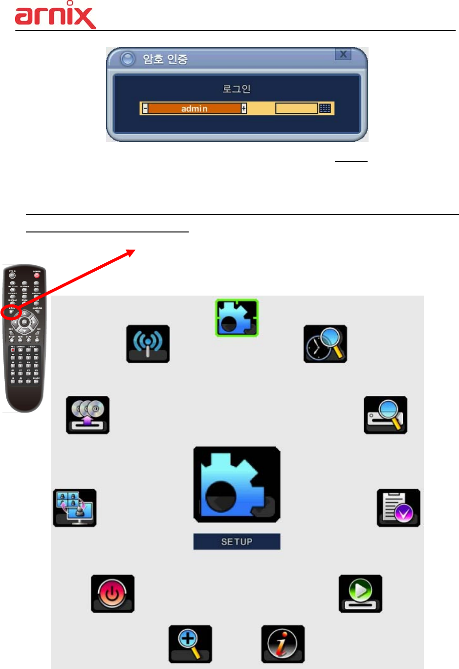
Log in ID is set to "admin" as default and the password is set to “000000” as default.
Main menu can be entered into by pushing [MENU] button on the remote controller or by
clicking right button on the mouse.
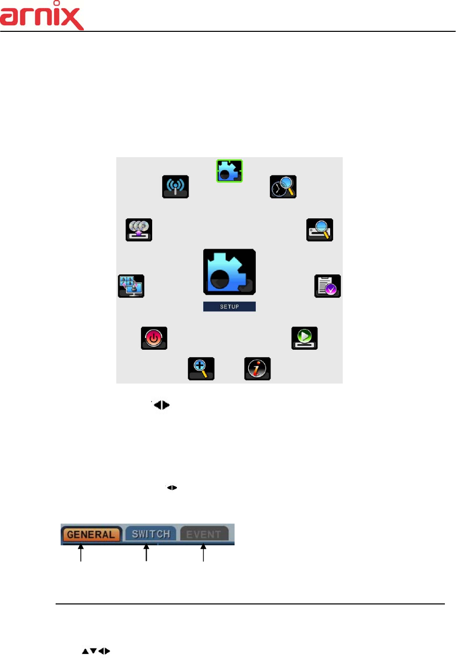
Setup
Time Search
External Search
Power
Zoom System info.
Playback
Log
Display
Backup
Wireless
19
4. Recording
4.1 Formatting the HDD (In case of initial HDD installation)
Move to the DISC manager menu (Main menu SETUP DISC).
① Use Up/Down, Left/Right [,] buttons to select the device and use [-, +] buttons to
select the proper options.
② In order to start the recording, HDD must be formatted (old data on the HDD will be lost by
formatting).
③ User is set for recording once the formatting process is done.
4.2 Recording method
User can immediately start recording by pressing the [REC] button.
Move to the Recording menu (Main menu SETUP Recording) for advanced settings.
<Note> Please refer to the Recording section on the manual for advanced settings.
20
5. Playback
5.1 Playback method
User can play the most recently recorded data by pressing [Play] button.
User can also play the recorded data by pressing [Time Search] button.
User can also reach the Playback mode through [Time Search] menu and
[Playback] menu on the Main menu.

21
III. LIVE VIEWING
1. Display Overview
1. Recording Mode
Background color of Number will be different based on the recording status.
1) Red - Event (Motion/Alarm) Recording
2) Yellow - Continuous Recording
3) Black - No Recording.
2. Event Indicator
(1) Indicate Alarm In terminal is triggered by an alarm sensor.
To appear Alarm window, press [UP] button. This button toggles between Shows
or Hide the Alarm Window.
(2) Indicate Motion detected. To disappear, press [ESC] button.
(3) Indicate Video Loss during Recording. To disappear, press [ESC] button.
(1) (2) (3)
22
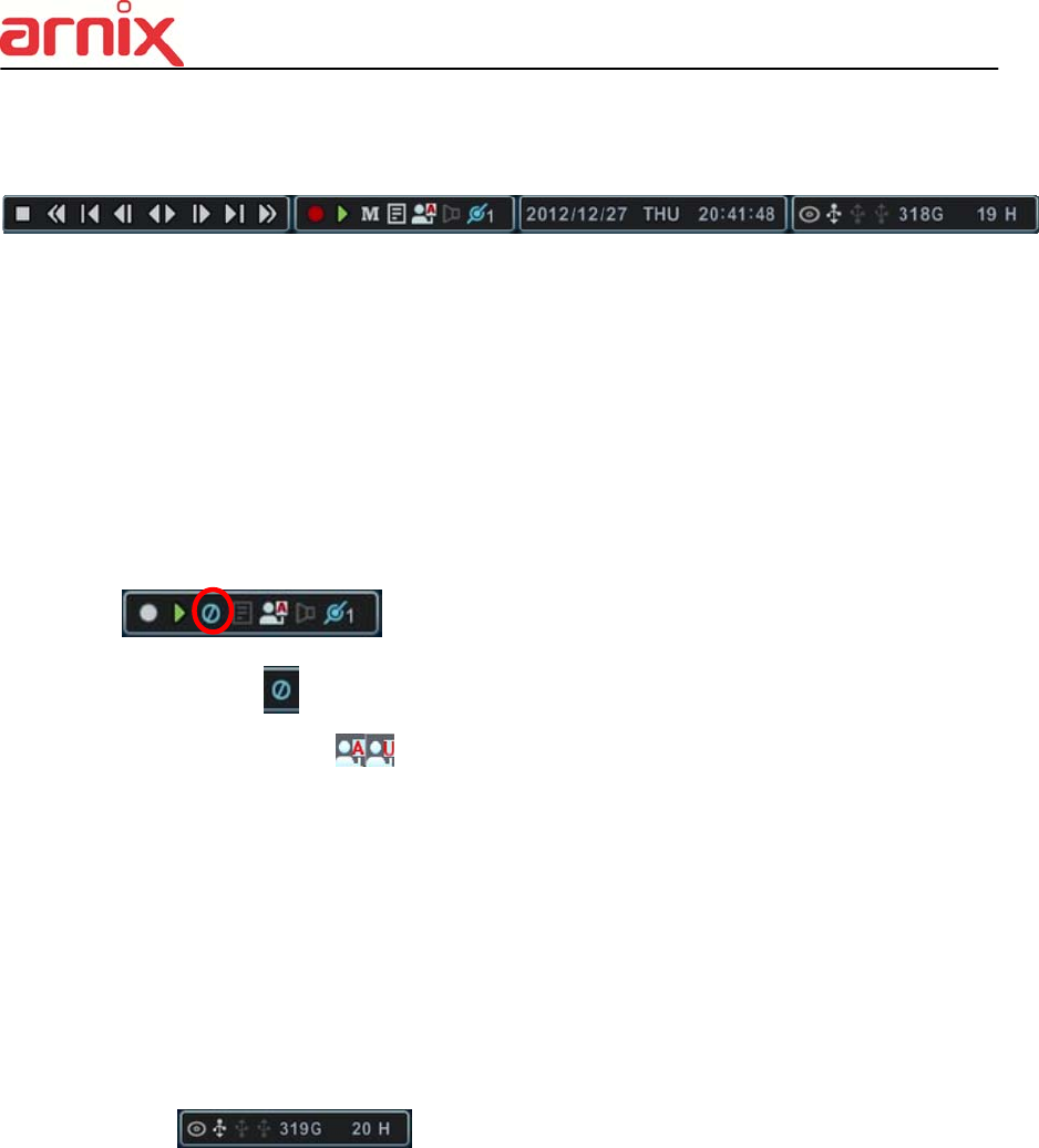
3. Status Bar
(1) This ICON will be shown only on play back mode.
(2) Indicate Recording Status. Red is recording. Click this ICON to toggle
Record Start and Stop.
(3) Indicate Playback Status. Green is Playback. Click this ICON to toggle
Playback Start and Stop.
(4) Indicate Menu. Click this ICON to popup the menu.
(5) Indicate LOG. Click this ICON to popup log history.
=> After click Menu and LOG, the status bar is changed like below picture.
Please click ICON to clear Menu and LOG.
(6) Indicate Login ( ) or Locking status. Click this ICON to toggle Log in and
out.
(7) Indicate Audio Data is stored the selected time during playback and turn to
blue color.
(8) It shows Number of Client, which is connected to Network.(MAX:10)
(9) Displays Month, Year, Time and Date. Change the order on System>Time.
(10) Indicate an USB Device is connected on Front panel and Rear panel.
It’s changed to blue color while it’s doing backup. Click this ICON to toggle Back
up Start and Stop.
(11) : Show you the remaining recording time of the NVR. If
remaining HDD capacity is less than 5GB, this blue “Recycling” icon will be
shown up.(DVD icon would not be shown some models if DVD-RW is not
supported)
(1) (2) (3) (4) (5)(6)(7) (8) (9) (10) (11)
23
2. Multi-screen Display and Sequencing
2.1. Screen Display.
Select any camera for Full screen display by pressing the Number button of the
desired camera. For 12ch, press 1 and then 2.
2.2. Multi-screen Display and Switching to Sequence Display.
1) Press [DISPLAY] buttons to activate the multi screen display. It is changed in the
order as shown below among your choice of SPLIT MODE.
2) To start Auto Sequence display, press [DISPLAY] buttons for 2 seconds and full
screen sequencing will be started.
Click this ICON by Mouse or SPOT OUT button on the remote control,
you will see following virtual controller
Main Monitor
3) The Auto sequence mode and dwell times are programmable in Switch set up.
For detailed information about configuring those, see “Switch Setup”. If the
sequence mode is not activated, it moves to Quad mode instead of Sequencing.
4) The Split mode is programmable in General set up.
3. Quick button for multi screen Display.
SPLIT MODE
In Auto Sequence Mode
Push to activate Auto Sequence
24
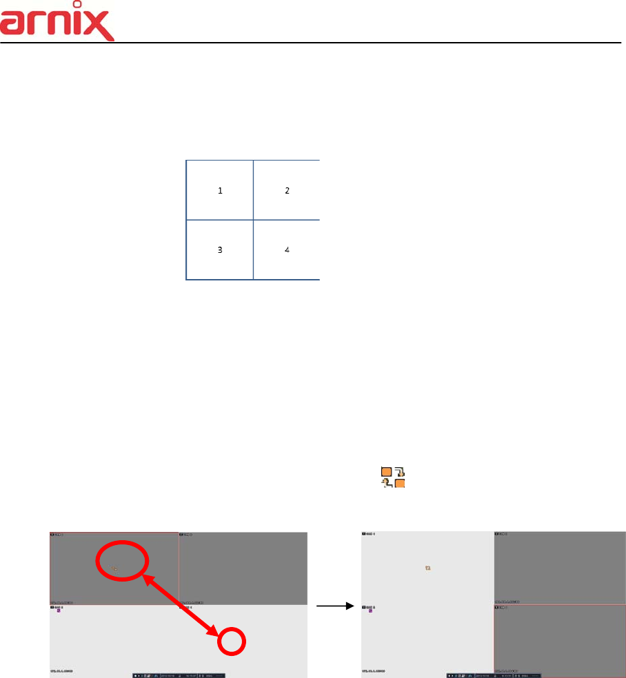
3.1. Quick multi split mode change
- Press F1 button on the remote controller + <Number>
For example, press F1 button then number 4.
The four channel view mode will be displayed.
<Note> BHA-WP200 model supports only 4 channel display.
3.2. Repositioning
It is possible to reposition the camera from a window to another window.
① Press F2 button on the remote controller. Mark will be displayed.
② Press Numeric button you wish to switching display.
③ Press [MENU] button to exit here with saving changes.
Press [Cancel] to exit without change.
Press [DISPLAY] button to rearrange.
4. Zooming
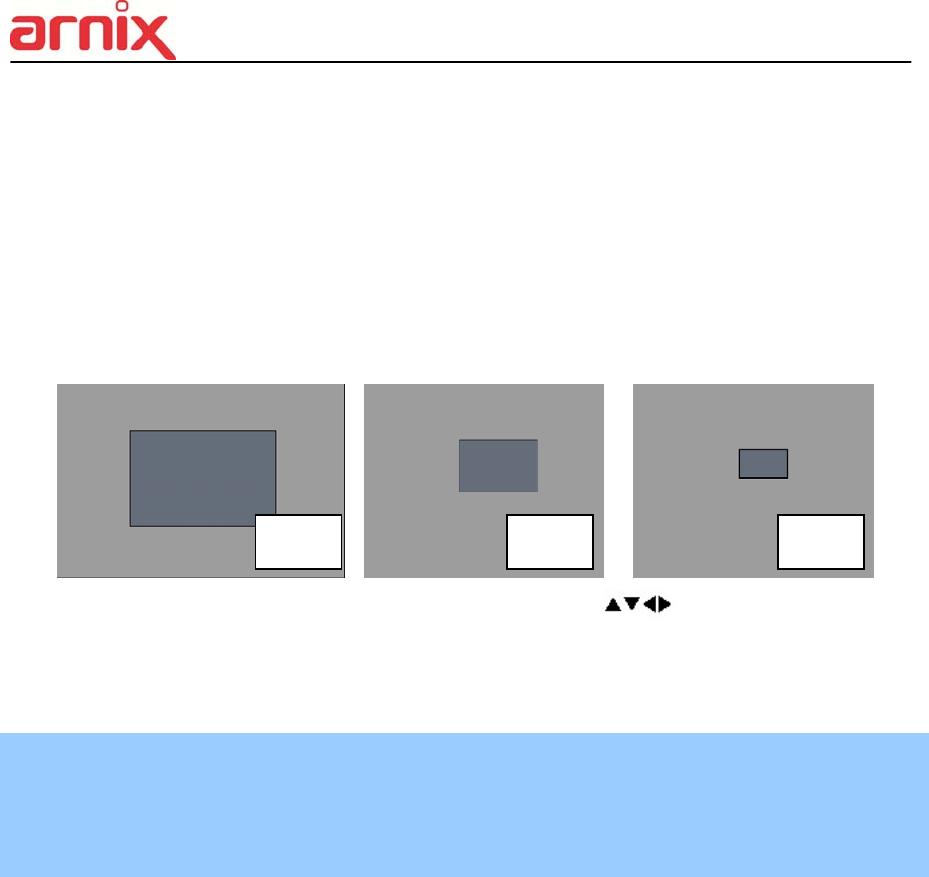
25
During live view mode, it is possible to zoom into a section of the screen to get a close-up
view of the screen.
1. To activate the digital zoom, select the full screen display of the camera you wish to
zoom.
2. Then press the [ZOOM] button on IR Remote controller. Zoom area box pops up, as
shown below.
3. Move the box to the desired position using Direction [ ] buttons.
4. Press [+] button to enlarge the image. Press [ - ] button to zoom out the image.
5. Press [ESC] button to return normal mode.
<Note>
If the Zoom button is pressed while in a multi-screen display, zoom operation is not
activated.
x 2 x 4 x 8

26
IV. OPERATION
1. LOG IN/OUT.
You must log on to the NVR with valid password to operate the NVR. By default, it comes
with one login account; ADMIN and the default password is “000000”.
<Note > If you are logging on for the first time, the system does not prompt you to change
the default password. Therefore, it’s strongly recommended to change the “PASSWORD”
when you install the NVR. Refer to [System Setup].
1. Login
1) On the front panel or remote control, press the power button.
2) When the NVR is powered on, it will start to scan NVR status.
3) Live Viewing screen will appear after initialization about 50sec. It can be delayed
when you have defect HDD, it will try to fix for logical problem but it will show you
warning message for physical problem.
4) On the remote control, press Login. Using the mouse, click the login icon, login
dialog box pops up.
5) Login Icon will be changed on status bar.
2. Logout
On the remote control, press LOGIN. Using the mouse, Press Login icon again,
indication you are logged off.
27
2. NAVIGATION THE MENU
1. Log on the NVR at admin level or user with configure level.
* User with configure feature is limited to access [DISK and System Menu].
2. On the front panel or remote control, press [MENU]. Using the mouse, Right click
wherever on monitor, Menu will be appeared.
3. Use Direction buttons [ ,+/-] to select the desired menu. Using the mouse, click
the menu. Items selected.
4. Press [OK] button to select the menu and display Sub-Menu. Using the mouse,
double click.
5. Use Left/ Right buttons [ ] to select on TAP menu. Selected items changed into
[Orange] color.
* It is automatically saved changes when you move between TAP menus.
6. The menus are displayed with options on the left-hand column and settings in the
right hand column. A cursor (highlighted menu) can be moved using the Direction
buttons [ ] .
7. Press [-, +] or wheel button to change the value or select options. By mouse, using
Wheel.
8. Press [SAVE] button to exit a menu with saving changes.
Selected Not selected Inactivated
28
Press [ESC] to exit a menu without changes.
V. SETUP
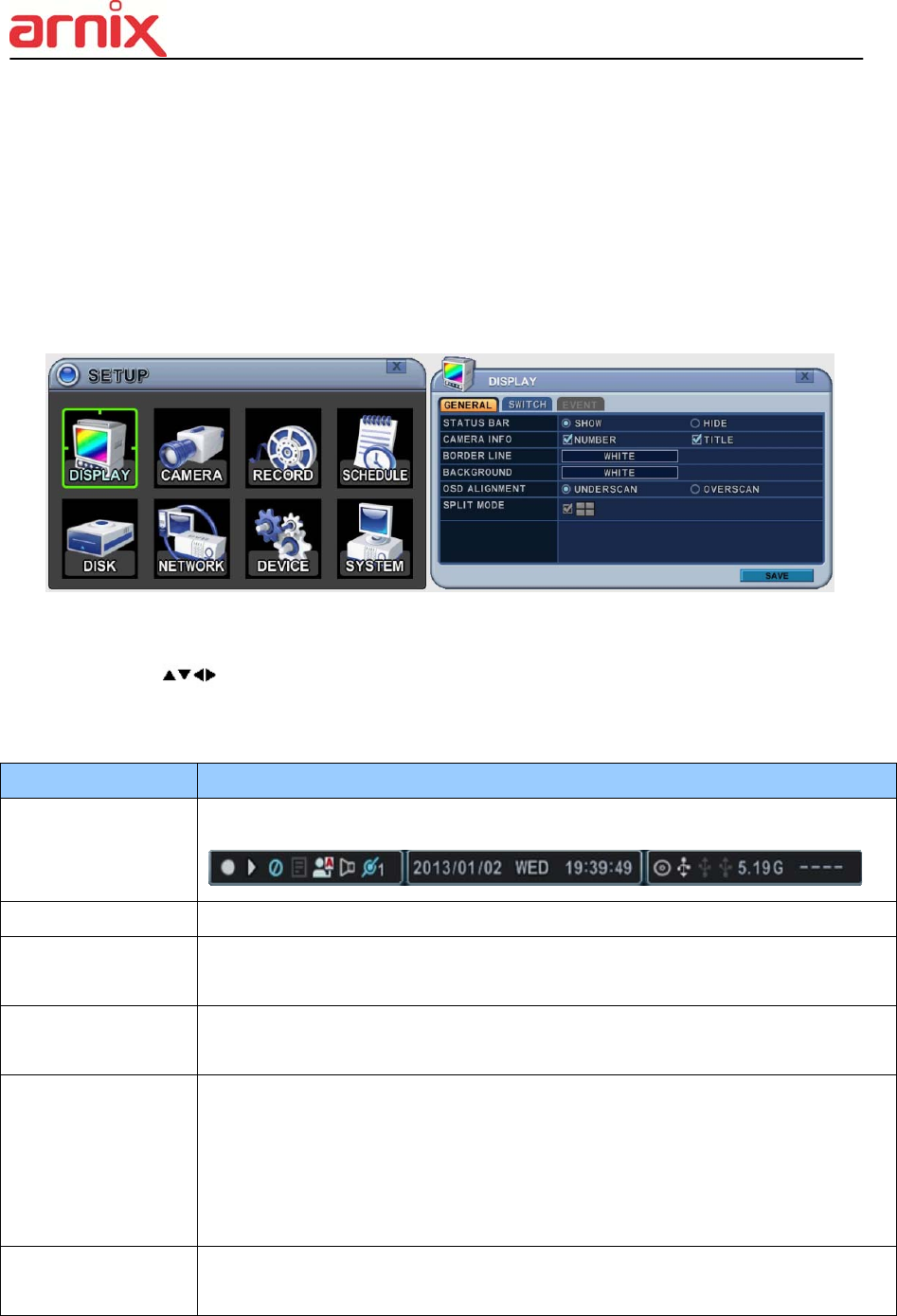
1. DISPLAY
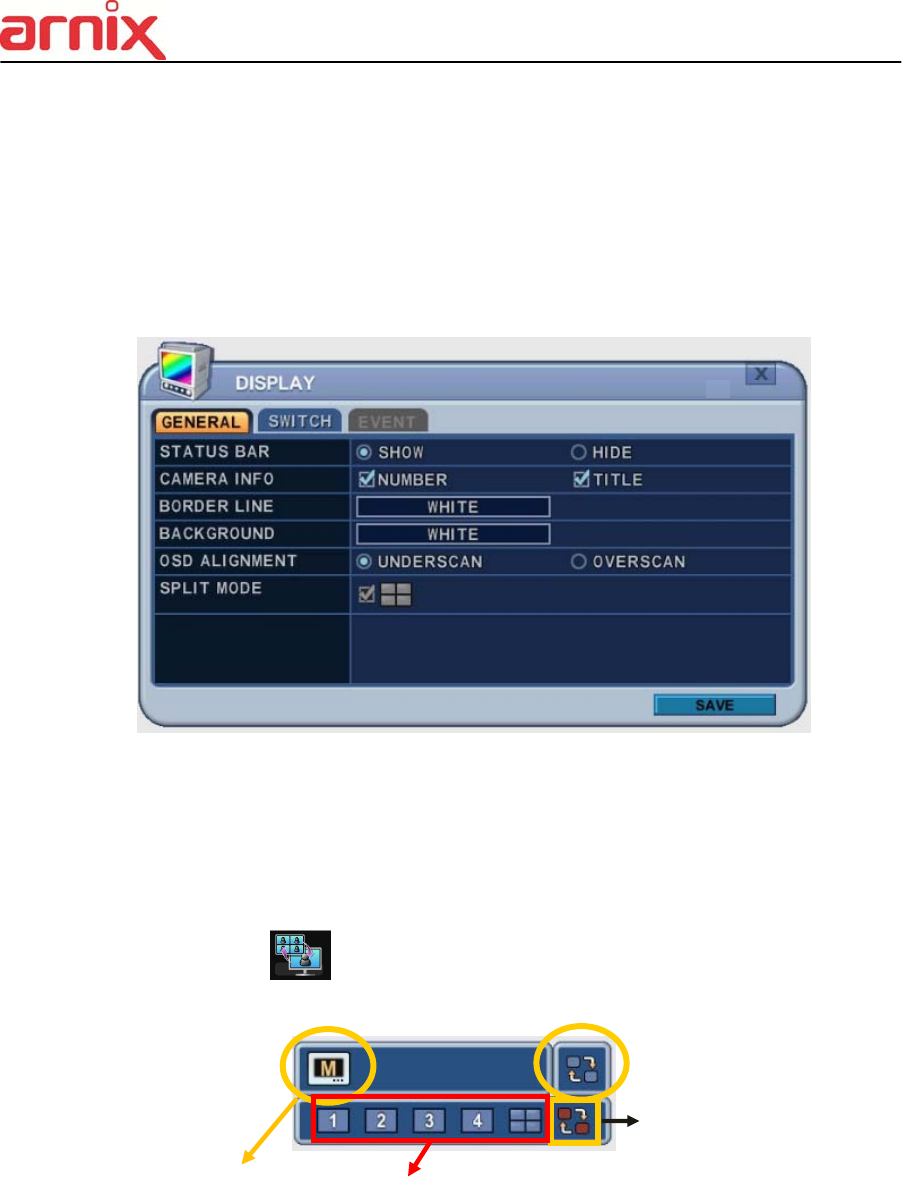
1.1. GENERAL
1. The menus are displayed with options on the left-hand column and settings in the
right hand column. A cursor (highlighted menu) can be moved using the Direction
buttons [ ] .
2. Change below options using [DEC/INC] buttons.
ITEM ADJUSTMENT
STATUS BAR
Select “Show” or “Hide” below status bar on Main Monitor.
CAMERA INFO Select On-Screen-Display information for Camera Number and Title.
BORDER LINE
Select Board Line between cameras.
[GRAY WHITE BLUE BLACK DARK GRAY]
BACKGROUND
Select Background color on NO VIDEO status.
[GRAY WHITE BLUE BLACK DARK GRAY]
OSD ALIGNMNET
The main video output can be displayed on a VGA and analog monitor.
Video can be displayed on both monitor simultaneously. Select On-
Screen-Display coordinates on Monitor.
- Under scan: Displays properly at CCTV Monitors
- Over scan: Displays properly at VGA Monitors.
SPLIT MODE
Display is changed the order as shown below among your choice of
SPLIT MODE.
3. Save changes and exit the menu, press [SAVE] button.
29
Exit the menu without making changes, press [ESC] button.
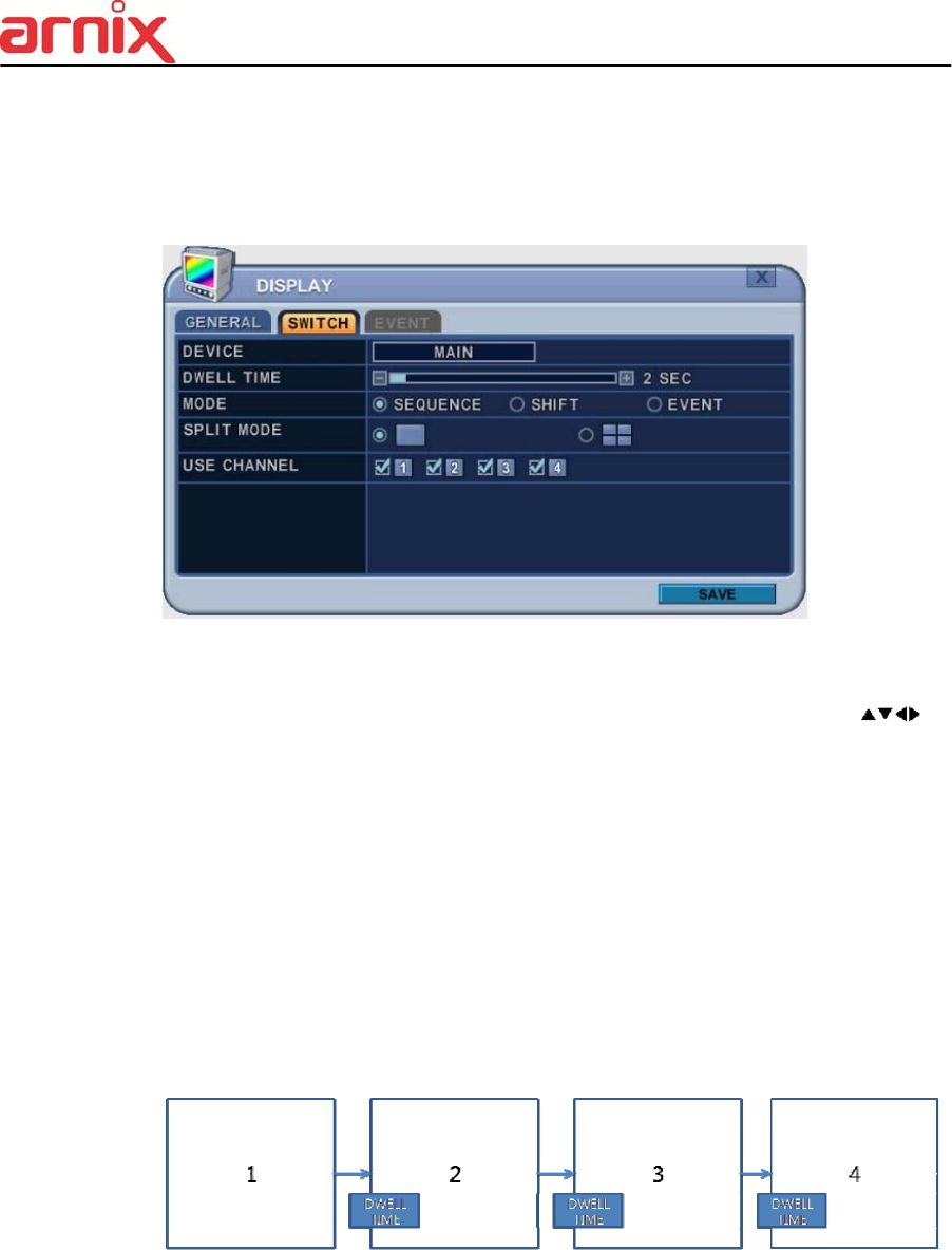
1.2. SWITCH Setup (Monitor Configure)
The menus are displayed with options on the left-hand column and settings in the right hand
column. A cursor (highlighted menu) can be moved using the Direction buttons [ ] .
1. Settings
1) Device: It is set by Main monitor.
2) Dwell Time: Select the interval that each camera or Multi screen mode is displayed in
a rotation. Use [-, +] button to change : [1 second ~ 30 second]
3) Mode: Select the appropriate monitor display to making any adjustment. This Mode
will be activated while it’s in Switch Mode.
a. Sequence: Automatic Sequence.
b. Shift: Selected camera will be displayed after dwell time.
c. Event: To display particular camera in full screen or in multi mode when event
triggered.
30
4) SPLIT MODE : Select desired sequence mode to switching.
5) USE CHANNEL: Select the cameras to be inclcuded or excluded from the automatic
switching.
2. Save changes and exit the menu, press [MENU] button.
Exit the menu without making changes, press [ESC] button.
3. Press [Display] button for 2 seconds to start Auto Switch cameras on Main Monitor.
Press [Spot] button then [Display] for 2 seconds to start auto switch cameras on Spot
Monitor
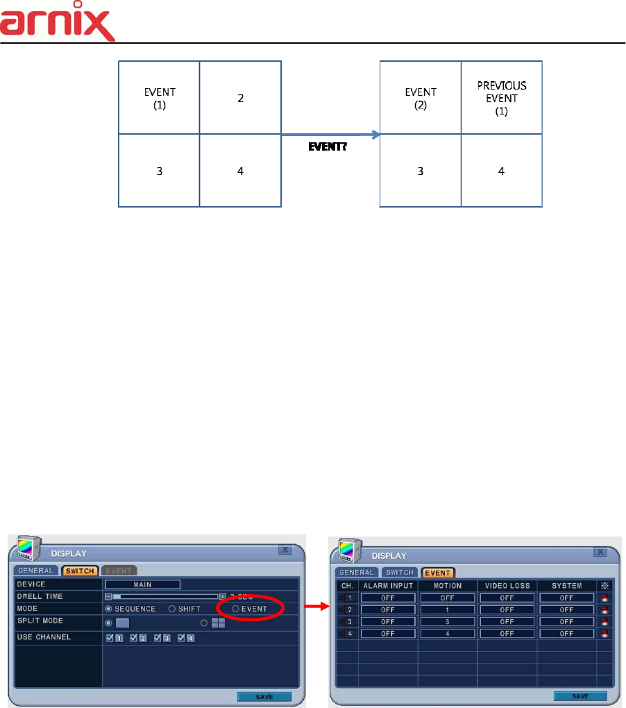
1.3. EVENT
This menu will be activated when you select <EVENT> Mode for Switch. Event menu will
allows customization of motion, alarm and video loss.
When selected event trigger such as alarm, motion or video loss, it will be displayed at the
monitor that is configured for event.
31
2. CAMERA
Press Left/Right buttons [ ] or number button to select the desired camera
Camera will be activated if IP Camera is connected. Camera Channel option is
highlighted and the camera settings are displayed.
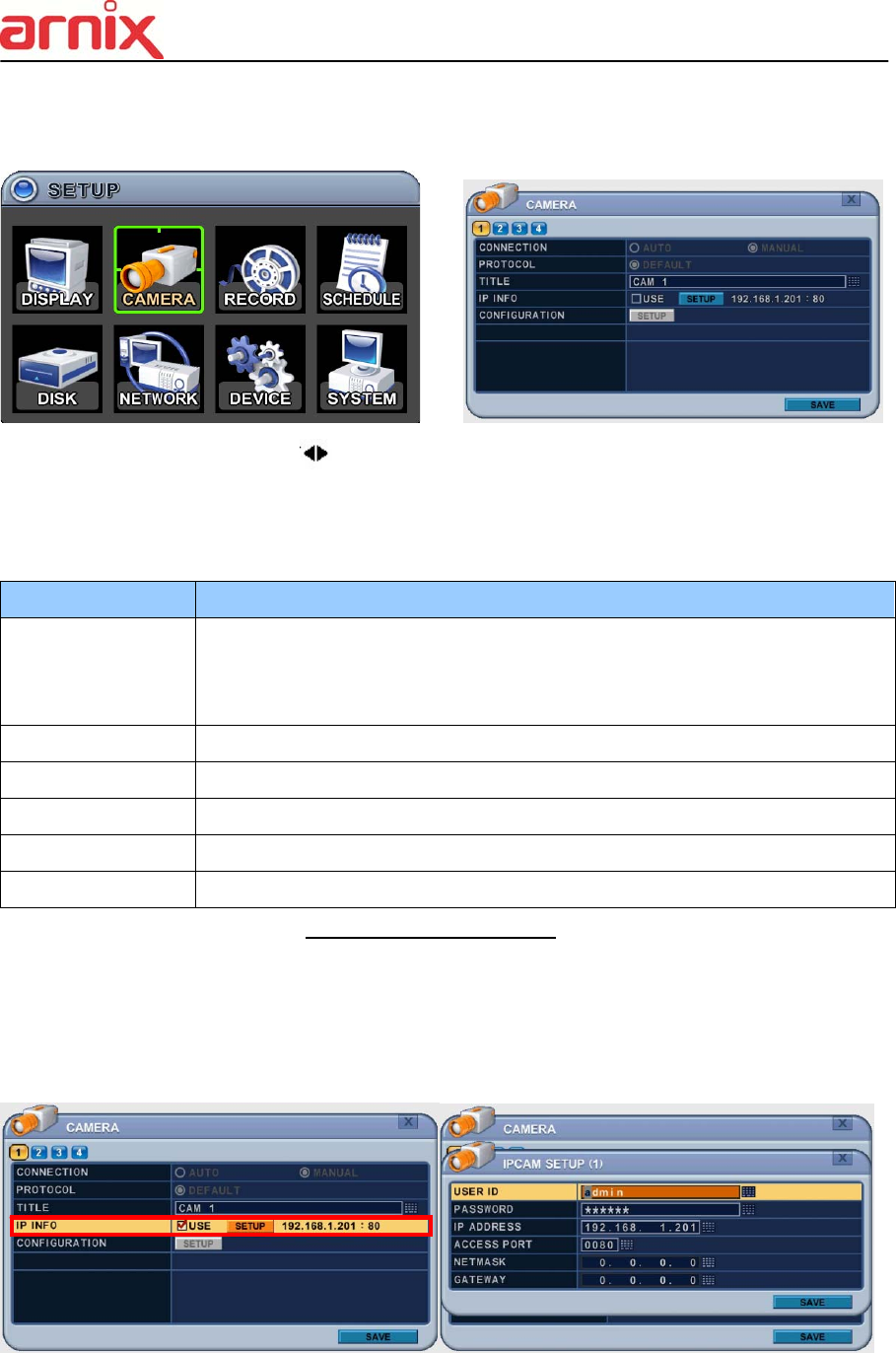
2.1. CAMERA
ITEM ADJUSTMENT
CONNETION
Select connection method
- Auto : BHA-WC100 Model does not support this feature.
- Manual : None PoE camera connection (LAN)
PROTOCOL Select camera type
TITLE Put the camera name
IP INFO Show camera brief information
CONFIGURATION .Set up details about camera
PTZ BHA-WC100 Model does not support this feature.
2.2. Set up IP camera MANUAL CONNECTION
1) Select “MANUAL” on connection after that USE check box and SETUP button will be
shown like below picture.
2) Select USE check box and press SET UP button to put IP camera information
3) Put user ID, PW, IP address and port of IP camera.
32
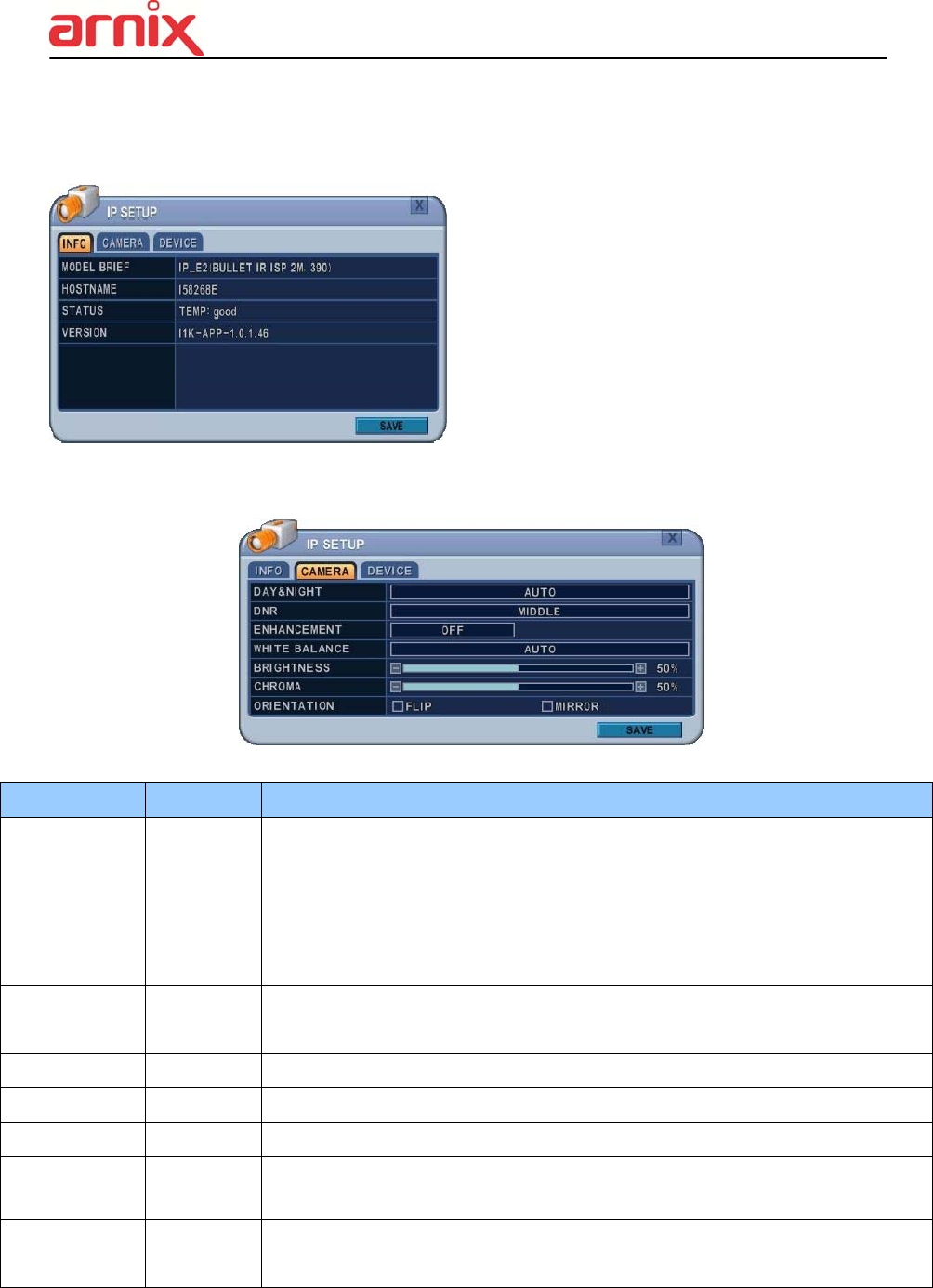
Press SETUP button on CONFIGURATION to see detail information or set up function of
camera.
1) INFO
MODEL BRIEF :
IP Camera information
HOSTNAME :
IP Camera’s own name
STATUS :
Show temperature of IP camera
VERSION :
: Show current version of IP camera
2) CAMERA
ITEM DEFAULT ADJUSTMENT
Day & Night Auto
Control True Day/Night (TDN) operation.
[Auto – DAY – NIGHT]
- When Auto is selected, the IR-cut filter will be off automatically in low-light scenes.
-When Day is selected, the IR-cut filter is on at all times.
- When Night is selected, the IR-cut filter is removed at all times.
DNR Middle
Improve picture performance in low light by reducing video noise. [ Off- Low-
Middle- High]
Enhancement OFF Select Off, BLC and WDR as a backlight revision.
White Balance Auto [ Auto - Auto High - Auto Low]
BRIGHTNESS 50% The brightness of each camera can be adjusted by pressing [-,+] buttons.
CHROMA 50%
The chroma of each camera can be adjusted by pressing [-,+] buttons.
ORIENTATION NONE
Set the way of reversing the image as up and down[FLIP],
left and right[MIRROR]
33
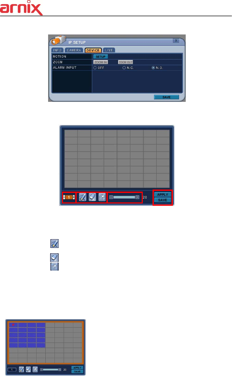
2.3. DEVICE
1) MOTION
Press SETUP button to set up motion function.
a. Motion Zone : Set up to 4 Motion areas defined by selected parts.
b. Motion Grid : The area property is highlighted and motion detection can now be
observed in the view window. By default, it’s set to OFF.
: Select All. Press [OK] to select.
: : Clear All. Press [OK] to select.
: Select specific. Press [OK] to select.
c. Motion Level : The sensitivity settings are : 1: Low sensitivity ~ Level 20: High
sensitivity. By default, the level is set to 10.
d. APPLY : Save changed set up.
e. SAVE : Save changed set up and exit automatically.
To define the motion view area cell-by-cell, do the
following:
On the front panel or remote control, press any of
direction buttons to highlight a cell in the motion
detection area, and then press [OK]. This area is
34
selected and the cells are highlighted in a blue color.
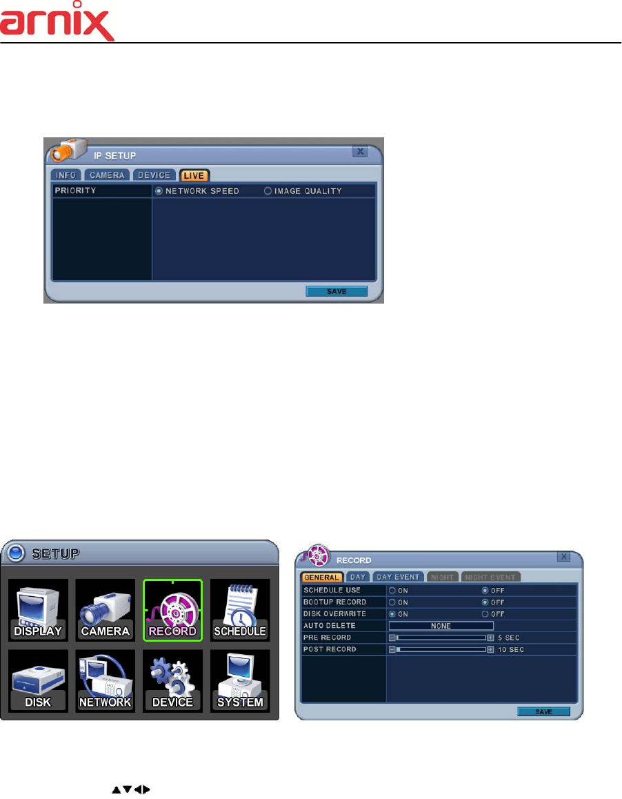
2.4. Live
1. Priority
1) Network Speed : Gives priority to network condition.
Preferred to unstable network environments.
2) Image Quality : Gives priority to image quality enhancement.
Preferred to stable network environments.
3. RECORD
3.1. Record General
1. The menus are displayed with options in the left-hand column and settings in the
right hand column. A cursor (highlighted menu) can be moved using the directional
buttons [ ] .
2. Change the options shown below using the [DEC/INC] buttons.
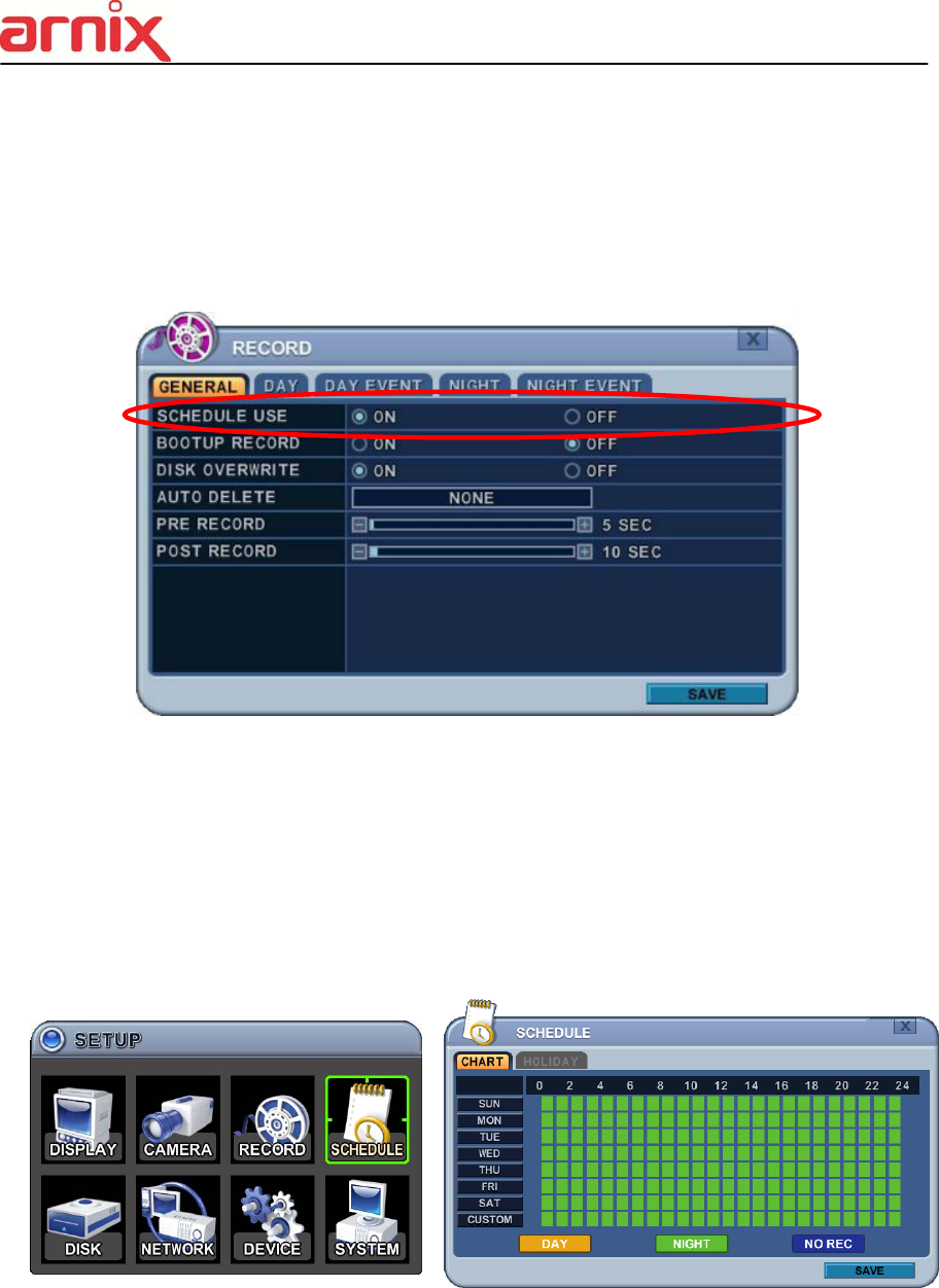
1) Schedule Use: This enables or disables Night Zone. By default “OFF”.
2) Boot up Record: The NVR starts recording without pressing the [REC] button
when it is set to “ON”.
3) Disk Overwrite: Selects the record policy of the hard disk drive.
- ON: By default, the hard disk drive overwrites from the beginning when it
becomes full.

35
- OFF: Stops recording when the HDD is full.
4) Auto Delete: Allows you to configure when the NVR automatically deletes all
data from HDD. It leaves the data for a selected duration from the current time.
[NONE 12HOURS 1DAY~ 6DAYS 1WEEK ~ 4WEEKS-> 30 DAYS]
5) Pre-Record: Determines the duration the NVR stores recorded video prior to
the beginning of Event Recoding [5SEC ~ 300 SEC]. By default 5 sec.
6) Post- Record: Determines the duration the NVR continues to record for after
an Event detection [5SEC ~ 300 SEC]. By default 5 sec.
<Note>1. Alarm/Motion Duration is extended if there is another Alarm/Motion detected whilst
Event Recording.
2. When recording, the Pre-Record and Post-Record will not be activated.
3. To save changes and exit the menu, select [save] then press the [MENU] button.
4. To exit the menu without making changes, press the [ESC] button.
3.2. Continuous / Normal Recording
The NVR comes with certain preset settings from the factory. Therefore, once the NVR
is installed immediate recording is possible by pressing the record button. By default,
audio, alarm, motion recording are off.
The NVR records video data continuously over a 24 hour period. Recording setup is for
normal recording. Different settings can be configured for each camera. To copy the setting
to another channel, press [Display] button.
ITEM ADJUSTMENT
Audio Select Audio Record ON/OFF

36
RES. Display selected resolution in MODE tab.
RATE Select recording speed for each camera.
QUALITY
Specify the record picture quality for each camera.
SUPER HIGH MIDDLE LOW
37
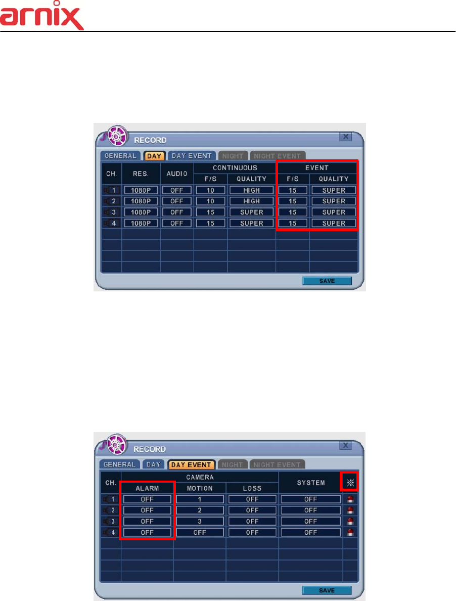
3.3. Event Recording
Users can set different event recording parameters on a camera by camera basis. Set the
continuous recording to [OFF] and configure the Event Recording speed and Quality for each
camera.
Determine whether Alarm, Motion, Video Loss is used for EVENT recording on the [DAY
EVENT] tab.
3.3.1 Alarm Recording
One Alarm input can be configured to one channel. One camera channel can be
assigned to multiple alarm inputs.
a. Press [-, +] button to change the value or select options. With a mouse, use
the wheel.
b. [※] indicates multiple alarm sources are selected.
c. Please refer to [Device/Alarm] for Alarm inputs and outputs.
38
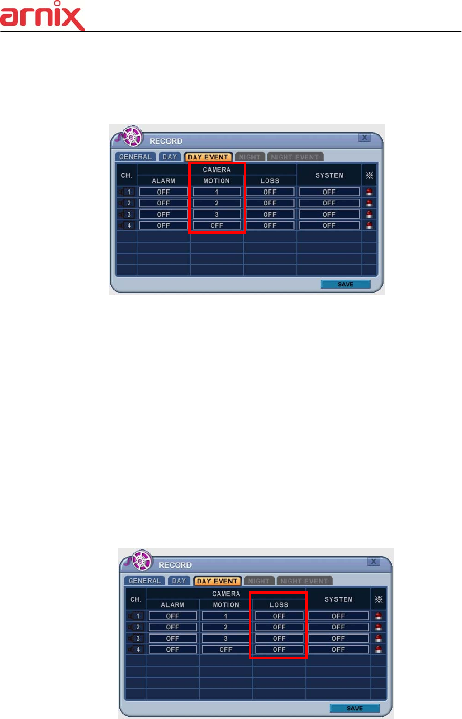
3.3.2 Motion Recording
One Motion detection can be configured to one channel. One camera channel can
be assigned to multiple motion detection.
a. Press [-, +] button to change the value or select options. With a mouse, use the
wheel.
b. [※] indicates multiple alarm sources are selected.
c. Please refer to [CAMERA] menu for Motion setup.
<Note> There may be cases when the recorder’s built-in motion detection function
does not operate properly due to the condition of the input video signal or other
factors.
3.3.3 Multi Event Recording .
1) Video Loss: When Video Loss occurs it can be configured to one channel.
One camera channel can be assigned to multiple Video Losses
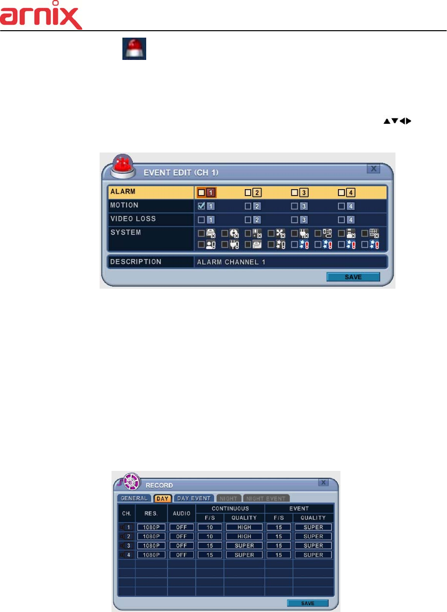
39
2) Event Edit
- Press [OK] to edit multiple events. The menus are displayed with options in
the left-hand column and settings in the right hand column. A cursor
(highlighted menu) can be moved using the directional buttons [ ] on the
IR remote or front panel.
- Change options using the [DEC/INC] buttons on IR remote or by clicking the
mouse button.
- System menu are not activated in this section
3.4 Continuous + Event (Motion/Alarm) Recording
Continuous and Event recording can be set simultaneously. The NVR records video
continuously over a 24 hour period, but if an Event occurs, the recording speed and
picture quality can be set to values different from continuous recording values.
<Example>
Pressing the REC button, Normal recording starts with High picture quality at 6F/S.
When an Event is triggered on this channel, it changes to record with Super picture
quality at 30 F/S. It reverts back to Normal Recording after the Event duration ends.
<Note> Please determine Event source, such as Motion, Alarm, Video Loss on the
[DAY EVENT] tab.
40
4. SCHEDULE
When the schedule is on, users can define their own daytime, night time, as well as
specified date settings. A schedule can be used to record selected cameras at different
times, change record rates, and select whether Alarm or Event is enabled. By selecting
Schedule Use “on” Record setup, Night Mode will be activated.
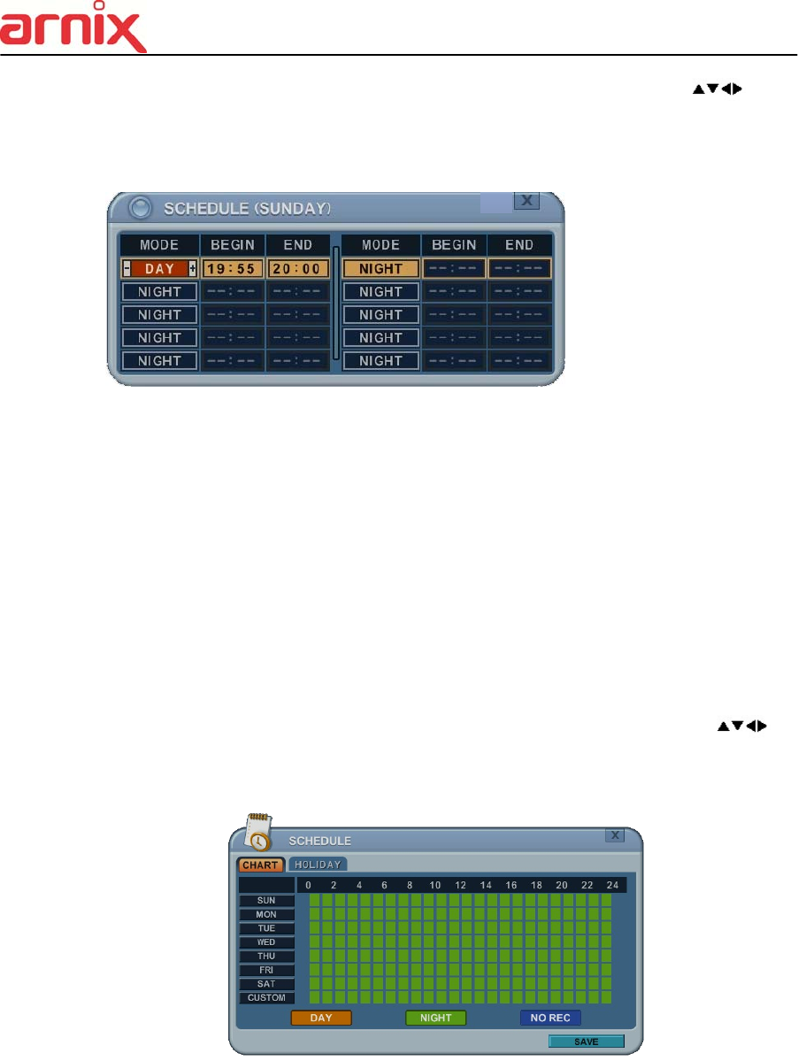
4.1. CHART Setup
The schedule chart shows a graphical representation of the defined record mode. Night
mode will be set by default. However, the schedules are only displayed if a corresponding
schedule has been configured in the schedule menu.
* DAY (Yellow): Follows day setting on record.
* Night (Green): Automatically follows night setting.
* No Record (Blue): The video is displayed, but is not recorded.
41
1) A cursor (highlighted menu) can be moved using the directional buttons [ ].
2) Select each day to configure, press [OK] or click the mouse button.
3) Detailed menu pops up for the selected day, as shown below.
a. Use [-, +] button to change the values.
Mode : [Night] [Day] [No Rec]
BEGIN: The time recording starts.
END: The time recording ends. The end time must not be before the starting time
or the same as the starting time.
b. Save changes and exit the menu, select [save] then press the [OK] button.
Exit the menu without making changes; press the [ESC] button.
4) Copying Schedule
a. A cursor (highlighted menu) can be moved using the directional buttons [ ] on
Day (Sun – Sat)
b. Press [Display] button on the desired setting.
42
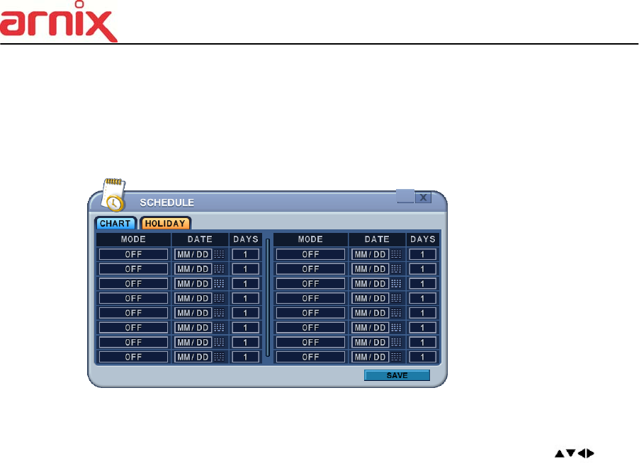
4.2. Holiday Setup
This allows you to create up to 32 holidays. If a holiday schedule occurs on the same date
as a weekday schedule, the holiday schedule overrides the weekday schedule.
1) A cursor (highlighted menu) can be moved using the directional buttons [ ].
2) Select each day to configure, press [OK] or click the mouse button.
3) Use the [-, +] buttons to change the values.
Mode : [OFF] [Day] [Night] [No Rec] [Sun~Sat] [Custom]
Date: The date Holiday starts.
Days: The holiday duration [1 to 15 days].
43
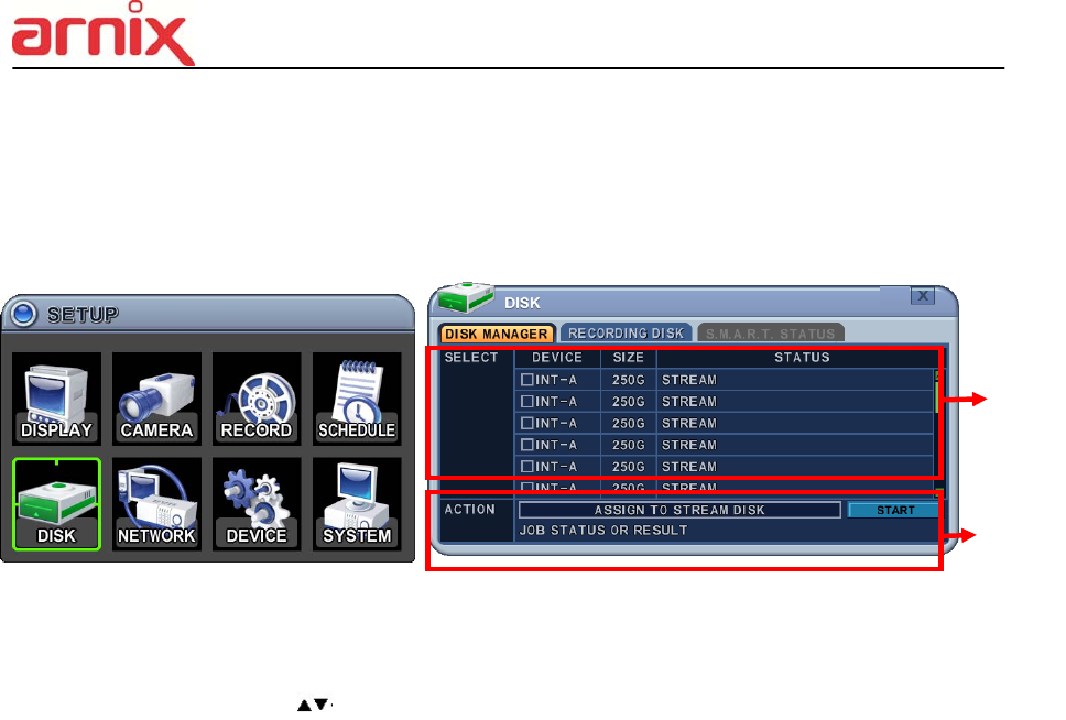
5. DISK
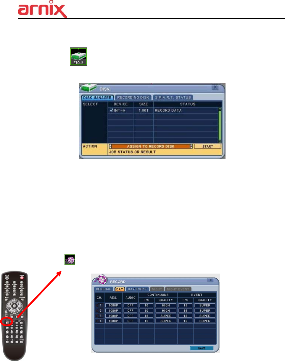
5.1. DISK Manager
Disk Manger is used to format hard disks and to assign the HDD usages, such as back up or
mirroring.
1. Select
1) The menus are displayed with options for all installed HDD’s or ODD list.
1) Press up/down [ ] buttons to highlight Hard Disk or ODD, then press [-, +] button
to select. Using the mouse, click the HDD option.
2) Device & Size: This information lists the installed drives and their respective
capacities, which is not currently used.
3) Status :
a. Unknown: New installed Disk.
b. Empty: Formatted but not used in current NVR.
c. CD/DVD: CD or DVD is installed for back up use.
d. Record Data: HDD stored Recording data but not used in current NVR.
e. Back up Data: HDD stored Back up data.
f. Other Data: Neither Back Up nor Recording Data, including AVI file.
<Note>: Disconnected Disks disappear from the Disk Menu.
2. Action :
1) None: By default.
2) Assign to Record Disk: Initialize the selected HDD. It formats the drive and all
data on the drive is erased. External SATA HDD can be used to extend HDD
capacity. Selected HDD will move to [Recording Disk] after formatting.
3) Mirror: Mirror on INT –A
: This NVR utilizes two internal/external HDD’s for recording. Writing duplicate
data to other HDD in order to protect against loss of data in the event of a device
failure.
*<Warning> This HDD must be same with or bigger than original size.
①
②

44
4) Assign to Record & Mirror: This menu is activated when you select two HDD’s
at the same time. It automatically configures one HDD for Recording and the
other for Mirroring.
5) Initialize for Back Up:
Selected device, such as Media or External HDD, is formatted for backup use.
Here’s the guide for backing up data to various devices.
Once you press the start button, this pop-up window is displayed to ask you to
confirm the initializing for back up: YES or NO.
6) Link Record Disk
: This function is used for adding [used HDD] from the same model without
formatting.
< Note: There are limitations for using this function >
A. NVR should be empty (NO HDD). If RECORDING DISK’s exist it does not work.
B. The used HDD should be from same series. It does not work with different series.
C. There should be no time duplication in the HDD.
Device ODD (Media) HDD
CD/DVD±R CD/DVD
±RW
SATA USB
Media can be formatted x o o x
Device can be formatted on a PC using FAT 32, NTFS
File system.
x x o o
Media must be formatted on NVR before backing up or
exporting data to the device.
x o ᇞ ᇞ
<Note1> USB flash memory is working without format.
<Note2> if a FAT32 /NTFS formatted external USB device is installed, <Assign to
Record Disk> feature is disabled. It’s limited to back up only.
3. Press the [ +] button to start selected action.
4. Save changes and exit the menu, select [save] then press the [MENU] button.
Exit the menu without making changes, press the [ESC] button.
45
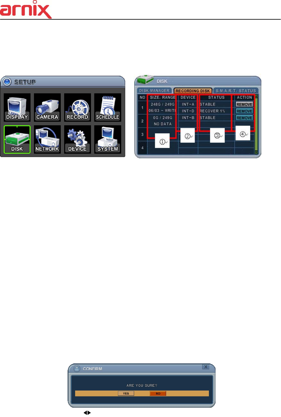
5.2. Recording DISK
This information lists the installed drives, how the NVR records video and their respective
capacities which are currently being used for recording.
1. Size, Range
: This displays current recorded data size, HDD size and indicated stored data range,
and where the writing progress is running
2. Device
Displays logical Master and Slave device in mirroring. Upper device is the Master and
the other is used for slave. If the slave HDD reaches 100% synchronization, Master
HDD can be removed as well.
3. Status
1) Stable: The HDD is in a stable condition.
2) Re-sync: Force all pending buffered disk writes to the NEW installed disk.
3) Recover: Recover all mismatched data between the mirrored disks.
4. Action: Remove HDD.
The “Are you sure?” dialogue box opens.
Press the up/down [ ] buttons to YES or NO, then press the [-, +] button to select.
46
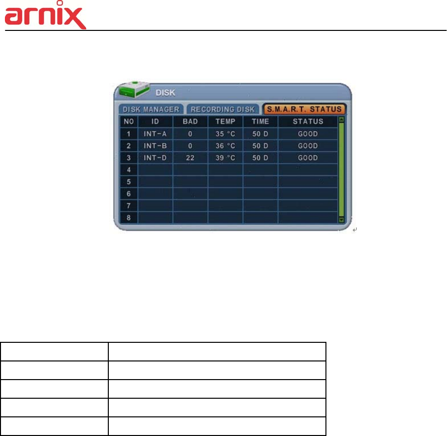
5.3. S.M.A.R.T STATUS
Displays HDD information, such as Bad Sector, Temperature and HDD running time.
S.M.A.R.T information has slight differences between depending on the HDD manufacturer.
We recommend changing the HDD if its status is in <PRE-FAIL>
*NOTE : Please refer to STATUS explanation
Status Explanation
GOOD GOOD
PRE-FAIL Alerts that may be a problem
PAST PRE-FAIL “PRE-FAIL” occurred before
FAIL Find problem / need to replace
47
6. NETWORK
A static service consists of an IP address that remains constant for the duration of the
contract of the internet service, whereas a dynamic service has an IP address that changes
every time a new connection is made through the provided modem, or recurrently in a given
period of time. Though most internet service providers offer both solutions, this manual will
distinguish between the two solutions, according to the commonly available service types, to
configure the NVR for the networking purposes.
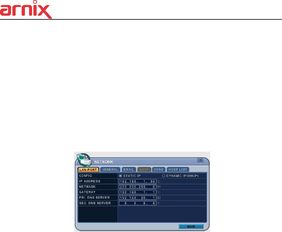
6.1. LAN Port & IPCAM Port
1. LAN PORT
1) Config : Select IP address type.
2) IP Address: Enter the static IP address
3) Net mask: Enter the IP address of the subnet mask.
4) Gateway: Enter the IP address for the internet gateway server.
5) PRI.DNS Server: Verify the name of the domain name system.
6) SEC.DNS Server: Enter the IP address of the backup domain name system (DNS)
server that the NVR will use to convert name to IP address. This server is used if the
primary DNS server fails.
<Note> if you do not set up the DNS server correctly, it will have problem with mail
sending.
2. DHCP Service : Select On or OFF to activate
: If user selects DHCP service on, available IP address is displayed in Net mask.
48
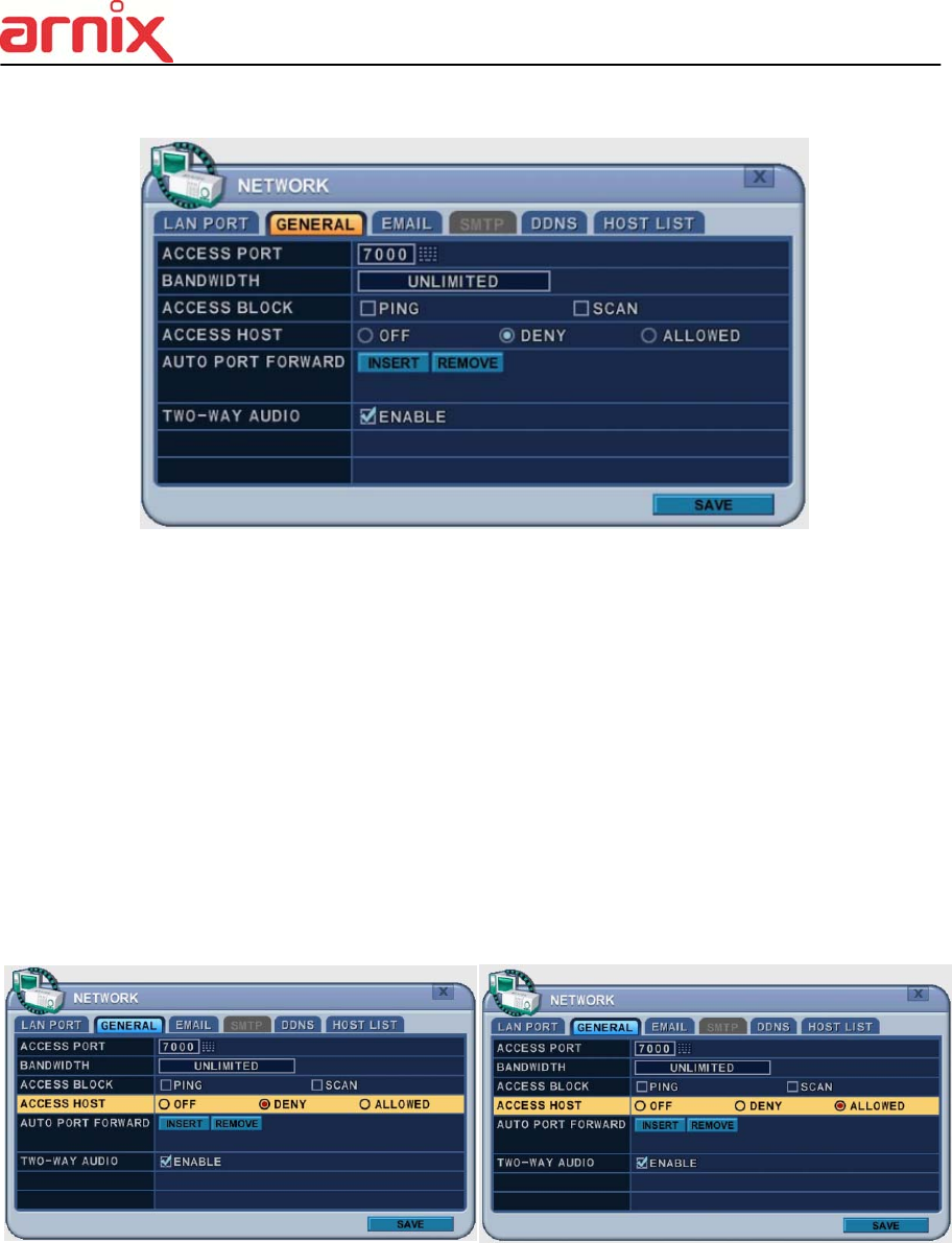
6.2. GENERAL
1. Access Port: Select “0001 ~ 9999”
Enter the port number the client uses to communicate with the NVR over the internet.
The default port is 7000. It is recommended to use a port above 1000.
2. Bandwidth: Select the network bandwidth to limit the amount of network resources
allocated to client connection. The default is unlimited: “ 4 KBPS ~ 8 MBPS”
3. Access Block 1) Ping Block: No response to ping. By default OFF.
2) Scan Block: No response to Auto Scan from EMS. By default OFF.
4. Access Host and Host List: Allows you to access or deny specific IP address.
To allow or deny remote access requires you to enter a range of IP addresses as an
IP address and mask. Host List will be activated when you select deny or allowed.
5. Auto Port FWD: Select the ADD button to automatically open ports for Router
communication with UPNP compliance.
6. 2 Way Audio: Support 2 way Audio between NVR and Remote Software
57
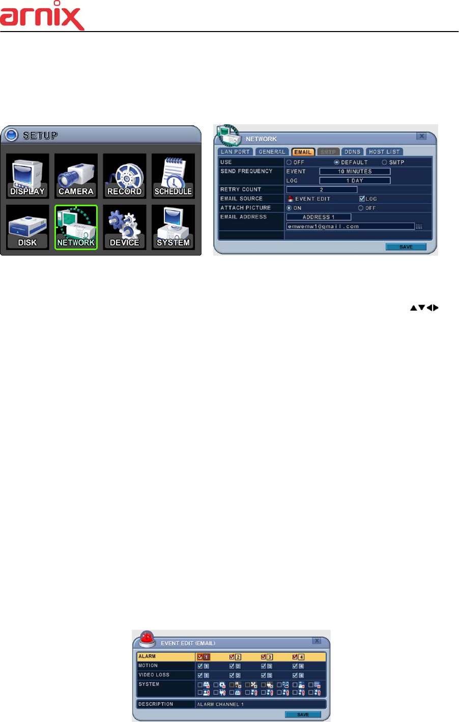
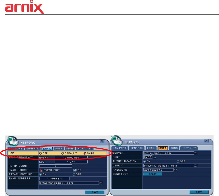
6.3. EMAIL
This NVR allows you to specify the events that generate notification. Sends e-mail
notification if an event occurs, such as alarm, motion detected etc.
The mail server can use either the NVR mail server or your existing e-mail settings.
The menus are displayed with options in the left-hand column and settings in the right hand
column. A cursor (highlighted menu) can be moved using the directional buttons [ ].
1. USE: Select the e-mail notification ON or OFF. The default is OFF. Press the [-, +]
buttons to select. Using the mouse, click the option to select mail server.
1) Default: Default it is provided by manufacturer. Mail notification options and mail
address settings are available.
2) SMTP: SMTP Configuration tab is activated to set up your own mail settings.
2. Send Period: e-mail will be sent at selected intervals.
1) Event: [Immediately, 10 Minutes, 1 hour, 1 Day]
2) Log: [1 Day, 1 Week]
3. Retry Count: Select the number of retry attempts to send e-mail after failure.
4. E-mail Source: Event must be specified using notification options.
1) Event Edit. Notifications can be enabled for each channel for Alarm, Motion, Video
Loss and System (HDD Fail, Record Fail, HDD Full etc.). Press the [OK] button to
select.
58
5. Log: This NVR will mail Log List at selected intervals.
6. Attach Picture: While in recording mode, a picture can be attached to mail.
7. E-mail Address: 5 mail addresses can be configured for mail notification.
6.4. SMTP
This menu is activated when you check <SMPT> on EMAIL.
The following settings are only needed if you are NOT using the NVR mail server.
1. Server: Enter the e-mail server name or IP address. To set server name, use the
virtual keyboard, or press the appropriate numeric button on IR Remote or front panel.
2. Port: Define the port the SMTP server will communicate through. By default, it is set
to 25.
3. Authentication: Check this <ON> if your mail server requires authentication.
4. User ID & Password: Enter the user ID/name and password for the SMTP Server.
(Distinguish Upper and Lower Case : use Lower case by Front or IR remote, press
[OK] button at this cell, virtual keyboard will be pops up.)
5. Send Test: Test to send e-mail.
6. Save changes and exit the menu, select [save] and press the [MENU] button.
Exit the menu without making changes, press the [ESC] button.
59
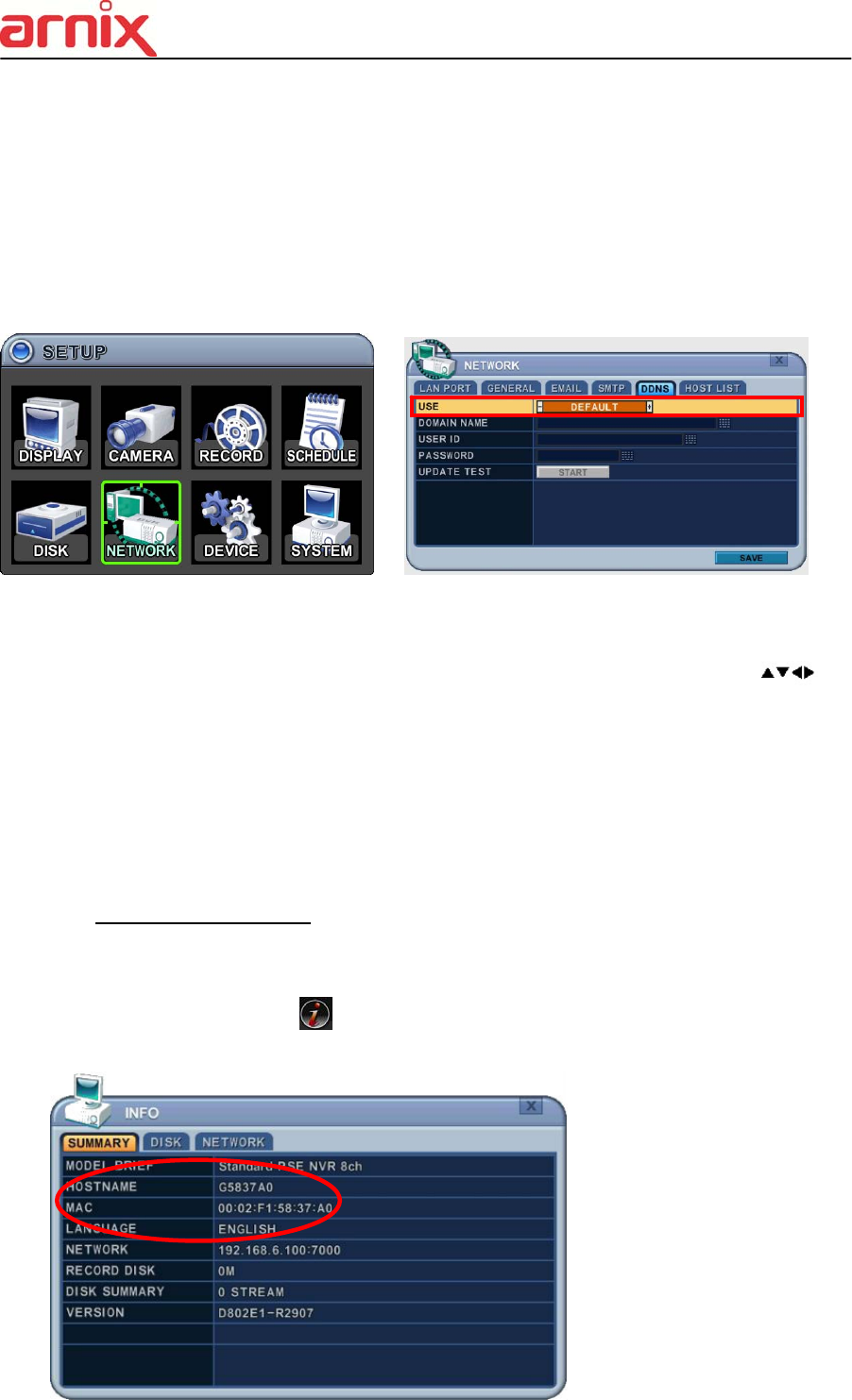
6.5. DDNS (Dynamic DNS)
This NVR offers free dynamic DNS update. It keeps track of your changing IP address. It’s
easiest to use.
The menus are displayed with options in the left-hand column and settings in the right hand
column. A cursor (highlighted menu) can be moved using the directional buttons [ ].
1. USE: Select one method among DDNS OFF, Default, DYNDNS and NO-IP.
The default is OFF. Press the [-, +] buttons to select. Using the mouse, click the
option to select DDNS provider.
1) Default: Default it is provided by manufacturer. We offer DDNS service for remote
at http://www.dvrhost.com
If you are using <Default> for DDNS, you do not need to setup anything. It does
not allow you to create a host name; it’s provided by the NVR. Press the [info] button
on IR remote or select icon on the menu, then check your host name and Mac
address.
For example,
http://G5837A0.dvrhost.com:
7000

60
2) DYNDNS: To use your own domain name service or “dyndns.com”
2. The following settings are only needed if you are NOT using the default.
1) Domain Name: Enter the name you set for the DDNS web configuration.
2) User ID: Enter your user ID.
3) Password: Enter your password.
4) Update Test: Click the Update Test button to confirm the connection. A success
message will appear.
3. Save changes and exit the menu, press the [MENU] button.
Exit the menu without making changes, press the [ESC] button.

61
6.6 Router & Port Forwarding
A majority of networks will often consist of a single IP address which shares internet access
through a router. This IP address may be any external (public) static IP address or any
dynamic IP address issued by the Internet Service Provider.
The purpose of a router is to enable multiple personal computers and any other devices that
require internet connection to access the internet simultaneously. Most routers by default
enable (open) commonly used ports so that mainstream applications such as Hypertext
Transfer Protocol (HTTP, Port 80), File Transfer Protocol (FTP, Port 21), Telnet (Port 23) and
Post Office Protocol 3 (POP3, Port 110) are used.
To solve the firewall problem, and let a visitor into the network, the user instructs the router to
allow traffic to pass through on a given port. This is known as Port Forwarding, as the router
forwards (directs) all internet requests on a specific port to the local machine. With port
forwarding, external visitors are able to connect to the NVR while other internal devices
remain protected.
Here is the example of NVR connection.
Network Router NVR IP Setting
PC Connect position PC Connect position
CF
① LAN ② WAN
A B C B C
Static IP
use
STATIC ○ △ X ★ ★
DHCP ○ ▲ X ☆ ★
Check the NVR IP of info
and set into Router.
x
STATIC ○ ○ ○ ○ ○
DHCP
N/A [Need Local DHCP
Server]
DHCP
use
STATIC ○ △ X ★ ★
DHCP ○ △ X ★ ★
Check the NVR IP of info
and set into Router
x
STATIC N/A
DHCP △ △ PPPOE is not supported

62
1) Description of Location.
A. LAN: Connect by Local IP. If you are connecting from within your network you only
need to enter the IP address of the system into the S/W (example 192.168.0.50)
B. WAN: Connect by DDNS. If you are connecting from outside your network use the
DDNS to configure the S/W (example L123456.dvrhost.com).
C. WAN: Connect by IP address. If you are connecting from outside your network and if
you know your Static IP address, use the IP address to configure the S/W (example
http://124.137.23.72:6000 ).
2) Description of Symbols.
○ : Connected.
x : Not able to connect
△: There’s some limitation - depends on Router or Network connection
★ : Need to use Port Forwarding
3) Description of Colors.
Yellow - Recommended
Grey - Not available
White – Depends on Router or Network condition.
2. How to use NVR for DHCP
<Note> Each Router has different port forwarding settings. Please refer to the router manual
or contact to your router manufacture for assistance
Internet
: DHCP
DVR: DHCP
Router:
:Port Forwarding /DMZ
DVR: Static IP
63
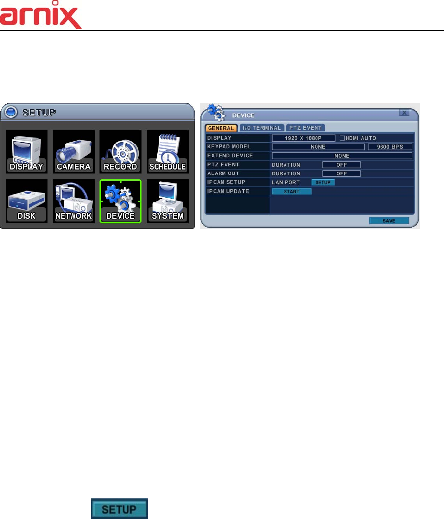
7. DEVICE
7.1. GENERAL
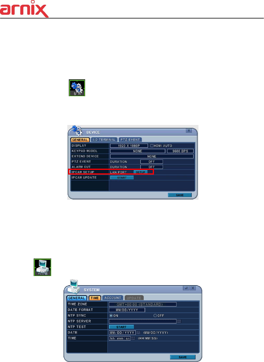
1) DISPLAY : Please decide output video resolution
It can be set to the correct video resolution on the monitor.
[1920*1080P (default) 800*600 1024*768 1280*720 1280*1024
1600*1200 1680*1050 1920*1080I]
HDMI AUTO
Automatically detects and sets the HDMI resolution on the monitor connected to the
NVR. It might display “no video” if a VGA monitor is not able to support high
resolution.
<NOTE>
In order to connect HDMI and VGA output to use both monitors, please set up
as the lowest resolution without selecting HDMI AUTO.
2) Keypad Model: Select Joystick Controller and Baud Rate.
3) Extend Device: Select a model of POS/ATM.
4) PTZ Event: BHA-WC100 Model does not support this feature.
5) Alarm Out: DURATON [OFF,1SEC ~ 5 SEC]: Select Alarm duration.
6) IP CAM SET UP :
After click in the menu, all IP cameras which are connected in LAN
network will be listed in the IP CAM Discovery menu.
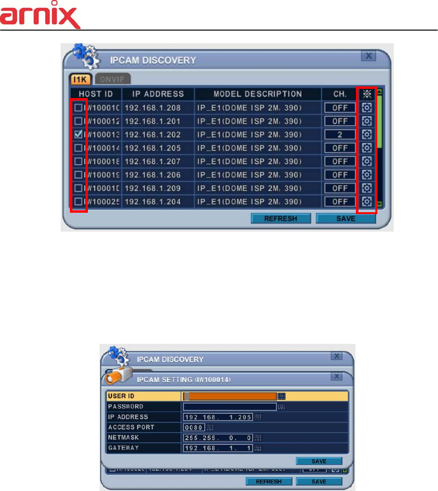
64
A. HOST ID : It shows HOST ID of IP camera.
Please check IP camera which user want to see in monitor.
B. IP : It shows current IP address of IP camera.
C. MODEL : It shows type of IP camera.
D. CHANNEL : User can assign channel and set up information about ID, PASSWORD
and network setting.
Note. Even though ID and PASSWORD is incorrect, it shows in live monitor.
But user cannot change IP camera’s setting in camera menu.
2. Save changes and exit the menu, press the [MENU] button.
Exit the menu without making change, press the [ESC] button.
7.2. I/O Terminal
This NVR supports 4 Alarm Inputs and 1 x Relay Outputs.
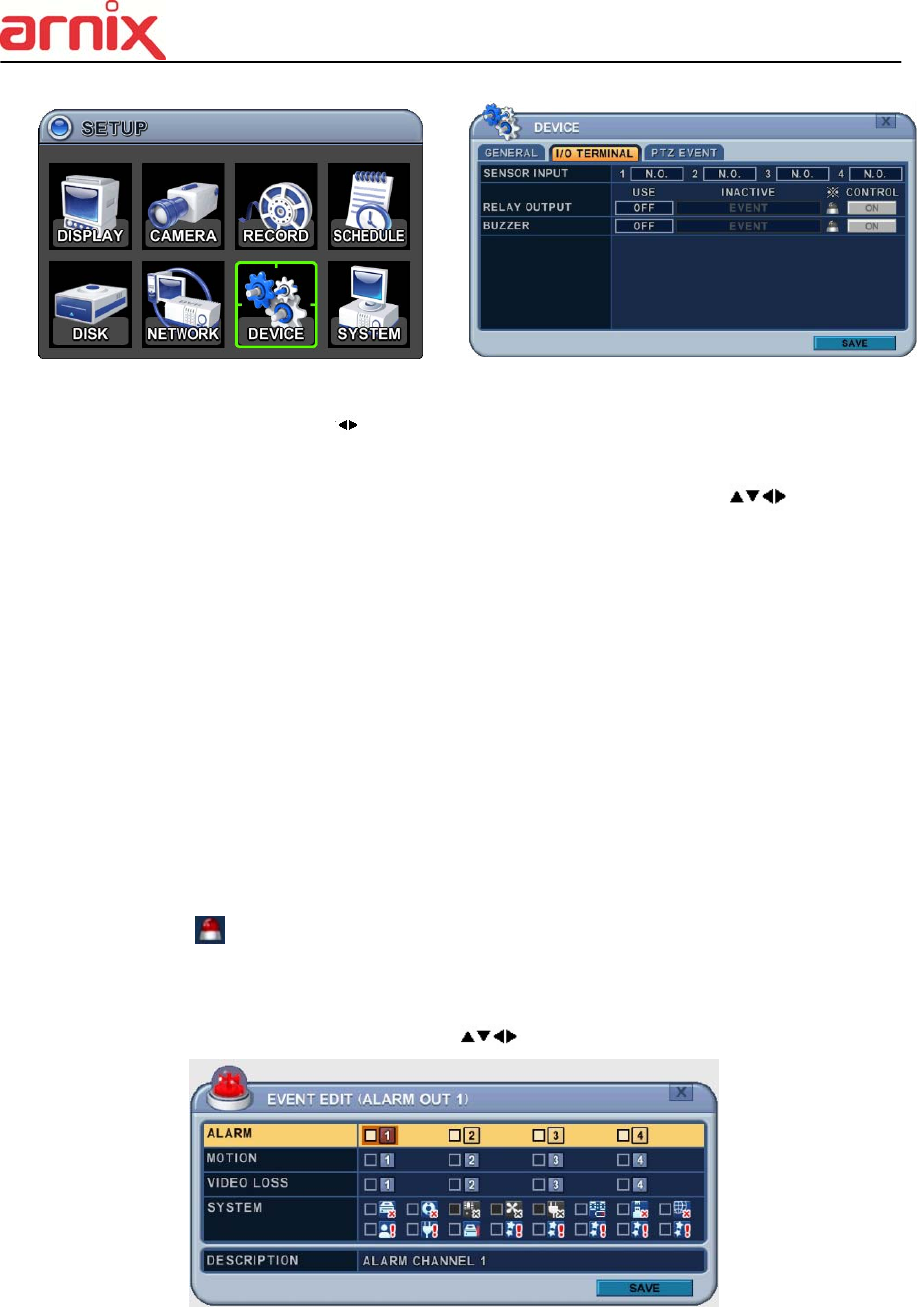
65
2. Use the Left/Right buttons [ ] to select “I/O Terminal” menu tab. The menus are
displayed with options in the left-hand column and settings in the right hand column. A
cursor (highlighted menu) can be moved using the directional buttons [ ].
3. SENSOR INPUT: Change the input type. Use the [-, +] buttons to change the values.
Note. Alarm of IP camera can be configured in CAMERA menu (Chapter 2.2)
4. RELAY OUTPUT: you can configure how the Relay Outputs are controlled: automatic or
manual.
1) Use: Change the output type.
2) Inactive: Select turn off method of Relay Out.
a. Event (Automatic): Relay Out is turned OFF when the event expires. This setting
is configured globally.
b. Manual: Relay Out is turned OFF from this menu <Control>.
3) Event Edit
- Press [OK] to edit multiple events. The menus are displayed with options in the left-
hand column and settings in the right hand column. A cursor (highlighted menu) can
be moved using the directional buttons [ ] on the IR remote or front panel.
- Change the options below using the [DEC/INC] buttons on the IR remote, or click the
mouse.
- System menu contains below

66
1. HDD Disk Fail
2. Record System Fail
3. Temperature Warning.
4. Fan Lock Warning
5. Voltage Warning
6. Low RTC Battery Warning
7. External Device Event
8. Network Link Disconnected
9. Admin Login
10. Power Recovery
11. Disk Full
12. Invalid Password in Sequence
13. Auxiliary Event (Reserved )
4) Control: Manual stops for relay output and buzzer.
5. Buzzer
1) USE
ON: The Buzzer sounds if an alarm is triggered. The buzzer sounds for the duration of the
RECORD TIME. This buzzer relates to Alarm Out. Configure Alarm Out to “ON” for Alarm
Buzzer.
OFF: Disables the ALARM BUZZER function.
2) Inactive: Select turn OFF Buzzer
a. Event (Automatic): Buzzer is turned OFF when the event time expires.
b. Manual: Buzzer is turned OFF from this menu <Control>.
5. Save changes and exit the menu, press the [MENU] button.
Exit the menu without making changes, press the [ESC] button.
7.3. PTZ EVENT (BHA-WC100 Model does not support this feature)
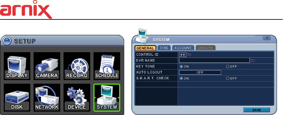
8. SYSTEM
8.1. GENERAL
67
1. Control ID: Each NVR that is preconfigured with the control ID is enabled to respond
to, and be operated by, the remote control.
- To select the NVR to be controlled with the remote controller, press and hold the NVR
ID button. While holding the NVR ID button, press the appropriate NVR ID number.
For example, enter 05 for NVR ID 05, enter 43 for NVR ID 43 etc. Set the ID of IR
controller on “00” to control multiple NVR’s at the same time, whatever the NVR ID is.
2. Device Name: Type a NVR name to distinguish its location when you have several
NVR’s on a Network.
3. KEY TONE: By default, the NVR emits a beep every time a button is pressed. Set the
key tone to OFF to turn the button beep off. By default it’s “ON”
4. AUTO LOGOUT: You can configure the NVR to automatically log users out.
By default it’s “OFF”. [OFF 1 Minute 3 Minute 5 Minute 10 Minute]
5. S.M.A.R.T. CHECK: Turn ON or OFF to display HDD information in the SMART
STATUS tab of the DISK menu.
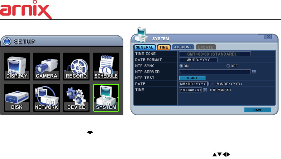
8.2. TIME
Make sure to set up your Date and Time before starting to Record.
68
1. Use Left/Right buttons [ ] to select on “Time” menu tab. The menus are displayed with
options in the left-hand column and settings in the right hand column. A cursor
(highlighted menu) can be moved using the directional buttons [ ]. Press the [-,
+] buttons to change the values.
1) Time Zone: Refer to <Appendix 1: Time Zone Chart>
Selects the time zone where the NVR is located. Time Zone contains DST (Daylight
Saving Time) ON. If you choose Time Zone with DST, there is no change in the
system time stamp for recorded data. When the Daylight Saving End date and time
occurs the NVR’s time goes back one hour.
2) Date Format: Select Date display format.
[ MM/DD/YYYY DD/MM/YYYY YYYY/MM/DD ]
3) NTP SYNC: The internal time of NVR can be synchronized with an external time
source using NTP (Network Time Server) Configuration. If the NTP option is ON, the
DATE and Time option is inactivate.
4) NTP Server: Allows you to use a public or private NTP server. Enter the IP address
of the server or domain. The default setting is public “pool.ntp.org”.
<Note> Time Sync. Interval: Min 64 sec. Max 1024 sec.
5) NTP TEST: Test whether NTP Server works or fails.
6) Date & Time: Set current time and date.
2. Save changes and exit the menu, press the [MENU] button.
Exit the menu without making changes, press the [ESC] button.
69
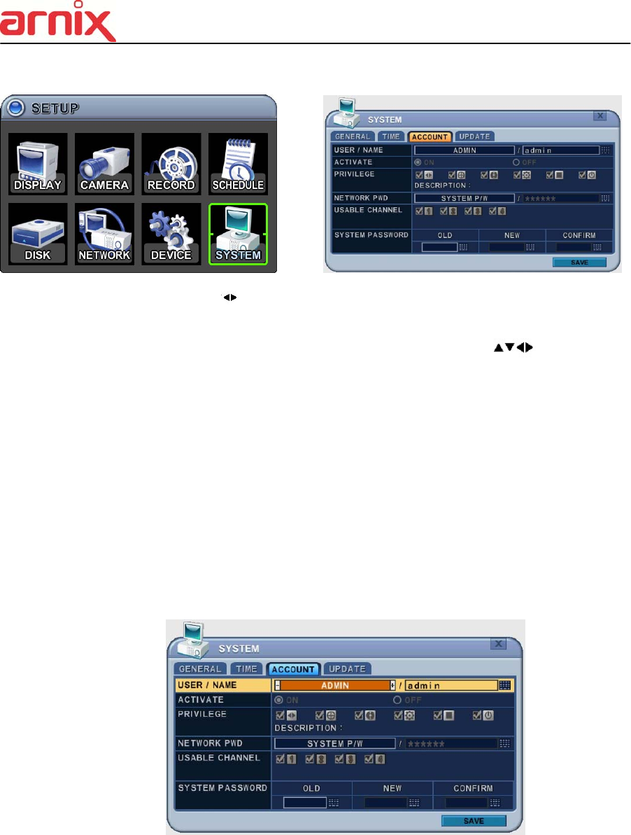
8.3. ACCOUNT
.
1. Use the Left/Right buttons [ ] to select “Account” menu tab. The menus are displayed
with options in the left-hand column and settings in the right hand column. A cursor
(highlighted menu) can be moved using the directional buttons [ ]. Press [-, +]
buttons to change the values.
1) User/Name: The NVR comes preconfigured with ADMIN. Select a User 1~10, and
then activate it by setting to ON.
a. Name Length: up to 10 characters.
b. Characters: A to Z, numerals 0 to 9.
2) Privilege: Admin can define each user’s Privilege, such as PLAYBACK, PTZ
CONTROL, BACKUP, CONFIGURATION (except for Disk and System), RECORD
STOP, and SYSTEM SHUTDOWN.
3) Network PASSWORD: The NVR comes preconfigured with a System Password for
Network access for Admin and/or Deny for User. It is possible to create different
passwords for Network access; choose using [Custom P/W].
a. Password Length: up to 14characters.
b. Characters: A to Z, numerals 0 to 9.
70
4) Usable Channel
Allow each user different live channels for monitoring.
5) Password
Enter the 6 characters for the new password, and then re-enter the same password
under the COMFIRM section. An asterisk is displayed for each character entered.
2. Save changes and exit the menu, press the [MENU] button.
Exit the menu without making changes, press the [ESC] button.
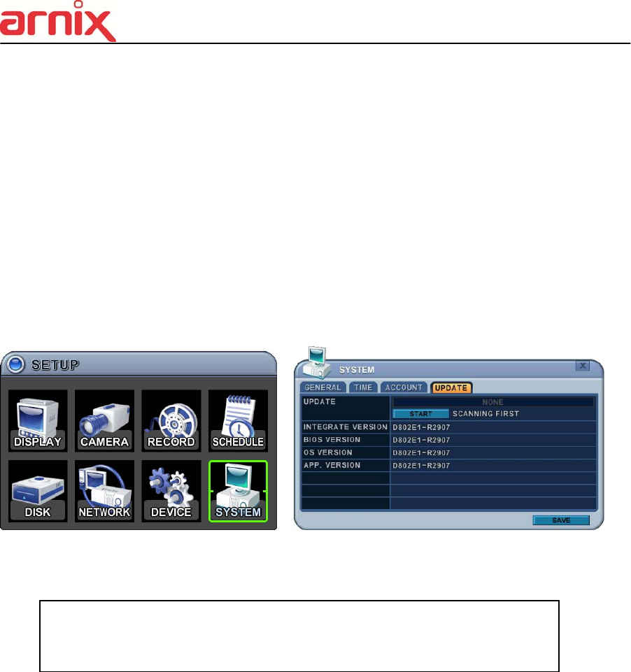
8.4. UPDATE
1. Download the latest firmware file and copy to USB Flash memory stick in the Root
directory.
2. Connect or insert into Front USB (please stop recording first).
3. Use directional buttons to move to the [Start] button. Press the [+] button to find upgrade
files. If the NVR finds a valid upgrade file, the update menu is activated.
4. Press the [-, +] buttons to find correct upgrade file. Version information is displayed. If
there are several valid update files, please check the display for the correct one.
<NOTE > Please make sure you download all of files below (20M).
hd4k_all.00.00.00.img
71
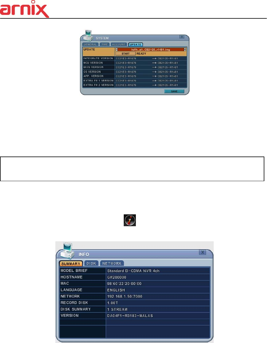
5. Use the directional buttons to move to the [Start] button, then press [OK] button to start
updating. While updating, ”in progress” message is displayed.
6. After the update process is complete, a “Success” message is displayed. Press the [OK]
button to restart.
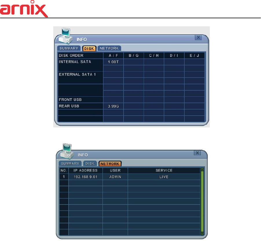
8.5. INFO
Press [info] button on IR remote or select icon on the menu. The system information is
displayed.
SUMMARY : It contains brief model information, Mac Address and installed HDD status
NOTE 1 Do not switch OFF or PRESS any key during the update process.
NOTE 2 Please consult
y
our distributor or installe
r
before u
p
date this.
72
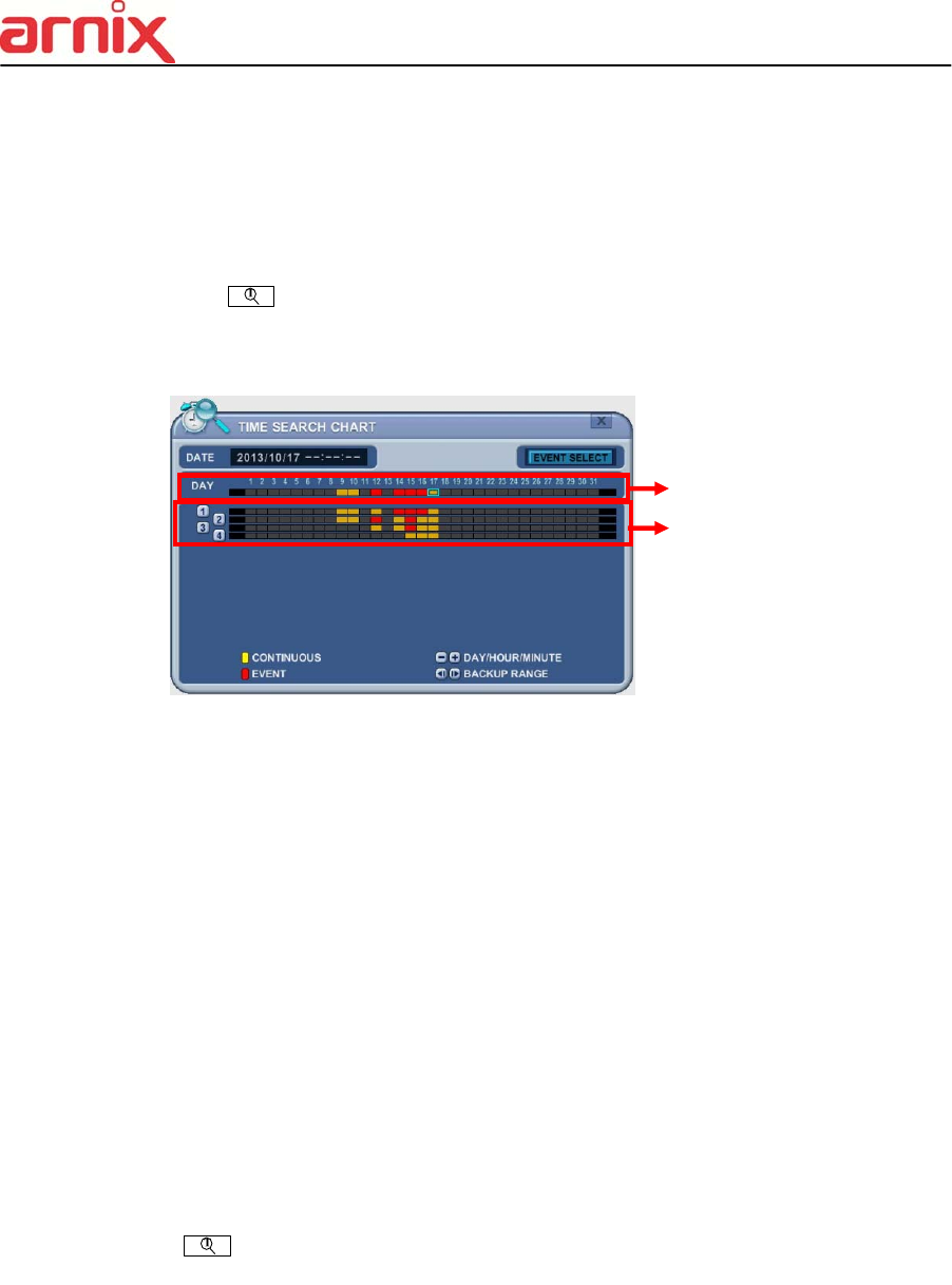
DISK : It contains all DISK information including internal & external HDDs and USB memory.
NETWORK : It shows IP address, USER and service of NET user.
VI. PLAYBACK /SEARCH
The NVR supports 2 playback modes; Playback and Search. The NVR offers a variety of
search functions that enable you to quickly and efficiently locate and review a specific period
from the database. It supports three different search modes: Date/Time, Event, Event Area
and Log Search.
1. Playback
When the [PLAY] button is pressed, the NVR starts to play back any recorded data from
the latest data, whether in live or recording mode. When the NVR reaches the end of
the recorded data, it stops the playback.
During the playback, the NVR may be played back in reverse, paused, speed search up
73
to 16 times the normal speed, or move through picture by picture.
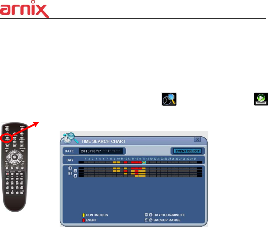
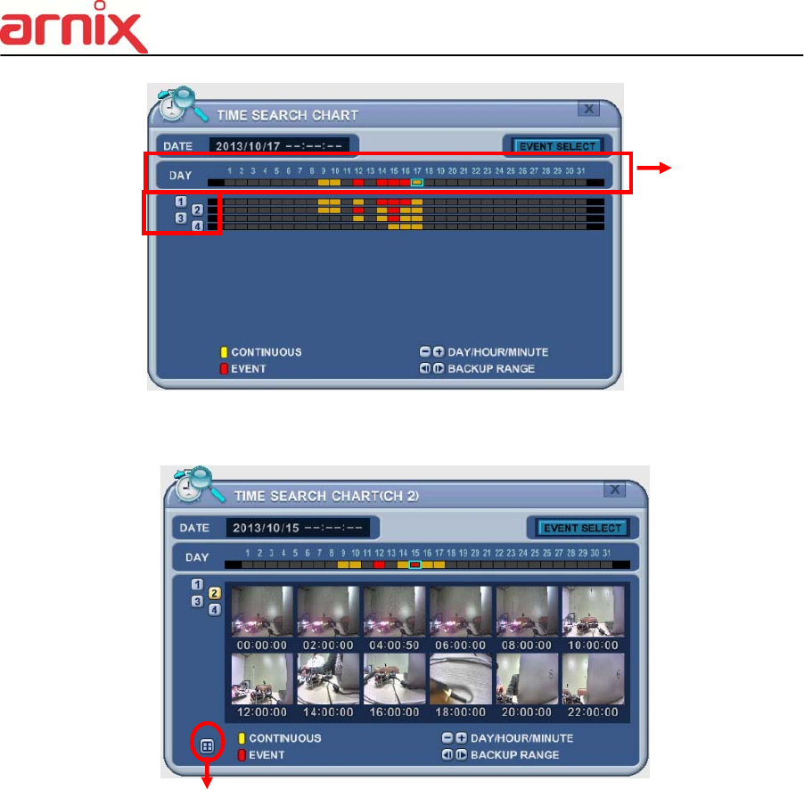
2. Time Search
2.1 Multi Channel Playback
1. Press the [Time Search] button to access the time search table. Day will
be displayed. The data is color-coded by category: EVENT (Red) > Normal
(Yellow)
2. Use the [+] button to navigate to the desired DayHourMinute (5min)
Minute (30 sec). Use the [-] button to go back minute (30sec) Minute (5min)
HourDay.
When using the mouse, the wheel is used for the [+/-] button.
<Note> Use the [Play] button to move to the end of data
Use the [Rewind] or [Fast-forward] buttons to move to the next page.
3. To review all channels, press the [OK] button on the slot on the bar. When using
the mouse, double click.
4. The NVR starts the playback mode, displaying all channels. Any channel
number or the DISPLAY button may be pressed to change the display mode.
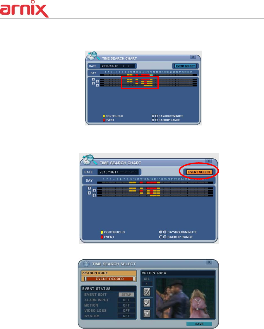
2.2 Preview Search (Single Channel Playback)
The NVR allows you to quickly review a single channel of playback over a period of Day,
Hour, and Minute.
1. Press the [Time Search] button to access the time search table. Day will be
displayed.
Day, Hour, Minute
Channel
74
2. Choose the desired channel to review by pressing a numeric button or Click Channel
number on the left.
Click to return (to chart)
3. Use the [+] button to navigate to the desired DayHourMinute (5min) Minute
(30sec). Use the [-] button to go back minute (30sec) Minute (5min) HourDay.
When using the mouse, the wheel is used for [+/-] button.
4. While reviewing snapshot, use numeric buttons to review other channel.
5. Use the directional button to select snapshot and, press the [OK] button. Using mouse,
double click.
6. The NVR starts the playback mode, displaying the selected channel. Any channel
number, or the DISPLAY button, can be pressed to change the display mode.
2.3 Event Record Search
Event Record search feature allows you to search for recorded video by event.
The time search table displays time events. As a default, the TIME SEARCH
CHART displays CONTINUOUS recording (Yellow) and EVENT recording (Red).
Channel
Day, Hour, Minute
75
TIME SEARCH CHART displays different outcomes according to the SEARCH
MODE below.
[FIGURE 1]
1. Press the “Event Select “button to change search mode.
2. Press [OK] to set up. Press [+/-] button to select “event record”.
3. Press [+/-] button to select “SEARCH MODE “(Event Source /Motion Area).
By selecting Search Mode, TIME SEARCH CHART displays different outcomes.
<Note> EVENT RECORD is set by default and makes the TIME SEARCH
CHART display EVENT recording in Red as above FIGURE 1.
2.4 Event Source Search
Event source search feature allows you to search the recording data for ALARM,
MOTION and VLOSS events previously triggered on the NVR.
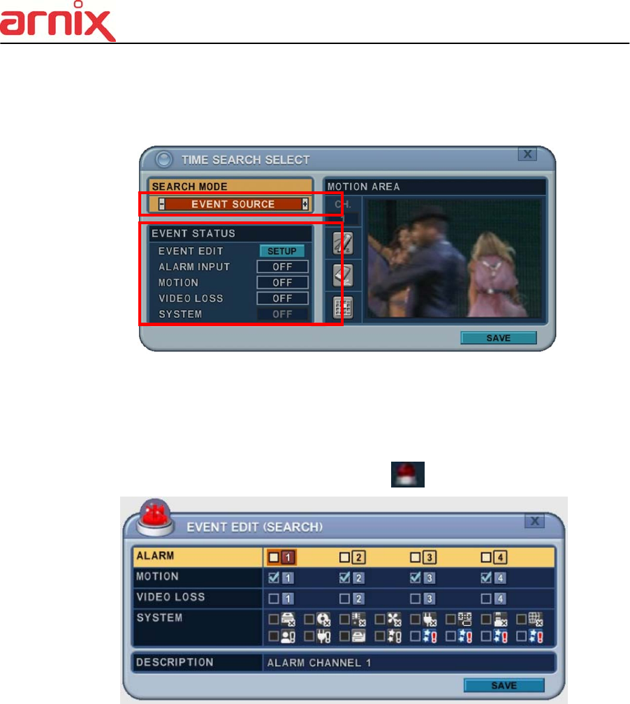
76
1. Press [+/-] button to select “Event Source” in search mode.
And select the event source (Alarm, Motion, Vloss) which you want to search.
1) ALARM: Select Alarm Input 1~4.
2) MOTION: Select the channel 1~16.
3) VLOSS (Video Loss): Select the channel 1~16.
4) SYSTEM: Inactivated
2. Users can have multiple selections by pressing icon, as shown below.
2.5 Motion Area Search (Single Channel Playback)
The NVR searches for recorded video that matches the search area defined by selected
cells.
1. Select “MOTION AREA” (single channel playback) to search the recording data that
has motion in a specific area on a certain channel.
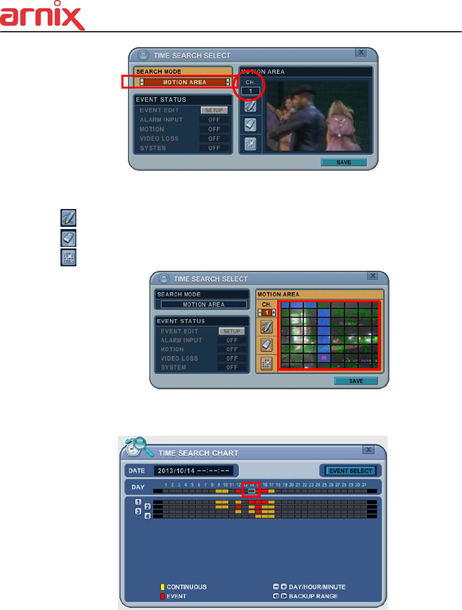
77
2. Press the [+/-] button to select the channel you want to search.
3. Select the motion area you want to search.
: Select all grids
: Deselect all grids
: Select grids, one by one, by pressing the [+/-] button
4. Press the MENU button and the TIME SEARCH CHART displays recording data, in
red, to show what’s happened on that channel.
3. Go to Search
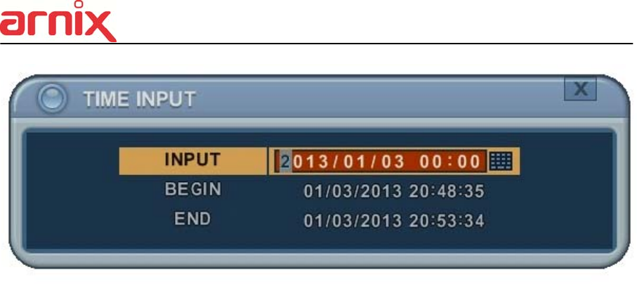
78
1. Press the [Time Search] button for 2 second and the [Time Input] menu pops up.
2. Set the date and time you wish to search.
3. Press [OK] or [Menu] to start searching.
4. Log List Search
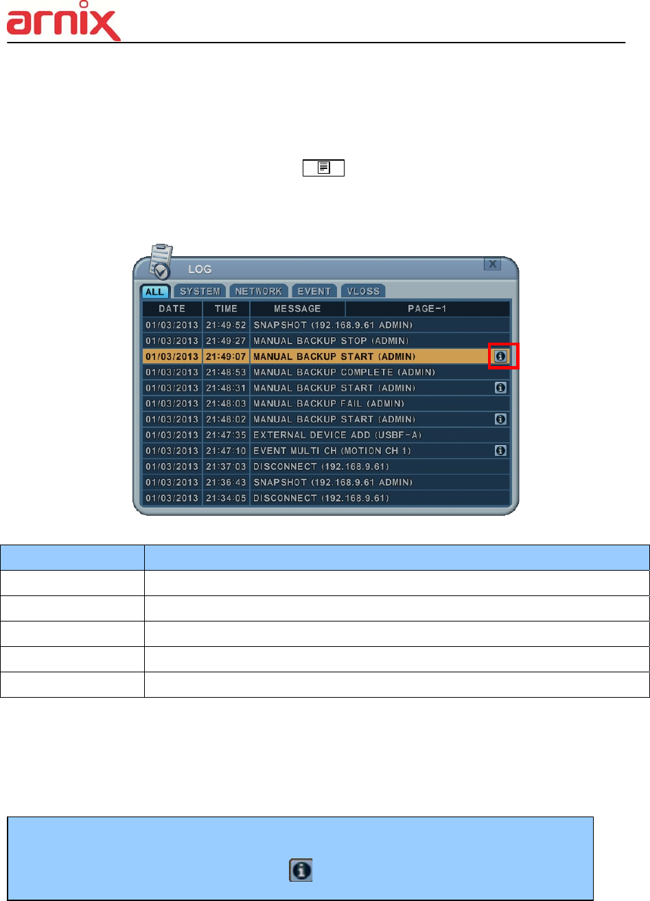
79
The logs can be used to search, and to review, any point in time of the recorded data.
Alarm, Motion, Video Loss and system related logs can be searched and played back directly
from the time of the incident.
1. To start an Event Search, press the [Log] button on the IR Remote and the
Log List Menu pops up, as shown below.
2. Use the Up/Down buttons [] to the desired “Time” to playback. Use the Left/Right
buttons [] to move to the NEXT page.
3. Press the [OK] button to start playback.
MENU TAB CONDITION
ALL A list of all events since the initial NVR power on procedure.
SYSTEM Shows the System List.
NETWORK Shows the NETWORK List.
EVENT Shows the Events List.
VIDEO LOSS Shows Video Loss List.
<Note> 1) Log list is saved on HDD.
2) For more detailed information press
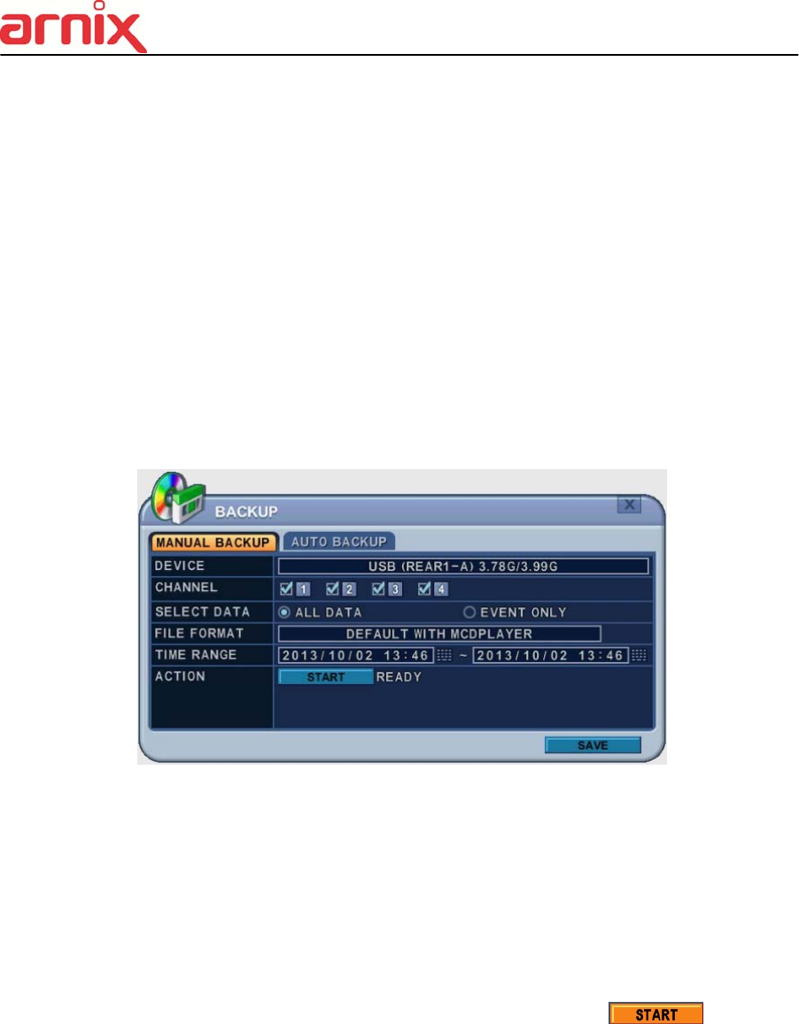
80
VII. BACKUP
1. Manual Back Up
1.1 External DVD- R/W
14. External USB-HDD, CD/DVD-RW is recognized within 10 seconds after plug in UBS
connection cable to UBS port in DVR.
1. Plug in USB connector into the USB connection port on the front panel.
2. Press [BACKUP] button to display the backup menu.
1. Use the [-, +] buttons to change device selection: USB CD/DVD RW
2. Use the [-, +] button to select a channel. All channels are set by default.
3. Select the data for BACKUP.
(1) ALL Data: Normal Recording Data
(2) Event Only: Event Recording Data.
4. File format when saving is “.s” AVI is not supported for CD/DVD
5. Select the time range starting time and ending time.
6. Enter the numbers as required in 24-hour format, then move to .
7. Press the [+] button to start BACKUP..
15. The progress of the backup is displayed at the bottom of the window as a percentage of
the entire backup process. The OSD disappears by pressing cancel button. However,
pressing the Backup button again will show the Backup status. It is recommended that
playback is not performed while the NVR is in a backup session..
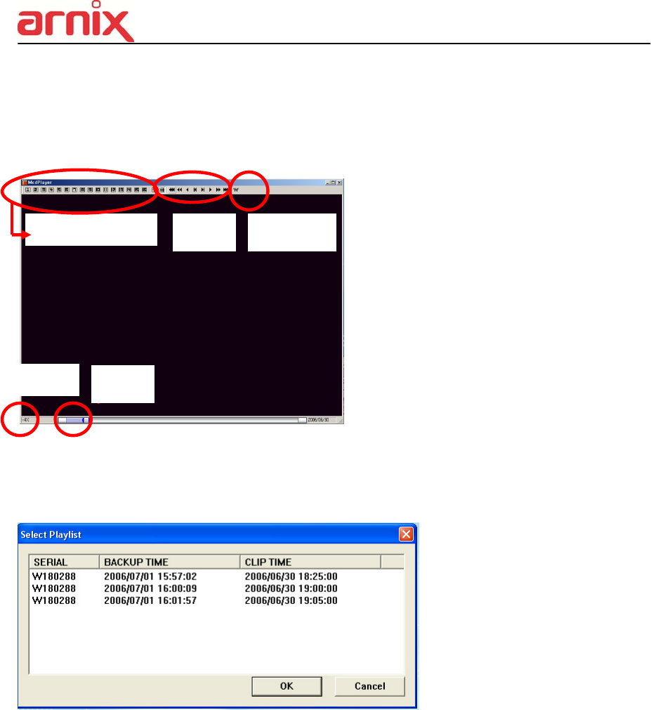
81
8. When finished, the media is ejected.
16. If there is not enough space on the media the NVR automatically ejects the disk when
it’s full and resume the process once new media is inserted into the drive.
* The CD Playback software will simply “auto-
run” and does not require any software
installation on your PC.
<Note> Please Refer to [LOCAL PLAYER] section to read about back-up devices.
<Note 2> When you back up as Multi-Section the Play List pops up instead of Auto Run.
Channel Select FF/FR Watermark
Play
Stop
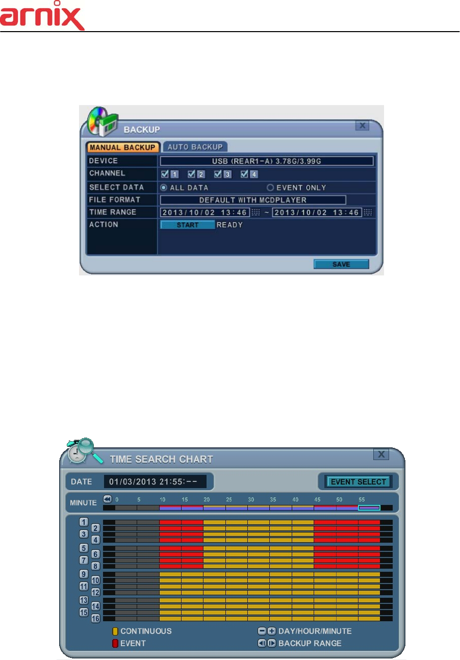
82
1.2 External USB HDD/ Memory Stick
The external drive procedure is the same as using the internal CD/DVD-RW for backup.
To read USB backup HDD in Window, format to FAT32 or NTFS.
To backup as an AVI File, set the file format to AVI using the [+] button.
1.3 Back up Range Setup
Press the [◄▌] button to set backup start time and press the [▐►] button to set the end.
Selected time changes to a Violet color.
Selected backup time is displayed on the backup range.
[LOG IN/OUT] button is toggled for the range.
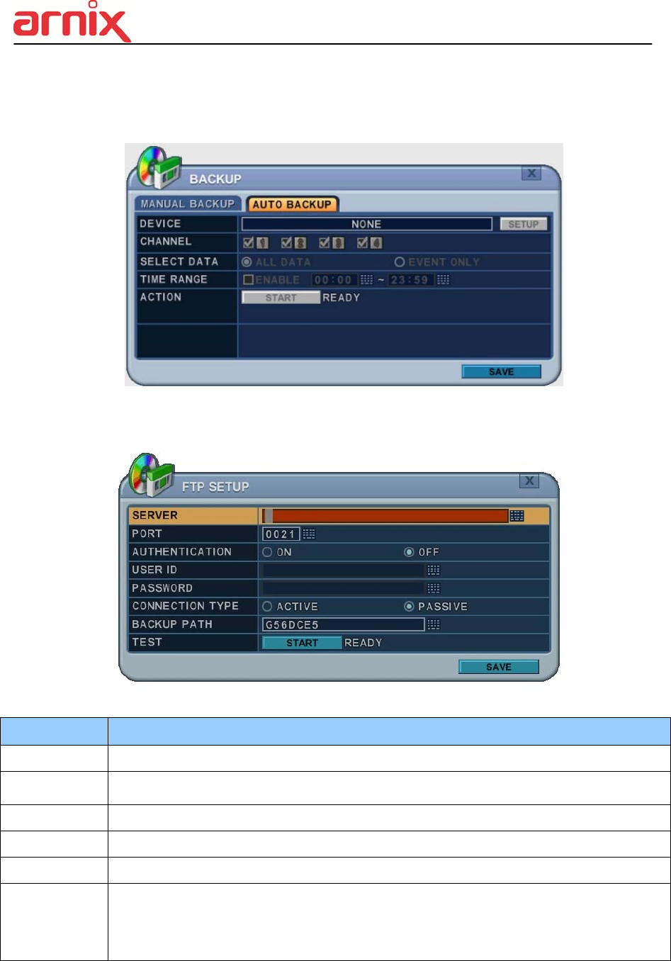
83
2. Auto Back Up (FTP)
1. Use the [-, +] button to change the selected device to FTP
2. Use the directional buttons to move to FTP Setup. The menus are displayed with options
in the left-hand column and settings in the right hand column.
<Note> Please Refer to [LOCAL PLAYER]/ [Mini-Player] section to read about back-up file
ITEM ADJUSTMENT
Server Select Highlight FTP Server and then press numeric buttons to define an FTP server.
Port Define the port that the FTP server will communicate through.
User ID Enter the user ID of FTP Server.
Password Enter the password.
Connection Select PASSIVE mode or REGULAR Mode.
BACKUP
PATH
The path should be made in the FTP server in advance. Mac address is set with the
default in consideration of the scenario where lots of NVR’s backup files to the same
FTP server.
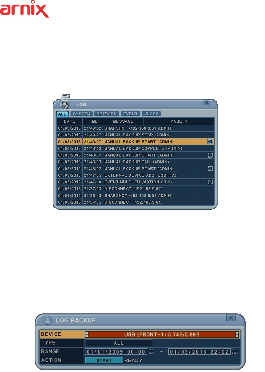
84
3. Log List Back Up
1. Plug the USB memory stick into the USB port.
2. Press the “Log” button to see the NVR Log List.
( Click Log icon on the upper left by mouse)
3. Press the “back up” button to save the log list to USB memory stick.
1) Use the [-, +] buttons to select a device.
2) Select type of Log List from ALL, SYSTEM, NETWORK, EVENT and VLOSS.
3) Select the time range - start and end time.
4) Press the [+] button to start the BACKUP.
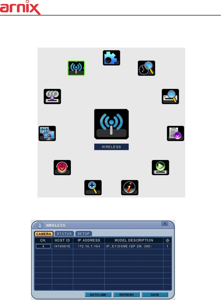
85
VIII. WIRELESS
1. CAMERA
1.1 List
- The list shows the IP Cameras that are currently connected to NVR wireless module.
1) Channel : User can change the channels by using [-, +] button.
2) HOST ID: Shows IP Camera’s name.
3) IP Address: Shows IP Camera’s IP address
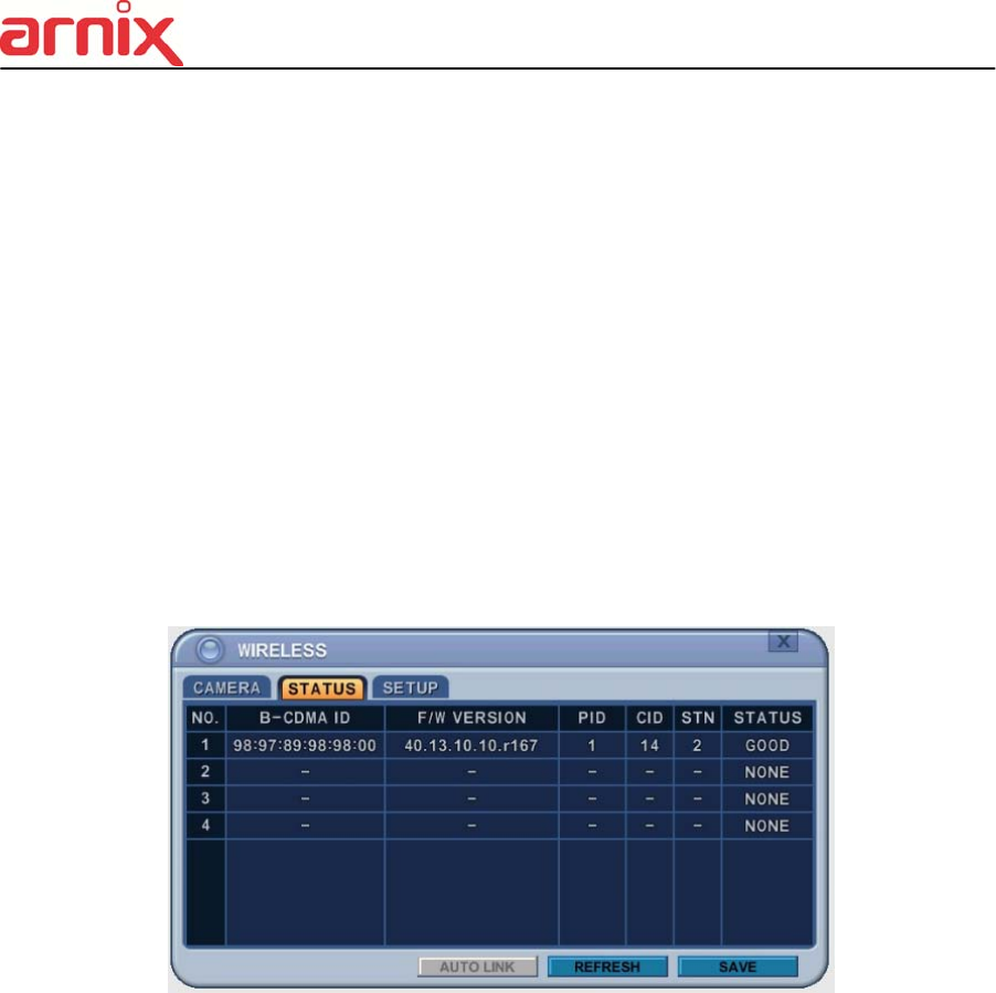
86
4) Model Description: Shows the description on the IP Camera.
5) ※ : Shows the wireless module number of the NVR
1.2 Auto Link
1) Use Up/Down [] buttons and Left/Right [] buttons to select Auto Link
2) Automatically connects the IP Cameras to unoccupied channels.
1.3 Refresh
1) Use Up/Down [] buttons and Left/Right [] buttons to select refresh
2) Automatically refreshes to scan for IP Cameras that are connected to the wireless
network.
2. STATUS
2.1 List
- Shows the current status of the wireless module on the NVR.
1) B-CDMA ID : Shows ID of the wireless module on NVR.
2) F/W VERSION : Shows the firmware’s version of the wireless module on NVR.
3) PID : Shows ID used to wirelessly communicate on the PICONET.
- PICONET ID must be matched between IP Cameras and NVR in order to establish
wireless connection.
4) CID : Shows the connected frequency channel.
- 2.4GH : Channel 0~4
- 5.8GH : Channel 12~19
5) STN : Shows the connected numbers of NVRs and IP Cameras.
- STN = NVR(1ea) + IP Cameras
6) Status: Shows the current status of the wireless module on the NVR.
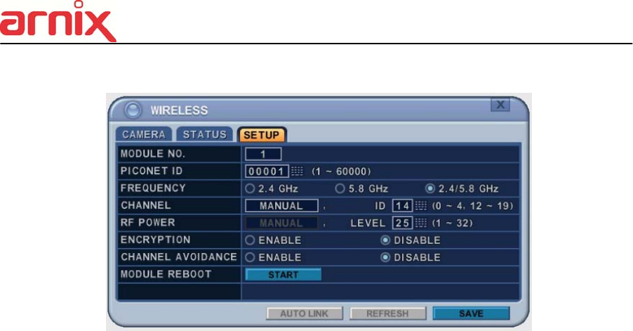
87
3. SETUP
1) MODULE NO : User can change the module by using [-, +] button.
2) PICONET ID : User can change the ID by using [-, +] button.
- This ID is used for establishing wireless connection and it is chageable. But the ID
must match IP Camera’s ID in order to establishing the succesful wireless connection.
3) FREQUENCY : Selectable from 2.4GHz, 5.8GHz, and 2.4/5.8GHz.
4) Channel : Selectable from AUTO, MANUAL
- AUTO : Automatically allocated to the channels.
- MANUAL : Manually allocated to the channels.
5) RF POWER : User can set the RF power of the module.
- Low power settings are suggested when the distance from IP Camera to NVR is
close and High power settings are suggested when the distance from IP Camera to
NVR is far.
6) ENCRYPTION : User can choose whether the wireless signal transmission will use
encryption feature or not. Enabling this feature may decrease the wireless transmission
rate by a little.
7) CHANNEL AVOIDANCE : User can choose whether the wireless signal transmission will use
channel avoidance feature or not.
- If the channel setting is on “Manual”, this feature will not be enabled.
8) MODULE REBOOT : NVR forces the wireless module to reboot by clicking this button.

88
IX. CLIENT SOFTWARE
All Client S.W is dedicated client program that connects and manages in real time.
Please refer to each S.W manual for more information.
1. Web server: Using Internet Explorer
2. EMS2.0 Lite: Management S.W that allows you to view and manage up to 300 DVRs.
3. iSMS: 1:1 Management S.W for the Mac PC.
4. SMART Phone: Touch CMS Lite for iPhone, Android,

89
X. SPECIFICATION
IP Camera Model Name BHA-WC100
Camera
Image Device SONY 2.1M Pixel 1/2.8” CMOS Sensor
Focal Length Fixed Focal Lens with IR Cut Filter
Horizontal Angel 97.8°
Min. Illumination 1.0 Lux (Color), 0.5 Lux (B/W)
AE Mode Auto / Manual
Shutter Speed Auto / 1/30~1/60000
White Balance Auto / Indoor / Outdoor
Function WDR (Wide Dynamic Range), 3D DNR (Digital Noise Reduction)
Video
Compression H.264 High Profile, MJPEG
Streaming
Triple: Full HD recording, HD Live, SD Live
45fps (Max)
Resolution Full HD (1920x1080) HD( 1280x720), SD (720x480, 720x576)
Max. Frame Rate 30fps (NTSC), 25fps (PAL)
Audio
Compression PCM Coding
MIC/Speaker MIC In / Speaker Out
Sampling 8 KHz
Network
Ethernet Ethernet 10/100 Base-T (RJ-45)
Wireless ISO/IEC 24771 Koinonia Binary CDMA Compliant
IP IPv4
Protocol
HTTP, FTP, SMTP, DNS, DynDNS, NTP, RTSP, RTP, TCP, UDP,
ARP, DHCP
Alarm
/ Event
Motion Detection
Selected 4 Zone
Alarm Trigger
Event (Alarm, Motion Detection), Video Loss
Alarm Notice
Send capture image by E-mail,
Save capture image to Micro SD Card and FTP server
Function
Viewer OS
All Use: Internet Explorer (32bit), Android, iOS
Setting Only: Firefox, Safari, Chrome
Firmware Web Update
General Power Supply DC 12V / 1.5A
Dimensions 132mm (L) x 40mm (W) x 66mm (H)

90
NVR Model Name BHA-WN400
Video
Input 4Ch (D1, 720p, 1080p)
Output VGA / HDMI (up to 1920x1080p)
Recording
Compression H.264 High Profile
Maximum Rate &
Resolution
NTSC 120fps@D1, 720p, 1080p
PAL 100fps@D1, 720p, 1080p
Recording Quality Grade Ultra, Super, High, Middle, Low (5 levels)
Recording Mode Continuous, Schedule, Event(Motion, Alarm), Video Loss
Pre/Post Recording Up to 5 sec / Up to 300sec
Watermark Proof Yes
Playback
Digital Zoom 2x, 4x, 8x
Speed 1x ~16x Fast-forward/Rewind, field by field
Search Mode Calendar, Time, Event, Thumb-nail, Instant Replay
Storage
Interface SATA
Max. Capacity of 1 HDD 3TB
Max. Number of
Internal HDDs
2EA (HDD not included in the package)
S.M.A.R.T. Yes
External Storage e-SATA (1 port), USB (2 port)
Backup Media USB-DVD±RW / USB Flash Stick / Network
OSD
Display Division 1, 4 division
Title Multi Language / 12 Characters
Multi Language 22 Languages
Network
Ethernet RJ-45, 10/100/1000M
Wireless ISO/IEC 24771 Koinonia Binary CDMA Compliant
Streaming TCP/UDP
Protocols TCP/IP, SMTP, DHCP, DDNS, uPNP
Network Users 1 Admin + 10 Users
Client Software
EMS, Web Viewer for Windows PC,
iSMS for Mac PC
Touch CMS for 3G Mobile (Android & iOS)
Remote Notification Email, Push Alarm Notification (for Mobile)
System External Port RS-232, RS-485

91
USB Port 2 Ports (Front & Rear)
Control Devices USB Mouse, IR Remote Controller, RS-485 Keypad
Others
Firmware Update USB Flash Stick / Network
Time Setting Time Zone, Daylight Saving, NTP Sync
Power Recovery Function Yes
Log Event log (50,000ea) / System log (20,000ea)
Watchdog Yes (Software / Hardware)
Auto Deletion 12 Hours ~ 30 Days
General Power Supply DC 12V, 5A
Dimensions 220mm (L) x 240mm (W) x 156mm (H)

92
Appendix 1: Time Zone Chart
Standard Time Time Zone
GMT+00:00 Standard
European DST
GMT+01:00 Standard
European DST
Namibia DST
GMT+02:00 Standard
Israel DST
European DST
Lebanon DST
Jordan DST
Russia DST
Egypt DST
GMT+03:00 Standard
Russia DST
GMT+03:30 Iran DST
GMT+04:00 Standard
Azerbaijan DST
Russia DST
GMT+04:30 Standard
GMT+05:00 Pakistan DST
Russia DST
GMT+05:30 Standard
GMT+05:45 Standard
GMT+06:00 Standard
Russia DST
GMT+06:30 Standard
GMT+07:00 Standard
Russia DST
GMT+08:00 Standard
Russia DST
GMT+09:00 Standard
Russia DST
GMT+09:30 Standard
Australia DST
GMT+10:00 Standard
Russia DST
Australia DST
GMT+11:00 Standard
Russia DST
GMT+12:00 Standard
New Zealand DST
GMT+13:00 Standard
GMT-01:00 Standard
European DST
GMT-02:00 Standard
GMT-03:00 Standard
Brazil DST
European DST
Uruguay DST
GMT-04:00 Chile DST
US DST
GMT-04:30 Standard
GMT-05:00 Standard
US DST
GMT-06:00 Standard
Mexico DST
US DST
GMT-07:00 Standard
Mexico DST
US DST
GMT-08:00 Standard
Mexico DST
US DST
GMT-09:00 Standard
US DST
GMT-10:00 Standard
GMT-11:00 Standard

Customer Support
Technical Assistance
If you need assistance installing or troubleshooting your device, please contact us by using one of the
methods below:
Knowledge Base: www.emw.co.kr
Our Knowledge Base provides thousands of immediate solutions. If the Knowledge Base cannot help,
our Technical Support Portal (see below) provides an easy way to report your problem or ask your
question.
Technical Support Portal: www.emw.co.kr
The Technical Support Portal not only allows you to report your problem, but it also provides
immediate solutions to your technical issues by searching our Knowledge Base. With the Portal, you
can submit and track your questions online and send and receive attachments.
Web Form: www.emw.co.kr
You can contact our technical support team directly by filling out our online support form. Enter your
contact details and the description of the question/problem.
Telephone: www.emw.co.kr
For our latest contact information, please check our website at the link above.
Product Service and Repair
EMW Co., Ltd. provides service for all of its products through service centers throughout the world. To
obtain warranty or non-warranty service, please visit www.emw.co.kr and select Support > Contact
Service and Repair to see your region’s instructions on how to obtain a Return Material Authorization
number (RMA #). You should do this prior to returning the product.

<MEMO>