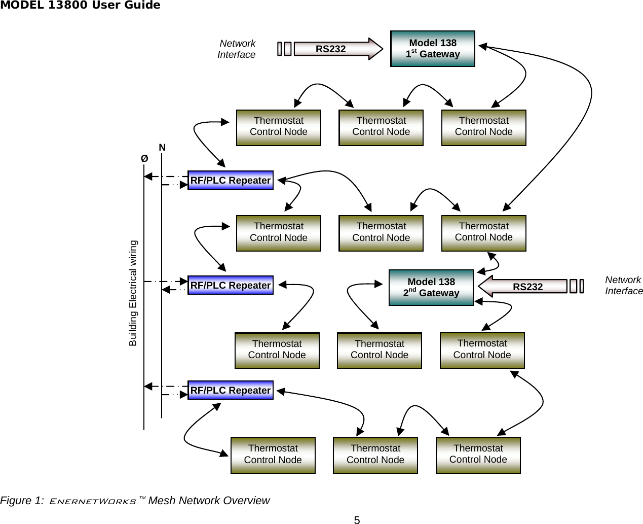
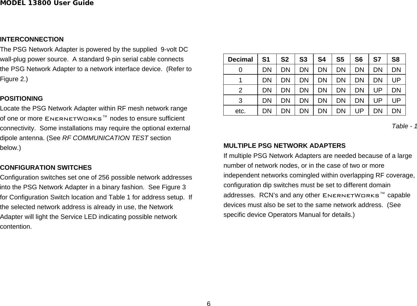
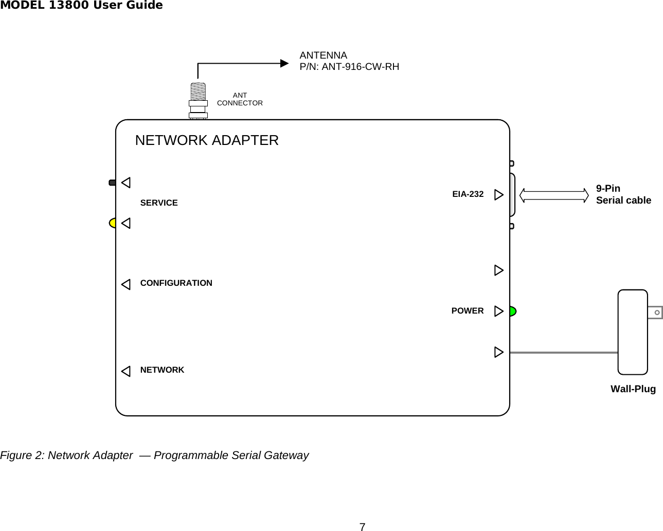
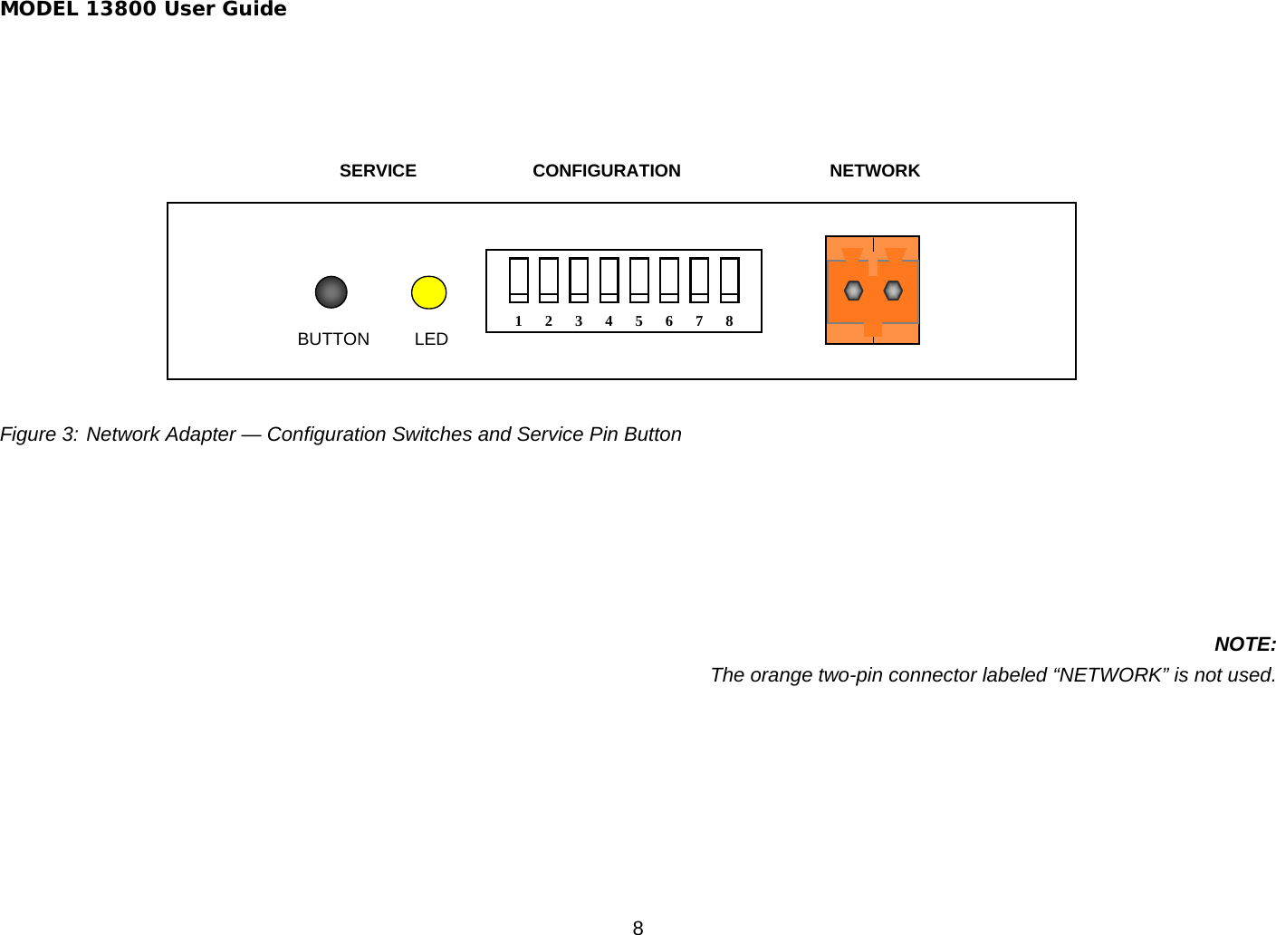
ENERNET 13800 PSG Serial Garteway, P/N 13800 User Manual User Guide rev1
ENERNET Corporation PSG Serial Garteway, P/N 13800 User Guide rev1
UserManual.wiki
>
ENERNET
>
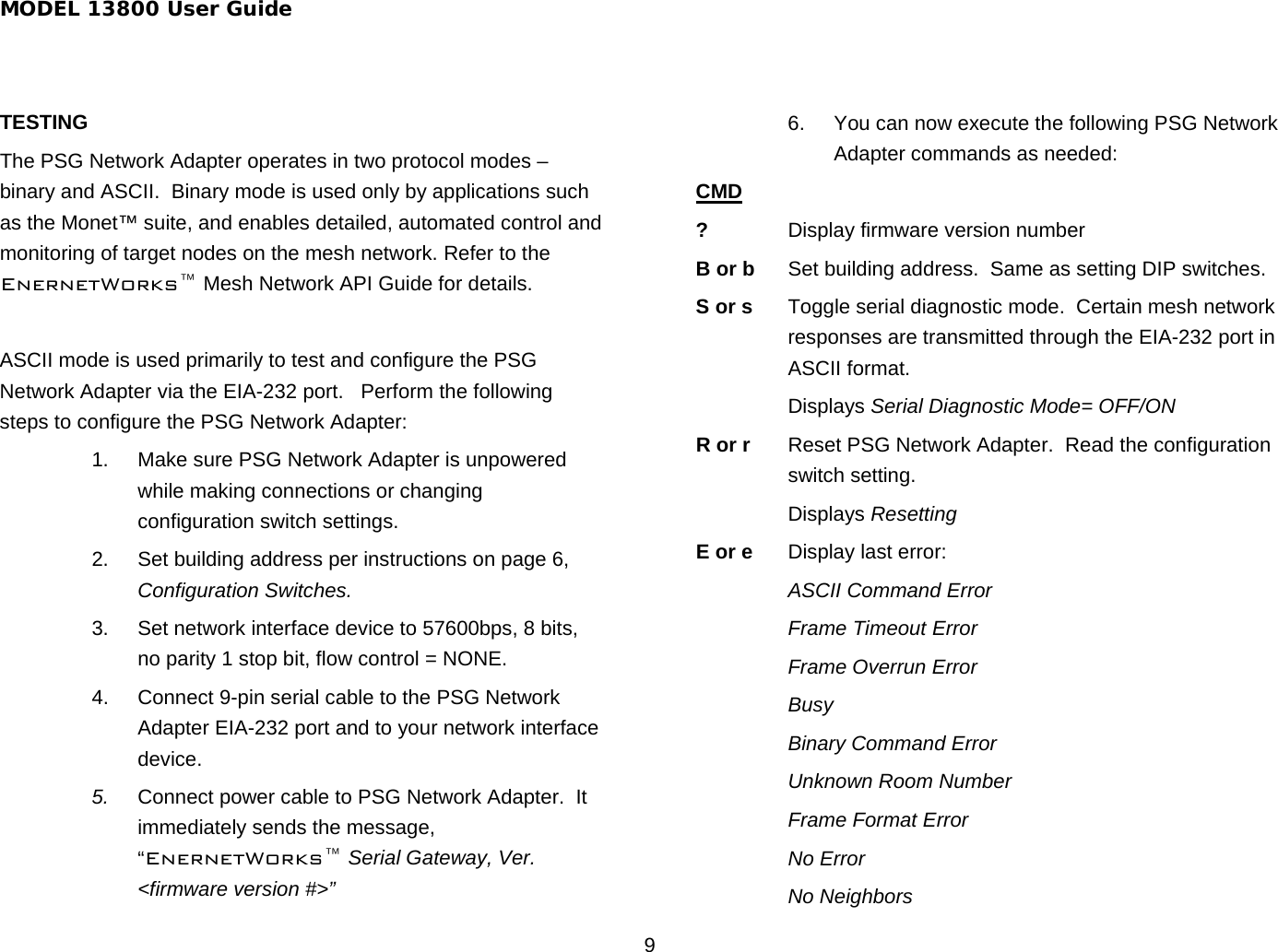
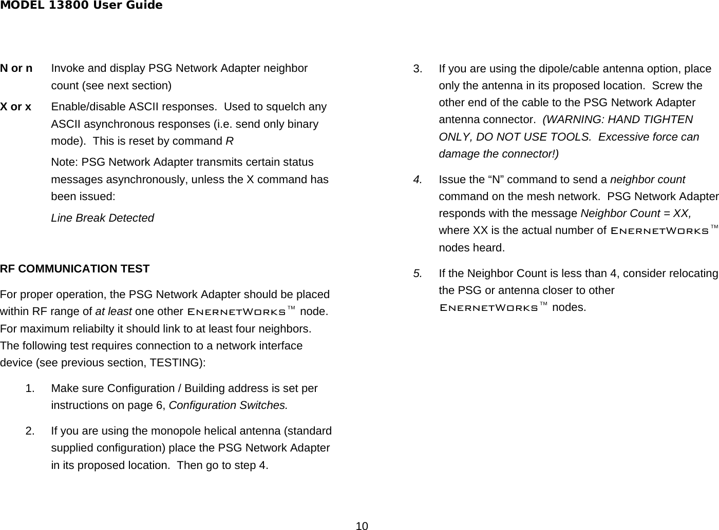
13800 User Manual
User Guide rev1
Navigation menu
Upload a User Manual
Namespaces
Wiki Guide
HTML
PDF
Info
Views
User Manual
Discussion / Help
Navigation