User Manual

Pub No. 15701-091918
ENERNET Corporation Copyright 2018
Model 15700
EnOcean Devices Support Accessory
With
Model 12200C-157
User Guide
MODEL 15700 User Guide
© 2018 ENERNET Corporation • www.enernetcorp.com • 315-449-0839 Pub No. 15701-091918 / Page 2 of 16
FCC PART 15.19 WARNING STATEMENT- (REQUIRED FOR ALL
PART 15 DEVICES)
THIS DEVICE COMPLIES WITH PART 15 OF THE FCC RULES.
OPERATION IS SUBJECT TO THE FOLLOWING TWO
CONDITIONS: (1) THIS DEVICE MAY NOT CAUSE HARMFUL
INTERFERENCE, AND (2) THIS DEVICE MUST ACCEPT ANY
INTERFERENCE RECEIVED, INCLUDING INTERFERENCE THAT
MAY CAUSE UNDESIRED OPERATION.
FCC PART 15.21 WARNING STATEMENT
NOTE: THE GRANTEE IS NOT RESPONSIBLE FOR ANY
CHANGES OR MODIFICATIONS NOT EXPRESSLY APPROVED BY
THE PARTY RESPONSIBLE FOR COMPLIANCE. SUCH
MODIFICATIONS COULD VOID THE USER’S AUTHORITY TO
OPERATE THE EQUIPMENT.
IC RSS-GEN, SEC 8.4 WARNING STATEMENT- (REQUIRED FOR
LICENSE-EXEMPT DEVICES)
FCC PART 15.105(B) WARNING STATEMENT- (ONLY REQUIRED
FOR 15.109-JBP DEVICES)
NOTE: THIS EQUIPMENT HAS BEEN TESTED AND FOUND TO
COMPLY WITH THE LIMITS FOR A CLASS B DIGITAL DEVICE,
PURSUANT TO PART 15 OF THE FCC RULES. THESE LIMITS ARE
DESIGNED TO PROVIDE REASONABLE PROTECTION AGAINST
HARMFUL INTERFERENCE IN A RESIDENTIAL INSTALLATION.
THIS EQUIPMENT GENERATES USES AND CAN RADIATE RADIO
FREQUENCY ENERGY AND, IF NOT INSTALLED AND USED IN
ACCORDANCE WITH THE INSTRUCTIONS, MAY CAUSE
HARMFUL INTERFERENCE TO RADIO COMMUNICATIONS.
HOWEVER, THERE IS NO GUARANTEE THAT INTERFERENCE
WILL NOT OCCUR IN A PARTICULAR INSTALLATION. IF THIS
EQUIPMENT DOES CAUSE HARMFUL INTERFERENCE TO RADIO
OR TELEVISION RECEPTION, WHICH CAN BE DETERMINED BY
TURNING THE EQUIPMENT OFF AND ON, THE USER IS
ENCOURAGED TO TRY TO CORRECT THE INTERFERENCE BY
ONE OR MORE OF THE FOLLOWING MEASURES:
- REORIENT OR RELOCATE THE RECEIVING ANTENNA.
- INCREASE THE SEPARATION BETWEEN THE EQUIPMENT AND
RECEIVER.
- CONNECT THE EQUIPMENT INTO AN OUTLET ON A CIRCUIT
DIFFERENT FROM THAT TO WHICH THE RECEIVER IS
CONNECTED.
- CONSULT THE DEALER OR AN EXPERIENCED RADIO/TV
TECHNICIAN FOR HELP.
ENGLISH:
THIS DEVICE COMPLIES WITH INDUSTRY CANADA LICENSE-
EXEMPT RSS STANDARD(S). OPERATION IS SUBJECT TO THE
FOLLOWING TWO CONDITIONS: (1) THIS DEVICE MAY NOT
CAUSE INTERFERENCE, AND (2) THIS DEVICE MUST ACCEPT
ANY INTERFERENCE, INCLUDING INTERFERENCE THAT MAY
CAUSE UNDESIRED OPERATION OF THE DEVICE.
FRENCH:
LE PRÉSENT APPAREIL EST CONFORME AUX CNR D'INDUSTRIE
CANADA APPLICABLES AUX APPAREILS RADIO EXEMPTS DE
LICENCE. L'EXPLOITATION EST AUTORISÉE AUX DEUX
CONDITIONS SUIVANTES : (1) L'APPAREIL NE DOIT PAS
PRODUIRE DE BROUILLAGE, ET (2) L'UTILISATEUR DE
L'APPAREIL DOIT ACCEPTER TOUT BROUILLAGE
RADIOÉLECTRIQUE SUBI, MÊME SI LE BROUILLAGE EST
SUSCEPTIBLE D'EN COMPROMETTRE LE FONCTIONNEMENT.
THE ORIGINAL EQUIPMENT MANUFACTURER (OEM) MUST
ENSURE THAT FCC LABELING REQUIREMENTS ARE MET. THIS
INCLUDES A CLEARLY VISIBLE LABEL ON THE OUTSIDE OF THE
FINAL PRODUCT ENCLOSURE THAT DISPLAYS THE FOLLOWING:
CONTAINS FCC ID: TGD15700/IC: 6120A-15700

MODEL 15700 User Guide
© 2018 ENERNET Corporation • www.enernetcorp.com • 315-449-0839 Pub No. 15701-091918 / Page 3 of 16
INTRODUCTION
The 15700 accessory PCB is a bi-directional wireless gateway
device that interconnects EnOcean™ energy-harvesting wireless
sensors (e.g. room temperature, motion detection, door switch) to
a host control node. It includes an EnOcean™ RF transceiver
module for communicating with the sensors. An on-board
supervisory microcontroller IC (Silicon Labs EFM8BB2) manages
wireless transmission and reception, formats data for use by the
host control node and supervises linking and removal of external
sensors to form an interconnected system.
The host control Node (e.g. ENERNET 12200C-157 RCN) is wired
to comfort conditioning appliances in the room/zone and is
attached to the 15700 accessory PCB via ribbon cable. It uses
received sensor data to make zone environment control decisions.
MOUNTING
The 15700 has four 0.156” diameter mounting holes. A locking
PCB support with adhesive base such as Eagle Plastic Devices
561-LAD187 or 561-LAD250 available from Mouser Electronics
1-800-346-6873 www.mouser.com is suggested although other
mounting strategies can be used. See Installation Guidelines later
in this manual.
MODEL 15700 / LINK/UNLINK ENOCEAN SENSOR
A function table in the model 15700 EnOcean Devices Accessory
Support module manages the Learning-in and Learning-out of
select EnOcean set point adjustment temperature display, motion
and door switch sensors. The function table presents five (5)
setup options.
MODEL 15700 SETUP MENU
Page 1: Link/Unlink SR06 (Thermokon)
Page 2: Link/Unlink motion sensor (EOSCU or EOSW)
Page 3: Link/Unlink magnetic door switch (EDWS)
Page 4: Link/Unlink emergency shutdown switch (EDWS)
Page 5: Reset to factory default
Selections are indicated through the flash-count of PB4 LED
(Green) and PB5 LED (Red). PB5 LED flash-count indicates the
Page number in the table that is active. PB4 LED flash-count
indicates the operational function to be done in the selected page.
(Refer to Figure 1 for button and LED locations.)
To enter the Sensor Learn Table, press and hold the PB4 until the
PB4 LED & PB5 LED flash alternately. Pressing PB5 moves
through pages 1 – 5, PB5 LED indicates the page number in the
Table you are currently landed on. PB4 selects the action to be
taken in that page. Upon entering a page, the PB4 LED will by
default flash 3 times indicating the default null setting. (NOTE:
PB4 LED and PB5 LED will flash repeatedly until action is taken.)
When any change is made, i.e. learning or unlearning a sensor or
restoring to factory default, you will automatically exit the Sensor
Learn table. (NOTE: To leave the table without making a change,
press and hold PB4 until LEDs stop flashing.)

MODEL 15700 User Guide
© 2018 ENERNET Corporation • www.enernetcorp.com • 315-449-0839 Pub No. 15701-091918 / Page 4 of 16
TO LEARN-IN AN ENOCEAN DEVICE
1. Hold PB4 until PB4 & PB5 LED’s are flashing.
2. Press PB5 until its LED (Red) is flashing desired page.
3. Press PB4 until its LED (Green) flashes once.
4. Press and quickly release (do not hold at all) the “learn”
button on the EnOcean device. (NOTE: A long button
press could be used to configure parameters of the device
you are learning-in. See device data sheet for more
information.)
5. If the Learn-in process is successful, the green LED lights
for approximately 2 seconds and you automatically exit the
setup menu table. Otherwise the red LED lights for
approximately 2 seconds before exiting the setup menu
table.
TO LEARN-OUT AN ENOCEAN DEVICE
1. Hold PB4 until PB4 & PB5 LED’s are flashing.
2. Press PB5 until its LED (Red) is flashing desired page.
3. Press PB4 until its LED (Green) flashes twice.
4. Press and quickly release (do not hold at all) the “learn”
button on the EnOcean device. (NOTE: A long button press
could be used to configure parameters of the device you
are learning-in. See device data sheet for more
information.)
5. If the Learn-out process was successful, the green LED
lights for approximately 2 seconds and you automatically
exit the setup menu table. Otherwise the red LED lights for
approximately 2 seconds before exiting the setup menu
table.
MODEL15700ENOCEANSENSORLEARNTABLE
PB5LEDPB4LED
PAGESENSORFLASH
COUNT
FLASH
COUNTDESCRIPTION
1LINK/UNLINKSR0611‐31=Learn‐in,2=Learn‐out,3=Null
2LINK/UNLINKMOTIONSENSOR21‐31=Learn‐in,2=Learn‐out,3=Null
3LINK/UNLINKDOORSWITCH31‐31=Learn‐in,2=Learn‐out,3=Null
4LINK/UNLINKWINDOW/EMER
SHUTDOWNSWITCH41‐31=Learn‐in,2=Learn‐out,3=Null
5RESTORETOFACTORY
DEFAULT51‐31=RestoreFactoryDefault,2=N/A,3=Null
MODEL 15700 User Guide
© 2018 ENERNET Corporation • www.enernetcorp.com • 315-449-0839 Pub No. 15701-091918 / Page 5 of 16
SMARTACK DEVICES
An additional step is required when learning-in or out a SmartAck
enabled device such as the Thermokon SR06 room sensor.
LEARN-IN SMARTACK ENABLED DEVICES
1. Hold PB4 until PB4 & PB5 LED’s are flashing.
2. Press PB5 until its LED (Red) is flashing Page 1.
3. Press PB4 until its LED (Green) flashes once.
4. Press PB3 on the Model 12200C board (see Figure 1).
5. Press and quickly release (do not hold at all) the “learn”
button on the EnOcean device. (NOTE: A long button press
could be used to configure parameters of the device you
are learning-in. See device data sheet for more
information.)
6. If the Learn-in process is successful, the green LED4 lights
for approximately 2 seconds and you automatically exit the
setup menu table. Otherwise the red LED4 lights for
approximately 2 seconds before exiting the setup menu
table.
LEARN-OUT SMARTACK ENABLED DEVICES
1. Hold PB4 until PB4 & PB5 LED’s are flashing.
2. Press PB5 until its LED (Red) is flashing Page 1.
3. Press PB4 until its LED (Green) flashes twice.
4. Press PB3 on the Model 12200C board.
5. Press and quickly release (do not hold at all) the “learn”
button on the EnOcean device. (NOTE: A long button
press could be used to configure parameters of the device
you are learning-in. See device data sheet for more
information.)
6. If the Learn-out process is successful, the green LED4
lights for approximately 2 seconds and you automatically
exit the setup menu table. Otherwise the red LED4 lights
for approximately 2 seconds before exiting the setup menu
table.
122C00-157 SETUP MENU
Page 1: Deadband: 1 to 5 — default 2
Page 2: Emergency Shutdown: 1 = Not Installed, *2 = Installed
Page 3: Occupied: 1 = none, 2 = motion only, *3 = Motion + door
Page 4: Setback from 72: 1=0, 2=3, *3=6, 4=9, 5=12, 6=15
Page 5: Unocc delay: *2min, 1hr, 4hr, 8hr, 16hr, 24 hr
Page 6: Power on reset: *1 = go occupied, 2 = go unoccupied
12200C-157 Remote Control Node (RCN)
The ENERNET 12200C Remote Control Node (RCN) hardware
platform runs a number of firmware builds depending on the
control application. Firmware 122C09 Rev. 2.37.0 or higher and
122C09-157 Rev.1.00 or higher supports the Model 15700
EnOcean Devices Support Accessory, with or without SmartAck
enabled. (NOTE: Only the 122C09-157 is discussed in this
manual).
Press and hold the PB3 button 122C09-157 to enter the
Configuration Table (see Figure 1) until PB1 & 2 LED’s flash
alternately. Pressing PB1 moves through pages 1 – 6, PB1 LED
indicates configuration page by flash count. PB2 selects the
configuration choice in the active page, indicated by a flash count.
Press and release PB3 to exit.

MODEL 15700 User Guide
© 2018 ENERNET Corporation • www.enernetcorp.com • 315-449-0839 Pub No. 15701-091918 / Page 6 of 16
NOTE: An asterisk (*) denotes what are factory default settings. Both the Window/Emergency shut down and Occupancy sensor mode is set to
installed/active. If those items are not installed use and with Power up Reset default = Go Occupied, there is no harm to normal operation.
The 12200C has two input terminals capable of reading contact closures (see Figure 1). Input 1 (HPMASK) can be used to read when heat
pump backup electric resistance element current is flowing — contact closure = CURRENT. If there is another source of heat such as hydronic,
the 12200C-157 can optimize, using the heat pump as much as possible. Input 2 (COLDPIPE) is intended to read HOT/COLD pipe status —
contact closure = COLDPIPE. This is used in concert with Input 1 to allow or not the use of heat pump backup electric resistance heat.
MODEL122C09–157CONFIGURATIONTABLE
PB1LEDPB2LED
PAGECONFIGURATIONFLASH
COUNT
FLASH
COUNTDESCRIPTION
1DEADBAND11–51=1,*2=2,upto5(*default2)
2WINDOW/EMERGENCY
SHUTDOWN21‐21=NotInstalled,*2=Installed
3OCCUPANCYSENSORMODE31‐31=none,2=motiononly,*3=Motion+door
4SETBACKFROMNOMINAL7241‐61=0,2=3,*3=6,4=9,5=12,6=15
5UNOCCUPIEDDELAY51‐6*1=2min,2=1hr,3=4hr,4=8hr,5=16hr,6=24hr
6POWERUPRESET51‐2*1=GoOccupied,2=GoUnoccupied
MODEL 15700 User Guide
© 2018 ENERNET Corporation • www.enernetcorp.com • 315-449-0839 Pub No. 15701-091918 / Page 7 of 16
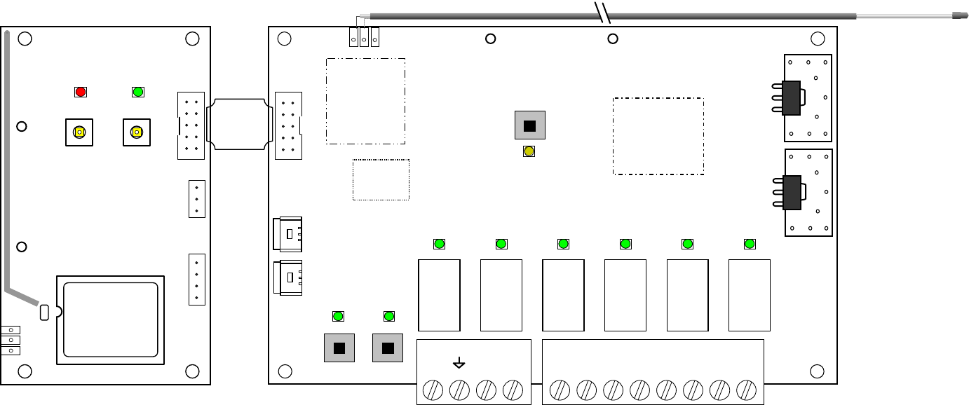
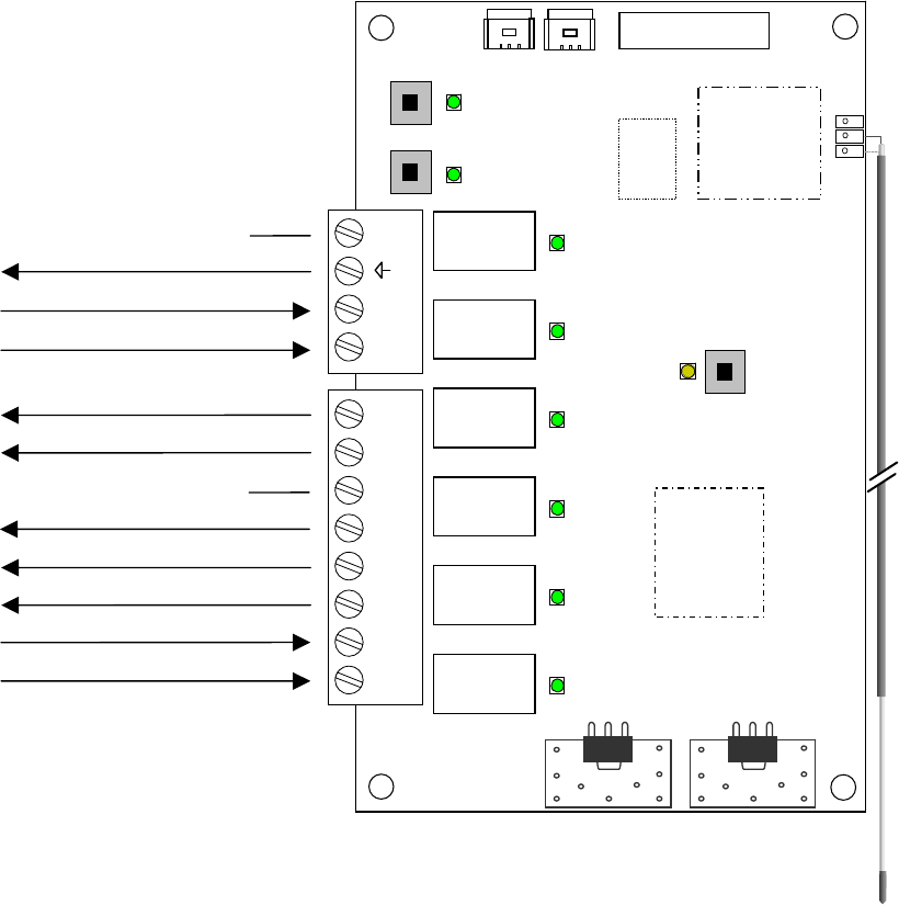
Figure 1 – Model 15700 EnOcean Support Module with 12200C RCN
J1
LED 4
PB 4
LED 5
PB 5
enocean
RF Module
J3
J4
ENERNET CORPORATION © 2018
MODEL: 15700
Ribbon Cable
PB3
D5
Network
Microcontroller
Area
D4 D3
PB1 PB2 E 1 2
G1 G2 G3 WO/B
Y
T1
T2
G2 W
Y
C RG3G1 O/B
916.5 MHz
Transceiver
Relay
K1
Relay
K5
Relay
K4
Relay
K3
Relay
K2
Relay
K6
Firmware
Version
Label
RESET
LINK
ENERNET CORPORATION © 2018
MODEL: 12200C
© 2014
J4
MODEL 15700 User Guide
© 2018 ENERNET Corporation • www.enernetcorp.com • 315-449-0839 Pub No. 15701-091918 / Page 8 of 16
GENERAL MOUNTING GUIDANCE
This section is intended to provide general guidance to system
integrators installing the ENERNET model 12200C Remote
Control Node hardware with the model 15700 EnOcean Devices
Support Accessory in or near HVAC equipment (HVAC equipment
generically referred to herein as appliance). Choosing the right
location to mount the model 15700 and 12200C RCN hardware is
key to maximizing performance and reliability. It should be
accessible to service personnel, where wire terminations and
buttons are easy to reach and indicator lights are visible.
Pay attention to environmental limits. Ensure the RCN isn’t in the
path of condensate, extreme heat, cold or physical interference.
Do not allow appliance parts or wires to contact the
pushbuttons. Unrelated wiring should be at least 2 inches
away from the board. More is better.
Do not Mount the RCN inside a box containing line voltage
circuits, wiring or relays.
Do not pick a mounting point that puts a service technician
in contact with line voltage circuits when performing
maintenance or linking the thermostat.
ANTENNA POSITIONING GUIDELINES
The 12200C utilizes a 1-meter long coaxial cable antenna, giving
installers the ability to locate the 12200C PCB where appropriate
and secure, while positioning the antenna in the most optimum
position possible for RF performance. In that the 12200C
hardware participates in a building-wide mesh network, its antenna
placement can be critical, therefore the coaxial antenna is the
default standard. 15700 hardware plugs onto the 12200C with a
short length of ribbon cable and while designed to support several
antenna styles, the default antenna style is a PCB trace element.
Therefore, the 15700 antenna is located at the PCB itself. The
15700 communicates only with close by devices, room, motion,
door switches, and does not participate in mesh network traffic. In
general, RF performance is less critical. However, if an appliance
installation results in poor RF performance of the 15700 due to
metal shielding effects, a non metallic satellite enclosure outside
the appliance should be considered to house the 12200C/15700
pair.
MODEL 12200C RCN — COAXIAL ANTENNA
The model 12200C control node standard antenna option is a 1-
meter long flexible coaxial cable. One end is permanently
connected at the circuit board. Approximately 3” of the outside
jacket and shield are striped back at the free end — this is the
actual antenna. The coaxial antenna option allows the installer to
mount the circuit board where most appropriate and secure, while
positioning the antenna in the most optimum position possible.
Sheet metal, control boxes, ductwork, pipes and other electrical
wires can interfere with RF signals to and from the control node.
For best performance, installers should location the antenna away
from such shielding material to the extent possible. In PTAC
equipment, the antenna is often located in front of the indoor coil,
between the coil and the PTAC cover if the cover is plastic or near
the makeup air opening at the bottom of the unit if it is metal. As is
MODEL 15700 User Guide
© 2018 ENERNET Corporation • www.enernetcorp.com • 315-449-0839 Pub No. 15701-091918 / Page 9 of 16
the case with any RF system, antenna placement and orientation
is important. If you experience difficulty maintaining a reliable RF
link with your thermostat or mesh network, try relocating the
antenna, ensuring it is not blocked by or resting against sheet
metal, pipes or wires.
CARDINAL RULE, PART 1
A contiguous solid or screened metal box won’t pass radio waves
in or out. (This explains why your eyeballs don’t melt when you’re
watching popcorn cook in the microwave.) Best performance
requires positioning the antenna tip near an opening in the
enclosure. The opening should be as large as possible. A slot
shorter than the 3” antenna dimension will not couple well.
Opening width should be at least a quarter inch. Again, larger is
better.
Optimum antenna location is usually unrealistic. When inside an
appliance with plastic facade, look for a mounting point an inch or
so in front of chassis metal or indoor coil, between metal and the
cover. When a front cover is metal, at or near the makeup air
opening at the bottom of the unit is often best.
CARDINAL RULE, PART 2
For best performance the antenna tip should be spaced at least an
inch away from sheet metal, control boxes, ductwork, pipes and
wires. These can interfere with RF signals to and from the RCN.
Pay attention to how the coaxial cable is routed and attached. It
should be run by itself to the mounting point and attached securely
with plastic tie wraps or cable clamps. Excess antenna cable can
be coiled but make sure to leave at least 6 inches straight and free
at the antenna tip.
Do not bundle the coaxial cable with other wiring.
Do not allow the antenna tip to contact wires or sheet metal.
Do not make any electrical connection to the antenna
conductor or shield.
Make sure the coaxial cable is not chafed by vibrating parts.
CONCLUSION
As with any RF system, antenna placement and orientation is
important. Since radio waves reflect off objects in the appliance
as well as the room or inside the walls where the appliance is in
service, there can be sharp signal nulls or “dead spots” between
the RCN, particularly when mounted in an appliance and where
the user locates a thermostat or other sensors. By example, most
people have experienced this phenomenon while using a cordless
telephone or cell phone. While the final location and
circumstances of the appliance installation are unknown, following
the above guidance will improve final RF performance.
MODEL 15700 User Guide
© 2018 ENERNET Corporation • www.enernetcorp.com • 315-449-0839 Pub No. 15701-091918 / Page 10 of 16
SETTING ROOM / NODE / BUILDING NUMBERS
EnernetWorks™ is a mesh network connectivity protocol
embedded in 12200C-157 firmware. Each 12200C-157 Remote
Control Node (RCN) requires a unique identifier for building
automation system integration. Generally a room, office or
apartment number already exists and is used. 4-digit numbers in
the range of 1 - 8999 are loaded into a 12200C-157 RCN along
with a node number 0-7 to create a complete number.
Whether a permanent part of the system or not, an ENERNET
model 12400H or S thermostat is used to enter room numbers. It
must first be linked to a target 12200C-157 RCN. During the
process of linking, a node number is assigned.
Refer to Figures 2, 3 & 4 for inside thermostat button locations and
functions and display information.
LINKING 12400H & 12200C-157 — STEP ONE
1. Press SW4-INSTALL button inside the 12400H thermostat.
Install Icon will blink (see Figure 2 & 3).
2. Press the HEAT/COOL button on front. Default node
number is 00. Change as desired using the UP button.
3. With node number set, press the SW9-LINK button. The
“Please Wait” message appears on display (Figure 3).
Within 5 seconds, press and release PB3 on 12200C-157
PCB (see Figure 1).
4. A response of “good" should be displayed.
5. Press the SW4 - INSTALL button inside the thermostat to
exit.
ASSIGNING ROOM NUMBER — STEP TWO
1. Simultaneously press SW9-LINK and the DOWN button on
front of the 12400x thermostat. Four digits will be displayed
in the top left corner of the display (Figure 4).
2. Use UP and DOWN buttons to change blinking digit,
HEAT/COOL button to save and advance.
3. When all digits are set, press SW9-LINK (Figure 2) to send
number to the 12200C-157. The number you set should
remain displayed. If it changes to 9999, repeat steps 2 and
3 above.
4. Press the FAN button on 12400x to exit the room number
set up screen.
UNINSTALL 12400H THERMOSTAT — STEP THREE
If the 12400x thermostat is only being used as a field tool to enter
room numbers, it must be unlinked from the 12200C-157 RCN
before it is linked to the next RCN.
1. Press SW4-INSTALL button inside the 12400H thermostat
(Figure 2). Install icon on display will blink.
2. Press UP button, Uninstall icon on display will blink.
3. Press the SW9-LINK button, “Please Wait” message
appears.
4. Within 5 seconds, press and release PB3 on the 12200C-
157.
5. A response of “good" should be displayed.
Press the SW4 - INSTALL button inside the thermostat to exit.
MODEL 15700 User Guide
© 2018 ENERNET Corporation • www.enernetcorp.com • 315-449-0839 Pub No. 15701-091918 / Page 11 of 16
ROOM NUMBERING DISCUSSION
When setting a room number for an office, apartment or any area
where a single room number identifies a divided space with more
than one thermostat and RCN, use a different node number when
linking each RCN.
Example: Consider an office area designated 101 with three
individual offices, thermostats and RCN’s. Assume the offices are
numbered 101A, 101B and 101C. In office 101A, link the RCN as
node 00.
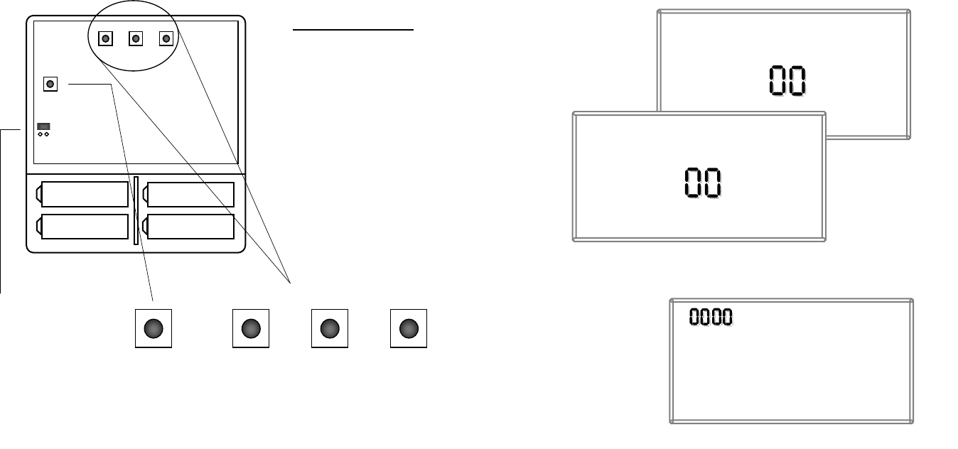
SW12-RESET SW4-INSTALL SW9-LINK
PB1-NETWORK
Set A Set A
Set B Set B
SW12- SW9-LINK Internal T9000 buttons
PB1-NETWORK
Used to uninstall the thermostat
from node(s) it has been linked
to.
SW12-RESET
Master Reset – Returns
thermostat to all factory
defaults.
SW4-INSTALL
Starts an installation session.
SW9-LINK
Used to Link the thermostat to
PB1-NETWORK
JP3 -
JP4 – Non
Program Jumper
JP3 = Programmable
JP4 = Non-Programmable
Figure 2 – Internal 12400H Buttons
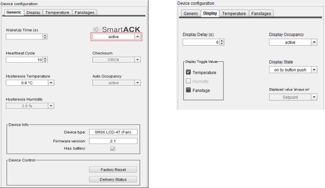
Install
Node
HEAT
COOL
Please Wait
Install
Node
Good
HEAT
COOL
Figure 3 – Install / Link Displa
y
Figure 4 – Room Number Digits

MODEL 15700 User Guide
© 2018 ENERNET Corporation • www.enernetcorp.com • 315-449-0839 Pub No. 15701-091918 / Page 12 of 16
(NOTE: Node numbers will automatically be incremented by “1”
over the network.) Then, using the procedure above set the room
number to 0101. In office 101B, link to that RCN as node 01 and
set that room number also to 0101. Finally, in office 101C, link
that RCN as node 02 and set that room number to 0101. The
resulting room/node numbers you have created will be:
Office 101A = 0101-01
Office 101B = 0101-02
Office 101C = 0101-03
Be sure to document your numbering scheme for BAS integration
and reference.
SETTING NETWORK / BUILDING NUMBER
In addition to a Room Number, each RCN in a network must also
have a unique Network Number (NetNum) or what is sometimes
referred to as a Building Number. DIP switches on the model
13800 gateway (see Pub No. 13801-022709_User Guide) set the
gateway’s NetNum. There are 255 possible network numbers, 1 –
255. Factory default NetNum of both a model 13800 gateway and
12200C-157 is 140.
A single gateway can support 400+ RCN’s. If a building has
significantly more than 400 nodes, a single network and gateway
can be overburdened with network traffic. This may require the
use of an additional gateway using a different NetNum.
The following procedure is used to set the desired RCN NetNum:
1. Simultaneously press SW9-LINK button inside the
thermostat and the DOWN button on the front. In the upper
left corner of the LCD, four digits will appear. The digit that
is blinking is the one ready to be changed.
2. Use UP and DOWN buttons to change blinking digit,
HEAT/COOL button to save and advance.
3. Network Numbers will always start with ‘9’ followed by the
desired three digit NetNum. Example:
9001
9002
.
.
.
9255 (default is 9140)
4. When all digits are set, press SW9-LINK to send the
NetNum to the RCN.
5. Press the FAN button to exit the network numbering set up
screen.
ATTENTION:
Do not use any ‘9000’ number other than 9001 through 9255 when
setting the Network Number — All other 9000 numbers are
reserved. Be sure to adjust the gateway NetNum to match what
you are putting into the 12200C-157 RCN. Refer to model 13800
gateway Pub No. 13801-022709_User Guide.
MODEL 15700 User Guide
© 2018 ENERNET Corporation • www.enernetcorp.com • 315-449-0839 Pub No. 15701-091918 / Page 13 of 16
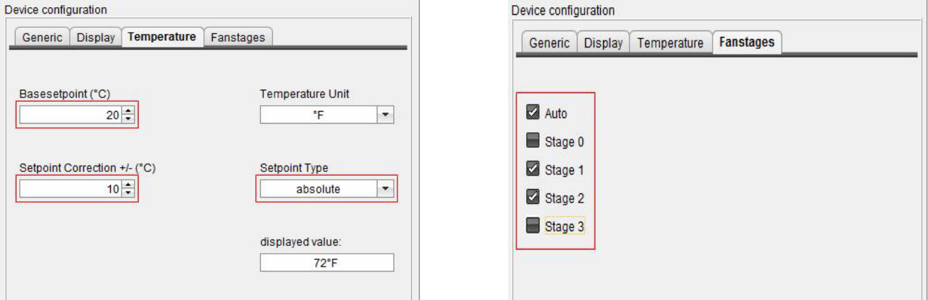
SR06 SETUP REQUIREMENTS
The 12200C-157 requires that the SR06 is setup as follows:
SmartACK
SmartACK can be set to active or not. Be sure to follow the Learn-
in procedure for SmartACK if using it.
The user should be aware that there are risks to enabling
SmartACK in terms of power consumption. Consult with
Thermokon before using this option.
240
MODEL 15700 User Guide
© 2018 ENERNET Corporation • www.enernetcorp.com • 315-449-0839 Pub No. 15701-091918 / Page 14 of 16
MODEL 15700 User Guide
© 2018 ENERNET Corporation • www.enernetcorp.com • 315-449-0839 Pub No. 15701-091918 / Page 15 of 16
EZ26 Connection Diagram
PB3
D5
Network
Microcontroller
Area
PB1
G1
T1
Expansion
Port
916.5 MHz
Transceiver
Relay
K1
Relay
K5
Relay
K4
Relay
K3
Relay
K2
Relay
K6
Firmware
Version
Label
RESET
LINK
T2
D4
PB2
G2 G3 WO/B Y
E 1 2 G2
W
Y
C R
G3
G1 O/B
C
R
Input 1 & 2 Common
GH
GL
B
Y
— Input 1 Aux Heat Current Switch
No Connection x
— Input 2 Cold Pipe Aquastat
No Connection x
Optional
Zone Valve
D3
Optional

MODEL 15700 User Guide
© 2018 ENERNET Corporation • www.enernetcorp.com • 315-449-0839 Pub No. 15701-091918 / Page 16 of 16
ENERNET CORPORATION PROVIDES THIS PUBLICATION “AS IS” WITHOUT WARRANTY OF ANY KIND, EITHER EXPRESS OR
IMPLIED, INCLUDING, BUT NOT LIMITED TO, THE IMPLIED WARRANTIES OF MERCHANTABILITY OR FITNESS FOR A PARTICULAR
PURPOSE.
THIS MANUAL MAY CONTAIN TECHNICAL INACCURACIES AND/OR TYPOGRAPHICAL ERRORS. CHANGES ARE PERIODICALLY
MADE TO THIS MANUAL, WHICH ARE INCORPORATED IN LATER EDITIONS.
ENERNET CORPORATION MAY MAKE CHANGES AND IMPROVEMENTS TO THE PRODUCT(S) AND/OR PROGRAMS DESCRIBED IN
THIS PUBLICATION AT ANY TIME WITHOUT NOTICE.
IN NO EVENT WILL ENERNET CORPORATION BE LIABLE FOR DAMAGES, INCLUDING LOST PROFITS, LOST SAVINGS OR OTHER
INCIDENTAL OR CONSEQUENTIAL DAMAGES ARISING OUT OF THE USE OF OR INABILITY TO USE SUCH PRODUCT, EVEN IF
ENERNET CORPORATION OR AN APPROVED RESELLER HAS BEEN ADVISED OF THE POSSIBILITY OF SUCH DAMAGES, OR FOR
ANY CLAIM BY ANY OTHER PARTY.
ENERNET
Corporation
307 Dewittshire Road, Syracuse, New York 13214
Phone: (315) 449-0839 Fax: (315) 449-3056