ENTERMEDIA ED11KTM Digital 2.4 GHz Data Transmitter User Manual USER Manual all
ENTERTECH CO., LTD. Digital 2.4 GHz Data Transmitter USER Manual all
User Manual

USER Manual
of
2.4 GHz Transceiver Module (ED11K-TM)
ENTER TECH CO., LTD.

FCC Operation Guide
This device complies with part 15 of the FCC Rules. Operation
is subject to the following two conditions:
(1) This device may not cause harmful interference, and
(2) This device must accept any interference received,
including interference that may cause undesired operation.
FCC Compliance Statement
This equipment has been tested and found to comply with the limits for a Class B digital
device, pursuant to part 15 of the FCC Rules. These limits are designed to provide
reasonable protection against harmful interference in a residential installation.
This equipment generates, uses and can radiate radio frequency energy and, if not installed and
used in accordance with the instructions, may cause harmful interference to radio
communications. However, there is no guarantee that interference will not occur in a particular
installation. If this equipment does cause harmful interference to radio or television reception,
which can be determined by turning the equipment off and on, the user is encouraged to try to
correct the interference by one or more of the following measures:
- Reorient or relocate the receiving antenna.
- Increase the separation between the equipment and receiver.
- Connect the equipment into an outlet on a circuit different from that to which the receiver is
connected.
- Consult the dealer or an experienced radio/TV technician for help.
RF exposure statement
The antenna(s) used for this transmitter must be installed to provide a separation distance of
at least 20 cm from all persons and must not be co-located or operating in conjunction with any
other antenna or transmitter.
Any changes or modifications to the equipment not
expressly approved by the party responsible for compliance
could void user’s authority to operate the equipment.
End Product Labeling
This transmitter module is authorized only for use in devices where the antenna may be
installed such that 20 cm may be maintained between the antenna and users. The final end
product must be labeled in visible area with the following:
"Contains TX FCC ID: PBNED11KTM "
End Product Manual Information
The user manual for end users must include the following information in a prominent location:
"IMPORTANT NOTE:
To comply with FCC RF exposure compliance requirements, the antenna used for this
transmitter must be installed to provide a separation distance of at least 20cm from all persons
and must not be co-located or operating in conjunction with any other antenna or transmitter."
IMPORTANT NOTE:
FCC Radiation Exposure Statement:
This equipment complies with FCC radiation exposure limits set forth for an uncontrolled
environment. End users must follow the specific operating instructions for satisfying RF
exposure compliance.
This device is intended only form OEM integrators under the following conditions:
1. The antenna must be installed such that 20cm is maintained between the antenna and users,
and
2. The transmitter module may not be co-located with any other transmitter or antenna.
IMPORTANT NOTE: In the event that these conditions can not be met (for example
certain portable configurations or co-location with another transmitter), then the FCC
authorization is no longer considered valid and the FCC ID can not be used on the final product.
In these circumstances, the OEM integrator will be responsible for re-evaluating the
end product (including the transmitter) and obtaining a separate FCC authorization.
1. General Description
The ED11K-TM joined to the Test-Jig is a transceiver module. It transmits
analog audio signal input by RF modem with an integrated A/D Converter supports
16 bits and 24 kHz sampling rates.
This module contains RF modem supports 2.4 GHz ISM BAND.
This module can select one channel out of 79 channels with pairing address so that it
distinguishes one from another. This channel must be equal to pairing address of the
ED11K-RM, a receiver module. Be sure to use this module with ED11K-RM together
for normal mode operation.
The main usage of this module is for CLP(Cordless Phone), Wireless MIC, Wireless
Serial Port and so on.
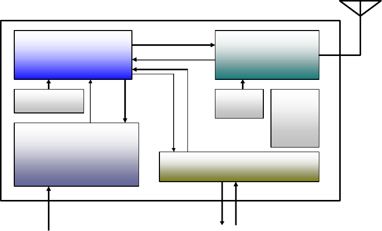
2. Module Block Diagram
RF Transceiver Module(TX)
U1
Wireless Modem
CPU
(Retaw-04)
Key Control
Interface
U2
2.4G Transciever
(nRF-2401)
U3
Stereo A/D
converter
(CS5333)
CE /CS
CLK / DATA
AD OUT
DATA
ANT
XTAL
12.288MHz XTAL
16MHz
DATA
IN
Key
Out Key
In
Key
Out Key
In
CLK
U4
Drop
Regulator
(NJM2882)

3. Pin Assign
1 20
2 19
3 18
4 17
5 16
6 15
7 14
8 13
9 12
10 11

4. Pin Description
PIN Pin Function Description
1 VCC DC3.3V
2 GND GND
3 KEY IN0 Key Data IN
4 KEY IN1 Key Data IN
5 KEY IN2 Key Data IN
6 KEY IN3 Key Data IN
7 CHARGE Charging Detect
High : Not charging
Low : Charging
8 POWER ON Power On
High : System ON
Low : System OFF
9 POWER SW Power SW
High : Default
Low : Power SW On
10 UART RX UART RX : Program download
11 UART TX UART TX : Program download
12 BOOT Low : Program Download Mode
High : Not Program Download Mode
13 ADC IN Voice Input
14 LOW BATT CHECK
High : Full Charge
Low : Charging
15 LED0(GREEN) Not Link : Red,Green Toggle Turn On,Off
Link : Green Toggle Turn On,Off
Charging : Red Turn On
16 LED1(RED) Not Link : Red,Green Toggle Turn On,Off
Link : Green Toggle Turn On,Off
17 KEY OUT3 Key Out
18 KEY OUT2 Key Out
19 KEY OUT1 Key Out
20 KEY OUT0 Key Out
5. KEY MAP COMMAND
key code key Code
1 0x01,0x7e,0xf6 2 0x02,0x7d,0xf6
3 0x03,0x7c,0xf6 4 0x04,0x7b,0xf6
5 0x05,0x7a,0xf6 6 0x06,0x79,0xf6
7 0x06,0x78,0xf6 8 0x08,0x77,0xf6
9 0x09,0x76,0xf6 0 0x00,0x7f,0xf6
DOWN 0x1E,0x61,0xf6 UP 0x1F,0x60,0xf6
MODE 0x1C,0x63,0xf6 RES 0x1D,0x62,0xf6
PAUSE / STOP (0x0F, 0x70,0xf6)
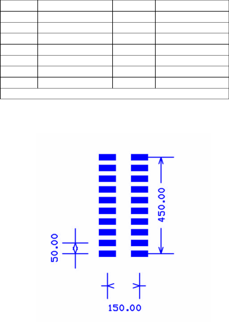
6. Pin Dimension
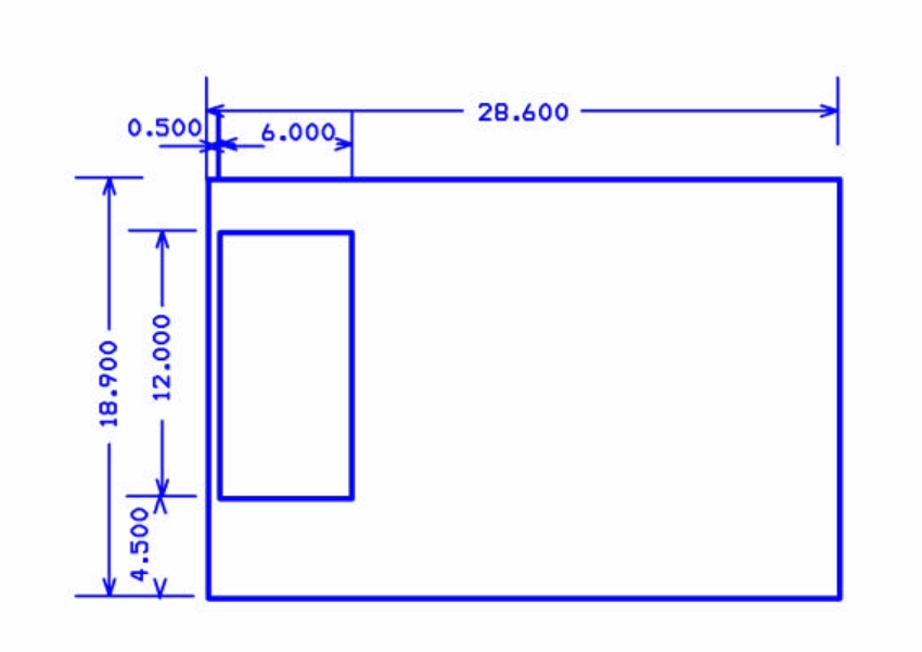
7. Module Dimension