User manual

EZBee series Manual / Ver. 1.0
--------------------------------------------------------------------------------------------------------------------------
E
EZ
ZB
Be
ee
e
s
se
er
ri
ie
es
s
M
Ma
an
nu
ua
al
l
2008. 11.
AHHA-Tech

EZBee series Manual / Ver. 1.0
--------------------------------------------------------------------------------------------------------------------------
2
CONTENTS
CONTENTSCONTENTS
CONTENTS
Contents ............................................................................................................................................................................ 2
1. Products Overview ............................................................................................................................................... 6
2. EZBee M100 ............................................................................................................................................................... 8
2.1. Specificaion of EZBee M100 .................................................................................................................... 8
2.2. EZBee M100 PIN Assignments ............................................................................................................... 9
2.3. EZBee M100 Dimension .......................................................................................................................... 10
2.4. EZBee M100 LED Display ........................................................................................................................ 10
3. EZBee S100 ................................................................................................................................................................. 11
3.1. Specificaion of EZBee S100 ................................................................................................................. 11
3.2. Configuration of EZBee S100 ............................................................................................................. 12
3.2.1. RS-232 mode ................................................................................................................................ 12
3.2.2. RS-422/485 mode ......................................................................................................................... 12
3.3. DIP switch setting ....................................................................................................................................... 13
3.4. EZBee S100 LED display .......................................................................................................................... 14
4. EZBee U100 ................................................................................................................................................................. 15
4.1. Specificaion of EZBee U100 ................................................................................................................. 15
4.2. Configuration of EZBee U100 ............................................................................................................... 16
4.3. EZBee U100 LED display .......................................................................................................................... 17
3
5. EZBee L100 .................................................................................................................................................................. 18
5.1. Specificaion of EZBee L100 .................................................................................................................. 18
5.2. Configuration of EZBee L100 ............................................................................................................... 19
5.3. Network Setting .......................................................................................................................................... 19
5.3.1. Using Web browser ...................................................................................................................... 19
5.3.2. Using EZBee manager program ............................................................................................. 21
5.4. Menu related to communication of EZBee L100 ....................................................................... 22
5.5. Communication modes of EZBee L100 ............................................................................................ 23
5.6. EZBee-L100 LED display ........................................................................................................................ 23
6. AT Command ............................................................................................................................................................. 24
6.1. Reference table of AT Commands...................................................................................................... 24
6.2. Notification message ................................................................................................................................ 25
6.3. Result message............................................................................................................................................ 26
7. Description of AT Commands............................................................................................................................ 27
7.1. Serial communication interface ........................................................................................................... 27
7.1.1. Serial port setting ......................................................................................................................... 28
7.1.2.Echo mode setting ........................................................................................................................ 27
7.2. EZBee modem setting.............................................................................................................................. 27
7.2.1.channel setting ................................................................................................................................ 29
7.2.2. PAN ID setting ............................................................................................................................... 30
7.2.3. Modem ID setting ........................................................................................................................ 31
7.2.4. Group ID setting ........................................................................................................................... 32
4
7.2.5. Receiver ID setting for Bypass mode .................................................................................. 33
7.2.6. Automatic start mode setting ................................................................................................ 33
7.2.7. Starting EZBee network ............................................................................................................. 34
7.3. Network message transmission ........................................................................................................... 35
7.3.1. Data transmission in ASCII mode ......................................................................................... 35
7.3.2. Data transmission in Bypass mode ...................................................................................... 37
7.4. Reading a Short-address ........................................................................................................................ 40
7.5. Reading an Extended address .............................................................................................................. 40
7.6. Resetting a Modem................................................................................................................................... 41
7.7. Resetting a Network ................................................................................................................................. 41
7.8. Reading a modem version ..................................................................................................................... 42
7.9. Reading a modem status ....................................................................................................................... 42
7.10. GPIO control and setting..................................................................................................................... 42
7.10.1. GPIO direction setting ............................................................................................................. 43
7.10.2. GPIO control ................................................................................................................................ 44
7.10.3. ADC reading................................................................................................................................. 45
7.11. Remote control allowance setting ................................................................................................... 45
7.12. PAN joining allowance setting ........................................................................................................... 46
8. EBI Commands ......................................................................................................................................................... 47
8.1. EBI mode overview .................................................................................................................................... 47
8.2. EBI mode communication ...................................................................................................................... 47
8.3. EBI packet type ............................................................................................................................................ 48
8.3.1. EBI_TYPE_UNICAST_MSG ........................................................................................................... 48
5
8.3.2. EBI_TYPE_GROUP_MSG .............................................................................................................. 48
8.3.3. EBI_TYPE_BROAD_MSG ............................................................................................................... 49
8.3.4. EBI_TYPE_ACK ................................................................................................................................. 49
8.3.5. EBI_TYPE_IO_REQ .......................................................................................................................... 50
8.3.6. EBI_TYPE_IO_ACK .......................................................................................................................... 50
8.3.7. EBI_TYPE_IOD_REQ ....................................................................................................................... 51
8.3.8. EBI_TYPE_IOD_ACK ....................................................................................................................... 51
8.3.9. EBI_TYPE_ADC_REQ ...................................................................................................................... 52
8.3.10. EBI_TYPE_ADC_ACK ................................................................................................................... 52
8.3.11. EBI_TYPE_ESCAPE ....................................................................................................................... 52
Appendix
How to use EZBee M100 53
EZBee series Manual / Ver. 1.0
6
1.
1. 1.
1. Products Overview
Products Overview Products Overview
Products Overview
EZBee
TM
formats include OEM modules (M100), industrial serial
adapters (S100), USB type serial adapters (U100), and internet access
points (L100) for supporting various customers who need to get wireless
solutions in industrial automation, medical automation, building automation,
information technology, retail/ POS and so on.
The EZBee
TM
series is a 2.4GHz ISM band transceiver, based on the
Chipcon CC2420 chip for IEEE 802.15.4. The EZBee
TM
series supports
various AT- style command line interfaces for allowing customers to quickly
build mesh networks requiring lower power consumption without skillful
wireless RF engineering and complex software engineering. It also
provides 2 ADC ports and 8 I/ O ports for enabling customers to
conveniently design own embedding systems.
The EZBee
TM
series implements three different data transmission
modes including ASCII, Bypass and EBI (EZBee Binary Interface) mode.
In ASCII mode, all data are transmitted as format of ASCII HEX by
utilizing the AT command sets for data transmission.
In Bypass mode, all raw data are transmitted to the pre- assigned
EZBee module without utilizing any specific commands or building any
communication packet, as if EZBee modules are wired together.
In EBI mode, the transmitting data packets can be configured by

EZBee series Manual / Ver. 1.0 7
customers for more flexible and effective communication.
A specified own ID and an extended/ short address are assigned for
each modem of EZBee formats. The specified own ID is used for pointing
a data receiving modem in every data transmission modes.
The specifications of EZBee
TM
is summarized as follows:
EZBee Specifications
Communication range 2500m (LOS)
TX power 0 dBm ~ 18 dBm (selectable by software)
RF Data Rate 250,000 bps
Serial Interface Data Rate 1,200 – 115,200 bps (selectable by software)
Receive sensitivity -100dBm (packet error ratio 1%)
Supported Network Topologies Point-to-point, point-to-multipoint, peer-to-peer
Number of Channels 16 direct sequence channels (selectable by
software)
Addressing Options PAN ID, Channel, Addresses
EZB
EZBEZB
EZB-
--
-S100,
S100, S100,
S100, EZB
EZBEZB
EZB-
--
-U100
U100U100
U100
and
andand
and
EZB
EZBEZB
EZB-
--
-L100
L100L100
L100
comply
complycomply
comply
with part 15 of the FCC Rules. Operation is
with part 15 of the FCC Rules. Operation is with part 15 of the FCC Rules. Operation is
with part 15 of the FCC Rules. Operation is
subject to
subject tosubject to
subject to
the following two conditions:
the following two conditions: the following two conditions:
the following two conditions:
(1) This device may not cause harmful interference, and
(1) This device may not cause harmful interference, and (1) This device may not cause harmful interference, and
(1) This device may not cause harmful interference, and
(2) this device must accept any interference received, including
(2) this device must accept any interference received, including(2) this device must accept any interference received, including
(2) this device must accept any interference received, including
interference that may
interference that may interference that may
interference that may
cause undesired operation.
cause undesired operation.cause undesired operation.
cause undesired operation.
EZBee series Manual / Ver. 1.0 8
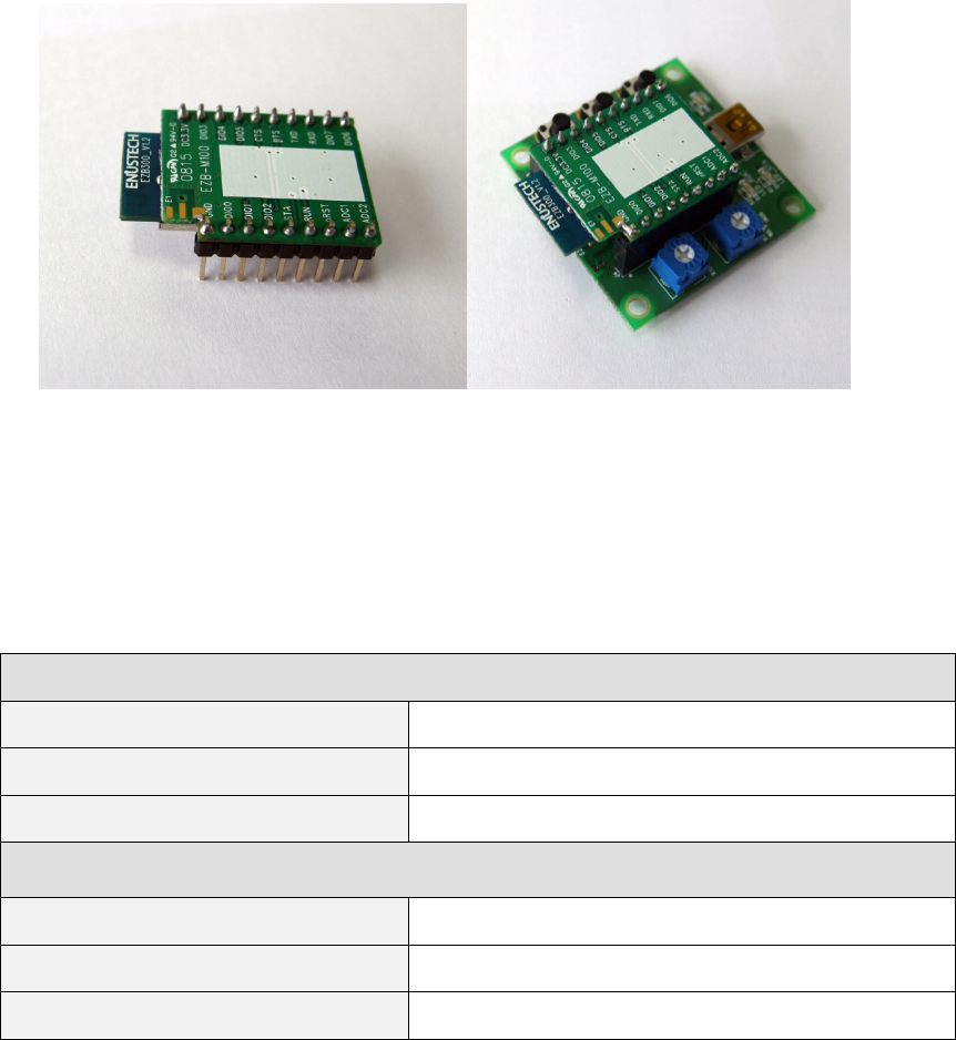
2. EZBee M100
EZBee M100 based on IEEE 802.5.4 specification, is designed for an
embedded solution to provide stable wireless communication with low
power consumption.
2.1 Specification of
2.1 Specification of 2.1 Specification of
2.1 Specification of EZBee
EZBeeEZBee
EZBee
M100
M100 M100
M100
General Specifications
Operating Frequency ISM 2.4 GHz ISM 2.4 GHz
Dimension
*
32.0mm(L) x 22.0mm(W) x 10.5mm(H)
Operating Temperature -25 ~ 85º C
Electrical Specifications
Supply Voltage 2.7~3.6V
Transmit Current(typical) 190mA
Idle/Receive Current(typical) 27mA

EZBee series Manual / Ver. 1.0 9
2.2
2.22.2
2.2 EZBee
EZBeeEZBee
EZBee
M100 PIN Assignments
M100 PIN AssignmentsM100 PIN Assignments
M100 PIN Assignments
PIN Name Direction Description
1 GND - Power Ground
2 DIO0 Input / Output Digital Input or Output
3 DIO1 Input / Output Digital Input or Output
4 DIO2 Input / Output Digital Input or Output
5 STA Output Status LED
6 RUN Output Active LED
7 nRST Input RESET, Low Active
8 ADC1 Input Analog to Digital Converter
9 ADC2 Input Analog to Digital Converter
10 DIO6 Input / Output Digital Input or Output
11 DIO7 Input / Output Digital Input or Output
12 RXD Input UART Data
13 TXD Output UART Data
14 RTS Output UART Request to Send
15 CTS Input UART Clear to Send
16 DIO5 Input / Output Digital Input or Output
17 DIO4 Input / Output Digital Input or Output
18 DIO3 Input / Output Digital Input or Output
19 DC 3.3V - Power supply 3.3V

EZBee series Manual / Ver. 1.0 10
2.3
2.32.3
2.3 EZBee
EZBeeEZBee
EZBee
M100 Dimension
M100 DimensionM100 Dimension
M100 Dimension
Dimension
*
2.4
2.42.4
2.4 EZBee
EZBeeEZBee
EZBee
M100 LED
M100 LED M100 LED
M100 LED Display
DisplayDisplay
Display
LED display
ACT LED
(blue colour)
Flash when data are transmitted (Tx/Rx mode)
STA LED
(orange colour)
When the device is not joined in PAN
-
Repeat Turning ON during 1 second and OFF during 1 second
When the device is joined in PAN
-
In
ASCII MODE
:
ON contin
u
ously
- In EBI MODE : Repeat flashing twice every 0.5 second and turning
OFF
during
0.5 second
- In BYPASS MODE : Repeat Turning ON during 0.5 second and OFF
during 0.5 second
※ Please refer Appendix for how to use EZBee M100.
※ EZBee M100- S (MMCX Type) has a connection point for an external
antenna.
EZBee series Manual / Ver. 1.0 11
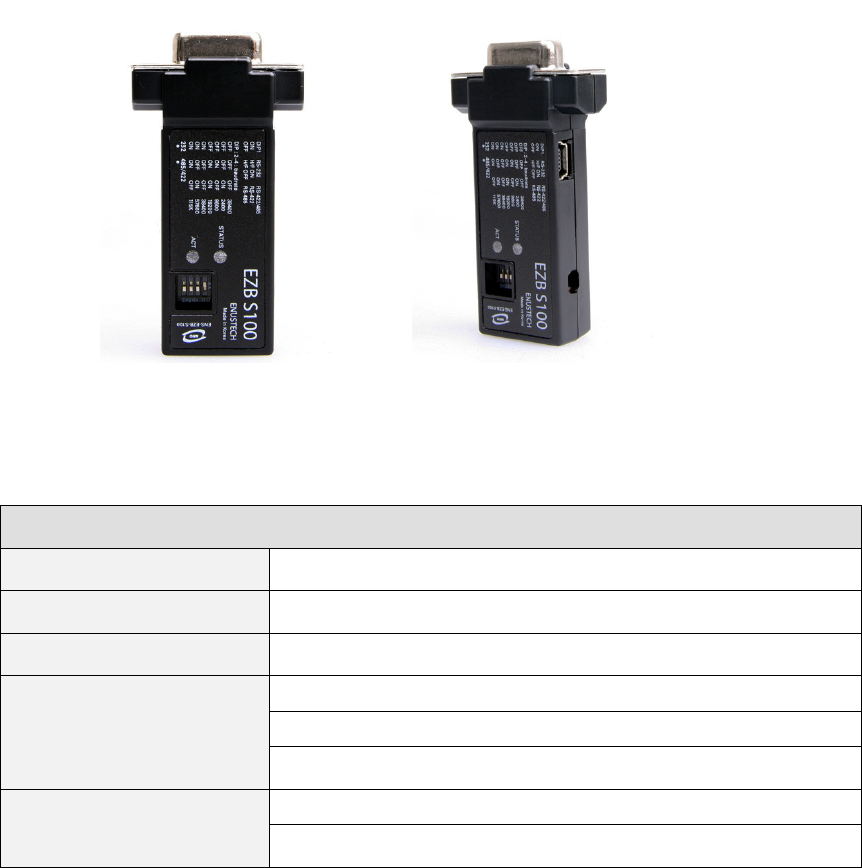
3
33
3 EZBee
EZBeeEZBee
EZBee
S100
S100S100
S100
EZBee S100 is designed to communicate with other devices based on
IEEE 802.5.4 specification without installing any serial cable. Two EZBee
S100 serial adaptors are connected to each other immediately when power
is supplied. If 38,400 baud rate is set for stable transmission, a pair of
S100 is able to connect without any extra setting.
3.1 Specification of EZBee S100
General Specifications
Voltage DC 4.5V~DC 5.5V (mini usb type jack or DSUB 9 pin)
Hardware interface RS-232, RS-422, RS-485
LED display On/Off, current status
Operating environment Operating temperature: -25~70 º C
Storage temperature: -25~70 º C
Humidity: 0 ~ 90% non-condensing
Physical properties Dimension: 31mm(w) x 15mm(H) x 60mm(L)
Weight: 16g
EZBee series Manual / Ver. 1.0 12
3.2
3.23.2
3.2 Configuration of
Configuration of Configuration of
Configuration of EZBee
EZBeeEZBee
EZBee
S100
S100S100
S100
Configuration method for a serial adaptor can be divided for RS- 232
and RS- 422/ 485 communication mode.
The baud rate of each communication mode is set by only DIP switches
on the EZBee S100.
3.2.1
3.2.13.2.1
3.2.1 RS
RSRS
RS-
--
- 232
232232
232
communication mode
communication modecommunication mode
communication mode
1 Selection switch for 232 or 422/ 485 is pushed to the 232 side.
2 Flow control method and baud rate for serial communication are set
by DIP switches.
3 EZBee S100 is connected to the serial port of a PC or DTE.
4 A mini USB cable protruded from a PC USB port or DC adaptor
should be connected to the mini USB port on EZBee S100 for
power supply.
3.2.2
3.2.23.2.2
3.2.2 RS
RSRS
RS-
--
- 422/ 485 communica
422/ 485 communica422/ 485 communica
422/ 485 communicati
titi
tion mode
on modeon mode
on mode
1 Selection switch for 232 or 422/ 485 is pushed to the 422/ 485 side.
2 The 422 or 485 mode is selected by DIP switches.
3 The baud rate for serial communication is set by DIP switches.
4 A mini USB cable protruded from a PC USB port or DC adaptor
should be connected to the mini USB port on EZBee S100 for
power supply.
EZBee series Manual / Ver. 1.0 13
3.3
3.33.3
3.3 Dip switch setting
Dip switch settingDip switch setting
Dip switch setting
►
►►
►
DIP1 mode setting
RS-232 mode RS-422/485 mode
DIP1 ON Hardware Flow Control ON RS-422
DIP1 OFF Hardware Flow Control OFF RS-485
►
►►
►
Baud rate setting
Baud rate DIP2 DIP3 DIP4
38400 bps OFF OFF OFF
2400 bps OFF OFF ON
9600 bps OFF ON OFF
19200 bps OFF ON ON
38400 bps ON OFF OFF
57600 bps ON OFF ON
115K bps ON ON OFF
38400 bps ON ON ON
ON
4
2 3 1

EZBee series Manual / Ver. 1.0 14
► DSUB 9 Pin Definition
Pin Number RS-232 RS-422 RS-485
1 DCD
2 TXD RXD- TXD-/RXD-
3 RXD TXD-
4 DTS
5 GND
6 DTR
7 CTS RXD+
8 RTS TXD+ TXD+/RXD+
9 DC Input DC Input DC Input
3.4
3.43.4
3.4 EZBee
EZBeeEZBee
EZBee
S100 LED
S100 LED S100 LED
S100 LED display
displaydisplay
display
LED display
ACT LED
(blue colour)
Flash when data are transmitted (Tx/Rx mode)
STA LED
(orange colour)
When the device is not joined in PAN
-
Repeat Turning ON during 1 second and OFF during 1 second
When the device is joined in PAN
-
In
ASCII MODE
:
ON contin
u
ously
- In EBI MODE : Repeat flashing twice every 0.5 second and turning
OFF
during
0.5 second
- In BYPASS MODE : Repeat Turning ON during 0.5 second and OFF
during 0.5 second
5
5 5
5
4
4 4
4
3
3 3
3
2
2 2
2
1
11
1
9 8 7 6
9 8 7 6 9 8 7 6
9 8 7 6

EZBee series Manual / Ver. 1.0 15
4
44
4 EZBee
EZBeeEZBee
EZBee
U100
U100U100
U100
EZBee U100, a dongle type EZBee format, makes it easy monitor and
control the devices on a PC or hand- held device. In addition, it can be
utilized as a router for IEEE 802.15.4 network for extending communication
range or overcoming weak signal strength in certain area.
4.1
4.14.1
4.1
Specification of
Specification of Specification of
Specification of EZBee
EZBeeEZBee
EZBee
U100
U100 U100
U100
General Specifications
Voltage DC 4.5V~DC 5.5V (mini usb type jack)
Hardware interface USB 2.0
LED display On/Off, current status
Identification on PC USB to Serial device
Operating environment Operating temperature: -25~70 º C
Storage temperature: -25~70 º C
Humidity: 0 ~ 90% non-condensing
Physical properties Dimension: 19.5mm(w) x 8.5mm(H) x 54mm(L)
Weight: 9g
EZBee series Manual / Ver. 1.0 16
4.2
4.24.2
4.2 Configuration of
Configuration of Configuration of
Configuration of EZBee
EZBeeEZBee
EZBee
U100
U100U100
U100
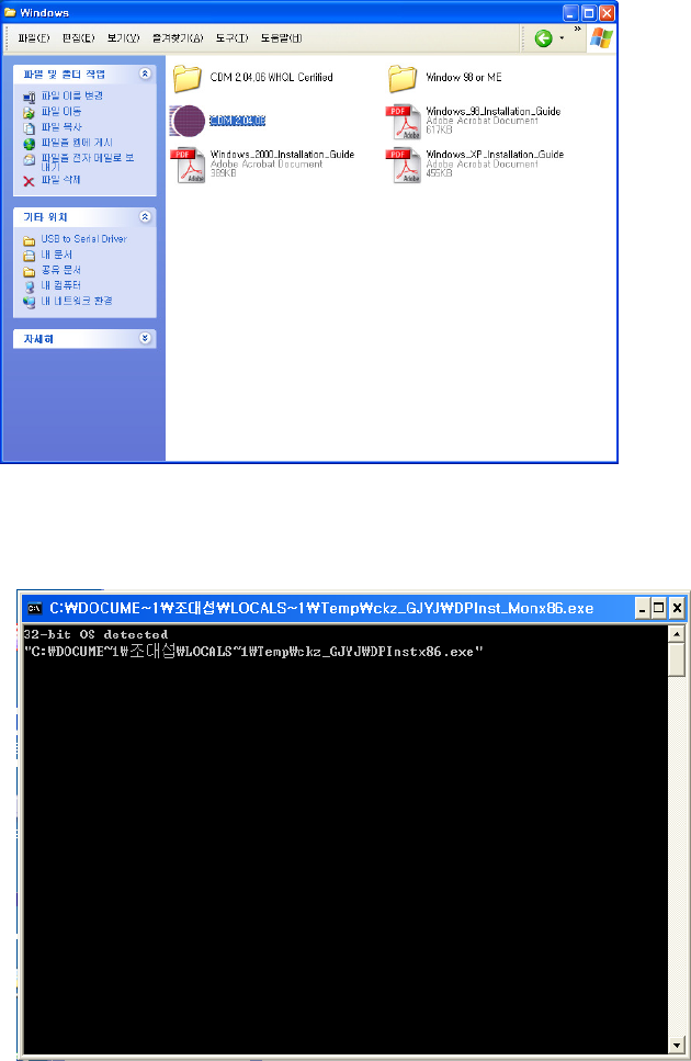
1 To use the EZBee U100 on a PC, a USB port connecting U100
should be set as a virtual conventional COM port in the PC.
2 For virtual COM port setting, the FTDI driver should be installed on
PC by running the CDM 2.04.06 on the enclosed CD.
Suporting OS : Window, MAC, Linux
3 The FTDI driver is installed automatically as shown.
EZBee series Manual / Ver. 1.0 17
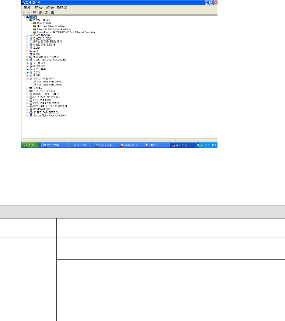
4 After virtual COM port setting, please find the COM port number at
port (COM or LPT) of device manager.
4.3
4.34.3
4.3 EZBee
EZBeeEZBee
EZBee
U100 LED
U100 LED U100 LED
U100 LED display
displaydisplay
display
LED display
ACT LED
(blue colour)
Flash when data are transmitted (Tx/Rx mode)
STA LED
(orange colour)
When the device is not joined in PAN
-
Repeat Turning ON
during 1 second and OFF during 1 second
When the device is joined in PAN
-
In
ASCII MODE
:
ON contin
u
ously
- In EBI MODE : Repeat flashing twice every 0.5 second and turning
OFF
during
0.5 second
- In BYPASS MODE : Repeat Turning ON during 0.5 second and OFF
during 0.5 second

EZBee series Manual / Ver. 1.0 18
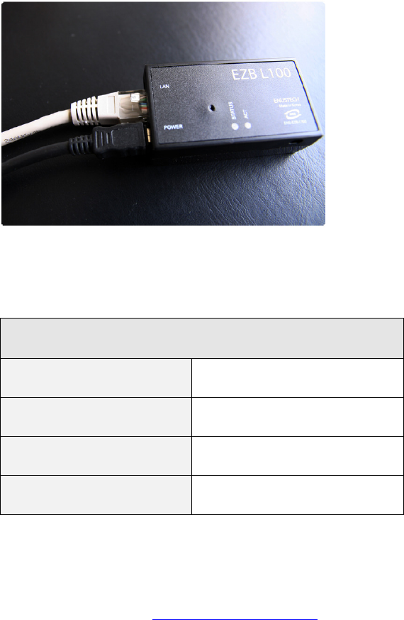
5
55
5 EZBee
EZBeeEZBee
EZBee
L100
L100L100
L100
EZBee L100 acts as a bridge between the devices based on IEEE
802.5.4 network and conventional TCP/ IP network. When sensor data are
collected through wireless network, EZBee L100 provides the sensor data
into the TCP/ IP network enables user to monitor the process.
5.1
5.15.1
5.1
Specification of
Specification of Specification of
Specification of EZBee
EZBeeEZBee
EZBee
L100
L100 L100
L100
General Specifications
Voltage DC 4.5V~DC 5.5V (mini usb type jack)
Ethernet Interface 10/100 Base-T Ethernet with RJ45 jack
LED display On/Off, current status
Network protocol HTTP, DHCP Client
Communication setting Web, Manager Program
Operating environment Operating temperature: 0~70 º C
Storage temperature: -25~70 º C
Humidity: 0 ~ 90% non-condensing
Physical properties Dimension: 35mm(W) x 20.5mm(H) x 64.5mm(L)
Weight: 30g
EZBee series Manual / Ver. 1.0 19
5.2
5.25.2
5.2 Configuration of
Configuration of Configuration of
Configuration of EZBee
EZBeeEZBee
EZBee
L100
L100L100
L100
Firstly a LAN connector for TCP/ IP network should be connected to a
LAN port prepared on EZBee L100. For the power supply, please connect a
mini USB cable protruded from a PC USB port or DC adaptor into the mini
USB port on EZBee L100.
5.3
5.35.3
5.3 Network Setting
Network SettingNetwork Setting
Network Setting
Initial setting
IP 172.17.52.164
Netmask 0.0.0.0
Gateway 0.0.0.0
default password enus
5.3.1
5.3.15.3.1
5.3.1 Using web browser
Using web browserUsing web browser
Using web browser
1 Connect to http:/ / 172.17.52.164 on web browser. In this moment,
please check the IP and Netmask of the PC whether it can access
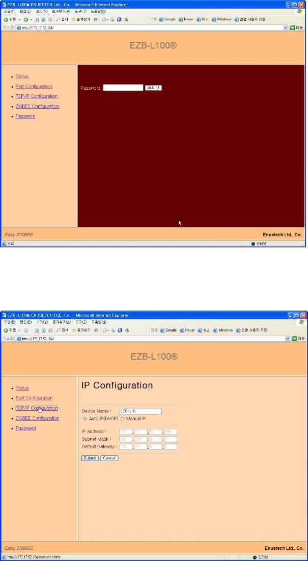
EZBee series Manual / Ver. 1.0 20
to default IP.
2
Type enus as the default password
3
After set your network IP at [ TCP/ IP configuration ] , reboot the
EZBee L100.
EZBee series Manual / Ver. 1.0 21
5.3.2
5.3.25.3.2
5.3.2 Using
Using Using
Using EZBee
EZBee EZBee
EZBee manager
manager manager
manager program
programprogram
program
The EZBee manager program is an utility program developed for easy
setting and management of a EZBee L100.
Useful function for setting : <scanning broadcasting device>
The useful function of the EZBee manager program is a scanning
broadcasting device. It searches and shows all list of EZBee L100
connecting to the same network of a user computer.
1 Click the button denoting [start search].
2 A list of all EZBee L100 connecting to the network is displayed when
the automatic scanning is over.
3 When you want to change the setting of one U100 among the list,
move the mouse point onto that EZBee L100 and just click the right
button of a mouse, then you can change the parameter from the
displaying menu.

EZBee series Manual / Ver. 1.0 22
5.4
5.45.4
5.4 Menu related to communication of
Menu related to communication of Menu related to communication of
Menu related to communication of EZBee
EZBeeEZBee
EZBee
L100
L100 L100
L100
Status Monitoring Shows current status of the EZBee L100
Port configuration Set operation of the EZBee L100
- Active connection :
EZBEE L100 acts as a client of TCP/IP network, and tries to
connect to a designated server.
- client connecting time (period) :
When a port is assigned as TCP/IP client, the assigned port
tries to connect to the specified host IP by the period of client
connecting time.
- KeepAlive Enable:
Check whether the TCP/IP connection is alive or not.
- KeepAlive Interval:
In case of setting ‘KeepAlive Enable’ function, it checks
whether the connection is alive or not when data is not
transmitted to the specified port during a period of time.
- Port Setting:
port number: TCP port number
Active: Active TCP connection request. Client mode
Server IP: IP address for active connection
P-P: peer-to-peer mode setting for EZBee
- Communication:
P-P: peer-to-peer mode set for wirelss communication
MODULE ID: Module ID
TCP/IP
Configuration
- Device Name: assign the name of EZBee L100.
- Set the specified IP address.
EZBee Set channel ID, PAN ID, group ID and module ID

EZBee series Manual / Ver. 1.0 23
Configuration
5.5
5.55.5
5.5 Communication modes of
Communication modes of Communication modes of
Communication modes of EZBee
EZBeeEZBee
EZBee
L100
L100 L100
L100
EZBee- L100 supports the TCP/ IP socket programming. It can be
assigned as a client or server according to each ports and handles data as
unit of packet.
The packet format is selectable among the EBI mode, P- P(Peer to Peer,
Bypass mode), according to the port. The default setting is the EBI mode,
enables to communicate any modules connecting to same socket. When
the P- P mode is selected, it switched to the Bypass mode, and enable to
communicate without the specified module or header data.
5.6
5.65.6
5.6 EZBee
EZBeeEZBee
EZBee
L100 LED
L100 LEDL100 LED
L100 LED
display
displaydisplay
display
LED display
ACT LED
(blue color)
Flash when data are transmitted (Tx/Rx mode)
STA LED
(orange color)
In case of turning ON denotes EZBee L100 is joined in the
network, and ready to communicate with
other EZBees.
In case of flashing denotes EZBee L100 is not joined in the
network.

EZBee series Manual / Ver. 1.0 24
6.
AT
AT AT
AT Command
CommandCommand
Command
The EZBee formats support various AT commands for controlling the
modem. Customers can configure the desired characteristics of a
specific network using the rich AT commands
6.1 Reference table for
6.1 Reference table for 6.1 Reference table for
6.1 Reference table for AT
AT AT
AT Commands
CommandsCommands
Commands
AT
command
Category
Description Parameter Default
D System Change modem mode to
‘BYPASS’ mode <Modem ID>
B System Change modem mode to ‘EBI’
mode None
Z System Modem reset None
NZ System Modem reset with erase
network states None
V System Show modem version None
S System Show modem status None
+SPI Set Set/Get RS-232C interface
configuration
? 38400/
HW
flow
=<baud>,<flow>
+CH Set Get /Set frequency channel
?
11
=<11~26>
+DST Set
Get/ Set default destination ID
for binary mode ?
0
=<Modem ID>
+E Set Serial echo on/off 0 / 1 1
+EA Set Get 64-bit extended address ?
+ID Set Set/Get modem ID ? 23

EZBee series Manual / Ver. 1.0 25
=<Modem ID>
+PID Set Get/Set PAN ID 0~16383 4911
+GID Set Get/Set Group ID 1~255 1
+AS Set Get/Set Network auto start/Join 0/1 0
+PMJ System Permit join ?/=<0/1> 1
+SA? System Show 16-bit short address None
+IO System Access GPIO ?/=<Value>
+IOD System Access GPIO direction ?/=<Value>
+ADC? System Query ADC value <ch1>,<ch2>
+RA System Permit remote access ?/=<0/1> 1
&MSG Network Send Message
&PS Network Start/Join PAN manually None
6.2
6.26.2
6.2 Notification message
Notification messageNotification message
Notification message
Notification message is a message sent from a modem
asynchronously. It is generated when the status of a modem or data is
transmitted.
message Parameter Description
$MSG <ID>,<SADDR>,<LinkQuality>
,<Message>
Generated upon receiving data from a
modem having <ID> number.
$SND <transID>,<Result> Shows the sending result
$RESET None Generated at modem reset
$NWK
COORD Shows a modem is configured as a
EZBee Coordinator in the PAN.
ROUTER,<SADDR>
Shows a modem is joined at PAN as a
EZBee Router, and the short address of
the modem is <SADDR>

EZBee series Manual / Ver. 1.0 26
6.3
6.3 6.3
6.3 Result message
Result messageResult message
Result message
Every modem of EZBee formats returns a resulting message after
executing the AT command as following:
Message Description
OK Denotes execution of AT command is success
ERROR Means an undefined AT command or un-allowed parameter is inputted
FAIL Display an internal error is generated during execution of AT command
NO_MEM Shows shortage of memory space for execution of AT command

EZBee series Manual / Ver. 1.0 27
7
77
7 Description of
Description of Description of
Description of AT
AT AT
AT commands
commandscommands
commands
7.1
7.17.1
7.1 Serial communication interface
Serial communication interfaceSerial communication interface
Serial communication interface
7.1.1
7.1.17.1.1
7.1.1 Serial port setting
Serial port settingSerial port setting
Serial port setting
EZBee formats support a standard serial communication port (RS-
232C). The basic setting parameters for a serial communication of the
EZBee are shown as followings.
parameters
Baud rate 38400
Data 8-bit
Parity None
Stop bit 1-bit
Flow control H/W flow control ON
The setting parameters of the EZBee can be changed using the
following AT commands.
Command
Parameter Result Description
AT+SPI? none <baud >,<flow > Check current values of setting
parameters
AT+SPI= <baud>,<flow>
OK or ERROR Change values of Baudrate and
Flow control

EZBee series Manual / Ver. 1.0 28
The possible values for each parameter are summarized as:
Parameter
value description
baud 2400, 9600, 19200, 38400,
57600, 115200 Baudrate possible to use
flow 0 No Hardware follow control
1 Use hardware follow control
When a very high baudrate is set, the data transmitted can be lost
because the I/ O buffer size of EZBee is 128 byte each. According, it is
recommended to use a hardware follow control. If it is difficult to use a
hardware follow control, the low baudrate such as under 9600 is
recommended strongly.
7.1.2
7.1.27.1.2
7.1.2 Echo mode setting
Echo mode settingEcho mode setting
Echo mode setting
The option for an echo according to the AT commands inputted are
selectable as shown as:
Command
Parameter Result Description
AT+E0 None OK Cancel echo mode
AT+E1 None OK Activate Echo mode
AT+E? None
0
or
1
Check current echo option

EZBee series Manual / Ver. 1.0 29
7.2
7.27.2
7.2 EZBee
EZBee EZBee
EZBee Modem setting
Modem settingModem setting
Modem setting
In order to communicate using the EZBees, each EZBees should be
joined in PAN (personal area network). All EZBees in a specific PAN
should have an identical channel ID and PAN ID. If the channel IDs are
identical but different PAN IDs, then the EZBee belongs to other PAN.
Further, if the PAN IDs are identical but different channel IDs, then the
EZBee also belongs to other network. Only one coordinator is allowed in
a specific PAN.
7.2.1
7.2.17.2.1
7.2.1 Channel setting
Channel settingChannel setting
Channel setting
Total 16 channels are ready to use in the EZBee formats. All EZBees
in a certain PAN should be set to use an identical communication channel
number.
Followings are the AT commands for setting a channel number or
checking the channel number assigned.
Comman
d
Parameter Result Description
AT+CH
?
11
~
26
Shows a current channel assigned
=<channel>
OK
or
ERROR
Set a channel.
If the EZBee is already joined in PAN using AT&PS command, it should
be rebooted after setting a channel for the effectiveness of channel setting.
Furthermore, if the channel of a Coordinator is changed, then all channels

EZBee series Manual / Ver. 1.0 30
of routers should be changed as that of coordinator.
When you select a channel number, check the overlapping with
other wireless devices in the vicinity of the EZBee to avoid interference
between channels.
The frequency of each channel is assigned as following.
Channel Frequency Channel Frequency
11 2405 MHz 19 2445 MHz
12 2410 MHz 20 2450 MHz
13 2415 MHz 21 2455 MHz
14 2420 MHz 22 2460 MHz
15 2425 MHz 23 2465 MHz
16 2430 MHz 24 2470 MHz
17 2435 MHz 25 2475 MHz
18 2440 MHz 26 2480 MHz
7.2.2
7.2.27.2.2
7.2.2 PAN ID
PAN ID PAN ID
PAN ID setting
settingsetting
setting
All EZBees in a specific PAN should have an identical PAN ID.
Accordingly, a different PAN can be built by different PAN ID
.
Followings are the AT commands for setting a PAN ID or checking the
PAN ID assigned.
Comman
d
Parameter Result Description
AT+PID?
none <PAN ID> Shows a current PAN ID
assigned
AT+PID=
0~16383 OK Set PAN ID
ERROR
ERRORERROR
ERROR

EZBee series Manual / Ver. 1.0 31
If the EZBee is already joined in PAN using AT&PS command, it should
be rebooted after setting a PAN ID for the effectiveness of PAN ID setting.
7.2.3
7.2.37.2.3
7.2.3 Modem
ModemModem
Modem
ID setting
ID settingID setting
ID setting
Each modem embedded in EZBee formats has the own 64bit address,
called as an extended address, and it is used to identify a specific modem
among various modems in PAN. However, the extended address is
difficult to use due to its big size. The short- address is mostly used in
real practical communication. Because the short- address is assigned
dynamically by a coordinator when a modem is joined in PAN, users can
not know the short- address before joining in PAN.
Followings are the AT commands for setting a new modem ID or
checking the modem ID assigned.
Command
Parameter
Result Description
AT+ID? None 0~253 Check the own modem ID assigned
AT+ID= 0~253
OK
Set a modem ID
ERROR
AT+ID@ <SADDR>?
OK Check a modem ID having a short-
address
<SADDR> within same PAN
All modem in the network should have a different own modem ID.
Especially, a modem ID 0 represents a EZBee coordinator. After
establishing a PAN by assigning a coordinator, other modems should be
tried to join in the PAN.

EZBee series Manual / Ver. 1.0 32
If the characteristics of a coordinator is changed or the other modem
is assigned as a coordinator in PAN already established, all modems in a
PAN should be reset to erase network states using ‘ ATNZ
ATNZATNZ
ATNZ’ and rebooted.
In case of the ID command for a remote modem ‘$ID@’, <SADDR>
means a short- address and display as ASCII- HEX format. When the ID
command for a remote modem is conducted successfully, the following
return message is returned.
Message Description
$ID@
<SADDR>
=
<ID> Shows a short-address <SADDR> and <ID>
7.2.4
7.2.47.2.4
7.2.4 Group
GroupGroup
Group
ID
ID ID
ID setting
settingsetting
setting
The EZBee formats support a group communication in a PAN. A
group includes several modems and data can be transmitted to a specified
group in a PAN.
For group transmission, following AT commands are utilized.
Command Parameter
Result Description
AT+GID? None 0~255 Check a group ID of a modem
AT+GID= 0~255 OK
Set a group ID of a modem.
ERROR
AT+GID@<DstID>?
None OK Check a group ID of a remote
modem
AT+GID@<DstID>=
0~255 OK Set a group ID of a remote
modem
For setting a group ID of a remote modem, the remote modem should
be set the ‘value for remote access’ as 1. Please refer AT+RA command.

EZBee series Manual / Ver. 1.0 33
When the group ID command for a remote modem is conducted
successfully, the following return message is returned.
Message Description
$GID@
<DstID>
=
<GroupID> Group ID < GroupID> setting
in a remote modem <DstID>
7.2.5
7.2.57.2.5
7.2.5 Receiver ID setting for Bypass mode
Receiver ID setting for Bypass modeReceiver ID setting for Bypass mode
Receiver ID setting for Bypass mode
The EZBee formats supports the bypass mode communication which
all data are collected by a specified modem as if all modem in a network is
wired to a specified modem.
The receiver modem should be assigned before starting the bypass
mode communication using following AT commands.
Command Parameter
Result Description
AT+DST? None 0~253 Check the ID of a receiver modem
assigned already within the modem
AT+DST= 0~253 OK Set the ID of a receiver modem onto
the modem
ERROR
7.2.6
7.2.67.2.6
7.2.6 Automatic start mode setting
Automatic start mode settingAutomatic start mode setting
Automatic start mode setting
When a modem is reset, the PAN can be started or joined
automatically by using following AT commands. The commands are
effective in the ASCII mode communication only.

EZBee series Manual / Ver. 1.0 34
Command
Parameter Result Description
AT+AS? None
0
or
1
Show a current automatic start mode
AT+AS= 0 OK Cancel a automatic start mode
1 OK Activate a automatic start mode
7.2.7
7.2.77.2.7
7.2.7 Starting
Starting Starting
Starting EZBee
EZBee EZBee
EZBee network
networknetwork
network
In case of setting a modem for the first time or turning a automatic
start mode off, a following command initiates a PAN. A coordinator
establishes the PAN and routers try to join the PAN.
Command
Parameter Result Description
AT&PS None
OK Establish a PAN or join a PAN
ERROR PAN is already established or modem is
already joined in the PAN
When establishing a PAN or joining in the PAN is succeeded, following
event messages are delivered.
Message Description
$NWK=COORD Show a PAN is stated and modem is set as a coordinator
$NWK=ROUTER
,<
SADDR>
Show a modem is joined as a router, and the assigned short-
address by a coordinator is <SADDR>

EZBee series Manual / Ver. 1.0 35
7.3
7.37.3
7.3
Network message transmission
Network message transmissionNetwork message transmission
Network message transmission
The EZBee formats support 3 different communication mode including
ASCII mode, Bypass mode and EBI mode for data transmission.
7.3.1
7.3.17.3.1
7.3.1 Data transmission in
Data transmission in Data transmission in
Data transmission in ASCII
ASCII ASCII
ASCII mode
modemode
mode
In ASCII mode, all data are transmitted as ASCII HEX format to a
pointed modem.
Command
Parameter Result Description
AT&MSG=
<Modem ID>, <Message>
<transID>/
ERROR/
FAIL/
NO_MEM/
<Message> is transmitted to
modem ID <Modem ID>
S<SADDR>,<Message>
<Message> is transmitted to a
modem having a short-
address <SADDR>
G<GroupID>,<Message>
<Message> is transmitted to
modems having a group ID
<GroupID>
(Multi-Cast function)
BROAD,<Message>
<Message> is transmitted to
modems joined in the PAN
(Broadcast function).
After transmission, following event message is returned.
Message
MessageMessage
Message
Parameter
ParameterParameter
Parameter
Description
DescriptionDescription
Description
$SND=
$SND=$SND=
$SND=
<transID>,
,,
,<result>
Show Transaction ID and transmission result

EZBee series Manual / Ver. 1.0 36
In here, <transID> means the transaction ID which is generated by a
modem automatically after finishing the transmission, thereby every
transmission generates different transaction IDs.
<result> shows the result of data transmission. If transmission is
succeeded, it shows as 1, if failed, number except 1.
Besides, if a modem is not joined in the PAN yet, or the format of
transmission message is wrong, following error messages may be returned.
Error Message
Error MessageError Message
Error Message:
::
:
Result Description
ERROR Indicate a wrong message format or command
FAIL Fail data transmission
NO_MEM Indicate the shortage of internal modem memory
NWK_STOP Show the PAN is not stated or modem is not joined in PAN yet
On the other hand, the pointed modem which is received a message
generates a following event message.
Message
Parameter Description
$MSG@
<Modem ID>,<SADDR>,<link
quality>=<Message>
Show data receiving from a
modem <Modem ID>
The transmitted message should be converted as ASCII HEX format.
The length of the message should be less 127 characters including AT
command.
Following diagram shows the example of data transmission in ASCII
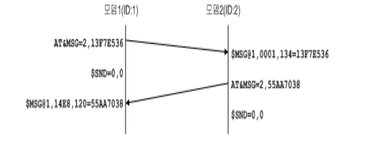
EZBee series Manual / Ver. 1.0 37
mode.
A modem 1 sends a message (0x13F7E53) to a modem 2. The
modem 2 received data from a sender having the ID=1, the short-
address=0x0001. The receiving sensitivity is 134 and the received
message is 0x13F7E536.
While, a modem 2 sends the message(0x55AA7038) to a modem 1.
The received data by a modem 1 is shown as 0x55AA7038 with a receiving
sensitivity 120.
7.3.2
7.3.27.3.2
7.3.2 Data transmission in
Data transmission inData transmission in
Data transmission in
Bypass
Bypass Bypass
Bypass mode
modemode
mode
In Bypass mode, all data inputted from a serial port can be transmitted
without any modification to a pointed modem. Accordingly, the Bypass
mode is suitable for transmitting all data to one specified modem in a PAN.
Followings are AT commands related to the Bypass mode
communication.

EZBee series Manual / Ver. 1.0 38
Command
Parameter Result Description
ATD <space><DstID>
OK
/
ERROR
/
FA
IL/NO_MEM
/NWK_STOP
Convert from ASCII mode to
Bypass mode
AT+DST
? <DstID> Read a receiver ID of the Bypass
mode
=<DstID> OK /ERROR Set a receiver ID of the Bypass
mode
+++ None OK Convert from Bypass mode to
ASCII mode
In Bypass mode, all data are transmitted to the assigned receiving
modem. Accordingly the ASCII or EBI mode is more suitable than the
Bypass mode when a receiving modem is changed frequently or data are
transmitted to group or broadcasted all modem joined in the network.
ATD command can omit the <DstID> parameter. In this case, data
are transmitted to a modem ID which was set by ‘ AT+DST’ or previous ATD
command.
Following diagram shows the example of data transmission in Bypass
mode.
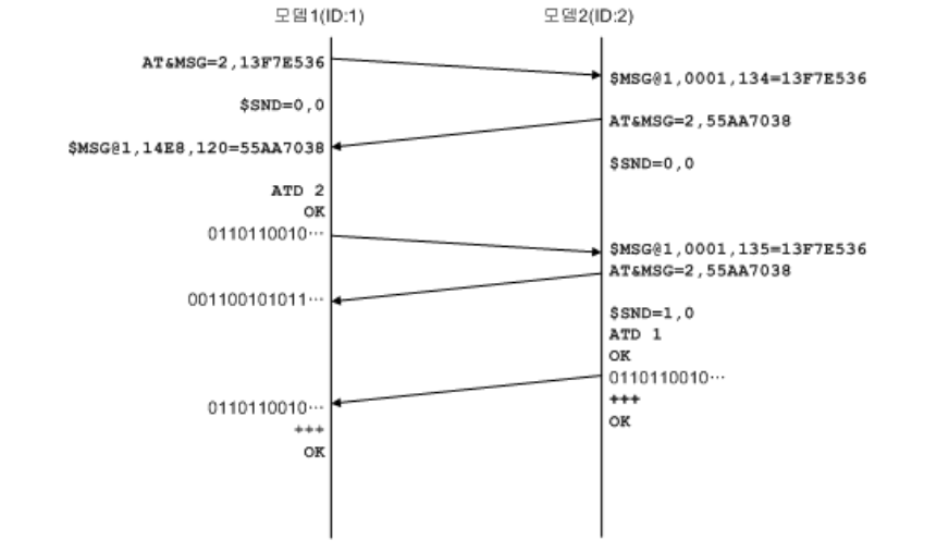
EZBee series Manual / Ver. 1.0 39
It is not necessary the receiver and sender have been set as same
communication mode. The communication mode is selected according to
the operating environment.
If a sender is set as Bypass mode and a receiver as ASCII mode, and
the sender sends a long message, the receiver can receive the message
as divided length of messages due to the size of internal buffer or
transmission delay.
For converting from the Bypass to ASCII mode, a string “ +++” should
be typed at least 300 [ msec] later after transmitting the final data. A
mode converting is succeeded if no characters are inputted during 300
[ msec] after inputting the string “ +++” . If any characters are inputted
within 300 [ msec] , it is considered as the transmitting data.

EZBee series Manual / Ver. 1.0 40
7.4
7.47.4
7.4 Reading a
Reading a Reading a
Reading a Short
ShortShort
Short-
--
- address
addressaddress
address
A 16 bit short- address assigned during the process of joining in the
PAN can be obtained by utilizing following AT commands. A short-
address is mainly used in practical communication instead of an extended
address.
Command
Parameter
Result Description
AT+SA? None <short address> Read a short-address assigned
AT+SA@ <DstID>?
OK
/
ERROR
/
N
WK_STOP
Check a short-address having a remote
modem ID <DstID>
If the short- address returned from a modem shows 0xFFFE, then it
means the short address is not assigned because the PAN is not started or
a modem is not joined in the PAN yet.
In case of a remote modem, it returns a following message when a
message transmission is succeeded.
Message
Parameter Description
$SA@ <DstID>=<SADDR>
Show a short-address <SADDR> of a remote
modem <DstID>
7.5
7.57.5
7.5
Reading an e
Reading an eReading an e
Reading an extended address
xtended addressxtended address
xtended address
Using following commands, the IEEE 64bit extended address of a
specific modem is readable.

EZBee series Manual / Ver. 1.0 41
Command
Parameter Result Description
AT+EA? None <extended address>
Read an extended address of a
current modem.
AT+EA@ <DstID>?
OK
/
ERROR
/
NWK
_STOP
Read an extended address of a
remote modem having <DstID>
In case of a remote modem, it returns a following message when a
message transmission is succeeded.
Message Parameter Description
$EA@ <DstID>=<EADDR>
Show an extended address <EADDR> of a remote
modem <DstID>.
7.6
7.67.6
7.6
Resetting a Modem
Resetting a Modem Resetting a Modem
Resetting a Modem
The command for modem resetting is shown as following.
Command
CommandCommand
Command
Parameter
ParameterParameter
Parameter
Result
ResultResult
Result
Description
DescriptionDescription
Description
ATZ
ATZATZ
ATZ
None $RESET
$RESET$RESET
$RESET
Software reset for a modem
7.7
7.77.7
7.7 Resetting a Network
Resetting a NetworkResetting a Network
Resetting a Network
In case of changing network parameters or joining again in the PAN,
the network status should be reset using following AT command.
Command Paramete
r
Result Description
ATNZ None $RESET Reset the network

EZBee series Manual / Ver. 1.0 42
7.8
7.87.8
7.8
Reading a modem version
Reading a modem versionReading a modem version
Reading a modem version
It is checked the firmware version of a modem using following AT
command.
Command
CommandCommand
Command
Parameter
ParameterParameter
Parameter
Result
ResultResult
Result
Description
DescriptionDescription
Description
ATV
ATVATV
ATV
None EZB300FV1.0
EZB300FV1.0EZB300FV1.0
EZB300FV1.0
EZBEE300 FFD version 1.0
EZB300RV1.0
EZB300RV1.0EZB300RV1.0
EZB300RV1.0
EZBEE300 RFD version 1.0
7.9
7.97.9
7.9
Reading a modem status
Reading a modem statusReading a modem status
Reading a modem status
It is checked the current status of a modem using following AT
command.
Command
CommandCommand
Command
Parameter
ParameterParameter
Parameter
Result
ResultResult
Result
Description
DescriptionDescription
Description
ATS
ATSATS
ATS
None
$NWK=STOP
$NWK=STOP$NWK=STOP
$NWK=STOP
Non- establishing a PAN or not
join in the PAN
$NWK=COORD
$NWK=COORD$NWK=COORD
$NWK=COORD
PAN is started and a modem set
as a coordinator in the PAN
$NWK=ROUTER
$NWK=ROUTER$NWK=ROUTER
$NWK=ROUTER,
,,
,<SADDR>
A modem is joined in the PAN as
a Router, and a short- address is
assigned as <SADDR>
7.10
7.107.10
7.10 GPIO
GPIO GPIO
GPIO control and setting
control and settingcontrol and setting
control and setting
The EZBee formats support the functionality to read GPIO and ADC of
remote modems. It can read 8 GPIO ports and 2 ADC channels having 10
bit resolution.

EZBee series Manual / Ver. 1.0 43
7.10.1
7.10.17.10.1
7.10.1 GPIO
GPIO GPIO
GPIO direction setting
direction settingdirection setting
direction setting
The GPIO direction of a local or remote modem can be set by utilizing
following AT commands.
Command
Parameter Result Description
AT+IOD? None <direction value>
Read the GPIO direction of a
local modem
AT+IOD= <value> <direction value>
Set the GPIO direction of a
local modem
AT+IOD@
<DstID>?
OK
Read the GPIO direction of a
remote modem.
<DstID>=<value>
Set the GPIO direction of a
remote modem
The format of GPIO is shown as following.
7(MSB) 6 5 4 3 2 1 0(LSB)
PORT7 PORT6 PORT5 PORT4 PORT3 PORT2 PORT1 PORT0
Effective value (
00
~
FF
)
If the bit value of a port is 1, then the port acts as the output port. If
the bit value of a port is 0, then the port acts as the input port.
In order to set the GPIO input/ output mode of a remote modem, the
value for accessing to a remote modem should be set as 1. Please refer
to a command ‘AT+RA’.
When the command for a remote modem is accomplished successfully,
a following event message is returned.
Message Parameter Description
$IOD@ <DstID>=<value> Return the GPIO input/output mode value of a
remote modem <DstID>

EZBee series Manual / Ver. 1.0 44
7.10.2
7.10.27.10.2
7.10.2 GPIO
GPIO GPIO
GPIO control
controlcontrol
control
For control or monitor GPIO of a local or remote modem, following AT
commands are utilized.
Command
Parameter Result Description
AT+IO? None <value> Read the GPIO status value of a local
modem
AT+IO= <value> <value> Set the GPIO status value of a local
modem
AT+IO@ <DstID>? OK Read the GPIO status value of a
remote modem
AT+IO@ <DstID>=<value>
OK Set the GPIO status value of a remote
modem
The format of GPIO is shown as following.
7(MSB)
6 5 4 3 2 1 0(LSB)
PORT7 PORT6 PORT5 PORT4 PORT3 PORT2 PORT1 PORT0
Effective value (
00
~
FF
)
When the bit value of each port is 1, it means the port voltage level
(status) is high. When the bit value is 0, the port voltage is low. It is
possible to set the bit of each port when the port is assigned as an output
port.
When the command for a remote modem is accomplished successfully,
a following event message is returned.
Message Parameter Description
$IO@ <DstID>=<value> Return the GPIO status value of a remote modem
<DstID>

EZBee series Manual / Ver. 1.0 45
7.10.3
7.10.37.10.3
7.10.3 ADC
ADC ADC
ADC reading
readingreading
reading
The status value of a local or remote modem can be checked by
following AT commands.
Command Parameter Result Description
AT+ADC? None < CH1>,<CH2> Read the ADC status value of a
local modem
AT+ADC@ <DstID>? OK Read the ADC status value of a
remote modem
The ADCs in EZBee modem are 2 channels having 10 bit resolution,
and operated based on 3.3V reference voltage.
The status value of the ADC is expressed as ASCII HEX format. For
example, if 1.25V and 2.5V are inputted onto channel 1 and channel 2,
respectively, the ADC status values are expressed as 060F and 0C1E.
When the command for a remote modem is accomplished successfully,
a following event message is returned.
.
Message Parameter Description
$ADC@ <DstID>=<CH1>,<CH2>
Return ADC status value of a remote modem
<DstID>
7.11
7.117.11
7.11 Remote control
Remote controlRemote control
Remote control
allowance setting
allowance settingallowance setting
allowance setting
In the EZBee formats, the allowance is selectable whether it make a
remote modem control the GPIO or change parameters of a local modem
in the PAN.

EZBee series Manual / Ver. 1.0 46
Command Parameter
Result Description
AT+RA? None 1 / 0 Check the current allowance assigned
AT+RA=
1
OK
Allow a remote control.
0 Does not allow a remote control
7.12
7.127.12
7.12 PAN
PAN PAN
PAN joining allowance setting
joining allowance settingjoining allowance setting
joining allowance setting
The
allowance for joining in PAN is selectable. The EZBee formats can
set a parameter which is a decision value for other modem to join in the
PAN via a local modem.
Command Parameter Result Description
AT+PMJ? None 1 / 0 Check the current allowance assigned
AT+PMJ=
1
OK
Allow for other modem to join the
PAN
0 Does not allow for other modem to
join the PAN
AT+PMJ@
<DstID>?
OK Check the current allowance or set the
allowance of a remote modem
<DstID>=<1/0>
When the command for a remote modem is accomplished successfully,
a following event message is returned.
Message Parameter Description
$PMJ@ <DstID>=<value> Return the allowance of a remote modem
<DstID>

EZBee series Manual / Ver. 1.0 47
8
88
8 EBI
EBI EBI
EBI Commands
CommandsCommands
Commands
8.1
8.18.1
8.1
EBI
EBIEBI
EBI
mode overview
mode overviewmode overview
mode overview
To provide more flexible communication method in EZBee formats, the
EBI (EZBee Binary Interface) communication mode is developed. In EBI
mode, the receiving modem can be assigned. Furthermore, the data are
transmitted to a specific group modems or to all modems in a PAN.
Following AT command is useful to enter EBI mode from ASCII mode.
Command
Parameter
Result Description
ATB None OK Convert a communication mode to EBI
8.2
8.28.2
8.2 EBI
EBI EBI
EBI mode communication
mode communicationmode communication
mode communication
In EBI mode, following packet is utilized for data transmission.
SOP Type ID Length DATA
1byte 1byte 1byte 1byte Variable length
The effective values of each field are summarized as:
Field Value Meaning
SOP 0x55 Start Of Packet
Type Refer EBI type Message type
ID 0~0xFF sender/receiver ID
Length 0~0x50 Data length
DATA - -

EZBee series Manual / Ver. 1.0 48
8.3
8.38.3
8.3 EBI
EBI EBI
EBI packet type
packet typepacket type
packet type
The packet type and its meanings are summarized as following.
Packet type(Mnemonic)
CODE
Meaning
EBI_TYPE_UNICAST_
MSG 0x10 Unicast message
EBI_TYPE_GROUP_M
SG 0x11 Group message
EBI_TYPE_BROAD_M
SG 0x12 Broadcast message
EBI_TYPE_ACK 0x80 Response according to message transmission
EBI_TYPE_IO_REQ 0x20 Set or check the GPIO status value of a local or
remote modem
EBI_TYPE_IO_ACK 0x21 Response according to EBI_TYPE_IO_REQ
EBI_TYPE_IOD_REQ 0x22 Set or check the GPIO input/output mode value of
a local or remote modem
EBI_TYPE_IOD_ACK 0x23 Response according to EBI_TYPE_IOD_REQ
EBI_TYPE_ADC_REQ 0x24 Request ADC status value of a local or remote
modem
EBI_TYPE_ADC_ACK 0x25 Response according to EBI_TYPE_ADC_REQ
EBI_TYPE_ESCAPE 0x55 Escape from EBI mode (convert to ASCII mode)
8.3.1
8.3.18.3.1
8.3.1 EBI_TYPE_UNICAST_MSG
EBI_TYPE_UNICAST_MSGEBI_TYPE_UNICAST_MSG
EBI_TYPE_UNICAST_MSG
Description Sending/receiving data to/from a specified modem in the PAN
Direction send/receive
Data length Variable data length
ID sender/receiver modem ID
8.3.2
8.3.28.3.2
8.3.2 EBI_TYPE_GROUP_MSG
EBI_TYPE_GROUP_MSGEBI_TYPE_GROUP_MSG
EBI_TYPE_GROUP_MSG
Description Sending/receiving data to/from a specified modem group in the PAN

EZBee series Manual / Ver. 1.0 49
Direction send/receive
Data length Variable data length
ID sender/receiver modem group ID
8.3.3
8.3.38.3.3
8.3.3 EBI_TYPE_BROAD_MSG
EBI_TYPE_BROAD_MSGEBI_TYPE_BROAD_MSG
EBI_TYPE_BROAD_MSG
Description Sending/receiving broadcast data in the PAN
Direction send/receive
Data length Variable data length
ID Broadcast ID (0xFF)
8.3.4
8.3.48.3.4
8.3.4 EBI_TYPE_ACK
EBI_TYPE_ACKEBI_TYPE_ACK
EBI_TYPE_ACK
Description Result of message transmission from a modem to the PAN
Direction receive
Data length 2
ID 0
Data format
Data formatData format
Data format:
::
:
Result TransID
1(byte) 1(byte)
Meaning
Meaning Meaning
Meaning :
::
:
Field Value Meaning
Result
0 Success
1 Format is not valid
2 Fail (internal error)
3 Fail to memory allocation
TransID
0~255 When succeeded, transaction ID of message

EZBee series Manual / Ver. 1.0 50
EBI_TYPE_ACK packet always returns ‘success’ for the broadcast or
group message transmission.
In unicast message transmission, if a short- address of a receiver
modem ID does not exist, the data are transmitted as a broadcast
message in order to fix the short- address problem. Accordingly, even the
modem having identical modem ID with a receiver does not exist in the
PAN, the transmission result can be returned as ‘success’ .
8.3.5
8.3.58.3.5
8.3.5 EBI_TYPE_IO_REQ
EBI_TYPE_IO_REQEBI_TYPE_IO_REQ
EBI_TYPE_IO_REQ
Description Request to check or set the GPIO status value of a local or remote
modem
Direction send
Data length 0 or 1
ID Local or remote ID
Data length and parameter
Data length and parameterData length and parameter
Data length and parameter:
::
:
Data length
Parameter Description
0 0 Request the current value of GPIO ports
1 0x00~0xFF Set the status value of GPIO ports
8.3.6
8.3.68.3.6
8.3.6 EBI_TYPE_IO_ACK
EBI_TYPE_IO_ACKEBI_TYPE_IO_ACK
EBI_TYPE_IO_ACK
Description Response according to EBI_TYPE_IO_REQ
Direction receive
Data length 1
ID A local or remote modem ID

EZBee series Manual / Ver. 1.0 51
Data length and parameter
Data length and parameterData length and parameter
Data length and parameter:
::
:
Value Description
0x00~0xFF Show the GPIO status value of a local or remote modem
8.3.7
8.3.78.3.7
8.3.7 EBI_TYPE_IOD_REQ
EBI_TYPE_IOD_REQEBI_TYPE_IOD_REQ
EBI_TYPE_IOD_REQ
Description Set a GPIO input/output mode, or request a current setting value of a
local or remote modem
Direction send
Data length 0 or 1
ID A local or remote modem ID
Data length and parameter
Data length and parameterData length and parameter
Data length and parameter
:
::
:
Data length
Parameter Description
0 None Request a setting value of the GPIO
input/output mode
1 0x00~0xFF Set the GPIO input/output mode
8.3.8
8.3.88.3.8
8.3.8 EBI_TYPE_IOD_ACK
EBI_TYPE_IOD_ACKEBI_TYPE_IOD_ACK
EBI_TYPE_IOD_ACK
Description Response according to EBI_TYPE_IO_REQ
Direction receive
Data length 1
ID A local or remote modem ID
Data length and parameter
Data length and parameterData length and parameter
Data length and parameter
:
::
:
Value Description
0x00~0xFF Show a setting value of the GPIO

EZBee series Manual / Ver. 1.0 52
8.3.9
8.3.98.3.9
8.3.9 EBI_TYPE_ADC_REQ
EBI_TYPE_ADC_REQEBI_TYPE_ADC_REQ
EBI_TYPE_ADC_REQ
Description Request the ADC status value of a local or remote
Direction send
Data length 0
ID A local or remote modem ID
8.3.10
8.3.108.3.10
8.3.10 EBI_TYPE_ADC_ACK
EBI_TYPE_ADC_ACKEBI_TYPE_ADC_ACK
EBI_TYPE_ADC_ACK
Description Response according to EBI_TYPE_ADC_REQ
Direction receive
Data length 4
ID A local or remote modem ID
Data format
Data formatData format
Data format:
::
:
Channel-1 value Channel-2 value
2 byte 2 byte
8.3.11
8.3.118.3.11
8.3.11 EBI_TYPE_ESCAPE
EBI_TYPE_ESCAPEEBI_TYPE_ESCAPE
EBI_TYPE_ESCAPE
Description Convert the communication mode from EBI to ASCII mode
Data length 0x55
ID 0x55
For successful communication mode conversion from EBI to ASCII
mode, 0x55555555, namely, string “ UUUU ” should be inputted to a
modem within 1 second.
EZBee series Manual / Ver. 1.0 53
Appendix
Appendix Appendix
Appendix
How to use
How to use How to use
How to use EZBee
EZBeeEZBee
EZBee
M100
M100 M100
M100
1.
1.1.
1. Setting
Setting Setting
Setting Serial
Serial Serial
Serial Port
PortPort
Port
1 Install the ‘FTDI USB to Serial’ driver on a user PC.
2 Connect a EZBee M100 to the user PC.
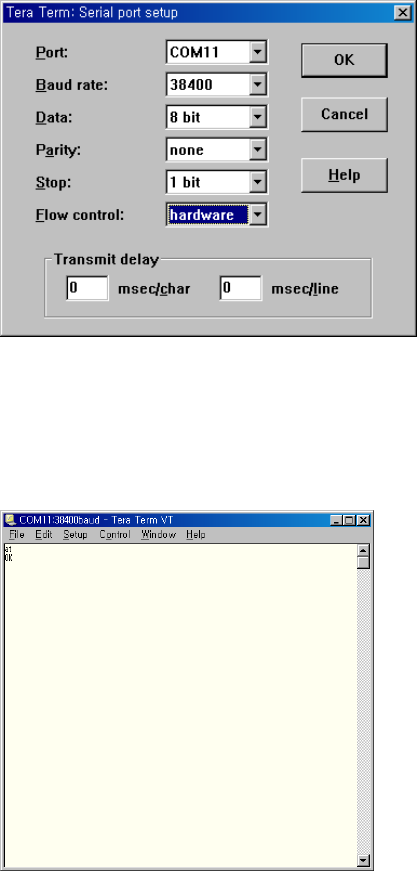
3 After running a terminal emulator such as Hyper Terminal or Tera
Term, set the parameters as followings.
※ Displaying parameters may be different from the PC environment.
4
44
4
If “
““
“OK
OKOK
OK”
””
” message is displayed on the terminal when “
““
“AT
ATAT
AT”
””
” command
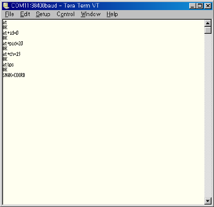
is typed, the EZBee M100 is installed successfully to a serial port.
EZBee series Manual / Ver. 1.0 54
2.
2. 2.
2. Start
Start Start
Start PAN
PAN PAN
PAN Network
NetworkNetwork
Network
For starting a PAN, type the AT commands related to a module ID, PAN
ID and channel number as shown in the following figure. The module ID
should be 0 for a coordinator setting. Finally type “
““
“AT&PS
AT&PSAT&PS
AT&PS”
””
”
to start the
PAN.
If the PAN is started successfully, “
““
“ $NWK=COORD
$NWK=COORD$NWK=COORD
$NWK=COORD ”
””
” message is
displayed. It means the EZBee M100 connected to a serial port is
assigned as a coordinator in the PAN.
The PAN ID and channel number can be assigned differently as user‘s
wish.
From now on, we call this terminal as a
Coordinator
Coordinator Coordinator
Coordinator Terminal
TerminalTerminal
Terminal
, and the
EZBee M100 connected to the coordinator terminal as a
Coordinator
CoordinatorCoordinator
Coordinator
Module
ModuleModule
Module
.
EZBee series Manual / Ver. 1.0 55
3.
3. 3.
3. Joining the
Joining the Joining the
Joining the PAN
PANPAN
PAN
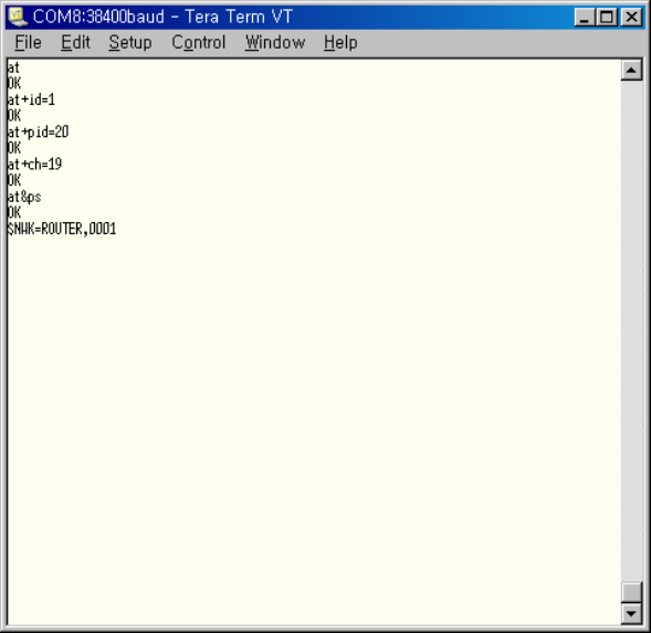
After running another terminal emulator, set the serial port and EZBee
M100 as shown in 1 and 2 steps above.
Then, type the AT commands related to a module ID, PAN ID and
channel number. In this moment, the module ID can be any number
except ‘0’. However, a PAN ID and channel number should be same
numbers as coordinator setting for joining in the PAN established already.
Finally type “
““
“AT&PS
AT&PSAT&PS
AT&PS”
””
”
for a new EZBee M100 to join in the PAN.
If the EZBee M100 is joined in the PAN successfully,
“
““
“$NWK=ROUTER
$NWK=ROUTER$NWK=ROUTER
$NWK=ROUTER,<SADDR>”
””
” message is displayed.
It means the EZBee M100 is assigned as a router in the PAN, and a
short- address of this EZBee router is assigned as <SADDR> by a
EZBee series Manual / Ver. 1.0 56
coordinator. In this example, a short- address of EZBEE module is
assigned as 0001
00010001
0001(hexadecimal).
Now, we call this terminal as a
Router
RouterRouter
Router
Terminal
TerminalTerminal
Terminal
, and the EZBee M100
connected to the coordinator terminal as a
Router
RouterRouter
Router
Module
ModuleModule
Module
.
4.
4. 4.
4. Testing message transmission in
Testing message transmission in Testing message transmission in
Testing message transmission in ASCII
ASCII ASCII
ASCII mode
modemode
mode
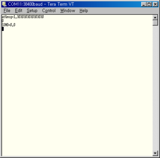
To transmit a message in ASCII mode, type a following command on a
coordinator terminal. “
““
“AT&MSG=
AT&MSG=AT&MSG=
AT&MSG=<DstID>,
,,
,<Msg>”
””
”
In here, DstID and Msg mean a receiver ID and a sending message,
respectively. The sending message should be prepared as ASCII
hexadecimal format. Following example shows that the receiver ID,
‘DstID’ is 1
11
1, and the sending message, ‘Msg’ is “
““
“3030303030303030
30303030303030303030303030303030
3030303030303030”
””
”.
When the command is completed successfully, firstly the Transaction ID

EZBee series Manual / Ver. 1.0 57
is returned. In here, Transaction ID ‘ 0’ is returned as shown in second
line of above example.
Furthermore, an event message related to the transmission result is
displayed as “
““
“$SND=
$SND=$SND=
$SND=<TransID>,
,,
,<Result>”
””
”.
..
.
<TransID> means a Transaction ID, 0
00
0 in this example, and <Result>
shows the transmission result, 0
00
0 in this example means the transmission is
succeeded. If failed, non- zero value is shown as <Result>.
Accordingly, the message is transmitted successfully; a following event
message related to the message arrival is displayed in a router terminal.
The format of an event message related to the message arrival is,
“
““
“$MSG@
$MSG@$MSG@
$MSG@<SrcID>,
,,
,<SrcSaddr>,
,,
,<LinkQuality>=
==
=<Msg>”
””
”
EZBee series Manual / Ver. 1.0 58
where, <SrcID> is a sender ID, <SrcSaddr> is a short- address of sender,
<LinkQuality> means a receiving sensitivity, and <Msg> means the
received message having same ASCII Hexadecimal format as sending
message
In this example, <SrcID> is 0
00
0,
and it means a sender is a coordinator.
<SrcSaddr> is 0000
00000000
0000. It shows that the short- address of the
coordinator is
always 0000. <LinkQuality> is 218
218218
218. The value of receiving sensitivity is
between 0 and 255. Finally, <Msg> is 3030303030303030
30303030303030303030303030303030
3030303030303030.
It means 8
byte data string having value of 0x30.
From now on, as a reverse transmission, a router terminal sends a
data to a coordinator terminal.
Using “
““
“ AT&MSG=
AT&MSG=AT&MSG=
AT&MSG=<DstID>,
,,
,<Msg> ”
””
”, a router sends a message to a
coordinator. In this case, <DstID> is set as 0 for a coordinator.

EZBee series Manual / Ver. 1.0 59
When the command is completed successfully, the event message
related to the message arrival is shown on a coordinator terminal.
EZBee series Manual / Ver. 1.0 60
5.
5. 5.
5. Testing message transmission in
Testing message transmission inTesting message transmission in
Testing message transmission in
Bypass
Bypass Bypass
Bypass mode
modemode
mode
1) Enter “
““
“ATD 1
ATD 1ATD 1
ATD 1”
””
”
command on a coordinator terminal, and “
““
“ATD 0
ATD 0ATD 0
ATD 0”
””
” on
a router terminal.
2) Type any keys on one terminal, and verify successful data
transmission on the other terminal.
3) To end Bypass mode, enter “
““
“+++
++++++
+++”
””
”
on each terminals.
6.
6. 6.
6. Testing Input/ output function of
Testing Input/output function of Testing Input/output function of
Testing Input/output function of EZBee
EZBeeEZBee
EZBee
M100
M100M100
M100
EZBee M100 supports total 8 ports of GPIO from DIO0 through DIO7
which are set or controlled by a local or remote modem of EZBee.
First, enter “
““
“AT+IOD?
AT+IOD?AT+IOD?
AT+IOD?”
””
” command on a coordinator terminal to check
the I/ O directions of local EZBee M100. In this example, the return value
shows “
““
“00
0000
00”
””
”, it means all I/ O ports are assigned as input ports.
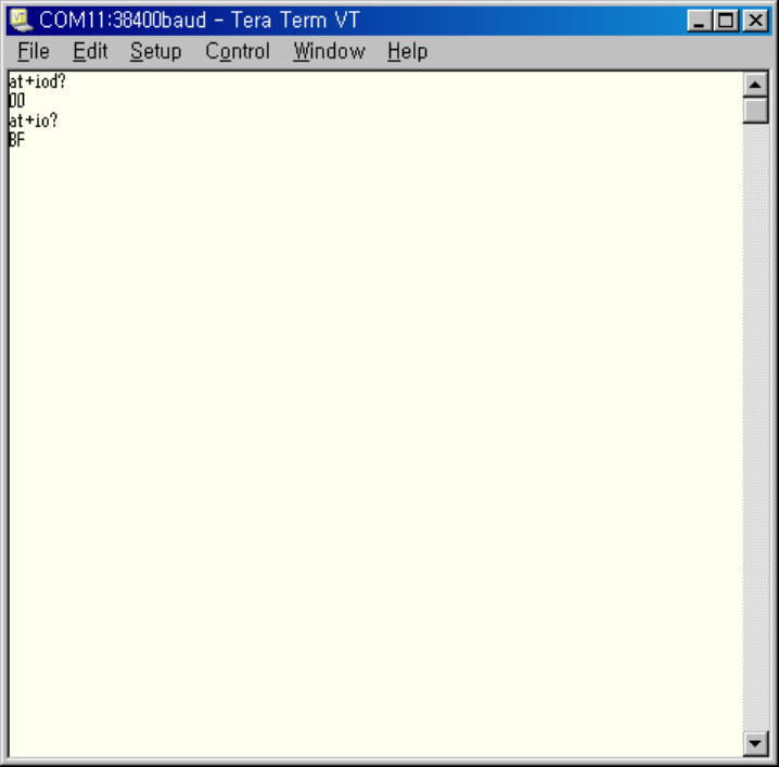
EZBee series Manual / Ver. 1.0 61
Next,
enter
“
““
“AT+IO?
AT+IO?AT+IO?
AT+IO?”
””
”
command in order to read the input value of a
current I/ O ports. The return value is “
““
“BF
BFBF
BF”
””
”, it is interpreted that DIO6 is 0
00
0,
the others are all 1
11
1.
During pushing DIO3 of a coordinator module, enter “
““
“ AT+IO?
AT+IO?AT+IO?
AT+IO?”
””
”
on
coordinator terminal again.

EZBee series Manual / Ver. 1.0 62
The return value is changed to “
““
“B7
B7B7
B7”
””
”. It means the input of
DIO3 is
changed from 1 to 0.
Now, enter “
““
“AT+IOD=FF
AT+IOD=FFAT+IOD=FF
AT+IOD=FF”
””
” command on a coordinator terminal. The
GPIO I/ O direction is changed, thereby all ports acts as output ports. If
command is completed successfully, the direction value of input/ output
is displayed as shown in a figure.
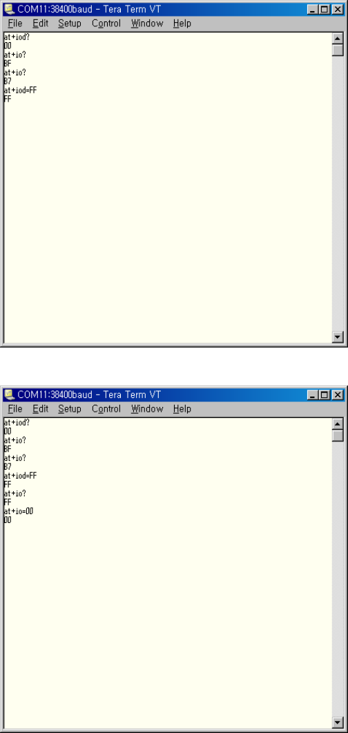
EZBee series Manual / Ver. 1.0 63
In this moment, enter “
““
“AT+IO=00
AT+IO=00AT+IO=00
AT+IO=00”
””
” command again.
You can see that DIO0 and DIO1 LED in the coordinator module are
turning ON.
Using similar philosophy, the GPIO of a remote modem is able to set
and control.
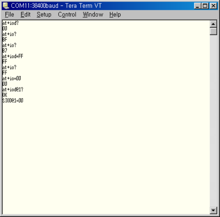
EZBee series Manual / Ver. 1.0 64
Enter “
““
“ AT+IOD@1?
AT+IOD@1?AT+IOD@1?
AT+IOD@1? ”
””
” command on a coordinator and read GPIO
input/ output status.
When the command is completed successfully, the response message,
“
““
“$IOD@1=00
$IOD@1=00$IOD@1=00
$IOD@1=00”
””
”
is displayed, which means all GPIO of a router is set as
inputs.
To read GPIO input status value of a router module, enter “
““
“AT+IO@1?
AT+IO@1?AT+IO@1?
AT+IO@1?”
””
”
on a coordinator terminal. If the command is completed successfully, the
response message such as “
““
“$IO@1=BF
$IO@1=BF$IO@1=BF
$IO@1=BF”
””
”
is outputted. It means the input
value of DIO6 is 0 and the others of GPIO are 1.

EZBee series Manual / Ver. 1.0 65
Enter “
““
“AT+IO@1?
AT+IO@1?AT+IO@1?
AT+IO@1?”
””
”
on a coordinator terminal while the button of DIO3
is pushed. When the command is completed successfully, “
““
“$IO@1=B7
$IO@1=B7$IO@1=B7
$IO@1=B7”
””
”
message is outputted, and it means the input value of DIO3 is changed to
0.
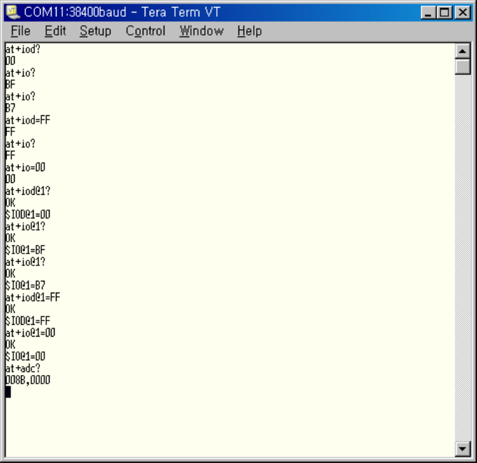
EZBee series Manual / Ver. 1.0 66
7.
7. 7.
7. Testing ADC of
Testing ADC of Testing ADC of
Testing ADC of EZBee
EZBeeEZBee
EZBee
M100
M100M100
M100
EZBee- M100 provides 2 channel ADC having 10- bit resolution and is
possible to read the ADC value of a local or remote modem.
Enter “
““
“AT+ADC?
AT+ADC?AT+ADC?
AT+ADC?”
””
” command for reading ADC value of a coordinator
module.
When the command is completed successfully, the value of
“
““
“<CH1>,
,,
,<CH2>” are displayed as shown in above figure. In this example,
the channel values of ADC are 008B
008B008B
008B for <CH1> and 0000
00000000
0000
for <CH2>.
In similar manner, the ADC value of a remote modem is able to read.
To read the ADC value of a router module, enter “
““
“ AT+ADC@1?
AT+ADC@1?AT+ADC@1?
AT+ADC@1? ”
””
”
command on a coordinator terminal.
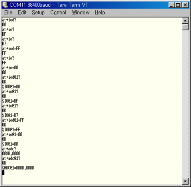
EZBee series Manual / Ver. 1.0 67
When the command is completed successfully, the result message such
as “
““
“$ADC@
$ADC@$ADC@
$ADC@<SrcID>=
==
=<CH1>,
,,
,<CH2>”
””
”
is displayed. In here,
<SrcID> is a
remote modem ID, <CH1> and <CH2> means the ADC channel value of
each modem. In this example, <SrcID> is 1
11
1, <CH1> and <CH2> are 0000
00000000
0000
and 0000
00000000
0000, respectively.
※ The usage of EZBee U100 and EZBee L100 is same as EZBee M100.
※ In data transmission process between EZBee formats, the transmitting
data loss may be happened due to the characteristics of RF signal and
environment of RF transmission.

FCC Information
This device complies with Part 15 of the FCC Results. Operation is subject to the following two
conditions :
(1) This Device may not cause harmful interface, and
(2) This Device must accept any interference received, including interference that
may cause undesired operation.
WARNING
Changes or modifications not expressly approved by the manufacturer could void the user’s
authority to operate the equipment.
CAUTION : Exposure to Radio Frequency Radiation.
To comply with FCC’s RF exposure limits for general population / uncontrolled exposure, the
antenna(s) used for this transmitter must be installed to provide a separation distance of at
least 20cm from all persons and must not be co-located or operating in conjunction with any
other antenna or transmitter.
Note : This equipment has been tested and found to comply with the limits for CLASS
B digital device, pursuant to Part 15 FCC Rules. These limits are designed to provide
reasonable protection against harmful interference when the equipment is operated in
a commercial environment. This equipment generates, uses and can radiate radio
frequency energy and, if not installed and used in accordance with the instructions,
may cause harmful interference to radio communications.
However, there is no guarantee that interference will not occur in a particular
installation. If this equipment does cause harmful interference to radio or television
reception, which can be determined by turning the equipment off and on, the user is
encouraged to try correct the interference by one or more of the following measures ;
1.1. Reorient or relocate the receiving antenna.
1.2. Increase the separation between the equipment and receiver.
1.3. Connect the equipment into an outlet on a circuit different from that to
which receiver is connected.
1.4. Consult the dealer or experienced radio/TV technician for help.