ERG Transit Systems MCR200 Tag Reader Module User Manual APPENDIX B
ERG Transit Systems Tag Reader Module APPENDIX B
User Manual

FCC ID: Q47-MCR200 Report No. T40452F Appendix K Page 1 of 18
APPENDIX K
OF
TEST REPORT T40452F
USER MANUAL
FCC ID: Q47-MCR200
Manufacturer: ERG Transit Systems
Test Sample: Contactless Smart Card Reader
Model: MCR200
Serial No: 0318111546
Date: 29th July 2004
EMC Technologies Pty Ltd
A.C.N. 057 105 549
16/6 Gladstone Rd
Castle Hill, NSW 2154
Ph: + 612 9899 4599
Fax: + 612 9899 4019
email: syd@emctech.com.au
HTTP: www.emctech.com.au
Device Product Group
MCR200 User Manual
Document No: DPG-00144 Category: 431 Revision: 7
ERG
Approvals Author Hardware Manager
Name: Dan Zorde Gino Bertino
Signature:
Date:
This material is confidential to ERG and may not be disclosed in whole or in part to any third party nor used in any
manner whatsoever other than for the purposes expressly consented to by ERG in writing.
This material is also copyright and may not be reproduced, stored in a retrieval system or transmitted in any form or
by any means in whole or in part without the express written consent of ERG.

Device Product Group Security Level 3 MCR200 User Manual
DPG-00144 ERG Confidential © ERG 2004 Page 2 of 17
Revision 7 / 5 July 2004
Document History
Revision Revision
Date Description Author
1.0 10 March 03 First release Gino Bertino
2.0 04 April 03 Revised FCC compliance statement Gino Bertino
3.0 05 May 03 Includes reference to correct FCC ID code Gino Bertino
4.0 23 Jun 03 Removed blank second page Gino Bertino
5.0 2 July 03 Change to Section 4.4 ferrite statement Dan Zorde
6.0 7 May 04 Updated for Rev2 card reader with shield Dan Zorde
7.0 5 July 04 Shield update Dan Zorde

Device Product Group Security Level 3 MCR200 User Manual
DPG-00144 ERG Confidential © ERG 2004 Page 3 of 17
Revision 7 / 5 July 2004
Table of Contents
1 INTRODUCTION .......................................................................................................................................5
1.1 PURPOSE.............................................................................................................................................5
1.2 SCOPE.................................................................................................................................................5
1.3 TERMINOLOGY ..................................................................................................................................... 5
2 OVERVIEW OF THE MCR ........................................................................................................................6
3 MODULE ARCHITECTURE......................................................................................................................8
3.1 ELECTRICAL SPECIFICATION.................................................................................................................. 8
3.2 HOST SERIAL COMMUNICATION INTERFACE ............................................................................................ 8
3.3 POWER SUPPLY ...................................................................................................................................9
3.4 RF CONTROLLER..................................................................................................................................9
3.4.1 Transmitter................................................................................................................................. 9
3.4.2 Receiver..................................................................................................................................... 9
3.4.3 Card Interface ............................................................................................................................9
4 HOST INTERFACE CONNECTIONS......................................................................................................10
4.1 SUPPORTED ELECTRICAL INTERFACES ................................................................................................ 10
4.2 HOST INTERFACE CONNECTOR ...........................................................................................................10
4.3 INTERFACE CONNECTIONS..................................................................................................................10
4.4 INTERCONNECTING CABLE................................................................................................................... 11
5 MECHANICAL SPECIFICATION............................................................................................................12
5.1 PHYSICAL DIMENSIONS.......................................................................................................................12
5.1.1 Size .......................................................................................................................................... 12
5.1.2 Mounting Holes........................................................................................................................13
5.2 INDIVIDUAL COMPONENT DIMENSIONS .................................................................................................14
5.2.1 Control Board Dimensions....................................................................................................... 14
5.2.2 Antenna Dimensions................................................................................................................ 15
6 MOUNTING GUIDELINES ......................................................................................................................16
7 ANTENNA TUNING.................................................................................................................................17
List of Tables
TABLE 1: TERMINOLOGY.......................................................................................................................................5
TABLE 2: SERIAL INTERFACE CONNECTIONS........................................................................................................10
TABLE 3: PHYSICAL DIMENSIONS ........................................................................................................................12
List of Figures
FIGURE 1: MCR200 OEM MODULE .....................................................................................................................6
FIGURE 2: MCR200 OEM MODULE - OPERATION................................................................................................. 7
FIGURE 3: MODULE ARCHITECTURE ...................................................................................................................... 8
FIGURE 4: INTERCONNECTING HOST CABLE ........................................................................................................11
FIGURE 5: TYPICAL STACKING ARRANGEMENT ..................................................................................................... 12
FIGURE 6: TYPICAL PHYSICAL ENVELOPE.............................................................................................................13
FIGURE 7: CONTROL BOARD DIMENSIONS........................................................................................................... 14
FIGURE 8: ANTENNA DIMENSIONS ....................................................................................................................... 15
FIGURE 9: CLEARANCE BETWEEN ANTENNA AND METALLIC OBJECTS..................................................................... 16
FIGURE 10: LOCATION OF TUNING CAPACITOR CV1 .............................................................................................17

Device Product Group Security Level 3 MCR200 User Manual
DPG-00144 ERG Confidential © ERG 2004 Page 4 of 17
Revision 7 / 5 July 2004
FCC Compliance Statement
This device complies with Part 15 of the FCC rules. Operation is subject to the following two
conditions: (1) This device may not cause harmful interference, and (2) this device must
accept any interference received, including interference that may cause undesired operation.
This equipment has been tested and found to comply with the limits for a Class B digital
device, pursuant to Part 15 of the FCC Rules. These limits are designed to provide
reasonable protection against harmful interference in a residential installation. This
equipment generates, uses and can radiate radio frequency energy and, if not installed and
used in accordance with the instructions, may cause harmful interference to radio
communications. However, there is no guarantee that interference will not occur in a
particular installation. If this equipment does cause harmful interference to radio or
television reception, which can be determined by turning the equipment off and on, the user
is encourage to try to correct the interference by one or more of the following measures:
• Reorient or relocate the receiving antenna.
• Increase the separation between the equipment and receiver.
• Connect the equipment into an outlet on a circuit different from that to which the receiver
is connected.
• Consult the dealer or an experienced radio/TV technician for help.
The MCR200 was submitted and a grant of authorisation received from the FCC as a
modular device under the intentional radiator requirements of part 15, Subpart C.
The party that incorporates the MCR200 into their product is responsible for verification of
the emissions produced by the final product and must adhere to the limits specified in the
code of Federal Regulations 47, Part 15, Subpart B.
Furthermore, a label must be applied on the exterior of the final product, referring to this
enclosed module, which shall state, “Contains FCC ID: Q47-MCR200” or “Contains
Transmitter Module FCC ID: Q47-MCR200”.
Notice: When an AC to DC power source is used to supply power to the integrated
equipment, the final equipment will also have to comply with the AC line conducted
emissions according to FCC Part 15, Subpart B.
Warning: Any changes or modifications not expressively approved by ERG Transit
Systems could void the user's authority to operate this equipment
Device Product Group Security Level 3 MCR200 User Manual
DPG-00144 ERG Confidential © ERG 2004 Page 5 of 17
Revision 7 / 5 July 2004
1 Introduction
1.1 Purpose
The purpose of this document is to provide summary technical details of the electrical
interface and physical characteristic of the Multiprotocol Card Reader (MCR200). It is
intended for use by third party developers wanting to integrate the MCR200 OEM Module
into new or existing products.
1.2 Scope
This manual is intended for use by third party developers and integrators familiar with similar
type of equipment. This manual contains technical information sufficient to give technical
personnel an operational understanding of the MCR200.
1.3 Terminology
The following table contains a list of Equipment Terminology and their meanings.
Table 1: Terminology
Term Definition
A Amp(s), Ampere(s)
ASK Amplitude Shift Keying
bps Bits per second
BPSK Binary Phased Shift Keying
CMOS Complementary Metal-Oxide Semiconductor
CPU Central Processing Unit (microprocessor)
CSC Contact-less Smart Card
Host A processing unit communicating directly with and housing the
MCR200.
EIA Electronic Industry Association
EMC Electromagnetic Compatibility
GND Ground – negative supply
Hz Hertz, cycles per second
IEC International Electrotechnical Commission
ISO International Standards Organisation
MCR Multiprotocol Card Reader
mm millimetre(s)
NRZ-L Non-return to zero - level
OOK On-Off keying
PCB Printed Circuit Board
s second(s)
TIA Telecommunications Industry Association
Device Product Group Security Level 3 MCR200 User Manual
DPG-00144 ERG Confidential © ERG 2004 Page 6 of 17
Revision 7 / 5 July 2004
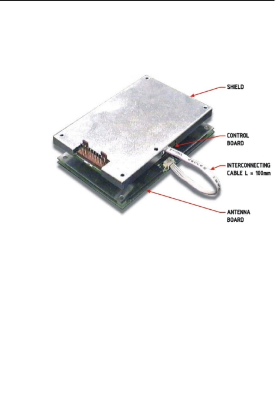
2 Overview of the MCR
The MCR200 OEM Module is an easy-to-use, economical means of introducing contact-less
smart card capability into a host. Figure 1 contains a picture of the MCR200 OEM Module.
Section 3 provides an overview of the module architecture. Section 4 provides a description
of the interface connector and pins. Section 5 provides dimensional details, section 6
describes how the MCR200 is to be mounted inside the host and Section 7 describes the
final tuning procedure.
Figure 1: MCR200 OEM Module
The MCR200 OEM module is a compact contact-less reader, which enables developers to
rapidly add contact-less functionality to new or existing products.
Each MCR200 consists of a Control Board and Antenna Board; this set is tuned and tested
at the factory prior to shipment. Each set is shipped with a 100 mm interconnecting cable as
shown in Figure 1.
Device Product Group Security Level 3 MCR200 User Manual
DPG-00144 ERG Confidential © ERG 2004 Page 7 of 17
Revision 7 / 5 July 2004
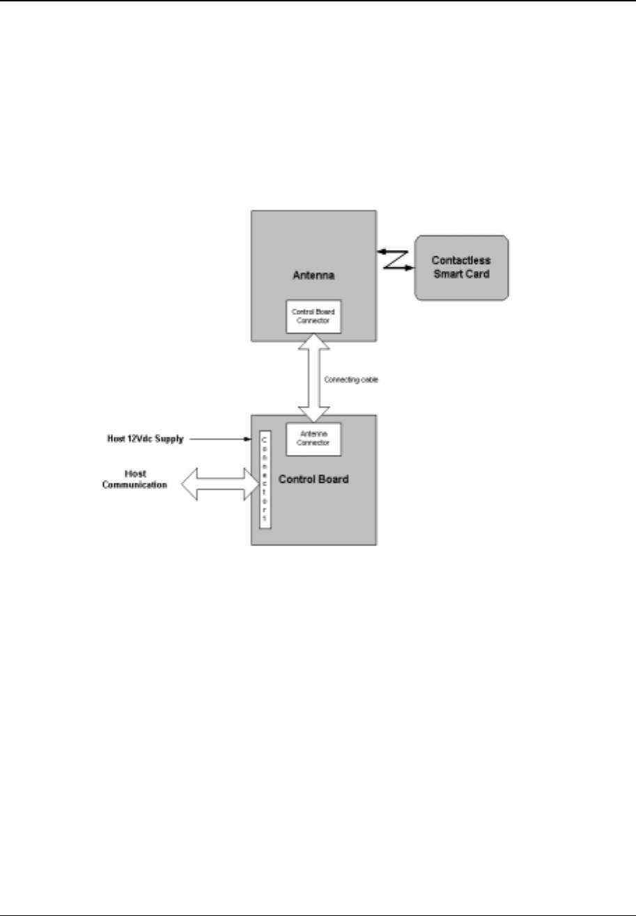
The MCR200 serves as the data communications link between customer smart cards and
the host in which the MCR200 is installed.
For MCR-to-Card communications, the Control Board receives data signals from the host. It
then transmits the data signals via RF to a smart card held within reading distance of the
MCR200’s Antenna Board. For Card-to-MCR communications, RF data signals from the
smart card are received by the Control Board via the Antenna Board where they are sent to
the host via connector 1 located on the Control Board. Figure 2 contains a block diagram
that illustrates the MCR200 mode of operation.
Figure 2: MCR200 OEM Module - Operation
Device Product Group Security Level 3 MCR200 User Manual
DPG-00144 ERG Confidential © ERG 2004 Page 8 of 17
Revision 7 / 5 July 2004
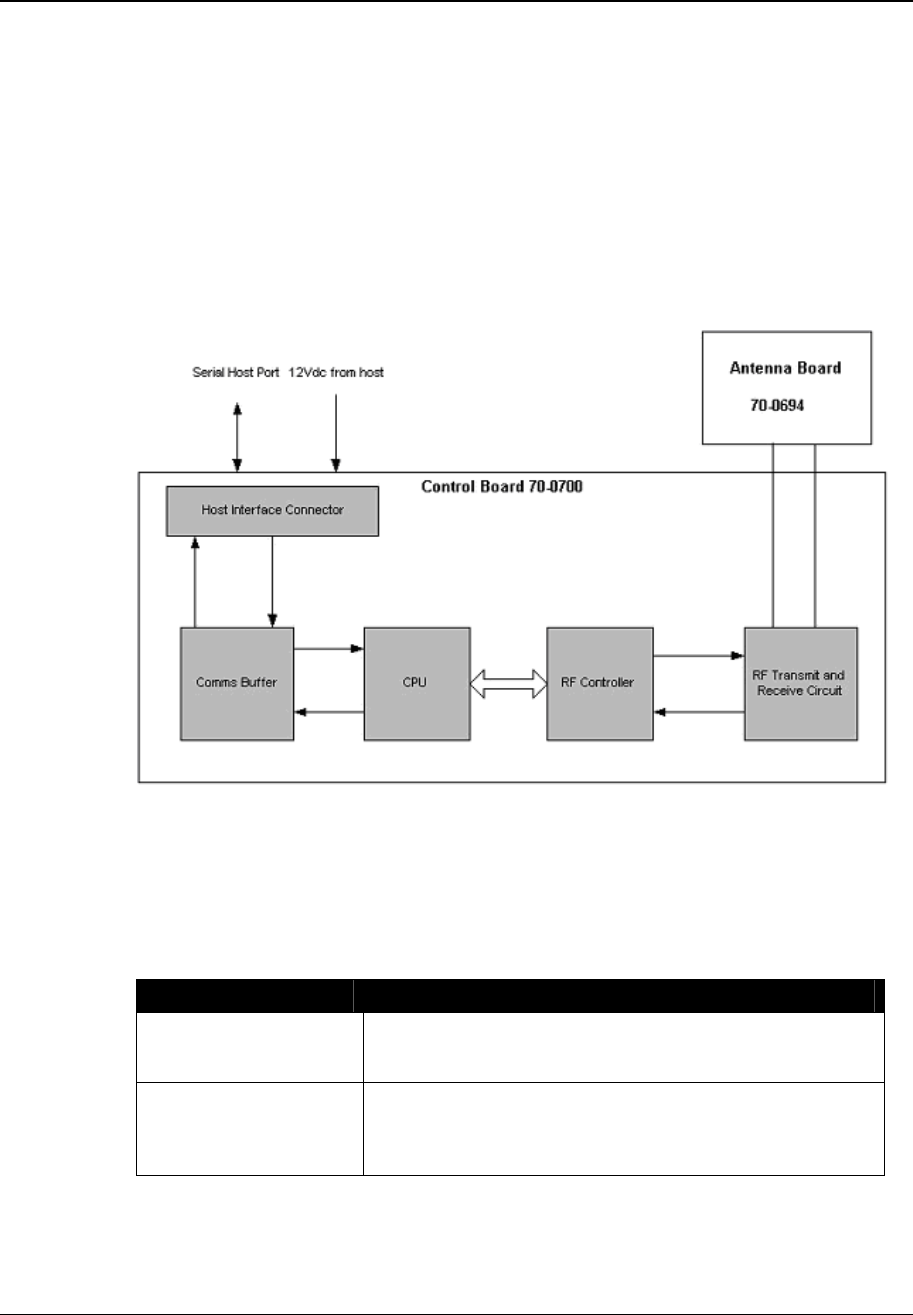
3 Module architecture
The Control Board contains a microprocessor, non-volatile memory, and radio frequency
transmitting and receiving circuitry. This board communicates with smart cards via a RF link
provided by the Antenna Board, and to the terminal via a TIA/EIA-485 or TIA/EIA-232 serial
protocol.
The Antenna Board consists of a printed circuit board with copper traces forming the
transmit and receive antenna. The board is attached to a ferrite plate and a metal back plate
that serves as a ground plane.
The module architecture is illustrated in Figure 3.
Figure 3: Module Architecture
3.1 Electrical specification
3.2 Host serial communication interface
Item Description
MCR to Host
communication interface Serial
TIA/EIA-232F and TIA/EIA-422 full duplex.
MCR to host baud rate Serial
9600bps, 19.2 Kbps, 38.4 Kbps, 57.6 Kbps, and 115.2
Kbps.
Device Product Group Security Level 3 MCR200 User Manual
DPG-00144 ERG Confidential © ERG 2004 Page 9 of 17
Revision 7 / 5 July 2004
3.3 Power Supply
The MCR200 OEM module derives power directly from the host. After supply power is
applied to the MCR200, the MCR200 will be operational in less than 1.2 seconds.
Item Description
Supply voltage 12Vdc +10%/-5%, with ripple of less than 50mV peak-peak.
Supply current Maximum 300 mA, typical 150 mA
Input power
requirements Maximum 3.60 Watts
3.4 RF controller
The standards supported by the RF controller are ISO/IEC 14443 Type A, ISO/IEC 14443
Type B and Mifare Standard.
3.4.1 Transmitter
The MCR200 transmitter complies with the following specifications:
Item Description
Carrier Frequency 13.56 MHz + 7 kHz (ISO/IEC 14443-2:2001, 6.1)
Modulation Rise and
Fall Time < 2.0 µsec (ISO/IEC 14443-2:2001, 8.1.2 and 9.1.2)
ASK Modulation 100% Modified Miller (ISO/IEC 14443-2:2001, 7 and 8)
8%-14% NRZ (ISO/IEC 14443-2:2001, 7 and 9)
3.4.2 Receiver
The MCR200 receiver complies with the following specifications:
Item Description
Carrier Frequency 13.56 MHz
Subcarrier
Frequency 847.5 kHz (ISO/IEC 14443-2:2001, 7, 8 and 9)
Subcarrier Data OOK Manchester (ISO/IEC 14443-3:2001 7 and 8)
BPSK NRZ-L (ISO/IEC 14443-2:2001, 7 and 9)
3.4.3 Card Interface
The MCR200 module supports contact-less smart cards conforming to the following signal
interface protocols:
• ISO/IEC 14443 Type A.
• ISO/IEC 14443 Type B.

Device Product Group Security Level 3 MCR200 User Manual
DPG-00144 ERG Confidential © ERG 2004 Page 10 of 17
Revision 7 / 5 July 2004
4 Host Interface Connections
4.1 Supported Electrical Interfaces
The serial interface between the Host and MCR supports both:
• TIA/EIA-485, half duplex
• TIA/EIA-232-F
The MCR200 is connected to the host via a 10-pin connector located on the Control Board.
The interconnection between the host and the MCR200 may be achieved using an
interconnecting cable as shown in Figure 4.
The default terminal to CAD communication speed is 115,200 bps. Other communication
speeds are available.
4.2 Host Interface Connector
The MCR200 interface connector mates with a straight connector.
Straight connector: Molex #22-01-2105 or equivalent
4.3 Interface Connections
Pin Designation Signal Level Function
1 Reset CMOS logic Can be used to reset the MCR.
2 GND Ground Ground (Power Supply negative)
3 +12V +12Vdc Power Supply positive
4 Rx- TIA/EIA-485 -ve Serial data from Host to MCR
5 Rx+ TIA/EIA-485 +ve Serial data from Host to MCR
6 Tx- TIA/EIA-485 -ve Serial data from MCR to Host
7 Tx+ TIA/EIA-485 +ve Serial data from MCR to Host
8 TxD TIA/EIA-232 Serial data from MCR to Host
9 GND Ground Ground (Power supply negative)
10 RxD TIA/EIA-232 Serial data from Host to MCR
Table 2: Serial Interface Connections
If the Host provides a hardware reset, it will be a logic-level, active-low signal with a
minimum pulse width of 10 microseconds.
Device Product Group Security Level 3 MCR200 User Manual
DPG-00144 ERG Confidential © ERG 2004 Page 11 of 17
Revision 7 / 5 July 2004
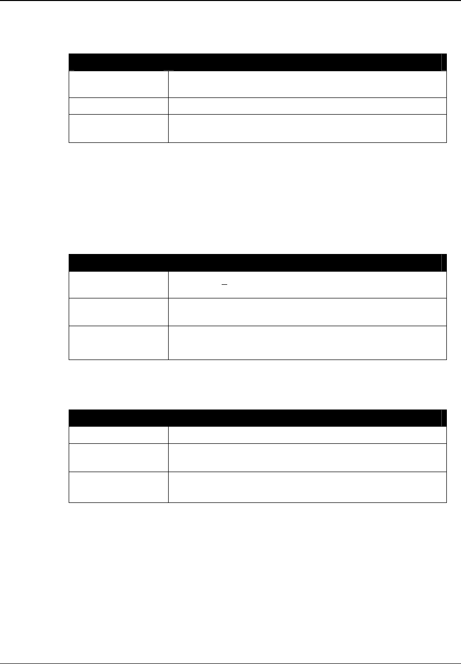
4.4 Interconnecting cable
Figure 4: Interconnecting Host Cable
Ferrite bead, Steward #28B1122-100, must be fitted as shown in Figure 4, on the DC power
cable connecting to the MCR200.
Device Product Group Security Level 3 MCR200 User Manual
DPG-00144 ERG Confidential © ERG 2004 Page 12 of 17
Revision 7 / 5 July 2004
5 Mechanical specification
5.1 Physical Dimensions
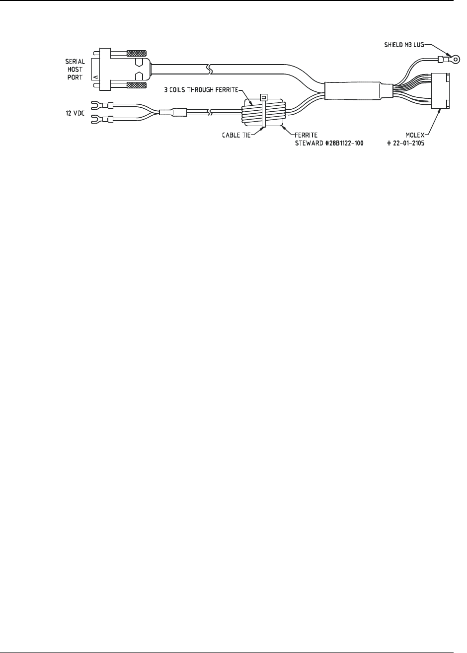
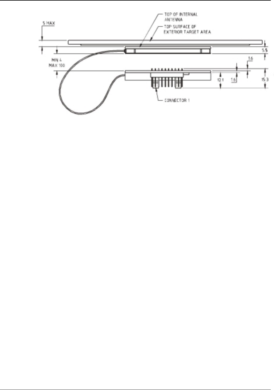
The two components that form the MCR200 (Control and Antenna boards) are organised so
that they can be physically separated by a distance of up to 100 mm, and connected via a
connecting cable. It is possible to stack the two components into a thickness of 24.5 mm.
Figure 5: Typical stacking arrangement
5.1.1 Size
The guaranteed Reader volumetric envelope is shown in Figure 6. It is acceptable to mount
the MCR in a larger volumetric envelope if space is available.
The Control Board and Antenna have the following dimensions:
Length
(mm) Width (mm) Height (mm) Tolerance (mm)
Control Board 104 67 15.5 ± 0.5
Antenna Board 104
67 5.5 ± 0.5
Table 3: Physical Dimensions
Device Product Group Security Level 3 MCR200 User Manual
DPG-00144 ERG Confidential © ERG 2004 Page 13 of 17
Revision 7 / 5 July 2004
Figure 6: Typical physical envelope
5.1.2 Mounting Holes
All mounting holes are M3.2. The mounting holes are aligned and may be used with screws
and plastic spacers to secure the MCR200 inside the product. The 100 mm cable allows the
Control Board and Antenna Board to be separated to accommodate different mounting
scenarios. For instance, the boards could be stacked, mounted side by side or mounted on
an angle.
Spacers between the shield and control pcb, ensure the shield remains fixed to the control
pcb, and eliminates shield deformation during assembly into the final product.
Device Product Group Security Level 3 MCR200 User Manual
DPG-00144 ERG Confidential © ERG 2004 Page 14 of 17
Revision 7 / 5 July 2004
5.2 Individual Component Dimensions
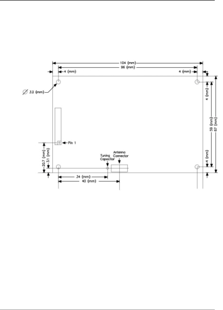
5.2.1 Control Board Dimensions
The Control Board dimensions, and the placement of the connectors, conform to those
shown in Figure 7.
Figure 7: Control Board Dimensions
Device Product Group Security Level 3 MCR200 User Manual
DPG-00144 ERG Confidential © ERG 2004 Page 15 of 17
Revision 7 / 5 July 2004
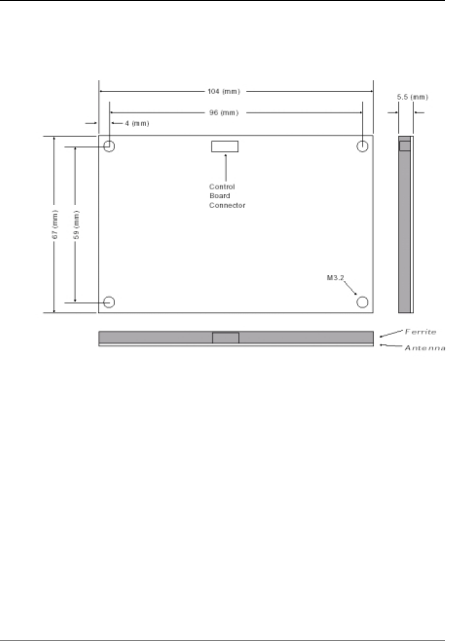
5.2.2 Antenna Dimensions
The Antenna conforms to the dimensions shown in Figure 8. The Antenna thickness is 5.5
mm.
Figure 8: Antenna Dimensions
Device Product Group Security Level 3 MCR200 User Manual
DPG-00144 ERG Confidential © ERG 2004 Page 16 of 17
Revision 7 / 5 July 2004
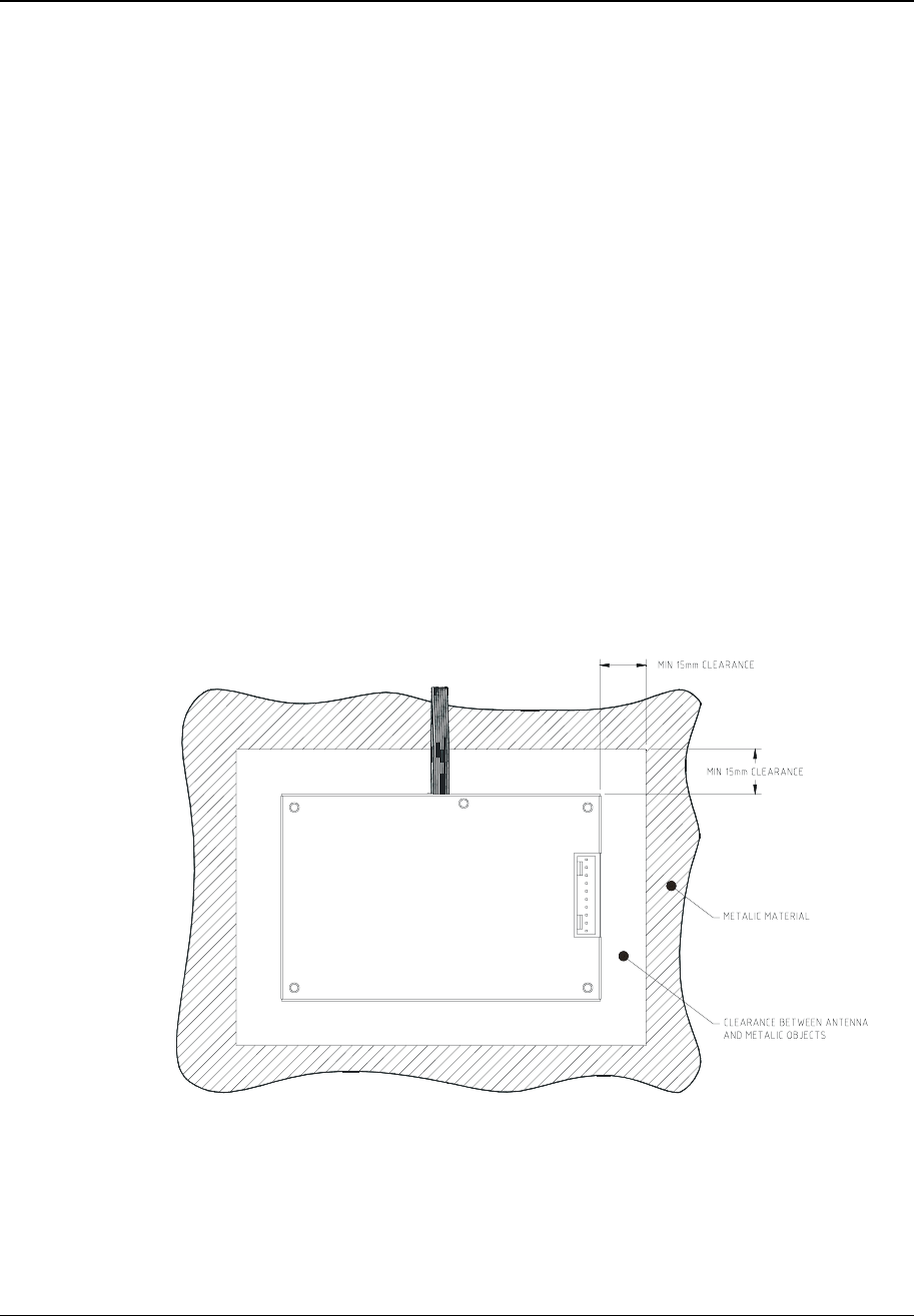
6 Mounting guidelines
These guidelines are intended to assist product designers maximise the operation of the
MCR200 in products:
• Ensure that any metalwork and/or EMC coatings are at least 15 mm away from the sides
of the antenna board in a horizontal plane and more than 5 mm below the vertical plane.
Designers should use the maximum possible clearance.
• The top of the antenna PCB (non-metallic side) must face towards the card reading
surface of the terminal and be less than 5 mm from the top surface. Any increase in this
distance will impact the Reader performance, and may result in the product being unable
to meet the project’s specifications, particularly the operating distance.
• The surface of the target area, which is directly above the Antenna Board, must be a
non-metallic surface such as plastic and be free of any metallic particles.
• It should be possible to tune the reader using the tuning capacitor shown in Figure 10
while leaving the antenna PCB fixed to the product. The product should ideally be
designed to permit re-tuning once the MCR200 is fitted.
• Removal of the shield to mount the MCR200 in ways not otherwise possible will breach
the FCC regulations and void all warranty.
• Ensure that the cable interconnecting the Antenna Board to the Control Board is located
away from metal surfaces and that the cable is fixed to avoid movement. Any movement
may degrade the reader performance, as the cable is an active part of the antenna
system.
• Ideally, both the control and antenna PCBs should be kept together as a unit.
Figure 9: Clearance between antenna and metallic objects.
Device Product Group Security Level 3 MCR200 User Manual
DPG-00144 ERG Confidential © ERG 2004 Page 17 of 17
Revision 7 / 5 July 2004
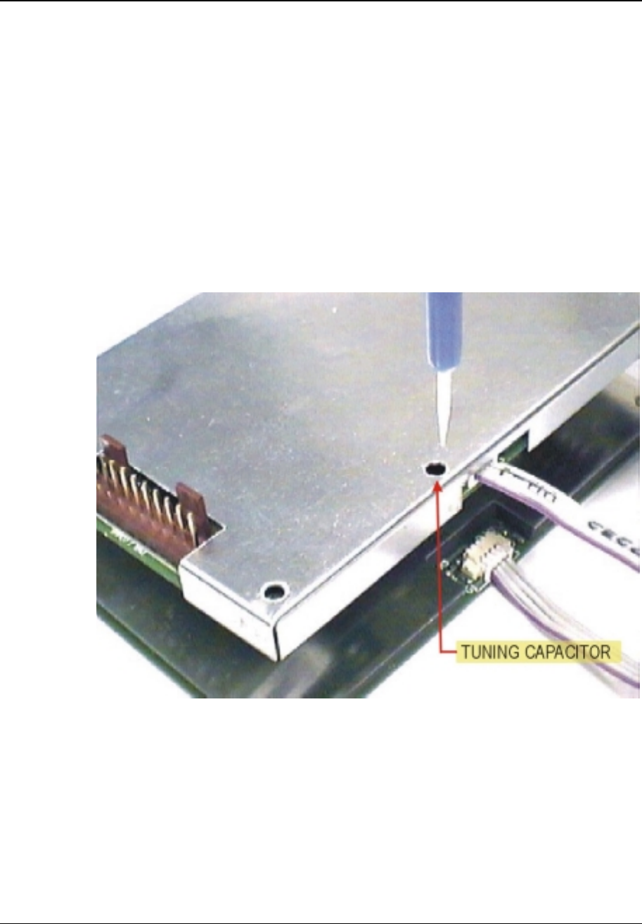
7 Antenna Tuning
The MCR200 is tuned at the factory for maximum operating range. It may be necessary to
retune the MCR200 when it is mounted into a host device to compensate for the effects of
the mounting environment (such as metallic parts or metallic paint near the antenna) and to
ensure optimum performance. For this function, use an active smart card that is initialised
for use with the particular host application.
1) With the MCR200 mounted in its operational environment place the test smart card
onto the card reading surface of the terminal. Use a non-metallic spacer with the
depth of the desired operating range. For example, if the desired operating range is
50 mm, then place a 50 mm spacer. Ensure that the host and MCR200 are powered.
2) Verify operational range by running the host internal diagnostic routines. Via the
tuning hole in the shield, adjust the tuning by rotating CV1 using a plastic tuning tool to
maximise the operating distance.
Figure 10: Location of tuning capacitor CV1