ESPRESSIF SYSTEMS ESP32WROVERB Wi-Fi & Bluetooth Module User Manual
ESPRESSIF SYSTEMS (SHANGHAI) PTE LTD Wi-Fi & Bluetooth Module
UserManual.wiki
>
ESPRESSIF SYSTEMS
>
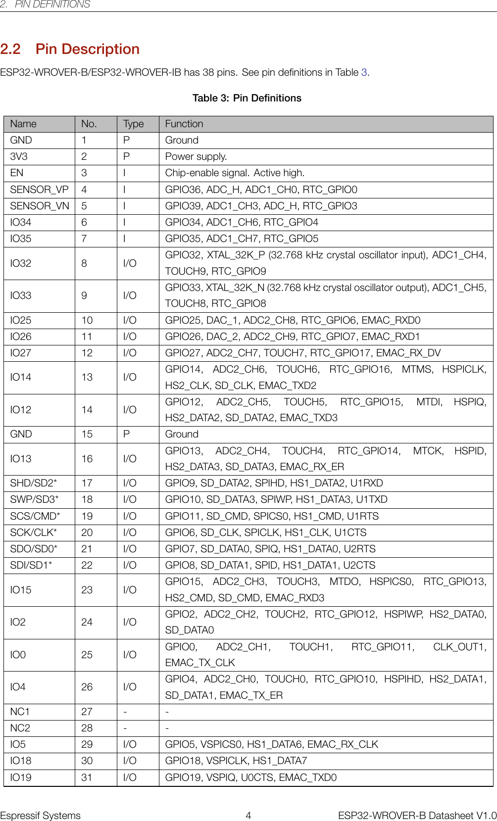
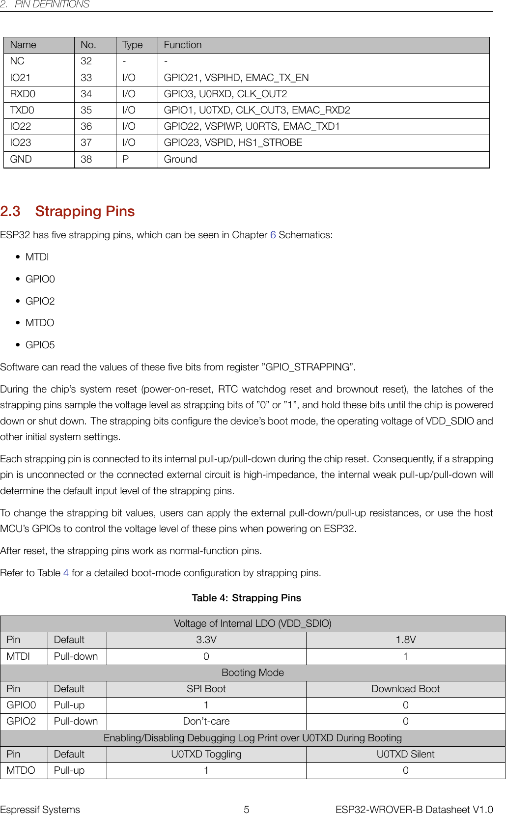
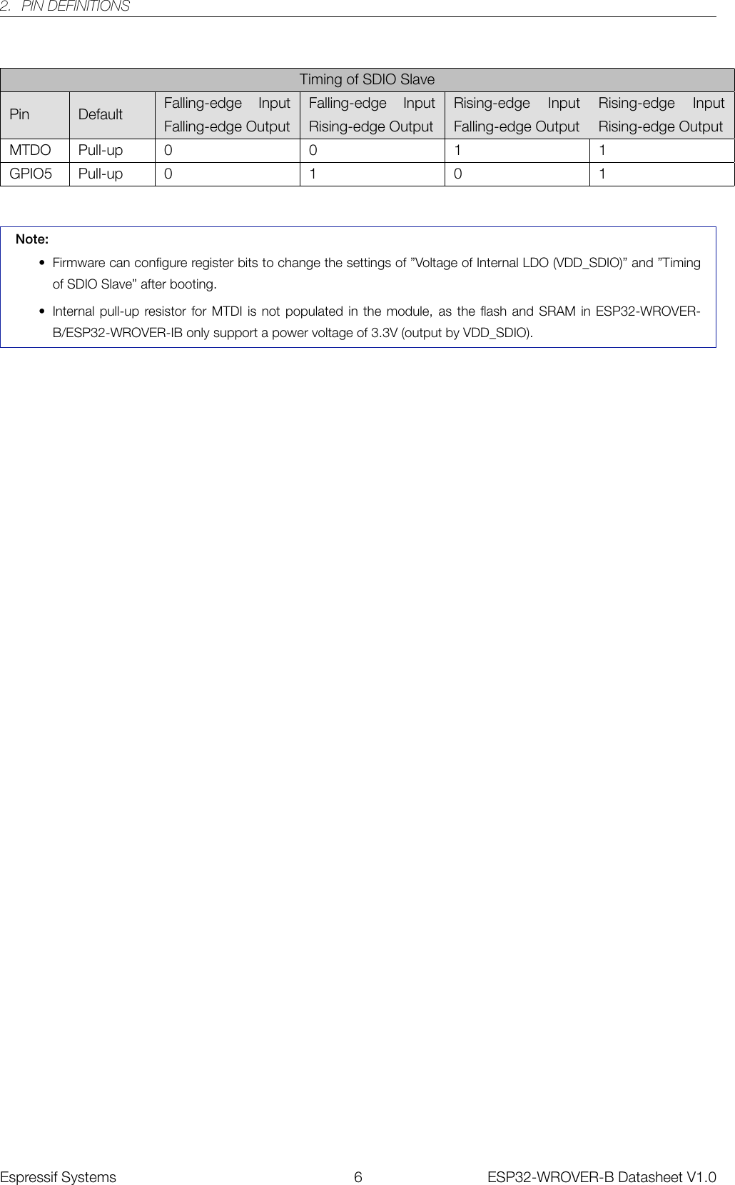
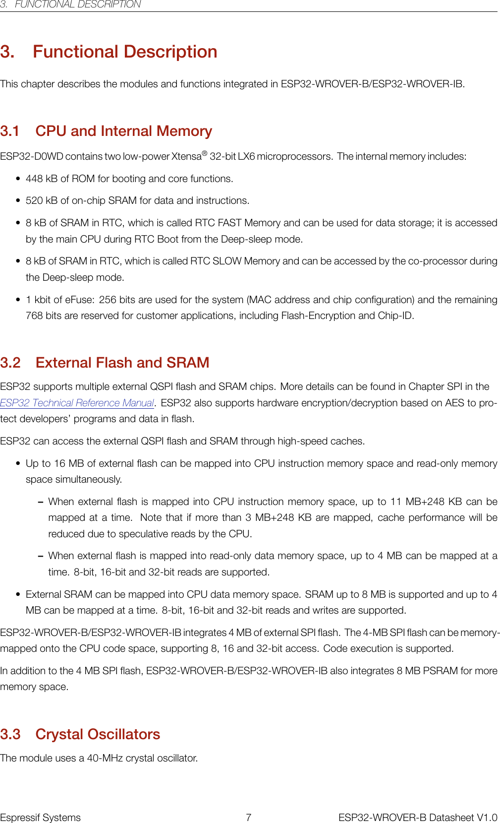
ESP32WROVERB User Manual
User Manual
Navigation menu
Upload a User Manual
Namespaces
Wiki Guide
HTML
PDF
Info
Views
User Manual
Discussion / Help
Navigation