ESPRESSIF SYSTEMS ESPWROOM02D Wi-Fi Internet of Things Module User Manual ESP WROOM 02D User Guide EN
ESPRESSIF SYSTEMS (SHANGHAI) PTE LTD Wi-Fi Internet of Things Module ESP WROOM 02D User Guide EN
User manual

!
Version 1.0
Copyright © 2017
ESP-WROOM-02D
User Guide

About This Guide
This document takes ESP-WROOM-02D as examples to introduce how to use the
ESP8266 SDK. The contents include preparations before compilation, SDK compilation
and firmware download.
Release Notes
Date
Version
Release notes
2017.11
V1.0
First release.

Table of Contents
1. ESP-WROOM-02D Overview 1 ................................................................................................
2. ESP-WROOM-02D Pin Description 2 .......................................................................................
3. Hardware Preparation for Compiling ESP-WROOM-02D 4 ....................................................
3.1. Hardware Preparation!4"................................................................................................................
3.2. Hardware Connection!4"................................................................................................................
4. Software Preparation for Compiling ESP-WROOM-02D 6 .....................................................
4.1. RTOS SDK!6".................................................................................................................................
4.2. ESP8266 Toolkit!8".........................................................................................................................
4.2.1. Compiler!8 ........................................................................................................................
4.2.2. Firmware Download Tool!10 ..............................................................................................
5. Compiling the SDK 11 ..............................................................................................................
5.1. Preparations!11".............................................................................................................................
5.1.1. Modifying SDK Files!11 .....................................................................................................
5.1.2. Downloading SDK Files!11 ................................................................................................
5.2. Compilation!13"..............................................................................................................................
5.2.1. Compile ESP8266_NONOS_SDK_v0.9.5 and Later Versions!13 .......................................
5.2.2. ESP8266_NONOS_SDK_v0.9.4 and Earlier Versions!14 ...................................................
6. Downloading the Firmware 15 .................................................................................................
6.1. Download Procedure!15"...............................................................................................................
6.2. Check Log File!17".........................................................................................................................
6.2.1. ESP8266 IOT Demo!17 ....................................................................................................
6.2.2. ESP8266 AT!18 ................................................................................................................
6.3. Configuration of RF initialization (Optional)!18"..............................................................................
6.3.1. Configuration of RF InitConfig Options!19 .........................................................................
6.3.2. Configuration of RF InitConfig Parameters!20 ....................................................................
6.3.3. Configuration Examples!22...............................................................................................

"
1. ESP-WROOM-02D Overview
1. ESP-WROOM-02D Overview
The ESP-WROOM-02D is a new ESP8266EX-based module developed by Espressif. It
differs from the ESP-WROOM-02 in that it is compatible both with 150-mil and 208-mil
flash (with 150-mil flash embedded by default). The ESP-WROOM-02D also features
optimized antenna and RF performance.
📖 Note:
For more information on ESP8266EX, please refer to ESP8266EX Datasheet.
Table 1-1. ESP-WROOM-02D Specifications
Categories
Items
Specifications
Wi-Fi
Wi-Fi protocols
802.11 b/g/n
Frequency range
2.4 GHz ~ 2.5 GHz (2400M ~ 2483.5M)
Hardware
Peripheral interface
UART/HSPI/I2C/I2S/IR Remote Control
GPIO/PWM
Operating voltage
2.7V ~ 3.6V
Operating current
Average: 80 mA
Minimum current delivered by
power supply
500 mA
Operating temperature range
-40°C ~ 85°C
Storage temperature
-40°C ~ 85°C
Package size
(18±0.2) mm x (20±0.2) mm x (3.2±0.15) mm
External interface
-
Software
Wi-Fi mode
Station/SoftAP/SoftAP+Station
Security
WPA/WPA2
Encryption
WEP/TKIP/AES
Firmware upgrade
UART Download/OTA (via network)/Download and write
firmware via host
Software development
Supports Cloud Server Development/SDK for custom
firmware development
Network protocols
IPv4, TCP/UDP/HTTP/FTP
User configuration
AT Instruction Set, Cloud Server, Android/iOS app
Espressif
"/"1 23
2017.11
"
2. ESP-WROOM-02D Pin Description
2. ESP-WROOM-02D Pin
Description
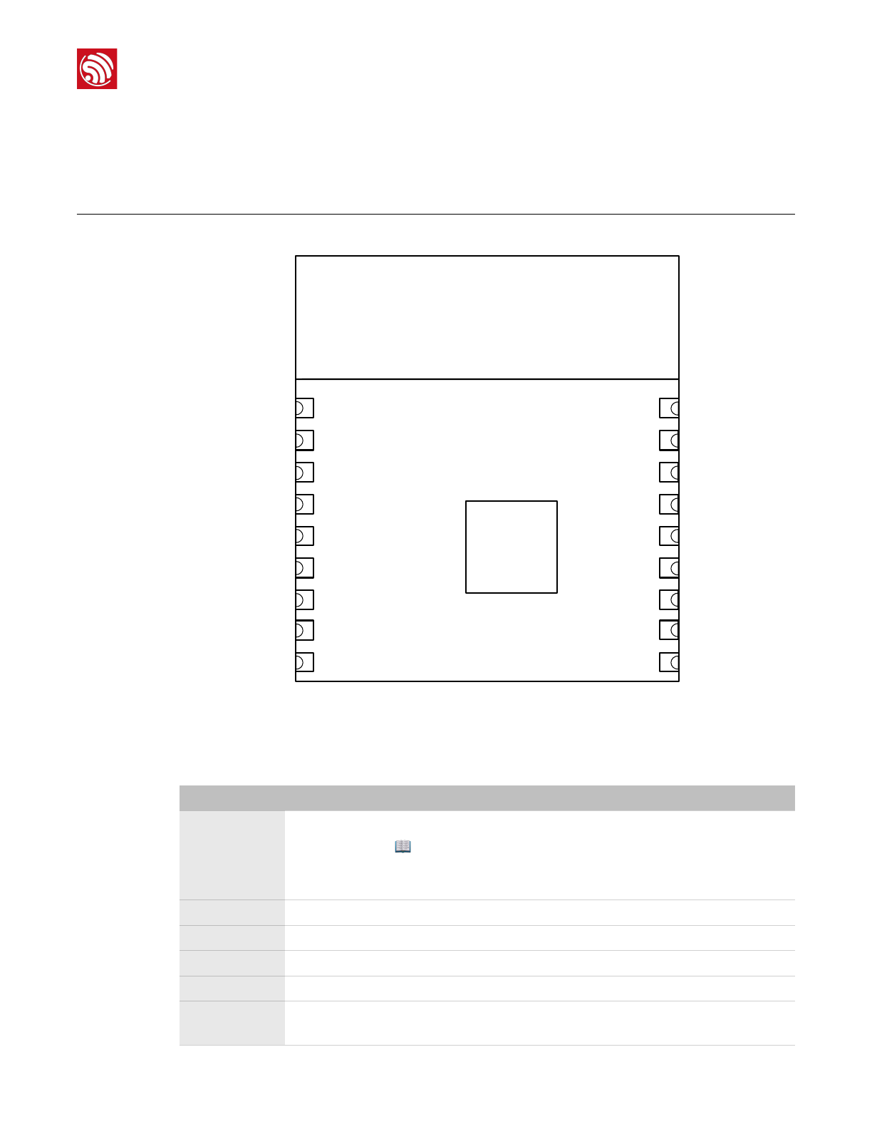
Figure 2-1 shows the pin distribution of the ESP-WROOM-02D.
"
Figure 2-1. ESP-WROOM-02D Pin Layout
ESP-WROOM-02D has 18 pins. Please see the pin definitions in Table 2-1.
19GND
PCB ANTENNA
GND
IO16
TOUT
RST
IO5
GND
TXD
RXD
IO4
3V3
EN
IO14
IO12
IO13
IO15
IO2
IO0
GND
9
8
7
6
5
4
3
2
1
10
11
12
13
14
15
16
17
18
Table 2-1. ESP-WROOM-02D Pin Definitions
No.
Pin Name
Functional Description
1
3V3
3.3V power supply (VDD)
📖 Note:
It is recommended the maximum output current a power supply
provides be of 500 mA or above.
2
EN
Chip enable pin. Active high.
3
IO14
GPIO14; HSPI_CLK
4
IO12
GPIO12; HSPI_MISO
5
IO13
GPIO13; HSPI_MOSI; UART0_CTS
6
IO15
GPIO15; MTDO; HSPICS; UART0_RTS
Pull down.
Espressif
"/"2 23
2017.11

"
2. ESP-WROOM-02D Pin Description
7
IO2
GPIO2; UART1_TXD
Floating (internal pull-up) or pull up.
8
IO0
GPIO0
•UART download: pull down.
•Flash boot: floating or pull up.
9
GND
GND
10
IO4
GPIO4
11
RXD
UART0_RXD, receive end in UART download;
GPIO3
12
TXD
UART0_TXD, transmit end in UART download, floating or pull up;
GPIO1
13
GND
GND
14
IO5
GPIO5
15
RST
Reset
16
TOUT
It can be used to test the power-supply voltage of VDD3P3 (Pin3 and
Pin4) and the input power voltage of TOUT (Pin6). These two functions
cannot be used simultaneously.
17
IO16
GPIO16; used for Deep-sleep wake-up when connected to RST pin.
18
GND
GND
No.
Pin Name
Functional Description
Espressif
"/"3 23
2017.11
"
3. Hardware Preparation for Compiling ESP-WROOM-02D
3. Hardware Preparation for
Compiling ESP-WROOM-02D
3.1. Hardware Preparation
•ESP-WROOM-02D module
•USB-to-TTL converter (FT232R recommended)
•PC for programming: Windows XP or Windows 7 OS is recommended, with enough
RAM to run a Linux virtual machine.
•Micro-USB cable
3.2. Hardware Connection
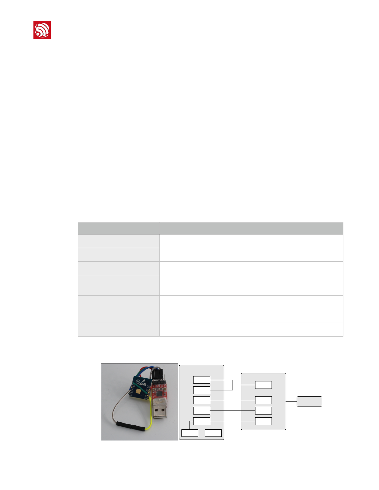
1. Lead out the pins of the ESP-WROOM-02D, as shown in Table 2-2.
2. Connect ESP-WROOM-02D to the USB-to-TTL converter, using Dupont lines, as
shown in Figure 2-1.
! !
Table 2-2. ESP-WROOM-02D Pins
Pin
Pin status
EN
Pull up
3V3
3.3V power supply (VDD)
IO15
Pull down
IO0
UART download: pull down;
Flash boot: floating/pull up
GND
GND
RXD
Receive-end in UART download
TXD
Transmit-end in UART download; floating/pull up
EN
3V3
ESP-WROOM-02
3V3
TXD
RXDTXD
RXD
GNDGND
IO15 IO0
USB-to-TTL converter
PC
Espressif
"/"4 23
2017.11

"
3. Hardware Preparation for Compiling ESP-WROOM-02D
Figure 2-1. ESP-WROOM-02D Download Mode
3. Connect the USB-to-TTL converter to the PC.
4. Download firmware to flash with the ESP8266 DOWNLOAD TOOL.
5. After downloading, switch ESP-WROOM-02U to working mode."
Set IO0 as floating or pull-up.
6. Power on ESP-LAUNCHER again and the chip will read and run programs from the
flash.
——🔚
📖 Note:
On how to download firmware, please refer to Chapter 4, "Flash Maps" and Chapter 6, "Downloading the
Firmware".
📖 Notes:
•IO0 is an internal pull-up pin.
•For more information on ESP-WROOM-02U hardware, please refer to ESP8266 System
Description and ESP-WROOM-02 Datasheet.
Espressif
"/"5 23
2017.11
"
4. Software Preparation for Compiling ESP-WROOM-02D
4. Software Preparation for
Compiling ESP-WROOM-02D
Users can download the non-OS SDK (including application examples) from:"
http://www.espressif.com/en/support/download/sdks-demos?
keys=&field_type_tid%5B%5D=14.
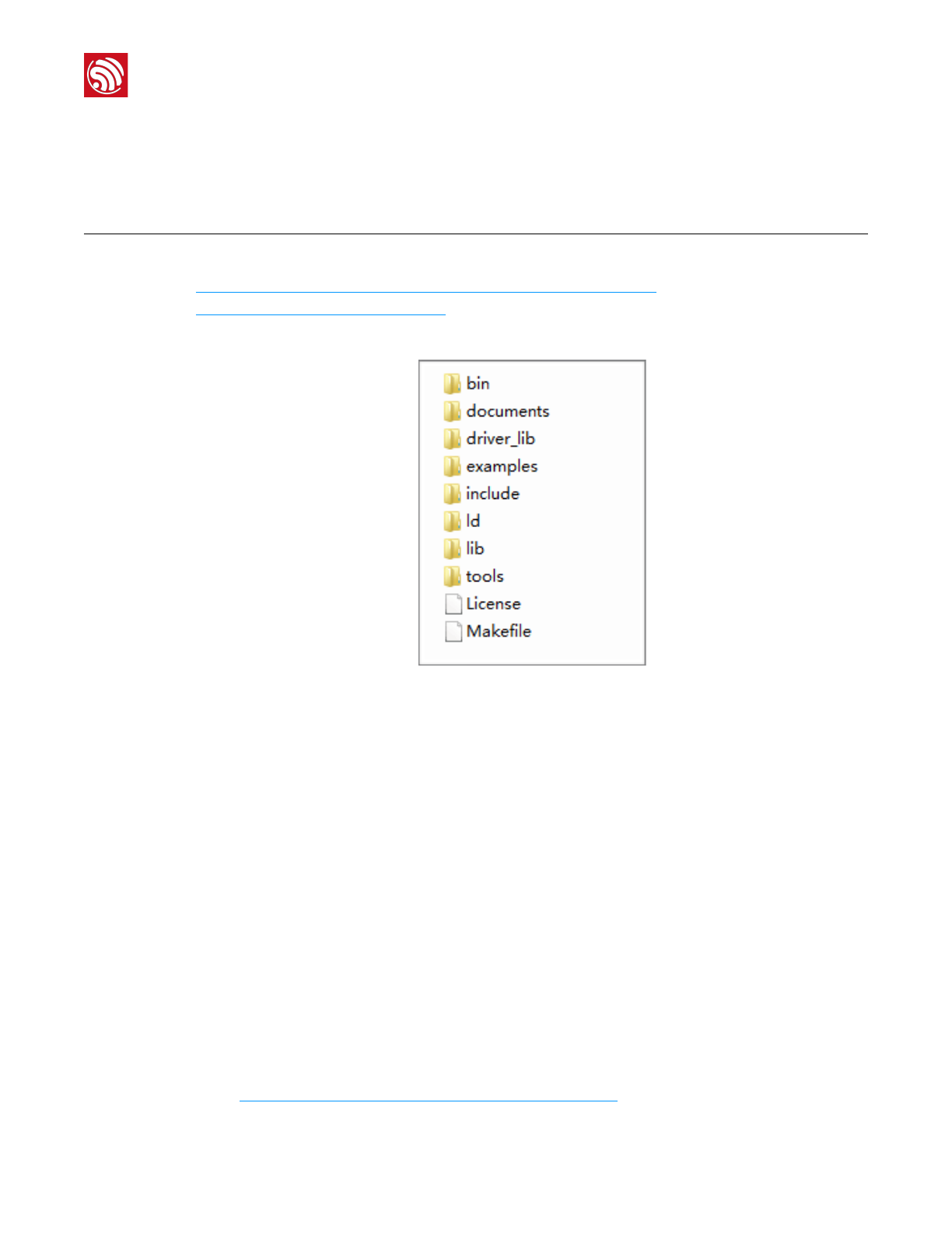
Figure 3-1 shows the directory structure of the non-OS SDK.
"
Figure 3-1. Non-OS SDK Directory Structure
•bin: compiled binaries to be downloaded directly into the flash.
•documents: SDK-related documents or links.
•driver_lib: library files that drive peripherals, such as UART, I2C and GPIO.
•examples: sample codes for secondary development, for example, IoT Demo.
•include: header files pre-installed in SDK. The files contain relevant API functions and
other macro definitions. Users do not need to modify them.
•ld: linker scripts. We suggest users not modifying them without any specific reasons.
•lib: library files provided in SDK.
•tools: tools needed for compiling binaries. Users do not need to modify them.
4.1. RTOS SDK
Users can download RTOS SDK and its application examples (ESP8266_IOT_PLATFORM)
from:
•RTOS SDK"
https://github.com/espressif/ESP8266_RTOS_SDK
Espressif
"/"6 23
2017.11
"
4. Software Preparation for Compiling ESP-WROOM-02D
•ESP8266_IOT_PLATFORM"
https://github.com/espressif/ESP8266_IOT_PLATFORM
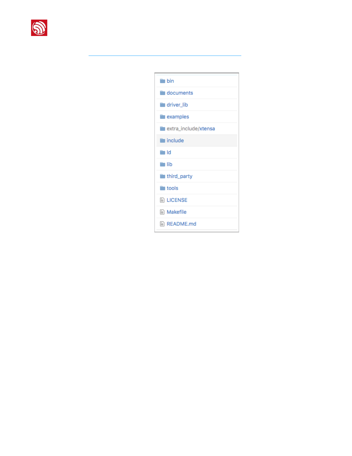
Table 3-2 shows the directory structure of the RTOS SDK.
"
Figure 3-2. RTOS SDK Directory Structure
•bin: boot and initialization firmware.
•documents: ESP8266_RTOS_SDK files.
•driver_lib: sample codes of drivers.
•examples: sample codes for Espressif’s application programs.
-openssl_demo: sample codes of the openssl API function.
-project_template: sample codes of project templates.
-smart_config: sample codes of SmartConfig.
-spiffs_test: sample codes of the spiffs file system function.
-websocket_demo: sample codes of web socket.
•include: header files of ESP8266_RTOS_SDK, including software interfaces and
macro functions for users to use.
•ld: link files used when compiling; users do not need to modify them.
•lib: library file of ESP8266_RTOS_SDK.
•third_party: third-party library of Espressif’s open-source codes, currently including
free RTOS, JSON, lwIP, mbedTLS, noPoll, OpenSSL, spiffs, and SSL.
•tools: tools needed for compiling binaries; users do not need to modify them.
Espressif
"/"7 23
2017.11
"
4. Software Preparation for Compiling ESP-WROOM-02D
4.2. ESP8266 Toolkit
4.2.1. Compiler
Please download VirtualBox from: https://www.virtualbox.org/wiki/Downloads.
Please download the compiler ESP8266_lubuntu_20141021.ova from:
http://downloads.espressif.com/FB/ESP8266_GCC.zip
📖 Note:
Please choose the right version of VirtualBox according to the host machine's OS.
Steps
Results
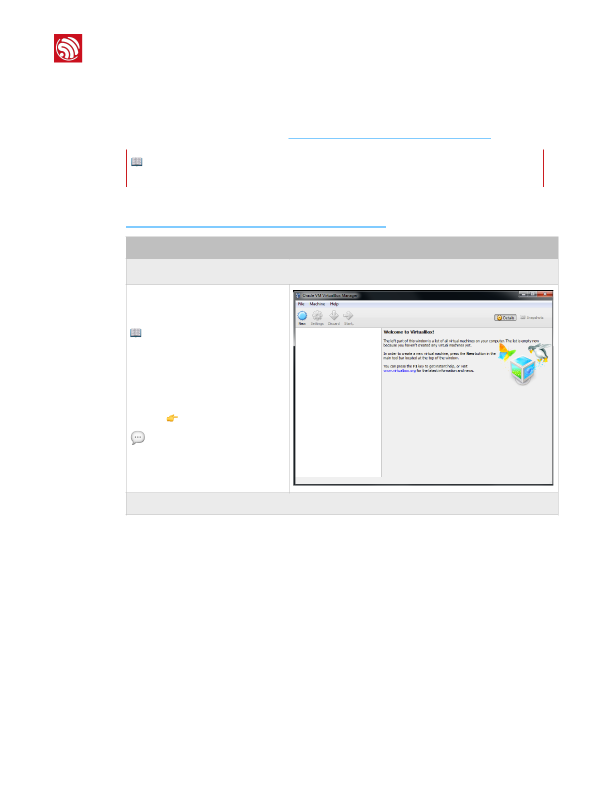
1. Start Windows OS and install the virtual machine.
•Double-click
VirtualBox-5.0.16-105871-Win.exe
and install VirtualBox.
📖 Note:
VirtualBox has different versions. We are
using Windows V.5.0.16 as an
example.
•Double-click Oracle VM
VirtualBox.exe to run the program,
and the system will show the main
menu 👉.
💬Tip:
The ESP8266 virtual machine takes up
much space (memory). Please reserve
enough space for it.
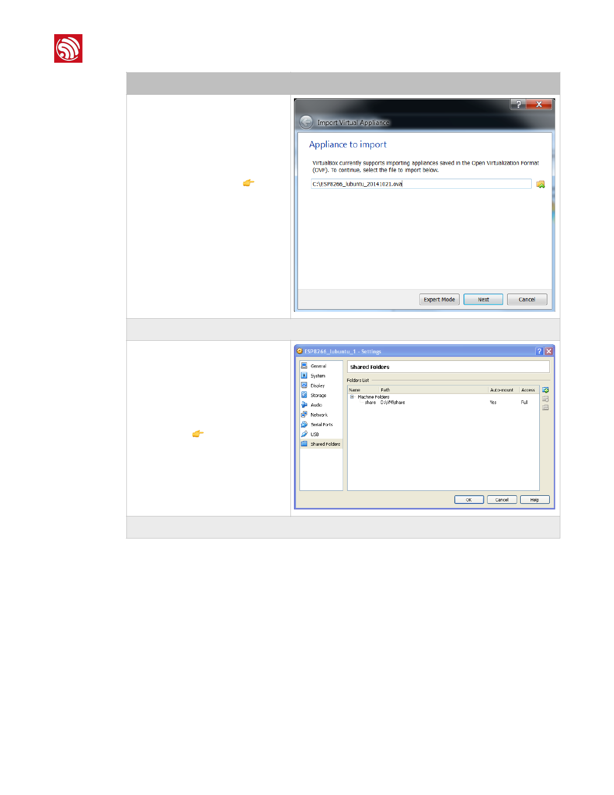
2. Import the image file.
"
Espressif
"/"8 23
2017.11
"
4. Software Preparation for Compiling ESP-WROOM-02D
•Select File > Import Appliance, and
a dialog box will show up 👉.
•Select the image file to import, for
example, C:
\ESP8266_lubuntu_20141021.ova,
and click Next.
•Click Import to confirm the settings.
3. Create a shared folder.
•Create a new folder named D:
\VM\share.
•Select Machine > Settings >
Shared Folders…, and a dialog box
will show up 👉.
•Select the shared folder in Machine
Folders, for example, D:\VM\share.
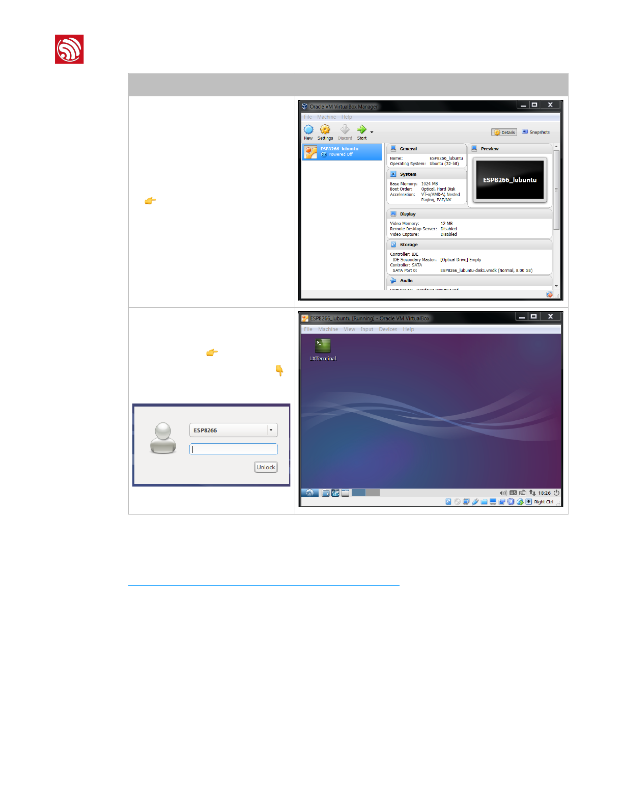
4. Run the virtual machine.
Steps
Results
Espressif
"/"9 23
2017.11
"
4. Software Preparation for Compiling ESP-WROOM-02D
4.2.2. Firmware Download Tool
Please download the ESP8266 DOWNLOAD TOOL from:
http://www.espressif.com/support/download/other-tools.
•After importing, a virtual machine
named ESP8266_lubuntu shows up
👉.
•Double-click ESP8266_lubuntu or
Start to run the virtual machine.
Steps
Results
•The system shows the ESP8266
virtual machine 👉.
•If a dialog box like the one below👇
shows up, please enter the
password: espressif.
"
Espressif
"/"10 23
2017.11
"
5. Compiling the SDK
5. Compiling the SDK
5.1. Preparations
1. Modifying SDK Files
1. Start Windows OS.
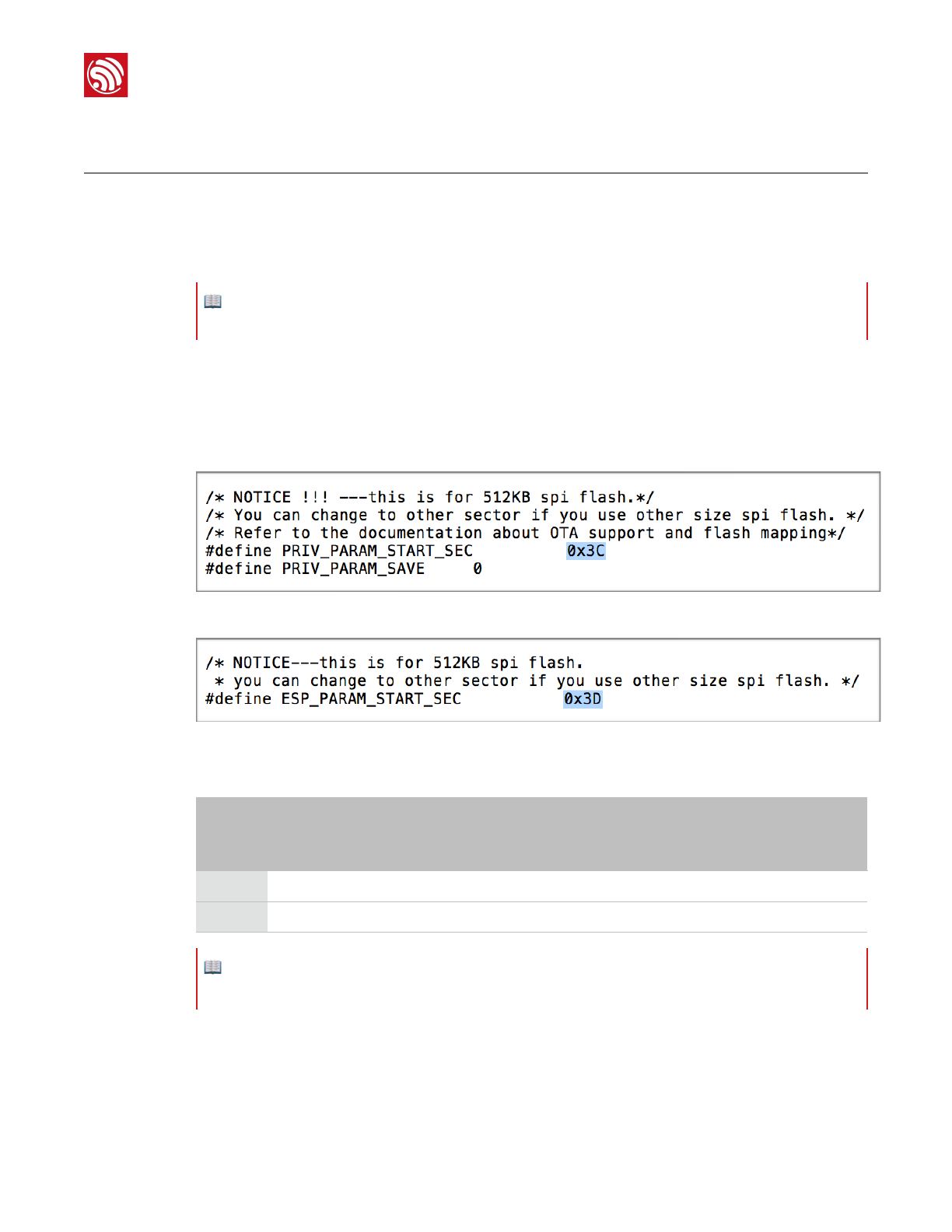
2. Modify files in ESP8266_NONOS_SDK/examples/IoT_Demo/include according to the
flash map.
•Modify #definePRIV_PARAM_START_SEC in user_light.h and user_plug.h.
"
•Modify #defineESP_PARAM_START_SEC in user_esp_platform.h.
"
Table 5-1 lists the modified values.
2. Downloading SDK Files
1. Start Linux OS.
2. Run LXTerminal on the desktop of the virtual machine.
📖 Note:
Users need to modify the SDK files if using the OTA firmware.
Table 5-1. Modify the Field Values in the "include" File (unit: kB)
Default
value
(512)
Modified values
512
1024
2048
(512+512)
2048
(1024+1024)
4096
(512+512)
4096
(1024+1024)
8192
(1024+1024)
16384
(1024+1024)
0x3C
-
0x7C
0x7C
0xFC
0x7C
0xFC
0xFC
0xFC
0x3D
-
0x7D
0x7D
0xFD
0x7D
0xFD
0xFD
0xFD
📖 Note:
Users need not modify the SDK files if using a 512-KB flash.
Espressif
"/"11 23
2017.11
"
5. Compiling the SDK
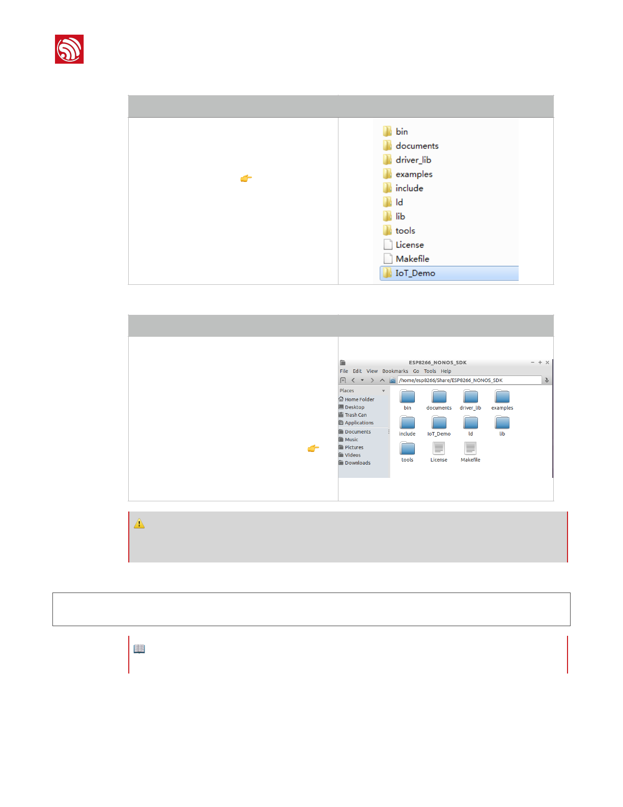
3. Copy the files to be compiled to the shared folder.
4. Download shared directory.
5. Set the variable PATH to point to SDK and binaries.
exportSDK_PATH=~/Share/ESP8266_RTOS_SDK
exportBIN_PATH=~/Share/ESP8266_RTOS_SDK/bin
Steps
Results
•Copy ESP8266_NONOS_SDK folder to the
shared directory, for example, C:\VM\share.
•Copy IoT_Demo folder to C:
\VM\share\ESP8266_NONOS_SDK, as shown
in the figure on the right 👉.
Steps
Results
•Execute ./mount.sh.
•Input the password: espressif."
Downloading shared files is completed.
•Open the shared directory
ESP8266_NONOS_SDK in the virtual machine
and confirm whether the download has been
successful.
- If successful, the directory contains such
files as those in the figure on the right 👉.
- If not, the directory will be empty, and users
will need to go over this step again.
⚠ Notice:
If users use the RTOS SDK, please continue with the following steps; if use the non-OS SDK, please skip
Step 5.
📖 Note:
Users can add it to .bashrc file, otherwise Step 5 needs to be repeated each time the compiler is restarted.
Espressif
"/"12 23
2017.11
"
5. Compiling the SDK
5.2. Compilation
5.2.1. Compile ESP8266_NONOS_SDK_v0.9.5 and Later Versions
2. Switch to the /Share/ESP8266_NONOS_SDK/IoT_Demo directory in the terminal.
cd/home/esp8266/Share/ESP8266_NONOS_SDK/IoT_Demo
./gen_misc.sh
The system shows the following information:
gen_misc.shversion20150511
Pleasefollowbelowsteps(1-5)togeneratespecificbin(s):
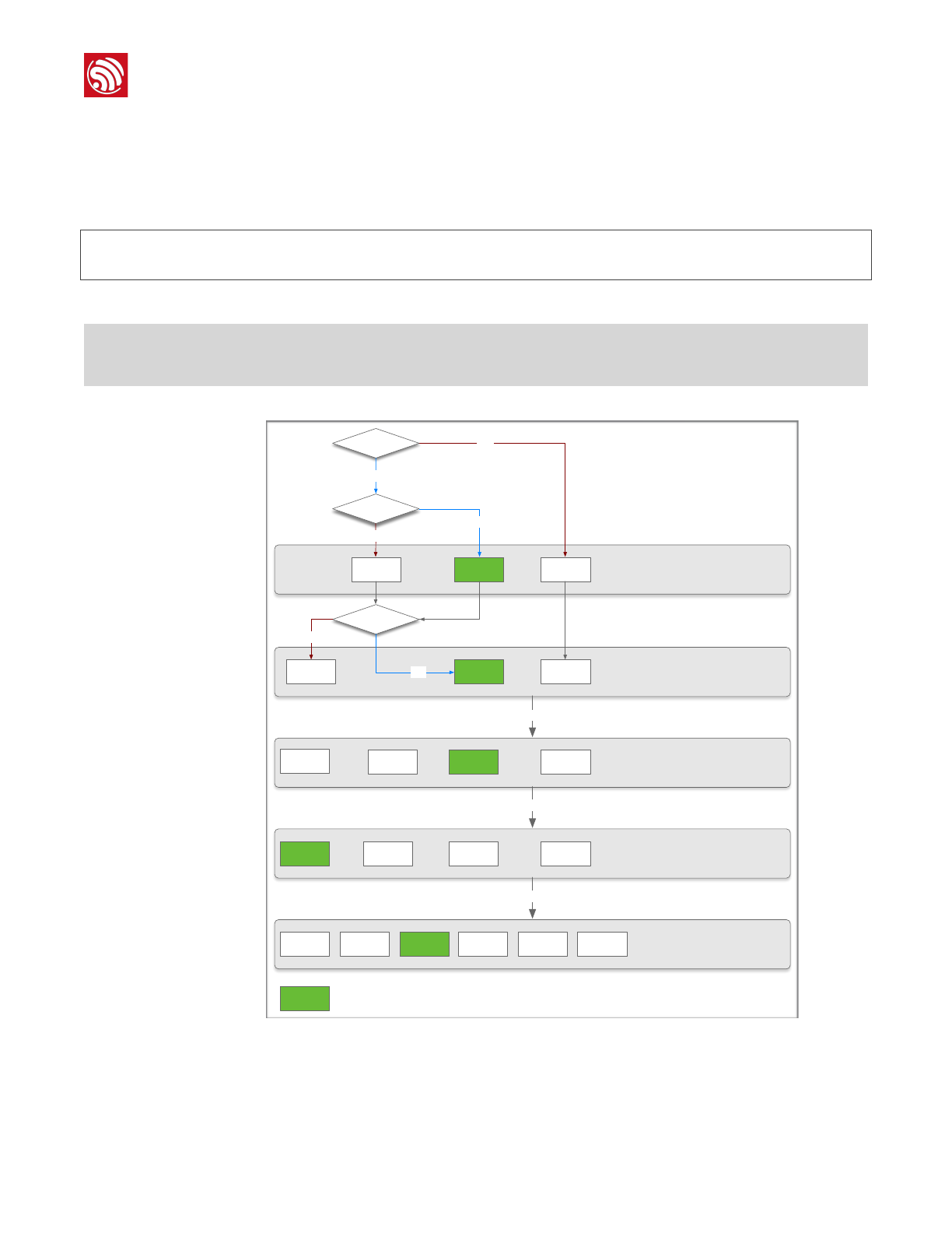
3. Select the required options as shown in Figure 5-1.
"
Figure 5-1. Compile SDK
012
0
STEP 1: choose boot version
(0=boot_v1.1, 1=boot_v1.2+, 2=none)
enter(0/1/2, default 2)
STEP 2: choose bin generate
(0=eagle.flash.bin+eagle.irom0text.bin
, 1=user1.bin, 2=user2.bin)
enter (0/1/2, default 0)
FOTA? N
New
version?
Y
N
Y
First-time
usage?
2
N
1Y
01 2 3
STEP 3: choose spi speed
(0=20MHz, 1=26.7MHz, 2=40MHz, 3=80MHz)
enter (0/1/2/3, default 2)
0 1 2 3
STEP 4: choose spi mode
(0=QIO, 1=QOUT, 2=DIO, 3=DOUT)
enter (0/1/2/3, default 0)
0 2 3
STEP 5: choose spi size and map
0= 512KB( 256KB+ 256KB)
enter (0/2/3/4/5/6, default 0)
Choose as required
Choose as required
Choose as required
4 5 6
Example Option
Espressif
"/"13 23
2017.11

"
5. Compiling the SDK
4. After compilation, the generated binaries and the addresses in flash are shown as
follows:
Generateuser1.2048.new.3.binsuccessfullyinfolderbin/upgrade.
boot.bin------------>0x00000
user1.2048.new.3.bin--->0xSupportboot_v1.2and+
01000
!!!
−−🔚
5.2.2. ESP8266_NONOS_SDK_v0.9.4 and Earlier Versions
For ESP8266_NONOS_SDK_v0.9.4 and previous versions, the compilation process is as
follows:
1. Execute ./gen_misc_plus.sh 1 to generate user1.bin under the"
/ESP8266_NONOS_SDK/bin/upgrade path.
2. Execute makeclean to clear previous compilation data.
3. Execute ./gen_misc_plus.sh2 to generate user2.bin under the"
/ESP8266_NONOS_SDK/bin/upgrade path.
📖 Notes:
•The sample options are marked in green. Users can select the right options as needed.
•For OTA and non-OTA firmware, please refer to Section 1.4, "ESP8266 FW".
•Only sdk_v1.1.0 + boot 1.4 + flash download tool_v1.2 and higher versions support options 5 and 6 in
Step 5.
•After compiling user1.bin, execute makeclean first to clear the temporary files generated by the last
compilation, and then compile user2.bin.
•For the flash map in Step 5, please refer to Chapter 4, "Flash Maps".
📖 Note:
Users can open the /home/esp8266/Share/ESP8266_NONOS_SDK/bin directory and check the compiled
binaries.
📖 Note:
ESP8266_NONOS_SDK_v0.7 and earlier are non-OTA firmware.
Espressif
"/"14 23
2017.11
"
6. Downloading the Firmware
6. Downloading the Firmware
6.1. Download Procedure
1. Start Windows OS.
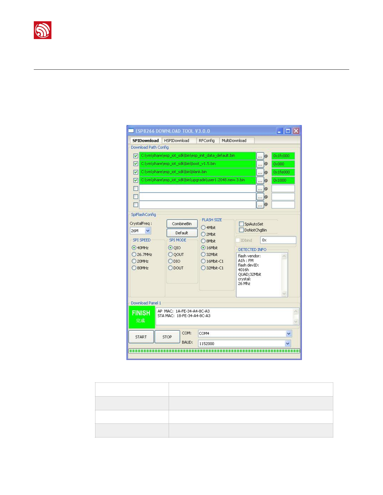
2. Double-click ESP_DOWNLOAD_TOOL.exe to open Flash tool.
Figure 6-1. ESP8266 DOWNLOAD TOOL—SPIDownload
SPIDownload
For SPI Flash download.
HSPIDownload
For HSPI Flash download.
RFConfig
RF initialization Configuration.
MutiDownload
For multi-mother boards download.
Espressif
"/"15 23
2017.11
"
6. Downloading the Firmware
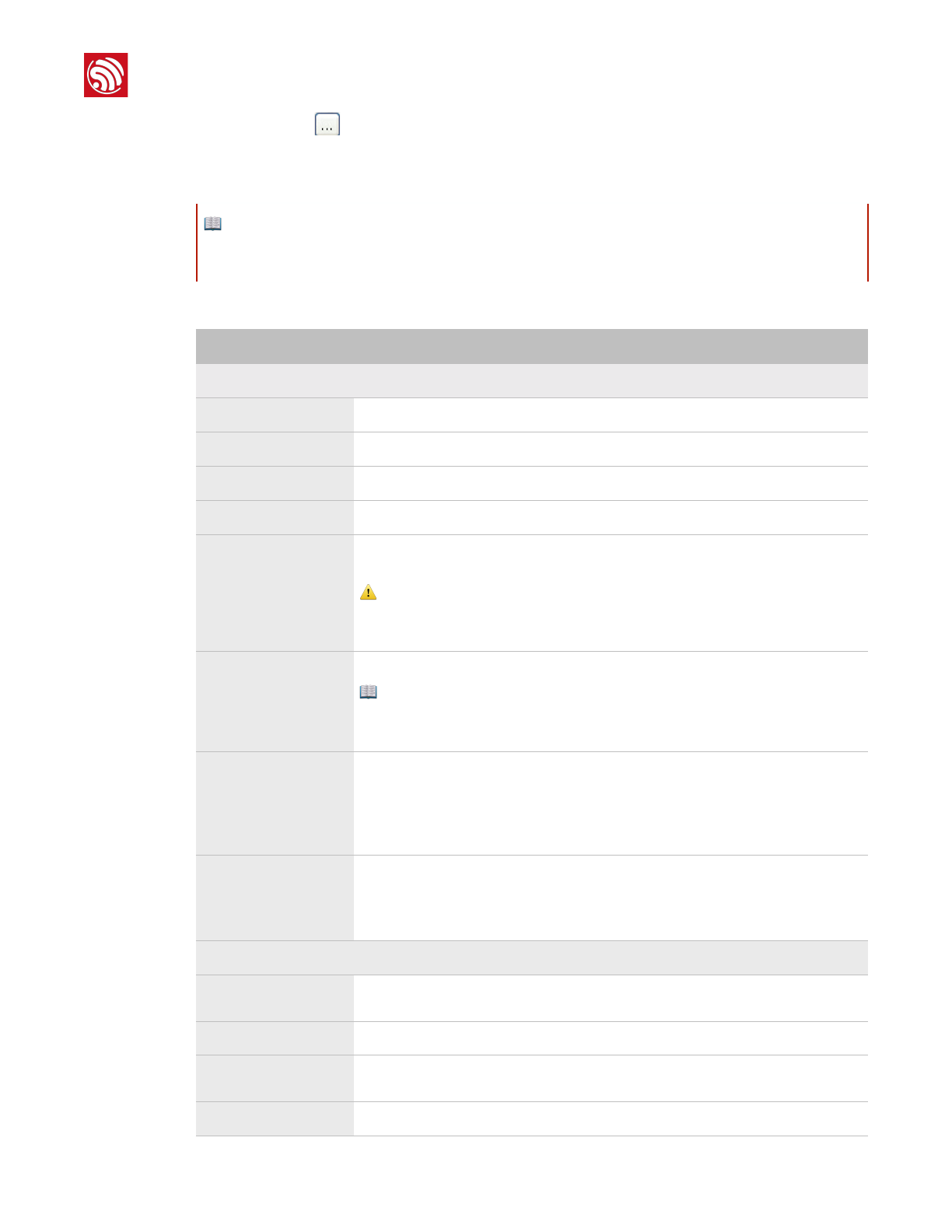
3. Double-click " in Download Path Config panel to select the binaries to be
downloaded. Set the corresponding download addresses in ADDR.
4. Configure SPIDownload.
📖 Note:
The binaries to be downloaded and the corresponding addresses vary with different SPI Flash sizes and
actual demands. For details, please refer to Chapter 4, "Flash Maps".
Table 6-1. SPIDownload Configuration
Items
Description
SPI FLASH CONFIG
CrystalFreq
Select the crystal frequency according to the crystal oscillator used.
CombineBin
Combine the selected binaries into target.bin with the address 0x0000.
Default
Set the SPI Flash to the default value.
SPI SPEED
Select SPI read/write speed with the maximum value of 80 MHz.
SPI MODE
Select SPI mode according to the SPI Flash used. If the flash is Dual SPI, select
DIO or DOUT. If the flash is Quad SPI, select DIO or DOUT.
⚠ Notice:
If ISSI Flash is used, please refer to Appendix, "Configure ISSI & MXIC Flash QIO
Mode".
FLASH SIZE
Select the flash size according to the flash type.
📖 Note:
16Mbit-C1 refers to 1024+1024 flash map and 32Mbit-C1 1024+1024 flash map
as well.
SpiAutoSet
We recommend not checking SpiAutoSet, but configuring the flash manually as
needed.
If users select SpiAutoSet, the binaries will be downloaded according to the
default flash map. The flash map of 16 Mbit and 32 Mbit will be 512 KByte + 512
KByte.
DoNotChgBin
•If users select DoNotChgBin, the flash working frequency, mode, and flash
map will be based on the configuration when compiling.
•If users do not select DoNotChgBin, the flash working frequency, mode, and
flash map will be defined by the final configuration of the compiler.
Download Panel
START
Click START to start download. When the download completes, FINISH will
appear in the green area on the left.
STOP
Click STOP to stop download.
MAC Address
If download is successful, the system will show the MAC addresses of ESP8266
STA and ESP8266 AP.
COM PORT
Select the actual COM port of ESP8266.
Espressif
"/"16 23
2017.11

"
6. Downloading the Firmware
5. After downloading, turn GPIO0 Control on ESP-LAUNCHER to the outer side and power
the board on to enable the working mode.
6.2. Check Log File
After downloading firmware, users can check the log printed in the terminal by using the
serial port debug tool.
Users need to configure the settings of the serial port debug tool, as follows:
6.2.1. ESP8266 IOT Demo
If users download ESP8266 IOT Demo firmware, the system in working mode will show the
initialization information including the SDK version, etc. “Finish” means the firmware works
properly.
SDKversion:X.X.X(e67da894)
IOTVERSION=v1.0.5t45772(a)
resetreason:0
PWMversion:00000003
mode:sta(18:fe:34:a4:8c:a3)+softAP(1a:fe:34:a4:8c:a3)
BAUDRATE
Select the baud rate of downloading. The default value is 115200.
Items
Description
SPI FLASH CONFIG
Table 6-2. Serial Port Debug Tool Configuration
Items
Configuration Description
Protocol
Serial port.
Port number
Set the port number according to the connected device.
Baud rate
The baud rate at which the device is running, related to the crystal oscillator.
•69120 (24 M crystal oscillator)
•74880 (26 M crystal oscillator)
•115200 (40 M crystal oscillator)
The ESP8266 AT example supports the baud rate of 115200 by default.
Users cannot modify it.
The ESP8266 IOT Demo example supports the baud rate of 74880. Users
can modify it.
Data bit
8
Calibration
None.
Flow control
None.
Espressif
"/"17 23
2017.11

"
6. Downloading the Firmware
addif0
addif1
dhcpserverstart:(ip:192.168.4.1,mask:255.255.255.0,gw:192.168.4.1)
bcn100
finish
6.2.2. ESP8266 AT
If users download the ESP8266 AT firmware, or the default firmware in ESP-LAUNCHER or
ESP-WROOM-02U, the system in working mode will display “Ready” at the end. Input
command “AT” in the terminal and the system will return “OK”, which means that the
firmware works properly.
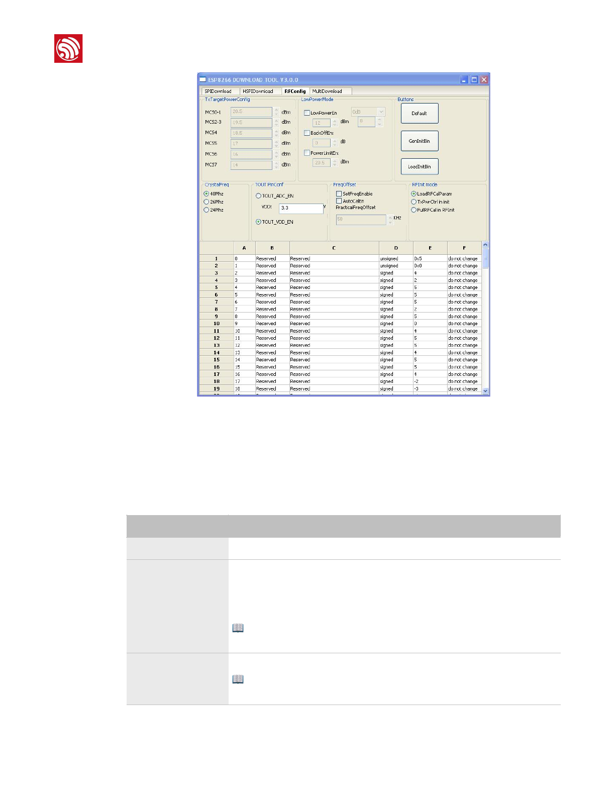
6.3. Configuration of RF initialization (Optional)
Before downloading binaries to flash, users can modify the RF initialization settings in the
RF InitConfig tab. The newly-generated esp_init_data_setting.bin can be downloaded to
the flash instead of esp_init_data_default.bin. Users can configure both the options and
the parameters of the RF settings.
📖 Notes:
•The baud rate in AT firmware is configured as 115200 manually, however, the default baud rate of
ESP8266 is 74880, due to this discrepancy, the system initialization information will be displayed as
mojibake. It is a normal phenomenon as long as the system shows “Ready” at the end.
•For more information on AT commands, please refer to ESP8266 AT Instruction Set.
Espressif
"/"18 23
2017.11
"
6. Downloading the Firmware
!
Figure 6-2. ESP8266 DOWNLOAD TOOL - RF InitConfig
6.3.1. Configuration of RF InitConfig Options
RF InitConfig options are listed in the upper part of Figure 6-2. Please refer to Table 6-3 for
a description of this configuration.
Table 6-3. Configuration of RF InitConfig Options
Items
Description
TxTargetPowerConfig
Users need not configure this. It varies with the options in LowPowerMode.
LowPowerMode
Configure the low power mode as required.
•LowPowerEn: enable low power mode, set a power value for all data rates.
•PowerLimtEn: set a limit for output power.
•BackOffEn: set backoff value for each data rate.
📖 Note:
Users cannot configure LowPowerEn and PowerLimtEn at the same time.
CrystalFreq
Select the crystal oscillator frequency according to the crystal oscillator used.
📖 Note:
If a different option is selected when downloading, it will override this configuration.
Espressif
"/"19 23
2017.11
"
6. Downloading the Firmware
6.3.2. Configuration of RF InitConfig Parameters
RF InitConfig parameters are listed in the lower part of Figure 6-2. The description of
parameters’ configuration is shown in Table 6-4.
TOUT PinConf
Configure the TOUT pin according to the actual TOUT pin status. We recommend
the default value.
•TOUT_ADC_EN: When the TOUT pin connects to an external circuit,
measure the external voltage (0V - 1V) through the internal ADC.
•TOUT_VDD_EN: When TOUT pin is left floating, measure VDD33 voltage
through uint16 system_get_vdd33(void).
⚠ Notice:
•Users cannot configure TOUT_ADC_EN and TOUT_VDD_EN at the same
time.
•When users use TOUT_ADC_EN, they need to input the actual voltage on
VDD3P3 pin 3 and pin 4.
FreqOffset
•SetFreqEnable: Set the frequency offset manually.
-PracticalFreqOffset: the option is valid when selecting SetFreqEnable.
•AutoCalEn: Set the frequency offset automatically.
RFInt mode
Users can select the RF initialization mode:
•LoadRFCalParam: During the RF initialization, RF data are loaded directly
from the flash without any calibration. It takes about 2 ms and the least initial
current.
•TxPwrCtrl in init: During the RF initialization, only Tx Power calibration will
be performed, and other data are loaded from flash. It takes about 20 ms
and small initial current.
•FullRFCal in RFInit: All calibrations are performed during the RF
initialization. It takes 200 ms and large initial current.
Items
Description
Table 6-4. Configuration of RF InitConfig Parameters
Items
Description
A
The byte in esp_init_data_setting.bin (0 ~ 127 byte). For example, A = 0
represents Byte 0 in esp_init_data_setting.bin.
B
The item name. Users cannot modify it if marked as Reserved.
C
The item name. Users cannot modify it if marked as Reserved.
D
Data types of configuration items, including unsigned and signed data types.
E
The hexadecimal value of a configuration item.
⚠ Notice:
Please do not modify the parameters marked as Reserved.
Espressif
"/"20 23
2017.11
"
6. Downloading the Firmware
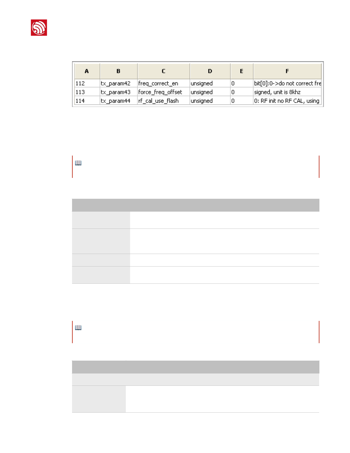
The following section introduces how to modify the 112 ~ 114 byte parameters. Figure 6-3 shows
the initial configuration.
!
Figure 6-3. 112 ~ 114 Byte Parameters
Modify the RF Initialization Parameters
Byte 114 is used to control THE RF initialization when ESP8266 is powered on. Table 6-5 provides
the parameter configuration.
Correct Frequency Offset
Byte 112 and byte 113 relate to the frequency offset correction. Table 6-6 provides the parameter
configuration.
📖 Note:
Supported by ESP8266_NONOS_SDK_V1.5.3 and ESP8266_RTOS_SDK_V1.3.0 and higher.
Table 6-5. Modify RF Initialization Parameters
Option
Description
byte 114 = 0
Only a VDD33 calibration is performed during the RF initialization. It takes about 2
ms and the least initial current.
byte 114 = 1
The default value is 1.
VDD33 and TX power calibrations are performed during the RF initialization. It takes
about 18 ms and small initial current.
byte 114 = 2
The same as when “ byte 114 = 0”.
byte 114 = 3
All calibrations are performed during the RF initialization. It takes about 200 ms and
large initial current.
📖 Note:
Supported by ESP8266_NONOS_SDK_V1.4.0 and ESP8266_RTOS_SDK_V1.3.0 and higher.
Table 6-6. Options for Frequency Offset Correction
Option
Description
The default value of byte 112 is 0.
bit 0
This bit is of the highest priority.
•bit 0 = 0: frequency offset cannot be corrected.
•bit 0 = 1: frequency offset can be corrected.
Espressif
"/"21 23
2017.11

"
6. Downloading the Firmware
6.3.3. Configuration Examples
The configuration of bytes 112 and 113 depends depends on users' specific needs. We
provide some examples below:
1. The module works at ambient temperature, and needs no correction of the
frequency offset.
•Set byte 112 = 0, byte 113 = 0.
2. The module works at ambient temperature and needs no automatic tracking and
correction of the frequency offset; yet the frequency offset is large. In this case, a
manual correction of the frequency offset is recommended.
•If the frequency offset is +160 KHz (at ambient temperature), users can set byte 112
= 0x07, byte 113 = (256 - 160/8) = 236 = 0xEC.
•If the frequency offset is -160 KHz (at ambient temperature), users can set byte 112 =
0x05, byte 113 = 160/8 = 20 = 0x14. This may effect the digital peripheral
performance, so we do not recommend it.
3. Applications, such as smart lights, work at a wide temperature range of -40 °C to
125 °C, and need to track and correct the frequency offset automatically. The
frequency offset at ambient temperature is small, so the initial offset correction
value is not needed.
•Set byte 112 = 0x03, byte 113 = 0.
bit 1
When value = 0, it means that the bbpll is 168 M. Both positive and negative
frequency offsets can be corrected.
However, this may effect the digital peripheral performance and, therefore, it is not
recommended.
When value = 1, it means that the bbpll is 160 M. Only the positive frequency offset
can be corrected.
{bit 3,bit 2}
When value = 0, it means that the chip will track and correct the frequency offset
automatically. The initial correction value is 0. When value = 1, it means that the chip
is manually programmed to change the frequency offset to that of byte 113, so the
chip will not track and correct the frequency offset automatically. When value = 2, it
means that the chip will track and correct the frequency offset automatically. The
initial correction value is that of byte 113.
The default value of byte 113 is 0.
113 byte
It is the value when the frequency offset is corrected manually or the initial correction
value in frequency tracking. The data type is sign int8, in multiples of 8 kHz.
Option
Description
The default value of byte 112 is 0.
Espressif
"/"22 23
2017.11

"
6. Downloading the Firmware
4. Applications, such as smart lights, work at a wide temperature range of -40 °C to
125 °C, and need to track and correct the frequency offset automatically. The
frequency offset at ambient temperature is large, so the initial offset correction
value is needed.
•If the frequency offset is +160 kHz (at ambient temperature), users can set byte 112
= 0x0B, byte 113 = (256 - 160/8) = 236 = 0xEC.
• If the frequency offset is -160 kHz (at ambient temperature), users can set byte 112
= 0x09, byte 113 = 160/8 = 20 = 0x14. But this may effect the digital peripheral
performance and needs substantive tests, so we do not recommend it.
We recommend Example 3.
When the configuration of RF initialization is done, click GenInitBin button to generate
esp_init_data_setting.bin.
In addition, users can click Default button to set the value of frequency offset to default, or
click LoadInitBin button to import a binary file for configuration.!
Espressif
"/"23 23
2017.11

Disclaimer and Copyright Notice
Information in this document, including URL references, is subject to change without
notice.
THIS DOCUMENT IS PROVIDED AS IS WITH NO WARRANTIES WHATSOEVER,
INCLUDING ANY WARRANTY OF MERCHANTABILITY, NON-INFRINGEMENT, FITNESS
FOR ANY PARTICULAR PURPOSE, OR ANY WARRANTY OTHERWISE ARISING OUT
OF ANY PROPOSAL, SPECIFICATION OR SAMPLE.
All liability, including liability for infringement of any proprietary rights, relating to use of
information in this document is disclaimed. No licenses express or implied, by estoppel or
otherwise, to any intellectual property rights are granted herein.
The Wi-Fi Alliance Member logo is a trademark of the Wi-Fi Alliance. The Bluetooth logo is
a registered trademark of Bluetooth SIG.
All trade names, trademarks and registered trademarks mentioned in this document are
property of their respective owners, and are hereby acknowledged.
Copyright © 2017 Espressif Inc. All rights reserved.
Espressif IOT Team"
www.espressif.com

FCCLabel:TheFCCIDisonthefrontofthedevice.Itiseasilyvisible.
ThedeviceFCCIDis2AC7Z‐ESPWROOM02D.
Alabelwiththefollowingstatementsmustbeattachedtothehostendproduct:
ThisdevicecontainsFCCID:2AC7Z‐ESPWROOM02D.
Themanualprovidesguidancetothehostmanufacturerwillbeincludedinthedocumentationthatwill
beprovidedtotheOEM.
Themoduleislimitedtoinstallationinmobileorfixedapplications.
Theseparateapprovalisrequiredforallotheroperatingconfigurations,includingportableconfigurations
anddifferentantennaconfigurations.
TheOEMintegratorsareresponsibleforensuringthattheend‐userhasnomanualorinstructionsto
removeorinstallmodule.
ThemoduleislimitedtoOEMinstallationONLY.
Modulegrantee(thepartyresponsibleforthemodulegrant)shallprovideguidancetothehost
manufacturerforensuringcompliancewiththePart15SubpartBrequirements.
Thehostmanufacturerisresponsibleforadditionaltestingtoverifycomplianceasacompositesystem.
WhentestingthehostdeviceforcompliancewiththePart15SubpartBrequirements,thehost
manufacturerisrequiredtoshowcompliancewiththePart15SubpartBwhilethetransmittermodule(s)
areinstalledandoperating.Themodulesshouldbetransmittingandtheevaluationshouldconfirmthat
themodule’sintentionalemissionsarecompliant(i.e.fundamentalandoutofbandemissions)withthe
Radioessentialrequirements.Thehostmanufacturermustverifythattherearenoadditional
unintentionalemissionsotherthanwhatispermittedinthePart15SubpartBoremissionsarecomplaint
withtheRadioaspects.
CAUTION:
Anychangesormodificationsnotexpresslyapprovedbythegranteeofthisdevicecouldvoidtheuser’s
authoritytooperatetheequipment.
FCCRFExposureRequirements
ThisdevicecomplieswithFCCRFradiationexposurelimitssetforthforanuncontrolledenviroment.
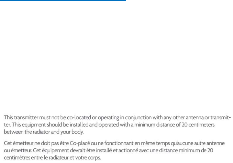
Theantenna(s)usedforthistransmittermustnotbeco‐locatedoroperatinginconjunctionwithany
otherantennaortransmitterandmustbeinstalledtoprovideaseparationdistanceofatleast20cmfrom
allpersons.
FCCRegulations
Thisdevicecomplieswithpart15oftheFCCRules.Operationissubjecttothefollowingtwoconditions:
(1)Thisdevicemaynotcauseharmfulinterference,and(2)thisdevicemustacceptanyinterference
received,includinginterferencethatmaycauseundesiredoperation.
ThisdevicehasbeentestedandfoundtocomplywiththelimitsforaClassBdigitaldevice,pursuantto
Part15oftheFCCRules.
Theselimitsaredesignedtoprovidereasonableprotectionagainstharmfulinterferenceinaresidential
installation.Thisequipmentgenerates,usesandcanradiateradiofrequencyenergyand,ifnotinstalled
andusedinaccordancewiththeinstructions,maycauseharmfulinterferencetoradiocommunications.
Canada Regulations:
This device complies with Industry Canada’s licence-exempt RSSs. Operation is subject to the
following two conditions:
(1) This device may not cause interference; and
(2) This device must accept any interference, including interference that may cause undesired
operation of the device.
Le présentappareilestconforme aux CNR d’Industrie Canada applicables aux appareils radio exempts
de licence. L’exploitationestautorisée aux deux conditions suivantes :
(1) l’appareil ne doit pas produire de brouillage;
(2) l’utilisateur de l’appareildoit accepter tout brouillageradioélectriquesubi, mêmesi le brouillageest
susceptible d’encompromettre le fonctionnement.
Caution:
Alabelwiththefollowingstatementsmustbeattachedtothehostendproduct:ThisdevicecontainsIC:
21098‐ESPWROOM02D.
Themanualprovidesguidancetothehostmanufacturerwillbeincludedinthedocumentationthatwillbe
providedtotheOEM.
Themoduleislimitedtoinstallationinmobileorfixedapplications.
Theseparateapprovalisrequiredforallotheroperatingconfigurations,includingportableconfigurationsand
differentantennaconfigurations.
TheOEMintegratorsareresponsibleforensuringthattheend‐userhasnomanualorinstructionstoremove
orinstallmodule.
ThemoduleislimitedtoOEMinstallationONLY.
Uneétiquetteaveclesinstructionssuivantesdoitêtreattachéeauproduitfinalhôte:
CetappareilcontientIC:21098‐ESPWROOM02D.
Lemanuelfournitdesconseilsaufabricanthôteserainclusdansladocumentationquiserafournieàl'OEM.
Lemoduleestlimitéàl'installationdansdesapplicationsmobilesoufixes.
L'approbationdistincteestrequisepourtouteslesautresconfigurationsdefonctionnement,ycomprisles
configurationsportablesetdifférentesconfigurationsd'antenne.
LesintégrateursOEMsontresponsablesdes'assurerquel'utilisateurn'apasdemanueloud'instructions
pourretirerouinstallerlemodule.
Lemoduleestlimitéàl'installationOEMSEULEMENT.